EP4246018A1 - Lubricating oil deflector, speed reducer comprising such a deflector and turbomachine comprising such a speed reducer - Google Patents
Lubricating oil deflector, speed reducer comprising such a deflector and turbomachine comprising such a speed reducer Download PDFInfo
- Publication number
- EP4246018A1 EP4246018A1 EP23160827.4A EP23160827A EP4246018A1 EP 4246018 A1 EP4246018 A1 EP 4246018A1 EP 23160827 A EP23160827 A EP 23160827A EP 4246018 A1 EP4246018 A1 EP 4246018A1
- Authority
- EP
- European Patent Office
- Prior art keywords
- deflector
- lubricating oil
- speed reducer
- turbomachine
- oil
- Prior art date
- Legal status (The legal status is an assumption and is not a legal conclusion. Google has not performed a legal analysis and makes no representation as to the accuracy of the status listed.)
- Pending
Links
Images


Classifications
-
- F—MECHANICAL ENGINEERING; LIGHTING; HEATING; WEAPONS; BLASTING
- F16—ENGINEERING ELEMENTS AND UNITS; GENERAL MEASURES FOR PRODUCING AND MAINTAINING EFFECTIVE FUNCTIONING OF MACHINES OR INSTALLATIONS; THERMAL INSULATION IN GENERAL
- F16H—GEARING
- F16H57/00—General details of gearing
- F16H57/04—Features relating to lubrication or cooling or heating
- F16H57/042—Guidance of lubricant
- F16H57/0427—Guidance of lubricant on rotary parts, e.g. using baffles for collecting lubricant by centrifugal force
-
- F—MECHANICAL ENGINEERING; LIGHTING; HEATING; WEAPONS; BLASTING
- F16—ENGINEERING ELEMENTS AND UNITS; GENERAL MEASURES FOR PRODUCING AND MAINTAINING EFFECTIVE FUNCTIONING OF MACHINES OR INSTALLATIONS; THERMAL INSULATION IN GENERAL
- F16H—GEARING
- F16H57/00—General details of gearing
- F16H57/04—Features relating to lubrication or cooling or heating
- F16H57/0412—Cooling or heating; Control of temperature
-
- F—MECHANICAL ENGINEERING; LIGHTING; HEATING; WEAPONS; BLASTING
- F01—MACHINES OR ENGINES IN GENERAL; ENGINE PLANTS IN GENERAL; STEAM ENGINES
- F01D—NON-POSITIVE DISPLACEMENT MACHINES OR ENGINES, e.g. STEAM TURBINES
- F01D15/00—Adaptations of machines or engines for special use; Combinations of engines with devices driven thereby
- F01D15/12—Combinations with mechanical gearing
-
- F—MECHANICAL ENGINEERING; LIGHTING; HEATING; WEAPONS; BLASTING
- F01—MACHINES OR ENGINES IN GENERAL; ENGINE PLANTS IN GENERAL; STEAM ENGINES
- F01D—NON-POSITIVE DISPLACEMENT MACHINES OR ENGINES, e.g. STEAM TURBINES
- F01D25/00—Component parts, details, or accessories, not provided for in, or of interest apart from, other groups
- F01D25/18—Lubricating arrangements
-
- F—MECHANICAL ENGINEERING; LIGHTING; HEATING; WEAPONS; BLASTING
- F16—ENGINEERING ELEMENTS AND UNITS; GENERAL MEASURES FOR PRODUCING AND MAINTAINING EFFECTIVE FUNCTIONING OF MACHINES OR INSTALLATIONS; THERMAL INSULATION IN GENERAL
- F16H—GEARING
- F16H1/00—Toothed gearings for conveying rotary motion
- F16H1/28—Toothed gearings for conveying rotary motion with gears having orbital motion
-
- F—MECHANICAL ENGINEERING; LIGHTING; HEATING; WEAPONS; BLASTING
- F16—ENGINEERING ELEMENTS AND UNITS; GENERAL MEASURES FOR PRODUCING AND MAINTAINING EFFECTIVE FUNCTIONING OF MACHINES OR INSTALLATIONS; THERMAL INSULATION IN GENERAL
- F16H—GEARING
- F16H57/00—General details of gearing
- F16H57/04—Features relating to lubrication or cooling or heating
- F16H57/0412—Cooling or heating; Control of temperature
- F16H57/0415—Air cooling or ventilation; Heat exchangers; Thermal insulations
-
- F—MECHANICAL ENGINEERING; LIGHTING; HEATING; WEAPONS; BLASTING
- F16—ENGINEERING ELEMENTS AND UNITS; GENERAL MEASURES FOR PRODUCING AND MAINTAINING EFFECTIVE FUNCTIONING OF MACHINES OR INSTALLATIONS; THERMAL INSULATION IN GENERAL
- F16H—GEARING
- F16H57/00—General details of gearing
- F16H57/04—Features relating to lubrication or cooling or heating
- F16H57/045—Lubricant storage reservoirs, e.g. reservoirs in addition to a gear sump for collecting lubricant in the upper part of a gear case
-
- F—MECHANICAL ENGINEERING; LIGHTING; HEATING; WEAPONS; BLASTING
- F16—ENGINEERING ELEMENTS AND UNITS; GENERAL MEASURES FOR PRODUCING AND MAINTAINING EFFECTIVE FUNCTIONING OF MACHINES OR INSTALLATIONS; THERMAL INSULATION IN GENERAL
- F16H—GEARING
- F16H57/00—General details of gearing
- F16H57/04—Features relating to lubrication or cooling or heating
- F16H57/0456—Lubrication by injection; Injection nozzles or tubes therefor
-
- F—MECHANICAL ENGINEERING; LIGHTING; HEATING; WEAPONS; BLASTING
- F16—ENGINEERING ELEMENTS AND UNITS; GENERAL MEASURES FOR PRODUCING AND MAINTAINING EFFECTIVE FUNCTIONING OF MACHINES OR INSTALLATIONS; THERMAL INSULATION IN GENERAL
- F16H—GEARING
- F16H57/00—General details of gearing
- F16H57/04—Features relating to lubrication or cooling or heating
- F16H57/0467—Elements of gearings to be lubricated, cooled or heated
- F16H57/0479—Gears or bearings on planet carriers
-
- F—MECHANICAL ENGINEERING; LIGHTING; HEATING; WEAPONS; BLASTING
- F16—ENGINEERING ELEMENTS AND UNITS; GENERAL MEASURES FOR PRODUCING AND MAINTAINING EFFECTIVE FUNCTIONING OF MACHINES OR INSTALLATIONS; THERMAL INSULATION IN GENERAL
- F16H—GEARING
- F16H57/00—General details of gearing
- F16H57/04—Features relating to lubrication or cooling or heating
- F16H57/048—Type of gearings to be lubricated, cooled or heated
- F16H57/0482—Gearings with gears having orbital motion
- F16H57/0486—Gearings with gears having orbital motion with fixed gear ratio
-
- F—MECHANICAL ENGINEERING; LIGHTING; HEATING; WEAPONS; BLASTING
- F05—INDEXING SCHEMES RELATING TO ENGINES OR PUMPS IN VARIOUS SUBCLASSES OF CLASSES F01-F04
- F05D—INDEXING SCHEME FOR ASPECTS RELATING TO NON-POSITIVE-DISPLACEMENT MACHINES OR ENGINES, GAS-TURBINES OR JET-PROPULSION PLANTS
- F05D2260/00—Function
- F05D2260/40—Transmission of power
- F05D2260/403—Transmission of power through the shape of the drive components
- F05D2260/4031—Transmission of power through the shape of the drive components as in toothed gearing
- F05D2260/40311—Transmission of power through the shape of the drive components as in toothed gearing of the epicyclical, planetary or differential type
Definitions
- the present presentation concerns a lubricating oil deflector, a speed reducer comprising such a deflector as well as an aircraft turbojet engine with a fan comprising such a speed reducer.
- FIG. 1 represents a cross-sectional view of a speed reducer according to the prior art.
- This figure illustrates an architecture in which the speed reducer 1 comprises a central planetary pinion 2 driven by an input shaft (not shown) movable in rotation around an axis outer ring gear 3 coaxial with the planetary pinion 2.
- the reduction gear 1 further comprises satellite gears 4 which are meshed both with the planetary pinion 2 and with the outer ring gear 3.
- the planet gears 4 are rotatably mounted on pivots 5 of a part called planet carrier 7 of the reducer 1.
- the teeth of the planetary pinion 2, the crown 3 and the satellite gears 4 are lubricated by cold lubricating oil which is conveyed through oil distribution channels (not shown) from a oil tank (not shown).
- turbojets at high bypass ratios requires a particularly large oil flow, to ensure the lubrication and cooling of the pinions and bearings and thus ensure the proper functioning of the reduction gear and the safety of the turbojet.
- the ventilation of the gears is the cause of heating of the cold oil due to the resistive torque phenomenon applied to the gearbox 1 by the air.
- the energy generated by this heating is then dissipated by setting the air in motion, which leads to an increase in the temperature in the gearbox which could harm the safety of the gearbox and therefore of the turbojet.
- the present invention relates to a lubricating oil deflector for a turbomachine speed reducer, the deflector comprising a body having a first end intended to be arranged in view of a sun gear of the reducer, the first end being configured to receive oil from the sun gear and a second opposite end configured to evacuate the oil from the body, the body comprising two side faces each intended to be arranged in view of a satellite pinion of the reducer and which each connect the first and second ends together, the body comprising at least one internal oil guiding channel which opens at the first end and at the second end and is configured to drain the oil by gravity through the second end.
- the configuration of the deflector thus allows, when the latter is arranged in such a way that the first end is at a level located above the level of the second end, under the effect of earth's gravity, to collect lubricating oil present at the first end and transfer it inside the body, to convey it away from the first end and evacuate it, at the second distant end, in a direction opposite to the first end.
- the deflector When the deflector is placed in a speed reducer in such a way that the first end is arranged opposite the sun pinion of the reducer, the oil present at the first end is recovered at least in part by the latter and transferred to the second end where it is evacuated, which makes it possible to limit the re-circulation of oil around the solar pinion and therefore to reduce ventilation losses.
- the present invention relates to a speed reducer of a turbomachine, characterized in that it comprises at least one lubricating oil deflector as briefly explained above.
- This speed reducer has the same characteristics and advantages as the aforementioned deflector.
- the present invention relates to a turbomachine comprising a turbomachine speed reducer as briefly explained above.
- the satellite gears 14 are engaged, that is to say meshed, with the sun pinion 12.
- the satellite pinions 14 are also engaged, that is to say meshed, with an external ring gear (not shown but similar to the ring gear 3 of the figure 1 ) coaxial with the sun pinion 2. These satellite pinions 14 are rotatably mounted on pivots of a planet carrier part not shown of the reducer 10.
- the figure 1 illustrates a possible configuration for the speed reducer 10, except the number of planet gears which is likely to vary.
- the planet carrier In the speed reducer 10 the planet carrier is fixed and the external ring gear is free to rotate (planetary gearbox).
- the planetary gearbox can be configured in one stage or two stages.
- the planetary architecture has, for example, a reduction ratio of approximately 2 to 6.
- the teeth of the sun gear 12, the outer ring gear and the satellite gears 14 are lubricated by cold lubricating oil which is conveyed through oil distribution channels (not shown) from a oil tank (not shown).
- the reduction gear 10 comprises a lubricating oil deflector 20 (fixed to the planet carrier) which extends vertically along the Z axis in a vertical inter-gear space located between the central sun gear 12 and the two adjacent planet gears 14a , 14b located below the sun pinion 12.
- the two adjacent satellite gears 14a, 14b are rotatably mounted on pivots with respective axes Pa, Pb of the planet carrier part not shown and these axes form with the axis from the central pinion 12 a triangle (illustrated in dotted lines in Figure 3) whose tip is oriented upwards and whose base connecting the axes Pa and Pb is horizontal.
- the gravity deflector 20 is thus positioned in the lower part of the reducer 10 so as to promote gravity flow.
- the gravity deflector 20 generally comprises a body 22 having a first and a second opposite ends 24 and 26.
- the first end 24 of the gravity deflector is oriented opposite the sun pinion 12 and is located at a vertical position (along the Z axis) greater than that of the second opposite end 26 of the deflector which is located at a distance from the sun pinion (along the axis Z), between the two corresponding adjacent satellite gears 14a, 14b which frame it.
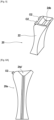
- THE figures 4 And 5 represent the deflector 20 without the reducer which can integrate it.
- the first end 24, oriented upwards, is configured to receive lubricating oil and here has the shape of a bowl 24a for receiving lubricating oil which collects in particular the oil present in the zone located between the sun pinion 12 and the first end 24.
- the body 22 comprises at least one internal channel (or conduit) 28 for guiding or conveying the oil collected by the bowl 24a and which extends in a longitudinal direction of extension (here the direction is coincident with the vertical), from the first end 24, in particular of the bowl 24a, to the second opposite end 26.
- the oil collected by the bowl 24a flows vertically in the internal channel 28 under the action of gravity and reaches there second opposite end 26 through which the oil is discharged/ejected out of the body by gravity.
- a single internal channel 28 is present in the body.
- several channels internal to the body can be envisaged to increase the flow of oil to be evacuated, for example by being arranged parallel to one another in the background on the figure 4 (e.g. dual channel).
- the internal channel 28 can adopt different shapes (in particular its passage section) and dimensions depending on the applications envisaged.
- the internal channel can thus have a rectangular passage section as illustrated in the Figure 5 , an oblong, circular passage section...
- FIG 5 shows in perspective a possible example of the shape of a bowl 24a for receiving lubricating oil where the bowl has curved (concave) walls oriented downwards, substantially forming a V, which open partly through an elongated slot 24b (for example example of substantially rectangular shape) forming an inlet opening of the internal channel 28.
- the body 22 has a generally elongated shape which extends from the first end 24 to the second end 26 and which is curved in a part disposed between the first end and the second end and at a distance therefrom.
- the curved part is here the central part 22a of the body according to the cross-sectional view of the figures 3 and 4 .
- the two opposite ends 24 and 26 each have a generally flared shape moving away from the central part 22a of the body.
- the general diabolo shape of the body is thus adapted to the general shape of the vertical inter-gear space defined above and illustrated on the Figure 3 .
- the second end 26 of the body takes the form of a substantially flat face 26a which is arranged horizontally when the deflector 20 is in the position of the Figure 3 .
- An outlet opening 26b of the internal channel 28a opens at the level of the flat end face 26a to evacuate the oil which flows by gravity into the channel.
- the body has a thickness (dimension perpendicular to the plane of the Figure 4 ) which is here constant and a general rectangular shape following a view taken in the direction of the lateral arrow indicated in this figure.
- the internal channel 28 extends here along a large part of the thickness of the body.
- the lubricating oil receiving bowl 24a is positioned at the first end of the body offset in a transverse direction relative to the longitudinal direction of extension of the internal channel 28. Taking into account the vertical orientation of the longitudinal direction extension, the bowl 24a is thus offset laterally, that is to say horizontally towards one of the two opposite lateral sides of the first end 24.
- the internal channel 28 is also also offset laterally towards the corresponding side from the body. This laterally offset arrangement of the bowl 24a can make it possible, for example, to promote the recovery of oil coming from a zone which is located between the sun pinion 12 and the satellite pinion 14b and towards which the bowl is laterally offset.
- the first end 24 of the body is provided, in a manner offset transversely relative to the longitudinal direction of extension of the channel, with lubricating oil outlet orifices 02 (solar gear lubrication nozzles -satellites).
- lubricating oil outlet orifices 02 solar gear lubrication nozzles -satellites.
- two outlet orifices 02 are shown, aligned according to the thickness of the body 22 but a different number can alternatively be considered (a transverse conduit not shown makes it possible to convey oil coming from the bowl 24a to the ejection points 02).
- These orifices facilitate external lubrication of the planet gears and can also contribute to the lubrication of the bearings (outlets for lubrication of the teeth).
- the gravity deflector 20 has mainly two functions: it guides the lubricating oil between the deflector and each of the satellite gears 14a, 14b and it guides the oil through internal pipework by gravity from the first end 24 to the second end 26.
- the gravity deflector 20 aims to capture/accumulate, in the bowl 24a forming a retention pocket, part of the oil present in the circumferential groove (not shown) of the sun pinion 12.
- the collected oil accumulates in this bowl where it is slowed down before flowing through the opening 24b through the internal channel 28 under the effect of gravity, thus accelerating the flow of oil.
- the internal channel 28 opens at a distance from the sun pinion and the oil is thus evacuated by gravity, leaving through the opening 26b, towards the external ring surrounding the arrangement of the figure 2 , like crown 3 of the figure 1 .
- the gravity deflector 20 plays the role of a gravity effect accumulator which ensures the internal transfer of part of the oil present in the circumferential groove of the sun pinion 12 to evacuate it out of this zone and towards the external crown.
- gravity deflector 20 can be manufactured in different ways, for example by cutting into the mass of a block, by additive manufacturing, by foundry or other.
- the figures 6A And 6B illustrate two possible configurations of deflectors 20a and 20b according to which, respectively, the bowl 24a' has, in section, a generally conical shape and the bowl 24a" has, in section, a generally rectangular shape.
- the other characteristics of the deflector can be identical to the deflector 20 described above.
- FIG. 7 illustrates another embodiment of a speed reducer 10' in which one or more gravity deflectors 20', 20", 20'" can be installed in an inter-pinion space. Only two adjacent satellite gears 14' of the lower part of the reducer and the sun gear 12' are shown in solid lines (two other satellite gears adjacent to the first two are partially shown schematically in dotted lines) but the configuration is generally the same as that of there figure 2 .
- a gravity deflector 20", 20'" can be positioned between the sun pinion 12' and two adjacent satellite pinions 14' in such a way that the first end of the gravity deflector is oriented opposite the solar pinion 12' and is located at a vertical position greater than that of the second opposite end of the deflector concerned.
- the second opposite end of the deflector concerned is located at a distance from the sun pinion 12', between the two corresponding satellite gears 14'.
- a gravity deflector 20", 20'" thus extends obliquely, relative to the vertical Z, between the sun pinion 12' and the two adjacent satellite pinions 14' in solid lines.
- the angle of inclination between the gravity deflector concerned and the vertical passing through the gravity deflector 20' depends in particular on the number of satellite gears 14'. The higher this number, the lower the angle of inclination.
- the configuration of the 20", 20'" side gravity baffles is generally different from that of the 20' gravity baffle although the general external shape may be identical.
- the slope of the internal channel for guiding the oil flow 28" and 28'" for the deflectors 20" and 20'" (evacuation slope) can be modified in relation to the configuration of the internal channel 28 of there Figure 4 (this channel 28 is aligned with the general longitudinal direction of the deflector 20), in order to promote the flow of oil towards the bottom of the reducer.
- each internal guide channel 28" and 28'" is inclined downwards relative to the general longitudinal direction of the deflector considered, schematized by the dotted line D1, D2 on the Figure 7 .
- the receiving bowl (not shown here) can also be modified compared to that of the Figure 4 , for example, as on the figures 6A And 6B or in another way.
- the reducer 10' can also include the deflector 20' identical to the deflector 20 of the figures 2 to 5 .
- the reducer 10' may comprise the deflector 20' identical to the deflector 20 of the figures 2 to 5 and one of the 20", 20'" deflectors or all of the three 20', 20" and 20'" deflectors.
- the reducer 10' can include only one or the other of the deflectors 20", 20"', without the deflector 20'.
- FIG 8 illustrates a possible example of a turbomachine (following an axial half-section relative to the longitudinal axis a blower S, a low pressure compressor 30a, a high pressure compressor 30b, an annular combustion chamber 30c, a high pressure turbine 30d, a low pressure turbine 30e and an exhaust nozzle 30f.
- the high pressure compressor 30b and the high pressure turbine 30d are connected by a high pressure shaft 32 and with it form a high pressure body (HP).
- the low pressure compressor 30a and the low pressure turbine 30e are connected by a low pressure shaft 33 and with it form a low pressure body (LP).
- the fan S is driven by a fan shaft 34 which is driven by the BP shaft 33 by means of a speed reducer 36.
- This reducer is here of the planetary type and is positioned in the front part of the turbomachine.
- a fixed structure comprising schematically, here, an upstream part 35a and a downstream part 35b which makes up the motor casing or stator 35 is arranged so as to form an enclosure E surrounding the reduction gear 36.
- This enclosure E is here closed upstream by seals at the level of a landing allowing crossing of the fan shaft 34 and downstream by joints at the crossing of the BP shaft 33.
- FIG. 9 illustrates a possible example of configuration (following an axial half-section) for the reducer 36 of the figure 8 .
- the reducer 36 is connected to the BP shaft 33, for example via splines 37a.
- the BP shaft 33 drives a sun pinion 37.
- the sun pinion 37 whose axis of rotation coincides with that of the turbomachine of the axis of rotation
- the set of satellite gears 38 is held, at the output, by a frame called planet carrier 40.
- Each satellite 38 rotates around its own axis Y, and meshes with the external ring gear 39.
- the planet carrier 40 is fixed to the motor casing or stator 35 of the figure 8 .
- Each satellite 38 drives the crown 39 which is attached to the fan shaft 34 ( fig. 8 ) via a crown holder 42.
- Each satellite 38 is mounted to rotate freely using a bearing 41, for example of the rolling or hydrostatic bearing type.
- Each bearing 41 is mounted on one of the axes 40b of the planet carrier 40 and all the axes are positioned relative to each other using one or more structural frames 40a of the planet carrier 40.
- the teeth of a gearbox can, for example, be separated into several helices.
- the operation of a reducer with several propellers with a crown separated into two half-crowns will be described below.
- a front half-crown 39a is made up of a rim 39aa and a half-fixing flange 39ab. On the 39aa rim is the front propeller of the gearbox teeth. This front propeller meshes with that of satellite 38 which meshes with that of solar 37.
- a rear half-crown 39b consisting of a rim 39ba and a half-fixing flange 39bb.
- On the 39ba rim is the rear propeller of the reduction gear teeth. This rear propeller meshes with that of satellite 38 which meshes with that of solar 37.
- the half-fixing flange 39ab of the front crown 39a and the half-fixing flange 39bb of the rear crown 39b form the fixing flange 39c of the crown.
- the crown 39 is fixed to a crown holder by assembling the fixing flange 39c of the crown and the fixing flange 42a of the crown holder using a bolted assembly for example.
- the arrows of the Figure 9 describe the routing of the oil in the gearbox 36.
- the oil arrives in the gearbox 36 from the stator part 35 ( fig. 8 ) in the distributor 43 by different means which will not be specified in this view because they are specific to one or more types of architecture.
- the distributor is separated into two parts in general, each repeated with the same number of satellites.
- the injectors 43a have the function of lubricating the teeth and the arms 43b have the function of lubricating the bearings.
- the oil is brought towards the injector 43a to exit through the end 43c in order to lubricate the teeth.
- the oil is also brought to the arm 43b and circulates via the supply port 43d of the bearing.
- the oil then circulates through the axis in one or more buffer zones 40c to then exit through the orifices 40d in order to lubricate the satellite bearings.
Abstract
L'invention concerne un déflecteur (20) d'huile de lubrification pour un réducteur de vitesse d'une turbomachine, le déflecteur comprenant un corps (22) ayant une première extrémité (24) destinée à être disposée en regard d'un pignon solaire du réducteur, la première extrémité étant configurée pour recevoir de l'huile du pignon solaire et une deuxième extrémité opposée (26) configurée pour évacuer l'huile hors du corps (22), le corps (22) comportant deux faces latérales destinées chacune à être disposées en regard d'un pignon satellite du réducteur et qui relient chacune la première et la deuxième extrémité (24, 26) entre elles, le corps (22) comportant au moins un canal interne de guidage de l'huile qui débouche à la première extrémité (24) et à la deuxième extrémité (26) et est configuré pour évacuer l'huile par gravité à travers la deuxième extrémité (26).

Description
Le présent exposé concerne un déflecteur d'huile de lubrification, un réducteur de vitesse comportant un tel déflecteur ainsi qu'un turboréacteur d'aéronef à soufflante comportant un tel un réducteur de vitesse.The present presentation concerns a lubricating oil deflector, a speed reducer comprising such a deflector as well as an aircraft turbojet engine with a fan comprising such a speed reducer.
Les turbomachines d'aéronef à soufflante actuels à haut taux de dilution comportent un système de transmission mécanique, appelé réducteur, qui a pour fonction d'entraîner en rotation l'arbre de la soufflante (appelée en terminologie anglosaxonne « fan ») à partir de la rotation d'une turbine de puissance de la ligne basse pression du turboréacteur. Le réducteur permet ainsi de transformer la vitesse de rotation de l'arbre de la turbine de puissance en une vitesse de rotation réduite pour l'arbre entraînant la soufflante. De manière générale, le réducteur doit transmettre la puissance motrice vers la soufflante tout en assurant le rapport de vitesse demandé et ce, dans des contraintes d'encombrement et de masse très sévères. Plusieurs architectures et technologies sont possibles pour le réducteur et l'architecture retenue dépend en premier lieu du rapport de réduction des vitesses.Current aircraft turbomachines with high bypass ratio fans include a mechanical transmission system, called a reduction gear, which has the function of rotating the fan shaft (called "fan" in English terminology) from the rotation of a power turbine of the low pressure line of the turbojet. The reduction gear thus makes it possible to transform the rotational speed of the power turbine shaft into a reduced rotational speed for the shaft driving the fan. Generally speaking, the gearbox must transmit the motive power to the fan while ensuring the requested speed ratio, within very severe space and weight constraints. Several architectures and technologies are possible for the gearbox and the architecture chosen depends primarily on the speed reduction ratio.
La
Comme indiqué ci-dessus, deux configurations de réducteur sont envisageables :
- les réducteurs planétaires dans lesquels le porte-satellites 7 est fixe et la
couronne 3 est libre en rotation ; - les réducteurs épicycloidaux dans lesquels la
couronne 3 est fixe et le porte-satellites 7 est libre en rotation.
- planetary gearboxes in which the planet carrier 7 is fixed and the
crown 3 is free to rotate; - the epicyclic reducers in which the
crown 3 is fixed and the planet carrier 7 is free to rotate.
De manière connue, les dentures du pignon planétaire 2, de la couronne 3 et des pignons satellites 4 sont lubrifiées par de l'huile de lubrification froide qui est acheminée par des canaux de distribution d'huile (non représentés) à partir d'un réservoir d'huile (non représenté).In known manner, the teeth of the
Le fonctionnement des turboréacteurs à taux de dilution élevés nécessite un débit d'huile particulièrement important, pour assurer la lubrification et le refroidissement des pignons et des paliers et ainsi assurer le bon fonctionnement du réducteur et la sécurité du turboréacteur.The operation of turbojets at high bypass ratios requires a particularly large oil flow, to ensure the lubrication and cooling of the pinions and bearings and thus ensure the proper functioning of the reduction gear and the safety of the turbojet.
Cependant, la ventilation des pignons est à l'origine d'un échauffement de l'huile froide dû au phénomène de couple résistif appliqué au réducteur 1 par l'air. L'énergie générée par cet échauffement est alors dissipée par mise en mouvement de l'air, ce qui conduit à une augmentation de la température dans le réducteur pouvant nuire à la sûreté du réducteur et donc du turboréacteur.However, the ventilation of the gears is the cause of heating of the cold oil due to the resistive torque phenomenon applied to the
Il a été constaté qu'une grande recirculation d'huile se produit autour de la gorge (non représentée) du pignon planétaire 2 et provoque des pertes par ventilation de l'huile dans le réducteur, ce qui dégrade notamment le rendement du réducteur.It was noted that a large recirculation of oil occurs around the groove (not shown) of the
Il existe donc un besoin de réduire les pertes par ventilation et d'améliorer le rendement du réducteur.There is therefore a need to reduce ventilation losses and improve the efficiency of the reducer.
A cet effet, la présente invention concerne un déflecteur d'huile de lubrification pour un réducteur de vitesse de turbomachine, le déflecteur comprenant un corps ayant une première extrémité destinée à être disposée en regard d'un pignon solaire du réducteur, la première extrémité étant configurée pour recevoir de l'huile du pignon solaire et une deuxième extrémité opposée configurée pour évacuer l'huile hors du corps, le corps comportant deux faces latérales destinées chacune à être disposées en regard d'un pignon satellite du réducteur et qui relient chacune la première et la deuxième extrémité entre elles, le corps comportant au moins un canal interne de guidage de l'huile qui débouche à la première extrémité et à la deuxième extrémité et est configuré pour évacuer l'huile par gravité à travers la deuxième extrémité.To this end, the present invention relates to a lubricating oil deflector for a turbomachine speed reducer, the deflector comprising a body having a first end intended to be arranged in view of a sun gear of the reducer, the first end being configured to receive oil from the sun gear and a second opposite end configured to evacuate the oil from the body, the body comprising two side faces each intended to be arranged in view of a satellite pinion of the reducer and which each connect the first and second ends together, the body comprising at least one internal oil guiding channel which opens at the first end and at the second end and is configured to drain the oil by gravity through the second end.
La configuration du déflecteur permet ainsi, lorsque ce dernier est agencé de telle manière que la première extrémité soit à une cote située au-dessus de la cote de la deuxième extrémité, sous leffet de la gravité terrestre, de recueillir de l'huile de lubrification présente au niveau de la première extrémité et de la transférer à l'intérieur du corps, pour l'acheminer à distance de la première extrémité et l'évacuer, au niveau de la deuxième extrémité distante, dans une direction opposée à la première extrémité.The configuration of the deflector thus allows, when the latter is arranged in such a way that the first end is at a level located above the level of the second end, under the effect of earth's gravity, to collect lubricating oil present at the first end and transfer it inside the body, to convey it away from the first end and evacuate it, at the second distant end, in a direction opposite to the first end.
Lorsque le déflecteur est placé dans un réducteur de vitesse de telle manière que la première extrémité est disposée en vis-à-vis du pignon solaire du réducteur, l'huile présente au niveau de la première extrémité est récupérée au moins en partie par cette dernière et transférée jusqu'à la deuxième extrémité où elle est évacuée, ce qui permet de limiter la re-circulation d'huile autour du pignon solaire et donc de réduire les pertes par ventilation.When the deflector is placed in a speed reducer in such a way that the first end is arranged opposite the sun pinion of the reducer, the oil present at the first end is recovered at least in part by the latter and transferred to the second end where it is evacuated, which makes it possible to limit the re-circulation of oil around the solar pinion and therefore to reduce ventilation losses.
Selon d'autres caractéristiques possibles :
- la première extrémité comporte une cuvette de réception d'huile de lubrification destinée à recevoir de l'huile ;
- ledit au moins un canal interne de guidage s'étendant suivant une direction longitudinale d'extension, la cuvette de réception d'huile de lubrification est positionnée à la première extrémité du corps de manière décalée suivant une direction transversale relativement à la direction longitudinale d'extension ;
- ledit au moins un canal interne de guidage s'étendant suivant une direction longitudinale d'extension, la première extrémité du corps est pourvue, de manière décalée suivant une direction transversale relativement à la direction longitudinale d'extension, d'orifices de sortie d'huile de lubrification;
- le corps a une forme générale allongée qui s'étend de la première extrémité à la deuxième extrémité ;
- la forme générale allongée du corps est cintrée dans une partie qui est disposée entre la première extrémité et la deuxième extrémité et à distance de celles-ci
- le corps comporte en outre un conduit interne agencé transversalement par rapport à la forme générale allongée du corps.
- the first end has a lubricating oil receiving bowl for receiving oil;
- said at least one internal guide channel extending in a longitudinal direction of extension, the lubricating oil receiving bowl is positioned at the first end of the body offset in a transverse direction relative to the longitudinal direction of extension ;
- said at least one internal guide channel extending in a longitudinal direction of extension, the first end of the body is provided, offset in a transverse direction relative to the direction longitudinal extension, lubricating oil outlet ports;
- the body has a generally elongated shape which extends from the first end to the second end;
- the generally elongated shape of the body is bent in a portion which is disposed between and at a distance from the first end and the second end
- the body further comprises an internal conduit arranged transversely with respect to the general elongated shape of the body.
Selon un autre objet, la présente invention concerne un réducteur de vitesse d'une turbomachine, caractérisé en ce qu'il comprend au moins un déflecteur d'huile de lubrification tel que brièvement exposé ci-dessus.According to another object, the present invention relates to a speed reducer of a turbomachine, characterized in that it comprises at least one lubricating oil deflector as briefly explained above.
Ce réducteur de vitesse comporte les mêmes caractéristiques et avantages que le déflecteur précité.This speed reducer has the same characteristics and advantages as the aforementioned deflector.
Selon d'autres caractéristiques possibles :
- le réducteur comprend une architecture du type comprenant un pignon solaire et des pignons satellites qui sont disposés autour du pignon solaire et qui sont en prise, d'une part, avec le pignon solaire et, d'autre part, avec une couronne qui s'étend autour des pignons satellites ;
- les pignons satellites sont agencés suivant une disposition verticale autour du pignon solaire, un ou plusieurs déflecteurs d'huile de lubrification tels que brièvement exposés ci-dessus s'étendant chacun entre le pignon solaire et deux pignons satellites adjacents de telle manière que la première extrémité du ou des déflecteurs soit orientée en vis-à-vis du pignon solaire et soit située à une position verticale supérieure à celle de la deuxième extrémité opposée du déflecteur concerné qui est située à distance du pignon solaire, entre les deux pignons satellites adjacents correspondants ;
- le réducteur comporte un déflecteur d'huile de lubrification qui s'étend verticalement entre le pignon solaire et deux pignons satellites adjacents;
- le réducteur comporte un au moins un déflecteur d'huile de lubrification qui s'étend de manière oblique entre le pignon solaire et deux pignons satellites adjacents.
- the reducer comprises an architecture of the type comprising a sun pinion and satellite gears which are arranged around the sun pinion and which engage, on the one hand, with the sun pinion and, on the other hand, with a crown which extends around the satellite gears;
- the planet gears are arranged in a vertical arrangement around the sun gear, one or more lubricating oil baffles as briefly discussed above each extending between the sun gear and two adjacent planet gears such that the first end of the deflector(s) is oriented opposite the sun pinion and is located at a vertical position greater than that of the second opposite end of the deflector concerned which is located at a distance from the sun pinion, between the two corresponding adjacent satellite pinions;
- the gearbox has a lubricating oil baffle which extends vertically between the sun gear and two adjacent planet gears;
- the gearbox comprises at least one lubricating oil deflector which extends obliquely between the sun gear and two adjacent satellite gears.
Selon encore un autre objet, la présente invention concerne une turbomachine comprenant un réducteur de vitesse de turbomachine tel que brièvement exposé ci-dessus.According to yet another object, the present invention relates to a turbomachine comprising a turbomachine speed reducer as briefly explained above.
L'objet du présent exposé et ses avantages seront mieux compris à la lecture de la description détaillée faite ci-après de différents exemples de réalisation donnés à titre d'exemples non limitatifs. Cette description fait référence aux pages de figures annexées, sur lesquelles :
- [
Fig. 1 ] Lafigure 1 représente une vue schématique en coupe transversale d'un réducteur de vitesse selon l'art antérieur; - [
Fig. 2 ] Lafigure 2 représente une vue schématique simplifiée et partielle d'un réducteur de vitesse d'un turboréacteur d'aéronef à soufflante selon un exemple de réalisation de l'invention; - [
Fig. 3 ] Lafigure 3 représente une vue schématique agrandie du réducteur de vitesse de lafigure 2 montrant un déflecteur selon un exemple de réalisation de l'invention; - [
Fig. 4 ] Lafigure 4 représente une vue schématique en section transversale du déflecteur de lafigure 3 ; - [
Fig. 5 ] Lafigure 5 représente une vue schématique en perspective du déflecteur de lafigure 4 ; - [
Fig. 6A ] Lafigure 6A représente une variante possible de la configuration d'un déflecteur gravitaire selon l'invention ; - [
Fig. 6B ] Lafigure 6B représente une autre variante possible de la configuration d'un déflecteur gravitaire selon l'invention ; - [
Fig. 7 ] Lafigure 7 représente une vue schématique simplifiée, analogue à celle de lafigure 2 et agrandie, montrant l'implantation possible d'un déflecteur selon un exemple de réalisation de l'invention ; - [
Fig. 8 ] Lafigure 8 représente suivant une vue en demi-coupe axiale un exemple de turbomachine intégrant l'invention ; - [
Fig. 9 ] Lafigure 9 représente une architecture possible d'un réducteur de vitesse de la turbomachine de lafigure 8 et susceptible d'incorporer l'invention.
- [
Fig. 1 ] Therefigure 1 represents a schematic cross-sectional view of a speed reducer according to the prior art; - [
Fig. 2 ] Therefigure 2 represents a simplified and partial schematic view of a speed reducer of a fan aircraft turbojet according to an exemplary embodiment of the invention; - [
Fig. 3 ] ThereFigure 3 represents an enlarged schematic view of the speed reducer of thefigure 2 showing a deflector according to an exemplary embodiment of the invention; - [
Fig. 4 ] ThereFigure 4 represents a schematic cross-sectional view of the deflector of theFigure 3 ; - [
Fig. 5 ] ThereFigure 5 represents a schematic perspective view of the deflector of theFigure 4 ; - [
Fig. 6A ] ThereFigure 6A represents a possible variant of the configuration of a gravity deflector according to the invention; - [
Fig. 6B ] ThereFigure 6B represents another possible variant of the configuration of a gravity deflector according to the invention; - [
Fig. 7 ] ThereFigure 7 represents a simplified schematic view, similar to that of thefigure 2 and enlarged, showing the possible installation of a deflector according to an exemplary embodiment of the invention; - [
Fig. 8 ] Therefigure 8 represents in an axial half-section view an example of a turbomachine incorporating the invention; - [
Fig. 9 ] ThereFigure 9 represents a possible architecture of a speed reducer of the turbomachine of thefigure 8 and capable of incorporating the invention.
Comme représenté à la
Les pignons satellites 14 sont par ailleurs également en prise, c'est-à-dire engrenés, avec une couronne externe (non représentée mais analogue à la couronne 3 de la
Dans le réducteur de vitesse 10 le porte-satellites est fixe et la couronne externe est libre en rotation (réducteur planétaire).In the
Selon le rapport de réduction envisagé, le réducteur planétaire peut être configuré suivant un étage ou deux étages.Depending on the reduction ratio envisaged, the planetary gearbox can be configured in one stage or two stages.
Dans l'exemple de réalisation décrit, bien que cela ne soit nullement limitatif, l'architecture planétaire a, par exemple, un rapport de réduction d'environ 2 à 6.In the embodiment described, although this is in no way limiting, the planetary architecture has, for example, a reduction ratio of approximately 2 to 6.
De manière connue, les dentures du pignon solaire 12, de la couronne externe et des pignons satellites 14 sont lubrifiées par de l'huile de lubrification froide qui est acheminée par des canaux de distribution d'huile (non représentés) à partir d'un réservoir d'huile (non représenté).In known manner, the teeth of the
Dans l'exemple de réalisation illustré sur la
Le déflecteur gravitaire 20 comprend de manière générale un corps 22 ayant une première et une deuxième extrémités opposées 24 et 26. Suivant l'implantation du déflecteur gravitaire 20 dans l'espace vertical inter-pignons défini plus haut, la première extrémité 24 du déflecteur gravitaire est orientée en vis-à-vis du pignon solaire 12 et est située à une position verticale (suivant l'axe Z) supérieure à celle de la deuxième extrémité opposée 26 du déflecteur qui est située à distance du pignon solaire (suivant l'axe Z), entre les deux pignons satellites adjacents correspondants 14a, 14b qui l'encadrent.The
Les
La première extrémité 24, orientée vers le haut, est configurée pour recevoir de l'huile de lubrification et comporte ici la forme d'une cuvette 24a de réception d'huile de lubrification qui recueille notamment l'huile présente dans la zone située entre le pignon solaire 12 et la première extrémité 24.The
Le corps 22 comprend au moins un canal (ou conduit) interne 28 de guidage ou d'acheminement de l'huile recueillie par la cuvette 24a et qui s'étend, suivant une direction longitudinale d'extension (ici la direction est confondue avec la verticale), depuis la première extrémité 24, notamment de la cuvette 24a, jusqu'à la deuxième extrémité opposée 26. L'huile recueillie par la cuvette 24a s'écoule verticalement dans le canal interne 28 sous l'action de la gravité et atteint la deuxième extrémité opposée 26 par laquelle l'huile est évacuée/éjectée hors du corps par gravité.The
Dans le présent exemple de réalisation, un seul canal interne 28 est présent dans le corps. Toutefois, selon d'autres exemples de réalisation non représentés, plusieurs canaux internes au corps peuvent être envisagés pour augmenter le débit d'huile à évacuer, en étant par exemple disposés parallèlement l'un à l'autre en arrière plan sur la
La
Comme représenté sur les
Suivant cette configuration cintrée, les deux extrémités opposées 24 et 26 ont chacune une forme générale évasée en éloignement de la partie centrale 22a du corps. La forme générale en diabolo du corps est ainsi adaptée à la forme générale de l'espace vertical inter-pignons défini plus haut et illustré sur la
La deuxième extrémité 26 du corps prend la forme d'une face sensiblement plane 26a qui est disposée horizontalement lorsque le déflecteur 20 est dans la position de la
Dans l'exemple de réalisation illustré sur la
Comme représenté sur les
Par ailleurs, dans la configuration illustrée, la première extrémité 24 du corps est pourvue, de manière décalée transversalement relativement à la direction longitudinale d'extension du canal, d'orifices de sortie d'huile de lubrification 02 (gicleurs de lubrification des engrènements solaires-satellites). Sur la
Le déflecteur gravitaire 20 a principalement deux fonctions : il guide l'huile de lubrification entre le déflecteur et chacun des pignons satellites 14a, 14b et il guide l'huile par canalisation interne par effet gravitaire de la première extrémité 24 à la deuxième extrémité 26.The
Plus particulièrement, le déflecteur gravitaire 20 vise à capter/accumuler, dans la cuvette 24a formant une poche de rétention, une partie de l'huile présente dans la gorge circonférentielle (non représentée) du pignon solaire 12. L'huile recueillie s'accumule dans cette cuvette où elle est freinée avant de s'écouler par l'ouverture 24b à travers le canal interne 28 sous l'effet de la gravité, accélérant ainsi l'écoulement d'huile. Le canal interne 28 débouche à distance du pignon solaire et l'huile est ainsi évacuée par gravité, en sortant par l'ouverture 26b, en direction de la couronne externe entourant l'agencement de la
Autrement dit, le déflecteur gravitaire 20 joue le rôle d'un accumulateur à effet gravitaire qui assure le transfert interne d'une partie de l'huile présente dans la gorge circonférentielle du pignon solaire 12 pour l'évacuer hors de cette zone et vers la couronne externe.In other words, the
Ceci a pour effet de diminuer la quantité d'huile recirculée autour du pignon solaire 12 et de diminuer les pertes par ventilation de l'huile, améliorant ainsi le rendement du réducteur.This has the effect of reducing the quantity of oil recirculated around the
On notera que le déflecteur gravitaire 20 peut être fabriqué de différents manières, par exemple par taille dans la masse d'un bloc, par fabrication additive, par fonderie ou autre.It will be noted that the
D'autres configurations de déflecteur gravitaire sont bien entendu envisageables au sens de la présente invention afin d'assurer les fonctions mentionnées ci-dessus. La présence des orificesO2 (gicleurs de lubrification) n'est pas indispensable, de même que la position décalée de la cuvette 24a et du canal interne et la forme du corps peut varier dans les limites acceptables pour pouvoir être positionné dans l'espace inter-pignons. Sa dimension longitudinale peut notamment varier pour s'étendre jusqu'à une position plus proche de la couronne que ce qui est représenté sur la
A titre d'exemples, les
La
Ainsi, de manière générale, un déflecteur gravitaire 20", 20'" peut être positionné entre le pignon solaire 12' et deux pignons satellites adjacents 14' de telle manière que la première extrémité du déflecteur gravitaire soit orientée en vis-à-vis du pignon solaire 12' et soit située à une position verticale supérieure à celle de la deuxième extrémité opposée du déflecteur concerné. La deuxième extrémité opposée du déflecteur concerné est située à distance du pignon solaire 12', entre les deux pignons satellites correspondants 14'. Dans cet exemple de réalisation, un déflecteur gravitaire 20", 20'" s'étend ainsi de manière oblique, par rapport à la verticale Z, entre le pignon solaire 12' et les deux pignons satellites adjacents 14' en traits pleins. L'angle d'inclinaison entre le déflecteur gravitaire concerné et la verticale passant par le déflecteur gravitaire 20' dépend notamment du nombre des pignons satellites 14'. Plus ce nombre est élevé plus l'angle d'inclinaison est faible. La configuration des déflecteurs gravitaires latéraux 20", 20'" est généralement différente de celle du déflecteur gravitaire 20' bien que la forme générale externe puisse être identique. En particulier la pente du canal interne de guidage de l'écoulement d'huile 28" et 28'" pour les déflecteurs 20" et 20'" (pente d'évacuation) peut être modifiée par rapport à la configuration du canal interne 28 de la
A titre d'exemple, le réducteur 10' peut également comprendre le déflecteur 20' identique au déflecteur 20 des
Selon une variante non représentée, le réducteur 10' peut comprendre le déflecteur 20' identique au déflecteur 20 des
La
La soufflante S est entraînée par un arbre de soufflante 34 qui est entrainé par l'arbre BP 33 au moyen d'un réducteur de vitesse 36. Ce réducteur est ici de type planétaire et est positionné dans la partie avant de la turbomachine. Une structure fixe comportant schématiquement, ici, une partie amont 35a et une partie aval 35b qui compose le carter moteur ou stator 35 est agencée de manière à former une enceinte E entourant le réducteur 36. Cette enceinte E est ici fermée en amont par des joints au niveau d'un palier permettant la traversée de l'arbre de soufflante 34 et en aval par des joints au niveau de la traversée de l'arbre BP 33.The fan S is driven by a
D'autres configurations de turbomachines sont bien entendu envisageables pour mettre en oeuvre l'invention.Other configurations of turbomachines are of course possible to implement the invention.
La
L'ensemble des pignons satellites 38 est maintenu, en sortie, par un châssis appelé porte-satellites 40. Chaque satellite 38 tourne autour de son propre axe Y, et engrène avec la couronne externe 39.The set of satellite gears 38 is held, at the output, by a frame called
Dans cette configuration planétaire, le porte-satellites 40 est fixé au carter moteur ou stator 35 de la
Chaque satellite 38 est monté libre en rotation à l'aide d'un palier 41, par exemple de type roulement ou palier hydrostatique. Chaque palier 41 est monté sur un des axes 40b du porte-satellites 40 et tous les axes sont positionnés les uns par rapport aux autres à l'aide d'un ou plusieurs châssis structurels 40a du porte-satellites 40. Il existe un nombre d'axes et de paliers égal au nombre de satellites. Pour des raisons de fonctionnement, de montage, de fabrication, de contrôle, de réparation ou de rechange les axes et le châssis peuvent être séparés en plusieurs pièces.Each
La denture d'un réducteur peut, par exemple, être séparée en plusieurs hélices. Dans l'exemple illustré le fonctionnement d'un réducteur à plusieurs hélices avec une couronne séparée en deux demi-couronnes va être décrit ci-après.The teeth of a gearbox can, for example, be separated into several helices. In the example illustrated the operation of a reducer with several propellers with a crown separated into two half-crowns will be described below.
Une demi-couronne avant 39a est constituée d'une jante 39aa et d'une demi-bride de fixation 39ab. Sur la jante 39aa se trouve l'hélice avant de la denture du réducteur. Cette hélice avant engrène avec celle du satellite 38 qui engrène avec celle du solaire 37.A front half-
Une demi-couronne arrière 39b constituée d'une jante 39ba et d'une demi-bride de fixation 39bb. Sur la jante 39ba se trouve l'hélice arrière de la denture du réducteur. Cette hélice arrière engrène avec celle du satellite 38 qui engrène avec celle du solaire 37.A rear half-
La demi-bride de fixation 39ab de la couronne avant 39a et la demi-bride de fixation 39bb de la couronne arrière 39b forment la bride de fixation 39c de la couronne. La couronne 39 est fixée à un porte-couronne en assemblant la bride de fixation 39c de la couronne et la bride de fixation 42a du porte-couronne à l'aide d'un montage boulonné par exemple.The half-fixing flange 39ab of the
Les flèches de la
Bien que la présente invention ait été décrite en se référant à des modes de réalisation spécifiques, il est évident que des modifications et des changements peuvent être effectués sur ces exemples sans sortir de la portée générale de l'invention telle que définie par les revendications. En particulier, des caractéristiques individuelles des différents modes de réalisation illustrés/mentionnés peuvent être combinées dans des modes de réalisation additionnels. Par conséquent, la description et les dessins doivent être considérés dans un sens illustratif plutôt que restrictif.Although the present invention has been described with reference to specific embodiments, it will be apparent that modifications and changes can be made to these examples without departing from the general scope of the invention. the invention as defined by the claims. In particular, individual features of the different illustrated/mentioned embodiments can be combined in additional embodiments. Therefore, the description and drawings should be considered in an illustrative rather than a restrictive sense.
Claims (12)
Applications Claiming Priority (1)
| Application Number | Priority Date | Filing Date | Title |
|---|---|---|---|
| FR2202313A FR3133654B1 (en) | 2022-03-16 | 2022-03-16 | Lubricating oil deflector, speed reducer comprising such a deflector and turbomachine comprising such a speed reducer. |
Publications (1)
| Publication Number | Publication Date |
|---|---|
| EP4246018A1 true EP4246018A1 (en) | 2023-09-20 |
Family
ID=81749106
Family Applications (1)
| Application Number | Title | Priority Date | Filing Date |
|---|---|---|---|
| EP23160827.4A Pending EP4246018A1 (en) | 2022-03-16 | 2023-03-08 | Lubricating oil deflector, speed reducer comprising such a deflector and turbomachine comprising such a speed reducer |
Country Status (3)
| Country | Link |
|---|---|
| US (1) | US20230296168A1 (en) |
| EP (1) | EP4246018A1 (en) |
| FR (1) | FR3133654B1 (en) |
Citations (4)
| Publication number | Priority date | Publication date | Assignee | Title |
|---|---|---|---|---|
| WO2014046926A1 (en) * | 2012-09-20 | 2014-03-27 | United Technologies Corporation | Turbomachine fluid delivery manifold and system |
| WO2019141920A1 (en) * | 2018-01-16 | 2019-07-25 | Safran Transmission Systems | Oil collector for speed reducer, in particular of a turbomachine, and associated speed reducer and turbomachine |
| EP3767134A1 (en) * | 2019-07-16 | 2021-01-20 | Safran Transmission Systems | Oil collector for a mechanical gear of an aircraft turbine engine |
| FR3103529A1 (en) * | 2019-11-22 | 2021-05-28 | Safran Transmissions Systems | LUBRICATION OIL SUPPLY AND RECOVERY IN AN AIRCRAFT TURBOMACHINE MECHANICAL REDUCER |
-
2022
- 2022-03-16 FR FR2202313A patent/FR3133654B1/en active Active
-
2023
- 2023-03-08 EP EP23160827.4A patent/EP4246018A1/en active Pending
- 2023-03-14 US US18/183,688 patent/US20230296168A1/en active Pending
Patent Citations (4)
| Publication number | Priority date | Publication date | Assignee | Title |
|---|---|---|---|---|
| WO2014046926A1 (en) * | 2012-09-20 | 2014-03-27 | United Technologies Corporation | Turbomachine fluid delivery manifold and system |
| WO2019141920A1 (en) * | 2018-01-16 | 2019-07-25 | Safran Transmission Systems | Oil collector for speed reducer, in particular of a turbomachine, and associated speed reducer and turbomachine |
| EP3767134A1 (en) * | 2019-07-16 | 2021-01-20 | Safran Transmission Systems | Oil collector for a mechanical gear of an aircraft turbine engine |
| FR3103529A1 (en) * | 2019-11-22 | 2021-05-28 | Safran Transmissions Systems | LUBRICATION OIL SUPPLY AND RECOVERY IN AN AIRCRAFT TURBOMACHINE MECHANICAL REDUCER |
Also Published As
| Publication number | Publication date |
|---|---|
| FR3133654B1 (en) | 2024-03-15 |
| FR3133654A1 (en) | 2023-09-22 |
| US20230296168A1 (en) | 2023-09-21 |
Similar Documents
| Publication | Publication Date | Title |
|---|---|---|
| EP3575562B1 (en) | Power transmission system comprising a device for recovering lubricating oil and turbine engine equipped with such a power transmission system | |
| EP3408504B1 (en) | Spinning oil distributor with axial partitioning and planetary reduction gear with such a distributor | |
| EP2834503B1 (en) | Device for recovering lubricating oil from an epicyclic reduction gear | |
| CA2940978C (en) | Fan rotor for a turbo machine such as a multiple flow turbojet engine driven by a reduction gear | |
| EP3377732B1 (en) | Front part of a turbomachine | |
| EP3283747B1 (en) | Turbomachine with counter rotating propellers upstream of the gas generator | |
| FR3075874B1 (en) | REDUCING TURBOMACHINE FOR AN AIRCRAFT | |
| FR2987402A1 (en) | Fan module for double-flow turbojet, has reducer carried by support casing that is able to be fixed on support of turbojet such that reducer is able to be mounted on fan module beforehand or during simultaneous assembly of fan module | |
| FR2987417A1 (en) | Epicyclic gear reducer for blower module of turbojet i.e. double-flow turbojet, has set of planetary carriers comprising positioned radial extension, and oil guided or ejected towards radial end of reducer by centrifugal force | |
| EP4150199A1 (en) | Aircraft turbomachine comprising a device for lubricating a bearing | |
| WO2020212666A1 (en) | Speed reducer of a turbomachine | |
| EP4246018A1 (en) | Lubricating oil deflector, speed reducer comprising such a deflector and turbomachine comprising such a speed reducer | |
| EP4073354B1 (en) | Pressurising of lubrication chambers in a turbomachine with counter-rotating turbine | |
| FR3035153B1 (en) | TURBOPROPULSEUR WITH DOUBLET OF CONTRAROTATIVE PROPELLERS HAS BEFORE THE GAS GENERATOR | |
| EP4073364B1 (en) | Turbomachine with counter-rotating turbine for an aircraft | |
| EP4001703A1 (en) | Pinion with lubrication device | |
| FR3080652A1 (en) | INVERSE ARCHITECTURAL TURBOMACHINE, OPTIONALLY PROVIDED WITH HEAT RECUPERATOR IN LOW PRESSURE TURBINE OUTPUT | |
| FR3035156A1 (en) | DOUBLET TURBOMOTOR WITH CONTRAROTATIVE PROPELLERS HAS BEFORE THE GAS GENERATOR |
Legal Events
| Date | Code | Title | Description |
|---|---|---|---|
| PUAI | Public reference made under article 153(3) epc to a published international application that has entered the european phase |
Free format text: ORIGINAL CODE: 0009012 |
|
| STAA | Information on the status of an ep patent application or granted ep patent |
Free format text: STATUS: REQUEST FOR EXAMINATION WAS MADE |
|
| 17P | Request for examination filed |
Effective date: 20230308 |
|
| AK | Designated contracting states |
Kind code of ref document: A1 Designated state(s): AL AT BE BG CH CY CZ DE DK EE ES FI FR GB GR HR HU IE IS IT LI LT LU LV MC ME MK MT NL NO PL PT RO RS SE SI SK SM TR |