EP4245947A2 - Autonomous cleaning systems for swimming pools - Google Patents
Autonomous cleaning systems for swimming pools Download PDFInfo
- Publication number
- EP4245947A2 EP4245947A2 EP23190735.3A EP23190735A EP4245947A2 EP 4245947 A2 EP4245947 A2 EP 4245947A2 EP 23190735 A EP23190735 A EP 23190735A EP 4245947 A2 EP4245947 A2 EP 4245947A2
- Authority
- EP
- European Patent Office
- Prior art keywords
- swimming pool
- cleaner
- base
- waterline
- filter
- Prior art date
- Legal status (The legal status is an assumption and is not a legal conclusion. Google has not performed a legal analysis and makes no representation as to the accuracy of the status listed.)
- Pending
Links
- 230000009182 swimming Effects 0.000 title claims abstract description 86
- 238000004140 cleaning Methods 0.000 title claims description 41
- 238000000034 method Methods 0.000 claims description 10
- 230000009194 climbing Effects 0.000 claims 2
- 238000003032 molecular docking Methods 0.000 abstract description 48
- XLYOFNOQVPJJNP-UHFFFAOYSA-N water Substances O XLYOFNOQVPJJNP-UHFFFAOYSA-N 0.000 description 18
- 241000238634 Libellulidae Species 0.000 description 5
- 238000004891 communication Methods 0.000 description 5
- 230000000694 effects Effects 0.000 description 4
- 230000005611 electricity Effects 0.000 description 4
- 238000013459 approach Methods 0.000 description 3
- 230000007246 mechanism Effects 0.000 description 3
- 230000009471 action Effects 0.000 description 2
- 230000008859 change Effects 0.000 description 2
- 238000010276 construction Methods 0.000 description 2
- 230000003287 optical effect Effects 0.000 description 2
- 230000009286 beneficial effect Effects 0.000 description 1
- 230000005540 biological transmission Effects 0.000 description 1
- 230000010485 coping Effects 0.000 description 1
- 230000000994 depressogenic effect Effects 0.000 description 1
- 238000011156 evaluation Methods 0.000 description 1
- 230000006698 induction Effects 0.000 description 1
- 239000007788 liquid Substances 0.000 description 1
- 238000012423 maintenance Methods 0.000 description 1
- 238000012986 modification Methods 0.000 description 1
- 230000004048 modification Effects 0.000 description 1
- 238000010248 power generation Methods 0.000 description 1
- 238000012545 processing Methods 0.000 description 1
- 238000002560 therapeutic procedure Methods 0.000 description 1
- 230000000007 visual effect Effects 0.000 description 1
Images


Classifications
-
- E—FIXED CONSTRUCTIONS
- E04—BUILDING
- E04H—BUILDINGS OR LIKE STRUCTURES FOR PARTICULAR PURPOSES; SWIMMING OR SPLASH BATHS OR POOLS; MASTS; FENCING; TENTS OR CANOPIES, IN GENERAL
- E04H4/00—Swimming or splash baths or pools
- E04H4/14—Parts, details or accessories not otherwise provided for
- E04H4/16—Parts, details or accessories not otherwise provided for specially adapted for cleaning
- E04H4/1654—Self-propelled cleaners
-
- B—PERFORMING OPERATIONS; TRANSPORTING
- B01—PHYSICAL OR CHEMICAL PROCESSES OR APPARATUS IN GENERAL
- B01D—SEPARATION
- B01D29/00—Filters with filtering elements stationary during filtration, e.g. pressure or suction filters, not covered by groups B01D24/00 - B01D27/00; Filtering elements therefor
- B01D29/11—Filters with filtering elements stationary during filtration, e.g. pressure or suction filters, not covered by groups B01D24/00 - B01D27/00; Filtering elements therefor with bag, cage, hose, tube, sleeve or like filtering elements
- B01D29/13—Supported filter elements
- B01D29/23—Supported filter elements arranged for outward flow filtration
- B01D29/27—Filter bags
-
- B—PERFORMING OPERATIONS; TRANSPORTING
- B25—HAND TOOLS; PORTABLE POWER-DRIVEN TOOLS; MANIPULATORS
- B25J—MANIPULATORS; CHAMBERS PROVIDED WITH MANIPULATION DEVICES
- B25J11/00—Manipulators not otherwise provided for
- B25J11/008—Manipulators for service tasks
- B25J11/0085—Cleaning
-
- A—HUMAN NECESSITIES
- A47—FURNITURE; DOMESTIC ARTICLES OR APPLIANCES; COFFEE MILLS; SPICE MILLS; SUCTION CLEANERS IN GENERAL
- A47L—DOMESTIC WASHING OR CLEANING; SUCTION CLEANERS IN GENERAL
- A47L2201/00—Robotic cleaning machines, i.e. with automatic control of the travelling movement or the cleaning operation
- A47L2201/02—Docking stations; Docking operations
- A47L2201/022—Recharging of batteries
Definitions
- the present invention relates to systems, methods, and apparatus for cleaning liquid-containing vessels such as swimming pools and spas and more particularly, although not necessarily exclusively, to automatic swimming pool cleaners (APCs) configured to travel within swimming pools while removing debris from water thereof.
- APCs automatic swimming pool cleaners
- APCs generally are well known. These cleaners often are categorized as either “hydraulic” or “robotic” (or “electric”), depending on the source of their motive power. Hydraulic cleaners, for example, typically use pressurized (or depressurized) water to effect their movement within pools, whereas robotic cleaners typically utilize an electric motor to cause their movement. Moreover, hydraulic cleaners frequently are subcategorized as either “pressure-side” or “suction-side” devices, with pressure-side cleaners receiving pressurized water output from an associated water-circulation pump and suction-side cleaners, by contrast, being connected to an inlet of the pump.
- Fluid-conveying hoses connect hydraulic cleaners with the water-circulation pumps. These hoses necessarily extend into the water of swimming pools and move about the pools as do the cleaners to which they are connected. The hoses often are considered to be unsightly and, at times, may present obstacles to swimmers or impede manual debris removal from pools.
- Robotic cleaners typically lack any such fluid-conveying hoses.
- robotic APCs often include electrical cables connected directly or indirectly to their drive motors.
- the electrical cables may be unsightly and obstruct or impede certain pool-related activities.
- U.S. Patent Application Publication No. 2006/0169322 of Torkelson discloses an early attempt at creating a docking system for a suction-side APC so as to conceal its fluid-conveying hose when the APC is not operating.
- the system utilizes a housing "preferably installed in the side of [a] swimming pool ... at the time of pool construction," see Torkelson, p. 6, ⁇ 0079, as well as "a long storage tube” in which the fluid-conveying hose may be stored.
- a hydraulically-powered control assembly within the floor of the housing is employed to deploy and retract the hose. See id., p. 8, 0095, 0097.
- U.S. Patent Application Publication No. 2014/0263087 of Renaud, et al. describes another docking system for use with APCs.
- the system includes a docking station for a robotic cleaner positioned at an edge of a swimming pool "such that a bottom end of the docking station extends into the water of the swimming pool and a top end extends above the water of the swimming pool.” See Renaud, p. 3, ⁇ 0026 (numerals omitted).
- the docking station may contain means for communicating with the APC and an electric cable for recharging a battery within the APC.
- the electric cable apparently remains attached to the APC during its use, as a hose swivel is deployed "to prevent tangling of the electric cable as the cleaner travels along the walls, floor and/or water line of the swimming pool.” See id., ⁇ 0028.
- the docking system additionally automatically empties debris from the APC into a collection chamber of the docking station. See id., p. 4, ⁇ 0033. No explanation for how this emptying occurs is provided in the Renaud application. Likewise unexplained is how the collection chamber of the docking station itself is emptied.
- the present invention seeks to provide cleaning systems in which on-board filters of APCs may be removed easily for cleaning. Such easy removal, furthermore, may occur while a cleaner remains in a pool. Particularly beneficial is that the cleaner may present itself at the pool waterline in a manner allowing its filter to be grasped readily by someone positioned on a deck surrounding the pool.
- APCs of the present invention may lack entirely any hoses or electrical cords. Instead, the cleaners may utilize solely one or more on-board batteries for electrical power. Accordingly, the APCs need not be tethered in any way while in use, and no hoses or cords need obstruct or impede activities performed within the pool.
- Versions of the invention may include a docking station which an APC may engage.
- a docking station may, for example, allow recharging of the on-board batteries. It also may orient a cleaner body so that a handle of the filter of the cleaner is readily accessible for grasping.
- that of the invention may comprise a mechanism for communicating electronically with an APC at least while docked, if not also while operating within the pool.
- the docking station may transmit a signal to a cleaner instructing the cleaner to approach the docking station for docking.
- the docking station may transmit a homing beacon allowing the APC to guide itself thereto.
- Docking stations may be located in any suitable places in, on, or about swimming pools.
- a docking station may attach, temporarily or permanently, to a deck of a pool.
- a docking station could connect to a skimmer of a pool or form part of a trolley. Also envisioned are situations in which a docking station is located in a wall niche or otherwise wholly below a deck of a pool.
- Systems of the invention hence may admit autonomous operation of cleaners within swimming pools, free of any external hoses, cords, or other tethers or restrictions.
- the cleaners may be pre-programmed if desired to control their actions and maneuvers within pools or signaled electronically to effect such control.
- Electronic communication certainly may occur when an APC is docked at a docking station. It conceivably also may occur wirelessly when the APC travels within an area proximate the docking station.
- Either the cleaner or the docking station may sense or measure characteristics of the pool or of the water contained therein. Information relating to the characteristics may be passed between the cleaner and the docking station. In some embodiments of the invention, the docking station may forward any or all of the information elsewhere, in any suitable wireless or wired manner.
- pool cleaners may communicate electronically with the docking stations or other external devices.
- pool SP may be filled with water W to a waterline WL and surrounded by a rim, coping, or deck D.
- Pool SP further may include bottom or floor F as well as one or more generally vertically-oriented walls VW.
- Base 10 may function as a docking station for an APC such as (but not limited to) cleaner 14 of FIG. 3 .
- base 10 may be shaped in the form of the letter "L" with a generally vertical component 18 and a generally horizontal component 22.
- Component 18 normally is configured to attach to deck D in any appropriate manner externally of water W, whereas at least part of component 22 preferably is positioned within pool SP below waterline WL.
- component 22 may include a generally planar rear face 26 for placement in contact with, or adjacent to, a wall VW.
- FIG. 2 additionally illustrates suction cups 30 protruding from rear face 26 in contact with the wall VW to help stabilize the position of base 10.
- rear face 26 need not necessarily be planar and that suction cups 30 are optional, as other means of locating base 10 relative to pool SP may be employed.
- FIG. 1 illustrates base 10 being connected to a source of electrical power EP (such as, but not limited to, electrical mains). Such connection may occur via one or more electrical cords C so as to power electronics and other equipment of base 10.
- any such electrical cords C may be located completely externally of pool SP, as the present invention preferably avoids any need for an electrical cord to be positioned in water W.
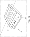
- base 10 may include solar cells 34 (see FIG. 12 ), batteries, or other features designed to supply electrical power without connection to electrical mains and without using any electrical cords C.
- control box CB electrically connected to base 10. If present, control box CB may be configured at least to receive wireless transmissions and convey signals to base 10. Of course, functionality of control box CB alternatively may be incorporated into base 10 itself.
- FIGS. 3-4 illustrate an exemplary cleaner 14.
- Cleaner 14 preferably is a robotic cleaner, although a suitably-outfitted hydraulic cleaner may be utilized instead.
- cleaner 14 may include body 38, pump 42, motive means 46, and electronics 50.
- the depicted version of cleaner 14 includes first and second electric motors 54 and 58, with the first motor 54 driving pump 42 and the second motor 58 driving motive means 46. More or fewer motors may, of course, be used instead.
- FIGS. 3-4 depict tracks 60 as part of motive means 46, wheels, brushes 61 (see FIGS. 5A-B ) or other equipment for moving cleaner 14 along a surface such as floor F or walls VW may be used additionally or instead.
- Battery 62 may be used to power electric motors of cleaner 14, such as first and second motors 54 and 58.
- Battery 62 also may power electronics 50, which typically include at least one or more computer processors or controllers. Accordingly, cleaner 14 may operate within water W of pool SP without any need for a cord or hose extending externally of body 38.
- Battery 62 advantageously is rechargeable (via induction or otherwise) at least when cleaner 14 is docked at base 10.
- Arrow A of FIG. 3 identifies a nominal forward direction of travel of cleaner 14.
- Region 66 consequently, may be deemed a front of cleaner 14, whereas region 70 may be considered the back of the cleaner 14.
- Present in region 66 may be handle 74 of debris filter 78, which may form part of, or be included in, body 38.
- Filter 78 is designed to retain debris vacuumed by cleaner 14 from water W.
- filter 78 may be configured to be removable from body 38 merely by grasping and pulling handle 74. Filter 78 likewise may be returned to body 38 by grasping handle 74 and sliding (pushing) the filter 78 into the body 38.
- handle 74 is presented as an uppermost part of body 38 above waterline WL notwithstanding that the majority of cleaner 10 may remain below waterline WL. With cleaner 10 in this position a human may easily reach down, grasp handle 74, and withdraw filter 78 from body 38 without entering pool SP himself or removing cleaner 14 from pool SP.
- filter 78 may be emptied and cleaned without any need for cleaner 14 to exit the pool SP. And as no hose or cord need be attached to its body 38, cleaner 14 may remain within pool SP as long as desired and operate autonomously, without tether, as needed. Stated differently, via its construction and capability of engaging with base 10, cleaner 14 may move within and vacuum pool SP, communicate with other devices, and have its debris filter 78 emptied without cleaner 14 ever exiting pool SP or being connected to an external hose or cord.
- FIG. 1 depicts component 22 of base 10 as positioned on deck D
- base 10 need not necessarily be so positioned.
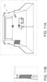
- FIGS. 6-7 show a base 10 located wholly below deck D, perhaps in a niche N of a wall VW. Cleaner 14 nevertheless may continue to engage base 10 as described earlier herein, continuing to present handle 74 above waterline WL as an uppermost part of body 38.
- deck D include a moveable section D1 facilitating access to handle 74.
- Section D1 may be hinged or configured for movement in any suitable manner.
- section D1 may be removed from deck D.
- no moveable section D1 need necessarily be present in deck D.
- FIGS. 8A-B illustrate another alternate placement of a base 10.
- base 10 is shown as having component 22 positioned within or on a skimmer SK of the pool SP.
- base 10 may be located wholly below a cover CV used to cover pool SP.
- base 10 may be designed to accommodate such covers CV without necessarily being connected to skimmers SK, however.
- base 10 is capable of transmitting and receiving radio frequency (RF) or other electronic signals wirelessly or via wire.
- Base 10 may provide instructions, information, and data to electronics 50 of cleaner 14, either when cleaner 14 is docked or otherwise.
- base 10 may receive instructions, information, and data from cleaner 14, again when cleaner 14 is docked or otherwise.
- RF radio frequency
- Base 10 additionally may communicate with control box CB of FIG. 1 if present.
- base 10 may communicate with other devices, including devices remote from pool SP. This communication may be direct or indirect, through a local-area network or wide-area network, via the Internet, or otherwise.
- Devices with which base 10 may communicate may include hand-held apparatus such as, but not limited to, smartphones, as well as other portable or non-portable devices. Bluetooth, Wi-Fi, or other communications protocols may be employed if desired.
- FIG. 9 conceptually illustrates certain communication options for base 10.
- Sensors present either in base 10 or cleaner 14 may supply information concerning, e.g ., the pool SP, characteristics of water W within pool SP, or the status of base 10 and cleaner 14 themselves.
- Base 10 may convey any or all of this information via wired or wireless communication link L for further processing, evaluation, assessment, storage, or otherwise.
- a sensor of cleaner 14 (or base 10) may identify when filter 78 needs emptying; this information may be conveyed to base 10 and thence to a smartphone or other device of the pool owner (or of a pool maintenance professional) for action.
- cleaner 14 or base 10 may illuminate a light or provide some other sort of visual, aural, or tactile indication, etc., that an event has occurred or status condition is achieved.
- base 10 may incorporate a camera trained at water W for sensing clarity or other aspects of the water W.
- FIG. 12 illustrates an exemplary "come home" button 82 on component 22 of base 10 which may be depressed by a human to cause base 10 to issue such an interrupt-type signal.
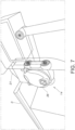
- cleaner 14 is shown as containing an optical sensor 86, and base 10 includes a laser or other light source 90. Assuming any other return conditions are satisfied, when optical sensor 86 detects light source 90, electronics 50 recognize that base 10 has been detected and is nearby (see FIG. 10A ). Programming of cleaner 14 may then cause the cleaner 14 to rotate from floor F to wall VW (see FIG. 10B ) and climb the wall VW in the forward direction in order to approach and align with base 10 (see FIG. 10C ). Thereafter cleaner 14 may engage base 10 (see FIG. 10D ) for docking. If the perimeter of pool SP has been mapped, cleaner 14 may already understand the approximate location of base 10, so the final alignment and docking may be able to occur relatively quickly.
- magnets may be used--both in base 10 and in cleaner 14--to retain cleaner 14 in place upon docking with base 10.
- a motor or other suitable mechanism could be employed in either base 10 or cleaner 14 to turn, or otherwise change the polarity of, its associated magnets so that the magnets either are attracted to or are repelled by the corresponding magnets of the other component. Attractive magnet will allow cleaner 14 to dock with base 10, whereas causing the magnet to repel will decouple cleaner 14 from dock 10.
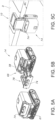
- FIGS. 11A-B illustrate one of many possibilities for inter-engaging cleaner 14 and base 10 for docking in which protrusions of tracks 60 fit into corresponding notches of base 10. In any event, cleaner 14 may be fixed into position relative to base 10.
- the disclosure includes the following items:
Abstract
Description
- This application claims priority to
French Patent Application No. 18 57496, filed August 14, 2018 - The present invention relates to systems, methods, and apparatus for cleaning liquid-containing vessels such as swimming pools and spas and more particularly, although not necessarily exclusively, to automatic swimming pool cleaners (APCs) configured to travel within swimming pools while removing debris from water thereof.
- APCs generally are well known. These cleaners often are categorized as either "hydraulic" or "robotic" (or "electric"), depending on the source of their motive power. Hydraulic cleaners, for example, typically use pressurized (or depressurized) water to effect their movement within pools, whereas robotic cleaners typically utilize an electric motor to cause their movement. Moreover, hydraulic cleaners frequently are subcategorized as either "pressure-side" or "suction-side" devices, with pressure-side cleaners receiving pressurized water output from an associated water-circulation pump and suction-side cleaners, by contrast, being connected to an inlet of the pump.
- Fluid-conveying hoses connect hydraulic cleaners with the water-circulation pumps. These hoses necessarily extend into the water of swimming pools and move about the pools as do the cleaners to which they are connected. The hoses often are considered to be unsightly and, at times, may present obstacles to swimmers or impede manual debris removal from pools.
- Robotic cleaners typically lack any such fluid-conveying hoses. However, because a reliable source of electricity is required to operate these types of cleaners, robotic APCs often include electrical cables connected directly or indirectly to their drive motors. Like fluid-conveying hoses, the electrical cables may be unsightly and obstruct or impede certain pool-related activities.
- Debris evacuated from pools using suction-side hydraulic cleaners normally travels through the fluid-conveying hoses to filters remote from the cleaners. Consequently, many suction-side cleaners do not necessarily need to be removed from swimming pools to discard the filtered debris. By contrast, most pressure-side hydraulic cleaners, as well as conventional robotic cleaners, contain filters within or carried by the bodies of the cleaners. In general, therefore, these types of APCs must be removed from pools in order to access their filters and empty the filters of debris. Removal of an APC from a pool is not always an easy task, however; withdrawing filters from wet bodies of APCs for emptying additionally disadvantageously exposes pool owners to water and debris.
-
U.S. Patent Application Publication No. 2006/0169322 of Torkelson discloses an early attempt at creating a docking system for a suction-side APC so as to conceal its fluid-conveying hose when the APC is not operating. The system utilizes a housing "preferably installed in the side of [a] swimming pool ... at the time of pool construction," see Torkelson, p. 6, ¶ 0079, as well as "a long storage tube" in which the fluid-conveying hose may be stored. A hydraulically-powered control assembly within the floor of the housing is employed to deploy and retract the hose. See id., p. 8, 0095, 0097. -
U.S. Patent Application Publication No. 2014/0263087 of Renaud, et al. , describes another docking system for use with APCs. The system includes a docking station for a robotic cleaner positioned at an edge of a swimming pool "such that a bottom end of the docking station extends into the water of the swimming pool and a top end extends above the water of the swimming pool." See Renaud, p. 3, ¶ 0026 (numerals omitted). The docking station may contain means for communicating with the APC and an electric cable for recharging a battery within the APC. The electric cable apparently remains attached to the APC during its use, as a hose swivel is deployed "to prevent tangling of the electric cable as the cleaner travels along the walls, floor and/or water line of the swimming pool." See id., ¶ 0028. - According to the Renaud application, the docking system additionally automatically empties debris from the APC into a collection chamber of the docking station. See id., p. 4, ¶ 0033. No explanation for how this emptying occurs is provided in the Renaud application. Likewise unexplained is how the collection chamber of the docking station itself is emptied.
- The present invention seeks to provide cleaning systems in which on-board filters of APCs may be removed easily for cleaning. Such easy removal, furthermore, may occur while a cleaner remains in a pool. Particularly beneficial is that the cleaner may present itself at the pool waterline in a manner allowing its filter to be grasped readily by someone positioned on a deck surrounding the pool.
- Also advantageous is that APCs of the present invention may lack entirely any hoses or electrical cords. Instead, the cleaners may utilize solely one or more on-board batteries for electrical power. Accordingly, the APCs need not be tethered in any way while in use, and no hoses or cords need obstruct or impede activities performed within the pool.
- Versions of the invention may include a docking station which an APC may engage. Such a docking station may, for example, allow recharging of the on-board batteries. It also may orient a cleaner body so that a handle of the filter of the cleaner is readily accessible for grasping. Like the docking station of the Renaud application, that of the invention may comprise a mechanism for communicating electronically with an APC at least while docked, if not also while operating within the pool. As but one example, the docking station may transmit a signal to a cleaner instructing the cleaner to approach the docking station for docking. Alternatively or additionally, the docking station may transmit a homing beacon allowing the APC to guide itself thereto.
- Docking stations may be located in any suitable places in, on, or about swimming pools. In some instances, a docking station may attach, temporarily or permanently, to a deck of a pool. In other cases, a docking station could connect to a skimmer of a pool or form part of a trolley. Also envisioned are situations in which a docking station is located in a wall niche or otherwise wholly below a deck of a pool.
- Systems of the invention hence may admit autonomous operation of cleaners within swimming pools, free of any external hoses, cords, or other tethers or restrictions. The cleaners may be pre-programmed if desired to control their actions and maneuvers within pools or signaled electronically to effect such control. Electronic communication certainly may occur when an APC is docked at a docking station. It conceivably also may occur wirelessly when the APC travels within an area proximate the docking station.
- Either the cleaner or the docking station (or both) may sense or measure characteristics of the pool or of the water contained therein. Information relating to the characteristics may be passed between the cleaner and the docking station. In some embodiments of the invention, the docking station may forward any or all of the information elsewhere, in any suitable wireless or wired manner.
- It thus is an optional, non-exclusive object of the present invention to provide swimming pool cleaners that may function without external hoses or cords.
- It is another optional, non-exclusive object of the present invention to provide systems permitting untethered operation of APCs within pools.
- It is also an optional, non-exclusive object of the present invention to provide cleaners capable of orienting their bodies at pool waterlines so as to present debris filters in manners facilitating their removal from the bodies.
- It is, moreover, an optional, non-exclusive object of the present invention to provide pool-cleaning systems including docking stations which APCs may engage.
- It is a further optional, non-exclusive object of the present invention to provide systems in which pool cleaners may communicate electronically with the docking stations or other external devices.
- Other objects, features, and advantages of the present invention will be apparent to persons skilled in the relevant field with reference to the remaining text and the drawings of this application.
-
-
FIG. 1 is an elevational, cut-away, partially schematicized illustration of a swimming pool in which components of a cleaning system of the present invention may operate. -
FIG. 2 is a conceptual illustration of an exemplary base or docking station which may be a component of the cleaning system ofFIG. 1 . -
FIG. 3 is a perspective view of an exemplary APC which likewise may be a component of the cleaning system ofFIG. 1 . -
FIG. 4 is an elevational, cut-away illustration of the APC ofFIG. 3 . -
FIGS. 5A-B are perspective views of another exemplary APC illustrating removal of an on-board debris filter. -
FIG. 5C depicts the APC ofFIGS. 5A-B docked at a docking station which may be a component of the cleaning system ofFIG. 1 . -
FIGS. 6-7 and8A-B are perspective, conceptual views of an alternate placement of a docking station which may be a component of the cleaning system ofFIG. 1 . -
FIG. 9 is a concept illustration of certain possible features of a docking station which may be a component of the cleaning system ofFIG. 1 . -
FIGS. 10A-D illustrate an exemplary approach of the present invention for guiding an APC to a docking station of the present invention. -
FIGS. 11A-B depict exemplary equipment of a docking system useful for docking an APC of the present invention. -
FIG. 12 is a perspective view of an exemplary docking station including, for example, solar cells for power generation. - Depicted in
FIG. 1 is swimming pool SP. As is conventional, pool SP may be filled with water W to a waterline WL and surrounded by a rim, coping, or deck D. Pool SP further may include bottom or floor F as well as one or more generally vertically-oriented walls VW. - Also shown in
FIG. 1 is anexemplary base 10.Base 10 may function as a docking station for an APC such as (but not limited to) cleaner 14 ofFIG. 3 . As illustrated inFIGS. 1-2 ,base 10 may be shaped in the form of the letter "L" with a generallyvertical component 18 and a generallyhorizontal component 22.Component 18 normally is configured to attach to deck D in any appropriate manner externally of water W, whereas at least part ofcomponent 22 preferably is positioned within pool SP below waterline WL. If desired,component 22 may include a generally planarrear face 26 for placement in contact with, or adjacent to, a wall VW.FIG. 2 additionally illustratessuction cups 30 protruding fromrear face 26 in contact with the wall VW to help stabilize the position ofbase 10. Persons skilled in the art will, however, recognize thatrear face 26 need not necessarily be planar and that suction cups 30 are optional, as other means of locatingbase 10 relative to pool SP may be employed. -
FIG. 1 illustratesbase 10 being connected to a source of electrical power EP (such as, but not limited to, electrical mains). Such connection may occur via one or more electrical cords C so as to power electronics and other equipment ofbase 10. Notably, any such electrical cords C may be located completely externally of pool SP, as the present invention preferably avoids any need for an electrical cord to be positioned in water W. Alternatively,base 10 may include solar cells 34 (seeFIG. 12 ), batteries, or other features designed to supply electrical power without connection to electrical mains and without using any electrical cords C. - Further depicted in
FIG. 1 is optional control box CB electrically connected tobase 10. If present, control box CB may be configured at least to receive wireless transmissions and convey signals tobase 10. Of course, functionality of control box CB alternatively may be incorporated intobase 10 itself. -
FIGS. 3-4 illustrate anexemplary cleaner 14.Cleaner 14 preferably is a robotic cleaner, although a suitably-outfitted hydraulic cleaner may be utilized instead. Like other robotic cleaners, cleaner 14 may includebody 38, pump 42, motive means 46, andelectronics 50. The depicted version of cleaner 14 includes first and secondelectric motors first motor 54 drivingpump 42 and thesecond motor 58 driving motive means 46. More or fewer motors may, of course, be used instead. AlthoughFIGS. 3-4 depicttracks 60 as part of motive means 46, wheels, brushes 61 (seeFIGS. 5A-B ) or other equipment for moving cleaner 14 along a surface such as floor F or walls VW may be used additionally or instead. - Shown in
FIG. 4 withinbody 38 is at least onebattery 62.Battery 62 may be used to power electric motors of cleaner 14, such as first andsecond motors Battery 62 also may powerelectronics 50, which typically include at least one or more computer processors or controllers. Accordingly, cleaner 14 may operate within water W of pool SP without any need for a cord or hose extending externally ofbody 38.Battery 62 advantageously is rechargeable (via induction or otherwise) at least when cleaner 14 is docked atbase 10. - Arrow A of
FIG. 3 identifies a nominal forward direction of travel of cleaner 14.Region 66, consequently, may be deemed a front of cleaner 14, whereasregion 70 may be considered the back of the cleaner 14. Present inregion 66 may be handle 74 ofdebris filter 78, which may form part of, or be included in,body 38.Filter 78 is designed to retain debris vacuumed by cleaner 14 from water W. - As illustrated particularly in
FIGS. 5A-B in connection with asimilar cleaner 14,filter 78 may be configured to be removable frombody 38 merely by grasping and pullinghandle 74.Filter 78 likewise may be returned tobody 38 by graspinghandle 74 and sliding (pushing) thefilter 78 into thebody 38. Hence, if cleaner 14 engagesbase 10 as shown inFIG. 5C , handle 74 is presented as an uppermost part ofbody 38 above waterline WL notwithstanding that the majority of cleaner 10 may remain below waterline WL. With cleaner 10 in this position a human may easily reach down, grasphandle 74, and withdrawfilter 78 frombody 38 without entering pool SP himself or removing cleaner 14 from pool SP. - In this way, filter 78 may be emptied and cleaned without any need for cleaner 14 to exit the pool SP. And as no hose or cord need be attached to its
body 38, cleaner 14 may remain within pool SP as long as desired and operate autonomously, without tether, as needed. Stated differently, via its construction and capability of engaging withbase 10, cleaner 14 may move within and vacuum pool SP, communicate with other devices, and have itsdebris filter 78 emptied without cleaner 14 ever exiting pool SP or being connected to an external hose or cord. - Although
FIG. 1 depictscomponent 22 ofbase 10 as positioned on deck D,base 10 need not necessarily be so positioned.FIGS. 6-7 , for example, show a base 10 located wholly below deck D, perhaps in a niche N of a wall VW.Cleaner 14 nevertheless may continue to engagebase 10 as described earlier herein, continuing to presenthandle 74 above waterline WL as an uppermost part ofbody 38. Contemplated inFIGS. 6-7 is that deck D include a moveable section D1 facilitating access to handle 74. Section D1 may be hinged or configured for movement in any suitable manner. Alternatively, section D1 may be removed from deck D. Yet alternatively, no moveable section D1 need necessarily be present in deck D. -
FIGS. 8A-B illustrate another alternate placement of abase 10. In thisinstance base 10 is shown as havingcomponent 22 positioned within or on a skimmer SK of the pool SP. In this manner,base 10 may be located wholly below a cover CV used to cover pool SP. Persons skilled in the art understand thatbase 10 may be designed to accommodate such covers CV without necessarily being connected to skimmers SK, however. - Beneficially,
base 10 is capable of transmitting and receiving radio frequency (RF) or other electronic signals wirelessly or via wire.Base 10 may provide instructions, information, and data toelectronics 50 of cleaner 14, either when cleaner 14 is docked or otherwise. Likewise,base 10 may receive instructions, information, and data from cleaner 14, again when cleaner 14 is docked or otherwise. -
Base 10 additionally may communicate with control box CB ofFIG. 1 if present. Alternatively or additionally,base 10 may communicate with other devices, including devices remote from pool SP. This communication may be direct or indirect, through a local-area network or wide-area network, via the Internet, or otherwise. Devices with whichbase 10 may communicate may include hand-held apparatus such as, but not limited to, smartphones, as well as other portable or non-portable devices. Bluetooth, Wi-Fi, or other communications protocols may be employed if desired. -
FIG. 9 conceptually illustrates certain communication options forbase 10. Sensors present either inbase 10 or cleaner 14 (or in both) may supply information concerning, e.g., the pool SP, characteristics of water W within pool SP, or the status ofbase 10 and cleaner 14 themselves.Base 10 may convey any or all of this information via wired or wireless communication link L for further processing, evaluation, assessment, storage, or otherwise. As but one example, a sensor of cleaner 14 (or base 10) may identify whenfilter 78 needs emptying; this information may be conveyed tobase 10 and thence to a smartphone or other device of the pool owner (or of a pool maintenance professional) for action. Alternatively or additionally, cleaner 14 orbase 10 may illuminate a light or provide some other sort of visual, aural, or tactile indication, etc., that an event has occurred or status condition is achieved. In some versions of the invention,base 10 may incorporate a camera trained at water W for sensing clarity or other aspects of the water W. - Included as inventive concepts herein are methods of guiding cleaner 14 to
base 10.Electronics 50 of cleaner 14 may, for example, be programmed to seekbase 10 after a designated time period has elapsed, a sensor indicatesfilter 78 is full, a sensor indicates pool SP contains swimmers, or otherwise. An interrupt-type signal received by an operating cleaner 14 similarly could cause the cleaner 14 to seekbase 10.FIG. 12 illustrates an exemplary "come home"button 82 oncomponent 22 ofbase 10 which may be depressed by a human to causebase 10 to issue such an interrupt-type signal. - In
FIGS. 10A-D , cleaner 14 is shown as containing anoptical sensor 86, andbase 10 includes a laser or otherlight source 90. Assuming any other return conditions are satisfied, whenoptical sensor 86 detectslight source 90,electronics 50 recognize thatbase 10 has been detected and is nearby (seeFIG. 10A ). Programming of cleaner 14 may then cause the cleaner 14 to rotate from floor F to wall VW (seeFIG. 10B ) and climb the wall VW in the forward direction in order to approach and align with base 10 (seeFIG. 10C ). Thereafter cleaner 14 may engage base 10 (seeFIG. 10D ) for docking. If the perimeter of pool SP has been mapped, cleaner 14 may already understand the approximate location ofbase 10, so the final alignment and docking may be able to occur relatively quickly. - In some embodiments of these systems, magnets may be used--both in
base 10 and in cleaner 14--to retain cleaner 14 in place upon docking withbase 10. A motor or other suitable mechanism conceivably could be employed in eitherbase 10 or cleaner 14 to turn, or otherwise change the polarity of, its associated magnets so that the magnets either are attracted to or are repelled by the corresponding magnets of the other component. Attractive magnet will allow cleaner 14 to dock withbase 10, whereas causing the magnet to repel will decouple cleaner 14 fromdock 10. - In other embodiments, electrical, mechanical, or electro-mechanical latching or locking mechanisms may be used.
FIGS. 11A-B illustrate one of many possibilities forinter-engaging cleaner 14 andbase 10 for docking in which protrusions oftracks 60 fit into corresponding notches ofbase 10. In any event, cleaner 14 may be fixed into position relative tobase 10. - Aspects of the present invention are not intended to be mutually exclusive, exhaustive, or restrictive in any way, and the invention is not limited to these example embodiments but rather encompasses all possible modifications and variations within the scope of any claims ultimately issued in connection with the invention (and their equivalents). For avoidance of doubt, any combination of features not physically impossible or expressly identified as non-combinable herein may be within the scope of the invention.
- The entire contents of the Torkelson and Renaud applications are incorporated herein by this reference. Further, although applicant has described systems for use in cleaning swimming pools, persons skilled in the relevant field will recognize that the present invention conceivably may be employed in other manners as well. Finally, references to "pools" and "swimming pools" herein may also refer to spas or other water containing vessels used for recreation or therapy and for which cleaning is needed or desired.
- The disclosure includes the following items:
- 1. A swimming pool cleaning system comprising:
- a. a base configured for attachment to a swimming pool having a waterline; and
- b. a cleaner (i) comprising a body, motive means, and a debris filter and (ii) configured to dock with the base so that (A) at least a portion of the debris filter extends above the waterline and (B) at least a portion of the body extends below the waterline.
- 2. A swimming pool cleaning system according to item 1 in which the debris filter comprises a handle extending above the waterline when the cleaner is docked with the base.
- 3. A swimming pool cleaning system according to item 1 in which the cleaner further comprises an on-board power supply and lacks any external electrical cord.
- 4. A swimming pool cleaning system according to item 3 in which the cleaner also lacks any external fluid-conveying hose.
- 5. A swimming pool cleaning system according to item 3 in which the on-board power supply comprises a rechargeable battery.
- 6. A swimming pool cleaning system according to item 5 in which the base is configured to recharge the rechargeable battery when the cleaner is docked.
- 7. A swimming pool cleaning system according to item 1 in which the base comprises means for supplying a homing beacon and the cleaner further comprises a detector for detecting the homing beacon.
- 8. An automatic swimming pool cleaner defining a front region and comprising:
- a. a body;
- b. an electric motor;
- c. motive means driven by the electric motor; and
- d. a filter (i) configured to be positioned at least partially in the body, (ii) comprising a handle located in the front region, and (iii) removable from the body by grasping and pulling the handle.
- 9. An automatic swimming pool cleaner according to cl item aim 7 in which the body lacks any external hose or electrical code, further comprising a source of electricity at least partially within the body for supplying electricity to the electric motor.
- 10. An automatic swimming pool cleaner according to item 9 in which the source of electricity is a rechargeable battery.
- 11. An automatic swimming pool cleaner according to
item 10 in which the motive means comprises a track. - 12. An automatic swimming pool cleaner according to item 11 in which the track comprises protrusions configured to fit into notches of a base.
- 13. A method of cleaning a swimming pool having a floor, a wall, and a waterline, comprising:
- a. causing an automatic swimming pool cleaner to travel untethered along the floor while vacuuming debris into an on-board filter; and
- b. causing the automatic swimming pool cleaner to climb the wall and dock with a docking station in an orientation such that at least part of the on-board filter is above the waterline and at least part of a body of the automatic swimming pool cleaner is below the waterline.
- 14. A method of cleaning a swimming pool according to item 13 further comprising removing the on-board filter from the automatic swimming pool cleaner.
- 15. A method of cleaning a swimming pool according to
item 14 further comprising cleaning the filter and reinserting the filter into the automatic swimming pool cleaner. - 16. A method of cleaning a swimming pool according to item 15 further comprising causing the automatic swimming pool cleaner to disengage from the docking station.
- 17. A method of cleaning a swimming pool according to item 13 in which each of the automatic swimming pool cleaner and the docking station comprises a magnet.
- 18. A method of cleaning a swimming pool according to item 17 in which the magnet of the automatic swimming pool cleaner engages the magnet of the docking station in an attractive manner to dock the automatic swimming pool cleaner with the docking station.
- 19. A method of cleaning a swimming pool according to item 16 in which (i) each of the automatic swimming pool cleaner and the docking station comprises a magnet and (ii) the act of causing the automatic swimming pool cleaner to disengage from the docket station comprises causing a change of polarity of either the magnet of the automatic swimming pool cleaner or the magnet of the docking station so as to repel the other magnet.
- 20. A swimming pool cleaning system according to item 1 in which the base is configured for attachment to at least one of a deck of the swimming pool, a skimmer of the swimming pool, or a wall of the swimming pool.
- 21. A swimming pool cleaning system according to item 20 in which the base is configured for removable attachment to at least one of the deck, the skimmer, or the wall.
- 22. A system for cleaning a swimming pool having a waterline, comprising:
- a. a trolley comprising a base; and
- b. a cleaner (i) comprising a body, motive means, and a debris filter and (ii) configured to dock with the base so that (A) at least a portion of the debris filter extends above the waterline and (B) at least a portion of the body extends below the waterline.
Claims (15)
- An automatic swimming pool cleaner adapted to travel under its own power within the swimming pool while vacuuming debris into an on-board filter,
wherein the automatic swimming pool cleaner is adapted for (i) sensing information regarding when the on-board filter should be emptied, (ii) conveying the sensed information to a device of a human external to the automatic swimming pool cleaner, (iii) based on the sensed information, climbing the wall under its own power at least to the waterline to facilitate emptying of the on-board filter; and (iv) emptying the on-board filter. - A swimming pool cleaner, preferably according to claim 1, comprising:
(A) a body lacking any external electrical cord, (B) motive means configured to cause the body to travel untethered within a swimming pool having a waterline, and (C) a debris filter, wherein the cleaner is configured to dock with a base attached to the swimming pool so that (A) at least a portion of the debris filter extends above the waterline and (B) at least a portion of the body extends below the waterline. - A swimming pool cleaner according to claim 1 or 2 in which the debris filter comprises a handle extending above the waterline when the cleaner is docked with the base.
- A swimming pool cleaner according to claim 1 or 2 in which the cleaner further comprises an on-board power supply.
- A swimming pool cleaner according to any of claims 1 to 4 in which the cleaner also lacks any external fluid-conveying hose, preferably in which the on-board power supply comprises a rechargeable battery.
- A swimming pool cleaning system comprising:a. a base configured for attachment to a swimming pool having a waterline; andb. a cleaner (i), preferably according to any of claims 1 to 5, comprising (A) a body lacking any external electrical cord, (B) motive means configured to cause the body to travel untethered within the swimming pool, and (C) a debris filter and (ii) configured to dock with the base so that (A) at least a portion of the debris filter extends above the waterline and (B) at least a portion of the body extends below the waterline.
- A swimming pool cleaning system according to claim 6 in which the debris filter comprises a handle extending above the waterline when the cleaner is docked with the base.
- A swimming pool cleaning system according to claim 6 in which the cleaner further comprises an on-board power supply.
- A swimming pool cleaning system according to claim 8 in which the cleaner also lacks any external fluid-conveying hose.
- A swimming pool cleaning system according to claim 8 in which the on-board power supply comprises a rechargeable battery.
- A swimming pool cleaning system according to claim 10 in which the base is configured to recharge the rechargeable battery when the cleaner is docked.
- A swimming pool cleaning system according to claim 6 in which the base comprises means for supplying a homing beacon and the cleaner further comprises a detector for detecting the homing beacon.
- A swimming pool cleaning system according to claim 6 in which the base is configured for attachment to at least one of a deck of the swimming pool, a skimmer of the swimming pool, or a wall of the swimming pool.
- A swimming pool cleaning system according to claim 13 in which the base is configured for removable attachment to at least one of the deck, the skimmer, or the wall.
- A method of cleaning a swimming pool having a wall and a waterline, comprising:a. causing an automatic swimming pool cleaner to travel under its own power within the swimming pool while vacuuming debris into an on-board filter, the automatic swimming pool cleaner (i) sensing information regarding when the on-board filter should be emptied, (ii) conveying the sensed information to a device of a human external to the automatic swimming pool cleaner, and (iii) based on the sensed information, climbing the wall under its own power at least to the waterline to facilitate emptying of the on-board filter;b. receiving the sensed information at the device of the human; andc. emptying the on-board filter.
Applications Claiming Priority (3)
| Application Number | Priority Date | Filing Date | Title |
|---|---|---|---|
| FR1857496 | 2018-08-14 | ||
| EP19779975.2A EP3837408B1 (en) | 2018-08-14 | 2019-08-14 | Autonomous cleaning systems for swimming pools |
| PCT/IB2019/056914 WO2020035810A1 (en) | 2018-08-14 | 2019-08-14 | Autonomous cleaning systems principally for swimming pools |
Related Parent Applications (2)
| Application Number | Title | Priority Date | Filing Date |
|---|---|---|---|
| EP19779975.2A Division EP3837408B1 (en) | 2018-08-14 | 2019-08-14 | Autonomous cleaning systems for swimming pools |
| EP19779975.2A Division-Into EP3837408B1 (en) | 2018-08-14 | 2019-08-14 | Autonomous cleaning systems for swimming pools |
Publications (2)
| Publication Number | Publication Date |
|---|---|
| EP4245947A2 true EP4245947A2 (en) | 2023-09-20 |
| EP4245947A3 EP4245947A3 (en) | 2024-04-03 |
Family
ID=68104687
Family Applications (2)
| Application Number | Title | Priority Date | Filing Date |
|---|---|---|---|
| EP19779975.2A Active EP3837408B1 (en) | 2018-08-14 | 2019-08-14 | Autonomous cleaning systems for swimming pools |
| EP23190735.3A Pending EP4245947A3 (en) | 2018-08-14 | 2019-08-14 | Autonomous cleaning systems for swimming pools |
Family Applications Before (1)
| Application Number | Title | Priority Date | Filing Date |
|---|---|---|---|
| EP19779975.2A Active EP3837408B1 (en) | 2018-08-14 | 2019-08-14 | Autonomous cleaning systems for swimming pools |
Country Status (5)
| Country | Link |
|---|---|
| US (2) | US10865581B2 (en) |
| EP (2) | EP3837408B1 (en) |
| AU (2) | AU2019322204B2 (en) |
| ES (1) | ES2962626T3 (en) |
| WO (1) | WO2020035810A1 (en) |
Families Citing this family (9)
| Publication number | Priority date | Publication date | Assignee | Title |
|---|---|---|---|---|
| US10927558B2 (en) * | 2018-04-26 | 2021-02-23 | Aqua Products, Inc. | Automatic pool cleaner with edge engagement assembly |
| AU2019322204B2 (en) | 2018-08-14 | 2022-12-01 | Zodiac Pool Care Europe | Autonomous cleaning systems principally for swimming pools |
| US20220189718A1 (en) | 2020-12-15 | 2022-06-16 | Zodiac Pool Systems Llc | Battery disconnection using water sensing for underwater battery-powered pool cleaning devices |
| AU2022208678A1 (en) * | 2021-01-13 | 2023-07-27 | Hayward Industries, Inc. | Mobile nozzles and associated systems for cleaning pools and spas |
| AU2022207745A1 (en) | 2021-01-14 | 2023-05-25 | Zodiac Pool Care Europe | Battery powered automatic swimming pool cleaners and associate components |
| US20220389731A1 (en) | 2021-06-07 | 2022-12-08 | Zodiac Pool Care Europe | Vessels such as swimming pools or spas omitting dedicated plumbed water-circulation systems |
| WO2022259058A1 (en) | 2021-06-07 | 2022-12-15 | Zodiac Pool Care Europe | Autonomous swimming pool cleaner |
| CN114753680A (en) * | 2022-05-23 | 2022-07-15 | 湖北一沐电子科技有限公司 | Swimming pool cleaning robot |
| WO2024057269A1 (en) * | 2022-09-15 | 2024-03-21 | Zodiac Pool Care Europe | Docking system for automatic swimming pool cleaner |
Citations (2)
| Publication number | Priority date | Publication date | Assignee | Title |
|---|---|---|---|---|
| US20060169322A1 (en) | 2003-12-12 | 2006-08-03 | Torkelson John E | Concealed automatic pool vacuum systems |
| US20140263087A1 (en) | 2013-03-15 | 2014-09-18 | Hayward Industries, Inc. | Swimming Pool Cleaner With Docking System And/Or Other Related Systems And Methods |
Family Cites Families (16)
| Publication number | Priority date | Publication date | Assignee | Title |
|---|---|---|---|---|
| IL156535A (en) * | 2003-06-19 | 2006-12-10 | Maytronics Ltd | Pool cleaning apparatus |
| FR2981970B1 (en) | 2011-10-27 | 2013-11-29 | Zodiac Pool Care Europe | IMMEREDE SURFACE CLEANER APPARATUS WITH SEMI-AUTOMATIC RETURN CONTROL |
| ES2538700T3 (en) * | 2012-05-30 | 2015-06-23 | Fabrizio Bernini | Swimming pool cleaning device |
| US9903130B2 (en) * | 2012-12-22 | 2018-02-27 | Maytronics Ltd. | Autonomous pool cleaning robot with an external docking station |
| EP2934934B1 (en) * | 2012-12-22 | 2018-05-02 | Maytronics Ltd. | Autonomous pool cleaning robot |
| US10533335B2 (en) * | 2013-10-13 | 2020-01-14 | Maytronics Ltd. | Autonomous pool cleaning robot |
| US9758980B2 (en) * | 2013-10-13 | 2017-09-12 | Maytronics Ltd. | System for extracting a pool cleaning robot |
| EP2835478B1 (en) * | 2014-01-07 | 2016-04-13 | Aquatron Robotic Technology Ltd. | Swimming pool cleaner |
| WO2016026059A1 (en) * | 2014-08-19 | 2016-02-25 | Mueller Peter A | Storage housing for pool robot |
| US10550594B2 (en) * | 2017-04-20 | 2020-02-04 | International Business Machines Corporation | Automated cleaning device |
| US10737395B2 (en) * | 2017-12-29 | 2020-08-11 | Irobot Corporation | Mobile robot docking systems and methods |
| KR102090649B1 (en) * | 2018-02-28 | 2020-03-18 | 엘지전자 주식회사 | Moving robot and Moving robot system |
| US10982456B2 (en) * | 2018-03-16 | 2021-04-20 | Maytronic Ltd. | Pool cleaning system |
| US10927558B2 (en) | 2018-04-26 | 2021-02-23 | Aqua Products, Inc. | Automatic pool cleaner with edge engagement assembly |
| US20200001723A1 (en) * | 2018-06-27 | 2020-01-02 | Aqua Products, Inc. | Charging System for Submersible Autonomous Vehicle with Rechargeable Battery |
| AU2019322204B2 (en) | 2018-08-14 | 2022-12-01 | Zodiac Pool Care Europe | Autonomous cleaning systems principally for swimming pools |
-
2019
- 2019-08-14 AU AU2019322204A patent/AU2019322204B2/en active Active
- 2019-08-14 EP EP19779975.2A patent/EP3837408B1/en active Active
- 2019-08-14 EP EP23190735.3A patent/EP4245947A3/en active Pending
- 2019-08-14 US US16/540,641 patent/US10865581B2/en active Active
- 2019-08-14 WO PCT/IB2019/056914 patent/WO2020035810A1/en unknown
- 2019-08-14 ES ES19779975T patent/ES2962626T3/en active Active
-
2020
- 2020-10-21 US US17/076,512 patent/US11299899B2/en active Active
-
2023
- 2023-02-08 AU AU2023200690A patent/AU2023200690B2/en active Active
Patent Citations (2)
| Publication number | Priority date | Publication date | Assignee | Title |
|---|---|---|---|---|
| US20060169322A1 (en) | 2003-12-12 | 2006-08-03 | Torkelson John E | Concealed automatic pool vacuum systems |
| US20140263087A1 (en) | 2013-03-15 | 2014-09-18 | Hayward Industries, Inc. | Swimming Pool Cleaner With Docking System And/Or Other Related Systems And Methods |
Also Published As
| Publication number | Publication date |
|---|---|
| EP4245947A3 (en) | 2024-04-03 |
| US10865581B2 (en) | 2020-12-15 |
| AU2023200690A1 (en) | 2023-03-09 |
| ES2962626T3 (en) | 2024-03-20 |
| AU2023200690B2 (en) | 2023-05-25 |
| EP3837408B1 (en) | 2023-10-04 |
| AU2019322204A1 (en) | 2021-02-25 |
| AU2019322204B2 (en) | 2022-12-01 |
| WO2020035810A1 (en) | 2020-02-20 |
| US20210032888A1 (en) | 2021-02-04 |
| US11299899B2 (en) | 2022-04-12 |
| EP3837408A1 (en) | 2021-06-23 |
| US20200056391A1 (en) | 2020-02-20 |
Similar Documents
| Publication | Publication Date | Title |
|---|---|---|
| AU2023200690B2 (en) | Autonomous cleaning systems principally for swimming pools | |
| EP2860329B1 (en) | Pool cleaning robot extraction system | |
| EP3540150B1 (en) | Pool cleaning system | |
| US6076226A (en) | Controlled self operated vacuum cleaning system | |
| US20160340922A1 (en) | Robotic pool cleaning apparatus | |
| US11629516B2 (en) | Swimming pool cleaning system with image capture device | |
| US20070067930A1 (en) | Cordless pool cleaning robot | |
| US11332222B2 (en) | Ramped pontoon for retrieving a pool cleaner | |
| US20220220762A1 (en) | Mobile Nozzles And Associated Systems For Cleaning Pools And Spas | |
| US20220389730A1 (en) | Filter extraction systems and techniques principally for autonomous swimming pool cleaners | |
| AU2022324790A1 (en) | Electromagnetic pool related platform battery charging |
Legal Events
| Date | Code | Title | Description |
|---|---|---|---|
| PUAI | Public reference made under article 153(3) epc to a published international application that has entered the european phase |
Free format text: ORIGINAL CODE: 0009012 |
|
| STAA | Information on the status of an ep patent application or granted ep patent |
Free format text: STATUS: REQUEST FOR EXAMINATION WAS MADE |
|
| 17P | Request for examination filed |
Effective date: 20230810 |
|
| AC | Divisional application: reference to earlier application |
Ref document number: 3837408 Country of ref document: EP Kind code of ref document: P |
|
| AK | Designated contracting states |
Kind code of ref document: A2 Designated state(s): AL AT BE BG CH CY CZ DE DK EE ES FI FR GB GR HR HU IE IS IT LI LT LU LV MC MK MT NL NO PL PT RO RS SE SI SK SM TR |
|
| RIN1 | Information on inventor provided before grant (corrected) |
Inventor name: DUFFAUT, SIMON Inventor name: LANCRY, ARNAUD |
|
| PUAL | Search report despatched |
Free format text: ORIGINAL CODE: 0009013 |
|
| AK | Designated contracting states |
Kind code of ref document: A3 Designated state(s): AL AT BE BG CH CY CZ DE DK EE ES FI FR GB GR HR HU IE IS IT LI LT LU LV MC MK MT NL NO PL PT RO RS SE SI SK SM TR |
|
| RIC1 | Information provided on ipc code assigned before grant |
Ipc: E04H 4/16 20060101AFI20240226BHEP |