EP4245885A2 - Catalyst solution for electroless plating devoid of an amine - Google Patents
Catalyst solution for electroless plating devoid of an amine Download PDFInfo
- Publication number
- EP4245885A2 EP4245885A2 EP23157540.8A EP23157540A EP4245885A2 EP 4245885 A2 EP4245885 A2 EP 4245885A2 EP 23157540 A EP23157540 A EP 23157540A EP 4245885 A2 EP4245885 A2 EP 4245885A2
- Authority
- EP
- European Patent Office
- Prior art keywords
- catalyst solution
- substrate
- electroless plating
- illustrative examples
- metal salt
- Prior art date
- Legal status (The legal status is an assumption and is not a legal conclusion. Google has not performed a legal analysis and makes no representation as to the accuracy of the status listed.)
- Pending
Links
Images



Classifications
-
- C—CHEMISTRY; METALLURGY
- C23—COATING METALLIC MATERIAL; COATING MATERIAL WITH METALLIC MATERIAL; CHEMICAL SURFACE TREATMENT; DIFFUSION TREATMENT OF METALLIC MATERIAL; COATING BY VACUUM EVAPORATION, BY SPUTTERING, BY ION IMPLANTATION OR BY CHEMICAL VAPOUR DEPOSITION, IN GENERAL; INHIBITING CORROSION OF METALLIC MATERIAL OR INCRUSTATION IN GENERAL
- C23C—COATING METALLIC MATERIAL; COATING MATERIAL WITH METALLIC MATERIAL; SURFACE TREATMENT OF METALLIC MATERIAL BY DIFFUSION INTO THE SURFACE, BY CHEMICAL CONVERSION OR SUBSTITUTION; COATING BY VACUUM EVAPORATION, BY SPUTTERING, BY ION IMPLANTATION OR BY CHEMICAL VAPOUR DEPOSITION, IN GENERAL
- C23C18/00—Chemical coating by decomposition of either liquid compounds or solutions of the coating forming compounds, without leaving reaction products of surface material in the coating; Contact plating
- C23C18/16—Chemical coating by decomposition of either liquid compounds or solutions of the coating forming compounds, without leaving reaction products of surface material in the coating; Contact plating by reduction or substitution, e.g. electroless plating
- C23C18/18—Pretreatment of the material to be coated
-
- C—CHEMISTRY; METALLURGY
- C23—COATING METALLIC MATERIAL; COATING MATERIAL WITH METALLIC MATERIAL; CHEMICAL SURFACE TREATMENT; DIFFUSION TREATMENT OF METALLIC MATERIAL; COATING BY VACUUM EVAPORATION, BY SPUTTERING, BY ION IMPLANTATION OR BY CHEMICAL VAPOUR DEPOSITION, IN GENERAL; INHIBITING CORROSION OF METALLIC MATERIAL OR INCRUSTATION IN GENERAL
- C23C—COATING METALLIC MATERIAL; COATING MATERIAL WITH METALLIC MATERIAL; SURFACE TREATMENT OF METALLIC MATERIAL BY DIFFUSION INTO THE SURFACE, BY CHEMICAL CONVERSION OR SUBSTITUTION; COATING BY VACUUM EVAPORATION, BY SPUTTERING, BY ION IMPLANTATION OR BY CHEMICAL VAPOUR DEPOSITION, IN GENERAL
- C23C18/00—Chemical coating by decomposition of either liquid compounds or solutions of the coating forming compounds, without leaving reaction products of surface material in the coating; Contact plating
- C23C18/16—Chemical coating by decomposition of either liquid compounds or solutions of the coating forming compounds, without leaving reaction products of surface material in the coating; Contact plating by reduction or substitution, e.g. electroless plating
- C23C18/18—Pretreatment of the material to be coated
- C23C18/20—Pretreatment of the material to be coated of organic surfaces, e.g. resins
- C23C18/28—Sensitising or activating
- C23C18/30—Activating or accelerating or sensitising with palladium or other noble metal
-
- C—CHEMISTRY; METALLURGY
- C23—COATING METALLIC MATERIAL; COATING MATERIAL WITH METALLIC MATERIAL; CHEMICAL SURFACE TREATMENT; DIFFUSION TREATMENT OF METALLIC MATERIAL; COATING BY VACUUM EVAPORATION, BY SPUTTERING, BY ION IMPLANTATION OR BY CHEMICAL VAPOUR DEPOSITION, IN GENERAL; INHIBITING CORROSION OF METALLIC MATERIAL OR INCRUSTATION IN GENERAL
- C23C—COATING METALLIC MATERIAL; COATING MATERIAL WITH METALLIC MATERIAL; SURFACE TREATMENT OF METALLIC MATERIAL BY DIFFUSION INTO THE SURFACE, BY CHEMICAL CONVERSION OR SUBSTITUTION; COATING BY VACUUM EVAPORATION, BY SPUTTERING, BY ION IMPLANTATION OR BY CHEMICAL VAPOUR DEPOSITION, IN GENERAL
- C23C18/00—Chemical coating by decomposition of either liquid compounds or solutions of the coating forming compounds, without leaving reaction products of surface material in the coating; Contact plating
- C23C18/16—Chemical coating by decomposition of either liquid compounds or solutions of the coating forming compounds, without leaving reaction products of surface material in the coating; Contact plating by reduction or substitution, e.g. electroless plating
- C23C18/1601—Process or apparatus
- C23C18/1603—Process or apparatus coating on selected surface areas
- C23C18/1607—Process or apparatus coating on selected surface areas by direct patterning
- C23C18/161—Process or apparatus coating on selected surface areas by direct patterning from plating step, e.g. inkjet
-
- C—CHEMISTRY; METALLURGY
- C23—COATING METALLIC MATERIAL; COATING MATERIAL WITH METALLIC MATERIAL; CHEMICAL SURFACE TREATMENT; DIFFUSION TREATMENT OF METALLIC MATERIAL; COATING BY VACUUM EVAPORATION, BY SPUTTERING, BY ION IMPLANTATION OR BY CHEMICAL VAPOUR DEPOSITION, IN GENERAL; INHIBITING CORROSION OF METALLIC MATERIAL OR INCRUSTATION IN GENERAL
- C23C—COATING METALLIC MATERIAL; COATING MATERIAL WITH METALLIC MATERIAL; SURFACE TREATMENT OF METALLIC MATERIAL BY DIFFUSION INTO THE SURFACE, BY CHEMICAL CONVERSION OR SUBSTITUTION; COATING BY VACUUM EVAPORATION, BY SPUTTERING, BY ION IMPLANTATION OR BY CHEMICAL VAPOUR DEPOSITION, IN GENERAL
- C23C18/00—Chemical coating by decomposition of either liquid compounds or solutions of the coating forming compounds, without leaving reaction products of surface material in the coating; Contact plating
- C23C18/16—Chemical coating by decomposition of either liquid compounds or solutions of the coating forming compounds, without leaving reaction products of surface material in the coating; Contact plating by reduction or substitution, e.g. electroless plating
- C23C18/52—Chemical coating by decomposition of either liquid compounds or solutions of the coating forming compounds, without leaving reaction products of surface material in the coating; Contact plating by reduction or substitution, e.g. electroless plating using reducing agents for coating with metallic material not provided for in a single one of groups C23C18/32 - C23C18/50
-
- B—PERFORMING OPERATIONS; TRANSPORTING
- B01—PHYSICAL OR CHEMICAL PROCESSES OR APPARATUS IN GENERAL
- B01J—CHEMICAL OR PHYSICAL PROCESSES, e.g. CATALYSIS OR COLLOID CHEMISTRY; THEIR RELEVANT APPARATUS
- B01J23/00—Catalysts comprising metals or metal oxides or hydroxides, not provided for in group B01J21/00
- B01J23/38—Catalysts comprising metals or metal oxides or hydroxides, not provided for in group B01J21/00 of noble metals
- B01J23/40—Catalysts comprising metals or metal oxides or hydroxides, not provided for in group B01J21/00 of noble metals of the platinum group metals
- B01J23/44—Palladium
-
- B—PERFORMING OPERATIONS; TRANSPORTING
- B01—PHYSICAL OR CHEMICAL PROCESSES OR APPARATUS IN GENERAL
- B01J—CHEMICAL OR PHYSICAL PROCESSES, e.g. CATALYSIS OR COLLOID CHEMISTRY; THEIR RELEVANT APPARATUS
- B01J31/00—Catalysts comprising hydrides, coordination complexes or organic compounds
- B01J31/02—Catalysts comprising hydrides, coordination complexes or organic compounds containing organic compounds or metal hydrides
- B01J31/0201—Oxygen-containing compounds
-
- B—PERFORMING OPERATIONS; TRANSPORTING
- B01—PHYSICAL OR CHEMICAL PROCESSES OR APPARATUS IN GENERAL
- B01J—CHEMICAL OR PHYSICAL PROCESSES, e.g. CATALYSIS OR COLLOID CHEMISTRY; THEIR RELEVANT APPARATUS
- B01J31/00—Catalysts comprising hydrides, coordination complexes or organic compounds
- B01J31/02—Catalysts comprising hydrides, coordination complexes or organic compounds containing organic compounds or metal hydrides
- B01J31/0201—Oxygen-containing compounds
- B01J31/0204—Ethers
-
- B—PERFORMING OPERATIONS; TRANSPORTING
- B01—PHYSICAL OR CHEMICAL PROCESSES OR APPARATUS IN GENERAL
- B01J—CHEMICAL OR PHYSICAL PROCESSES, e.g. CATALYSIS OR COLLOID CHEMISTRY; THEIR RELEVANT APPARATUS
- B01J31/00—Catalysts comprising hydrides, coordination complexes or organic compounds
- B01J31/02—Catalysts comprising hydrides, coordination complexes or organic compounds containing organic compounds or metal hydrides
- B01J31/0201—Oxygen-containing compounds
- B01J31/0205—Oxygen-containing compounds comprising carbonyl groups or oxygen-containing derivatives, e.g. acetals, ketals, cyclic peroxides
- B01J31/0208—Ketones or ketals
-
- B—PERFORMING OPERATIONS; TRANSPORTING
- B01—PHYSICAL OR CHEMICAL PROCESSES OR APPARATUS IN GENERAL
- B01J—CHEMICAL OR PHYSICAL PROCESSES, e.g. CATALYSIS OR COLLOID CHEMISTRY; THEIR RELEVANT APPARATUS
- B01J31/00—Catalysts comprising hydrides, coordination complexes or organic compounds
- B01J31/16—Catalysts comprising hydrides, coordination complexes or organic compounds containing coordination complexes
- B01J31/22—Organic complexes
- B01J31/2204—Organic complexes the ligands containing oxygen or sulfur as complexing atoms
- B01J31/2208—Oxygen, e.g. acetylacetonates
- B01J31/2226—Anionic ligands, i.e. the overall ligand carries at least one formal negative charge
-
- C—CHEMISTRY; METALLURGY
- C23—COATING METALLIC MATERIAL; COATING MATERIAL WITH METALLIC MATERIAL; CHEMICAL SURFACE TREATMENT; DIFFUSION TREATMENT OF METALLIC MATERIAL; COATING BY VACUUM EVAPORATION, BY SPUTTERING, BY ION IMPLANTATION OR BY CHEMICAL VAPOUR DEPOSITION, IN GENERAL; INHIBITING CORROSION OF METALLIC MATERIAL OR INCRUSTATION IN GENERAL
- C23C—COATING METALLIC MATERIAL; COATING MATERIAL WITH METALLIC MATERIAL; SURFACE TREATMENT OF METALLIC MATERIAL BY DIFFUSION INTO THE SURFACE, BY CHEMICAL CONVERSION OR SUBSTITUTION; COATING BY VACUUM EVAPORATION, BY SPUTTERING, BY ION IMPLANTATION OR BY CHEMICAL VAPOUR DEPOSITION, IN GENERAL
- C23C18/00—Chemical coating by decomposition of either liquid compounds or solutions of the coating forming compounds, without leaving reaction products of surface material in the coating; Contact plating
- C23C18/16—Chemical coating by decomposition of either liquid compounds or solutions of the coating forming compounds, without leaving reaction products of surface material in the coating; Contact plating by reduction or substitution, e.g. electroless plating
- C23C18/1601—Process or apparatus
- C23C18/1603—Process or apparatus coating on selected surface areas
-
- C—CHEMISTRY; METALLURGY
- C23—COATING METALLIC MATERIAL; COATING MATERIAL WITH METALLIC MATERIAL; CHEMICAL SURFACE TREATMENT; DIFFUSION TREATMENT OF METALLIC MATERIAL; COATING BY VACUUM EVAPORATION, BY SPUTTERING, BY ION IMPLANTATION OR BY CHEMICAL VAPOUR DEPOSITION, IN GENERAL; INHIBITING CORROSION OF METALLIC MATERIAL OR INCRUSTATION IN GENERAL
- C23C—COATING METALLIC MATERIAL; COATING MATERIAL WITH METALLIC MATERIAL; SURFACE TREATMENT OF METALLIC MATERIAL BY DIFFUSION INTO THE SURFACE, BY CHEMICAL CONVERSION OR SUBSTITUTION; COATING BY VACUUM EVAPORATION, BY SPUTTERING, BY ION IMPLANTATION OR BY CHEMICAL VAPOUR DEPOSITION, IN GENERAL
- C23C18/00—Chemical coating by decomposition of either liquid compounds or solutions of the coating forming compounds, without leaving reaction products of surface material in the coating; Contact plating
- C23C18/16—Chemical coating by decomposition of either liquid compounds or solutions of the coating forming compounds, without leaving reaction products of surface material in the coating; Contact plating by reduction or substitution, e.g. electroless plating
- C23C18/1601—Process or apparatus
- C23C18/1603—Process or apparatus coating on selected surface areas
- C23C18/1607—Process or apparatus coating on selected surface areas by direct patterning
- C23C18/1608—Process or apparatus coating on selected surface areas by direct patterning from pretreatment step, i.e. selective pre-treatment
-
- C—CHEMISTRY; METALLURGY
- C23—COATING METALLIC MATERIAL; COATING MATERIAL WITH METALLIC MATERIAL; CHEMICAL SURFACE TREATMENT; DIFFUSION TREATMENT OF METALLIC MATERIAL; COATING BY VACUUM EVAPORATION, BY SPUTTERING, BY ION IMPLANTATION OR BY CHEMICAL VAPOUR DEPOSITION, IN GENERAL; INHIBITING CORROSION OF METALLIC MATERIAL OR INCRUSTATION IN GENERAL
- C23C—COATING METALLIC MATERIAL; COATING MATERIAL WITH METALLIC MATERIAL; SURFACE TREATMENT OF METALLIC MATERIAL BY DIFFUSION INTO THE SURFACE, BY CHEMICAL CONVERSION OR SUBSTITUTION; COATING BY VACUUM EVAPORATION, BY SPUTTERING, BY ION IMPLANTATION OR BY CHEMICAL VAPOUR DEPOSITION, IN GENERAL
- C23C18/00—Chemical coating by decomposition of either liquid compounds or solutions of the coating forming compounds, without leaving reaction products of surface material in the coating; Contact plating
- C23C18/16—Chemical coating by decomposition of either liquid compounds or solutions of the coating forming compounds, without leaving reaction products of surface material in the coating; Contact plating by reduction or substitution, e.g. electroless plating
- C23C18/1601—Process or apparatus
- C23C18/1633—Process of electroless plating
- C23C18/1689—After-treatment
- C23C18/1692—Heat-treatment
-
- C—CHEMISTRY; METALLURGY
- C23—COATING METALLIC MATERIAL; COATING MATERIAL WITH METALLIC MATERIAL; CHEMICAL SURFACE TREATMENT; DIFFUSION TREATMENT OF METALLIC MATERIAL; COATING BY VACUUM EVAPORATION, BY SPUTTERING, BY ION IMPLANTATION OR BY CHEMICAL VAPOUR DEPOSITION, IN GENERAL; INHIBITING CORROSION OF METALLIC MATERIAL OR INCRUSTATION IN GENERAL
- C23C—COATING METALLIC MATERIAL; COATING MATERIAL WITH METALLIC MATERIAL; SURFACE TREATMENT OF METALLIC MATERIAL BY DIFFUSION INTO THE SURFACE, BY CHEMICAL CONVERSION OR SUBSTITUTION; COATING BY VACUUM EVAPORATION, BY SPUTTERING, BY ION IMPLANTATION OR BY CHEMICAL VAPOUR DEPOSITION, IN GENERAL
- C23C18/00—Chemical coating by decomposition of either liquid compounds or solutions of the coating forming compounds, without leaving reaction products of surface material in the coating; Contact plating
- C23C18/16—Chemical coating by decomposition of either liquid compounds or solutions of the coating forming compounds, without leaving reaction products of surface material in the coating; Contact plating by reduction or substitution, e.g. electroless plating
- C23C18/18—Pretreatment of the material to be coated
- C23C18/1803—Pretreatment of the material to be coated of metallic material surfaces or of a non-specific material surfaces
- C23C18/1824—Pretreatment of the material to be coated of metallic material surfaces or of a non-specific material surfaces by chemical pretreatment
- C23C18/1827—Pretreatment of the material to be coated of metallic material surfaces or of a non-specific material surfaces by chemical pretreatment only one step pretreatment
- C23C18/1831—Use of metal, e.g. activation, sensitisation with noble metals
-
- C—CHEMISTRY; METALLURGY
- C23—COATING METALLIC MATERIAL; COATING MATERIAL WITH METALLIC MATERIAL; CHEMICAL SURFACE TREATMENT; DIFFUSION TREATMENT OF METALLIC MATERIAL; COATING BY VACUUM EVAPORATION, BY SPUTTERING, BY ION IMPLANTATION OR BY CHEMICAL VAPOUR DEPOSITION, IN GENERAL; INHIBITING CORROSION OF METALLIC MATERIAL OR INCRUSTATION IN GENERAL
- C23C—COATING METALLIC MATERIAL; COATING MATERIAL WITH METALLIC MATERIAL; SURFACE TREATMENT OF METALLIC MATERIAL BY DIFFUSION INTO THE SURFACE, BY CHEMICAL CONVERSION OR SUBSTITUTION; COATING BY VACUUM EVAPORATION, BY SPUTTERING, BY ION IMPLANTATION OR BY CHEMICAL VAPOUR DEPOSITION, IN GENERAL
- C23C18/00—Chemical coating by decomposition of either liquid compounds or solutions of the coating forming compounds, without leaving reaction products of surface material in the coating; Contact plating
- C23C18/16—Chemical coating by decomposition of either liquid compounds or solutions of the coating forming compounds, without leaving reaction products of surface material in the coating; Contact plating by reduction or substitution, e.g. electroless plating
- C23C18/18—Pretreatment of the material to be coated
- C23C18/1803—Pretreatment of the material to be coated of metallic material surfaces or of a non-specific material surfaces
- C23C18/1824—Pretreatment of the material to be coated of metallic material surfaces or of a non-specific material surfaces by chemical pretreatment
- C23C18/1827—Pretreatment of the material to be coated of metallic material surfaces or of a non-specific material surfaces by chemical pretreatment only one step pretreatment
- C23C18/1834—Use of organic or inorganic compounds other than metals, e.g. activation, sensitisation with polymers
-
- C—CHEMISTRY; METALLURGY
- C23—COATING METALLIC MATERIAL; COATING MATERIAL WITH METALLIC MATERIAL; CHEMICAL SURFACE TREATMENT; DIFFUSION TREATMENT OF METALLIC MATERIAL; COATING BY VACUUM EVAPORATION, BY SPUTTERING, BY ION IMPLANTATION OR BY CHEMICAL VAPOUR DEPOSITION, IN GENERAL; INHIBITING CORROSION OF METALLIC MATERIAL OR INCRUSTATION IN GENERAL
- C23C—COATING METALLIC MATERIAL; COATING MATERIAL WITH METALLIC MATERIAL; SURFACE TREATMENT OF METALLIC MATERIAL BY DIFFUSION INTO THE SURFACE, BY CHEMICAL CONVERSION OR SUBSTITUTION; COATING BY VACUUM EVAPORATION, BY SPUTTERING, BY ION IMPLANTATION OR BY CHEMICAL VAPOUR DEPOSITION, IN GENERAL
- C23C18/00—Chemical coating by decomposition of either liquid compounds or solutions of the coating forming compounds, without leaving reaction products of surface material in the coating; Contact plating
- C23C18/16—Chemical coating by decomposition of either liquid compounds or solutions of the coating forming compounds, without leaving reaction products of surface material in the coating; Contact plating by reduction or substitution, e.g. electroless plating
- C23C18/18—Pretreatment of the material to be coated
- C23C18/20—Pretreatment of the material to be coated of organic surfaces, e.g. resins
- C23C18/2006—Pretreatment of the material to be coated of organic surfaces, e.g. resins by other methods than those of C23C18/22 - C23C18/30
- C23C18/2046—Pretreatment of the material to be coated of organic surfaces, e.g. resins by other methods than those of C23C18/22 - C23C18/30 by chemical pretreatment
- C23C18/2053—Pretreatment of the material to be coated of organic surfaces, e.g. resins by other methods than those of C23C18/22 - C23C18/30 by chemical pretreatment only one step pretreatment
- C23C18/206—Use of metal other than noble metals and tin, e.g. activation, sensitisation with metals
-
- C—CHEMISTRY; METALLURGY
- C23—COATING METALLIC MATERIAL; COATING MATERIAL WITH METALLIC MATERIAL; CHEMICAL SURFACE TREATMENT; DIFFUSION TREATMENT OF METALLIC MATERIAL; COATING BY VACUUM EVAPORATION, BY SPUTTERING, BY ION IMPLANTATION OR BY CHEMICAL VAPOUR DEPOSITION, IN GENERAL; INHIBITING CORROSION OF METALLIC MATERIAL OR INCRUSTATION IN GENERAL
- C23C—COATING METALLIC MATERIAL; COATING MATERIAL WITH METALLIC MATERIAL; SURFACE TREATMENT OF METALLIC MATERIAL BY DIFFUSION INTO THE SURFACE, BY CHEMICAL CONVERSION OR SUBSTITUTION; COATING BY VACUUM EVAPORATION, BY SPUTTERING, BY ION IMPLANTATION OR BY CHEMICAL VAPOUR DEPOSITION, IN GENERAL
- C23C18/00—Chemical coating by decomposition of either liquid compounds or solutions of the coating forming compounds, without leaving reaction products of surface material in the coating; Contact plating
- C23C18/16—Chemical coating by decomposition of either liquid compounds or solutions of the coating forming compounds, without leaving reaction products of surface material in the coating; Contact plating by reduction or substitution, e.g. electroless plating
- C23C18/18—Pretreatment of the material to be coated
- C23C18/20—Pretreatment of the material to be coated of organic surfaces, e.g. resins
- C23C18/2006—Pretreatment of the material to be coated of organic surfaces, e.g. resins by other methods than those of C23C18/22 - C23C18/30
- C23C18/2046—Pretreatment of the material to be coated of organic surfaces, e.g. resins by other methods than those of C23C18/22 - C23C18/30 by chemical pretreatment
- C23C18/2053—Pretreatment of the material to be coated of organic surfaces, e.g. resins by other methods than those of C23C18/22 - C23C18/30 by chemical pretreatment only one step pretreatment
- C23C18/2066—Use of organic or inorganic compounds other than metals, e.g. activation, sensitisation with polymers
-
- C—CHEMISTRY; METALLURGY
- C23—COATING METALLIC MATERIAL; COATING MATERIAL WITH METALLIC MATERIAL; CHEMICAL SURFACE TREATMENT; DIFFUSION TREATMENT OF METALLIC MATERIAL; COATING BY VACUUM EVAPORATION, BY SPUTTERING, BY ION IMPLANTATION OR BY CHEMICAL VAPOUR DEPOSITION, IN GENERAL; INHIBITING CORROSION OF METALLIC MATERIAL OR INCRUSTATION IN GENERAL
- C23C—COATING METALLIC MATERIAL; COATING MATERIAL WITH METALLIC MATERIAL; SURFACE TREATMENT OF METALLIC MATERIAL BY DIFFUSION INTO THE SURFACE, BY CHEMICAL CONVERSION OR SUBSTITUTION; COATING BY VACUUM EVAPORATION, BY SPUTTERING, BY ION IMPLANTATION OR BY CHEMICAL VAPOUR DEPOSITION, IN GENERAL
- C23C18/00—Chemical coating by decomposition of either liquid compounds or solutions of the coating forming compounds, without leaving reaction products of surface material in the coating; Contact plating
- C23C18/16—Chemical coating by decomposition of either liquid compounds or solutions of the coating forming compounds, without leaving reaction products of surface material in the coating; Contact plating by reduction or substitution, e.g. electroless plating
- C23C18/31—Coating with metals
-
- B—PERFORMING OPERATIONS; TRANSPORTING
- B01—PHYSICAL OR CHEMICAL PROCESSES OR APPARATUS IN GENERAL
- B01J—CHEMICAL OR PHYSICAL PROCESSES, e.g. CATALYSIS OR COLLOID CHEMISTRY; THEIR RELEVANT APPARATUS
- B01J2531/00—Additional information regarding catalytic systems classified in B01J31/00
- B01J2531/80—Complexes comprising metals of Group VIII as the central metal
- B01J2531/82—Metals of the platinum group
- B01J2531/824—Palladium
Definitions
- the present disclosure relates generally to bonding metal to a substrate, and more particularly, to formulations and methods for creating and using a catalyst solution for electroless plating on a substrate.
- An embodiment of the present disclosure provides a catalyst solution for electroless plating, wherein the catalyst solution is printable and devoid of an amine.
- the catalyst solution comprises a catalytic metal salt, a solvent, and an epoxy.
- Another embodiment of the present disclosure provides a method of directly writing a desired pattern of metal on a surface of a substrate.
- a printable catalyst solution devoid of an amine is selectively applied to a surface of a substrate in a desired pattern.
- the catalyst solution comprises a catalytic metal salt, a solvent, and an epoxy.
- the catalyst solution is dried in the desired pattern on the surface of the substrate.
- the substrate is electrolessly plated in a metal aqueous solution.
- the component comprises a substrate having a surface, a desired pattern of metal nanoparticles and epoxy on the surface of the substrate, and a metal film formed over only the desired pattern but not exposed portions of the surface of the substrate.
- the illustrative examples recognize and take into account one or more different considerations.
- the illustrative examples recognize and take into account that current methods of forming circuitry utilize lithography and masking techniques that increase manufacturing time, cost, and waste.
- the illustrative examples also recognize and take into account that conventional direct writing techniques for conductive traces may not provide sufficient conductivity for some applications.
- the illustrative examples also recognize and take into account that conventional metal trace deposition techniques cannot enable desired technologies.
- the illustrative examples present a method of forming a desired pattern on a substrate with a metal trace.
- the illustrative examples present a catalyst solution for electroless plating, wherein the catalyst solution is printable and devoid of an amine.
- the illustrative examples present a method of directly writing a desired pattern of metal on a surface of a substrate.
- Manufacturing environment 100 includes catalyst solution 102 for electroless plating 104.
- Catalyst solution 102 is printable 106 and devoid of an amine.
- Catalyst solution 102 is printable 106 based on material properties of catalyst solution 102.
- Catalyst solution 102 comprises catalytic metal salt 108, solvent 110, and epoxy 112. Catalyst solution 102 is non-amine-based but reduces metal ions in electroless plating 104. Catalytic metal salt 108 is solvent-soluble. In some illustrative examples, catalytic metal salt 108 comprises at least one of palladium, platinum, rhodium, iridium, osmium, ruthenium, copper, nickel, or silver. As used herein, the phrase "at least one of,” when used with a list of items, means different combinations of one or more of the listed items may be used and only one of each item in the list may be needed.
- “at least one of item A, item B, or item C” may include, without limitation, item A, item A and item B, or item B. This example also may include item A, item B, and item C or item B and item C. Of course, any combinations of these items may be present. In other examples, "at least one of” may be, for example, without limitation, two of item A; one of item B; and ten of item C; four of item B and seven of item C; or other suitable combinations.
- the item may be a particular object, thing, or a category. In other words, at least one of means any combination items and number of items may be used from the list but not all of the items in the list are required.
- catalytic metal salt 108 comprises at least one of palladium or platinum. In some illustrative examples, catalytic metal salt 108 comprises palladium acetate 114. In some illustrative examples, catalytic metal salt 108 is one of an acetate, a chloride, a sulfate, or a nitrate.
- Characteristics of catalytic metal salt 108 are selected to be printable 106. Diameters 115 of particles of catalytic metal salt 108 are selected to be printable 106 with a desired deposition method. In some illustrative examples, diameters 115 of particles of catalytic metal salt 108 are selected to promote formation of a metal layer in electroless plating 104. In some illustrative examples, diameters 115 of particles of catalytic metal salt 108 are smaller than a desired nozzle 130 diameter 132 of a direct write applicator 128. In some illustrative examples, catalytic metal salt 108 is selected based on a desired resistivity of the resulting metal pattern.
- Solvent 110 is selected based on the selection of epoxy 112 and catalytic metal salt 108. Solvent 110 is selected to place the selected epoxy 112 and the selected catalytic metal salt 108 into solution. In some illustrative examples, solvent 110 comprises at least one of methyl-ethyl-ketone 116, tetrahydrofuran 118, or toluene 120.
- catalyst solution 102 has a volume percentage of solvent 110 selected to provide viscosity 122 compatible with selected deposition equipment 126.
- deposition equipment 126 may also be referred to as direct write applicator 128.
- direct write processes can be described as "printing" conductive traces using metallic ink.
- deposition equipment 126 takes the form of aerosol jet 124. Aerosol jet 124 includes atomization and deposition. Atomization for aerosol jet 124 is selected from ultrasonic or pneumatic atomization.
- a deposition head for aerosol jet 124 can be a macro deposition head, a micro deposition head, or a wide head.
- a macro deposition head has nozzle/tip diameters in the range of 0.500 millimeters to 2.50 millimeters. In some illustrative examples, a macro deposition head has trace widths between 100 microns and 2000 microns. In some illustrative examples, a micro deposition head has nozzle/tip diameters in the range of 0.100 millimeters to 0.300 millimeters. In some illustrative examples, a micro deposition head has trace widths between 20 microns and 200 microns. In some illustrative examples, a wide head for aerosol jet 124 has a nozzle/tip width of 10 millimeters. In some illustrative examples, a trace thickness deposited by aerosol jet 124 is in the range of 2 micrometers to 3 micrometers per layer.
- catalyst solution 102 has a volume percentage of solvent 110 selected to provide viscosity 122 compatible with aerosol jet 124.
- viscosity 122 is between 25 centipoise and 125 centipoise to enable spray coating.
- catalytic metal salt 108 is dissolved in solvent 110 to form a first solution and epoxy 112 is mixed with solvent 110 separately to form a second solution. Afterwards, the first solution is added to the second solution to form a combination. In some illustrative examples, adding the first solution to the second solution forms catalyst solution 102. In some illustrative examples, additional solvent 110 is introduced to the combination to form catalyst solution 102. In some illustrative examples, additional solvent 110 is introduced to the combination to achieve a desired value for viscosity 122.
- additional solvent 110 is introduced to the combination to achieve a desired mass ratio in catalyst solution 102.
- catalyst solution 102 is applied to surface 140 of substrate 142 in desired pattern 134 by deposition equipment 126.
- deposition equipment 126 applies catalyst solution 102 at deposition speed 133 in the range of 20 millimeters/second to 40 millimeters/second.
- Desired pattern 134 takes any desirable form for utilizing the conductivity of catalyst solution 102 and metal film formed by electroless plating 104. In some illustrative examples, desired pattern 134 takes the form of conductive wiring. In some illustrative examples, desired pattern 134 takes the form of circuit 136. In some illustrative examples, desired pattern 134 is decorative 138. Desired pattern 134 is applied to surface 140 of substrate 142 by deposition equipment 126.
- Substrate 142 is a material in which conductivity of only portions of surface 140 is desirable. Substrate 142 takes any desirable form. By applying catalyst solution 102 and performing electroless plating 104, the conductivity of substrate 142 is manipulated. In some illustrative examples, substrate 142 comprises non-conductive material 144. In some illustrative examples, substrate 142 is formed of one of polymer 146 or composite 148. In some illustrative examples, substrate 142 takes the form of part 150. Part 150 is a component of a platform. The platform can take any desirable form. Although the illustrative examples for an illustrative embodiment below are described with respect to an aircraft, an illustrative embodiment may be applied to other types of platforms.
- the platform may be, for example, a mobile platform, a stationary platform, a land-based structure, an aquatic-based structure, and a space-based structure. More specifically, the platform, may be a surface ship, a tank, a personnel carrier, a train, a spacecraft, a space station, a satellite, a submarine, an automobile, a power plant, a bridge, a dam, a house, a manufacturing facility, a building, an electronic device such as a phone, computer, tablet, sensor, and other suitable platforms.
- substrate 142 can be a panel, a circuit, a faceplate, or any other desirable type of part.
- substrate 142 takes the form of film 152.
- Substrate 142 is formed in any desirable manner such that surface 140 has a roughness that enables directly depositing catalyst solution 102.
- Substrate 142 can be formed through molding, machining, or additive manufacturing 154.
- additive manufacturing equipment 156 is present in manufacturing environment 100.
- catalyst solution 102 is dried.
- epoxy 112 is dried and solvent 110 is driven off.
- epoxy 112 is heat curable 158 and epoxy 112 is dried and partially cured by applying heat.
- epoxy 112 comprises heat curable 158 such as E3710 or EC2290.
- epoxy 112 is UV curable 160.
- Drying is performed at a time and temperature to evaporate solvent 110 and dry epoxy 112. By only partially curing epoxy 112, active sites of the catalyst are maintained. In some illustrative examples, the drying is performed at a temperature in the range of 75 degrees Celsius to 135 degrees Celsius. In some illustrative examples, the drying is performed for a time in the range of 5 minutes to 30 minutes.
- metal aqueous solution 162 comprises at least one of nickel, cobalt, iron, or copper. In some illustrative examples, metal aqueous solution 162 comprises at least one of nickel, cobalt, iron, copper, gold, silver, palladium, platinum, rhodium, or ruthenium.
- the thickness of the metal film deposited during electroless plating 104 is controlled by modifying the temperature 166 and time 168 of electroless plating 104.
- the thickness of the metal film deposited during electroless plating 104 is affected by the type and amount of catalytic metal salt 108.
- catalyst solution 102 0.25 grams of palladium acetate 114 is dissolved in 20 milliliters methyl-ethyl-ketone 116 and then mixed until dissolved in solution. Separately, 2 grams of epoxy 112, such as EC3710 from 3M, and 60 grams of toluene 120 are combined. Afterwards, the palladium acetate 114 solution is added to the epoxy 112 solution. An additional amount of methyl-ethyl-ketone 116 can be added to achieve desired mass ratios. In one illustrative example, the resulting catalyst solution 102 comprises 0.25 grams of palladium acetate 114, 2 grams of epoxy 112, 150 grams of methyl-ethyl-ketone 116, and 60 grams of toluene 120.
- catalyst solution 102 0.25 grams of palladium acetate 114 is dissolved in 20 milliliters methyl-ethyl-ketone 116 and then mixed until dissolved in solution. Separately, 2 grams of epoxy 112, such as EC3710 from 3M, and 40 grams of tetrahydrofuran 118 are combined. Afterwards, the palladium acetate solution is added to the epoxy solution. An additional amount of methyl-ethyl-ketone 116 can be added to achieve desired mass ratios.
- the resulting catalyst solution 102 comprises 0.25 grams of palladium acetate 114, 2 grams of epoxy 112, 159 grams of methyl-ethyl-ketone 116, and 40 grams of tetrahydrofuran 118.
- Deposition of catalyst solution 102, drying of catalyst solution 102, and electroless plating 104 form a component comprising substrate 142 having surface 140, desired pattern 134 of metal nanoparticles and epoxy on surface 140 of substrate 142, and a metal film formed over only desired pattern 134 but not exposed portions of surface 140 of substrate 142.
- Deposition of catalyst solution 102 and electroless plating 104 can enable a variety of different technologies including embedded sensors, antennas, embedded lighting, electronic switches, wireless charging, decorative lighting, embedded heaters, and other technologies enabled by printed circuitry or printed metal wires.
- catalyst solution 102 is not meant to imply physical or architectural limitations to the manner in which an illustrative embodiment may be implemented.
- Other components in addition to or in place of the ones illustrated may be used. Some components may be unnecessary.
- the blocks are presented to illustrate some functional components. One or more of these blocks may be combined, divided, or combined and divided into different blocks when implemented in an illustrative embodiment.
- substrate 142 could have any desirable curvature.
- solvent 110 can take the form of another solvent other than methyl-ethyl-ketone 116, tetrahydrofuran 118, or toluene 120.
- Substrate 200 is an implementation of substrate 142 of Figure 1 .
- Substrate 200 can be formed using any desirable manufacturing technique that results in a desirable surface roughness for directly writing on surface 202.
- Substrate 200 can be formed using machining, molding, additive manufacturing, or any other desirable manufacturing method.
- Substrate 200 has surface 202 upon which catalyst solution 204 is applied 206.
- Surface 202 is an implementation of surface 140 of Figure 1 . Although surface 202 appears planar due to the block diagram illustration, surface 202 can have any desirable curvature. In some illustrative examples, surface 202 comprises at least one of a curved surface or a complex surface. Surface 202 has any desirable surface roughness.
- Catalyst solution 204 is an implementation of catalyst solution 102 of Figure 1 .
- Catalyst solution 204 is applied 206 using any desirable method.
- catalyst solution 204 is deposited using a direct write applicator.
- catalyst solution 204 is deposited using an aerosol jet.
- Desired pattern 208 can take any desirable form. In some illustrative examples, desired pattern 208 takes the form of circuitry. In some illustrative examples, desired pattern 208 is decorative.
- View 300 is a view of substrate 200 of Figure 2 in oven 301.
- View 300 is a view of drying catalyst solution 204 of Figure 2 in desired pattern 208 on surface 202 of substrate 200 within oven 301.
- oven 301 applies heat 302 to substrate 200 to dry catalyst solution 204 applied 206 in Figure 2 .
- Drying catalyst solution 204 in desired pattern 208 on surface 202 of substrate 200 drives off solvent 304 and dries the epoxy.
- Driving off solvent 304 forms catalytic metal salt and epoxy 306.
- the epoxy is dry in catalytic metal salt and epoxy 306.
- View 400 is a view of substrate 200 following drying in oven 301 of Figure 3 .
- substrate 200 is present in electroless plating tank 401.
- Electroless plating tank 401 contains metal aqueous solution 402.
- Metal aqueous solution 402 interacts with catalytic metal salt and epoxy 306 of Figure 3 to deposit metal film 404.
- Electroless plating in electroless plating tank 401 does not utilize an electric current.
- Metal ions in metal aqueous solution 402 are reduced and deposited on the catalytically activated portions of surface 202.
- Metal ions in metal aqueous solution 402 are reduced and deposited onto catalytic metal salt and epoxy 306 to form metal film 404.
- catalytic metal salt and epoxy 306 interacts with metal aqueous solution 402, catalytic metal salt and epoxy 306 forms metal nanoparticles and epoxy 406 on surface 202.
- Electroless plating in electroless plating tank 401 forms metal film 404 having a uniform thickness 408. Thickness 408 is affected by the time of electroless plating. Increasing the time of electroless plating increases thickness 408 of metal film 404. Increasing thickness 408 of metal film 404 reduces the resistivity of desired pattern 208.
- Component 410 comprises substrate 200 having surface 202, desired pattern 208 of metal nanoparticles and epoxy 406 on surface 202 of substrate 200, and metal film 404 formed over only desired pattern 208 but not exposed portions of surface 202 of substrate 200.
- method 500 can be performed to directly write desired pattern 134 on surface 140 of substrate 142 of Figure 1 .
- method 500 can be used to apply catalyst solution 204 of Figure 2 , dry catalyst solution 204, and electroless plate substrate 200 in Figure 4 .
- Method 500 directly writes a desired pattern of metal on a surface of a substrate.
- Method 500 selectively applies a printable catalyst solution devoid of an amine to a surface of a substrate in the desired pattern, the catalyst solution comprising a catalytic metal salt, a solvent, and an epoxy (operation 502).
- Method 500 dries the catalyst solution in the desired pattern on the surface of the substrate (operation 504).
- Method 500 electroless plates the substrate in a metal aqueous solution (operation 506). Afterwards, method 500 may terminate.
- method 500 performs operation 502, operation 504, and operation 506 without intervening processing to the substrate. In some illustrative examples, method 500 performs operation 502, operation 504, and operation 506 without intervening neutralizing applied the substrate.
- method 500 generates the substrate using additive manufacturing (operation 508).
- the additive manufacturing generates a surface with a surface roughness within a range for direct writing of catalyst solution.
- selectively applying the catalyst solution comprises aerosol jetting the catalyst solution onto the surface of the substrate (operation 510).
- the aerosol jetting is done at a deposition speed in the range of 20 millimeters/second to 40 millimeters/second (operation 512).
- the electroless plating is performed at a temperature in the range of 50 degrees Celsius to 80 degrees Celsius and a plating rate in the range of 150
- the electroless plating is performed at a temperature in the range of 65 degrees Celsius to 75 degrees Celsius and at a plating rate of 250 ⁇ /minute (operation 520 ). In some illustrative examples, the electroless plating is performed for a time in the range of 15 minutes to 3 hours (operation 522). In some illustrative examples, the electroless plating is performed for a time in the range of 15 minutes to 1 hour (operation 524).
- drying the catalyst solution in the desired pattern on the surface of the substrate comprises drying the catalyst solution in the desired pattern on the surface of the substrate within an oven (operation 514). In some illustrative examples, drying the catalyst solution in the desired pattern on the surface of the substrate drives off the solvent and dries the epoxy (operation 516).
- the metal aqueous solution comprises at least one of nickel, cobalt, iron, or copper (operation 526). In some illustrative examples, the metal aqueous solution comprises at least one of nickel, cobalt, iron, copper, gold, silver, palladium, platinum, rhodium, or ruthenium (operation 528).
- the catalytic metal salt (108) comprises at least one of palladium, platinum, rhodium, iridium, osmium, ruthenium, copper, nickel, or silver (operation 530). In some illustrative examples, the catalytic metal salt comprises palladium acetate (operation 532).
- method 600 is used to form catalyst solution 102 of Figure 1 .
- method 600 is used to form catalyst solution 204 of Figure 2 .
- method 600 is used to form a catalyst solution to be used in method 500 of Figure 5 .
- Method 600 dissolves a catalytic metal salt in a first solvent to form a first solution (operation 602).
- Method 600 mixes an epoxy and a second solvent to form a second solution (operation 604).
- Method 600 adds the first solution to the second solution to form a combination (operation 606). Afterwards, method 600 may terminate.
- the first solvent is methyl-ethyl-ketone (operation 608). In some illustrative examples, the first solvent and the second solvent are the same (operation 610). In some illustrative examples, the second solvent is one of toluene or tetrahydrofuran (operation 612). In some illustrative examples, additional solvent is introduced to the combination to achieve a desired mass ration in a resulting catalyst solution (operation 614). In some illustrative examples, additional solvent is introduced to the combination to achieve a desired viscosity in a resulting catalyst solution (operation 616).
- each block in the flowcharts or block diagrams may represent at least one of a module, a segment, a function, or a portion of an operation or step.
- a number of when used with reference to items means one or more items.
- the function or functions noted in the blocks may occur out of the order noted in the figures.
- two blocks shown in succession may be executed substantially concurrently, or the blocks may sometimes be performed in the reverse order, depending upon the functionality involved.
- other blocks may be added in addition to the illustrated blocks in a flowchart or block diagram. Some blocks may be optional.
- any of operation 508 through operation 532 may be optional.
- any of operation 608 through operation 616 may be optional.
- aircraft manufacturing and service method 700 may be described in the context of aircraft manufacturing and service method 700 as shown in Figure 7 and aircraft 800 as shown in Figure 8 .
- Figure 7 an illustration of an aircraft manufacturing and service method in a form of a block diagram is depicted in accordance with an illustrative embodiment.
- aircraft manufacturing and service method 700 may include specification and design 702 of aircraft 800 in Figure 8 and material procurement 704.
- aircraft 800 During production, component and subassembly manufacturing 706 and system integration 708 of aircraft 800 takes place. Thereafter, aircraft 800 may go through certification and delivery 710 in order to be placed in service 712. While in service 712 by a customer, aircraft 800 is scheduled for routine maintenance and service 714, which may include modification, reconfiguration, refurbishment, or other maintenance and service.
- Each of the processes of aircraft manufacturing and service method 700 may be performed or carried out by a system integrator, a third party, and/or an operator.
- the operator may be a customer.
- a system integrator may include, without limitation, any number of aircraft manufacturers and major-system subcontractors
- a third party may include, without limitation, any number of vendors, subcontractors, and suppliers
- an operator may be an airline, a leasing company, a military entity, a service organization, and so on.
- aircraft 800 is produced by aircraft manufacturing and service method 700 of Figure 7 and may include airframe 802 with plurality of systems 804 and interior 806.
- systems 804 include one or more of propulsion system 808, electrical system 810, hydraulic system 812, and environmental system 814. Any number of other systems may be included.
- Apparatuses and methods embodied herein may be employed during at least one of the stages of aircraft manufacturing and service method 700.
- One or more illustrative examples may be manufactured or used during at least one of component and subassembly manufacturing 706, or maintenance and service 714 of Figure 7 .
- components of aircraft 800 may manufactured using catalyst solution 102 of Figure 1 during component and subassembly manufacturing 706.
- Replacement parts for aircraft 800 may be manufactured using catalyst solution 102 of Figure 1 during maintenance and service 714 of Figure 7 .
- method 500 can be used to manufacture components of at least one of interior 806 or electrical system 810.
- Method 600 can be used to form a catalyst solution for manufacturing a component of at least one of interior 806 or electrical system 810.
- an amine causes a catalyst solution to be incompatible with aerosol jetting. Accordingly, the catalyst solutions described herein do not include amines. Epoxy is included in the catalyst solution to enable the catalytic metal salt to be sprayed via aerosol spraying into desired patterns and then dried to adhere to the surface for electroless plating.
- the illustrative examples provide a catalyst solution, such as Palladium catalyst, to seed the surface of a substrate.
- a catalyst solution such as Palladium catalyst
- the illustrative examples then follow with electroless plating to provide for greater concentrations of conductive materials deposited to meet a designed conductivity.
- the illustrative examples do not require additional steps between the applying the catalyst solution, drying the catalyst solution, and the electroless plating.
- the illustrative examples also do not require sensitizing or neutralizing steps prior to or between the applying the catalyst solution, drying the catalyst solution, and the electroless plating.
Landscapes
- Chemical & Material Sciences (AREA)
- Chemical Kinetics & Catalysis (AREA)
- Engineering & Computer Science (AREA)
- Materials Engineering (AREA)
- Organic Chemistry (AREA)
- General Chemical & Material Sciences (AREA)
- Mechanical Engineering (AREA)
- Metallurgy (AREA)
- Inorganic Chemistry (AREA)
- Chemically Coating (AREA)
- Manufacturing Of Printed Wiring (AREA)
Abstract
Description
- The present disclosure relates generally to bonding metal to a substrate, and more particularly, to formulations and methods for creating and using a catalyst solution for electroless plating on a substrate.
- As technology evolves, demand increases for smaller, more flexible, and hidden circuitry and conductive features. Additionally, economic and environmental motivations make removing or simplifying manufacturing steps desirable. Economic and environmental factors also make eliminating or reducing sacrificial materials in manufacturing desirable.
- Therefore, it would be desirable to have a method and apparatus that takes into account at least some of the issues discussed above, as well as other possible issues.
- An embodiment of the present disclosure provides a catalyst solution for electroless plating, wherein the catalyst solution is printable and devoid of an amine. The catalyst solution comprises a catalytic metal salt, a solvent, and an epoxy.
- Another embodiment of the present disclosure provides a method of directly writing a desired pattern of metal on a surface of a substrate. A printable catalyst solution devoid of an amine is selectively applied to a surface of a substrate in a desired pattern. The catalyst solution comprises a catalytic metal salt, a solvent, and an epoxy. The catalyst solution is dried in the desired pattern on the surface of the substrate. The substrate is electrolessly plated in a metal aqueous solution.
- Yet another embodiment of the present disclosure provides a component. The component comprises a substrate having a surface, a desired pattern of metal nanoparticles and epoxy on the surface of the substrate, and a metal film formed over only the desired pattern but not exposed portions of the surface of the substrate.
- The features and functions can be achieved independently in various embodiments of the present disclosure or may be combined in yet other embodiments in which further details can be seen with reference to the following description and drawings.
- Further, the disclosure comprises examples according to the following clauses:
-
Clause 1. A catalyst solution (102) for electroless plating, wherein the catalyst solution is printable and devoid of an amine, and the catalyst solution comprising:- a catalytic metal salt (108);
- a solvent (110) and
- an epoxy (112.
- Clause 2. The catalyst solution of
Clause 1, wherein the catalytic metal salt (108) comprises at least one of comprises palladium, platinum, rhodium, iridium, osmium, ruthenium, copper, nickel, or silver. -
Clause 3. The catalyst solution ofClause 1 or 2, wherein the catalytic metal salt (108) comprises palladium acetate. - Clause 4. The catalyst solution of
Clause - Clause 5. The catalyst solution of
Clause - Clause 6. The catalyst solution of
Clause -
Clause 7. The catalyst solution ofClause - Clause 8. The catalyst solution of
Clause - Clause 9. A method (500) of directly writing a desired pattern of metal on a surface of a substrate (202) the method comprising: (1) selectively applying a printable catalyst solution (102, 204) devoid of an amine to a surface (202) of a substrate (142, 200) in the desired pattern (134, 208), the catalyst solution comprising a catalytic metal salt (108), a solvent (110, 304), and an epoxy (112, 306) (operation 502); (2) drying the catalyst solution in the desired pattern on the surface of the substrate (operation 504); and (3) electroless plating (104) the substrate in a metal aqueous solution (162, 402) .
- Clause 10. The method of Clause 9 further comprising: generating the substrate (142, 200) using additive manufacturing (operation 508).
- Clause 11. The method of Clause 9 or 10, wherein selectively applying the catalyst solution (204) comprises aerosol jetting the catalyst solution onto the surface of the substrate (operation 510).
- Clause 12. The method of Clause 11, wherein the aerosol jetting is done at a deposition speed in a range of 20 millimeter/second to 40 millimeter/second (operation 512).
- Clause 13. The method of Clause 9, 10, 11, or 12, wherein the electroless plating is performed at a temperature in a range of 50 degrees Celsius to 80 degrees Celsius and a plating rate in a range of 150 Å/minute to 325 Å/minute (operation 518).
- Clause 14. The method of Clause 9, 10, 11, 12, or 13, wherein the electroless plating is performed at a temperature in a range of 65 degrees Celsius to 75 degrees Celsius and at a plating rate of 250 Å/minute (operation 520).
-
Clause 15. The method of Clause 9, 10, 11, 12, 13, or 14, wherein the electroless plating is performed for a time in a range of 15 minutes to 3 hours (operation 522). - Clause 16. The method of
Clause 9, 10, 11, 12, 13, 14, or 15, wherein the electroless plating is performed for a time in a range of 15 minutes to 1 hour (operation 524). - Clause 17. The method of
Clause 9, 10, 11, 12, 13, 14, 15, or 16, wherein drying the catalyst solution (204) in the desired pattern (134, 208) on the surface (202) of a substrate (142, 200) comprises drying the catalyst solution in the desired pattern on the surface of the substrate within an oven (301) (operation 514). - Clause 18. The method of
Clause 9, 10, 11, 12, 13, 14, 15, 16, or 17, wherein drying the catalyst solution (204) in the desired pattern on the surface of the substrate (134, 208) drives off the solvent (110, 304) and dries the epoxy (112, 306) (operation 516). - Clause 19. The method of
Clause 9, 10, 11, 12, 13, 14, 15, 16, 17, or 18, wherein the metal aqueous solution (162, 402) comprises at least one of nickel, cobalt, iron, or copper. -
Clause 20. The method ofClause 9, 10, 11, 12, 13, 14, 15, 16, 17, 18, or 19, wherein the metal aqueous solution (162, 402) comprises at least one of nickel, cobalt, iron, copper, gold, silver, palladium, platinum, rhodium, or ruthenium. - Clause 21. The method of
Clause - Clause 22. The method of
Clause - Clause 23. A component comprising:
- a substrate (140, 200) having a surface (142, 202);
- a desired pattern (134, 208) of metal nanoparticles and epoxy (406) on the surface (140, 202) of the substrate (142, 200); and
- a metal film (404) formed over only the desired pattern but not exposed portions of the surface of the substrate.
- Clause 24. The component of Clause 23, wherein the metal nanoparticles comprise at least one of palladium, platinum, rhodium, iridium, osmium, ruthenium, copper, nickel, or silver.
- Clause 25. The component of Clause 23 or 24, wherein the metal nanoparticles comprise palladium.
- Clause 26. The component of Clause 23, 24, or 25, wherein the metal film (404) comprises at least one of nickel, cobalt, iron, copper, gold, silver, palladium, platinum, rhodium, ruthenium.
- Clause 27. The component of Clause 23, 24, 25, or 26, wherein the substrate (142, 200) comprises a non-conductive material.
- Clause 28. The component of Clause 23, 24, 25, 26, or 27, wherein the surface (140, 202) is at least one of a curved surface or a complex surface.
- Clause 29. The component of Clause 23, 24, 25, 26, 27, or 28, wherein the substrate (142, 200) comprises a composite or a polymer.
- The novel features believed characteristic of the illustrative embodiments are set forth in the appended claims. The illustrative embodiments, however, as well as a preferred mode of use, further objectives and features thereof, will best be understood by reference to the following detailed description of an illustrative embodiment of the present disclosure when read in conjunction with the accompanying drawings, wherein:
-
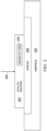
Figure 1 is an illustration of a block diagram of a manufacturing environment in which a catalyst solution is applied in accordance with an illustrative embodiment; -
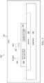
Figure 2 is an illustration of a block diagram of a catalyst solution applied to a substrate in accordance with an illustrative embodiment; -
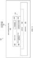
Figure 3 is an illustration of a block diagram of a catalyst solution on a surface of a substrate in an oven in accordance with an illustrative embodiment; -
Figure 4 is an illustration of a block diagram of a substrate in an electroless plating tank in accordance with an illustrative embodiment; -
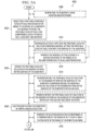
Figures 5A and5B are a flowchart of a method of directly writing a desired pattern of metal on a surface of a substrate in accordance with an illustrative embodiment; -
Figure 6 is a flowchart of a method of forming a catalyst solution in accordance with an illustrative embodiment; -
Figure 7 is an illustration of an aircraft manufacturing and service method in a form of a block diagram in accordance with an illustrative embodiment; and -
Figure 8 is an illustration of an aircraft in a form of a block diagram in which an illustrative embodiment may be implemented. - The illustrative examples recognize and take into account one or more different considerations. The illustrative examples recognize and take into account that current methods of forming circuitry utilize lithography and masking techniques that increase manufacturing time, cost, and waste. The illustrative examples also recognize and take into account that conventional direct writing techniques for conductive traces may not provide sufficient conductivity for some applications. The illustrative examples also recognize and take into account that conventional metal trace deposition techniques cannot enable desired technologies.
- The illustrative examples present a method of forming a desired pattern on a substrate with a metal trace. The illustrative examples present a catalyst solution for electroless plating, wherein the catalyst solution is printable and devoid of an amine. The illustrative examples present a method of directly writing a desired pattern of metal on a surface of a substrate.
- Turning now to
Figure 1 , an illustration of a block diagram of a manufacturing environment in which a catalyst solution is applied is depicted in accordance with an illustrative example.Manufacturing environment 100 includescatalyst solution 102 forelectroless plating 104.Catalyst solution 102 is printable 106 and devoid of an amine.Catalyst solution 102 is printable 106 based on material properties ofcatalyst solution 102. -
Catalyst solution 102 comprisescatalytic metal salt 108, solvent 110, andepoxy 112.Catalyst solution 102 is non-amine-based but reduces metal ions inelectroless plating 104.Catalytic metal salt 108 is solvent-soluble. In some illustrative examples,catalytic metal salt 108 comprises at least one of palladium, platinum, rhodium, iridium, osmium, ruthenium, copper, nickel, or silver. As used herein, the phrase "at least one of," when used with a list of items, means different combinations of one or more of the listed items may be used and only one of each item in the list may be needed. For example, "at least one of item A, item B, or item C" may include, without limitation, item A, item A and item B, or item B. This example also may include item A, item B, and item C or item B and item C. Of course, any combinations of these items may be present. In other examples, "at least one of" may be, for example, without limitation, two of item A; one of item B; and ten of item C; four of item B and seven of item C; or other suitable combinations. The item may be a particular object, thing, or a category. In other words, at least one of means any combination items and number of items may be used from the list but not all of the items in the list are required. - In some illustrative examples,
catalytic metal salt 108 comprises at least one of palladium or platinum. In some illustrative examples,catalytic metal salt 108 comprisespalladium acetate 114. In some illustrative examples,catalytic metal salt 108 is one of an acetate, a chloride, a sulfate, or a nitrate. - Characteristics of
catalytic metal salt 108 are selected to be printable 106.Diameters 115 of particles ofcatalytic metal salt 108 are selected to be printable 106 with a desired deposition method. In some illustrative examples,diameters 115 of particles ofcatalytic metal salt 108 are selected to promote formation of a metal layer inelectroless plating 104. In some illustrative examples,diameters 115 of particles ofcatalytic metal salt 108 are smaller than a desirednozzle 130diameter 132 of adirect write applicator 128. In some illustrative examples,catalytic metal salt 108 is selected based on a desired resistivity of the resulting metal pattern. - Solvent 110 is selected based on the selection of
epoxy 112 andcatalytic metal salt 108. Solvent 110 is selected to place the selectedepoxy 112 and the selectedcatalytic metal salt 108 into solution. In some illustrative examples, solvent 110 comprises at least one of methyl-ethyl-ketone 116,tetrahydrofuran 118, ortoluene 120. - In some illustrative examples,
catalyst solution 102 has a volume percentage of solvent 110 selected to provideviscosity 122 compatible with selecteddeposition equipment 126. In some illustrative examples,deposition equipment 126 may also be referred to asdirect write applicator 128. In some illustrative examples, direct write processes can be described as "printing" conductive traces using metallic ink. In some illustrative examples,deposition equipment 126 takes the form ofaerosol jet 124.Aerosol jet 124 includes atomization and deposition. Atomization foraerosol jet 124 is selected from ultrasonic or pneumatic atomization. A deposition head foraerosol jet 124 can be a macro deposition head, a micro deposition head, or a wide head. In some illustrative examples, a macro deposition head has nozzle/tip diameters in the range of 0.500 millimeters to 2.50 millimeters. In some illustrative examples, a macro deposition head has trace widths between 100 microns and 2000 microns. In some illustrative examples, a micro deposition head has nozzle/tip diameters in the range of 0.100 millimeters to 0.300 millimeters. In some illustrative examples, a micro deposition head has trace widths between 20 microns and 200 microns. In some illustrative examples, a wide head foraerosol jet 124 has a nozzle/tip width of 10 millimeters. In some illustrative examples, a trace thickness deposited byaerosol jet 124 is in the range of 2 micrometers to 3 micrometers per layer. - In some illustrative examples,
catalyst solution 102 has a volume percentage of solvent 110 selected to provideviscosity 122 compatible withaerosol jet 124. In some illustrative examples,viscosity 122 is between 25 centipoise and 125 centipoise to enable spray coating. - In some illustrative examples, to form
catalyst solution 102,catalytic metal salt 108 is dissolved in solvent 110 to form a first solution andepoxy 112 is mixed with solvent 110 separately to form a second solution. Afterwards, the first solution is added to the second solution to form a combination. In some illustrative examples, adding the first solution to the second solution formscatalyst solution 102. In some illustrative examples, additional solvent 110 is introduced to the combination to formcatalyst solution 102. In some illustrative examples, additional solvent 110 is introduced to the combination to achieve a desired value forviscosity 122. - In some illustrative examples, additional solvent 110 is introduced to the combination to achieve a desired mass ratio in
catalyst solution 102. - Once formed,
catalyst solution 102 is applied to surface 140 ofsubstrate 142 in desiredpattern 134 bydeposition equipment 126. In some illustrative examples,deposition equipment 126 appliescatalyst solution 102 atdeposition speed 133 in the range of 20 millimeters/second to 40 millimeters/second. - Desired
pattern 134 takes any desirable form for utilizing the conductivity ofcatalyst solution 102 and metal film formed byelectroless plating 104. In some illustrative examples, desiredpattern 134 takes the form of conductive wiring. In some illustrative examples, desiredpattern 134 takes the form ofcircuit 136. In some illustrative examples, desiredpattern 134 is decorative 138. Desiredpattern 134 is applied to surface 140 ofsubstrate 142 bydeposition equipment 126. -
Substrate 142 is a material in which conductivity of only portions ofsurface 140 is desirable.Substrate 142 takes any desirable form. By applyingcatalyst solution 102 and performingelectroless plating 104, the conductivity ofsubstrate 142 is manipulated. In some illustrative examples,substrate 142 comprisesnon-conductive material 144. In some illustrative examples,substrate 142 is formed of one ofpolymer 146 orcomposite 148. In some illustrative examples,substrate 142 takes the form ofpart 150.Part 150 is a component of a platform. The platform can take any desirable form. Although the illustrative examples for an illustrative embodiment below are described with respect to an aircraft, an illustrative embodiment may be applied to other types of platforms. The platform may be, for example, a mobile platform, a stationary platform, a land-based structure, an aquatic-based structure, and a space-based structure. More specifically, the platform, may be a surface ship, a tank, a personnel carrier, a train, a spacecraft, a space station, a satellite, a submarine, an automobile, a power plant, a bridge, a dam, a house, a manufacturing facility, a building, an electronic device such as a phone, computer, tablet, sensor, and other suitable platforms. For example, whensubstrate 142 takes the form ofpart 150,substrate 142 can be a panel, a circuit, a faceplate, or any other desirable type of part. In other illustrative examples,substrate 142 takes the form offilm 152. -
Substrate 142 is formed in any desirable manner such thatsurface 140 has a roughness that enables directly depositingcatalyst solution 102.Substrate 142 can be formed through molding, machining, oradditive manufacturing 154. In some illustrative examples, whensubstrate 142 is formed byadditive manufacturing 154,additive manufacturing equipment 156 is present inmanufacturing environment 100. - After deposition of
catalyst solution 102 to surface 140 ofsubstrate 142,catalyst solution 102 is dried. In some illustrative examples, by dryingcatalyst solution 102,epoxy 112 is dried and solvent 110 is driven off. In some illustrative examples,epoxy 112 is heat curable 158 andepoxy 112 is dried and partially cured by applying heat. In some embodiments,epoxy 112 comprises heat curable 158 such as E3710 or EC2290. In some illustrative examples,epoxy 112 is UV curable 160. - Drying is performed at a time and temperature to evaporate solvent 110 and
dry epoxy 112. By only partially curingepoxy 112, active sites of the catalyst are maintained. In some illustrative examples, the drying is performed at a temperature in the range of 75 degrees Celsius to 135 degrees Celsius. In some illustrative examples, the drying is performed for a time in the range of 5 minutes to 30 minutes. - After
catalyst solution 102 is dried onsubstrate 142,substrate 142 is placed intoelectroless plating tank 164.Electroless plating 104 inelectroless plating tank 164 does not utilize an electric current. Metal ions in metalaqueous solution 162 are reduced and deposited on the catalytically activated portions ofsurface 140. Metal ions in metalaqueous solution 162 are reduced and deposited onto the driedcatalyst solution 102 in desiredpattern 134. In some illustrative examples, metalaqueous solution 162 comprises at least one of nickel, cobalt, iron, or copper. In some illustrative examples, metalaqueous solution 162 comprises at least one of nickel, cobalt, iron, copper, gold, silver, palladium, platinum, rhodium, or ruthenium. - The thickness of the metal film deposited during
electroless plating 104 is controlled by modifying thetemperature 166 andtime 168 ofelectroless plating 104. The thickness of the metal film deposited duringelectroless plating 104 is affected by the type and amount ofcatalytic metal salt 108. - In one example of forming
catalyst solution 102, 0.25 grams ofpalladium acetate 114 is dissolved in 20 milliliters methyl-ethyl-ketone 116 and then mixed until dissolved in solution. Separately, 2 grams ofepoxy 112, such as EC3710 from 3M, and 60 grams oftoluene 120 are combined. Afterwards, thepalladium acetate 114 solution is added to the epoxy 112 solution. An additional amount of methyl-ethyl-ketone 116 can be added to achieve desired mass ratios. In one illustrative example, the resultingcatalyst solution 102 comprises 0.25 grams ofpalladium acetate 114, 2 grams ofepoxy ketone 116, and 60 grams oftoluene 120. - In another example of forming
catalyst solution 102, 0.25 grams ofpalladium acetate 114 is dissolved in 20 milliliters methyl-ethyl-ketone 116 and then mixed until dissolved in solution. Separately, 2 grams ofepoxy 112, such as EC3710 from 3M, and 40 grams oftetrahydrofuran 118 are combined. Afterwards, the palladium acetate solution is added to the epoxy solution. An additional amount of methyl-ethyl-ketone 116 can be added to achieve desired mass ratios. In one illustrative example, the resultingcatalyst solution 102 comprises 0.25 grams ofpalladium acetate 114, 2 grams ofepoxy 112, 159 grams of methyl-ethyl-ketone tetrahydrofuran 118. - Deposition of
catalyst solution 102, drying ofcatalyst solution 102, andelectroless plating 104 form acomponent comprising substrate 142 havingsurface 140, desiredpattern 134 of metal nanoparticles and epoxy onsurface 140 ofsubstrate 142, and a metal film formed over only desiredpattern 134 but not exposed portions ofsurface 140 ofsubstrate 142. Deposition ofcatalyst solution 102 andelectroless plating 104 can enable a variety of different technologies including embedded sensors, antennas, embedded lighting, electronic switches, wireless charging, decorative lighting, embedded heaters, and other technologies enabled by printed circuitry or printed metal wires. - The illustration of
catalyst solution 102,substrate 142, anddeposition equipment 126 inFigure 1 , is not meant to imply physical or architectural limitations to the manner in which an illustrative embodiment may be implemented. Other components in addition to or in place of the ones illustrated may be used. Some components may be unnecessary. Also, the blocks are presented to illustrate some functional components. One or more of these blocks may be combined, divided, or combined and divided into different blocks when implemented in an illustrative embodiment. For example,substrate 142 could have any desirable curvature. As another illustrative example, solvent 110 can take the form of another solvent other than methyl-ethyl-ketone 116,tetrahydrofuran 118, ortoluene 120. - Turning now to
Figure 2 , an illustration of a block diagram of a catalyst solution applied to a substrate is depicted in accordance with an illustrative embodiment.Substrate 200 is an implementation ofsubstrate 142 ofFigure 1 .Substrate 200 can be formed using any desirable manufacturing technique that results in a desirable surface roughness for directly writing onsurface 202.Substrate 200 can be formed using machining, molding, additive manufacturing, or any other desirable manufacturing method. -
Substrate 200 hassurface 202 upon whichcatalyst solution 204 is applied 206.Surface 202 is an implementation ofsurface 140 ofFigure 1 . Althoughsurface 202 appears planar due to the block diagram illustration,surface 202 can have any desirable curvature. In some illustrative examples,surface 202 comprises at least one of a curved surface or a complex surface.Surface 202 has any desirable surface roughness. -
Catalyst solution 204 is an implementation ofcatalyst solution 102 ofFigure 1 .Catalyst solution 204 is applied 206 using any desirable method. In some illustrative examples,catalyst solution 204 is deposited using a direct write applicator. In some illustrative examples,catalyst solution 204 is deposited using an aerosol jet. -
Catalyst solution 204 is applied to a portion ofsurface 202 in desiredpattern 208. Desiredpattern 208 can take any desirable form. In some illustrative examples, desiredpattern 208 takes the form of circuitry. In some illustrative examples, desiredpattern 208 is decorative. - Turning now to
Figure 3 , an illustration of a block diagram of a catalyst solution on a surface of a substrate in an oven is depicted in accordance with an illustrative embodiment. View 300 is a view ofsubstrate 200 ofFigure 2 inoven 301. View 300 is a view of dryingcatalyst solution 204 ofFigure 2 in desiredpattern 208 onsurface 202 ofsubstrate 200 withinoven 301. Inview 300,oven 301 appliesheat 302 tosubstrate 200 todry catalyst solution 204 applied 206 inFigure 2 . Dryingcatalyst solution 204 in desiredpattern 208 onsurface 202 ofsubstrate 200 drives off solvent 304 and dries the epoxy. Driving off solvent 304 forms catalytic metal salt andepoxy 306. The epoxy is dry in catalytic metal salt andepoxy 306. - Turning now to
Figure 4 , an illustration of a block diagram of a substrate in an electroless plating tank is depicted in accordance with an illustrative embodiment. View 400 is a view ofsubstrate 200 following drying inoven 301 ofFigure 3 . Inview 400substrate 200 is present inelectroless plating tank 401.Electroless plating tank 401 contains metalaqueous solution 402. Metalaqueous solution 402 interacts with catalytic metal salt andepoxy 306 ofFigure 3 to depositmetal film 404. - Electroless plating in
electroless plating tank 401 does not utilize an electric current. Metal ions in metalaqueous solution 402 are reduced and deposited on the catalytically activated portions ofsurface 202. Metal ions in metalaqueous solution 402 are reduced and deposited onto catalytic metal salt andepoxy 306 to formmetal film 404. As catalytic metal salt andepoxy 306 interacts with metalaqueous solution 402, catalytic metal salt and epoxy 306 forms metal nanoparticles andepoxy 406 onsurface 202. - Electroless plating in
electroless plating tank 401forms metal film 404 having auniform thickness 408.Thickness 408 is affected by the time of electroless plating. Increasing the time of electroless plating increasesthickness 408 ofmetal film 404. Increasingthickness 408 ofmetal film 404 reduces the resistivity of desiredpattern 208. - Depositing
metal film 404 using electrolessplating forms component 410.Component 410 comprisessubstrate 200 havingsurface 202, desiredpattern 208 of metal nanoparticles andepoxy 406 onsurface 202 ofsubstrate 200, andmetal film 404 formed over only desiredpattern 208 but not exposed portions ofsurface 202 ofsubstrate 200. - Turning now to
Figures 5A and5B , a flowchart of a method of directly writing a desired pattern of metal on a surface of a substrate is depicted in accordance with an illustrative embodiment. In some illustrative examples,method 500 can be performed to directly write desiredpattern 134 onsurface 140 ofsubstrate 142 ofFigure 1 . In some illustrative examples,method 500 can be used to applycatalyst solution 204 ofFigure 2 ,dry catalyst solution 204, andelectroless plate substrate 200 inFigure 4 . -
Method 500 directly writes a desired pattern of metal on a surface of a substrate.Method 500 selectively applies a printable catalyst solution devoid of an amine to a surface of a substrate in the desired pattern, the catalyst solution comprising a catalytic metal salt, a solvent, and an epoxy (operation 502). -
Method 500 dries the catalyst solution in the desired pattern on the surface of the substrate (operation 504).Method 500 electroless plates the substrate in a metal aqueous solution (operation 506). Afterwards,method 500 may terminate. - In some illustrative examples,
method 500 performsoperation 502,operation 504, and operation 506 without intervening processing to the substrate. In some illustrative examples,method 500 performsoperation 502,operation 504, and operation 506 without intervening neutralizing applied the substrate. - In some illustrative examples,
method 500 generates the substrate using additive manufacturing (operation 508). The additive manufacturing generates a surface with a surface roughness within a range for direct writing of catalyst solution. In some illustrative examples, selectively applying the catalyst solution comprises aerosol jetting the catalyst solution onto the surface of the substrate (operation 510). In some illustrative examples, the aerosol jetting is done at a deposition speed in the range of 20 millimeters/second to 40 millimeters/second (operation 512). - In some illustrative examples, the electroless plating is performed at a temperature in the range of 50 degrees Celsius to 80 degrees Celsius and a plating rate in the range of 150
- Å/minute to 325 Å/minute (operation 518). In some illustrative examples, the electroless plating is performed at a temperature in the range of 65 degrees Celsius to 75 degrees Celsius and at a plating rate of 250 Å/minute (operation 520). In some illustrative examples, the electroless plating is performed for a time in the range of 15 minutes to 3 hours (operation 522). In some illustrative examples, the electroless plating is performed for a time in the range of 15 minutes to 1 hour (operation 524).
- In some illustrative examples, drying the catalyst solution in the desired pattern on the surface of the substrate comprises drying the catalyst solution in the desired pattern on the surface of the substrate within an oven (operation 514). In some illustrative examples, drying the catalyst solution in the desired pattern on the surface of the substrate drives off the solvent and dries the epoxy (operation 516).
- In some illustrative examples, the metal aqueous solution comprises at least one of nickel, cobalt, iron, or copper (operation 526). In some illustrative examples, the metal aqueous solution comprises at least one of nickel, cobalt, iron, copper, gold, silver, palladium, platinum, rhodium, or ruthenium (operation 528).
- In some illustrative examples, the catalytic metal salt (108) comprises at least one of palladium, platinum, rhodium, iridium, osmium, ruthenium, copper, nickel, or silver (operation 530). In some illustrative examples, the catalytic metal salt comprises palladium acetate (operation 532).
- Turning now to
Figure 6 , a flowchart of a method of forming a catalyst solution is depicted in accordance with an illustrative embodiment. In some illustrative examples,method 600 is used to formcatalyst solution 102 ofFigure 1 . In some illustrative examples,method 600 is used to formcatalyst solution 204 ofFigure 2 . In some illustrative examples,method 600 is used to form a catalyst solution to be used inmethod 500 ofFigure 5 . -
Method 600 dissolves a catalytic metal salt in a first solvent to form a first solution (operation 602).Method 600 mixes an epoxy and a second solvent to form a second solution (operation 604).Method 600 adds the first solution to the second solution to form a combination (operation 606). Afterwards,method 600 may terminate. - In some illustrative examples, the first solvent is methyl-ethyl-ketone (operation 608). In some illustrative examples, the first solvent and the second solvent are the same (operation 610). In some illustrative examples, the second solvent is one of toluene or tetrahydrofuran (operation 612). In some illustrative examples, additional solvent is introduced to the combination to achieve a desired mass ration in a resulting catalyst solution (operation 614). In some illustrative examples, additional solvent is introduced to the combination to achieve a desired viscosity in a resulting catalyst solution (operation 616).
- The flowcharts and block diagrams in the different depicted examples illustrate the architecture, functionality, and operation of some possible implementations of apparatuses and methods in an illustrative example. In this regard, each block in the flowcharts or block diagrams may represent at least one of a module, a segment, a function, or a portion of an operation or step. As used herein, "a number of," when used with reference to items means one or more items.
- In some alternative implementations of an illustrative example, the function or functions noted in the blocks may occur out of the order noted in the figures. For example, in some cases, two blocks shown in succession may be executed substantially concurrently, or the blocks may sometimes be performed in the reverse order, depending upon the functionality involved. Also, other blocks may be added in addition to the illustrated blocks in a flowchart or block diagram. Some blocks may be optional. For example, any of
operation 508 throughoperation 532 may be optional. As another example, any ofoperation 608 throughoperation 616 may be optional. - Illustrative examples of the present disclosure may be described in the context of aircraft manufacturing and
service method 700 as shown inFigure 7 andaircraft 800 as shown inFigure 8 . Turning first toFigure 7 , an illustration of an aircraft manufacturing and service method in a form of a block diagram is depicted in accordance with an illustrative embodiment. During pre-production, aircraft manufacturing andservice method 700 may include specification anddesign 702 ofaircraft 800 inFigure 8 andmaterial procurement 704. - During production, component and
subassembly manufacturing 706 andsystem integration 708 ofaircraft 800 takes place. Thereafter,aircraft 800 may go through certification anddelivery 710 in order to be placed inservice 712. While inservice 712 by a customer,aircraft 800 is scheduled for routine maintenance andservice 714, which may include modification, reconfiguration, refurbishment, or other maintenance and service. - Each of the processes of aircraft manufacturing and
service method 700 may be performed or carried out by a system integrator, a third party, and/or an operator. In these examples, the operator may be a customer. For the purposes of this description, a system integrator may include, without limitation, any number of aircraft manufacturers and major-system subcontractors; a third party may include, without limitation, any number of vendors, subcontractors, and suppliers; and an operator may be an airline, a leasing company, a military entity, a service organization, and so on. - With reference now to
Figure 8 , an illustration of an aircraft in a form of a block diagram is depicted in which an illustrative embodiment may be implemented. In this example,aircraft 800 is produced by aircraft manufacturing andservice method 700 ofFigure 7 and may includeairframe 802 with plurality ofsystems 804 and interior 806. Examples ofsystems 804 include one or more ofpropulsion system 808,electrical system 810,hydraulic system 812, andenvironmental system 814. Any number of other systems may be included. - Apparatuses and methods embodied herein may be employed during at least one of the stages of aircraft manufacturing and
service method 700. One or more illustrative examples may be manufactured or used during at least one of component andsubassembly manufacturing 706, or maintenance andservice 714 ofFigure 7 . For example, components ofaircraft 800 may manufactured usingcatalyst solution 102 ofFigure 1 during component andsubassembly manufacturing 706. Replacement parts foraircraft 800 may be manufactured usingcatalyst solution 102 ofFigure 1 during maintenance andservice 714 ofFigure 7 . As another example,method 500 can be used to manufacture components of at least one ofinterior 806 orelectrical system 810.Method 600 can be used to form a catalyst solution for manufacturing a component of at least one ofinterior 806 orelectrical system 810. - The inclusion of an amine causes a catalyst solution to be incompatible with aerosol jetting. Accordingly, the catalyst solutions described herein do not include amines. Epoxy is included in the catalyst solution to enable the catalytic metal salt to be sprayed via aerosol spraying into desired patterns and then dried to adhere to the surface for electroless plating.
- The illustrative examples provide a catalyst solution, such as Palladium catalyst, to seed the surface of a substrate. The illustrative examples then follow with electroless plating to provide for greater concentrations of conductive materials deposited to meet a designed conductivity.
- The illustrative examples do not require additional steps between the applying the catalyst solution, drying the catalyst solution, and the electroless plating. The illustrative examples also do not require sensitizing or neutralizing steps prior to or between the applying the catalyst solution, drying the catalyst solution, and the electroless plating.
- The description of the different illustrative embodiments has been presented for purposes of illustration and description, and is not intended to be exhaustive or limited to the embodiments in the form disclosed. Many modifications and variations will be apparent to those of ordinary skill in the art. Further, different illustrative embodiments may provide different features as compared to other illustrative embodiments. The embodiment or embodiments selected are chosen and described in order to best explain the principles of the embodiments, the practical application, and to enable others of ordinary skill in the art to understand the disclosure for various embodiments with various modifications as are suited to the particular use contemplated.
Claims (15)
- A catalyst solution (102) for electroless plating, wherein the catalyst solution is printable and devoid of an amine, the catalyst solution comprising:a catalytic metal salt (108);a solvent (110); andan epoxy (112).
- The catalyst solution of claim 1, wherein the catalytic metal salt (108) comprises at least one of palladium, platinum, rhodium, iridium, osmium, ruthenium, copper, nickel, or silver.
- The catalyst solution of claim 1 or 2, wherein the solvent (110) comprises at least one of methyl-ethyl-ketone, tetrahydrofuran, or toluene.
- The catalyst solution of any of the preceding claims, wherein the catalyst solution (102) has a viscosity (122) in a range of 25 centipoise to 125 centipoise.
- The catalyst solution of any of the preceding claims wherein the catalytic metal salt (108) comprises one of an acetate, a chloride, a sulfate, or a nitrate.
- The catalyst solution of any of the preceding claims, wherein the catalytic metal salt (108) comprises palladium acetate.
- A method of directly writing a desired pattern of metal on a surface of a substrate, the method comprising:selectively applying a printable catalyst solution devoid of an amine to a surface of a substrate in the desired pattern the catalyst solution comprising a catalytic metal salt, a solvent, and an epoxy,drying the catalyst solution in the desired pattern on the surface of the substrate; andelectroless plating the substrate in a metal aqueous solution.
- The method of claim 7, wherein selectively applying the catalyst solution comprises aerosol jetting the catalyst solution onto the surface of the substrate, at a deposition speed in a range of 20 millimeter/second to 40 millimeter/second.
- The method of claim 7 or 8, wherein the electroless plating is performed at a temperature in a range of 50 degrees Celsius to 80 degrees Celsius and a plating rate in a range of 150 Å/minute to 325 Å/minute.
- The method of any of the claims 7 to 9, wherein the electroless plating is performed at a temperature in a range of 65 degrees Celsius to 75 degrees Celsius and at a plating rate of 250 Å/minute.
- The method of any of the claims 7 to 10, wherein the electroless plating is performed for a time in a range of 15 minutes to 3 hours.
- The method of any of the claims 7 to 11, wherein the electroless plating is performed for a time in a range of 15 minutes to 1 hour.
- The method of any of the claims 7 to 12, wherein the catalytic metal salt comprises at least one of palladium, platinum, rhodium, iridium, osmium, ruthenium, copper, nickel, or silver preferably wherein the catalytic metal salt comprises palladium acetate
- A component comprising:a substrate having a surfacea desired pattern of metal nanoparticles and epoxy on the surface of the substrate anda metal film formed over only the desired pattern but not exposed portions of the surface of the substrate, wherein the metal nanoparticles preferably comprise at least one of palladium, platinum, rhodium, iridium, osmium, ruthenium, copper, nickel, or silver, more preferably wherein the metal nanoparticles comprise palladium.
- Use of a catalyst solution according to any of the claims 1-6, in a method of any of the claims 7-13, for providing a component according to claim 14.
Applications Claiming Priority (1)
| Application Number | Priority Date | Filing Date | Title |
|---|---|---|---|
| US17/654,923 US12460301B2 (en) | 2022-03-15 | 2022-03-15 | Catalyst solution for electroless plating devoid of an amine |
Publications (2)
| Publication Number | Publication Date |
|---|---|
| EP4245885A2 true EP4245885A2 (en) | 2023-09-20 |
| EP4245885A3 EP4245885A3 (en) | 2023-11-15 |
Family
ID=85285045
Family Applications (1)
| Application Number | Title | Priority Date | Filing Date |
|---|---|---|---|
| EP23157540.8A Pending EP4245885A3 (en) | 2022-03-15 | 2023-02-20 | Catalyst solution for electroless plating devoid of an amine |
Country Status (5)
| Country | Link |
|---|---|
| US (1) | US12460301B2 (en) |
| EP (1) | EP4245885A3 (en) |
| JP (1) | JP2023135643A (en) |
| KR (1) | KR20230134988A (en) |
| CN (1) | CN116770277A (en) |
Family Cites Families (10)
| Publication number | Priority date | Publication date | Assignee | Title |
|---|---|---|---|---|
| US3423226A (en) | 1965-06-28 | 1969-01-21 | Mc Donnell Douglas Corp | Plating of non-metallic bodies |
| US3437507A (en) | 1965-07-16 | 1969-04-08 | Mc Donnell Douglas Corp | Plating of substrates |
| US5053280A (en) * | 1988-09-20 | 1991-10-01 | Hitachi-Chemical Co., Ltd. | Adhesive composition for printed wiring boards with acrylonitrile-butadiene rubber having carboxyl groups and 20 ppm or less metal ionic impurities; an alkyl phenol resin; an epoxy resin; palladium catalyst, and coupling agent |
| US6344242B1 (en) | 1999-09-10 | 2002-02-05 | Mcdonnell Douglas Corporation | Sol-gel catalyst for electroless plating |
| KR100529371B1 (en) * | 2003-07-29 | 2005-11-21 | 주식회사 엘지화학 | Catalyst precursor resin composition and preparation method of light-penetrating electro-magnetic interference shielding material using the same |
| US8404097B2 (en) | 2004-02-04 | 2013-03-26 | The Boeing Company | Process for plating a metal object with a wear-resistant coating and method of coating |
| JP4914012B2 (en) | 2005-02-14 | 2012-04-11 | キヤノン株式会社 | Manufacturing method of structure |
| TWI524939B (en) | 2011-08-17 | 2016-03-11 | 羅門哈斯電子材料有限公司 | Stabilizer for electroless metallization |
| US9217093B1 (en) * | 2014-05-30 | 2015-12-22 | Xerox Corporation | Palladium ink compositions |
| US10787743B2 (en) | 2017-08-28 | 2020-09-29 | The Boeing Company | Depositing a structurally hard, wear resistant metal coating onto a substrate |
-
2022
- 2022-03-15 US US17/654,923 patent/US12460301B2/en active Active
-
2023
- 2023-02-20 EP EP23157540.8A patent/EP4245885A3/en active Pending
- 2023-03-10 KR KR1020230031786A patent/KR20230134988A/en active Pending
- 2023-03-14 CN CN202310239411.5A patent/CN116770277A/en active Pending
- 2023-03-14 JP JP2023039217A patent/JP2023135643A/en active Pending
Also Published As
| Publication number | Publication date |
|---|---|
| CN116770277A (en) | 2023-09-19 |
| US12460301B2 (en) | 2025-11-04 |
| US20230295808A1 (en) | 2023-09-21 |
| JP2023135643A (en) | 2023-09-28 |
| EP4245885A3 (en) | 2023-11-15 |
| KR20230134988A (en) | 2023-09-22 |
Similar Documents
| Publication | Publication Date | Title |
|---|---|---|
| JP6400133B2 (en) | Method and system for distributed network of piezoelectric sensors with nano-particle ink for structural health monitoring | |
| CN1946880B (en) | Selective catalytic activation of non-conductive substrates | |
| US20060134318A1 (en) | Method of forming a conductive metal region on a substrate | |
| US20110023297A1 (en) | Multi-layered printed circuit board and method for fabricating the same | |
| EP2292421A1 (en) | Layered product having porous layer and functional layered product made with the same | |
| GB2382798A (en) | Inkjet printer which deposits at least two fluids on a substrate such that the fluids react chemically to form a product thereon | |
| JP2001516805A (en) | Adhesion of substances on surfaces | |
| JP6845146B2 (en) | Methods and equipment for manufacturing metal patterns for decoration and / or function on a substrate, production methods for goods including the manufacturing methods, and consumables used. | |
| WO2003091788A2 (en) | Process for forming a patterned thin film conductive structure on a substrate | |
| CN105723817A (en) | Flexible printed circuit board and method for manufacturing same | |
| King et al. | Aerosol jet® direct write printing for mil-aero electronic applications | |
| TW201511974A (en) | Inkjet method of forming metal pattern and molded interconnect device therefrom | |
| US20050130397A1 (en) | Formation of layers on substrates | |
| Wu et al. | Fabrication of polyetheretherketone (PEEK)-based 3D electronics with fine resolution by a hydrophobic treatment assisted hybrid additive manufacturing method | |
| CN109299624A (en) | A kind of preparation method of RFID antenna | |
| EP4245885A2 (en) | Catalyst solution for electroless plating devoid of an amine | |
| KR100765363B1 (en) | Manufacturing method of electroconductive particle | |
| WO2005087979A2 (en) | A method and a device for deposition of a metal layer on a non-conducting surface of a substrate | |
| GB2381274A (en) | High resolution patterning method | |
| JP2006150353A (en) | UV curable catalyst composition | |
| US20040078968A1 (en) | Printed circuit board manufacturing method | |
| EP1687461A2 (en) | The formation of layers on substrates | |
| CN100521879C (en) | Method for making layers and wiring board made thereby | |
| US6703186B1 (en) | Method of forming a conductive pattern on a circuit board | |
| CN115320269B (en) | Method for high-precision ink-jet printing antenna |
Legal Events
| Date | Code | Title | Description |
|---|---|---|---|
| PUAI | Public reference made under article 153(3) epc to a published international application that has entered the european phase |
Free format text: ORIGINAL CODE: 0009012 |
|
| STAA | Information on the status of an ep patent application or granted ep patent |
Free format text: STATUS: THE APPLICATION HAS BEEN PUBLISHED |
|
| AK | Designated contracting states |
Kind code of ref document: A2 Designated state(s): AL AT BE BG CH CY CZ DE DK EE ES FI FR GB GR HR HU IE IS IT LI LT LU LV MC ME MK MT NL NO PL PT RO RS SE SI SK SM TR |
|
| PUAL | Search report despatched |
Free format text: ORIGINAL CODE: 0009013 |
|
| AK | Designated contracting states |
Kind code of ref document: A3 Designated state(s): AL AT BE BG CH CY CZ DE DK EE ES FI FR GB GR HR HU IE IS IT LI LT LU LV MC ME MK MT NL NO PL PT RO RS SE SI SK SM TR |
|
| RIC1 | Information provided on ipc code assigned before grant |
Ipc: C23C 18/31 20060101ALI20231010BHEP Ipc: C23C 18/16 20060101AFI20231010BHEP |
|
| STAA | Information on the status of an ep patent application or granted ep patent |
Free format text: STATUS: REQUEST FOR EXAMINATION WAS MADE |
|
| 17P | Request for examination filed |
Effective date: 20240511 |
|
| RBV | Designated contracting states (corrected) |
Designated state(s): AL AT BE BG CH CY CZ DE DK EE ES FI FR GB GR HR HU IE IS IT LI LT LU LV MC ME MK MT NL NO PL PT RO RS SE SI SK SM TR |