EP4245659A2 - Verbundträgerverbindung mit keilförmigen inneren und äusseren verriegelungsmerkmalen - Google Patents
Verbundträgerverbindung mit keilförmigen inneren und äusseren verriegelungsmerkmalen Download PDFInfo
- Publication number
- EP4245659A2 EP4245659A2 EP23191200.7A EP23191200A EP4245659A2 EP 4245659 A2 EP4245659 A2 EP 4245659A2 EP 23191200 A EP23191200 A EP 23191200A EP 4245659 A2 EP4245659 A2 EP 4245659A2
- Authority
- EP
- European Patent Office
- Prior art keywords
- end piece
- wedge
- composite tube
- composite
- shaped
- Prior art date
- Legal status (The legal status is an assumption and is not a legal conclusion. Google has not performed a legal analysis and makes no representation as to the accuracy of the status listed.)
- Pending
Links
Images


Classifications
-
- B—PERFORMING OPERATIONS; TRANSPORTING
- B29—WORKING OF PLASTICS; WORKING OF SUBSTANCES IN A PLASTIC STATE IN GENERAL
- B29D—PRODUCING PARTICULAR ARTICLES FROM PLASTICS OR FROM SUBSTANCES IN A PLASTIC STATE
- B29D99/00—Subject matter not provided for in other groups of this subclass
- B29D99/0046—Producing rods
-
- F—MECHANICAL ENGINEERING; LIGHTING; HEATING; WEAPONS; BLASTING
- F16—ENGINEERING ELEMENTS AND UNITS; GENERAL MEASURES FOR PRODUCING AND MAINTAINING EFFECTIVE FUNCTIONING OF MACHINES OR INSTALLATIONS; THERMAL INSULATION IN GENERAL
- F16B—DEVICES FOR FASTENING OR SECURING CONSTRUCTIONAL ELEMENTS OR MACHINE PARTS TOGETHER, e.g. NAILS, BOLTS, CIRCLIPS, CLAMPS, CLIPS OR WEDGES; JOINTS OR JOINTING
- F16B7/00—Connections of rods or tubes, e.g. of non-circular section, mutually, including resilient connections
- F16B7/04—Clamping or clipping connections
- F16B7/0406—Clamping or clipping connections for rods or tubes being coaxial
- F16B7/0413—Clamping or clipping connections for rods or tubes being coaxial for tubes using the innerside thereof
- F16B7/042—Clamping or clipping connections for rods or tubes being coaxial for tubes using the innerside thereof with a locking element, e.g. pin, ball or pushbutton, engaging in a hole in the wall of at least one tube
-
- B—PERFORMING OPERATIONS; TRANSPORTING
- B29—WORKING OF PLASTICS; WORKING OF SUBSTANCES IN A PLASTIC STATE IN GENERAL
- B29C—SHAPING OR JOINING OF PLASTICS; SHAPING OF MATERIAL IN A PLASTIC STATE, NOT OTHERWISE PROVIDED FOR; AFTER-TREATMENT OF THE SHAPED PRODUCTS, e.g. REPAIRING
- B29C65/00—Joining or sealing of preformed parts, e.g. welding of plastics materials; Apparatus therefor
- B29C65/56—Joining or sealing of preformed parts, e.g. welding of plastics materials; Apparatus therefor using mechanical means or mechanical connections, e.g. form-fits
- B29C65/64—Joining a non-plastics element to a plastics element, e.g. by force
-
- B—PERFORMING OPERATIONS; TRANSPORTING
- B29—WORKING OF PLASTICS; WORKING OF SUBSTANCES IN A PLASTIC STATE IN GENERAL
- B29C—SHAPING OR JOINING OF PLASTICS; SHAPING OF MATERIAL IN A PLASTIC STATE, NOT OTHERWISE PROVIDED FOR; AFTER-TREATMENT OF THE SHAPED PRODUCTS, e.g. REPAIRING
- B29C66/00—General aspects of processes or apparatus for joining preformed parts
- B29C66/01—General aspects dealing with the joint area or with the area to be joined
- B29C66/05—Particular design of joint configurations
- B29C66/10—Particular design of joint configurations particular design of the joint cross-sections
- B29C66/11—Joint cross-sections comprising a single joint-segment, i.e. one of the parts to be joined comprising a single joint-segment in the joint cross-section
- B29C66/112—Single lapped joints
- B29C66/1122—Single lap to lap joints, i.e. overlap joints
-
- B—PERFORMING OPERATIONS; TRANSPORTING
- B29—WORKING OF PLASTICS; WORKING OF SUBSTANCES IN A PLASTIC STATE IN GENERAL
- B29C—SHAPING OR JOINING OF PLASTICS; SHAPING OF MATERIAL IN A PLASTIC STATE, NOT OTHERWISE PROVIDED FOR; AFTER-TREATMENT OF THE SHAPED PRODUCTS, e.g. REPAIRING
- B29C66/00—General aspects of processes or apparatus for joining preformed parts
- B29C66/01—General aspects dealing with the joint area or with the area to be joined
- B29C66/05—Particular design of joint configurations
- B29C66/20—Particular design of joint configurations particular design of the joint lines, e.g. of the weld lines
- B29C66/22—Particular design of joint configurations particular design of the joint lines, e.g. of the weld lines said joint lines being in the form of recurring patterns
- B29C66/227—Particular design of joint configurations particular design of the joint lines, e.g. of the weld lines said joint lines being in the form of recurring patterns being in the form of repetitive interlocking undercuts, e.g. in the form of puzzle cuts
- B29C66/2274—Dovetailed interlocking undercuts
-
- B—PERFORMING OPERATIONS; TRANSPORTING
- B29—WORKING OF PLASTICS; WORKING OF SUBSTANCES IN A PLASTIC STATE IN GENERAL
- B29C—SHAPING OR JOINING OF PLASTICS; SHAPING OF MATERIAL IN A PLASTIC STATE, NOT OTHERWISE PROVIDED FOR; AFTER-TREATMENT OF THE SHAPED PRODUCTS, e.g. REPAIRING
- B29C66/00—General aspects of processes or apparatus for joining preformed parts
- B29C66/50—General aspects of joining tubular articles; General aspects of joining long products, i.e. bars or profiled elements; General aspects of joining single elements to tubular articles, hollow articles or bars; General aspects of joining several hollow-preforms to form hollow or tubular articles
- B29C66/51—Joining tubular articles, profiled elements or bars; Joining single elements to tubular articles, hollow articles or bars; Joining several hollow-preforms to form hollow or tubular articles
- B29C66/52—Joining tubular articles, bars or profiled elements
- B29C66/524—Joining profiled elements
-
- B—PERFORMING OPERATIONS; TRANSPORTING
- B29—WORKING OF PLASTICS; WORKING OF SUBSTANCES IN A PLASTIC STATE IN GENERAL
- B29C—SHAPING OR JOINING OF PLASTICS; SHAPING OF MATERIAL IN A PLASTIC STATE, NOT OTHERWISE PROVIDED FOR; AFTER-TREATMENT OF THE SHAPED PRODUCTS, e.g. REPAIRING
- B29C66/00—General aspects of processes or apparatus for joining preformed parts
- B29C66/50—General aspects of joining tubular articles; General aspects of joining long products, i.e. bars or profiled elements; General aspects of joining single elements to tubular articles, hollow articles or bars; General aspects of joining several hollow-preforms to form hollow or tubular articles
- B29C66/51—Joining tubular articles, profiled elements or bars; Joining single elements to tubular articles, hollow articles or bars; Joining several hollow-preforms to form hollow or tubular articles
- B29C66/53—Joining single elements to tubular articles, hollow articles or bars
- B29C66/534—Joining single elements to open ends of tubular or hollow articles or to the ends of bars
-
- B—PERFORMING OPERATIONS; TRANSPORTING
- B29—WORKING OF PLASTICS; WORKING OF SUBSTANCES IN A PLASTIC STATE IN GENERAL
- B29C—SHAPING OR JOINING OF PLASTICS; SHAPING OF MATERIAL IN A PLASTIC STATE, NOT OTHERWISE PROVIDED FOR; AFTER-TREATMENT OF THE SHAPED PRODUCTS, e.g. REPAIRING
- B29C66/00—General aspects of processes or apparatus for joining preformed parts
- B29C66/50—General aspects of joining tubular articles; General aspects of joining long products, i.e. bars or profiled elements; General aspects of joining single elements to tubular articles, hollow articles or bars; General aspects of joining several hollow-preforms to form hollow or tubular articles
- B29C66/63—Internally supporting the article during joining
-
- B—PERFORMING OPERATIONS; TRANSPORTING
- B29—WORKING OF PLASTICS; WORKING OF SUBSTANCES IN A PLASTIC STATE IN GENERAL
- B29C—SHAPING OR JOINING OF PLASTICS; SHAPING OF MATERIAL IN A PLASTIC STATE, NOT OTHERWISE PROVIDED FOR; AFTER-TREATMENT OF THE SHAPED PRODUCTS, e.g. REPAIRING
- B29C66/00—General aspects of processes or apparatus for joining preformed parts
- B29C66/70—General aspects of processes or apparatus for joining preformed parts characterised by the composition, physical properties or the structure of the material of the parts to be joined; Joining with non-plastics material
- B29C66/72—General aspects of processes or apparatus for joining preformed parts characterised by the composition, physical properties or the structure of the material of the parts to be joined; Joining with non-plastics material characterised by the structure of the material of the parts to be joined
- B29C66/721—Fibre-reinforced materials
-
- B—PERFORMING OPERATIONS; TRANSPORTING
- B29—WORKING OF PLASTICS; WORKING OF SUBSTANCES IN A PLASTIC STATE IN GENERAL
- B29C—SHAPING OR JOINING OF PLASTICS; SHAPING OF MATERIAL IN A PLASTIC STATE, NOT OTHERWISE PROVIDED FOR; AFTER-TREATMENT OF THE SHAPED PRODUCTS, e.g. REPAIRING
- B29C66/00—General aspects of processes or apparatus for joining preformed parts
- B29C66/70—General aspects of processes or apparatus for joining preformed parts characterised by the composition, physical properties or the structure of the material of the parts to be joined; Joining with non-plastics material
- B29C66/73—General aspects of processes or apparatus for joining preformed parts characterised by the composition, physical properties or the structure of the material of the parts to be joined; Joining with non-plastics material characterised by the intensive physical properties of the material of the parts to be joined, by the optical properties of the material of the parts to be joined, by the extensive physical properties of the parts to be joined, by the state of the material of the parts to be joined or by the material of the parts to be joined being a thermoplastic or a thermoset
- B29C66/737—General aspects of processes or apparatus for joining preformed parts characterised by the composition, physical properties or the structure of the material of the parts to be joined; Joining with non-plastics material characterised by the intensive physical properties of the material of the parts to be joined, by the optical properties of the material of the parts to be joined, by the extensive physical properties of the parts to be joined, by the state of the material of the parts to be joined or by the material of the parts to be joined being a thermoplastic or a thermoset characterised by the state of the material of the parts to be joined
- B29C66/7375—General aspects of processes or apparatus for joining preformed parts characterised by the composition, physical properties or the structure of the material of the parts to be joined; Joining with non-plastics material characterised by the intensive physical properties of the material of the parts to be joined, by the optical properties of the material of the parts to be joined, by the extensive physical properties of the parts to be joined, by the state of the material of the parts to be joined or by the material of the parts to be joined being a thermoplastic or a thermoset characterised by the state of the material of the parts to be joined uncured, partially cured or fully cured
- B29C66/73751—General aspects of processes or apparatus for joining preformed parts characterised by the composition, physical properties or the structure of the material of the parts to be joined; Joining with non-plastics material characterised by the intensive physical properties of the material of the parts to be joined, by the optical properties of the material of the parts to be joined, by the extensive physical properties of the parts to be joined, by the state of the material of the parts to be joined or by the material of the parts to be joined being a thermoplastic or a thermoset characterised by the state of the material of the parts to be joined uncured, partially cured or fully cured the to-be-joined area of at least one of the parts to be joined being uncured, i.e. non cross-linked, non vulcanized
-
- B—PERFORMING OPERATIONS; TRANSPORTING
- B29—WORKING OF PLASTICS; WORKING OF SUBSTANCES IN A PLASTIC STATE IN GENERAL
- B29C—SHAPING OR JOINING OF PLASTICS; SHAPING OF MATERIAL IN A PLASTIC STATE, NOT OTHERWISE PROVIDED FOR; AFTER-TREATMENT OF THE SHAPED PRODUCTS, e.g. REPAIRING
- B29C66/00—General aspects of processes or apparatus for joining preformed parts
- B29C66/70—General aspects of processes or apparatus for joining preformed parts characterised by the composition, physical properties or the structure of the material of the parts to be joined; Joining with non-plastics material
- B29C66/73—General aspects of processes or apparatus for joining preformed parts characterised by the composition, physical properties or the structure of the material of the parts to be joined; Joining with non-plastics material characterised by the intensive physical properties of the material of the parts to be joined, by the optical properties of the material of the parts to be joined, by the extensive physical properties of the parts to be joined, by the state of the material of the parts to be joined or by the material of the parts to be joined being a thermoplastic or a thermoset
- B29C66/739—General aspects of processes or apparatus for joining preformed parts characterised by the composition, physical properties or the structure of the material of the parts to be joined; Joining with non-plastics material characterised by the intensive physical properties of the material of the parts to be joined, by the optical properties of the material of the parts to be joined, by the extensive physical properties of the parts to be joined, by the state of the material of the parts to be joined or by the material of the parts to be joined being a thermoplastic or a thermoset characterised by the material of the parts to be joined being a thermoplastic or a thermoset
- B29C66/7392—General aspects of processes or apparatus for joining preformed parts characterised by the composition, physical properties or the structure of the material of the parts to be joined; Joining with non-plastics material characterised by the intensive physical properties of the material of the parts to be joined, by the optical properties of the material of the parts to be joined, by the extensive physical properties of the parts to be joined, by the state of the material of the parts to be joined or by the material of the parts to be joined being a thermoplastic or a thermoset characterised by the material of the parts to be joined being a thermoplastic or a thermoset characterised by the material of at least one of the parts being a thermoplastic
-
- B—PERFORMING OPERATIONS; TRANSPORTING
- B29—WORKING OF PLASTICS; WORKING OF SUBSTANCES IN A PLASTIC STATE IN GENERAL
- B29C—SHAPING OR JOINING OF PLASTICS; SHAPING OF MATERIAL IN A PLASTIC STATE, NOT OTHERWISE PROVIDED FOR; AFTER-TREATMENT OF THE SHAPED PRODUCTS, e.g. REPAIRING
- B29C66/00—General aspects of processes or apparatus for joining preformed parts
- B29C66/70—General aspects of processes or apparatus for joining preformed parts characterised by the composition, physical properties or the structure of the material of the parts to be joined; Joining with non-plastics material
- B29C66/73—General aspects of processes or apparatus for joining preformed parts characterised by the composition, physical properties or the structure of the material of the parts to be joined; Joining with non-plastics material characterised by the intensive physical properties of the material of the parts to be joined, by the optical properties of the material of the parts to be joined, by the extensive physical properties of the parts to be joined, by the state of the material of the parts to be joined or by the material of the parts to be joined being a thermoplastic or a thermoset
- B29C66/739—General aspects of processes or apparatus for joining preformed parts characterised by the composition, physical properties or the structure of the material of the parts to be joined; Joining with non-plastics material characterised by the intensive physical properties of the material of the parts to be joined, by the optical properties of the material of the parts to be joined, by the extensive physical properties of the parts to be joined, by the state of the material of the parts to be joined or by the material of the parts to be joined being a thermoplastic or a thermoset characterised by the material of the parts to be joined being a thermoplastic or a thermoset
- B29C66/7394—General aspects of processes or apparatus for joining preformed parts characterised by the composition, physical properties or the structure of the material of the parts to be joined; Joining with non-plastics material characterised by the intensive physical properties of the material of the parts to be joined, by the optical properties of the material of the parts to be joined, by the extensive physical properties of the parts to be joined, by the state of the material of the parts to be joined or by the material of the parts to be joined being a thermoplastic or a thermoset characterised by the material of the parts to be joined being a thermoplastic or a thermoset characterised by the material of at least one of the parts being a thermoset
-
- B—PERFORMING OPERATIONS; TRANSPORTING
- B29—WORKING OF PLASTICS; WORKING OF SUBSTANCES IN A PLASTIC STATE IN GENERAL
- B29C—SHAPING OR JOINING OF PLASTICS; SHAPING OF MATERIAL IN A PLASTIC STATE, NOT OTHERWISE PROVIDED FOR; AFTER-TREATMENT OF THE SHAPED PRODUCTS, e.g. REPAIRING
- B29C66/00—General aspects of processes or apparatus for joining preformed parts
- B29C66/70—General aspects of processes or apparatus for joining preformed parts characterised by the composition, physical properties or the structure of the material of the parts to be joined; Joining with non-plastics material
- B29C66/74—Joining plastics material to non-plastics material
- B29C66/742—Joining plastics material to non-plastics material to metals or their alloys
-
- B—PERFORMING OPERATIONS; TRANSPORTING
- B29—WORKING OF PLASTICS; WORKING OF SUBSTANCES IN A PLASTIC STATE IN GENERAL
- B29C—SHAPING OR JOINING OF PLASTICS; SHAPING OF MATERIAL IN A PLASTIC STATE, NOT OTHERWISE PROVIDED FOR; AFTER-TREATMENT OF THE SHAPED PRODUCTS, e.g. REPAIRING
- B29C70/00—Shaping composites, i.e. plastics material comprising reinforcements, fillers or preformed parts, e.g. inserts
- B29C70/68—Shaping composites, i.e. plastics material comprising reinforcements, fillers or preformed parts, e.g. inserts by incorporating or moulding on preformed parts, e.g. inserts or layers, e.g. foam blocks
- B29C70/86—Incorporated in coherent impregnated reinforcing layers, e.g. by winding
-
- F—MECHANICAL ENGINEERING; LIGHTING; HEATING; WEAPONS; BLASTING
- F16—ENGINEERING ELEMENTS AND UNITS; GENERAL MEASURES FOR PRODUCING AND MAINTAINING EFFECTIVE FUNCTIONING OF MACHINES OR INSTALLATIONS; THERMAL INSULATION IN GENERAL
- F16B—DEVICES FOR FASTENING OR SECURING CONSTRUCTIONAL ELEMENTS OR MACHINE PARTS TOGETHER, e.g. NAILS, BOLTS, CIRCLIPS, CLAMPS, CLIPS OR WEDGES; JOINTS OR JOINTING
- F16B7/00—Connections of rods or tubes, e.g. of non-circular section, mutually, including resilient connections
- F16B7/04—Clamping or clipping connections
- F16B7/0406—Clamping or clipping connections for rods or tubes being coaxial
- F16B7/0413—Clamping or clipping connections for rods or tubes being coaxial for tubes using the innerside thereof
-
- F—MECHANICAL ENGINEERING; LIGHTING; HEATING; WEAPONS; BLASTING
- F16—ENGINEERING ELEMENTS AND UNITS; GENERAL MEASURES FOR PRODUCING AND MAINTAINING EFFECTIVE FUNCTIONING OF MACHINES OR INSTALLATIONS; THERMAL INSULATION IN GENERAL
- F16C—SHAFTS; FLEXIBLE SHAFTS; ELEMENTS OR CRANKSHAFT MECHANISMS; ROTARY BODIES OTHER THAN GEARING ELEMENTS; BEARINGS
- F16C7/00—Connecting-rods or like links pivoted at both ends; Construction of connecting-rod heads
- F16C7/02—Constructions of connecting-rods with constant length
- F16C7/026—Constructions of connecting-rods with constant length made of fibre reinforced resin
-
- B—PERFORMING OPERATIONS; TRANSPORTING
- B29—WORKING OF PLASTICS; WORKING OF SUBSTANCES IN A PLASTIC STATE IN GENERAL
- B29C—SHAPING OR JOINING OF PLASTICS; SHAPING OF MATERIAL IN A PLASTIC STATE, NOT OTHERWISE PROVIDED FOR; AFTER-TREATMENT OF THE SHAPED PRODUCTS, e.g. REPAIRING
- B29C65/00—Joining or sealing of preformed parts, e.g. welding of plastics materials; Apparatus therefor
- B29C65/56—Joining or sealing of preformed parts, e.g. welding of plastics materials; Apparatus therefor using mechanical means or mechanical connections, e.g. form-fits
- B29C65/562—Joining or sealing of preformed parts, e.g. welding of plastics materials; Apparatus therefor using mechanical means or mechanical connections, e.g. form-fits using extra joining elements, i.e. which are not integral with the parts to be joined
-
- B—PERFORMING OPERATIONS; TRANSPORTING
- B29—WORKING OF PLASTICS; WORKING OF SUBSTANCES IN A PLASTIC STATE IN GENERAL
- B29C—SHAPING OR JOINING OF PLASTICS; SHAPING OF MATERIAL IN A PLASTIC STATE, NOT OTHERWISE PROVIDED FOR; AFTER-TREATMENT OF THE SHAPED PRODUCTS, e.g. REPAIRING
- B29C66/00—General aspects of processes or apparatus for joining preformed parts
- B29C66/01—General aspects dealing with the joint area or with the area to be joined
- B29C66/05—Particular design of joint configurations
- B29C66/10—Particular design of joint configurations particular design of the joint cross-sections
- B29C66/12—Joint cross-sections combining only two joint-segments; Tongue and groove joints; Tenon and mortise joints; Stepped joint cross-sections
- B29C66/124—Tongue and groove joints
- B29C66/1244—Tongue and groove joints characterised by the male part, i.e. the part comprising the tongue
- B29C66/12441—Tongue and groove joints characterised by the male part, i.e. the part comprising the tongue being a single wall
-
- B—PERFORMING OPERATIONS; TRANSPORTING
- B29—WORKING OF PLASTICS; WORKING OF SUBSTANCES IN A PLASTIC STATE IN GENERAL
- B29L—INDEXING SCHEME ASSOCIATED WITH SUBCLASS B29C, RELATING TO PARTICULAR ARTICLES
- B29L2031/00—Other particular articles
- B29L2031/001—Profiled members, e.g. beams, sections
- B29L2031/003—Profiled members, e.g. beams, sections having a profiled transverse cross-section
-
- B—PERFORMING OPERATIONS; TRANSPORTING
- B29—WORKING OF PLASTICS; WORKING OF SUBSTANCES IN A PLASTIC STATE IN GENERAL
- B29L—INDEXING SCHEME ASSOCIATED WITH SUBCLASS B29C, RELATING TO PARTICULAR ARTICLES
- B29L2031/00—Other particular articles
- B29L2031/06—Rods, e.g. connecting rods, rails, stakes
-
- B—PERFORMING OPERATIONS; TRANSPORTING
- B64—AIRCRAFT; AVIATION; COSMONAUTICS
- B64C—AEROPLANES; HELICOPTERS
- B64C25/00—Alighting gear
- B64C25/32—Alighting gear characterised by elements which contact the ground or similar surface
- B64C25/34—Alighting gear characterised by elements which contact the ground or similar surface wheeled type, e.g. multi-wheeled bogies
-
- F—MECHANICAL ENGINEERING; LIGHTING; HEATING; WEAPONS; BLASTING
- F16—ENGINEERING ELEMENTS AND UNITS; GENERAL MEASURES FOR PRODUCING AND MAINTAINING EFFECTIVE FUNCTIONING OF MACHINES OR INSTALLATIONS; THERMAL INSULATION IN GENERAL
- F16C—SHAFTS; FLEXIBLE SHAFTS; ELEMENTS OR CRANKSHAFT MECHANISMS; ROTARY BODIES OTHER THAN GEARING ELEMENTS; BEARINGS
- F16C2220/00—Shaping
- F16C2220/40—Shaping by deformation without removing material
-
- F—MECHANICAL ENGINEERING; LIGHTING; HEATING; WEAPONS; BLASTING
- F16—ENGINEERING ELEMENTS AND UNITS; GENERAL MEASURES FOR PRODUCING AND MAINTAINING EFFECTIVE FUNCTIONING OF MACHINES OR INSTALLATIONS; THERMAL INSULATION IN GENERAL
- F16C—SHAFTS; FLEXIBLE SHAFTS; ELEMENTS OR CRANKSHAFT MECHANISMS; ROTARY BODIES OTHER THAN GEARING ELEMENTS; BEARINGS
- F16C2326/00—Articles relating to transporting
- F16C2326/43—Aeroplanes; Helicopters
-
- F—MECHANICAL ENGINEERING; LIGHTING; HEATING; WEAPONS; BLASTING
- F16—ENGINEERING ELEMENTS AND UNITS; GENERAL MEASURES FOR PRODUCING AND MAINTAINING EFFECTIVE FUNCTIONING OF MACHINES OR INSTALLATIONS; THERMAL INSULATION IN GENERAL
- F16D—COUPLINGS FOR TRANSMITTING ROTATION; CLUTCHES; BRAKES
- F16D1/00—Couplings for rigidly connecting two coaxial shafts or other movable machine elements
- F16D1/02—Couplings for rigidly connecting two coaxial shafts or other movable machine elements for connecting two abutting shafts or the like
-
- F—MECHANICAL ENGINEERING; LIGHTING; HEATING; WEAPONS; BLASTING
- F16—ENGINEERING ELEMENTS AND UNITS; GENERAL MEASURES FOR PRODUCING AND MAINTAINING EFFECTIVE FUNCTIONING OF MACHINES OR INSTALLATIONS; THERMAL INSULATION IN GENERAL
- F16D—COUPLINGS FOR TRANSMITTING ROTATION; CLUTCHES; BRAKES
- F16D1/00—Couplings for rigidly connecting two coaxial shafts or other movable machine elements
- F16D1/06—Couplings for rigidly connecting two coaxial shafts or other movable machine elements for attachment of a member on a shaft or on a shaft-end
-
- Y—GENERAL TAGGING OF NEW TECHNOLOGICAL DEVELOPMENTS; GENERAL TAGGING OF CROSS-SECTIONAL TECHNOLOGIES SPANNING OVER SEVERAL SECTIONS OF THE IPC; TECHNICAL SUBJECTS COVERED BY FORMER USPC CROSS-REFERENCE ART COLLECTIONS [XRACs] AND DIGESTS
- Y02—TECHNOLOGIES OR APPLICATIONS FOR MITIGATION OR ADAPTATION AGAINST CLIMATE CHANGE
- Y02T—CLIMATE CHANGE MITIGATION TECHNOLOGIES RELATED TO TRANSPORTATION
- Y02T50/00—Aeronautics or air transport
- Y02T50/40—Weight reduction
Definitions
- the disclosed embodiments related to composite beams joints and more specifically to a composite beam joint with wedge-shaped inner and outer locking features.
- each of the wedge-shaped inner locking features is configured as an isosceles triangle, oriented such that it is bisected by the axis to define first and second triangular surfaces.
- the end piece and the composite tube are formed of different materials.
- the end piece is formed of metal or alloy or their combination.
- the end piece and the composite tube each have circular cross-sections.
- the end piece and the composite tube each have polygonal cross-sections, such as, for example, triangular, square, pentagonal, hexagonal, or other closed-shape contours
- the end piece extends from the end piece mating end to an axial exterior end; and a mechanical connector is secured to the axial exterior end.
- the composite beam structure further includes an end cap that is secured to the composite tube outer periphery of the composite tube at the beam joint, wherein: the end cap is formed with wedge-shaped outer locking features connected to one another by a collar portion; and the wedge-shaped outer locking features are configured to abut adjacent ones of the composite tube wedge-shaped boss surfaces.
- the end cap is formed from metal or alloy or their combination.
- the wedge-shaped outer locking features define an end cap outer boundary of the end cap so that the end cap is discontinuous in the hoop direction about its perimeter along the beam joint.
- the end cap is continuous around its perimeter along the beam joint and has a complementary cross section shape to the composite tube outer periphery about the beam joint.
- the wedge-shaped inner locking features define the end piece axial boundary along the beam joint, so that the end piece is discontinuous in the hoop direction about its perimeter along the beam joint.
- the wedge-shaped inner locking features define the end piece axial boundary along the beam joint, so that the end piece is discontinuous in the hoop direction about its perimeter along the beam joint.
- the end cap is fastened to the end piece at a location that is spaced apart from the end piece mating end.
- the end cap is fastened to the end piece with fasteners, such as for example, a nut and bolt connection or rivets, therebetween.
- the composite tube is formed of a material selected from one or more reinforced carbon, glass, and organic fibers, wherein the composite material is thermoset or within a thermoplastic polymeric matrix.
- FIGS. 1A and 1B illustrate an example of a commercial aircraft (aircraft) 10 having aircraft engines surrounded by (or otherwise carried in) a nacelle 20.
- the aircraft 10 includes two wings 22 that can each include one or more slats 24 and one or more flaps 26.
- the aircraft may further include ailerons 27, spoilers 28, horizontal stabilizer trim tabs 29, horizontal stabilizer 30 and rudder 31, and vertical stabilizer 32 (the tail structure being collectively referred to as an and empennage), and landing gear systems 33 (that include wheels 34) each of which may be typically referred to as "control surfaces" as they are movable under aircraft power systems.
- the above-mentioned components in the aircraft 10 may be in part supported with or controlled by actuators and linkages that can utilize composite beams.
- Reliably transferring complex loads may be a challenge at beam joints of the composite beams.
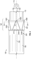
- FIGS. 2-5 a composite beam structure (beam structure) 100 ( FIGS. 4 and 5 ) is shown.
- FIGS. 2-4 show side views, and
- FIG. 5 shows a diametric cross-section.
- the structure is utilized in an aircraft such as the aircraft of FIGS. 1A-1B .
- An end piece 110 (shown in FIGS. 2 and 4-5 ) of the beam structure 100 has an axis 120, an end piece outer periphery surface 130 and a mating end 140 defining an end piece axial boundary (or axial end edge) 150.
- the end piece 110 extends axially from the end piece mating end 140 to an axial exterior end 160.
- a mechanical connector 170 shown in FIGS.
- the end piece 110 includes end piece wedge-shaped inner locking features 180 (for simplicity, a single locking feature 180A is shown in FIG. 2 , three locking features 180A-180C are shown, partially in hidden lines, in FIG. 4 , and four locking features 180A-180D are show in FIG. 5 )), which are end piece wedge-shaped bosses that are formed on the end piece outer periphery surface 130 at the end piece mating end 140 and spaced apart from one another. There can be more than one locking features 180 distributed in the hoop direction around the end piece 110.
- the end piece 110 is formed of a material that resists deformation under rotational and translational forces, which may be metal, alloy or other materials similarly satisfying corresponding strength criteria.
- the beam structure 100 includes a composite tube 190 (shown in FIGS. 2-5 ) that is formed of a material selected from one or more reinforced carbon, glass, and organic fibers or any of their combination, within either thermoset or thermoplastic polymeric matrix.
- the composite tube 190 is configured to surround at least a portion of the end piece mating end 140 to form a beam joint 200.
- Wedge-shaped imprints 210 (a single imprint 210A is shown in FIG. 3 ), corresponding to the wedge-shaped inner locking features 180 on the end piece mating end 140, are formed through the composite tube 190.
- the wedge-shaped imprints 210 define respective composite tube wedge-shaped depression surfaces 220 ( FIG. 5 ) about a composite tube inner periphery 235 ( FIG.
- composite tube wedge-shaped boss surfaces 230 (a single composite tube wedge-shaped boss surfaces 230A is shown in FIG. 3 , and three composite tube wedge-shaped boss surfaces 230A-230C are illustrated in part in FIG. 4 ) about a composite tube outer periphery 240.
- the wedge-shaped inner locking features 180 of the end piece 110 are covered by the composite tube wedge-shaped depression surfaces 220.
- a number of imprints 210 corresponds to a similar number of locking features 180.
- each of the wedge-shaped inner locking features 180 is triangular having a vertex surface portion 242 that is disposed along the axis 120 and is directed away from the end piece axial boundary 150 of the end piece mating end 140 of the end piece 110. More specifically, each of the wedge-shaped inner locking features 180 is configured as an isosceles triangle, oriented such that it is bisected by the axis 120. This configuration defines a first right triangular surface 244 and a second right triangular surface 246 oriented at an angle alpha ( ⁇ ) to the axis 120. The angle alpha ( ⁇ ) defines reaction forces R', normal to the first right triangle surface 24 and the second right triangular surface 246.
- R' are shown on example of applied external tension load N ( FIG. 2 ).
- R" are corresponding reactions to forces R' at composite tube 190 ( FIG. 3 ), equal to R' but directed in respectively opposite directions. Forces are reacted along the reaction axes R' that otherwise tend to pull the end piece 110 and composite tube 190 from one another or cause the same to rotate relative to one another.
- the angle alpha ( ⁇ ), number of locking features 180 and their sizes, and thus the reaction forces R' may be determined based on material characteristics and load conditions, to optimize a redistribution of such forces. This configuration minimizes a likelihood of mutual movement of composite tube 190 and end piece 110 under expected load conditions, such as axial, torsional and bending loads.
- force vector N is illustrated in FIGS. 2 and 3 , acting along opposing directions and at opposing ends of the beam structure 100.
- the vector N has the same value in either direction due to equilibrium conditions.
- FIGS. 6-7 again shown is the end piece 110 and the composite tube 190 of FIGS. 2-5 .
- FIG. 6 and 7 show a side and a diametric cross-sectional views respectively.
- the wedge-shaped inner locking features 180, the wedge-shaped imprints 210 that define the composite tube wedge-shaped boss surfaces 230, the end piece axial boundary 150 ( FIG. 6 ) of the end piece 110, and the mechanical connector 170 are also identified.
- An end cap 250 is secured to the composite tube outer periphery 240 at the beam joint 200.
- the end cap 250 is formed with wedge-shaped outer locking features 260A, 260B.
- the wedge-shaped outer locking features 260A, 260B abut adjacent ones of the composite tube wedge-shaped boss surfaces 230.
- the wedge-shaped outer locking features 260 are connected to one another by a collar portion 290 of the end cap 250 that surrounds the end piece 110.
- the collar portion 290 is adjacent to the beam joint 200.
- the end cap 250 is made of a material that resists deforming under rotational, and/or axial and/or bending loads.
- the end cap 250 is formed of, for example, metal or alloy, which may be the same or different material as the end piece 110.
- the end cap 250 is fastened to the end piece 110 with a fastener 295, which may be, for example, a nut and bolt connector, i.e., providing a nut and bolt connection therebetween. Number of such fasteners can be defined by, for examples, strength based criteria.
- the end cap 250 is fastened to the end piece 110 at a location that is spaced apart from the beam joint 200. In one embodiment an axial free end of the end cap 250 is fastened to an axial free end 310 of the end piece 110, i.e., spaced apart along the axis 120 from the end piece axial boundary 150.
- the configuration of the wedge-shaped inner and outer locking features 180, 260 may be modified by changing the angle alpha ( ⁇ ) defined by the first and second right triangular surfaces 244, 246 relative to the axis 120.
- the cross-sectional shape of the beam structure 100 is circular.
- the shape could also be square or other polygonal shape (triangular, pentagonal, hexagonal, etc.) or other closed-contour shape.
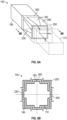
- FIGS. 8A-8B show a square version of the beam structure 100.
- the composite tube 190 is shown, and the end piece 110 and end cap 250 are illustrated schematically.
- At least two sets of wedge-shaped inner and outer locking features 180, 260 will react the rotational and translational forces, though a greater or lesser number of sets of the wedge-shaped inner and outer locking features 180, 260 is within the scope of the disclosure.
- the wedge-shaped inner and outer locking features 180, 260 may be on each planar surface 300 of a square or other polygonal shape.
- the end cap 250 is discontinuous in the hoop direction between the boss surfaces 280 about its perimeter along the beam joint 200. That is, the wedge-shaped outer locking features 180, 260 define an end cap outer boundary for the end cap 250.
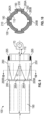
- FIGS. 9-10 show a version of the end cap 250 that is continuous about the perimeter of the beam joint 200.
- FIG. 9 and 10 show side and diametric cross-sectional views, respectively. Shown in these figures is the composite tube 190, the end piece 110 and the end cap 250 and the fastener 295 ( FIG. 9 ) of the beam structure 100.
- the end cap 250 has a complementary cross section shape to the composite tube outer periphery 240 about the beam joint 200.
- the end cap 250 axially adjacent to the collar 290, includes the end cap wedge-shaped outer locking features 160A, 160B, which are shaped as wedge-shaped depression surfaces.
- the end cap wedge-shaped outer locking features 260A, 260B interspaced between the end cap wedge-shaped outer locking features 260A, 260B are end cap wedge-shaped boss surfaces 265 (two of the end cap wedge-shaped boss surfaces 265A, 265B are labeled).
- the inner locking features 160, the composite tube boss surfaces 230 and the end cap boss surfaces 265 are circumferentially aligned and radially layered against one another.
- the end piece 110 is continuous about its perimeter between the wedge-shaped inner locking features 180 along the beam joint 200.
- FIG. 11 shows a side view of a version of the end piece 110 that is discontinuous about its perimeter between the wedge-shaped inner locking features 180 (three wedge-shaped locking features 180A-180C are labeled). That is, the wedge-shaped inner locking features 180 define the end piece axial boundary 150 at the mating end 140. Further labeled in FIG. 11 is the axis 120 and the mechanical connector 170 at the axial exterior end 160, the locking features 180 (a single locking feature 180A is shown).
- FIG. 12 shows an embodiment in which the end piece of FIG. 11 is mated with the composite tube 190 and the end cap 250 as shown in FIG. 7 .
- FIG. 13 shows an embodiment in which the end piece of FIG. 11 is mated with the composite tube 190 and the end cap 250 as shown in FIG. 9 .
- FIG. 13 shows an alternate version of section B1-B1 of FIG. 9 .
- Both FIGS. 12 and 13 represent diametric cross-sectional views.
- Each of these figures illustrates the beam joint 200 of the beam 100, the end piece 100, the end piece boundary 150 formed by the embodiment of the end piece illustrated in FIG. 11 , the composite tube 190 and the end cap 250.
- FIG. 12 shows an embodiment in which the end piece of FIG. 11 is mated with the composite tube 190 and the end cap 250 as shown in FIG. 7 .
- FIG. 13 shows an alternate version of section B1-B1 of FIG. 9 .
- Both FIGS. 12 and 13 represent diametric cross-sectional views.
- the inner locking features 180 and the outer locking features 260 circumferentially alternate with one another.
- the inner locking features 160, the composite tube boss surfaces 230 and the end cap boss surfaces 265 are circumferentially aligned and radially layered against one another.
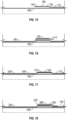
- FIGS. 15-18 show axial cross-sectional views.
- the method includes positioning the end piece 110 on a mandrel 400.
- the end piece 110 has an end piece outer periphery surface 130, and a mating end 140.
- the end piece 110 includes wedge-shaped inner locking features 180 that are formed to project outwardly on the end piece outer periphery surface 130 at the end piece mating end 140 and are spaced apart from one another.
- the method includes positioning an insert 410 about the mating end 140 for the end piece 110 and positioning the composite tube 190 on the mandrel 400 so that the composite tube 190 surrounds at least a portion of the end piece mating end 140, with the insert 410 therebetween, to form a beam joint 200.
- the insert 410 provides spacing for the forming the composite tube 190 around the mandrel 400 and the end piece 110, e.g., by different appropriate methods of making composite tubes, such as, among others, by filament-winding (as one example) or automated fiber placing (AFP) (as another example).
- the insert 410 is removed once the composite tube 190 is formed.
- the insert 410 is optional and can be avoided if there is sufficient room for forming the composite mating end 140.
- the method includes clamping the composite tube 190 against the end piece mating end 140 to form wedge-shaped imprints 210 through the composite tube 190 corresponding to the wedge-shaped inner locking features 180 on the end piece mating end 140.
- the wedge-shaped imprints 210 define composite tube wedge-shaped depression surfaces 220 about the composite tube inner periphery 235 ( FIG. 6 ) and composite tube wedge-shaped boss surfaces 230 ( FIG. 6 ) about the composite tube outer periphery 240.
- the wedge-shaped inner locking features 180 on the end piece mating end 140 are covered by the composite tube wedge-shaped depression surfaces 220.
- thermoplastic composite materials are used for the composite tube 190
- clamping devices can be heated for better manufacturability. Once the composite tube 190 is cured for thermoset composite materials or solidified for thermoplastic composite materials (shown in block 545), any clamping implements may be removed.
- the method includes securing the end cap 250 to the end piece 110. With this configuration, wedge-shaped outer locking features 260 of the end cap 250 abut adjacent ones of the composite tube wedge-shaped boss surfaces 230. As indicated, the end cap 250 may be secured to the end piece 110 with a fastener 295. As shown in block 550, the method includes removing the beam structure 100 and the mandrel 400 from one another. Sequence of blocks 540, 545 and 550 can be different, depending on specifics of manufacturing implementation.
Landscapes
- Engineering & Computer Science (AREA)
- Mechanical Engineering (AREA)
- General Engineering & Computer Science (AREA)
- Physics & Mathematics (AREA)
- Geometry (AREA)
- Chemical & Material Sciences (AREA)
- Composite Materials (AREA)
- Moulding By Coating Moulds (AREA)
- Mutual Connection Of Rods And Tubes (AREA)
- Rod-Shaped Construction Members (AREA)
- Aviation & Aerospace Engineering (AREA)
Applications Claiming Priority (2)
| Application Number | Priority Date | Filing Date | Title |
|---|---|---|---|
| US16/784,868 US11892030B2 (en) | 2020-02-07 | 2020-02-07 | Composite beam joint with wedge-shaped inner and outer locking features |
| EP21155870.5A EP3862175B1 (de) | 2020-02-07 | 2021-02-08 | Herstellungsverfahren einer verbundträgerstruktur |
Related Parent Applications (1)
| Application Number | Title | Priority Date | Filing Date |
|---|---|---|---|
| EP21155870.5A Division EP3862175B1 (de) | 2020-02-07 | 2021-02-08 | Herstellungsverfahren einer verbundträgerstruktur |
Publications (2)
| Publication Number | Publication Date |
|---|---|
| EP4245659A2 true EP4245659A2 (de) | 2023-09-20 |
| EP4245659A3 EP4245659A3 (de) | 2023-11-01 |
Family
ID=74561835
Family Applications (2)
| Application Number | Title | Priority Date | Filing Date |
|---|---|---|---|
| EP23191200.7A Pending EP4245659A3 (de) | 2020-02-07 | 2021-02-08 | Verbundträgerverbindung mit keilförmigen inneren und äusseren verriegelungsmerkmalen |
| EP21155870.5A Active EP3862175B1 (de) | 2020-02-07 | 2021-02-08 | Herstellungsverfahren einer verbundträgerstruktur |
Family Applications After (1)
| Application Number | Title | Priority Date | Filing Date |
|---|---|---|---|
| EP21155870.5A Active EP3862175B1 (de) | 2020-02-07 | 2021-02-08 | Herstellungsverfahren einer verbundträgerstruktur |
Country Status (2)
| Country | Link |
|---|---|
| US (1) | US11892030B2 (de) |
| EP (2) | EP4245659A3 (de) |
Families Citing this family (1)
| Publication number | Priority date | Publication date | Assignee | Title |
|---|---|---|---|---|
| US20250091298A1 (en) * | 2023-09-20 | 2025-03-20 | B/E Aerospace, Inc. | Joints for composite laminated panels and beams |
Citations (4)
| Publication number | Priority date | Publication date | Assignee | Title |
|---|---|---|---|---|
| EP2229540A1 (de) | 2007-11-23 | 2010-09-22 | Crompton Technology Group Ltd. | Verbinder für eine röhrenförmige verbundwelle |
| EP3133298A1 (de) | 2015-08-21 | 2017-02-22 | Crompton Technology Group Limited | Verbinder |
| EP3427927A1 (de) | 2017-07-11 | 2019-01-16 | Goodrich Corporation | Verbundgelenkanordnung |
| WO2021046310A1 (en) | 2019-09-05 | 2021-03-11 | Albany Engineered Composites, Inc. | Method for producing a positive-locking load application for a tension-compression rod and a tension-compression rod |
Family Cites Families (16)
| Publication number | Priority date | Publication date | Assignee | Title |
|---|---|---|---|---|
| SE343480B (de) * | 1970-07-06 | 1972-03-13 | New Invent Sa | |
| US3778185A (en) | 1972-08-28 | 1973-12-11 | United Aircraft Corp | Composite strut joint construction |
| US4523872A (en) * | 1981-08-12 | 1985-06-18 | Grumman Aerospace Corporation | Torsion resistant grooved joint |
| FR2675563B1 (fr) | 1991-04-22 | 1993-08-27 | Aerospatiale | Procede d'assemblage mecanique d'un tube en materiau composite et d'une piece metallique et assemblage ainsi realise. |
| FR2696513B1 (fr) * | 1992-10-06 | 1994-12-23 | Gkn Automotive Ag | Organe mécanique tubulaire tel qu'un arbre de transmission de véhicule automobile. |
| US6352385B1 (en) * | 2000-07-31 | 2002-03-05 | General Electric Company | Mechanical coupling for cooperating rotatable members |
| US6855061B2 (en) * | 2002-04-04 | 2005-02-15 | Dana Corporation | Vehicular driveshaft assembly |
| DE102008017679A1 (de) * | 2008-04-08 | 2009-10-15 | Bayerische Motoren Werke Aktiengesellschaft | Kopplungseinrichtung bzw. Antriebsstrang für Fahrzeuge mit einer Kopplungseinrichtung |
| US10634473B2 (en) * | 2014-01-29 | 2020-04-28 | Raytheon Company | Internally coupleable joint |
| EP3081822B1 (de) * | 2015-04-16 | 2019-08-28 | AIRBUS HELICOPTERS DEUTSCHLAND GmbH | Hybride metall-verbundstoff-antriebswelleneinheit und verfahren zur herstellung davon |
| DE102015225180A1 (de) * | 2015-12-15 | 2017-06-22 | Schaeffler Technologies AG & Co. KG | Flansch mit angeformter Welle |
| GB2546280A (en) | 2016-01-12 | 2017-07-19 | Crompton Tech Group Ltd | Composite tubular structure |
| US10539174B2 (en) | 2016-12-12 | 2020-01-21 | Goodrich Corporation | Composite joint assembly |
| US10823213B2 (en) | 2018-06-08 | 2020-11-03 | Goodrich Corporation | Composite joint assembly |
| US11396904B2 (en) * | 2018-10-29 | 2022-07-26 | Hamilton Sundstrand Corporation | Composite drive shafts |
| JP7223064B2 (ja) * | 2021-06-11 | 2023-02-15 | 株式会社三條機械製作所 | シャフトの製造方法 |
-
2020
- 2020-02-07 US US16/784,868 patent/US11892030B2/en active Active
-
2021
- 2021-02-08 EP EP23191200.7A patent/EP4245659A3/de active Pending
- 2021-02-08 EP EP21155870.5A patent/EP3862175B1/de active Active
Patent Citations (4)
| Publication number | Priority date | Publication date | Assignee | Title |
|---|---|---|---|---|
| EP2229540A1 (de) | 2007-11-23 | 2010-09-22 | Crompton Technology Group Ltd. | Verbinder für eine röhrenförmige verbundwelle |
| EP3133298A1 (de) | 2015-08-21 | 2017-02-22 | Crompton Technology Group Limited | Verbinder |
| EP3427927A1 (de) | 2017-07-11 | 2019-01-16 | Goodrich Corporation | Verbundgelenkanordnung |
| WO2021046310A1 (en) | 2019-09-05 | 2021-03-11 | Albany Engineered Composites, Inc. | Method for producing a positive-locking load application for a tension-compression rod and a tension-compression rod |
Also Published As
| Publication number | Publication date |
|---|---|
| EP3862175B1 (de) | 2023-09-06 |
| EP3862175A1 (de) | 2021-08-11 |
| EP4245659A3 (de) | 2023-11-01 |
| US11892030B2 (en) | 2024-02-06 |
| US20210245864A1 (en) | 2021-08-12 |
Similar Documents
| Publication | Publication Date | Title |
|---|---|---|
| EP3159257B1 (de) | Drehverbindung mit aktuator, rahmenbausatz und rahmen mit drehverbindungen | |
| US9707748B2 (en) | Printed spacecraft separation system | |
| EP3098463B1 (de) | Drehgelenk, rahmenkonstruktionskit und verfahren zur herstellung eines drehgelenks | |
| EP2353997B1 (de) | Verbindungsanordnung für die seitlichen Kästen eines Höhenleitwerks mit rohrförmigem zentralen Kasten und Herstellungsverfahren für einen solchen Kasten | |
| WO2019114885A1 (de) | Flugmodul | |
| US20140137700A1 (en) | Component for absorbing and/or transmitting mechanical forces and/or moments, method for producing same and use thereof | |
| EP3156324B1 (de) | Hybridmetall-/verbundkolbenbodengelenk | |
| EP3076048A2 (de) | Zusammengesetzte betätigungsstangenendbaugruppe | |
| EP3862175B1 (de) | Herstellungsverfahren einer verbundträgerstruktur | |
| EP3165450A1 (de) | Verbinder, drehverbindung, rahmenkontruktionskit und rahmen | |
| EP3051148A1 (de) | Stellantrieb mit einer kolbenstange aus verbundwerkstoff und einem kolben aus metall | |
| EP3228534B1 (de) | Druckschottvorrichtung | |
| US20240326350A1 (en) | Metal composite joints for composite rods | |
| US11732746B2 (en) | Drive shaft with an integrated flange | |
| CN109514772B (zh) | 具有各向异性的热性能的模具工具 | |
| US20200378423A1 (en) | Hybrid metallic/composite joint with enhanced strength | |
| EP3306118A1 (de) | Hybrides metall-/verbundgelenk mit verbesserter leistung | |
| US5417549A (en) | Expandable spar filler block device | |
| EP3013688B1 (de) | Systeme und verfahren zur blattbefestigung | |
| US20190131781A1 (en) | Bend radius device for flexible tube | |
| GB2279085A (en) | Termination of thermoplastic composite tensile members | |
| EP3680093A1 (de) | Hybride metall-/verbundbauteil für drehmoment-, biege-, scher- und axialbelastung und verfahren zu dessen herstellung | |
| EP3895936B1 (de) | Flugzeugsitzrahmen mit verbessertem dynamischem verhalten | |
| US6793479B1 (en) | Remotely actuated localized pressure and heat apparatus and method of use |
Legal Events
| Date | Code | Title | Description |
|---|---|---|---|
| PUAI | Public reference made under article 153(3) epc to a published international application that has entered the european phase |
Free format text: ORIGINAL CODE: 0009012 |
|
| STAA | Information on the status of an ep patent application or granted ep patent |
Free format text: STATUS: THE APPLICATION HAS BEEN PUBLISHED |
|
| AC | Divisional application: reference to earlier application |
Ref document number: 3862175 Country of ref document: EP Kind code of ref document: P |
|
| AK | Designated contracting states |
Kind code of ref document: A2 Designated state(s): AL AT BE BG CH CY CZ DE DK EE ES FI FR GB GR HR HU IE IS IT LI LT LU LV MC MK MT NL NO PL PT RO RS SE SI SK SM TR |
|
| REG | Reference to a national code |
Ref country code: DE Ref legal event code: R079 Free format text: PREVIOUS MAIN CLASS: B64C0025340000 Ipc: B29C0070860000 |
|
| PUAL | Search report despatched |
Free format text: ORIGINAL CODE: 0009013 |
|
| AK | Designated contracting states |
Kind code of ref document: A3 Designated state(s): AL AT BE BG CH CY CZ DE DK EE ES FI FR GB GR HR HU IE IS IT LI LT LU LV MC MK MT NL NO PL PT RO RS SE SI SK SM TR |
|
| RIC1 | Information provided on ipc code assigned before grant |
Ipc: B29C 65/64 20060101ALI20230922BHEP Ipc: B64C 25/34 20060101ALI20230922BHEP Ipc: B29L 31/00 20060101ALI20230922BHEP Ipc: B29C 65/56 20060101ALI20230922BHEP Ipc: B64C 25/00 20060101ALI20230922BHEP Ipc: B29L 31/06 20060101ALI20230922BHEP Ipc: F16C 7/02 20060101ALI20230922BHEP Ipc: F16B 7/04 20060101ALI20230922BHEP Ipc: B29D 99/00 20100101ALI20230922BHEP Ipc: B29C 65/00 20060101ALI20230922BHEP Ipc: B29C 70/86 20060101AFI20230922BHEP |
|
| STAA | Information on the status of an ep patent application or granted ep patent |
Free format text: STATUS: REQUEST FOR EXAMINATION WAS MADE |
|
| 17P | Request for examination filed |
Effective date: 20240430 |
|
| RBV | Designated contracting states (corrected) |
Designated state(s): AL AT BE BG CH CY CZ DE DK EE ES FI FR GB GR HR HU IE IS IT LI LT LU LV MC MK MT NL NO PL PT RO RS SE SI SK SM TR |
|
| STAA | Information on the status of an ep patent application or granted ep patent |
Free format text: STATUS: EXAMINATION IS IN PROGRESS |
|
| 17Q | First examination report despatched |
Effective date: 20250224 |