EP4245580A1 - Devices, systems, and vehicles for providing ventilation - Google Patents
Devices, systems, and vehicles for providing ventilation Download PDFInfo
- Publication number
- EP4245580A1 EP4245580A1 EP22205037.9A EP22205037A EP4245580A1 EP 4245580 A1 EP4245580 A1 EP 4245580A1 EP 22205037 A EP22205037 A EP 22205037A EP 4245580 A1 EP4245580 A1 EP 4245580A1
- Authority
- EP
- European Patent Office
- Prior art keywords
- section
- duct
- vent
- seat
- controller
- Prior art date
- Legal status (The legal status is an assumption and is not a legal conclusion. Google has not performed a legal analysis and makes no representation as to the accuracy of the status listed.)
- Pending
Links
Images



Classifications
-
- B—PERFORMING OPERATIONS; TRANSPORTING
- B60—VEHICLES IN GENERAL
- B60H—ARRANGEMENTS OF HEATING, COOLING, VENTILATING OR OTHER AIR-TREATING DEVICES SPECIALLY ADAPTED FOR PASSENGER OR GOODS SPACES OF VEHICLES
- B60H1/00—Heating, cooling or ventilating devices
- B60H1/00642—Control systems or circuits; Control members or indication devices for heating, cooling or ventilating devices
- B60H1/00814—Control systems or circuits characterised by their output, for controlling particular components of the heating, cooling or ventilating installation
- B60H1/00821—Control systems or circuits characterised by their output, for controlling particular components of the heating, cooling or ventilating installation the components being ventilating, air admitting or air distributing devices
- B60H1/00864—Ventilators and damper doors
-
- B—PERFORMING OPERATIONS; TRANSPORTING
- B60—VEHICLES IN GENERAL
- B60H—ARRANGEMENTS OF HEATING, COOLING, VENTILATING OR OTHER AIR-TREATING DEVICES SPECIALLY ADAPTED FOR PASSENGER OR GOODS SPACES OF VEHICLES
- B60H1/00—Heating, cooling or ventilating devices
- B60H1/00271—HVAC devices specially adapted for particular vehicle parts or components and being connected to the vehicle HVAC unit
- B60H1/00285—HVAC devices specially adapted for particular vehicle parts or components and being connected to the vehicle HVAC unit for vehicle seats
-
- B—PERFORMING OPERATIONS; TRANSPORTING
- B60—VEHICLES IN GENERAL
- B60H—ARRANGEMENTS OF HEATING, COOLING, VENTILATING OR OTHER AIR-TREATING DEVICES SPECIALLY ADAPTED FOR PASSENGER OR GOODS SPACES OF VEHICLES
- B60H1/00—Heating, cooling or ventilating devices
- B60H1/00007—Combined heating, ventilating, or cooling devices
-
- B—PERFORMING OPERATIONS; TRANSPORTING
- B60—VEHICLES IN GENERAL
- B60H—ARRANGEMENTS OF HEATING, COOLING, VENTILATING OR OTHER AIR-TREATING DEVICES SPECIALLY ADAPTED FOR PASSENGER OR GOODS SPACES OF VEHICLES
- B60H1/00—Heating, cooling or ventilating devices
- B60H1/00457—Ventilation unit, e.g. combined with a radiator
-
- B—PERFORMING OPERATIONS; TRANSPORTING
- B60—VEHICLES IN GENERAL
- B60H—ARRANGEMENTS OF HEATING, COOLING, VENTILATING OR OTHER AIR-TREATING DEVICES SPECIALLY ADAPTED FOR PASSENGER OR GOODS SPACES OF VEHICLES
- B60H1/00—Heating, cooling or ventilating devices
- B60H1/00507—Details, e.g. mounting arrangements, desaeration devices
-
- B—PERFORMING OPERATIONS; TRANSPORTING
- B60—VEHICLES IN GENERAL
- B60H—ARRANGEMENTS OF HEATING, COOLING, VENTILATING OR OTHER AIR-TREATING DEVICES SPECIALLY ADAPTED FOR PASSENGER OR GOODS SPACES OF VEHICLES
- B60H1/00—Heating, cooling or ventilating devices
- B60H1/00507—Details, e.g. mounting arrangements, desaeration devices
- B60H1/00557—Details of ducts or cables
- B60H1/00564—Details of ducts or cables of air ducts
-
- B—PERFORMING OPERATIONS; TRANSPORTING
- B60—VEHICLES IN GENERAL
- B60H—ARRANGEMENTS OF HEATING, COOLING, VENTILATING OR OTHER AIR-TREATING DEVICES SPECIALLY ADAPTED FOR PASSENGER OR GOODS SPACES OF VEHICLES
- B60H1/00—Heating, cooling or ventilating devices
- B60H1/00642—Control systems or circuits; Control members or indication devices for heating, cooling or ventilating devices
- B60H1/00814—Control systems or circuits characterised by their output, for controlling particular components of the heating, cooling or ventilating installation
- B60H1/00821—Control systems or circuits characterised by their output, for controlling particular components of the heating, cooling or ventilating installation the components being ventilating, air admitting or air distributing devices
- B60H1/00835—Damper doors, e.g. position control
- B60H1/00842—Damper doors, e.g. position control the system comprising a plurality of damper doors; Air distribution between several outlets
-
- B—PERFORMING OPERATIONS; TRANSPORTING
- B60—VEHICLES IN GENERAL
- B60H—ARRANGEMENTS OF HEATING, COOLING, VENTILATING OR OTHER AIR-TREATING DEVICES SPECIALLY ADAPTED FOR PASSENGER OR GOODS SPACES OF VEHICLES
- B60H1/00—Heating, cooling or ventilating devices
- B60H1/00642—Control systems or circuits; Control members or indication devices for heating, cooling or ventilating devices
- B60H1/00814—Control systems or circuits characterised by their output, for controlling particular components of the heating, cooling or ventilating installation
- B60H1/00821—Control systems or circuits characterised by their output, for controlling particular components of the heating, cooling or ventilating installation the components being ventilating, air admitting or air distributing devices
- B60H1/00871—Air directing means, e.g. blades in an air outlet
-
- B—PERFORMING OPERATIONS; TRANSPORTING
- B60—VEHICLES IN GENERAL
- B60N—SEATS SPECIALLY ADAPTED FOR VEHICLES; VEHICLE PASSENGER ACCOMMODATION NOT OTHERWISE PROVIDED FOR
- B60N2/00—Seats specially adapted for vehicles; Arrangement or mounting of seats in vehicles
- B60N2/56—Heating or ventilating devices
- B60N2/5607—Heating or ventilating devices characterised by convection
- B60N2/5621—Heating or ventilating devices characterised by convection by air
- B60N2/5628—Heating or ventilating devices characterised by convection by air coming from the vehicle ventilation system, e.g. air-conditioning system
-
- B—PERFORMING OPERATIONS; TRANSPORTING
- B60—VEHICLES IN GENERAL
- B60H—ARRANGEMENTS OF HEATING, COOLING, VENTILATING OR OTHER AIR-TREATING DEVICES SPECIALLY ADAPTED FOR PASSENGER OR GOODS SPACES OF VEHICLES
- B60H1/00—Heating, cooling or ventilating devices
- B60H1/00007—Combined heating, ventilating, or cooling devices
- B60H1/00021—Air flow details of HVAC devices
- B60H2001/00114—Heating or cooling details
-
- B—PERFORMING OPERATIONS; TRANSPORTING
- B60—VEHICLES IN GENERAL
- B60H—ARRANGEMENTS OF HEATING, COOLING, VENTILATING OR OTHER AIR-TREATING DEVICES SPECIALLY ADAPTED FOR PASSENGER OR GOODS SPACES OF VEHICLES
- B60H1/00—Heating, cooling or ventilating devices
- B60H1/00271—HVAC devices specially adapted for particular vehicle parts or components and being connected to the vehicle HVAC unit
- B60H2001/003—Component temperature regulation using an air flow
Definitions
- a device in an illustrative embodiment, includes a seat having a first section of duct having a first end, a second section of duct couplable to the first section of duct, and a third section of duct couplable to the first section of duct.
- the second section of duct connects at a first end to an air supply source and at a second end to the first end of the first section of duct.
- the third section of duct includes a vent (e.g., an exhaust vent) configured to direct air received from the air supply source in a direction aft of the seat.
- a system in another illustrative embodiment, includes an interface device configured to receive instructions from a user, an air supply unit, a controller configured to command the air supply unit to output air at a particular temperature responsive to the received instructions, a seat having first section of duct having a first end, a second section of duct that connects at a first end to an air supply source and at a second end to the first end of the first section of duct and a third section of duct configured to connect to the first section of duct.
- the third section of duct includes a vent (e.g., an exhaust vent) configured to direct air received from the air supply source in a direction aft of the seat.
- HVAC heating, ventilation and air conditioning
- an illustrative vehicle 40 includes a cabin 42, a cargo bay 44 disposed aft of the cabin 42 (i.e., in a direction opposite the front of the vehicle), and a seat and cargo bay heating, ventilation, and air conditioning (HVAC) system 50.
- the cargo bay 44 may be other areas in need of venting, cooling, and/or heating, such as, without limitation, a seating area, an inside or an outside sleeping area, a living area, a heating unit, a cooling unit (food/drink cooler), a work area, a storage area, or the like.
- the HVAC system 50 may provide simultaneous heating, venting, or cooling to a seat 80 located in the cabin 42 and the cargo bay 44.
- the HVAC system 50 may include an interface device 62, an air supply source, and a controller 60.
- the air supply source may be an HVAC unit 68.
- the controller 60 is configured to command the HVAC unit 68 to output air at a particular temperature, recirculate air, and/or pump in exterior air responsive to instructions received by the interface device 62.
- the cabin 42 includes a first section(s) of duct 94 disposed within the seat 80.
- the first section(s) of duct 94 includes a first end.
- the cabin 42 also includes a second section of duct 82 that connects at a first end to the HVAC unit 68 and at a second end to the first end of the first section(s) of duct 94.
- the cabin 42 also includes a third section of duct 88 that connects to a distal end of the first section(s) of duct 94.
- the third section of duct 88 includes an exhaust vent 90 configured to direct air received from the HVAC unit 68 in a direction aft of the seat 80 (e.g., in a direction opposite the direction of a seat back) towards an aft section of the vehicle 40, such as, without limitation, the cargo bay 44.
- the exhaust vent 90 may be connected to the third section of duct 88 via a swivel device or mechanism, such as, without limitation, a hinge, a pivot pin, or comparable device.
- the vehicle 40 may include a motor vehicle driven by wheels and/or tracks, such as, without limitation, an automobile, a truck, a sport utility vehicle (SUV), a van, and the like.
- the vehicle 40 may include a marine vessel such as, without limitation, a boat, a ship, a submarine, a submersible, an autonomous underwater vehicle (AUV), and the like.
- the vehicle 40 may include an aircraft such as, without limitation, a fixed wing aircraft, a rotary wing aircraft, and a lighter-than-air (LTA) craft.
- LTA lighter-than-air
- the HVAC unit 68 includes a heat exchanger, a blower motor, an evaporator coil, and a thermostat. HVAC systems are well known in the art and no further explanation is necessary for a person of skill in the art to understand disclosed subject matter.
- the interface device 62 may include mechanical buttons, switches, voice recognition capabilities, gesture recognition capabilities, or may include selectable graphical user interface features presented on a vehicle display device(s) or via an application program executable by a person electronic device.
- the interface device 62 allows a vehicle operator to select heating, venting, and/or cooling operational modes of the vehicle seat 80 and/or the cargo bay 44.
- the interface device 62 may also include control switches located on or near the seat 80.
- the interface device 62 may be directly connected to the fan 64, the vent motor(s) 92 and/or the diverter motor 112.
- the control switches are configured to activate the fan 64, the vent motor(s) 92 and/or the diverter motor 112.
- the illustrative cabin 42 includes a seat and cargo venting device 52.
- the seat and cargo venting device 52 includes the seat 80 having a seat section 86 and a seatback section 84.
- the seat 80 is slidably attached to a seat base 70 or the seat 80 and the seat base 70 are slidably attached to a floor of the cabin 42.
- the seat 80 and/or the seat base 70 includes first duct sections 94 of the seat and cargo venting device 52.
- the seat and cargo venting device 52 also includes a second duct section 82 and a third duct section 88.
- the second duct section 82 connects at a proximal end to the HVAC unit 68 of the vehicle 40.
- a distal end of the second duct section 82 is connected to a proximal end of the first duct sections 94.
- the third duct section 88 connects to a distal end of the first duct sections 94.
- the third duct section 88 may extend distally and/or vertically to a vent 90.
- the third duct section 88 may be attached to or placed within an aft bulkhead of the cabin 42. The bulkhead separates the cabin 42 from the cargo bay 44.
- the interface device 62 may include an occupancy detection sensor (ODS) 74 that detects a person seated in the seat 80.
- ODS occupancy detection sensor
- the ODS 74 may pass the seat occupancy detection information to the controller 60 or directly to the fan 64, the vent motor(s) 92 and/or the diverter motor 112 in the form of an activation signal.
- the diverter 96 includes an aft port that connects to a proximal end of the third duct section 88.
- the diverter 96 also includes a vertical port configured to attach to a bottom of the first vertical section 102.
- the seat base outlet 98 extends from a top end of the first vertical section 102.
- the second vertical section 104 extends vertically from the first vertical section 102 and is attached to the seat back outlet 100.
- the first vertical section 102 and the second vertical section 104 flex/expand as the seat section 86 and the seatback section 84 are tilted, either manually or via seat motors.
- the diverter motor 112 may be located on the outside of the diverter 96 with a shaft extending into the diverter 96 to make rotary contact with the flapper valve 110.
- the hinged flapper valve 110 may also be attached to a manual level located external to the diverter 96 that is easily accessible to an operator of vehicle 30 while sitting in the seat 80.
- the diverter 96 may include other types of diverter valves, such as, without limitation, rotary vane valves and the like. Diverters are well known in the art and no further explanation is necessary for a person of skill in the art to understand disclosed subject matter.
- a fan 64 is located within the second duct section 82, the base section 106, the diverter 96, or the third duct section 88.
- the fan 64 receives power via a switch controlled by the controller 60 or the interface device 62.
- the exhaust vent 90 is rotatably attached to a distal end of the third duct section 88.
- the exhaust vent 90 may be mounted at a pivot point, such as, without limitation, a pivot pin or hinge, to the third duct section 88.
- the exhaust vent 90 may also include rotatable vertical and/or horizontal louvers.
- the louvers may include devices for manually operating the louvers.
- the exhaust vent 90 may also include a motor(s) 92 that is attached to the louvers.
- the motor(s) 92 may connect between the third duct section 88 and the exhaust vent 90 thereby causing the exhaust vent 90 to rotate about the pivot point for directing air flow coming out of the exhaust vent 90.
- the motor(s) 92 may be controlled by the controller 60, by a switch controlled by the controller 60, and/or the interface device 62.
- the motor(s) 92 may be an electrical servomotor or comparable device.
- an additional vent 72 is located on a vertical section of the third duct section 88.
- the additional vent 72 may be directed at a passenger area/seat located in the cabin 42.
- the additional vent 72 may include louvers that are directed at the passenger area or includes louvers that may be manually or automatically controlled to direct air at the passenger area.
- the additional vent 72 may include a vent motor(s), similar to the vent motor(s) 92, for controlling operation of the louvers of the additional vent 72.
- the louvers may include devices for manually operating the louvers.
- the louvers of the additional vent 72 may be positioned to block airflow, to allow uninhibited airflow, and to allow airflow at any angle from the uninhibited airflow.
- the vent motor(s) for the additional vent 72 may be controlled by the controller 60 and/or the interface device 62, which may include an OBS located in a passenger seat.
- a data processing system generally includes one or more of a system unit housing, a video display device, memory such as volatile or non-volatile memory, processors such as microprocessors or digital signal processors, computational entities such as operating systems, drivers, graphical user interfaces, and application programs, one or more interactive devices (e.g., a touch pad, a touch screen, etc.), and/or control systems including feedback loops and control motors (e.g., feedback for sensing position and/or velocity; control motors for moving and/or adjusting components and/or quantities).
- a data processing system may be implemented utilizing suitable commercially available components, such as those typically found in data computing/communication and/or network computing/communication systems.
- controller may refer to a collection of one or more components that are arranged in a particular manner, or a collection of one or more general-purpose components that may be configured to operate in a particular manner at one or more particular points in time, and/or also configured to operate in one or more further manners at one or more further times.
- Reconfigurable and/or controllable components are capable of being configured as a first controller that has a first purpose, then a second controller that has a second purpose and then, a third controller that has a third purpose, and so on.
- the transition of a reconfigurable and/or controllable component may occur in as little as a few nanoseconds, or may occur over a period of minutes, hours, or days.
- the controller may no longer be capable of carrying out that first purpose until it is reconfigured.
- a controller may switch between configurations as different components/modules in as little as a few nanoseconds.
- a controller may reconfigure on-the-fly, e.g., the reconfiguration of a controller from a first controller into a second controller may occur just as the second controller is needed.
- a controller may reconfigure in stages, e.g., portions of a first controller that are no longer needed may reconfigure into the second controller even before the first controller has finished its operation. Such reconfigurations may occur automatically, or may occur through prompting by an external source, whether that source is another component, an instruction, a signal, a condition, an external stimulus, or similar.
- an example includes or recites multiple components/modules
- the example includes the possibility that the same hardware may implement more than one of the recited components/modules, either contemporaneously or at discrete times or timings.
- the implementation of multiple components/modules, whether using more components/modules, fewer components/modules, or the same number of components/modules as the number of components/modules, is merely an implementation choice and does not generally affect the operation of the components/modules themselves.
- any recitation of multiple discrete components/modules in this disclosure includes implementations of those components/modules as any number of underlying components/modules, including, but not limited to, a single component/module that reconfigures itself over time to carry out the functions of multiple components/modules, and/or multiple components/modules that similarly reconfigure, and/or special purpose reconfigurable components/modules.
- one or more components may be referred to herein as “configured to,” “configured by,” “configurable to,” “operable/operative to,” “adapted/adaptable,” “able to,” “conformable/conformed to,” etc.
- configured to generally encompass active-state components and/or inactive-state components and/or standby-state components, unless context requires otherwise.
- ASICs Application Specific Integrated Circuits
- FPGAs Field Programmable Gate Arrays
- DSPs digital signal processors
- ASICs Application Specific Integrated Circuits
- FPGAs Field Programmable Gate Arrays
- DSPs digital signal processors
- aspects of the embodiments disclosed herein, in whole or in part, can be equivalently implemented in integrated circuits, as one or more computer programs running on one or more computers (e.g., as one or more programs running on one or more computer systems), as one or more programs running on one or more processors (e.g., as one or more programs running on one or more microprocessors), as firmware, or as virtually any combination thereof, limited to patentable subject matter under 35 U.S.C.
- Examples of a signal bearing medium include, but are not limited to, the following: a recordable type medium such as a floppy disk, a hard disk drive, a Compact Disc (CD), a Digital Video Disk (DVD), a digital tape, a computer memory, etc.; and a transmission type medium such as a digital and/or an analog communication medium (e.g., a fiber optic cable, a waveguide, a wired communications link, a wireless communication link (e.g., transmitter, receiver, transmission logic, reception logic, etc.), etc.).
- a recordable type medium such as a floppy disk, a hard disk drive, a Compact Disc (CD), a Digital Video Disk (DVD), a digital tape, a computer memory, etc.
- a transmission type medium such as a digital and/or an analog communication medium (e.g., a fiber optic cable, a waveguide, a wired communications link, a wireless communication link (e.g., transmitter, receiver, transmission logic, reception
Landscapes
- Engineering & Computer Science (AREA)
- Mechanical Engineering (AREA)
- Physics & Mathematics (AREA)
- Thermal Sciences (AREA)
- Power Engineering (AREA)
- Aviation & Aerospace Engineering (AREA)
- Transportation (AREA)
- Air-Conditioning For Vehicles (AREA)
Abstract
Various disclosed embodiments include illustrative devices, systems, and vehicles for heating, ventilation and air conditioning (HVAC) functions for an area remote from an HVAC system. In an illustrative embodiment, a device includes a seat having a first section of duct having a first end, a second section of duct couplable to the first section of duct, and a third section of duct couplable to the first section of duct. The second section of duct connects at a first end to an air supply source and at a second end to the first end of the first section of duct. The third section of duct includes an exhaust vent configured to direct air received from the air supply source in a direction aft of the seat.
Description
- The present disclosure relates to vehicle climate control. The statements in this section merely provide background information related to the present disclosure and may not constitute prior art.
- In vehicles with a cargo space or areas without direct heating/cooling, air convection, not conditioning, such as with roof fans may be used to control temperature. These solutions do not heat or cool the air. To perform heating and/or cooling in zones separated from a cabin by a wall/door/closure, an entirely separate heating, ventilation, and air conditioning system is used.
- Various disclosed embodiments include illustrative devices, systems, and vehicles for heating, ventilation and air conditioning (HVAC) functions for an area remote from an HVAC system.
- In an illustrative embodiment, a device includes a seat having a first section of duct having a first end, a second section of duct couplable to the first section of duct, and a third section of duct couplable to the first section of duct. The second section of duct connects at a first end to an air supply source and at a second end to the first end of the first section of duct. The third section of duct includes a vent (e.g., an exhaust vent) configured to direct air received from the air supply source in a direction aft of the seat.
- In another illustrative embodiment, a system includes an interface device configured to receive instructions from a user, an air supply unit, a controller configured to command the air supply unit to output air at a particular temperature responsive to the received instructions, a seat having first section of duct having a first end, a second section of duct that connects at a first end to an air supply source and at a second end to the first end of the first section of duct and a third section of duct configured to connect to the first section of duct. The third section of duct includes a vent (e.g., an exhaust vent) configured to direct air received from the air supply source in a direction aft of the seat.
- In another illustrative embodiment, a vehicle includes a cabin, a cargo bay disposed aft of the cabin, an interface device configured to receive instructions from a user, an air supply unit, a controller configured to command the air supply unit to output air at a particular temperature responsive to the received instructions, a seat disposed in the cabin, wherein the seat includes a first section of duct having a first end, a second section of duct that connects at a first end to an air supply source and at a second end to the first end of the first section of duct, and a third section of duct that connects to the first section of duct. The third section of duct includes a vent (e.g., an exhaust vent) configured to direct air received from the air supply source in a direction aft of the seat.
- The foregoing summary is illustrative only and is not intended to be in any way limiting. In addition to the illustrative aspects, embodiments, and features described above, further aspects, embodiments, and features will become apparent by reference to the drawings and the following detailed description.
- Illustrative embodiments are illustrated in referenced figures of the drawings. It is intended that the embodiments and figures disclosed herein are to be considered illustrative rather than restrictive.
-
FIGURE 1 is a perspective view of an illustrative vehicle with a combined cabin and cargo bay heating, ventilation, and air conditioning (HVAC) system. -
FIGURE 2 is a block diagram of an illustrative HVAC system used in the vehicle ofFIGURE 1 . -
FIGURE 3 is a perspective view of a portion of the HVAC system used in the vehicle ofFIGURE 1 . -
FIGURE 4 is a perspective view of components of the HVAC system ofFIGURE 3 . -
FIGURE 5 is a perspective, partial x-ray view of the components ofFIGURE 3 . -
FIGURE 6 is a perspective view of a diverter included within the components ofFIGURE 5 . -
FIGURE 7 is a cross-sectional view of the diverter ofFIGURE 6 . -
FIGURE 8 is a perspective view of an aft component of the components ofFIGURE 5 . -
FIGURE 9 is another perspective view within the vehicle ofFIGURE 1 . - Like reference symbols in the various drawings generally indicate like elements.
- In the following detailed description, reference is made to the accompanying drawings, which form a part hereof. In the drawings, similar symbols typically identify similar components, unless context dictates otherwise. The illustrative embodiments described in the detailed description, drawings, and claims are not meant to be limiting. Other embodiments may be utilized, and other changes may be made, without departing from the spirit or scope of the subject matter presented here.
- Various disclosed embodiments include illustrative devices, systems, and vehicles for heating, ventilation and air conditioning (HVAC) functions for an area remote from an HVAC system.
- Given by way of non-limiting overview and referring to
FIGURES 1-5 , in various embodiments, anillustrative vehicle 40 includes acabin 42, acargo bay 44 disposed aft of the cabin 42 (i.e., in a direction opposite the front of the vehicle), and a seat and cargo bay heating, ventilation, and air conditioning (HVAC) system 50. Thecargo bay 44 may be other areas in need of venting, cooling, and/or heating, such as, without limitation, a seating area, an inside or an outside sleeping area, a living area, a heating unit, a cooling unit (food/drink cooler), a work area, a storage area, or the like. The HVAC system 50 may provide simultaneous heating, venting, or cooling to aseat 80 located in thecabin 42 and thecargo bay 44. The HVAC system 50 may include an interface device 62, an air supply source, and acontroller 60. The air supply source may be anHVAC unit 68. Thecontroller 60 is configured to command theHVAC unit 68 to output air at a particular temperature, recirculate air, and/or pump in exterior air responsive to instructions received by the interface device 62. Thecabin 42 includes a first section(s) ofduct 94 disposed within theseat 80. The first section(s) ofduct 94 includes a first end. Thecabin 42 also includes a second section ofduct 82 that connects at a first end to theHVAC unit 68 and at a second end to the first end of the first section(s) ofduct 94. Thecabin 42 also includes a third section ofduct 88 that connects to a distal end of the first section(s) ofduct 94. The third section ofduct 88 includes anexhaust vent 90 configured to direct air received from theHVAC unit 68 in a direction aft of the seat 80 (e.g., in a direction opposite the direction of a seat back) towards an aft section of thevehicle 40, such as, without limitation, thecargo bay 44. Theexhaust vent 90 may be connected to the third section ofduct 88 via a swivel device or mechanism, such as, without limitation, a hinge, a pivot pin, or comparable device. - Given by way of non-limiting example, in various embodiments the
vehicle 40 may include a motor vehicle driven by wheels and/or tracks, such as, without limitation, an automobile, a truck, a sport utility vehicle (SUV), a van, and the like. Given by way of further non-limiting examples, in various embodiments thevehicle 40 may include a marine vessel such as, without limitation, a boat, a ship, a submarine, a submersible, an autonomous underwater vehicle (AUV), and the like. Given by way of further non-limiting examples, in various embodiments thevehicle 40 may include an aircraft such as, without limitation, a fixed wing aircraft, a rotary wing aircraft, and a lighter-than-air (LTA) craft. - Given by way of non-limiting example, in various embodiments the
HVAC unit 68 includes a heat exchanger, a blower motor, an evaporator coil, and a thermostat. HVAC systems are well known in the art and no further explanation is necessary for a person of skill in the art to understand disclosed subject matter. - As shown in
FIGURE 2 , in various embodiments, thevehicle 40 includes the HVAC system 50 having various electrical components. The HVAC system 50 may include thecontroller 60 that is in an electrical/signal communication with the interface device 62, anoptional fan 64, theHVAC unit 68, an optional vent motor(s) 92, and anoptional diverter motor 112. Thecontroller 60 receives instructions/signals from the interface device 62. The instructions/signals may include heating, venting, and/or cooling requests. Responsive to the instructions/signals, thecontroller 60 sends a command instruction(s) to theHVAC unit 68, thefan 64, the vent motor(s) 92, and/or thediverter motor 112, accordingly. - In various embodiments and given by way of example only and not of limitation, the interface device 62 may include mechanical buttons, switches, voice recognition capabilities, gesture recognition capabilities, or may include selectable graphical user interface features presented on a vehicle display device(s) or via an application program executable by a person electronic device. The interface device 62 allows a vehicle operator to select heating, venting, and/or cooling operational modes of the
vehicle seat 80 and/or thecargo bay 44. The interface device 62 may also include control switches located on or near theseat 80. The interface device 62 may be directly connected to thefan 64, the vent motor(s) 92 and/or thediverter motor 112. The control switches are configured to activate thefan 64, the vent motor(s) 92 and/or thediverter motor 112. - As shown in
FIGURES 3-9 , in various embodiments, theillustrative cabin 42 includes a seat and cargo venting device 52. The seat and cargo venting device 52 includes theseat 80 having aseat section 86 and aseatback section 84. Theseat 80 is slidably attached to aseat base 70 or theseat 80 and theseat base 70 are slidably attached to a floor of thecabin 42. Theseat 80 and/or theseat base 70 includesfirst duct sections 94 of the seat and cargo venting device 52. The seat and cargo venting device 52 also includes asecond duct section 82 and athird duct section 88. Thesecond duct section 82 connects at a proximal end to theHVAC unit 68 of thevehicle 40. A distal end of thesecond duct section 82 is connected to a proximal end of thefirst duct sections 94. Thethird duct section 88 connects to a distal end of thefirst duct sections 94. Thethird duct section 88 may extend distally and/or vertically to avent 90. Thethird duct section 88 may be attached to or placed within an aft bulkhead of thecabin 42. The bulkhead separates thecabin 42 from thecargo bay 44. - In various embodiments, the interface device 62 may include an occupancy detection sensor (ODS) 74 that detects a person seated in the
seat 80. TheODS 74 may pass the seat occupancy detection information to thecontroller 60 or directly to thefan 64, the vent motor(s) 92 and/or thediverter motor 112 in the form of an activation signal. - As shown in
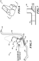
FIGURE 5 , in various embodiments, the illustrativefirst duct sections 94 may include anexpandable base section 106, adiverter 96, and a vent section having an expandable and/or flexible firstvertical section 102, aseat base outlet 98, an expandable and/or flexible secondvertical section 104, and a seat backoutlet 100. Thebase section 106 is coupled at a distal end to a proximal end of thediverter 96 and to thesecond duct section 82. As theseat 80 and/or theseat base 70 is moved either manually or by seat motors proximally and distally within thecabin 42, thebase section 106 expands or compresses thereby maintaining the connections between thesecond duct section 82 and thediverter 96. - In various embodiments, still referring to
FIGURE 5 , thediverter 96 includes an aft port that connects to a proximal end of thethird duct section 88. Thediverter 96 also includes a vertical port configured to attach to a bottom of the firstvertical section 102. Theseat base outlet 98 extends from a top end of the firstvertical section 102. The secondvertical section 104 extends vertically from the firstvertical section 102 and is attached to the seat backoutlet 100. The firstvertical section 102 and the secondvertical section 104 flex/expand as theseat section 86 and theseatback section 84 are tilted, either manually or via seat motors. - As shown in
FIGURE 7 , in various embodiments thediverter 96 includes a hinged flapper valve (flap) 110 that is rotatably attached to an interior wall of thediverter 96. The hinged flapper valve 110 may be positioned to direct air coming from an inlet side of thediverter 96 to pass only through a vertical outlet side or a distal outlet end, or simultaneously through both the vertical outlet side and the distal outlet end. The hinged flapper valve 110 may be attached to adiverter motor 112 configured to receive instructions from thecontroller 60 or power from a switch controlled by thecontroller 60 or the interface device 62. Thediverter motor 112 may be an electrical servomotor or comparable device. Thediverter motor 112 may be located on the outside of thediverter 96 with a shaft extending into thediverter 96 to make rotary contact with the flapper valve 110. The hinged flapper valve 110 may also be attached to a manual level located external to thediverter 96 that is easily accessible to an operator of vehicle 30 while sitting in theseat 80. Thediverter 96 may include other types of diverter valves, such as, without limitation, rotary vane valves and the like. Diverters are well known in the art and no further explanation is necessary for a person of skill in the art to understand disclosed subject matter. - In various embodiments, a
fan 64 is located within thesecond duct section 82, thebase section 106, thediverter 96, or thethird duct section 88. Thefan 64 receives power via a switch controlled by thecontroller 60 or the interface device 62. - As shown in
FIGURES 8 and 9 , in various embodiments, theexhaust vent 90 is rotatably attached to a distal end of thethird duct section 88. Theexhaust vent 90 may be mounted at a pivot point, such as, without limitation, a pivot pin or hinge, to thethird duct section 88. Theexhaust vent 90 may also include rotatable vertical and/or horizontal louvers. The louvers may include devices for manually operating the louvers. Theexhaust vent 90 may also include a motor(s) 92 that is attached to the louvers. The motor(s) 92 may connect between thethird duct section 88 and theexhaust vent 90 thereby causing theexhaust vent 90 to rotate about the pivot point for directing air flow coming out of theexhaust vent 90. The motor(s) 92 may be controlled by thecontroller 60, by a switch controlled by thecontroller 60, and/or the interface device 62. The motor(s) 92 may be an electrical servomotor or comparable device. - In various embodiments, the
exhaust vent 90 may direct air to thecargo bay 44 upon opening of a door located between thecabin 42 and thecargo bay 44. The door and theexhaust vent 90 may include mechanical, electromechanical, or magnetic devices that cause theexhaust vent 90 to rotate from directing air into thecabin 42 to directing air into thecargo bay 44 or cause theexhaust vent 90 to open or close depending upon the position of the door. - In various embodiments, referring back to
FIGURES 3 and 4 , anadditional vent 72 is located on a vertical section of thethird duct section 88. Theadditional vent 72 may be directed at a passenger area/seat located in thecabin 42. Theadditional vent 72 may include louvers that are directed at the passenger area or includes louvers that may be manually or automatically controlled to direct air at the passenger area. In various embodiments, theadditional vent 72 may include a vent motor(s), similar to the vent motor(s) 92, for controlling operation of the louvers of theadditional vent 72. The louvers may include devices for manually operating the louvers. The louvers of theadditional vent 72 may be positioned to block airflow, to allow uninhibited airflow, and to allow airflow at any angle from the uninhibited airflow. The vent motor(s) for theadditional vent 72 may be controlled by thecontroller 60 and/or the interface device 62, which may include an OBS located in a passenger seat. - In various embodiments, a passenger seat may include all the components described above for the
seat 80. The venting components of the passenger seat may be controlled simultaneously with the venting components ofseat 80 or may be controlled separate from the venting components ofseat 80. Thecontroller 60 may control airflow to a single bypass that leads to both thedriver seat 80 and the passenger seat or to separate venting components for thedriver seat 80 and the passenger seat. - In various embodiments, the passenger seat may include an ODS for sending seat occupancy detection information to the
controller 60 or directly to a fan, similar to the fan 64), vent motor(s), similar to the vent motor(s) 92, and/or a diverter motor, similar to thediverter motor 112, in the form of an activation signal(s). - Those skilled in the art will recognize that at least a portion of the
controller 60, the interface device 62, components, devices and/or processes described herein can be integrated into a data processing system. Those having skill in the art will recognize that a data processing system generally includes one or more of a system unit housing, a video display device, memory such as volatile or non-volatile memory, processors such as microprocessors or digital signal processors, computational entities such as operating systems, drivers, graphical user interfaces, and application programs, one or more interactive devices (e.g., a touch pad, a touch screen, etc.), and/or control systems including feedback loops and control motors (e.g., feedback for sensing position and/or velocity; control motors for moving and/or adjusting components and/or quantities). A data processing system may be implemented utilizing suitable commercially available components, such as those typically found in data computing/communication and/or network computing/communication systems. - The term controller, as used in the foregoing/following disclosure, may refer to a collection of one or more components that are arranged in a particular manner, or a collection of one or more general-purpose components that may be configured to operate in a particular manner at one or more particular points in time, and/or also configured to operate in one or more further manners at one or more further times. For example, the same hardware, or same portions of hardware, may be configured/reconfigured in sequential/parallel time(s) as a first type of controller (e.g., at a first time), as a second type of controller (e.g., at a second time, which may in some instances coincide with, overlap, or follow a first time), and/or as a third type of controller (e.g., at a third time which may, in some instances, coincide with, overlap, or follow a first time and/or a second time), etc. Reconfigurable and/or controllable components (e.g., general purpose processors, digital signal processors, field programmable gate arrays, etc.) are capable of being configured as a first controller that has a first purpose, then a second controller that has a second purpose and then, a third controller that has a third purpose, and so on. The transition of a reconfigurable and/or controllable component may occur in as little as a few nanoseconds, or may occur over a period of minutes, hours, or days.
- In some such examples, at the time the controller is configured to carry out the second purpose, the controller may no longer be capable of carrying out that first purpose until it is reconfigured. A controller may switch between configurations as different components/modules in as little as a few nanoseconds. A controller may reconfigure on-the-fly, e.g., the reconfiguration of a controller from a first controller into a second controller may occur just as the second controller is needed. A controller may reconfigure in stages, e.g., portions of a first controller that are no longer needed may reconfigure into the second controller even before the first controller has finished its operation. Such reconfigurations may occur automatically, or may occur through prompting by an external source, whether that source is another component, an instruction, a signal, a condition, an external stimulus, or similar.
- For example, a central processing unit or the like of a controller may, at various times, operate as a component/module for displaying graphics on a screen, a component/module for writing data to a storage medium, a component/module for receiving user input, and a component/module for multiplying two large prime numbers, by configuring its logical gates in accordance with its instructions. Such reconfiguration may be invisible to the naked eye, and in some embodiments may include activation, deactivation, and/or re-routing of various portions of the component, e.g., switches, logic gates, inputs, and/or outputs. Thus, in the examples found in the foregoing/following disclosure, if an example includes or recites multiple components/modules, the example includes the possibility that the same hardware may implement more than one of the recited components/modules, either contemporaneously or at discrete times or timings. The implementation of multiple components/modules, whether using more components/modules, fewer components/modules, or the same number of components/modules as the number of components/modules, is merely an implementation choice and does not generally affect the operation of the components/modules themselves. Accordingly, it should be understood that any recitation of multiple discrete components/modules in this disclosure includes implementations of those components/modules as any number of underlying components/modules, including, but not limited to, a single component/module that reconfigures itself over time to carry out the functions of multiple components/modules, and/or multiple components/modules that similarly reconfigure, and/or special purpose reconfigurable components/modules.
- In some instances, one or more components may be referred to herein as "configured to," "configured by," "configurable to," "operable/operative to," "adapted/adaptable," "able to," "conformable/conformed to," etc. Those skilled in the art will recognize that such terms (for example "configured to") generally encompass active-state components and/or inactive-state components and/or standby-state components, unless context requires otherwise.
- While particular aspects of the present subject matter described herein have been shown and described, it will be apparent to those skilled in the art that, based upon the teachings herein, changes and modifications may be made without departing from the subject matter described herein and its broader aspects and, therefore, the appended claims are to encompass within their scope all such changes and modifications as are within the true spirit and scope of the subject matter described herein. It will be understood by those within the art that, in general, terms used herein, and especially in the appended claims (for example, bodies of the appended claims) are generally intended as "open" terms (for example, the term "including" should be interpreted as "including but not limited to," the term "having" should be interpreted as "having at least," the term "includes" should be interpreted as "includes but is not limited to," etc.). It will be further understood by those within the art that if a specific number of an introduced claim recitation is intended, such an intent will be explicitly recited in the claim, and in the absence of such recitation no such intent is present. For example, as an aid to understanding, the following appended claims may contain usage of the introductory phrases "at least one" and "one or more" to introduce claim recitations. However, the use of such phrases should not be construed to imply that the introduction of a claim recitation by the indefinite articles "a" or "an" limits any particular claim containing such introduced claim recitation to claims containing only one such recitation, even when the same claim includes the introductory phrases "one or more" or "at least one" and indefinite articles such as "a" or "an" (for example, "a" and/or "an" should typically be interpreted to mean "at least one" or "one or more"); the same holds true for the use of definite articles used to introduce claim recitations. In addition, even if a specific number of an introduced claim recitation is explicitly recited, those skilled in the art will recognize that such recitation should typically be interpreted to mean at least the recited number (for example, the bare recitation of "two recitations," without other modifiers, typically means at least two recitations, or two or more recitations). Furthermore, in those instances where a convention analogous to "at least one of A, B, and C, etc." is used, in general such a construction is intended in the sense one having skill in the art would understand the convention (for example, " a system having at least one of A, B, and C" would include but not be limited to systems that have A alone, B alone, C alone, A and B together, A and C together, B and C together, and/or A, B, and C together, etc.). It will be further understood by those within the art that typically a disjunctive word and/or phrase presenting two or more alternative terms, whether in the description, claims, or drawings, should be understood to contemplate the possibilities of including one of the terms, either of the terms, or both terms unless context dictates otherwise. For example, the phrase "A or B" will be typically understood to include the possibilities of "A" or "B" or "A and B."
- The foregoing detailed description has set forth various embodiments of the devices and/or processes via the use of block diagrams, flowcharts, and/or examples. Insofar as such block diagrams, flowcharts, and/or examples contain one or more functions and/or operations, it will be understood by those within the art that each function and/or operation within such block diagrams, flowcharts, or examples can be implemented, individually and/or collectively, by a wide range of hardware, software (e.g., a high-level computer program serving as a hardware specification), firmware, or virtually any to patentable subject matter under 35 U.S.C. 101. In an embodiment, several portions of the subject matter described herein may be implemented via Application Specific Integrated Circuits (ASICs), Field Programmable Gate Arrays (FPGAs), digital signal processors (DSPs), or other integrated formats. However, those skilled in the art will recognize that some aspects of the embodiments disclosed herein, in whole or in part, can be equivalently implemented in integrated circuits, as one or more computer programs running on one or more computers (e.g., as one or more programs running on one or more computer systems), as one or more programs running on one or more processors (e.g., as one or more programs running on one or more microprocessors), as firmware, or as virtually any combination thereof, limited to patentable subject matter under 35 U.S.C. 101, and that designing the circuitry and/or writing the code for the software (e.g., a high-level computer program serving as a hardware specification) and or firmware would be well within the skill of one of skill in the art in light of this disclosure. In addition, those skilled in the art will appreciate that the mechanisms of the subject matter described herein are capable of being distributed as a program product in a variety of forms, and that an illustrative embodiment of the subject matter described herein applies regardless of the particular type of signal bearing medium used to actually carry out the distribution. Examples of a signal bearing medium include, but are not limited to, the following: a recordable type medium such as a floppy disk, a hard disk drive, a Compact Disc (CD), a Digital Video Disk (DVD), a digital tape, a computer memory, etc.; and a transmission type medium such as a digital and/or an analog communication medium (e.g., a fiber optic cable, a waveguide, a wired communications link, a wireless communication link (e.g., transmitter, receiver, transmission logic, reception logic, etc.), etc.).
- With respect to the appended claims, those skilled in the art will appreciate that recited operations therein may generally be performed in any order. Also, although various operational flows are presented in a sequence(s), it should be understood that the various operations may be performed in other orders than those which are illustrated or may be performed concurrently. Examples of such alternate orderings may include overlapping, interleaved, interrupted, reordered, incremental, preparatory, supplemental, simultaneous, reverse, or other variant orderings, unless context dictates otherwise. Furthermore, terms like "responsive to," "related to," or other past-tense adjectives are generally not intended to exclude such variants, unless context dictates otherwise.
- While the disclosed subject matter has been described in terms of illustrative embodiments, it will be understood by those skilled in the art that various modifications can be made thereto without departing from the scope of the claimed subject matter as set forth in the claims.
Claims (14)
- A device comprising:a seat including a first section of duct having a first end;a second section of duct configured to connect at a first end to an air supply source and at a second end to the first end of the first section of duct; anda third section of duct configured to connect to the first section of duct, wherein the third section of duct includes a vent configured to direct air received from the air supply source in a direction aft of the seat.
- The device of Claim 1, wherein the vent is configured to direct air into a cargo bay.
- The device of Claim 1 or 2, wherein the vent includes a swivel device configured to cause the vent to be positioned in multiple directions.
- The device of Claim 3, wherein the swivel device includes a motor configured to control position of the vent responsive to a signal received from a device chosen from a controller and an interface device.
- The device of any preceding Claim, wherein the first section of duct includes:a vent section disposed in a location of the seat chosen from a back section and a seat section; anda diverter configured to cause air received from the air supply source to be diverted into one of the vent section and the third section of duct.
- The device of Claim 5, wherein the diverter includes:a hinged flap; anda motor configured to control position of the hinged flap responsive to a signal received from a device chosen from a controller and an interface device.
- The device of any preceding Claim, further comprising a fan disposed at a location chosen from the first section of duct and the third section of duct, wherein the fan is configured to cause movement of air responsive to a signal received from a device chosen from a controller and an interface device.
- A system comprising:an interface device configured to receive instructions from a user;an air supply unit;a controller configured to command the air supply unit to output air at a particular temperature responsive to the received instructions; anda device according to any preceding claim.
- A vehicle comprising:a cabin;a cargo bay disposed aft of the cabin;an interface device configured to receive instructions from a user;an air supply unit;a controller configured to command the air supply unit to output air at a particular temperature responsive to the received instructions;a seat disposed in the cabin, wherein the seat includes a first section of duct having a first end;a second section of duct configured to connect at a first end to an air supply source and at a second end to the first end of the first section of duct; anda third section of duct configured to connect to the first section of duct, wherein the third section of duct includes a vent configured to direct air received from the air supply source in a direction aft of the seat.
- The vehicle of Claim 9, wherein the vent is configured to direct air into the cargo bay.
- The vehicle of Claim 9 or 10, wherein the vent includes a motor configured to control position of the vent responsive to a signal received from a device chosen from a controller and the interface device.
- The vehicle of any one of Claims 9 to 11, wherein the first section of duct includes:a vent section disposed in a location of the seat chosen from a back section and a seat section; anda diverter configured to cause air received from the air supply source to be diverted into one of the vent section and the third section of duct.
- The vehicle of any one of Claims 9 to 12, wherein the diverter includes:a hinged flap; anda motor configured to control position of the diverter responsive to a signal received from a device chosen from a controller and an interface device.
- The vehicle of any one of Claims 9 to 13, further comprising a fan disposed at a location chosen from the first section of duct and the third section of duct, wherein the fan is configured to cause movement of air responsive to a signal received from a device chosen from a controller and an interface device.
Applications Claiming Priority (1)
| Application Number | Priority Date | Filing Date | Title |
|---|---|---|---|
| US17/696,938 US12005760B2 (en) | 2022-03-17 | 2022-03-17 | Devices, systems, and vehicles for providing ventilation |
Publications (1)
| Publication Number | Publication Date |
|---|---|
| EP4245580A1 true EP4245580A1 (en) | 2023-09-20 |
Family
ID=84329879
Family Applications (1)
| Application Number | Title | Priority Date | Filing Date |
|---|---|---|---|
| EP22205037.9A Pending EP4245580A1 (en) | 2022-03-17 | 2022-11-02 | Devices, systems, and vehicles for providing ventilation |
Country Status (3)
| Country | Link |
|---|---|
| US (1) | US12005760B2 (en) |
| EP (1) | EP4245580A1 (en) |
| CN (1) | CN116767049A (en) |
Families Citing this family (1)
| Publication number | Priority date | Publication date | Assignee | Title |
|---|---|---|---|---|
| CN120116829A (en) * | 2025-04-24 | 2025-06-10 | 浙江吉利控股集团有限公司 | Seat assembly, heating method and vehicle |
Citations (3)
| Publication number | Priority date | Publication date | Assignee | Title |
|---|---|---|---|---|
| DE19737636A1 (en) * | 1997-08-28 | 1999-03-11 | Aisin Seiki | Climate-controlled for vehicle seats or bed |
| JP2007186152A (en) * | 2006-01-16 | 2007-07-26 | Denso Corp | Vehicle seat air conditioner |
| US20180117987A1 (en) * | 2015-04-02 | 2018-05-03 | Denso Corporation | Air conditioning unit for vehicle seat |
Family Cites Families (8)
| Publication number | Priority date | Publication date | Assignee | Title |
|---|---|---|---|---|
| KR19980018296U (en) * | 1996-09-25 | 1998-07-06 | 임경춘 | Room temperature reduction device in automobile |
| US6105667A (en) * | 1998-03-12 | 2000-08-22 | Denso Corporation | Air conditioning apparatus for vehicle seat |
| US6902473B1 (en) * | 2004-01-06 | 2005-06-07 | Kenneth D. Goobeck | Vehicle ventilation conduit system |
| EP1768890B1 (en) * | 2004-06-09 | 2008-06-18 | Wrightbus Limited | Improvements relating to passenger service vehicles |
| US7909379B2 (en) * | 2008-09-18 | 2011-03-22 | Global Ip Holdings, Llc | Kit and bulkhead assembly for cargo vehicles |
| US20140196866A1 (en) * | 2013-01-16 | 2014-07-17 | GM Global Technology Operations LLC | Return air ducts for vehicles |
| US20150140915A1 (en) * | 2013-11-19 | 2015-05-21 | Atieva, Inc. | Vehicle Seat Ventilation System |
| US11235643B2 (en) * | 2018-11-27 | 2022-02-01 | Scott Bradley Baker | Air vent assembly and control system |
-
2022
- 2022-03-17 US US17/696,938 patent/US12005760B2/en active Active
- 2022-11-02 EP EP22205037.9A patent/EP4245580A1/en active Pending
- 2022-11-17 CN CN202211437719.2A patent/CN116767049A/en active Pending
Patent Citations (3)
| Publication number | Priority date | Publication date | Assignee | Title |
|---|---|---|---|---|
| DE19737636A1 (en) * | 1997-08-28 | 1999-03-11 | Aisin Seiki | Climate-controlled for vehicle seats or bed |
| JP2007186152A (en) * | 2006-01-16 | 2007-07-26 | Denso Corp | Vehicle seat air conditioner |
| US20180117987A1 (en) * | 2015-04-02 | 2018-05-03 | Denso Corporation | Air conditioning unit for vehicle seat |
Also Published As
| Publication number | Publication date |
|---|---|
| CN116767049A (en) | 2023-09-19 |
| US12005760B2 (en) | 2024-06-11 |
| US20230294479A1 (en) | 2023-09-21 |
Similar Documents
| Publication | Publication Date | Title |
|---|---|---|
| US20220258565A1 (en) | Systems and methods for controlling vents of a vehicle | |
| CN101234590B (en) | Method for vehicle environmental management | |
| US8694205B1 (en) | Multi-zone demist strategy | |
| EP4245580A1 (en) | Devices, systems, and vehicles for providing ventilation | |
| CN105711374A (en) | Air vent assembly with integral air vent and control head | |
| US20230060635A1 (en) | Vehicle seat with airflow outlets | |
| WO1994006070A1 (en) | Installer climate control system | |
| US20150224853A1 (en) | Deployable vent for automotive ventilation system | |
| US5934988A (en) | Method and apparatus for motor vehicle heating and air-conditioning | |
| US20230294480A1 (en) | Devices, systems, and vehicles for providing heating, ventilation, and air conditioning (hvac) functions | |
| EP4124480B1 (en) | Heating, ventilation, and air conditioning case with multi-position door for case recirculation | |
| JPH0725224A (en) | Vehicle air conditioner | |
| US12397615B2 (en) | Air-conditioning system for mobility vehicles | |
| CN111703272B (en) | Vehicle rear row air conditioner device and vehicle | |
| US20230049777A1 (en) | Devices, systems, vehicles, and methods for cooling electronics | |
| US12515497B2 (en) | Integrated converging ventilization system | |
| US12011971B2 (en) | Automatic air intake sealing | |
| US20240166023A1 (en) | Air curtain for dispelling particulates from a vehicle | |
| US11958339B2 (en) | Concealed air vent apparatus in vehicle and a method thereof | |
| CN109577785A (en) | Vehicle window driving device, vehicle control system, vehicle and control method for vehicle | |
| JP2019108031A (en) | Air conditioner for vehicle | |
| JP2551111Y2 (en) | Automotive air conditioners | |
| JPH08332833A (en) | Air conditioning system for automobile | |
| JP3591750B2 (en) | Door control device for vehicle air conditioner system | |
| JPH0341923Y2 (en) |
Legal Events
| Date | Code | Title | Description |
|---|---|---|---|
| PUAI | Public reference made under article 153(3) epc to a published international application that has entered the european phase |
Free format text: ORIGINAL CODE: 0009012 |
|
| STAA | Information on the status of an ep patent application or granted ep patent |
Free format text: STATUS: REQUEST FOR EXAMINATION WAS MADE |
|
| 17P | Request for examination filed |
Effective date: 20221102 |
|
| AK | Designated contracting states |
Kind code of ref document: A1 Designated state(s): AL AT BE BG CH CY CZ DE DK EE ES FI FR GB GR HR HU IE IS IT LI LT LU LV MC ME MK MT NL NO PL PT RO RS SE SI SK SM TR |
|
| STAA | Information on the status of an ep patent application or granted ep patent |
Free format text: STATUS: EXAMINATION IS IN PROGRESS |
|
| 17Q | First examination report despatched |
Effective date: 20250408 |
|
| RAP3 | Party data changed (applicant data changed or rights of an application transferred) |
Owner name: RIVIAN IP HOLDINGS, LLC |