EP4245470A1 - Wearable suit - Google Patents
Wearable suit Download PDFInfo
- Publication number
- EP4245470A1 EP4245470A1 EP22176270.1A EP22176270A EP4245470A1 EP 4245470 A1 EP4245470 A1 EP 4245470A1 EP 22176270 A EP22176270 A EP 22176270A EP 4245470 A1 EP4245470 A1 EP 4245470A1
- Authority
- EP
- European Patent Office
- Prior art keywords
- unit
- muscular strength
- user
- wearable suit
- guiding member
- Prior art date
- Legal status (The legal status is an assumption and is not a legal conclusion. Google has not performed a legal analysis and makes no representation as to the accuracy of the status listed.)
- Granted
Links
Images







Classifications
-
- A—HUMAN NECESSITIES
- A61—MEDICAL OR VETERINARY SCIENCE; HYGIENE
- A61H—PHYSICAL THERAPY APPARATUS, e.g. DEVICES FOR LOCATING OR STIMULATING REFLEX POINTS IN THE BODY; ARTIFICIAL RESPIRATION; MASSAGE; BATHING DEVICES FOR SPECIAL THERAPEUTIC OR HYGIENIC PURPOSES OR SPECIFIC PARTS OF THE BODY
- A61H1/00—Apparatus for passive exercising; Vibrating apparatus; Chiropractic devices, e.g. body impacting devices, external devices for briefly extending or aligning unbroken bones
- A61H1/02—Stretching or bending or torsioning apparatus for exercising
- A61H1/0274—Stretching or bending or torsioning apparatus for exercising for the upper limbs
-
- B—PERFORMING OPERATIONS; TRANSPORTING
- B25—HAND TOOLS; PORTABLE POWER-DRIVEN TOOLS; MANIPULATORS
- B25J—MANIPULATORS; CHAMBERS PROVIDED WITH MANIPULATION DEVICES
- B25J9/00—Program-controlled manipulators
- B25J9/0006—Exoskeletons, i.e. resembling a human figure
-
- B—PERFORMING OPERATIONS; TRANSPORTING
- B25—HAND TOOLS; PORTABLE POWER-DRIVEN TOOLS; MANIPULATORS
- B25J—MANIPULATORS; CHAMBERS PROVIDED WITH MANIPULATION DEVICES
- B25J9/00—Program-controlled manipulators
- B25J9/10—Program-controlled manipulators characterised by positioning means for manipulator elements
- B25J9/1085—Program-controlled manipulators characterised by positioning means for manipulator elements positioning by means of shape-memory materials
-
- A—HUMAN NECESSITIES
- A61—MEDICAL OR VETERINARY SCIENCE; HYGIENE
- A61H—PHYSICAL THERAPY APPARATUS, e.g. DEVICES FOR LOCATING OR STIMULATING REFLEX POINTS IN THE BODY; ARTIFICIAL RESPIRATION; MASSAGE; BATHING DEVICES FOR SPECIAL THERAPEUTIC OR HYGIENIC PURPOSES OR SPECIFIC PARTS OF THE BODY
- A61H2201/00—Characteristics of apparatus not provided for in the preceding codes
- A61H2201/12—Driving means
- A61H2201/1207—Driving means with electric or magnetic drive
-
- A—HUMAN NECESSITIES
- A61—MEDICAL OR VETERINARY SCIENCE; HYGIENE
- A61H—PHYSICAL THERAPY APPARATUS, e.g. DEVICES FOR LOCATING OR STIMULATING REFLEX POINTS IN THE BODY; ARTIFICIAL RESPIRATION; MASSAGE; BATHING DEVICES FOR SPECIAL THERAPEUTIC OR HYGIENIC PURPOSES OR SPECIFIC PARTS OF THE BODY
- A61H2201/00—Characteristics of apparatus not provided for in the preceding codes
- A61H2201/16—Physical interface with patient
- A61H2201/1602—Physical interface with patient kind of interface, e.g. head rest, knee support or lumbar support
- A61H2201/1614—Shoulder, e.g. for neck stretching
-
- A—HUMAN NECESSITIES
- A61—MEDICAL OR VETERINARY SCIENCE; HYGIENE
- A61H—PHYSICAL THERAPY APPARATUS, e.g. DEVICES FOR LOCATING OR STIMULATING REFLEX POINTS IN THE BODY; ARTIFICIAL RESPIRATION; MASSAGE; BATHING DEVICES FOR SPECIAL THERAPEUTIC OR HYGIENIC PURPOSES OR SPECIFIC PARTS OF THE BODY
- A61H2201/00—Characteristics of apparatus not provided for in the preceding codes
- A61H2201/16—Physical interface with patient
- A61H2201/1602—Physical interface with patient kind of interface, e.g. head rest, knee support or lumbar support
- A61H2201/1619—Thorax
-
- A—HUMAN NECESSITIES
- A61—MEDICAL OR VETERINARY SCIENCE; HYGIENE
- A61H—PHYSICAL THERAPY APPARATUS, e.g. DEVICES FOR LOCATING OR STIMULATING REFLEX POINTS IN THE BODY; ARTIFICIAL RESPIRATION; MASSAGE; BATHING DEVICES FOR SPECIAL THERAPEUTIC OR HYGIENIC PURPOSES OR SPECIFIC PARTS OF THE BODY
- A61H2201/00—Characteristics of apparatus not provided for in the preceding codes
- A61H2201/16—Physical interface with patient
- A61H2201/1602—Physical interface with patient kind of interface, e.g. head rest, knee support or lumbar support
- A61H2201/164—Feet or leg, e.g. pedal
-
- A—HUMAN NECESSITIES
- A61—MEDICAL OR VETERINARY SCIENCE; HYGIENE
- A61H—PHYSICAL THERAPY APPARATUS, e.g. DEVICES FOR LOCATING OR STIMULATING REFLEX POINTS IN THE BODY; ARTIFICIAL RESPIRATION; MASSAGE; BATHING DEVICES FOR SPECIAL THERAPEUTIC OR HYGIENIC PURPOSES OR SPECIFIC PARTS OF THE BODY
- A61H2201/00—Characteristics of apparatus not provided for in the preceding codes
- A61H2201/16—Physical interface with patient
- A61H2201/1602—Physical interface with patient kind of interface, e.g. head rest, knee support or lumbar support
- A61H2201/165—Wearable interfaces
Definitions
- the present disclosure relates to a wearable suit.
- a wearable robot and a wearable suit refer to a type of robot that is worn on a human body.
- a user is directly in charge of posture control, context-awareness, and motion signal generation, which artificial intelligence of the robot is responsible for, and the wearable suit responds to various situations to assist muscular strength and mobility of the user or the like.
- the wearable suits are being used in various fields such as military use, disaster relief, industrial work, rehabilitation treatment, and daily life assistance.
- the wearable suit can increase a work performance time and a work range of the user by assisting physical ability of the user in environments such as disaster sites and mountainous terrain.
- the wearable suit may be used for work and rehabilitation treatment by assisting the muscular strength and physical defects of the user in daily life.
- the wearable suit may be divided into a passive type suit and an active type suit according to a power implementation method.
- the passive type means a method using a preset force such as a spring and an elastic band
- the active type means a method using a variable force such as a motor and hydraulic pressure.
- a wearable suit configured to assist muscular strength of a user
- the wearable suit comprising: a body unit; a fixing unit configured to fix the body unit to an upper body of the user; an arm coupling unit coupled to at least a portion of an arm of the user; and an arm connecting unit configured to connect the body unit and the arm coupling unit to each other, wherein the body unit comprises a housing defining an accommodating space therein; and a muscular strength assistance unit disposed inside the housing and comprising at least a portion comprised of a shape memory alloy material.
- the wearable suit may include a guiding unit configured to guide a position of the arm connecting unit.
- the guiding unit may include at least one guiding member to accommodate at least a portion of the arm connecting unit.
- the at least one guiding member may include a first guiding member including one side connected to the housing and disposed such that at least a portion of the arm connecting unit is inserted.
- one portion of the first guiding member may extend in a direction toward an upper side of the user from the housing, and a remaining portion of the first guiding member may extend in a direction from the one portion of the first guiding member toward a front of the user.
- the at least one guiding member may include a second guiding member including at least a portion coupled to the fixing unit and disposed such that at least a portion of the arm connecting unit is inserted.
- the second guiding member may be integral with at least a portion of the fixing unit.
- At least a portion of the at least one guiding member may be curved.
- the wearable suit may include: a leg coupling unit coupled to at least a portion of a leg of the user; and a leg connecting unit configured to connect the body unit and the leg coupling unit to each other.
- the fixing unit may include one or more of a shoulder belt, a chest belt, a waist belt, and a leg belt.
- the fixing unit may be vest shaped.
- the muscular strength assistance unit may include at least one muscular strength assistance spring, and the at least one muscular strength assistance spring may be formed of a shape memory alloy material.
- the muscular strength assistance unit may include two or more muscular strength assistance springs and the muscular strength assistant springs may be disposed in at least one form of series and parallel.
- the wearable suit may include a power supply unit configured to supply power to the muscular strength assistance unit, and at least a portion of the muscular strength assistance unit may be expanded and contracted based on the power.
- a wearable suit uses a muscular strength assistance unit formed of a shape memory alloy material to assist muscular strength of a user, thereby simplifying a structure, reducing weight, and removing noise caused by driving of a motor.
- various terms such as first, second, A, B, (a), (b), etc. are used solely to differentiate one component from the other but not to imply or suggest the substances, order, or sequence of the components.
- a part 'includes' or 'comprises' a component the part is meant to further include other components, not to exclude thereof unless specifically stated to the contrary.
- the terms such as 'unit', 'module', and the like refer to one or more units for processing at least one function or operation, which may be implemented by hardware, software, or a combination thereof.
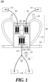
- FIG. 1 is a view illustrating a configuration of a wearable suit according to one embodiment of the present disclosure.
- FIG. 2 is a view illustrating a state of a user wearing the wearable suit according to one embodiment of the present disclosure.
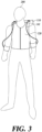
- FIG. 3 is a view illustrating a fixing unit according to another embodiment of the present disclosure.
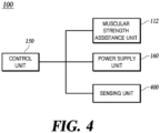
- FIG. 4 is a block diagram of the wearable suit according to one embodiment of the present disclosure.
- a wearable suit 100 may include a body unit 110, a fixing unit 120, a coupling unit 130, a connecting unit 140, a control unit 150, and a power supply unit 160.
- the body unit 110 may include a housing 111 and a muscular strength assistance unit 112.
- the muscular strength assistance unit 112 may include a muscular strength assistance spring 112a, a terminal 112b, and a supporting member 112c.
- the fixing unit 120 may include a shoulder belt 121, a chest belt 122, and a waist belt 123.
- the coupling unit 130 may include an arm coupling unit 131 and a leg coupling unit 132.
- the connecting unit 140 may include an arm connecting unit 141 and a leg connecting unit 142.
- the body unit 110 is disposed in at least a portion of an upper body of a user 200.
- the body unit 110 may be disposed at the rear of the upper body of the user 200. At least a portion of the body unit 110 is formed of a shape memory alloy material.
- the body unit 110 may be connected to at least a portion of the fixing unit 120.
- the body unit 110 may be connected to the shoulder belt 121 and the waist belt 123.
- the body unit 110 is connected to the connecting unit 140.
- the body unit 110 is connected to the coupling unit 130 using the connecting unit 140.
- the control unit 150 may control the body unit 110 so that the body unit 110 is activated or deactivated.
- the housing 111 is disposed in at least a portion of the upper body of the user 200.
- the housing 111 may include an accommodation space therein.
- the control unit 150, the power supply unit 160, a guiding unit (500, 600, 700, refer to FIGS. 5 to 7 ), and the connecting unit 140 may be disposed.
- the housing 111 and the shoulder belt 121 may be formed in a backpack shape.
- the muscular strength assistance unit 112 is configured to assist the muscular strength of the user 200.
- the muscular strength assistance unit 112 may be disposed inside the housing 111. At least a portion of the muscular strength assistance unit 112 is formed of a shape memory alloy material. At least a portion of the muscular strength assistance unit 112 may be contracted and expanded. Power may be applied to the muscular strength assistance unit 112 by the power supply unit 160. At least a portion of the muscular strength assistance unit 112 is connected to the connecting unit 140.
- the muscular strength assistance unit 112 may be connected to the coupling unit 130 using a connecting unit 140. There may be a plurality of muscular strength assistance units 112.
- the muscular strength assistance unit 112 may be controlled by a control unit 150.
- the muscular strength assistance spring 112a is formed of a shape memory alloy material.
- the muscular strength assistance spring 112a is configured to be contractible and expandable.
- the muscular strength assistance spring 112a may be disposed inside the housing 111.
- the muscular strength assistance spring 112a may be electrically connected to the terminal 112b.
- the muscular strength assistance spring 112a may be connected to the supporting member 112c. As the muscular strength assistance spring 112a is contracted or expanded, the terminal 112b and the supporting member 112c may move. In this way, compared to a case of driving only the motor, when the muscular strength assistance spring 112a is used as a driving source of the wearable suit 100, the weight of the wearable suit 100 can be reduced, and noise caused by the driving of the motor can be reduced.
- the muscular strength assistance spring 112a may be contracted and expanded using the power supplied from the power supply unit 160. Heat is generated by the electric power applied to the muscular strength assistance spring 112a and electrical resistance of the muscular strength assistance spring 112a. As the temperature of the muscular strength assistance spring 112a increases, the muscular strength assistance spring 112a is contracted. As the electric power supplied to the muscular strength assistance spring 112a is cut off, the muscular strength assistance spring 112a may be cooled.
- the plurality of muscular strength assistance springs 112a may be disposed in series and/or parallel to each other. In this case, the plurality of muscular strength assistance springs 112a may be disposed in an appropriate shape in consideration of the resistance of the muscular strength assistance spring 112a and power supplied from the power supply unit 160.
- the terminal 112b may be formed on the supporting member 112c.
- the terminal 112b may be electrically connected to the muscular strength assistance spring 112a.
- the terminal 112b may be electrically connected to the power supply unit 160.
- the terminal 112b may transmit power supplied from the power supply unit 160 to the muscular strength assistance spring 112a.
- the terminal 112b may be connected to the muscular strength assistance spring 112a and/or the supporting member 112c. As the muscular strength assistance spring 112a is contracted or expanded, the terminal 112b may move together with the supporting member 112c.
- the terminal 112b may be disposed inside the housing 111.
- the supporting member 112c is connected to the muscular strength assistance spring 112a and/or the terminal 112b to support the muscular strength assistance spring 112a and/or the terminal 112b.
- the supporting member 112c may be disposed on both sides of the muscular strength assistance spring 112a.
- the supporting member 112c may be disposed inside the housing 111.
- the terminal 112b may be formed on the supporting member 112c.
- There may be a plurality of supporting members 112c. Some of the plurality of supporting members 112c may be connected to the connecting unit 140.
- the supporting member 112c connected to the connecting unit 140 may move as the muscular strength assistance spring 112a is contracted or expanded to assist the muscular strength of the user 200.
- Other supporting members 112c of the plurality of supporting members 112c may be fixed to the inside of the housing 111.
- at least some of the plurality of supporting members 112c connected to the connecting unit 140 may be movably installed with respect to the housing 111, and at least some not connected to the connecting unit 140 may be installed to be fixed to the housing 111.
- the fixing unit 120 fixes the body unit 110 to the upper body of the user 200. At least a portion of the fixing unit 120 may be connected to the housing 111.
- the fixing unit 120 may include one or more of the shoulder belt 121, the chest belt 122, the waist belt 123, and the leg belt.
- the shoulder belt 121 fixes the body unit 1 10 to the upper body of the user 200.
- the shoulder belt 121 may be configured to surround the shoulder of the user 200. Both sides of the shoulder belt 121 may be connected to the housing 111. At least a portion of the chest belt 122 may be connected to the shoulder belt 121.
- the chest belt 122 fixes the body unit 110 to the upper body of the user 200.
- the chest belt 122 may be configured to surround the chest of the user 200. At least a portion of the chest belt 122 may be connected to the shoulder belt 121. A middle portion of the chest belt 122 may be formed in a structure capable of being coupled and detached.
- the waist belt 123 fixes the body unit 110 to the upper body of the user 200.
- the waist belt 123 may be configured to surround the waist of the user 200. Both sides of the waist belt 123 may be connected to the housing 111. A middle portion of the waist belt 123 may be formed in a structure that is coupled and detachable. According to the waist belt 123, it is possible to stably maintain a state in which the body unit 110 is positioned in the upper body of the user 200. Meanwhile, even when the waist belt 123 is not provided, the body unit 110 can be positioned at the upper body of the user 200 by a fixing force of the leg belt, which will be described later, or by the own weight and the shoulder belt 121 of the body unit 110.
- the leg belt may fix the body unit 110 to the upper body of the user 200.
- the leg belt fixes the body unit 110 to the upper body of the user 200.
- the leg coupling unit 132 and the leg connecting unit 142 may serve as the leg belt.
- the leg belt may be omitted.
- the fixing unit 120 may be provided in the form of a vest.
- the fixing unit 120 in the form of a vest it may be understood that two or more of the shoulder belt 121, the chest belt 122, and the waist belt 123 are integrally formed.
- the fixing unit 120 may be formed in a shape in which the left and right shoulder belts 121 are interconnected by a fastening means, for example, a zipper or a button.
- the coupling unit 130 is coupled to at least a portion of the body of the user 200.
- the coupling unit 130 may be coupled to at least a portion of the arm and/or leg of the user 200.
- the coupling unit 130 may be connected to the body unit 110 by the connecting unit 140.
- the coupling unit 130 may be connected to the muscular strength assistance unit 112 to assist the muscular strength of the user 200.
- the coupling unit 130 may be formed in a band shape.
- the arm coupling unit 131 is coupled to at least a portion of the arm of the user 200.
- the arm coupling unit 131 may be connected to the muscular strength assistance unit 112 by the arm connecting unit 141 and assist the muscular strength of the arm of the user 200.
- the leg coupling unit 132 is coupled to at least a portion of the leg of the user 200.
- the leg coupling unit 132 may be connected to the muscular strength assistance unit 112 by the leg connecting unit 142, and may assist the muscular strength of the leg and/or the waist of the user 200.
- the leg coupling unit 132 may constitute a portion of the leg belt.
- the connecting unit 140 connects the body unit 110 and the coupling unit 130 to each other.
- the connecting unit 140 connects the muscular strength assistance unit 112 and the coupling unit 130 to each other. At least a portion of the connecting unit 140 may move as the muscular strength assistance spring 112a is contracted or expanded.
- the connecting unit 140 may be formed of a non-stretchable material.
- at least a portion of the connecting unit 140 may be formed of a polyester material.
- a thickness of the connecting unit 140 may be 8 mm to 10 mm.
- At least a portion of the connecting unit 140 is inserted into the inside of the guiding member (500, 600, 700, refer to FIGS. 5 to 7 ), and thus, the position of the connecting unit 140 may be guided and/or fixed.
- the arm connecting unit 141 connects the body unit 110 and the arm coupling unit 131 to each other.
- the arm connecting unit 141 connects the muscular strength assistance unit 112 and the arm coupling unit 131 to each other. As the muscular strength assistance spring 112a is contracted or expanded, at least a portion of the arm connecting unit 141 may move to assist the muscular strength of the arm of the user 200.
- the arm coupling unit 131 and the arm connecting unit 141 may be omitted.
- the leg connecting unit 142 connects the body unit 110 and the leg coupling unit 132 to each other.
- the leg connecting unit 142 connects the muscular strength assistance unit 112 and the leg coupling unit 132 to each other.
- the muscular strength assistance spring 112a is contracted or expanded, at least a portion of the leg connecting unit 142 may move to assist the muscular strength of the leg and/or the waist of the user 200.
- the leg connecting unit 142 may constitute a portion of the leg belt.
- the leg connecting unit 142 may be formed in a "Y" shape or an "H" shape.
- the leg connecting unit 142 may be formed integrally, but is not necessarily limited thereto, and may be formed in a shape in which a plurality of components are combined according to the purpose and use.
- the leg coupling unit 132 and the leg connecting unit 142 may be omitted.
- the control unit 150 may control each configuration of the wearable suit 100.
- the control unit 150 may be disposed inside the housing 111.
- the control unit 150 may receive information acquired by a sensing unit 400.
- the control unit 150 may receive a signal related to operation or deactivation from a timer and/or a switch.
- the control unit 150 may control the power supply unit 160 based on information obtained by the sensing unit 400.
- the control unit 150 may control the body unit 110 using the power supply unit 160.
- the control unit 150 may operate the wearable suit 100 based on an operation signal transmitted from a switch or the like. In this case, the control unit 150 may operate the wearable suit 100 by controlling the power supply unit 160 to supply power from the power supply unit 160 to the muscular strength assistance unit 112.
- the control unit 150 may cancel the operation of the wearable suit 100 based on the information transmitted from a timer and/or the sensing unit 400. In this case, the control unit 150 controls the power supply unit 160 so that the power supplied from the power supply unit 160 to the muscular strength assistance unit 112 is cut off, thereby canceling the operation of the wearable suit 100.
- the control unit 150 may release the operation of the wearable suit 100 based on information transmitted from the timer.
- the control unit 150 may release the operation of the wearable suit 100 based on information on a load acting on the wearable suit 100.
- the control unit 150 may release the operation of the wearable suit 100 based on whether the load acting on the connecting unit 140 decreases and/or whether a load reduction time is equal to or longer than a preset time.
- the power supply unit 160 may be electrically connected to at least a portion of the muscular strength assistance unit 112 to supply power to the muscular strength assistance unit 112.
- the power supply unit 160 may be electrically connected to the terminal 112b.
- the power supply unit 160 may be disposed inside the housing 111. Heat is generated by the electric power supplied from the power supply unit 160 and the electrical resistance of the muscular strength assistance spring 112a, and the temperature of the muscular strength assistance spring 112a increases. Accordingly, the muscular strength assistance spring 112a is contracted and provides tension to the connecting unit 140 to assist the muscular strength of the body part of the user equipped with the coupling unit 130, that is, the arm, waist and/or leg.
- the power supply unit 160 may be controlled by the control unit 150 to supply or cut power to the muscular strength assistance unit 112.
- FIG. 5 is a view illustrating the wearable suit installed with a first guiding member according to one embodiment of the present disclosure.
- FIG. 6 is a view illustrating the wearable suit installed with a second guiding member according to one embodiment of the present disclosure.
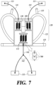
- FIG. 7 is a view illustrating the wearable suit installed with a third guiding member according to one embodiment of the present disclosure.
- the guiding unit according to one embodiment of the present disclosure will be described in detail with reference to FIGS. 5 to 7 .
- the wearable suit 100 may further include the guiding unit configured to guide the position of the connecting unit 140.
- the guiding unit allows the connecting unit 140 to move along a set path, and thus, it is possible to further improve control accuracy.
- the guiding unit may include one or more guiding members 500, 600, and 700 configured to be inserted into at least a portion of the connecting unit 140.
- the guiding members 500, 600, and 700 may include a first guiding member 500, a second guiding member 600, and a third guiding member 700.
- FIG. 5 to 7 illustrate each of the guiding members 500, 600, and 700 by way of example, but, those of ordinary skill in the art will understand that the wearable suit 100 may include two or more guiding members 500, 600, and 700 together.
- the first guiding member 500 may guide and/or fix the position of the arm connecting unit 141.
- the first guiding member 500 is configured to accommodate at least a portion of the arm connecting unit 141.
- the first guiding member 500 prevents the arm connecting unit 141 from coming into direct contact with the body of the user, and thus, it is possible to reduce the problem that the user is injured in the process of the arm connecting unit 141 moving.
- One side of the first guiding member 500 toward the upper side and/or the front of the user from the housing 111 may be connected to the housing 111.
- the first guiding member 500 may have a shape extending from the housing 111 toward the upper side and/or the front of the user.
- one portion of the first guiding member 500 may extend from the housing 111 toward the upper side of the user 200, and the remaining portion of the first guiding member 500 may extend in a direction toward the front of the user 200 from the one portion.
- the first guiding member 500 it is possible to prevent a load due to the tension applied to the arm connecting unit 141 from concentrating on the shoulder of the user.
- the first guiding member 500 may be formed in a pipe shape having a hollow into which at least a portion of the arm connecting unit 141 is inserted. According to such a shape, it is possible to guide the position of the arm connecting unit 141 more stably.
- the first guiding member 500 may have a groove shape with an open upper side. At least a portion of the first guiding member 500 may be bent so that the load acting on the first guiding member 500 and the arm connecting unit 141 is distributed. There may be a plurality of first guiding members 500.
- an end of the first guiding member 500 may have a downwardly curved shape. According to such a shape, it is possible to prevent the arm connecting unit 141 from being damaged by friction with the end portion of the first guiding member 500.
- the second guiding member 600 may guide and/or fix the position of the arm connecting unit 141.
- the second guiding member 600 is configured to accommodate at least a portion of the arm connecting unit 141.
- the second guiding member 600 may be coupled to at least a portion of the fixing unit 120.
- the second guiding member 600 may be coupled to at least a portion of the shoulder belt 121.
- the second guiding member 600 may be formed integrally with the fixing unit 120 (for example, shoulder belt 121) in the form of a passage formed to pass through the fixing unit 120 (for example, shoulder belt 121).
- the second guiding member 600 may be formed in a pipe or ring shape. Meanwhile, unlike this, the second guiding member 600 may have a groove shape with an open upper side. At least a portion of the second guiding member 600 may be bent so that the load acting on the second guiding member 600 is distributed. There may be a plurality of second guiding members 600.
- the third guiding member 700 may guide and/or fix the position of the leg connecting unit 142.
- the third guiding member 700 is configured such that at least a portion of the leg connecting unit 142 is inserted.
- the third guiding member 700 may be disposed inside the housing 111.
- the third guiding member 700 may be fixed to the inside of the housing 111.
- the third guiding member 700 may be formed in a pipe or ring shape. There may be a plurality of third guiding members 700.
- FIGS. 8A and 8B are views illustrating several embodiments of the leg connecting unit according to the present disclosure.
- the leg connecting unit 142 may include a first leg connecting unit 810, a second leg connecting unit 820 and a third leg connecting unit 830.
- One side of the first leg connecting unit 810 is connected to the body unit 110.
- One side of the first leg connecting unit 810 may be connected to the supporting member 112c of the muscular strength assistance unit 112. As the muscular strength assistance spring 112a is contracted or expanded, at least a portion of the first leg connecting unit 810 may move together with the supporting member 112c.
- the other side of the first leg connecting unit 810 may be connected to the third leg connecting unit 830.
- the first leg connecting unit 810 may be connected to the second leg connecting unit 820 by the third leg connecting unit 830.
- a crosssection of the first leg connecting unit 810 may have a circular shape.
- the first leg connecting unit 810 may be formed of a polyester material. There may be a plurality of first leg connecting unit 810. According to the purpose and use, the first leg connecting unit 810 may be formed in various lengths.
- the second leg connecting unit 820 is connected to the leg coupling unit 132.
- the other side of the second leg connecting unit 820 may be connected to the third leg connecting unit 830.
- the second leg connecting unit 820 may be connected to the first leg connecting unit 810 by the third leg connecting unit 830.
- the second leg connecting unit 820 may be formed of a polyester material.
- the second leg connecting unit 820 may have a shape having a width larger than a thickness.
- the second leg connecting unit 820 may be formed in a thin and flat shape (for example, a webbing belt shape) similar to a seat belt of a vehicle. There may be a plurality of second leg connecting unit 820. According to the purpose and use, the second leg connecting unit 820 may be formed in various lengths.
- the third leg connecting unit 830 is disposed between the first leg connecting unit 810 and the second leg connecting unit 820.
- the third leg connecting unit 830 connects the other side of the first leg connecting unit 810 and the other side of the second leg connecting unit 820 to each other.
- the third leg connecting unit 830 may support and/or fix the first leg connecting unit 810 and the second leg connecting unit 820.
- the third leg connecting unit 830 may be formed in a ring or bar shape.
- the structure is simple, and it is possible to improve a right-left balance of the second leg connecting unit 820.
- the second leg connecting unit 820 may be installed in the third leg connecting unit 830 to be movable along a periphery of the third leg connecting unit 830.
- the third leg connecting unit 830 when the third leg connecting unit 830 is formed in a bar shape, by sufficiently separating a distance between the pair of second leg connecting unit 820, it is possible to reduce a portion of the second leg connecting unit 820 in contact with the buttocks of the user. In addition, by reducing an angle formed by the second leg connecting unit 820 in a transmission direction of the force from the muscular strength assistance unit 112 to the leg coupling unit 132, it is possible to improve efficiency of force transmission.
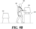
- FIGS. 9A and 9B are views illustrating an operating principle of the wearable suit according to one embodiment of the present disclosure.
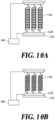
- FIGS. 10A and 10B are views illustrating an operating principle of the muscular strength assistance unit according to one embodiment of the present disclosure.
- the user 200 wearing the wearable suit 100 approaches the weight 910 to move a weight 910 to a work table 920.
- the user 200 may extend the arm or bend the waist to lift the weight 910.
- the muscular strength assistance spring 112a formed of the shape memory alloy material is expanded.
- the user 200 may transmit an operation signal of the wearable suit 100 to the control unit 150 using a switch or the like.
- the control unit 150 controls the power supply unit 160 so that power is supplied from the power supply unit 160 to the muscular strength assistance unit 112. Heat is generated by electric power supplied from the power supply unit 160 and the electrical resistance of the muscular strength assistance spring 112a.
- the temperature of the muscular strength assistance spring 112a increases and the muscular strength assistance spring 112a is contracted.
- the muscular strength assistance spring 112a is contracted, it is possible to assist the muscular strength of the body of the user connected to the muscular strength assistance unit 112. As a result, the user 200 may move the weight 910 to the work table 920 with a small force.
- FIGS. 11A to 11C are views illustrating an operating principle of the sensing unit according to one embodiment of the present disclosure.
- the wearable suit 100 may further include the sensing unit 400.
- the sensing unit 400 senses a load acting on the wearable suit 100.
- the sensing unit 400 may transmit the acquired information to the control unit 150.
- the control unit 150 may control the wearable suit 100 based on the information acquired by the sensing unit.
- the sensing unit 400 may include one or more load sensors.
- the sensing unit 400 may be disposed on the connecting unit 140 to sense a load acting on the connecting unit 140.
- the sensing unit 400 may sense the tension acting on the connecting unit 140.
- the sensing unit 400 may be disposed in the middle of the connecting unit 140.
- the sensing unit 400 may be disposed on the connecting unit 140 to detect loads acting on the connecting units 140 on both sides, respectively.
- the muscular strength assistance spring 112a is expanded, and the connecting units 140 on both sides of the sensing unit 400 maintain a loose state.
- the muscular strength assistance spring 112a is contracted, and both connecting units 140 on both sides of the sensing unit 400 are tense.
- the load acting on the connecting unit 140 between the sensing unit 400 and the coupling unit 130 is reduced.
- the sensing unit 400 transmits information on the load acting on the connecting unit 140 to the control unit 150, and the control unit 150 releases the operation of the wearable suit 100 based on the information.
- the control unit 150 releases the operation of the wearable suit 100 based on the information.
- the wearable suit uses a muscular strength assistance unit formed of the shape memory alloy material to assist muscular strength of the user, thereby simplifying the structure, reducing weight, and removing noise caused by driving of a motor.
- Various implementations of the systems and techniques described herein may be realized by a digital electronic circuit, an integrated circuit, a field programmable gate array (FPGA), an application specific integrated circuit (ASIC), computer hardware, firmware, software, and/or a combination thereof.
- FPGA field programmable gate array
- ASIC application specific integrated circuit
- These various implementations may include being implemented in one or more computer programs executable on a programmable system.
- the programmable system includes at least one programmable processor (which may be a special purpose processor or may be a general-purpose processor) coupled to receive data and instructions from, and transmit data and instructions to, a storage system, at least one input device, and at least one output device.
- Computer programs also known as programs, software, software applications or code
- the computer-readable recording medium includes all types of recording devices in which data readable by a computer system is stored. These computer-readable recording media may be non-volatile or non-transitory medium, such as ROM, CD-ROM, magnetic tape, floppy disk, memory card, hard disk, magneto-optical disk, and storage device, and may further include a transitory medium such as a data transmission medium. In addition, the computer-readable recording medium may be distributed in a network-connected computer system, and the computer-readable code may be stored and executed in a distributed manner.
- a programmable computer includes a programmable processor, a data storage system (including volatile memory, non-volatile memory, or other types of storage systems or combinations thereof) and at least one communication interface.
- a programmable computer may be one of a server, a network appliance, a set-top box, an embedded device, a computer expansion module, a personal computer, a laptop, a Personal Data Assistant (PDA), a cloud computing system, or a mobile device.
- PDA Personal Data Assistant
Landscapes
- Engineering & Computer Science (AREA)
- Robotics (AREA)
- Mechanical Engineering (AREA)
- Health & Medical Sciences (AREA)
- Epidemiology (AREA)
- Pain & Pain Management (AREA)
- Physical Education & Sports Medicine (AREA)
- Rehabilitation Therapy (AREA)
- Life Sciences & Earth Sciences (AREA)
- Animal Behavior & Ethology (AREA)
- General Health & Medical Sciences (AREA)
- Public Health (AREA)
- Veterinary Medicine (AREA)
- Manipulator (AREA)
- Rehabilitation Tools (AREA)
Abstract
Description
- The present disclosure relates to a wearable suit.
- The content described here merely provides background information for the present disclosure and does not constitute the prior art.
- A wearable robot and a wearable suit (hereinafter collectively a "wearable suit") refer to a type of robot that is worn on a human body. A user is directly in charge of posture control, context-awareness, and motion signal generation, which artificial intelligence of the robot is responsible for, and the wearable suit responds to various situations to assist muscular strength and mobility of the user or the like.
- With the development of sensors, control, and software technologies, the wearable suits are being used in various fields such as military use, disaster relief, industrial work, rehabilitation treatment, and daily life assistance. The wearable suit can increase a work performance time and a work range of the user by assisting physical ability of the user in environments such as disaster sites and mountainous terrain. The wearable suit may be used for work and rehabilitation treatment by assisting the muscular strength and physical defects of the user in daily life.
- The wearable suit may be divided into a passive type suit and an active type suit according to a power implementation method. Here, the passive type means a method using a preset force such as a spring and an elastic band, and the active type means a method using a variable force such as a motor and hydraulic pressure.
- This Summary is provided to introduce a selection of concepts in simplified form that are further described below in the Detailed Description. This Summary is not intended to identify key features or essential features of the claimed subject matter, nor is it intended to be used as an aid in determining the scope of the claimed subject matter.
- In one general aspect, a wearable suit configured to assist muscular strength of a user, the wearable suit comprising: a body unit; a fixing unit configured to fix the body unit to an upper body of the user; an arm coupling unit coupled to at least a portion of an arm of the user; and an arm connecting unit configured to connect the body unit and the arm coupling unit to each other, wherein the body unit comprises a housing defining an accommodating space therein; and a muscular strength assistance unit disposed inside the housing and comprising at least a portion comprised of a shape memory alloy material.
- The wearable suit may include a guiding unit configured to guide a position of the arm connecting unit.
- The guiding unit may include at least one guiding member to accommodate at least a portion of the arm connecting unit.
- The at least one guiding member may include a first guiding member including one side connected to the housing and disposed such that at least a portion of the arm connecting unit is inserted.
- In a state in which the user wears the wearable suit, one portion of the first guiding member may extend in a direction toward an upper side of the user from the housing, and a remaining portion of the first guiding member may extend in a direction from the one portion of the first guiding member toward a front of the user.
- The at least one guiding member may include a second guiding member including at least a portion coupled to the fixing unit and disposed such that at least a portion of the arm connecting unit is inserted.
- The second guiding member may be integral with at least a portion of the fixing unit.
- At least a portion of the at least one guiding member may be curved.
- The wearable suit may include: a leg coupling unit coupled to at least a portion of a leg of the user; and a leg connecting unit configured to connect the body unit and the leg coupling unit to each other.
- The fixing unit may include one or more of a shoulder belt, a chest belt, a waist belt, and a leg belt.
- The fixing unit may be vest shaped.
- The muscular strength assistance unit may include at least one muscular strength assistance spring, and the at least one muscular strength assistance spring may be formed of a shape memory alloy material.
- The muscular strength assistance unit may include two or more muscular strength assistance springs and the muscular strength assistant springs may be disposed in at least one form of series and parallel.
- The wearable suit may include a power supply unit configured to supply power to the muscular strength assistance unit, and at least a portion of the muscular strength assistance unit may be expanded and contracted based on the power.
- Other features and aspects will be apparent from the following detailed description, the drawings, and the claims.
-
-
FIG. 1 is a view illustrating a configuration of a wearable suit according to one embodiment of the present disclosure. -
FIG. 2 is a view illustrating a state of a user wearing the wearable suit according to one embodiment of the present disclosure. -
FIG. 3 is a view illustrating a fixing unit according to another embodiment of the present disclosure. -
FIG. 4 is a block diagram of the wearable suit according to one embodiment of the present disclosure. -
FIG. 5 is a view illustrating the wearable suit installed with a first guiding member according to one embodiment of the present disclosure. -
FIG. 6 is a view illustrating the wearable suit installed with a second guiding member according to one embodiment of the present disclosure. -
FIG. 7 is a view illustrating the wearable suit installed with a third guiding member according to one embodiment of the present disclosure. -
FIGS. 8A and8B are views illustrating several embodiments of a leg connecting unit according to the present disclosure. -
FIGS. 9A and9B are views illustrating an operating principle of the wearable suit according to one embodiment of the present disclosure. -
FIGS. 10A and 10B are views illustrating an operating principle of a muscular strength assistance unit according to one embodiment of the present disclosure. -
FIGS. 11A, 11B and11C are views illustrating an operating principle of a sensing unit according to one embodiment of the present disclosure. -
- 100:
- wearable suit
- 110:
- body unit
- 120:
- fixing unit
- 130:
- coupling unit
- 140:
- connecting unit
- A wearable suit according to one embodiment uses a muscular strength assistance unit formed of a shape memory alloy material to assist muscular strength of a user, thereby simplifying a structure, reducing weight, and removing noise caused by driving of a motor.
- The object to be achieved by the present disclosure is not limited to the above-mentioned object, and other objectives not mentioned will be clearly understood by those skilled in the art from the following description.
- Hereinafter, some exemplary embodiments of the present disclosure will be described in detail with reference to the accompanying drawings. In the following description, like reference numerals preferably designate like elements, although the elements are shown in different drawings. Further, in the following description of some embodiments, a detailed description of known functions and configurations incorporated therein will be omitted for the purpose of clarity and for brevity.
- Additionally, various terms such as first, second, A, B, (a), (b), etc., are used solely to differentiate one component from the other but not to imply or suggest the substances, order, or sequence of the components. Throughout this specification, when a part 'includes' or 'comprises' a component, the part is meant to further include other components, not to exclude thereof unless specifically stated to the contrary. The terms such as 'unit', 'module', and the like refer to one or more units for processing at least one function or operation, which may be implemented by hardware, software, or a combination thereof.
-
FIG. 1 is a view illustrating a configuration of a wearable suit according to one embodiment of the present disclosure. -
FIG. 2 is a view illustrating a state of a user wearing the wearable suit according to one embodiment of the present disclosure. -
FIG. 3 is a view illustrating a fixing unit according to another embodiment of the present disclosure. -
FIG. 4 is a block diagram of the wearable suit according to one embodiment of the present disclosure. - Referring to
FIGS. 1 to 4 , awearable suit 100 according to one embodiment of the present disclosure may include abody unit 110, a fixingunit 120, acoupling unit 130, a connectingunit 140, acontrol unit 150, and apower supply unit 160. - The
body unit 110 may include ahousing 111 and a muscularstrength assistance unit 112. - The muscular
strength assistance unit 112 may include a muscularstrength assistance spring 112a, a terminal 112b, and a supportingmember 112c. - The fixing
unit 120 may include ashoulder belt 121, achest belt 122, and awaist belt 123. - The
coupling unit 130 may include anarm coupling unit 131 and aleg coupling unit 132. - The connecting
unit 140 may include anarm connecting unit 141 and aleg connecting unit 142. - The
body unit 110 is disposed in at least a portion of an upper body of auser 200. Thebody unit 110 may be disposed at the rear of the upper body of theuser 200. At least a portion of thebody unit 110 is formed of a shape memory alloy material. Thebody unit 110 may be connected to at least a portion of the fixingunit 120. Thebody unit 110 may be connected to theshoulder belt 121 and thewaist belt 123. Thebody unit 110 is connected to the connectingunit 140. Thebody unit 110 is connected to thecoupling unit 130 using the connectingunit 140. Thecontrol unit 150 may control thebody unit 110 so that thebody unit 110 is activated or deactivated. - The
housing 111 is disposed in at least a portion of the upper body of theuser 200. Thehousing 111 may include an accommodation space therein. In the accommodation space inside thehousing 111, at least a portion of the muscularstrength assistance unit 112, thecontrol unit 150, thepower supply unit 160, a guiding unit (500, 600, 700, refer toFIGS. 5 to 7 ), and the connectingunit 140 may be disposed. Thehousing 111 and theshoulder belt 121 may be formed in a backpack shape. - The muscular
strength assistance unit 112 is configured to assist the muscular strength of theuser 200. The muscularstrength assistance unit 112 may be disposed inside thehousing 111. At least a portion of the muscularstrength assistance unit 112 is formed of a shape memory alloy material. At least a portion of the muscularstrength assistance unit 112 may be contracted and expanded. Power may be applied to the muscularstrength assistance unit 112 by thepower supply unit 160. At least a portion of the muscularstrength assistance unit 112 is connected to the connectingunit 140. The muscularstrength assistance unit 112 may be connected to thecoupling unit 130 using a connectingunit 140. There may be a plurality of muscularstrength assistance units 112. The muscularstrength assistance unit 112 may be controlled by acontrol unit 150. - The muscular
strength assistance spring 112a is formed of a shape memory alloy material. The muscularstrength assistance spring 112a is configured to be contractible and expandable. The muscularstrength assistance spring 112a may be disposed inside thehousing 111. The muscularstrength assistance spring 112a may be electrically connected to the terminal 112b. The muscularstrength assistance spring 112a may be connected to the supportingmember 112c. As the muscularstrength assistance spring 112a is contracted or expanded, the terminal 112b and the supportingmember 112c may move. In this way, compared to a case of driving only the motor, when the muscularstrength assistance spring 112a is used as a driving source of thewearable suit 100, the weight of thewearable suit 100 can be reduced, and noise caused by the driving of the motor can be reduced. - The muscular
strength assistance spring 112a may be contracted and expanded using the power supplied from thepower supply unit 160. Heat is generated by the electric power applied to the muscularstrength assistance spring 112a and electrical resistance of the muscularstrength assistance spring 112a. As the temperature of the muscularstrength assistance spring 112a increases, the muscularstrength assistance spring 112a is contracted. As the electric power supplied to the muscularstrength assistance spring 112a is cut off, the muscularstrength assistance spring 112a may be cooled. - There may be a plurality of muscular
strength assistance springs 112a. The plurality of muscularstrength assistance springs 112a may be disposed in series and/or parallel to each other. In this case, the plurality of muscularstrength assistance springs 112a may be disposed in an appropriate shape in consideration of the resistance of the muscularstrength assistance spring 112a and power supplied from thepower supply unit 160. - The terminal 112b may be formed on the supporting
member 112c. The terminal 112b may be electrically connected to the muscularstrength assistance spring 112a. The terminal 112b may be electrically connected to thepower supply unit 160. The terminal 112b may transmit power supplied from thepower supply unit 160 to the muscularstrength assistance spring 112a. The terminal 112b may be connected to the muscularstrength assistance spring 112a and/or the supportingmember 112c. As the muscularstrength assistance spring 112a is contracted or expanded, the terminal 112b may move together with the supportingmember 112c. The terminal 112b may be disposed inside thehousing 111. - The supporting
member 112c is connected to the muscularstrength assistance spring 112a and/or the terminal 112b to support the muscularstrength assistance spring 112a and/or the terminal 112b. The supportingmember 112c may be disposed on both sides of the muscularstrength assistance spring 112a. The supportingmember 112c may be disposed inside thehousing 111. The terminal 112b may be formed on the supportingmember 112c. There may be a plurality of supportingmembers 112c. Some of the plurality of supportingmembers 112c may be connected to the connectingunit 140. The supportingmember 112c connected to the connectingunit 140 may move as the muscularstrength assistance spring 112a is contracted or expanded to assist the muscular strength of theuser 200. Other supportingmembers 112c of the plurality of supportingmembers 112c may be fixed to the inside of thehousing 111. For example, at least some of the plurality of supportingmembers 112c connected to the connectingunit 140 may be movably installed with respect to thehousing 111, and at least some not connected to the connectingunit 140 may be installed to be fixed to thehousing 111. - The fixing
unit 120 fixes thebody unit 110 to the upper body of theuser 200. At least a portion of the fixingunit 120 may be connected to thehousing 111. The fixingunit 120 may include one or more of theshoulder belt 121, thechest belt 122, thewaist belt 123, and the leg belt. - The
shoulder belt 121 fixes the body unit 1 10 to the upper body of theuser 200. When theuser 200 wears thewearable suit 100, theshoulder belt 121 may be configured to surround the shoulder of theuser 200. Both sides of theshoulder belt 121 may be connected to thehousing 111. At least a portion of thechest belt 122 may be connected to theshoulder belt 121. - The
chest belt 122 fixes thebody unit 110 to the upper body of theuser 200. When theuser 200 wears thewearable suit 100, thechest belt 122 may be configured to surround the chest of theuser 200. At least a portion of thechest belt 122 may be connected to theshoulder belt 121. A middle portion of thechest belt 122 may be formed in a structure capable of being coupled and detached. - The
waist belt 123 fixes thebody unit 110 to the upper body of theuser 200. When theuser 200 wears thewearable suit 100, thewaist belt 123 may be configured to surround the waist of theuser 200. Both sides of thewaist belt 123 may be connected to thehousing 111. A middle portion of thewaist belt 123 may be formed in a structure that is coupled and detachable. According to thewaist belt 123, it is possible to stably maintain a state in which thebody unit 110 is positioned in the upper body of theuser 200. Meanwhile, even when thewaist belt 123 is not provided, thebody unit 110 can be positioned at the upper body of theuser 200 by a fixing force of the leg belt, which will be described later, or by the own weight and theshoulder belt 121 of thebody unit 110. - The leg belt may fix the
body unit 110 to the upper body of theuser 200. When thewearable suit 100 assists the muscular strength of the arm of theuser 200, the leg belt fixes thebody unit 110 to the upper body of theuser 200. In this case, theleg coupling unit 132 and theleg connecting unit 142 may serve as the leg belt. Meanwhile, when thewearable suit 100 assists only the arm of theuser 200, the leg belt may be omitted. - For example, the fixing
unit 120 may be provided in the form of a vest. In the fixingunit 120 in the form of a vest, it may be understood that two or more of theshoulder belt 121, thechest belt 122, and thewaist belt 123 are integrally formed. For example, the fixingunit 120 may be formed in a shape in which the left andright shoulder belts 121 are interconnected by a fastening means, for example, a zipper or a button. - The
coupling unit 130 is coupled to at least a portion of the body of theuser 200. Thecoupling unit 130 may be coupled to at least a portion of the arm and/or leg of theuser 200. Thecoupling unit 130 may be connected to thebody unit 110 by the connectingunit 140. Thecoupling unit 130 may be connected to the muscularstrength assistance unit 112 to assist the muscular strength of theuser 200. There may be a plurality ofcoupling units 130. Thecoupling unit 130 may be formed in a band shape. - The
arm coupling unit 131 is coupled to at least a portion of the arm of theuser 200. Thearm coupling unit 131 may be connected to the muscularstrength assistance unit 112 by thearm connecting unit 141 and assist the muscular strength of the arm of theuser 200. - The
leg coupling unit 132 is coupled to at least a portion of the leg of theuser 200. Theleg coupling unit 132 may be connected to the muscularstrength assistance unit 112 by theleg connecting unit 142, and may assist the muscular strength of the leg and/or the waist of theuser 200. When thewearable suit 100 assists the muscular strength of the arm of theuser 200, theleg coupling unit 132 may constitute a portion of the leg belt. - The connecting
unit 140 connects thebody unit 110 and thecoupling unit 130 to each other. The connectingunit 140 connects the muscularstrength assistance unit 112 and thecoupling unit 130 to each other. At least a portion of the connectingunit 140 may move as the muscularstrength assistance spring 112a is contracted or expanded. For example, the connectingunit 140 may be formed of a non-stretchable material. For example, at least a portion of the connectingunit 140 may be formed of a polyester material. A thickness of the connectingunit 140 may be 8 mm to 10 mm. At least a portion of the connectingunit 140 is inserted into the inside of the guiding member (500, 600, 700, refer toFIGS. 5 to 7 ), and thus, the position of the connectingunit 140 may be guided and/or fixed. - The
arm connecting unit 141 connects thebody unit 110 and thearm coupling unit 131 to each other. Thearm connecting unit 141 connects the muscularstrength assistance unit 112 and thearm coupling unit 131 to each other. As the muscularstrength assistance spring 112a is contracted or expanded, at least a portion of thearm connecting unit 141 may move to assist the muscular strength of the arm of theuser 200. - Meanwhile, when the
wearable suit 100 is provided to assist the muscular strength of the leg and/or the waist of theuser 200, thearm coupling unit 131 and thearm connecting unit 141 may be omitted. - The
leg connecting unit 142 connects thebody unit 110 and theleg coupling unit 132 to each other. Theleg connecting unit 142 connects the muscularstrength assistance unit 112 and theleg coupling unit 132 to each other. As the muscularstrength assistance spring 112a is contracted or expanded, at least a portion of theleg connecting unit 142 may move to assist the muscular strength of the leg and/or the waist of theuser 200. When thewearable suit 100 assists the muscular strength of the arm of theuser 200, theleg connecting unit 142 may constitute a portion of the leg belt. Theleg connecting unit 142 may be formed in a "Y" shape or an "H" shape. Theleg connecting unit 142 may be formed integrally, but is not necessarily limited thereto, and may be formed in a shape in which a plurality of components are combined according to the purpose and use. - Meanwhile, when the
wearable suit 100 is provided to assist the muscular strength of the arm of theuser 200, theleg coupling unit 132 and theleg connecting unit 142 may be omitted. - The
control unit 150 may control each configuration of thewearable suit 100. Thecontrol unit 150 may be disposed inside thehousing 111. Thecontrol unit 150 may receive information acquired by asensing unit 400. Thecontrol unit 150 may receive a signal related to operation or deactivation from a timer and/or a switch. Thecontrol unit 150 may control thepower supply unit 160 based on information obtained by thesensing unit 400. Thecontrol unit 150 may control thebody unit 110 using thepower supply unit 160. - The
control unit 150 may operate thewearable suit 100 based on an operation signal transmitted from a switch or the like. In this case, thecontrol unit 150 may operate thewearable suit 100 by controlling thepower supply unit 160 to supply power from thepower supply unit 160 to the muscularstrength assistance unit 112. - The
control unit 150 may cancel the operation of thewearable suit 100 based on the information transmitted from a timer and/or thesensing unit 400. In this case, thecontrol unit 150 controls thepower supply unit 160 so that the power supplied from thepower supply unit 160 to the muscularstrength assistance unit 112 is cut off, thereby canceling the operation of thewearable suit 100. Thecontrol unit 150 may release the operation of thewearable suit 100 based on information transmitted from the timer. Thecontrol unit 150 may release the operation of thewearable suit 100 based on information on a load acting on thewearable suit 100. Thecontrol unit 150 may release the operation of thewearable suit 100 based on whether the load acting on the connectingunit 140 decreases and/or whether a load reduction time is equal to or longer than a preset time. - The
power supply unit 160 may be electrically connected to at least a portion of the muscularstrength assistance unit 112 to supply power to the muscularstrength assistance unit 112. Thepower supply unit 160 may be electrically connected to the terminal 112b. Thepower supply unit 160 may be disposed inside thehousing 111. Heat is generated by the electric power supplied from thepower supply unit 160 and the electrical resistance of the muscularstrength assistance spring 112a, and the temperature of the muscularstrength assistance spring 112a increases. Accordingly, the muscularstrength assistance spring 112a is contracted and provides tension to the connectingunit 140 to assist the muscular strength of the body part of the user equipped with thecoupling unit 130, that is, the arm, waist and/or leg. Thepower supply unit 160 may be controlled by thecontrol unit 150 to supply or cut power to the muscularstrength assistance unit 112. -
FIG. 5 is a view illustrating the wearable suit installed with a first guiding member according to one embodiment of the present disclosure. -
FIG. 6 is a view illustrating the wearable suit installed with a second guiding member according to one embodiment of the present disclosure. -
FIG. 7 is a view illustrating the wearable suit installed with a third guiding member according to one embodiment of the present disclosure. - The guiding unit according to one embodiment of the present disclosure will be described in detail with reference to
FIGS. 5 to 7 . - The
wearable suit 100 according to the present disclosure may further include the guiding unit configured to guide the position of the connectingunit 140. The guiding unit allows the connectingunit 140 to move along a set path, and thus, it is possible to further improve control accuracy. - The guiding unit may include one or
more guiding members unit 140. - The guiding
members member 500, asecond guiding member 600, and athird guiding member 700.FIG. 5 to 7 illustrate each of the guidingmembers wearable suit 100 may include two ormore guiding members - The
first guiding member 500 may guide and/or fix the position of thearm connecting unit 141. Thefirst guiding member 500 is configured to accommodate at least a portion of thearm connecting unit 141. Thefirst guiding member 500 prevents thearm connecting unit 141 from coming into direct contact with the body of the user, and thus, it is possible to reduce the problem that the user is injured in the process of thearm connecting unit 141 moving. One side of the first guidingmember 500 toward the upper side and/or the front of the user from thehousing 111 may be connected to thehousing 111. For example, as illustrated inFIG. 5 , based on the state in which the user wears thewearable suit 100, the first guidingmember 500 may have a shape extending from thehousing 111 toward the upper side and/or the front of the user. Based on the state in which theuser 200 wears thewearable suit 100, one portion of the first guidingmember 500 may extend from thehousing 111 toward the upper side of theuser 200, and the remaining portion of the first guidingmember 500 may extend in a direction toward the front of theuser 200 from the one portion. According to the first guidingmember 500, it is possible to prevent a load due to the tension applied to thearm connecting unit 141 from concentrating on the shoulder of the user. Thefirst guiding member 500 may be formed in a pipe shape having a hollow into which at least a portion of thearm connecting unit 141 is inserted. According to such a shape, it is possible to guide the position of thearm connecting unit 141 more stably. Meanwhile, unlike this, the first guidingmember 500 may have a groove shape with an open upper side. At least a portion of the first guidingmember 500 may be bent so that the load acting on the first guidingmember 500 and thearm connecting unit 141 is distributed. There may be a plurality of first guidingmembers 500. - For example, an end of the first guiding
member 500 may have a downwardly curved shape. According to such a shape, it is possible to prevent thearm connecting unit 141 from being damaged by friction with the end portion of the first guidingmember 500. - The
second guiding member 600 may guide and/or fix the position of thearm connecting unit 141. Thesecond guiding member 600 is configured to accommodate at least a portion of thearm connecting unit 141. Thesecond guiding member 600 may be coupled to at least a portion of the fixingunit 120. Thesecond guiding member 600 may be coupled to at least a portion of theshoulder belt 121. For example, the second guidingmember 600 may be formed integrally with the fixing unit 120 (for example, shoulder belt 121) in the form of a passage formed to pass through the fixing unit 120 (for example, shoulder belt 121). Thesecond guiding member 600 may be formed in a pipe or ring shape. Meanwhile, unlike this, the second guidingmember 600 may have a groove shape with an open upper side. At least a portion of the second guidingmember 600 may be bent so that the load acting on the second guidingmember 600 is distributed. There may be a plurality of second guidingmembers 600. - The
third guiding member 700 may guide and/or fix the position of theleg connecting unit 142. Thethird guiding member 700 is configured such that at least a portion of theleg connecting unit 142 is inserted. Thethird guiding member 700 may be disposed inside thehousing 111. Thethird guiding member 700 may be fixed to the inside of thehousing 111. Thethird guiding member 700 may be formed in a pipe or ring shape. There may be a plurality of third guidingmembers 700. -
FIGS. 8A and8B are views illustrating several embodiments of the leg connecting unit according to the present disclosure. - Referring to
FIGS. 8A and8B , theleg connecting unit 142 according to one embodiment of the present disclosure may include a firstleg connecting unit 810, a secondleg connecting unit 820 and a thirdleg connecting unit 830. - One side of the first
leg connecting unit 810 is connected to thebody unit 110. One side of the firstleg connecting unit 810 may be connected to the supportingmember 112c of the muscularstrength assistance unit 112. As the muscularstrength assistance spring 112a is contracted or expanded, at least a portion of the firstleg connecting unit 810 may move together with the supportingmember 112c. The other side of the firstleg connecting unit 810 may be connected to the thirdleg connecting unit 830. The firstleg connecting unit 810 may be connected to the secondleg connecting unit 820 by the thirdleg connecting unit 830. A crosssection of the firstleg connecting unit 810 may have a circular shape. The firstleg connecting unit 810 may be formed of a polyester material. There may be a plurality of firstleg connecting unit 810. According to the purpose and use, the firstleg connecting unit 810 may be formed in various lengths. - One side of the second
leg connecting unit 820 is connected to theleg coupling unit 132. The other side of the secondleg connecting unit 820 may be connected to the thirdleg connecting unit 830. The secondleg connecting unit 820 may be connected to the firstleg connecting unit 810 by the thirdleg connecting unit 830. The secondleg connecting unit 820 may be formed of a polyester material. The secondleg connecting unit 820 may have a shape having a width larger than a thickness. According to such a shape, based on the state in which the user is seated in a chair for rest, by thinning a thickness of a portion of theleg connecting unit 142 in contact with the body (for example, waist, buttocks, and/or thigh) of the user, it is possible to sufficiently secure the rigidity of the secondleg connecting unit 820 while relieving the discomfort during seating. For example, the secondleg connecting unit 820 may be formed in a thin and flat shape (for example, a webbing belt shape) similar to a seat belt of a vehicle. There may be a plurality of secondleg connecting unit 820. According to the purpose and use, the secondleg connecting unit 820 may be formed in various lengths. - The third
leg connecting unit 830 is disposed between the firstleg connecting unit 810 and the secondleg connecting unit 820. The thirdleg connecting unit 830 connects the other side of the firstleg connecting unit 810 and the other side of the secondleg connecting unit 820 to each other. The thirdleg connecting unit 830 may support and/or fix the firstleg connecting unit 810 and the secondleg connecting unit 820. The thirdleg connecting unit 830 may be formed in a ring or bar shape. - For example, as illustrated in
FIG. 8A , when the thirdleg connecting unit 830 is formed in a ring shape, according to such a structure, the structure is simple, and it is possible to improve a right-left balance of the secondleg connecting unit 820. For example, the secondleg connecting unit 820 may be installed in the thirdleg connecting unit 830 to be movable along a periphery of the thirdleg connecting unit 830. - For example, as illustrated in
FIG. 8B , when the thirdleg connecting unit 830 is formed in a bar shape, by sufficiently separating a distance between the pair of secondleg connecting unit 820, it is possible to reduce a portion of the secondleg connecting unit 820 in contact with the buttocks of the user. In addition, by reducing an angle formed by the secondleg connecting unit 820 in a transmission direction of the force from the muscularstrength assistance unit 112 to theleg coupling unit 132, it is possible to improve efficiency of force transmission. -
FIGS. 9A and9B are views illustrating an operating principle of the wearable suit according to one embodiment of the present disclosure. -
FIGS. 10A and 10B are views illustrating an operating principle of the muscular strength assistance unit according to one embodiment of the present disclosure. - The operating principle of the
wearable suit 100 according to one embodiment of the present disclosure will be described with reference toFIGS. 9A to 10B . - The
user 200 wearing thewearable suit 100 approaches theweight 910 to move aweight 910 to a work table 920. Theuser 200 may extend the arm or bend the waist to lift theweight 910. Accordingly, the muscularstrength assistance spring 112a formed of the shape memory alloy material is expanded. Theuser 200 may transmit an operation signal of thewearable suit 100 to thecontrol unit 150 using a switch or the like. Thecontrol unit 150 controls thepower supply unit 160 so that power is supplied from thepower supply unit 160 to the muscularstrength assistance unit 112. Heat is generated by electric power supplied from thepower supply unit 160 and the electrical resistance of the muscularstrength assistance spring 112a. The temperature of the muscularstrength assistance spring 112a increases and the muscularstrength assistance spring 112a is contracted. As the muscularstrength assistance spring 112a is contracted, it is possible to assist the muscular strength of the body of the user connected to the muscularstrength assistance unit 112. As a result, theuser 200 may move theweight 910 to the work table 920 with a small force. -
FIGS. 11A to 11C are views illustrating an operating principle of the sensing unit according to one embodiment of the present disclosure. - Referring to
FIG. 11 , thewearable suit 100 according to one embodiment of the present disclosure may further include thesensing unit 400. - The
sensing unit 400 senses a load acting on thewearable suit 100. Thesensing unit 400 may transmit the acquired information to thecontrol unit 150. Thecontrol unit 150 may control thewearable suit 100 based on the information acquired by the sensing unit. Thesensing unit 400 may include one or more load sensors. Thesensing unit 400 may be disposed on the connectingunit 140 to sense a load acting on the connectingunit 140. Thesensing unit 400 may sense the tension acting on the connectingunit 140. Thesensing unit 400 may be disposed in the middle of the connectingunit 140. - The
sensing unit 400 may be disposed on the connectingunit 140 to detect loads acting on the connectingunits 140 on both sides, respectively. As theuser 200 extends the arm or bends the waist to move theweight 910, the muscularstrength assistance spring 112a is expanded, and the connectingunits 140 on both sides of thesensing unit 400 maintain a loose state. As theuser 200 operates thewearable suit 100 to lift theweight 910, the muscularstrength assistance spring 112a is contracted, and both connectingunits 140 on both sides of thesensing unit 400 are tense. When theuser 200 puts down theweight 910 from his/her hand, the load acting on the connectingunit 140 between thesensing unit 400 and thecoupling unit 130 is reduced. Thesensing unit 400 transmits information on the load acting on the connectingunit 140 to thecontrol unit 150, and thecontrol unit 150 releases the operation of thewearable suit 100 based on the information. When theuser 200 is holding an object in both hands, there is a problem in that it is difficult to use the switch. However, according to the above-described structure, it is possible to release the operation of thewearable suit 100 according to the intention of theuser 200 without a separately installed switch or the like. - According to one embodiment, the wearable suit uses a muscular strength assistance unit formed of the shape memory alloy material to assist muscular strength of the user, thereby simplifying the structure, reducing weight, and removing noise caused by driving of a motor.
- Various implementations of the systems and techniques described herein may be realized by a digital electronic circuit, an integrated circuit, a field programmable gate array (FPGA), an application specific integrated circuit (ASIC), computer hardware, firmware, software, and/or a combination thereof. These various implementations may include being implemented in one or more computer programs executable on a programmable system. The programmable system includes at least one programmable processor (which may be a special purpose processor or may be a general-purpose processor) coupled to receive data and instructions from, and transmit data and instructions to, a storage system, at least one input device, and at least one output device. Computer programs (also known as programs, software, software applications or code) include instructions for a programmable processor and are stored on a "computer-readable medium".
- The computer-readable recording medium includes all types of recording devices in which data readable by a computer system is stored. These computer-readable recording media may be non-volatile or non-transitory medium, such as ROM, CD-ROM, magnetic tape, floppy disk, memory card, hard disk, magneto-optical disk, and storage device, and may further include a transitory medium such as a data transmission medium. In addition, the computer-readable recording medium may be distributed in a network-connected computer system, and the computer-readable code may be stored and executed in a distributed manner.
- Various implementations of the systems and techniques described herein may be implemented by a programmable computer. Here, the computer includes a programmable processor, a data storage system (including volatile memory, non-volatile memory, or other types of storage systems or combinations thereof) and at least one communication interface. For example, a programmable computer may be one of a server, a network appliance, a set-top box, an embedded device, a computer expansion module, a personal computer, a laptop, a Personal Data Assistant (PDA), a cloud computing system, or a mobile device.
- Although exemplary embodiments of the present disclosure have been described for illustrative purposes, those skilled in the art will appreciate that various modifications, additions, and substitutions are possible, without departing from the idea and scope of the claimed invention. Therefore, exemplary embodiments of the present disclosure have been described for the sake of brevity and clarity. The scope of the technical idea of the present embodiments is not limited by the illustrations. Accordingly, one of ordinary skill would understand the scope of the claimed invention is not to be limited by the above explicitly described embodiments but by the claims and equivalents thereof.
Claims (14)
- A wearable suit configured to assist muscular strength of a user, the wearable suit comprising:a body unit;a fixing unit configured to fix the body unit to an upper body of the user;an arm coupling unit coupled to at least a portion of an arm of the user; andan arm connecting unit configured to connect the body unit and the arm coupling unit to each other,wherein the body unit comprises:a housing defining an accommodating space therein; anda muscular strength assistance unit disposed inside the housing and comprising at least a portion comprised of a shape memory alloy material.
- The wearable suit of claim 1, further comprising a guiding unit configured to guide a position of the arm connecting unit.
- The wearable suit of claim 2, wherein the guiding unit comprises at least one guiding member to accommodate at least a portion of the arm connecting unit.
- The wearable suit of claim 3, wherein the at least one guiding member comprises a first guiding member including one side connected to the housing and disposed such that at least a portion of the arm connecting unit is inserted.
- The wearable suit of claim 4, wherein in a state in which the user wears the wearable suit, one portion of the first guiding member extends in a direction toward an upper side of the user from the housing, and a remaining portion of the first guiding member extends in a direction from the one portion of the first guiding member toward a front of the user.
- The wearable suit of any one of claims 3 to 5, wherein the at least one guiding member comprises a second guiding member including at least a portion coupled to the fixing unit and disposed such that at least a portion of the arm connecting unit is inserted.
- The wearable suit of claim 6, wherein the second guiding member is integral with at least a portion of the fixing unit.
- The wearable suit of any one of claims 3 to 7, wherein at least a portion of the at least one guiding member is curved.
- The wearable suit of any one of claims 1 to 8, further comprising:a leg coupling unit coupled to at least a portion of a leg of the user; anda leg connecting unit configured to connect the body unit and the leg coupling unit to each other.
- The wearable suit of any one of claims 1 to 9, wherein the fixing unit comprises one or more of a shoulder belt, a chest belt, a waist belt, and a leg belt.
- The wearable suit of any one of claims 1 to 10, wherein the fixing unit is vest shaped.
- The wearable suit of any one of claims 1 to 11, wherein the muscular strength assistance unit comprises at least one muscular strength assistance spring, and
the at least one muscular strength assistance spring is comprised of a shape memory alloy material. - The wearable suit of claim 12, wherein the muscular strength assistance unit comprises two or more muscular strength assistance springs and the muscular strength assistant springs are disposed in at least one form of series and parallel.
- The wearable suit of any one of claims 1 to 13, further comprising a power supply unit configured to supply power to the muscular strength assistance unit,
wherein at least a portion of the muscular strength assistance unit is expanded and contracted based on the power.
Applications Claiming Priority (1)
| Application Number | Priority Date | Filing Date | Title |
|---|---|---|---|
| KR1020220032369A KR20230135229A (en) | 2022-03-15 | 2022-03-15 | Wearable Suit |
Publications (2)
| Publication Number | Publication Date |
|---|---|
| EP4245470A1 true EP4245470A1 (en) | 2023-09-20 |
| EP4245470B1 EP4245470B1 (en) | 2024-12-04 |
Family
ID=81877963
Family Applications (1)
| Application Number | Title | Priority Date | Filing Date |
|---|---|---|---|
| EP22176270.1A Active EP4245470B1 (en) | 2022-03-15 | 2022-05-31 | Wearable suit |
Country Status (5)
| Country | Link |
|---|---|
| US (1) | US12636215B2 (en) |
| EP (1) | EP4245470B1 (en) |
| KR (3) | KR20230135229A (en) |
| CN (1) | CN116787401A (en) |
| ES (1) | ES3007294T3 (en) |
Families Citing this family (4)
| Publication number | Priority date | Publication date | Assignee | Title |
|---|---|---|---|---|
| KR102852921B1 (en) | 2023-10-11 | 2025-09-02 | 씨제이제일제당 (주) | Automatic metering conveying system and control method of automatic metering conveying system |
| KR102887890B1 (en) * | 2023-10-31 | 2025-11-18 | 위드포스(주) | The connection structure of the SMA spring used in the driver |
| KR20250179477A (en) | 2024-06-21 | 2025-12-30 | 큐렉소 주식회사 | Strength Assistive Device and method for the Device |
| KR102997546B1 (en) | 2024-11-21 | 2026-07-30 | 서울과학기술대학교 산학협력단 | SMA-Walking aid with fan-spray hybrid cooling |
Citations (3)
| Publication number | Priority date | Publication date | Assignee | Title |
|---|---|---|---|---|
| CN107648017A (en) * | 2017-11-09 | 2018-02-02 | 上海司羿智能科技有限公司 | Exoskeleton driving device, power-assisted exoskeleton system, and driving and power-assisted methods thereof |
| EP3378606A1 (en) * | 2015-11-20 | 2018-09-26 | Kubota Corporation | Assistance suit |
| WO2021118185A2 (en) * | 2019-12-13 | 2021-06-17 | 한국기계연구원 | Soft actuator, soft actuator assembly comprising soft actuator, and wearable robot comprising soft actuator or soft actuator assembly |
Family Cites Families (10)
| Publication number | Priority date | Publication date | Assignee | Title |
|---|---|---|---|---|
| KR101677920B1 (en) | 2015-02-27 | 2016-11-21 | 한국기술교육대학교기술지주 주식회사 | Wearable Type Exercise Equipment for Upper Limb |
| US10888728B2 (en) * | 2015-04-08 | 2021-01-12 | Aorte Fitness Inc. | Kinetic resistance apparatus |
| DE102016122282A1 (en) * | 2016-11-18 | 2018-05-24 | Helmut-Schmidt-Universität Universität der Bundeswehr Hamburg | SYSTEM AND METHOD FOR REDUCING FORCES AFFORDING ON A SPINE |
| DE102016123153A1 (en) * | 2016-11-30 | 2018-05-30 | Helmut-Schmidt-Universität Universität der Bundeswehr Hamburg | DEVICE AND METHOD FOR MUSCLE POWER SUPPORT |
| JP7182418B2 (en) | 2018-10-04 | 2022-12-02 | 株式会社アドバンス | motion support device |
| US12491626B2 (en) * | 2019-06-24 | 2025-12-09 | Korea Institute Of Machinery & Materials | Soft actuator having cooler, wearable robot having the same, massage device having the same, and method for controlling the same |
| KR102774691B1 (en) * | 2019-08-16 | 2025-03-04 | 엘지전자 주식회사 | Artificial Muscle Module and Wearable Robot having the same |
| US20210077839A1 (en) * | 2019-09-12 | 2021-03-18 | Jtekt Corporation | Assist device |
| KR102388069B1 (en) | 2020-06-11 | 2022-04-20 | 한국기계연구원 | Wearable robot module using a cloth-type flexible actuator, and wearable robot having the same |
| CN112276905A (en) * | 2020-09-15 | 2021-01-29 | 中国科学院深圳先进技术研究院 | Upper limb power assisting device |
-
2022
- 2022-03-15 KR KR1020220032369A patent/KR20230135229A/en not_active Ceased
- 2022-04-29 US US17/732,921 patent/US12636215B2/en active Active
- 2022-05-31 EP EP22176270.1A patent/EP4245470B1/en active Active
- 2022-05-31 ES ES22176270T patent/ES3007294T3/en active Active
- 2022-06-17 CN CN202210690973.7A patent/CN116787401A/en active Pending
-
2024
- 2024-10-08 KR KR1020240136289A patent/KR102742461B1/en active Active
- 2024-12-06 KR KR1020240180178A patent/KR20250003400A/en active Pending
Patent Citations (3)
| Publication number | Priority date | Publication date | Assignee | Title |
|---|---|---|---|---|
| EP3378606A1 (en) * | 2015-11-20 | 2018-09-26 | Kubota Corporation | Assistance suit |
| CN107648017A (en) * | 2017-11-09 | 2018-02-02 | 上海司羿智能科技有限公司 | Exoskeleton driving device, power-assisted exoskeleton system, and driving and power-assisted methods thereof |
| WO2021118185A2 (en) * | 2019-12-13 | 2021-06-17 | 한국기계연구원 | Soft actuator, soft actuator assembly comprising soft actuator, and wearable robot comprising soft actuator or soft actuator assembly |
Also Published As
| Publication number | Publication date |
|---|---|
| US12636215B2 (en) | 2026-05-26 |
| EP4245470B1 (en) | 2024-12-04 |
| ES3007294T3 (en) | 2025-03-19 |
| US20230293378A1 (en) | 2023-09-21 |
| KR20240149870A (en) | 2024-10-15 |
| KR20230135229A (en) | 2023-09-25 |
| KR102742461B1 (en) | 2024-12-12 |
| KR20250003400A (en) | 2025-01-07 |
| CN116787401A (en) | 2023-09-22 |
Similar Documents
| Publication | Publication Date | Title |
|---|---|---|
| EP4245470B1 (en) | Wearable suit | |
| JP7554289B2 (en) | Mobile robot battery system and method | |
| CN109803730B (en) | Exercise assisting device | |
| KR102734351B1 (en) | Wearable robot, motion assistance method and system using state trajectory memory buffer | |
| CN112839779A (en) | Tension generating device and flexion and extension assisting device with tension generating device | |
| JP2016067899A (en) | Brake device for wearable electromechanical device | |
| JP2006320351A (en) | Lumbar orthosis | |
| KR20150134888A (en) | A driving module and a motion assist apparatus | |
| KR20150134889A (en) | A supporting module and a motion assist apparatus | |
| WO2021116721A1 (en) | Motion assistance device | |
| CN112809658B (en) | A passive knee exoskeleton | |
| EP3512484B1 (en) | Legged mobility exoskeleton device with enhanced actuator mechanism employing magnetic/electrical coupling | |
| US20150358450A1 (en) | Accessory for mobile electronic device | |
| KR20230135230A (en) | Wearable Suit | |
| KR20230135228A (en) | Wearable Suit And Control Method Therefor | |
| KR20240092814A (en) | Wearable Suit | |
| US20230293379A1 (en) | Wearable suit and control method thereof | |
| JP2012189067A (en) | Variable sheet and body mounting device using the same | |
| ES3035515T3 (en) | Wearable suit | |
| CN115843237B (en) | Support member with bistable spring and exercise assisting device including the support member | |
| CN218280052U (en) | Exoskeleton belt device and exercise assisting equipment | |
| CN116774814A (en) | Wearable suit and control method thereof | |
| KR20230148436A (en) | Wearable Suit And Control Method Therefor | |
| EP3512482A1 (en) | Legged mobility exoskeleton device with enhanced actuator mechanism employing magnetic coupling | |
| CN216875196U (en) | Intelligent waistband |
Legal Events
| Date | Code | Title | Description |
|---|---|---|---|
| PUAI | Public reference made under article 153(3) epc to a published international application that has entered the european phase |
Free format text: ORIGINAL CODE: 0009012 |
|
| STAA | Information on the status of an ep patent application or granted ep patent |
Free format text: STATUS: REQUEST FOR EXAMINATION WAS MADE |
|
| 17P | Request for examination filed |
Effective date: 20220531 |
|
| AK | Designated contracting states |
Kind code of ref document: A1 Designated state(s): AL AT BE BG CH CY CZ DE DK EE ES FI FR GB GR HR HU IE IS IT LI LT LU LV MC MK MT NL NO PL PT RO RS SE SI SK SM TR |
|
| GRAP | Despatch of communication of intention to grant a patent |
Free format text: ORIGINAL CODE: EPIDOSNIGR1 |
|
| STAA | Information on the status of an ep patent application or granted ep patent |
Free format text: STATUS: GRANT OF PATENT IS INTENDED |
|
| INTG | Intention to grant announced |
Effective date: 20240726 |
|
| GRAS | Grant fee paid |
Free format text: ORIGINAL CODE: EPIDOSNIGR3 |
|
| GRAA | (expected) grant |
Free format text: ORIGINAL CODE: 0009210 |
|
| STAA | Information on the status of an ep patent application or granted ep patent |
Free format text: STATUS: THE PATENT HAS BEEN GRANTED |
|
| P01 | Opt-out of the competence of the unified patent court (upc) registered |
Free format text: CASE NUMBER: APP_56065/2024 Effective date: 20241014 |
|
| AK | Designated contracting states |
Kind code of ref document: B1 Designated state(s): AL AT BE BG CH CY CZ DE DK EE ES FI FR GB GR HR HU IE IS IT LI LT LU LV MC MK MT NL NO PL PT RO RS SE SI SK SM TR |
|
| REG | Reference to a national code |
Ref country code: CH Ref legal event code: EP |
|
| REG | Reference to a national code |
Ref country code: DE Ref legal event code: R096 Ref document number: 602022008317 Country of ref document: DE |
|
| REG | Reference to a national code |
Ref country code: IE Ref legal event code: FG4D |
|
| REG | Reference to a national code |
Ref country code: ES Ref legal event code: FG2A Ref document number: 3007294 Country of ref document: ES Kind code of ref document: T3 Effective date: 20250319 |
|
| REG | Reference to a national code |
Ref country code: LT Ref legal event code: MG9D |
|
| REG | Reference to a national code |
Ref country code: NL Ref legal event code: MP Effective date: 20241204 |
|
| PG25 | Lapsed in a contracting state [announced via postgrant information from national office to epo] |
Ref country code: HR Free format text: LAPSE BECAUSE OF FAILURE TO SUBMIT A TRANSLATION OF THE DESCRIPTION OR TO PAY THE FEE WITHIN THE PRESCRIBED TIME-LIMIT Effective date: 20241204 |
|
| PG25 | Lapsed in a contracting state [announced via postgrant information from national office to epo] |
Ref country code: FI Free format text: LAPSE BECAUSE OF FAILURE TO SUBMIT A TRANSLATION OF THE DESCRIPTION OR TO PAY THE FEE WITHIN THE PRESCRIBED TIME-LIMIT Effective date: 20241204 |
|
| PG25 | Lapsed in a contracting state [announced via postgrant information from national office to epo] |
Ref country code: BG Free format text: LAPSE BECAUSE OF FAILURE TO SUBMIT A TRANSLATION OF THE DESCRIPTION OR TO PAY THE FEE WITHIN THE PRESCRIBED TIME-LIMIT Effective date: 20241204 |
|
| PG25 | Lapsed in a contracting state [announced via postgrant information from national office to epo] |
Ref country code: NO Free format text: LAPSE BECAUSE OF FAILURE TO SUBMIT A TRANSLATION OF THE DESCRIPTION OR TO PAY THE FEE WITHIN THE PRESCRIBED TIME-LIMIT Effective date: 20250304 |
|
| PG25 | Lapsed in a contracting state [announced via postgrant information from national office to epo] |
Ref country code: LV Free format text: LAPSE BECAUSE OF FAILURE TO SUBMIT A TRANSLATION OF THE DESCRIPTION OR TO PAY THE FEE WITHIN THE PRESCRIBED TIME-LIMIT Effective date: 20241204 Ref country code: GR Free format text: LAPSE BECAUSE OF FAILURE TO SUBMIT A TRANSLATION OF THE DESCRIPTION OR TO PAY THE FEE WITHIN THE PRESCRIBED TIME-LIMIT Effective date: 20250305 |
|
| PG25 | Lapsed in a contracting state [announced via postgrant information from national office to epo] |
Ref country code: RS Free format text: LAPSE BECAUSE OF FAILURE TO SUBMIT A TRANSLATION OF THE DESCRIPTION OR TO PAY THE FEE WITHIN THE PRESCRIBED TIME-LIMIT Effective date: 20250304 |
|
| PG25 | Lapsed in a contracting state [announced via postgrant information from national office to epo] |
Ref country code: NL Free format text: LAPSE BECAUSE OF FAILURE TO SUBMIT A TRANSLATION OF THE DESCRIPTION OR TO PAY THE FEE WITHIN THE PRESCRIBED TIME-LIMIT Effective date: 20241204 |
|
| REG | Reference to a national code |
Ref country code: AT Ref legal event code: MK05 Ref document number: 1747667 Country of ref document: AT Kind code of ref document: T Effective date: 20241204 |
|
| PG25 | Lapsed in a contracting state [announced via postgrant information from national office to epo] |
Ref country code: SM Free format text: LAPSE BECAUSE OF FAILURE TO SUBMIT A TRANSLATION OF THE DESCRIPTION OR TO PAY THE FEE WITHIN THE PRESCRIBED TIME-LIMIT Effective date: 20241204 |
|
| PG25 | Lapsed in a contracting state [announced via postgrant information from national office to epo] |
Ref country code: PL Free format text: LAPSE BECAUSE OF FAILURE TO SUBMIT A TRANSLATION OF THE DESCRIPTION OR TO PAY THE FEE WITHIN THE PRESCRIBED TIME-LIMIT Effective date: 20241204 |
|
| PG25 | Lapsed in a contracting state [announced via postgrant information from national office to epo] |
Ref country code: IS Free format text: LAPSE BECAUSE OF FAILURE TO SUBMIT A TRANSLATION OF THE DESCRIPTION OR TO PAY THE FEE WITHIN THE PRESCRIBED TIME-LIMIT Effective date: 20250404 |
|
| PG25 | Lapsed in a contracting state [announced via postgrant information from national office to epo] |
Ref country code: PT Free format text: LAPSE BECAUSE OF FAILURE TO SUBMIT A TRANSLATION OF THE DESCRIPTION OR TO PAY THE FEE WITHIN THE PRESCRIBED TIME-LIMIT Effective date: 20250404 |
|
| PG25 | Lapsed in a contracting state [announced via postgrant information from national office to epo] |
Ref country code: EE Free format text: LAPSE BECAUSE OF FAILURE TO SUBMIT A TRANSLATION OF THE DESCRIPTION OR TO PAY THE FEE WITHIN THE PRESCRIBED TIME-LIMIT Effective date: 20241204 |
|
| PG25 | Lapsed in a contracting state [announced via postgrant information from national office to epo] |
Ref country code: AT Free format text: LAPSE BECAUSE OF FAILURE TO SUBMIT A TRANSLATION OF THE DESCRIPTION OR TO PAY THE FEE WITHIN THE PRESCRIBED TIME-LIMIT Effective date: 20241204 Ref country code: RO Free format text: LAPSE BECAUSE OF FAILURE TO SUBMIT A TRANSLATION OF THE DESCRIPTION OR TO PAY THE FEE WITHIN THE PRESCRIBED TIME-LIMIT Effective date: 20241204 |
|
| PG25 | Lapsed in a contracting state [announced via postgrant information from national office to epo] |
Ref country code: SK Free format text: LAPSE BECAUSE OF FAILURE TO SUBMIT A TRANSLATION OF THE DESCRIPTION OR TO PAY THE FEE WITHIN THE PRESCRIBED TIME-LIMIT Effective date: 20241204 |
|
| PG25 | Lapsed in a contracting state [announced via postgrant information from national office to epo] |
Ref country code: CZ Free format text: LAPSE BECAUSE OF FAILURE TO SUBMIT A TRANSLATION OF THE DESCRIPTION OR TO PAY THE FEE WITHIN THE PRESCRIBED TIME-LIMIT Effective date: 20241204 |
|
| REG | Reference to a national code |
Ref country code: DE Ref legal event code: R097 Ref document number: 602022008317 Country of ref document: DE |
|
| PG25 | Lapsed in a contracting state [announced via postgrant information from national office to epo] |
Ref country code: SE Free format text: LAPSE BECAUSE OF FAILURE TO SUBMIT A TRANSLATION OF THE DESCRIPTION OR TO PAY THE FEE WITHIN THE PRESCRIBED TIME-LIMIT Effective date: 20241204 |
|
| PG25 | Lapsed in a contracting state [announced via postgrant information from national office to epo] |
Ref country code: DK Free format text: LAPSE BECAUSE OF FAILURE TO SUBMIT A TRANSLATION OF THE DESCRIPTION OR TO PAY THE FEE WITHIN THE PRESCRIBED TIME-LIMIT Effective date: 20241204 |
|
| PLBE | No opposition filed within time limit |
Free format text: ORIGINAL CODE: 0009261 |
|
| STAA | Information on the status of an ep patent application or granted ep patent |
Free format text: STATUS: NO OPPOSITION FILED WITHIN TIME LIMIT |
|
| REG | Reference to a national code |
Ref country code: CH Ref legal event code: L10 Free format text: ST27 STATUS EVENT CODE: U-0-0-L10-L00 (AS PROVIDED BY THE NATIONAL OFFICE) Effective date: 20251015 |
|
| 26N | No opposition filed |
Effective date: 20250905 |
|
| REG | Reference to a national code |
Ref country code: CH Ref legal event code: H13 Free format text: ST27 STATUS EVENT CODE: U-0-0-H10-H13 (AS PROVIDED BY THE NATIONAL OFFICE) Effective date: 20251223 |
|
| PG25 | Lapsed in a contracting state [announced via postgrant information from national office to epo] |
Ref country code: LU Free format text: LAPSE BECAUSE OF NON-PAYMENT OF DUE FEES Effective date: 20250531 |
|
| PG25 | Lapsed in a contracting state [announced via postgrant information from national office to epo] |
Ref country code: CH Free format text: LAPSE BECAUSE OF NON-PAYMENT OF DUE FEES Effective date: 20250531 |
|
| REG | Reference to a national code |
Ref country code: BE Ref legal event code: MM Effective date: 20250531 |
|
| PG25 | Lapsed in a contracting state [announced via postgrant information from national office to epo] |
Ref country code: MC Free format text: LAPSE BECAUSE OF FAILURE TO SUBMIT A TRANSLATION OF THE DESCRIPTION OR TO PAY THE FEE WITHIN THE PRESCRIBED TIME-LIMIT Effective date: 20241204 |
|
| PGFP | Annual fee paid to national office [announced via postgrant information from national office to epo] |
Ref country code: GB Payment date: 20260324 Year of fee payment: 5 |
|
| PG25 | Lapsed in a contracting state [announced via postgrant information from national office to epo] |
Ref country code: IE Free format text: LAPSE BECAUSE OF NON-PAYMENT OF DUE FEES Effective date: 20250531 |
|
| PG25 | Lapsed in a contracting state [announced via postgrant information from national office to epo] |
Ref country code: BE Free format text: LAPSE BECAUSE OF NON-PAYMENT OF DUE FEES Effective date: 20250531 |
|
| PGFP | Annual fee paid to national office [announced via postgrant information from national office to epo] |
Ref country code: FR Payment date: 20260323 Year of fee payment: 5 |
|
| PG25 | Lapsed in a contracting state [announced via postgrant information from national office to epo] |
Ref country code: LT Free format text: LAPSE BECAUSE OF FAILURE TO SUBMIT A TRANSLATION OF THE DESCRIPTION OR TO PAY THE FEE WITHIN THE PRESCRIBED TIME-LIMIT Effective date: 20241204 |
|
| PGFP | Annual fee paid to national office [announced via postgrant information from national office to epo] |
Ref country code: ES Payment date: 20260608 Year of fee payment: 5 |
|
| PGFP | Annual fee paid to national office [announced via postgrant information from national office to epo] |
Ref country code: IT Payment date: 20260326 Year of fee payment: 5 |
|
| PGFP | Annual fee paid to national office [announced via postgrant information from national office to epo] |
Ref country code: DE Payment date: 20260323 Year of fee payment: 5 |
|
| PG25 | Lapsed in a contracting state [announced via postgrant information from national office to epo] |
Ref country code: CY Free format text: LAPSE BECAUSE OF FAILURE TO SUBMIT A TRANSLATION OF THE DESCRIPTION OR TO PAY THE FEE WITHIN THE PRESCRIBED TIME-LIMIT Effective date: 20241204 |