EP4245437B1 - Two-part electromagnet semi-solidification die-casting device and manufacturing method using same - Google Patents
Two-part electromagnet semi-solidification die-casting device and manufacturing method using same Download PDFInfo
- Publication number
- EP4245437B1 EP4245437B1 EP21915660.1A EP21915660A EP4245437B1 EP 4245437 B1 EP4245437 B1 EP 4245437B1 EP 21915660 A EP21915660 A EP 21915660A EP 4245437 B1 EP4245437 B1 EP 4245437B1
- Authority
- EP
- European Patent Office
- Prior art keywords
- mold
- sleeve
- electromagnetic stirring
- molten metal
- segment
- Prior art date
- Legal status (The legal status is an assumption and is not a legal conclusion. Google has not performed a legal analysis and makes no representation as to the accuracy of the status listed.)
- Active
Links
Images


Classifications
-
- B—PERFORMING OPERATIONS; TRANSPORTING
- B01—PHYSICAL OR CHEMICAL PROCESSES OR APPARATUS IN GENERAL
- B01F—MIXING, e.g. DISSOLVING, EMULSIFYING OR DISPERSING
- B01F33/00—Other mixers; Mixing plants; Combinations of mixers
- B01F33/45—Magnetic mixers; Mixers with magnetically driven stirrers
-
- B—PERFORMING OPERATIONS; TRANSPORTING
- B01—PHYSICAL OR CHEMICAL PROCESSES OR APPARATUS IN GENERAL
- B01F—MIXING, e.g. DISSOLVING, EMULSIFYING OR DISPERSING
- B01F33/00—Other mixers; Mixing plants; Combinations of mixers
- B01F33/45—Magnetic mixers; Mixers with magnetically driven stirrers
- B01F33/451—Magnetic mixers; Mixers with magnetically driven stirrers wherein the mixture is directly exposed to an electromagnetic field without use of a stirrer, e.g. for material comprising ferromagnetic particles or for molten metal
-
- B—PERFORMING OPERATIONS; TRANSPORTING
- B22—CASTING; POWDER METALLURGY
- B22D—CASTING OF METALS; CASTING OF OTHER SUBSTANCES BY THE SAME PROCESSES OR DEVICES
- B22D17/00—Pressure die casting or injection die casting, i.e. casting in which the metal is forced into a mould under high pressure
- B22D17/002—Pressure die casting or injection die casting, i.e. casting in which the metal is forced into a mould under high pressure using movable moulds
-
- B—PERFORMING OPERATIONS; TRANSPORTING
- B22—CASTING; POWDER METALLURGY
- B22D—CASTING OF METALS; CASTING OF OTHER SUBSTANCES BY THE SAME PROCESSES OR DEVICES
- B22D17/00—Pressure die casting or injection die casting, i.e. casting in which the metal is forced into a mould under high pressure
- B22D17/007—Semi-solid pressure die casting
-
- B—PERFORMING OPERATIONS; TRANSPORTING
- B22—CASTING; POWDER METALLURGY
- B22D—CASTING OF METALS; CASTING OF OTHER SUBSTANCES BY THE SAME PROCESSES OR DEVICES
- B22D17/00—Pressure die casting or injection die casting, i.e. casting in which the metal is forced into a mould under high pressure
- B22D17/08—Cold chamber machines, i.e. with unheated press chamber into which molten metal is ladled
- B22D17/12—Cold chamber machines, i.e. with unheated press chamber into which molten metal is ladled with vertical press motion
-
- B—PERFORMING OPERATIONS; TRANSPORTING
- B22—CASTING; POWDER METALLURGY
- B22D—CASTING OF METALS; CASTING OF OTHER SUBSTANCES BY THE SAME PROCESSES OR DEVICES
- B22D17/00—Pressure die casting or injection die casting, i.e. casting in which the metal is forced into a mould under high pressure
- B22D17/20—Accessories: Details
- B22D17/2015—Means for forcing the molten metal into the die
- B22D17/2023—Nozzles or shot sleeves
-
- B—PERFORMING OPERATIONS; TRANSPORTING
- B22—CASTING; POWDER METALLURGY
- B22D—CASTING OF METALS; CASTING OF OTHER SUBSTANCES BY THE SAME PROCESSES OR DEVICES
- B22D17/00—Pressure die casting or injection die casting, i.e. casting in which the metal is forced into a mould under high pressure
- B22D17/20—Accessories: Details
- B22D17/2015—Means for forcing the molten metal into the die
- B22D17/203—Injection pistons
-
- B—PERFORMING OPERATIONS; TRANSPORTING
- B22—CASTING; POWDER METALLURGY
- B22D—CASTING OF METALS; CASTING OF OTHER SUBSTANCES BY THE SAME PROCESSES OR DEVICES
- B22D17/00—Pressure die casting or injection die casting, i.e. casting in which the metal is forced into a mould under high pressure
- B22D17/20—Accessories: Details
- B22D17/30—Accessories for supplying molten metal, e.g. in rations
-
- B—PERFORMING OPERATIONS; TRANSPORTING
- B22—CASTING; POWDER METALLURGY
- B22D—CASTING OF METALS; CASTING OF OTHER SUBSTANCES BY THE SAME PROCESSES OR DEVICES
- B22D17/00—Pressure die casting or injection die casting, i.e. casting in which the metal is forced into a mould under high pressure
- B22D17/20—Accessories: Details
- B22D17/32—Controlling equipment
-
- B—PERFORMING OPERATIONS; TRANSPORTING
- B22—CASTING; POWDER METALLURGY
- B22D—CASTING OF METALS; CASTING OF OTHER SUBSTANCES BY THE SAME PROCESSES OR DEVICES
- B22D27/00—Treating the metal in the mould while it is molten or ductile ; Pressure or vacuum casting
- B22D27/02—Use of electric or magnetic effects
-
- F—MECHANICAL ENGINEERING; LIGHTING; HEATING; WEAPONS; BLASTING
- F27—FURNACES; KILNS; OVENS; RETORTS
- F27D—DETAILS OR ACCESSORIES OF FURNACES, KILNS, OVENS OR RETORTS, IN SO FAR AS THEY ARE OF KINDS OCCURRING IN MORE THAN ONE KIND OF FURNACE
- F27D27/00—Stirring devices for molten material
-
- B—PERFORMING OPERATIONS; TRANSPORTING
- B01—PHYSICAL OR CHEMICAL PROCESSES OR APPARATUS IN GENERAL
- B01F—MIXING, e.g. DISSOLVING, EMULSIFYING OR DISPERSING
- B01F2101/00—Mixing characterised by the nature of the mixed materials or by the application field
- B01F2101/26—Mixing ingredients for casting metals
Definitions
- the present invention relates to a two-segment electromagnet semi-solid die-casting apparatus and a die-casting method using the same.
- the present invention relates to a two-segment electromagnet semi-solid die-casting apparatus and a die-casting method using the same, which are configured such that a two-segment electromagnet stirring member is movable and couplable in conjunction with movement of a mold and electromagnetic vibration is applied into molten metal in a sleeve to control the structure of the molten metal.
- a semi-solid metal material exists a state in which liquid phase and spherical crystal grains are mixed in an appropriate ratio in a semi-solid temperature range, and may refer to as a metal material that can be deformed even with a small force due to a thixotropic property and have excellent fluidity so as to be easy to be processed by molding like a liquid phase. Since the semi-solid metal material generally has fluidity at a lower temperature than liquid metal, the temperature of an exposed casting equipment can be lowered than the temperature of the liquid metal, and thus the life of the casting equipment can extend.
- the semi-solid metal material when the semi-solid metal material is extruded, since turbulence thereof is less generated than in the liquid state, the mixing of air during casting can be reduced, and with a semi-solid state, contraction during solidification is small. As a result, workability is improved, and a product can be reduced in weight, so that the semi-solid metal material can be applied to a new material molding field.
- semi-solid die-casting is a casting method in which molten metal is pressed into a mold having a predetermined hollow part shape and casted by being pressurized until the molten metal is solidified.
- HVSC horizontal die clamping vertical shot squeeze casting
- the electromagnetic induction coil when the electromagnetic induction coil is provided on the outer circumferential surface of the sleeve and the sleeve is docked to the mold, a portion or more of the electromagnetic induction coil is inserted into the mold, and the electromagnetic induction coil may be damaged by the mold during the process. As such, a problem may occur with electromagnetic application for controlling the structure of the molten metal, which may affect the quality of castings. In addition, since the electromagnetic induction coil should be replaced for each replacement of the sleeve, a problem of increasing process cost may occur.
- the present disclosure has been made keeping in mind the above problems occurring in the related art, and the present disclosure is intended to propose a two-segment electromagnet semi-solid die-casting apparatus and a die-casting method using the same, which are configured to prevent impacts and damages to a two-segment electromagnet stirring member during coupling and separating of a sleeve and a mold and to efficiently provide electromagnetic vibrations to molten metal in the sleeve to control the structure of the molten metal.
- Another objective of the present disclosure is to provide a two-segment electromagnet semi-solid die-casting apparatus and a die-casting method using the same, which are configured to improve an injection process by providing a two-segment electromagnet stirring member which is operated in conjunction with a movable mold and a fixed mold, regardless of replacement of a sleeve.
- the two-segment electromagnet semi-solid die-casting apparatus and the die-casting method using the same can prevent impacts and damages to the two-segment electromagnet stirring member when the sleeve is coupled to and separated from the mold member and can efficiently provide electromagnetic vibrations into the molten metal located in the sleeve to control the structure of the molten metal.
- the first electromagnetic stirring part and the second electromagnetic stirring part are respectively located at the lower portions of the movable mold and the fixed mold and thus the two-segment electromagnet stirring member operated in conjunction with mold closure and mold opening of the movable mold and the fixed mold. Accordingly, the two-segment electromagnet stirring member can be coupled to or separated from each other regardless of replacement of the sleeve, so that maintenance can be easily performed and the injection process can be improved.
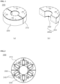
- FIG. 1 is a perspective view showing coupling and separating of a two-segment electromagnet stirring member according to an embodiment of the present disclosure.
- FIG. 2 is a top view showing the coupling of the two-segment electromagnet stirring member according to the embodiment of the present disclosure.
- FIG. 3 is a side view showing docking of a sleeve of a two-segment electromagnet semi-solid die-casting apparatus according to the embodiment of the present disclosure.
- FIG. 4 is a side view showing undocking of the sleeve of the two-segment electromagnet semi-solid die-casting apparatus according to the embodiment of the present disclosure.
- FIG. 1 is a perspective view showing coupling and separating of a two-segment electromagnet stirring member according to an embodiment of the present disclosure.
- FIG. 2 is a top view showing the coupling of the two-segment electromagnet stirring member according to the embodiment of the present disclosure.
- FIG. 3 is
- FIG. 5 is a sectional view showing stirring of molten metal of the two-segment electromagnet semi-solid die-casting apparatus according to the embodiment of the present disclosure.
- FIGS. 6 to 9 are sectional views showing a two-segment electromagnet semi-solid die-casting process according to an embodiment of the present disclosure.
- FIG. 10 is a process flowchart showing a two-segment electromagnet semi-solid die-casting method according to an embodiment of the present disclosure.
- a two-segment electromagnet stirring member 200 includes a plurality of magnetic field generation parts 230 therein and may be provided to be divided into a first electromagnetic stirring part 210 and a second electromagnetic stirring part 220.
- the first electromagnetic stirring part 210 and the second electromagnetic stirring part 220 are coupled to each other in a ring shape to surround an outer circumferential surface of the sleeve to perform electromagnetic stirring to the molten metal in the sleeve, and are coupled to each other to locate the magnetic field generation parts 230 at the radially equal gaps around the sleeve.
- a casing 200a of the two-segment electromagnet stirring member 200 may be provided.
- the casing 200a may be formed in a ring shape including an inner wall 202 into which a sleeve 310 of an injection member 300 is inserted and an outer wall 204 spaced apart from the inner wall 202.
- the casing 200a may have a structure in which all of upper and lower portions of regions between the inner wall and the outer wall and coupling surfaces of the first electromagnetic stirring part 210 and the second electromagnetic stirring part 220 are sealed, and the casing 200a may be formed of a non-magnetic material in order not to affect a magnetic field formed by the magnetic field generation parts 230.
- the periphery of the magnetic field generation parts 230 for example, a cooling passage hole 240 is located in an internal part of the outer wall 204 to provide a passage of a hose through which a coolant is moved, so that overheating of the magnetic field generation parts 230 may be prevented.
- the cooling passage hole 240 may serve as the passage through which a power cable providing power of the magnetic field generation parts 230 passes.
- Each of the magnetic field generation parts 230 includes a core and a coil wrapping the core, and the magnetic field generation parts 230 may be arranged at the radially equal gaps on the sleeve 310 as a center shaft, i.e., at the circumferentially equal gaps.
- Each of the magnetic field generation parts 230 is applied with a current clockwise or counterclockwise to generate a magnetic field, and by the magnetic field, molten metal A located in the sleeve 310 may be vibrated successively along a circumferential direction of the sleeve 310 so that a microstructure may be controlled.
- the two-segment electromagnet semi-solid die-casting apparatus 10 may include a mold member 100 including a movable mold 110 and a fixed mold 120, the injection member 300 including the sleeve 310 and a plunger 320 and injecting the molten metal into the mold member 100, and the two-segment electromagnet stirring member 200 including the first electromagnetic stirring part 210 located at one end of the movable mold 110 and moved in conjunction with the movable mold 110 and the second electromagnetic stirring part 220 located at one end of the fixed mold 120.
- the first electromagnetic stirring part 210 is moved to be coupled to the second electromagnetic stirring part 220 to surround the outer circumferential surface of the sleeve 310, and the two-segment electromagnet stirring member 200 performs electromagnetic stirring to the molten metal A located in the sleeve 310.
- the mold member 100 is closed in mold as shown in FIG. 1 , thereby having a cavity 130 in a shape of a product, and in order to eject a product B, the movable mold 110 is moved in a second direction, and thus the mold member 100 may be open in mold as shown in FIG. 2 .
- the two-segment electromagnet stirring member 200 includes the first electromagnetic stirring part 210 and the second electromagnetic stirring part 220, and the first electromagnetic stirring part 210 is located at a lower end of the movable mold 110 and is moved in a first or second direction together with the movable mold 110 in conjunction with the movable mold 110, thereby being coupled to or separated from the second electromagnetic stirring part 220 located at a lower end of the fixed mold 120.
- the two-segment electromagnet stirring member 200 may be coupled to or separated from each other separately from the injection member 300, so that maintenance can be easily performed and an injection process can be improved.
- the two-segment electromagnet stirring member 200 may include a cover part 240 to protect the first electromagnetic stirring part 210 and the second electromagnetic stirring part 220 from the outside space after ejection of the product from the mold member 100. Therefore, as shown in FIG. 9 , when the mold member 100 is open in mold to eject the product B, clean the movable mold 110 and the fixed mold 120, and coat a releasing agent, the cover part 240 is located outside the first electromagnetic stirring part 210 and the second electromagnetic stirring part 220 so as to protect the two-segment electromagnet stirring member 200 from a cleaning agent and the releasing agent.
- the two-segment electromagnet semi-solid die-casting apparatus 10 may include a product ejecting member (not shown) that ejects the product B manufactured from the mold member 100, and after ejection of the product B from the mold member 100, and may include a cleaning nozzle member 500 cleaning the fixed mold 120 and the movable mold 110.
- the cleaning nozzle member 500 may include a nozzle 520 spraying the cleaning agent and an arm 510 connected to the nozzle 520 and moving the nozzle 520 upward, downward, forward, and rearward.
- the injection member 300 may be rotated at a predetermined angle and the sleeve 310 may be tilted, and after the molten metal is injected into the tilted sleeve 310, as shown in FIG. 3 , the injection member may stand upright and then be inserted into the mold member through a lower end of the mold member 100.
- a rotation support shaft 340 may be provided at a lower end of the injection member 300, and a rotating driving cylinder 350 may be provided at one side portion of the injection member 300.
- the injection member 300 is rotated at the predetermined angle on the rotation support shaft 340 and the sleeve 310 may be tilted at a predetermined angle, and the molten metal A may be injected into the tilted sleeve 310.
- the cylinder rod 350a is contracted and the sleeve 310 stands upright together with the injection member 300 and may be inserted into the mold member 100 through the lower end of the mold member 100.
- the movable mold 110 is moved the first direction, the movable mold 110 is coupled to the fixed mold 120, the mold member 100 is closed in mold and the cavity 130 is provided in a shape of a product, and simultaneously, as the first electromagnetic stirring part 210 is moved in the first direction in conjunction with the movable mold 110, and the first electromagnetic stirring part 210 may be coupled to the second electromagnetic stirring part 220.
- the sleeve 310 is inserted into the mold member 100 through the lower end of the mold member 100 and the sleeve 310 may be docked to the mold member 100 while being coupled to the mold member 100 such that the inner wall 202 of the two-segment electromagnet stirring member 200 surrounds the outer circumferential surface of the sleeve 310, and the two-segment electromagnet stirring member 200 may perform electromagnetic stirring to the molten metal A located in the sleeve 310.
- the injection member 300 includes a coupling-type sleeve removing tool (not shown) located at one end of an injection rod 360, and as the sleeve removing tool pushes the sleeve 310 upwards, the sleeve 310 may be uncoupled from the injection member 300. Therefore, during the injection process, even when defects or damages occur to the sleeve 310, it is possible to efficiently replace the sleeve 310 with the sleeve removing tool, which is an advantage. Furthermore, regardless of the replacement process of the sleeve 310, the two-segment electromagnet stirring member 200 is provided separately from the injection member 300, so that maintenance can be easily performed and an injection process can be improved.
- the two-segment electromagnet semi-solid die-casting apparatus 10 may include a sleeve releasing jig (not shown) located at an upper portion of the injection member 300, and as the sleeve 310 pushed upwards by the sleeve removing tool and the sleeve releasing jig are coupled to each other, the sleeve 310 may be separated from the injection member 300. Therefore, the sleeve replacement operation can be efficiently performed.
- a two-segment electromagnet semi-solid die-casting method includes injecting the molten metal A into the sleeve 310 of the injection member 300 first, at S110.
- the injecting the molten metal into the sleeve 310 by the injection member may be performed by rotating the injection member 300 at the predetermined angle to tilt the sleeve 310 (a), and injecting the molten metal A into the tilted sleeve 310 (b), and then making the injection member stand upright (c).
- the rotating driving cylinder 350 provided at one portion of the injection member 300 is operated to extend the cylinder rod 350a
- the injection member 300 is rotated at the predetermined angle on the rotation support shaft 340 provided at the lower end of the injection member 300, so that the sleeve 310 may be tilted at the predetermined angle.
- the cylinder rod 350a is contracted and the sleeve 310 may stand upright together with the injection member 300.
- the movable mold 110 of the mold member 100 is moved in the first direction to be coupled to the fixed mold 120 to be closed in mold (c), and the first electromagnetic stirring part 210 located at one end of the movable mold 110 is moved in conjunction with the movable mold 110 and may be coupled to the second electromagnetic stirring part 220 located at one end of the fixed mold 120, at S120.
- the injecting of the molten metal into the sleeve 310 at S110 and the coupling of the mold member 100 and the two-segment electromagnet stirring member 200 at S120 may be performed simultaneously, as shown in FIG. 6 .
- the coupling of the first electromagnetic stirring part 210 and the second electromagnetic stirring part 220 may be performed such that the plurality of magnetic field generation parts 230 is located at the radially equal gaps around the sleeve 310.
- the first electromagnetic stirring part 210 may be coupled to the second electromagnetic stirring part 220 to form the ring-shaped two-segment electromagnet stirring member 200 having a hollow portion.
- the two-segment electromagnet stirring member 200 may have the casing 200a as the first electromagnetic stirring part 210 and the second electromagnetic stirring part 220 are coupled to each other.
- the casing 200a may be formed in a ring shape including the inner wall 202 into which the sleeve 310 of the injection member is inserted and the outer wall 204 spaced apart from the inner wall 202. Furthermore, in order to protect the plurality of magnetic field generation parts 230 located inside the casing 200a from the outside space, the casing 200a may be formed such that the first electromagnetic stirring part 210 and the second electromagnetic stirring part 220 may be coupled to each other so as to seal the magnetic field generation parts 230.
- the sleeve 310 is inserted into the mold member 100 through the lower portion of the mold member 100 while passing through the hollow portion of the two-segment electromagnet stirring member 200, and the two-segment electromagnet stirring member 200 located to surround the outer circumferential surface of the sleeve 310 may perform electromagnet stirring with respect to the molten metal at S130.
- the two-segment electromagnet stirring member 200 may start generating electromagnetism (d).
- each of the magnetic field generation parts is applied with a current clockwise or counterclockwise to generate a magnetic field, and the molten metal A located in the sleeve 310 is vibrated in a circumferential direction of the sleeve 310 sequentially by the magnetic field so that the microstructure of the molten metal A.
- the magnetic flux of the magnetic field formed by the magnetic field generation parts exerts an impact on the inside portion of the molten metal, and a part of the molten metal is vibrated vertically, so that vertical intermittent vibration stirring may be performed without stirring such as rotating. Therefore, without rotation accompanied by turbulence of the semi-solid molten metal, vibration movement accompanied by shaking of the molten metal is generated, so that intermittent vibration of the molten metal generated by the magnetic field impact may inhibit generation of dendrite, and the microstructure is controlled, thereby preventing the outside air that may be introduced when rotational stirring is performed by the electromagnetic field.
- the plunger 320 is moved the electromagnetic-stirred molten metal A may be injected into the mold member 100 (e) and may be pressurized (f) at S140.
- the plunger 320 may inject the molten metal A into the cavity 130 of the mold member 100 (e), and the two-segment electromagnet stirring member 200 may maintain magnetic field generation until injection into the cavity 130 is completed.
- electromagnetism generation of the two-segment electromagnet stirring member 200 may be completed.
- the mold member 100 is open in mold and the product B may be ejected from the mold member 100 at S140.
- the plunger 320 is lowered, and the injection member 300 may be undocked from the mold member 100 (g).
- the movable mold 110 is separated from the fixed mold 120 so that the mold member 100 may be open in mold (h), and the first electromagnetic stirring part 210 is also separated from the second electromagnetic stirring part 220 in conjunction with movement of the movable mold 110, and may be moved in the second direction together with the movable mold 110.
- the injection member 300 may be tilted at the predetermined angle (i).
- the product ejecting member located at one side portion of the mold member is operated and the product may be ejected (j), and the movable mold and the fixed mold may be cleaned (k), and the releasing agent may be coated at S160.
- the method may include moving the cover part 240 to the outside space of the first electromagnetic stirring part 210 and the second electromagnetic stirring part 220 to protect the two-segment electromagnet stirring member 200 at S150.
- the cover part 240 is moved, so that the outside space of the two-segment electromagnet stirring member 200 may be protected.
- the cleaning nozzle member 500 is provided above the mold member 100, so that after the product is ejected from the mold member 100, cavity regions of the fixed mold 120 and the movable mold 110 may be cleaned.
- the method may include cleaning the tilted sleeve 310 by using a sleeve cleaning member 600.
- the two-segment electromagnet semi-solid die-casting apparatus and the die-casting method using the same can have the advantage of controlling the structure of the molten metal while preventing impacts and damages to the two-segment electromagnet stirring member 200 during docking and undocking of the sleeve 310 with respect to the mold member 100 and efficiently providing electromagnetic vibration into the molten metal A in the sleeve 310.
- the two-segment electromagnet stirring member 200 can be coupled to or uncoupled from each other, so that the injection process can be improved.
Landscapes
- Engineering & Computer Science (AREA)
- Mechanical Engineering (AREA)
- Chemical & Material Sciences (AREA)
- Chemical Kinetics & Catalysis (AREA)
- General Engineering & Computer Science (AREA)
- Continuous Casting (AREA)
- Physical Or Chemical Processes And Apparatus (AREA)
Description
- The present invention relates to a two-segment electromagnet semi-solid die-casting apparatus and a die-casting method using the same. The present invention relates to a two-segment electromagnet semi-solid die-casting apparatus and a die-casting method using the same, which are configured such that a two-segment electromagnet stirring member is movable and couplable in conjunction with movement of a mold and electromagnetic vibration is applied into molten metal in a sleeve to control the structure of the molten metal.
- A semi-solid metal material exists a state in which liquid phase and spherical crystal grains are mixed in an appropriate ratio in a semi-solid temperature range, and may refer to as a metal material that can be deformed even with a small force due to a thixotropic property and have excellent fluidity so as to be easy to be processed by molding like a liquid phase. Since the semi-solid metal material generally has fluidity at a lower temperature than liquid metal, the temperature of an exposed casting equipment can be lowered than the temperature of the liquid metal, and thus the life of the casting equipment can extend. In addition, when the semi-solid metal material is extruded, since turbulence thereof is less generated than in the liquid state, the mixing of air during casting can be reduced, and with a semi-solid state, contraction during solidification is small. As a result, workability is improved, and a product can be reduced in weight, so that the semi-solid metal material can be applied to a new material molding field.
- As one of the casting methods that can use a semi-solid metal material, semi-solid die-casting is a casting method in which molten metal is pressed into a mold having a predetermined hollow part shape and casted by being pressurized until the molten metal is solidified. As a representative example of the semi-solid die-casting, there is a horizontal die clamping vertical shot squeeze casting (HVSC) method in which a sleeve injected with molten metal is inserted through a lower part of the mold.
- As a method of performing structure control of the semi-solid molten metal by applying electromagnetic stirring to the above-described semi-solid die-casting apparatus to generate an electromagnetic field into the molten metal, the technique in which an electromagnetic induction coil is provided on an outer circumferential surface of a sleeve has been disclosed in
Japanese Patent Application Publication No. 11-245012 - However, when the electromagnetic induction coil is provided on the outer circumferential surface of the sleeve and the sleeve is docked to the mold, a portion or more of the electromagnetic induction coil is inserted into the mold, and the electromagnetic induction coil may be damaged by the mold during the process. As such, a problem may occur with electromagnetic application for controlling the structure of the molten metal, which may affect the quality of castings. In addition, since the electromagnetic induction coil should be replaced for each replacement of the sleeve, a problem of increasing process cost may occur.
- Conventional electromagnetic stirring members are disclosed in
US 2006/124272 A1 ,JP H07 108355 A JP H06 23498 A CN 110 514 010 AKR 2011 0102661 A -
- (Patent Document 0001)
Japan Patent Application Publication No. 11-245012 (Date of Publication: September 14, 1999 - (Patent Document 0002)
Korean Patent No. 10-0690058 (Date of Registration: February 26, 2007 - Accordingly, the present disclosure has been made keeping in mind the above problems occurring in the related art, and the present disclosure is intended to propose a two-segment electromagnet semi-solid die-casting apparatus and a die-casting method using the same, which are configured to prevent impacts and damages to a two-segment electromagnet stirring member during coupling and separating of a sleeve and a mold and to efficiently provide electromagnetic vibrations to molten metal in the sleeve to control the structure of the molten metal.
- Another objective of the present disclosure is to provide a two-segment electromagnet semi-solid die-casting apparatus and a die-casting method using the same, which are configured to improve an injection process by providing a two-segment electromagnet stirring member which is operated in conjunction with a movable mold and a fixed mold, regardless of replacement of a sleeve.
- The objective of the present disclosure is not limited to the above-described objectives, and other objectives of the present disclosure not mentioned will be clearly understood by those skilled in the art from the subsequent description.
- The present invention is directed to subject matter as defined in the appended set of claims. The scope of the present invention is defined by
independent claims 1 and 4, and further embodiments of the invention are specified in dependent claims 2, 3 and 5-7. - The description that follows is subjected to this limitation. Any disclosure lying outside the scope of said claims is only intended for illustrative as well as comparative purposes.
- According to the embodiment of the present disclosure, the two-segment electromagnet semi-solid die-casting apparatus and the die-casting method using the same can prevent impacts and damages to the two-segment electromagnet stirring member when the sleeve is coupled to and separated from the mold member and can efficiently provide electromagnetic vibrations into the molten metal located in the sleeve to control the structure of the molten metal.
- Furthermore, the first electromagnetic stirring part and the second electromagnetic stirring part are respectively located at the lower portions of the movable mold and the fixed mold and thus the two-segment electromagnet stirring member operated in conjunction with mold closure and mold opening of the movable mold and the fixed mold. Accordingly, the two-segment electromagnet stirring member can be coupled to or separated from each other regardless of replacement of the sleeve, so that maintenance can be easily performed and the injection process can be improved.
-
-
FIG. 1 is a perspective view showing coupling and separating of a two-segment electromagnet stirring member according to an embodiment of the present disclosure, -
FIG. 2 is a top view showing the coupling of the two-segment electromagnet stirring member according to the embodiment of the present disclosure, -
FIG. 3 is a side view showing docking of a sleeve of a two-segment electromagnet semi-solid die-casting apparatus according to the embodiment of the present disclosure, -
FIG. 4 is a side view showing undocking of the sleeve of the two-segment electromagnet semi-solid die-casting apparatus according to the embodiment of the present disclosure, -
FIG. 5 is a sectional view showing stirring of molten metal of the two-segment electromagnet semi-solid die-casting apparatus according to the embodiment of the present disclosure, -
FIGS. 6 to 9 are sectional views showing a two-segment electromagnet semi-solid die-casting process according to an embodiment of the present disclosure, and -
FIG. 10 is a process flowchart showing a two-segment electromagnet semi-solid die-casting method according to an embodiment of the present disclosure. - Hereinbelow, exemplary embodiments of the present disclosure will be described in detail with reference to accompanying drawings. Therefore, the present disclosure is not limited to the embodiments described below and may be embodied in other forms. Furthermore, in the drawings, lengths, thicknesses, etc. of layers and regions may be exaggerated for convenience description. Throughout the specification, the same reference numerals will refer to the same or like parts.
-
FIG. 1 is a perspective view showing coupling and separating of a two-segment electromagnet stirring member according to an embodiment of the present disclosure.FIG. 2 is a top view showing the coupling of the two-segment electromagnet stirring member according to the embodiment of the present disclosure.FIG. 3 is a side view showing docking of a sleeve of a two-segment electromagnet semi-solid die-casting apparatus according to the embodiment of the present disclosure.FIG. 4 is a side view showing undocking of the sleeve of the two-segment electromagnet semi-solid die-casting apparatus according to the embodiment of the present disclosure.FIG. 5 is a sectional view showing stirring of molten metal of the two-segment electromagnet semi-solid die-casting apparatus according to the embodiment of the present disclosure.FIGS. 6 to 9 are sectional views showing a two-segment electromagnet semi-solid die-casting process according to an embodiment of the present disclosure.FIG. 10 is a process flowchart showing a two-segment electromagnet semi-solid die-casting method according to an embodiment of the present disclosure. - Referring to
FIGS. 1 to 5 , according to an embodiment of the present disclosure, a two-segmentelectromagnet stirring member 200 includes a plurality of magneticfield generation parts 230 therein and may be provided to be divided into a first electromagnetic stirringpart 210 and a second electromagnetic stirringpart 220. The first electromagnetic stirringpart 210 and the secondelectromagnetic stirring part 220 are coupled to each other in a ring shape to surround an outer circumferential surface of the sleeve to perform electromagnetic stirring to the molten metal in the sleeve, and are coupled to each other to locate the magneticfield generation parts 230 at the radially equal gaps around the sleeve. - As the first electromagnetic stirring
part 210 and the second electromagnetic stirringpart 220 of the ring-shaped two-segmentelectromagnet stirring member 200 having a hollow portion at the center portion are coupled to each other, acasing 200a of the two-segmentelectromagnet stirring member 200 may be provided. Thecasing 200a may be formed in a ring shape including aninner wall 202 into which asleeve 310 of aninjection member 300 is inserted and anouter wall 204 spaced apart from theinner wall 202. Furthermore, in order to protect the plurality of magneticfield generation parts 230 located in thecasing 200a from the outside space, thecasing 200a may have a structure in which all of upper and lower portions of regions between the inner wall and the outer wall and coupling surfaces of the first electromagnetic stirringpart 210 and the second electromagneticstirring part 220 are sealed, and thecasing 200a may be formed of a non-magnetic material in order not to affect a magnetic field formed by the magneticfield generation parts 230. Moreover, the periphery of the magneticfield generation parts 230, for example, acooling passage hole 240 is located in an internal part of theouter wall 204 to provide a passage of a hose through which a coolant is moved, so that overheating of the magneticfield generation parts 230 may be prevented. In some cases, thecooling passage hole 240 may serve as the passage through which a power cable providing power of the magneticfield generation parts 230 passes. - Each of the magnetic
field generation parts 230 includes a core and a coil wrapping the core, and the magneticfield generation parts 230 may be arranged at the radially equal gaps on thesleeve 310 as a center shaft, i.e., at the circumferentially equal gaps. Each of the magneticfield generation parts 230 is applied with a current clockwise or counterclockwise to generate a magnetic field, and by the magnetic field, molten metal A located in thesleeve 310 may be vibrated successively along a circumferential direction of thesleeve 310 so that a microstructure may be controlled. In other words, when a magnetic flux of the magnetic field formed through the magneticfield generation parts 230 exerts an impact on the inside portion of the molten metal A, a part of the molten metal A is vibrated vertically and thus vertical intermittent vibration stirring may be performed without stirring such as rotating. Therefore, without rotation movement accompanied by turbulence of the molten metal, vibration movement accompanied by shaking of the molten metal is generated, so that intermittent vibration of the molten metal generated by the magnetic field impact may inhibit generation of dendrite, and the microstructure is controlled, thereby preventing the outside air that may be introduced when rotational stirring is performed by the electromagnetic field. - Referring to
FIGS. 1 to 9 , the two-segment electromagnet semi-solid die-casting apparatus 10 may include amold member 100 including amovable mold 110 and a fixedmold 120, theinjection member 300 including thesleeve 310 and aplunger 320 and injecting the molten metal into themold member 100, and the two-segmentelectromagnet stirring member 200 including the first electromagnetic stirringpart 210 located at one end of themovable mold 110 and moved in conjunction with themovable mold 110 and the second electromagnetic stirringpart 220 located at one end of the fixedmold 120. As themovable mold 110 is moved, the first electromagneticstirring part 210 is moved to be coupled to the secondelectromagnetic stirring part 220 to surround the outer circumferential surface of thesleeve 310, and the two-segmentelectromagnet stirring member 200 performs electromagnetic stirring to the molten metal A located in thesleeve 310. - When describing the structure in detail, as the
movable mold 110 is moved in a first direction toward the fixedmold 120, themold member 100 is closed in mold as shown inFIG. 1 , thereby having acavity 130 in a shape of a product, and in order to eject a product B, themovable mold 110 is moved in a second direction, and thus themold member 100 may be open in mold as shown inFIG. 2 . - As shown in
FIGS. 1 and 2 , the two-segmentelectromagnet stirring member 200 includes the first electromagnetic stirringpart 210 and the second electromagnetic stirringpart 220, and the first electromagnetic stirringpart 210 is located at a lower end of themovable mold 110 and is moved in a first or second direction together with themovable mold 110 in conjunction with themovable mold 110, thereby being coupled to or separated from the second electromagnetic stirringpart 220 located at a lower end of the fixedmold 120. Therefore, as the first electromagnetic stirringpart 210 and the second electromagnetic stirringpart 220 are respectively located at the lower ends of themovable mold 110 and the fixedmold 120 to provide the two-segmentelectromagnet stirring member 200 that is coupled to or separated from each other in conjunction with mold closure or mold opening of themovable mold 110 and the fixedmold 120, regardless of replacement of thesleeve 310, the two-segmentelectromagnet stirring member 200 may be coupled to or separated from each other separately from theinjection member 300, so that maintenance can be easily performed and an injection process can be improved. - The two-segment
electromagnet stirring member 200 may include acover part 240 to protect the first electromagnetic stirringpart 210 and the second electromagnetic stirringpart 220 from the outside space after ejection of the product from themold member 100. Therefore, as shown inFIG. 9 , when themold member 100 is open in mold to eject the product B, clean themovable mold 110 and the fixedmold 120, and coat a releasing agent, thecover part 240 is located outside the first electromagnetic stirringpart 210 and the second electromagnetic stirringpart 220 so as to protect the two-segmentelectromagnet stirring member 200 from a cleaning agent and the releasing agent. - At this point, the two-segment electromagnet semi-solid die-casting
apparatus 10 may include a product ejecting member (not shown) that ejects the product B manufactured from themold member 100, and after ejection of the product B from themold member 100, and may include acleaning nozzle member 500 cleaning the fixedmold 120 and themovable mold 110. For example, the cleaningnozzle member 500 may include anozzle 520 spraying the cleaning agent and anarm 510 connected to thenozzle 520 and moving thenozzle 520 upward, downward, forward, and rearward. - As shown in
FIG. 4 , theinjection member 300 may be rotated at a predetermined angle and thesleeve 310 may be tilted, and after the molten metal is injected into the tiltedsleeve 310, as shown inFIG. 3 , the injection member may stand upright and then be inserted into the mold member through a lower end of themold member 100. For example, arotation support shaft 340 may be provided at a lower end of theinjection member 300, and arotating driving cylinder 350 may be provided at one side portion of theinjection member 300. When therotating driving cylinder 350 is operated to allow acylinder rod 350a to extend, theinjection member 300 is rotated at the predetermined angle on therotation support shaft 340 and thesleeve 310 may be tilted at a predetermined angle, and the molten metal A may be injected into the tiltedsleeve 310. When injecting of the molten metal A is completed, thecylinder rod 350a is contracted and thesleeve 310 stands upright together with theinjection member 300 and may be inserted into themold member 100 through the lower end of themold member 100. In other words, as themovable mold 110 is moved the first direction, themovable mold 110 is coupled to the fixedmold 120, themold member 100 is closed in mold and thecavity 130 is provided in a shape of a product, and simultaneously, as the first electromagnetic stirringpart 210 is moved in the first direction in conjunction with themovable mold 110, and the first electromagnetic stirringpart 210 may be coupled to the second electromagnetic stirringpart 220. At this point, thesleeve 310 is inserted into themold member 100 through the lower end of themold member 100 and thesleeve 310 may be docked to themold member 100 while being coupled to themold member 100 such that theinner wall 202 of the two-segmentelectromagnet stirring member 200 surrounds the outer circumferential surface of thesleeve 310, and the two-segmentelectromagnet stirring member 200 may perform electromagnetic stirring to the molten metal A located in thesleeve 310. Therefore, when thesleeve 310 is docked or undocked with respect to themold member 100, impacts and damages to the two-segmentelectromagnet stirring member 200 can be prevented, and as such, electromagnetic vibration is efficiently provided into the molten metal A located in thesleeve 310, so that improved quality of the molded product B can be maintained constant by controlling the structure of the molten metal A. - The
injection member 300 includes a coupling-type sleeve removing tool (not shown) located at one end of aninjection rod 360, and as the sleeve removing tool pushes thesleeve 310 upwards, thesleeve 310 may be uncoupled from theinjection member 300. Therefore, during the injection process, even when defects or damages occur to thesleeve 310, it is possible to efficiently replace thesleeve 310 with the sleeve removing tool, which is an advantage. Furthermore, regardless of the replacement process of thesleeve 310, the two-segmentelectromagnet stirring member 200 is provided separately from theinjection member 300, so that maintenance can be easily performed and an injection process can be improved. - Moreover, the two-segment electromagnet semi-solid die-casting
apparatus 10 may include a sleeve releasing jig (not shown) located at an upper portion of theinjection member 300, and as thesleeve 310 pushed upwards by the sleeve removing tool and the sleeve releasing jig are coupled to each other, thesleeve 310 may be separated from theinjection member 300. Therefore, the sleeve replacement operation can be efficiently performed. - Referring to
FIGS. 6 to 10 , according to the embodiment of the present disclosure, a two-segment electromagnet semi-solid die-casting method includes injecting the molten metal A into thesleeve 310 of theinjection member 300 first, at S110. The injecting the molten metal into thesleeve 310 by the injection member may be performed by rotating theinjection member 300 at the predetermined angle to tilt the sleeve 310 (a), and injecting the molten metal A into the tilted sleeve 310 (b), and then making the injection member stand upright (c). For example, when therotating driving cylinder 350 provided at one portion of theinjection member 300 is operated to extend thecylinder rod 350a, theinjection member 300 is rotated at the predetermined angle on therotation support shaft 340 provided at the lower end of theinjection member 300, so that thesleeve 310 may be tilted at the predetermined angle. After then, when the molten metal A is injected into the tiltedsleeve 310 and injection of the molten metal A is completed, thecylinder rod 350a is contracted and thesleeve 310 may stand upright together with theinjection member 300. - Next, the
movable mold 110 of themold member 100 is moved in the first direction to be coupled to the fixedmold 120 to be closed in mold (c), and the first electromagnetic stirringpart 210 located at one end of themovable mold 110 is moved in conjunction with themovable mold 110 and may be coupled to the second electromagnetic stirringpart 220 located at one end of the fixedmold 120, at S120. At this point, the injecting of the molten metal into thesleeve 310 at S110 and the coupling of themold member 100 and the two-segmentelectromagnet stirring member 200 at S120 may be performed simultaneously, as shown inFIG. 6 . - The coupling of the first electromagnetic stirring
part 210 and the second electromagnetic stirringpart 220 may be performed such that the plurality of magneticfield generation parts 230 is located at the radially equal gaps around thesleeve 310. The first electromagnetic stirringpart 210 may be coupled to the second electromagnetic stirringpart 220 to form the ring-shaped two-segmentelectromagnet stirring member 200 having a hollow portion. At this point, the two-segmentelectromagnet stirring member 200 may have thecasing 200a as the first electromagnetic stirringpart 210 and the second electromagnetic stirringpart 220 are coupled to each other. Thecasing 200a may be formed in a ring shape including theinner wall 202 into which thesleeve 310 of the injection member is inserted and theouter wall 204 spaced apart from theinner wall 202. Furthermore, in order to protect the plurality of magneticfield generation parts 230 located inside thecasing 200a from the outside space, thecasing 200a may be formed such that the first electromagnetic stirringpart 210 and the second electromagnetic stirringpart 220 may be coupled to each other so as to seal the magneticfield generation parts 230. - Next, the
sleeve 310 is inserted into themold member 100 through the lower portion of themold member 100 while passing through the hollow portion of the two-segmentelectromagnet stirring member 200, and the two-segmentelectromagnet stirring member 200 located to surround the outer circumferential surface of thesleeve 310 may perform electromagnet stirring with respect to the molten metal at S130. In other words, when thesleeve 310 passes through the hollow portion formed by theinner wall 202 of the casing and is inserted into themold member 100, the two-segmentelectromagnet stirring member 200 may start generating electromagnetism (d). In the magneticfield generation parts 230 arranged at the radially equal gaps on thesleeve 310 as the center shaft, i.e., arranged at circumferentially equal intervals, each of the magnetic field generation parts is applied with a current clockwise or counterclockwise to generate a magnetic field, and the molten metal A located in thesleeve 310 is vibrated in a circumferential direction of thesleeve 310 sequentially by the magnetic field so that the microstructure of the molten metal A. In other words, the magnetic flux of the magnetic field formed by the magnetic field generation parts exerts an impact on the inside portion of the molten metal, and a part of the molten metal is vibrated vertically, so that vertical intermittent vibration stirring may be performed without stirring such as rotating. Therefore, without rotation accompanied by turbulence of the semi-solid molten metal, vibration movement accompanied by shaking of the molten metal is generated, so that intermittent vibration of the molten metal generated by the magnetic field impact may inhibit generation of dendrite, and the microstructure is controlled, thereby preventing the outside air that may be introduced when rotational stirring is performed by the electromagnetic field. - Next, the
plunger 320 is moved the electromagnetic-stirred molten metal A may be injected into the mold member 100 (e) and may be pressurized (f) at S140. In other words, as theinjection rod 360 is raised and thus the plunger rod coupled to an end of theinjection rod 360 is raised, theplunger 320 may inject the molten metal A into thecavity 130 of the mold member 100 (e), and the two-segmentelectromagnet stirring member 200 may maintain magnetic field generation until injection into thecavity 130 is completed. When pressuring the molten metal into themold member 100 starts with completion of upward movement of the plunger 320 (f), electromagnetism generation of the two-segmentelectromagnet stirring member 200 may be completed. - Next, the
mold member 100 is open in mold and the product B may be ejected from themold member 100 at S140. When formation of the product is completed, theplunger 320 is lowered, and theinjection member 300 may be undocked from the mold member 100 (g). After then, as themovable mold 110 is moved in the second direction, themovable mold 110 is separated from the fixedmold 120 so that themold member 100 may be open in mold (h), and the first electromagnetic stirringpart 210 is also separated from the second electromagnetic stirringpart 220 in conjunction with movement of themovable mold 110, and may be moved in the second direction together with themovable mold 110. Furthermore, theinjection member 300 may be tilted at the predetermined angle (i). - After then, the product ejecting member located at one side portion of the mold member is operated and the product may be ejected (j), and the movable mold and the fixed mold may be cleaned (k), and the releasing agent may be coated at S160.
- After the ejecting of the product B, before the cleaning of the
mold member 100, the method may include moving thecover part 240 to the outside space of the first electromagnetic stirringpart 210 and the second electromagnetic stirringpart 220 to protect the two-segmentelectromagnet stirring member 200 at S150. In order to prevent the cleaning agent sprayed during cleaning of themold member 100 and a chemical sprayed during coating of the releasing agent to affect the two-segmentelectromagnet stirring member 200, before themold member 100 is cleaned (k), thecover part 240 is moved, so that the outside space of the two-segmentelectromagnet stirring member 200 may be protected. - Furthermore, the cleaning
nozzle member 500 is provided above themold member 100, so that after the product is ejected from themold member 100, cavity regions of the fixedmold 120 and themovable mold 110 may be cleaned. In this case, the method may include cleaning the tiltedsleeve 310 by using asleeve cleaning member 600. - According to the embodiment of the present disclosure, the two-segment electromagnet semi-solid die-casting apparatus and the die-casting method using the same can have the advantage of controlling the structure of the molten metal while preventing impacts and damages to the two-segment
electromagnet stirring member 200 during docking and undocking of thesleeve 310 with respect to themold member 100 and efficiently providing electromagnetic vibration into the molten metal A in thesleeve 310. - Furthermore, as the first electromagnetic stirring
part 210 and the second electromagnetic stirringpart 220 are respectively located at the lower portions of themovable mold 110 and the fixedmold 120 and the two-segmentelectromagnet stirring member 200 operated in conjunction with mold closure and mold opening of themovable mold 110 and the fixedmold 120 is provided, regardless of replacement of thesleeve 310, the two-segmentelectromagnet stirring member 200 can be coupled to or uncoupled from each other, so that the injection process can be improved. - It should be noted that the embodiments of the present disclosure is for the explanation of the present disclosure, and not for the limitation of the present invention. The scope of the present invention is defined in the appended claims.
-
- 10: two-segment electromagnet semi-solid die-casting apparatus
- 100: mold member
- 110: movable mold
- 120: fixed mold
- 130: cavity
- 200: two-segment electromagnet stirring member
- 200a: casing
- 202: inner wall
- 204: outer wall
- 210: first electromagnetic stirring part
- 220: second electromagnetic stirring part
- 230: magnetic field generation units
- 240: cover part
- 300: injection member
- 310: sleeve
- 320: plunger
- 340: rotation support shaft
- 350: driving cylinder
- 360: injection rod
- 500: cleaning nozzle member
- 600: sleeve cleaning member
- A: molten metal
- B: product.
Claims (7)
- A two-segment electromagnet semi-solid die-casting apparatus (10) comprising:a mold member (100) comprising a movable mold (110) and a fixed mold (120);an injection member (300) comprising a sleeve (310) and a plunger (320) and configured to inject molten metal (A) into the mold member (100); anda two-segment electromagnet stirring member (200) comprising a first electromagnetic stirring part (210) and a second electromagnetic stirring part (220), the first electromagnetic stirring part (210) being located at one end of the movable mold (110) and being configured to be moved in conjunction with the movable mold (110) and the second electromagnetic stirring part (220) being located at one end of the fixed mold (120),wherein the first electromagnetic stirring part (210) is configured to be moved with movement of the movable mold (110) to be coupled to the second electromagnetic stirring part (220) to surround an outer circumferential surface of the sleeve (310), and the two-segment electromagnet stirring member (200) is configured to perform electromagnetic stirring to the molten metal (A) located in the sleeve (310).
- The two-segment electromagnet semi-solid die-casting apparatus (10) of claim 1, wherein the two-segment electromagnet stirring member (200) comprises a cover part (240), the cover part (240) being configured to protect the first electromagnetic stirring part (210) and the second electromagnetic stirring part (220) from outside space after a product (B) is ejected from the mold member (100).
- The two-segment electromagnet semi-solid die-casting apparatus (10) of claim 1, wherein the injection member (300) is configured to rotate at a predetermined angle and thus the sleeve (310) is tiltable, and after the molten metal is injected into the tilted sleeve, the injection member (300) is configured to stand upright and insert into the mold member (100) through a lower end of the mold member (100).
- A two-segment electromagnet semi-solid die-casting method comprising:injecting molten metal (A) into a sleeve (310) of an injection member (300);moving and coupling a movable mold (110) of a mold member (100) to a fixed mold (120), and allowing a first electromagnetic stirring part (210) located at one end of the movable mold (110) to be moved in conjunction with the movable mold (110) to couple the first electromagnetic stirring part (210) to a second electromagnetic stirring part (220) located at one end of the fixed mold (120), thereby forming a ring-shaped two-segment electromagnet stirring member (200) having a hollow portion;inserting the sleeve (310) into the mold member (100) through a lower portion of the mold member (100) while passing through the hollow portion of the two-segment electromagnet stirring member (200), and allowing the two-segment electromagnet stirring member (200) located to surround an outer circumferential surface of the sleeve (310) to perform electromagnetic stirring to the molten metal (A); andinjecting the electromagnetic stirred molten metal (A) into the mold member (100) as a plunger (320) is moved.
- The two-segment electromagnet semi-solid die-casting method of claim 4, wherein the coupling of the first electromagnetic stirring part (210) and the second electromagnetic stirring part (220) is performed by positioning a plurality of magnetic field generation parts (230) at radially equal gaps around the sleeve (310).
- The two-segment electromagnet semi-solid die-casting method of claim 4, wherein the two-segment electromagnet semi-solid die-casting method comprises:ejecting a product (B) from the mold member (100) and cleaning the movable mold (110) and the fixed mold (120), and coating a releasing agent,wherein before the cleaning of the movable mold (110) and the fixed mold (120) or the coating with the releasing agent, the method comprises: moving a cover part (240) to outside space of the first electromagnetic stirring part (210) and the second electromagnetic stirring part (220) to protect the two-segment electromagnet stirring member (200).
- The two-segment electromagnet semi-solid die-casting method of claim 4, wherein the injecting of the molten metal (A) into the sleeve (310) of the injection member (300) is performed by rotating the injection member (300) at a predetermined angle to tilt the sleeve (310), and injecting the molten metal (A) into the tilted sleeve (310) and then allowing the injection member (300) to stand upright.
Applications Claiming Priority (2)
| Application Number | Priority Date | Filing Date | Title |
|---|---|---|---|
| KR1020210000191A KR102440267B1 (en) | 2021-01-04 | 2021-01-04 | Two-segment electromagnet reaction reactor diecasting apparatus and diecasting method using the same |
| PCT/KR2021/019603 WO2022145862A1 (en) | 2021-01-04 | 2021-12-22 | Two-part electromagnet semi-solidification die-casting device and manufacturing method using same |
Publications (4)
| Publication Number | Publication Date |
|---|---|
| EP4245437A1 EP4245437A1 (en) | 2023-09-20 |
| EP4245437A4 EP4245437A4 (en) | 2024-04-10 |
| EP4245437B1 true EP4245437B1 (en) | 2024-11-06 |
| EP4245437C0 EP4245437C0 (en) | 2024-11-06 |
Family
ID=82259467
Family Applications (1)
| Application Number | Title | Priority Date | Filing Date |
|---|---|---|---|
| EP21915660.1A Active EP4245437B1 (en) | 2021-01-04 | 2021-12-22 | Two-part electromagnet semi-solidification die-casting device and manufacturing method using same |
Country Status (4)
| Country | Link |
|---|---|
| US (1) | US11931798B2 (en) |
| EP (1) | EP4245437B1 (en) |
| KR (1) | KR102440267B1 (en) |
| WO (1) | WO2022145862A1 (en) |
Citations (1)
| Publication number | Priority date | Publication date | Assignee | Title |
|---|---|---|---|---|
| KR20110102661A (en) * | 2010-03-11 | 2011-09-19 | 주식회사 퓨쳐캐스트 | Die Casting Apparatus and Die Casting Method |
Family Cites Families (14)
| Publication number | Priority date | Publication date | Assignee | Title |
|---|---|---|---|---|
| JP2755038B2 (en) * | 1992-05-11 | 1998-05-20 | 住友金属工業株式会社 | Continuous casting method with electromagnetic stirring |
| JPH0623498A (en) * | 1992-07-10 | 1994-02-01 | Sumitomo Heavy Ind Ltd | Device for controlling supply of molten steel in continuous casting |
| JPH07108355A (en) * | 1993-10-08 | 1995-04-25 | Kobe Steel Ltd | Electromagnetic stirrer |
| JPH11245012A (en) | 1998-02-27 | 1999-09-14 | Nissan Motor Co Ltd | Method and apparatus for producing semi-solid material |
| FR2856321B1 (en) * | 2003-06-17 | 2006-05-26 | Usinor | CONTINUOUS CASTING INSTALLATION FOR ELECTRO-MAGNETIC ROTATION OF LIQUID METAL IN TRANSIT IN THE CASTING BUSH |
| KR20050064741A (en) * | 2003-12-24 | 2005-06-29 | 재단법인 포항산업과학연구원 | Apparatus for al casting providing electromagnetic stirring and casting utilizing slit mold |
| KR100690058B1 (en) | 2005-08-26 | 2007-03-09 | 부산대학교 산학협력단 | Horizontal rheology material manufacturing automation device using electronic stirrer |
| JP5437648B2 (en) | 2009-01-21 | 2014-03-12 | アイ・イー・ソリューション株式会社 | Vertical casting apparatus and casting method |
| KR20130009240A (en) | 2011-07-15 | 2013-01-23 | 주식회사 씨제이씨 | Die-casting process for rheocasting method and apparatus thereof |
| KR20130041473A (en) * | 2011-10-17 | 2013-04-25 | 한주금속(주) | Manufacturing method of high pressure rheocasting and apparatus thereof |
| KR101846747B1 (en) | 2016-12-15 | 2018-04-06 | 현대자동차주식회사 | Method of Aluminum Injection Mold using magnetization and Magnetic Force type Die Casting Mold System thereof |
| KR102019141B1 (en) * | 2017-12-14 | 2019-09-09 | (주)동산테크 | A Electromagnetic Stirrer for manufacturing of Al alloy |
| KR102249385B1 (en) * | 2019-05-31 | 2021-05-10 | 한주금속(주) | Electromagnetic vibration device of high pressure rheocasting equipment |
| CN110514010B (en) * | 2019-09-19 | 2024-06-25 | 山东省科学院能源研究所 | An electromagnetic stirring holding furnace for scientific research |
-
2021
- 2021-01-04 KR KR1020210000191A patent/KR102440267B1/en active Active
- 2021-12-22 EP EP21915660.1A patent/EP4245437B1/en active Active
- 2021-12-22 US US18/268,703 patent/US11931798B2/en active Active
- 2021-12-22 WO PCT/KR2021/019603 patent/WO2022145862A1/en not_active Ceased
Patent Citations (1)
| Publication number | Priority date | Publication date | Assignee | Title |
|---|---|---|---|---|
| KR20110102661A (en) * | 2010-03-11 | 2011-09-19 | 주식회사 퓨쳐캐스트 | Die Casting Apparatus and Die Casting Method |
Also Published As
| Publication number | Publication date |
|---|---|
| EP4245437A1 (en) | 2023-09-20 |
| WO2022145862A1 (en) | 2022-07-07 |
| KR20220098451A (en) | 2022-07-12 |
| US20240042517A1 (en) | 2024-02-08 |
| US11931798B2 (en) | 2024-03-19 |
| KR102440267B1 (en) | 2022-09-06 |
| EP4245437C0 (en) | 2024-11-06 |
| EP4245437A4 (en) | 2024-04-10 |
| KR102440267B9 (en) | 2023-08-04 |
Similar Documents
| Publication | Publication Date | Title |
|---|---|---|
| KR101594739B1 (en) | Side chill for casting of aluminum wheel and casting mold with the same | |
| US20240198415A1 (en) | Controlled nozzle cooling (cnc) of permanent mold casting | |
| EP4245437B1 (en) | Two-part electromagnet semi-solidification die-casting device and manufacturing method using same | |
| JP2007512144A (en) | Casting of metal articles | |
| JP5035086B2 (en) | Coarse material cooling apparatus and method | |
| JP5032422B2 (en) | Electromagnetic stirring casting method and apparatus | |
| JP5912859B2 (en) | Casting body manufacturing apparatus and manufacturing method thereof | |
| US8720528B2 (en) | Method and device for casting a piston for an internal combustion engine | |
| EP3978163B1 (en) | Electromagnetic vibration stirring device of semi-solid high pressure casting equipment | |
| JP2020110904A (en) | Method and apparatus for removing foundry sand | |
| KR102042720B1 (en) | Manufacturing apparatus of High quality semi-solidification slurry through optimized process variables | |
| KR101755397B1 (en) | Casting equipment of vertical type and casting method therewith | |
| JP5210979B2 (en) | Manufacturing method of piston for internal combustion engine, piston manufacturing apparatus, and piston manufactured by the manufacturing apparatus | |
| US8887794B2 (en) | Process and apparatus for casting a piston for an internal combustion engine | |
| KR102901779B1 (en) | Apparatus for locking upper baseplate of low pressure casting machine | |
| KR101862146B1 (en) | Method for casting | |
| JP6384872B2 (en) | Method and apparatus for producing semi-solid metal material | |
| CN113210583A (en) | Hot metal supply injection method and hot metal supply injection device | |
| US6752197B2 (en) | Injector particularly for vacuum die-casting apparatus | |
| US20160129498A1 (en) | Double casting method and apparatus | |
| US20240198414A1 (en) | Controlled nozzle cooling (cnc) of sand casting | |
| US6923242B2 (en) | Aluminum casting method | |
| JP5351322B2 (en) | Piston for internal combustion engine | |
| KR100705117B1 (en) | Oxide Blocking Device for Die Casting Cup | |
| JP5007874B2 (en) | Slurry charging method and slurry charging apparatus |
Legal Events
| Date | Code | Title | Description |
|---|---|---|---|
| STAA | Information on the status of an ep patent application or granted ep patent |
Free format text: STATUS: THE INTERNATIONAL PUBLICATION HAS BEEN MADE |
|
| PUAI | Public reference made under article 153(3) epc to a published international application that has entered the european phase |
Free format text: ORIGINAL CODE: 0009012 |
|
| STAA | Information on the status of an ep patent application or granted ep patent |
Free format text: STATUS: REQUEST FOR EXAMINATION WAS MADE |
|
| 17P | Request for examination filed |
Effective date: 20230616 |
|
| AK | Designated contracting states |
Kind code of ref document: A1 Designated state(s): AL AT BE BG CH CY CZ DE DK EE ES FI FR GB GR HR HU IE IS IT LI LT LU LV MC MK MT NL NO PL PT RO RS SE SI SK SM TR |
|
| REG | Reference to a national code |
Ref country code: DE Ref legal event code: R079 Free format text: PREVIOUS MAIN CLASS: B22D0017000000 Ipc: B01F0033450000 Ref document number: 602021021638 Country of ref document: DE |
|
| A4 | Supplementary search report drawn up and despatched |
Effective date: 20240311 |
|
| DAV | Request for validation of the european patent (deleted) | ||
| DAX | Request for extension of the european patent (deleted) | ||
| RIC1 | Information provided on ipc code assigned before grant |
Ipc: F27D 27/00 20100101ALI20240304BHEP Ipc: B22D 27/02 20060101ALI20240304BHEP Ipc: B22D 17/32 20060101ALI20240304BHEP Ipc: B22D 17/20 20060101ALI20240304BHEP Ipc: B22D 17/12 20060101ALI20240304BHEP Ipc: B22D 17/00 20060101ALI20240304BHEP Ipc: B22D 17/30 20060101ALI20240304BHEP Ipc: B01F 33/45 20220101AFI20240304BHEP |
|
| GRAP | Despatch of communication of intention to grant a patent |
Free format text: ORIGINAL CODE: EPIDOSNIGR1 |
|
| STAA | Information on the status of an ep patent application or granted ep patent |
Free format text: STATUS: GRANT OF PATENT IS INTENDED |
|
| INTG | Intention to grant announced |
Effective date: 20240820 |
|
| GRAS | Grant fee paid |
Free format text: ORIGINAL CODE: EPIDOSNIGR3 |
|
| GRAA | (expected) grant |
Free format text: ORIGINAL CODE: 0009210 |
|
| STAA | Information on the status of an ep patent application or granted ep patent |
Free format text: STATUS: THE PATENT HAS BEEN GRANTED |
|
| AK | Designated contracting states |
Kind code of ref document: B1 Designated state(s): AL AT BE BG CH CY CZ DE DK EE ES FI FR GB GR HR HU IE IS IT LI LT LU LV MC MK MT NL NO PL PT RO RS SE SI SK SM TR |
|
| REG | Reference to a national code |
Ref country code: GB Ref legal event code: FG4D |
|
| REG | Reference to a national code |
Ref country code: CH Ref legal event code: EP |
|
| REG | Reference to a national code |
Ref country code: DE Ref legal event code: R096 Ref document number: 602021021638 Country of ref document: DE |
|
| REG | Reference to a national code |
Ref country code: IE Ref legal event code: FG4D |
|
| U01 | Request for unitary effect filed |
Effective date: 20241121 |
|
| U07 | Unitary effect registered |
Designated state(s): AT BE BG DE DK EE FI FR IT LT LU LV MT NL PT RO SE SI Effective date: 20241128 |
|
| U20 | Renewal fee for the european patent with unitary effect paid |
Year of fee payment: 4 Effective date: 20241220 |
|
| PG25 | Lapsed in a contracting state [announced via postgrant information from national office to epo] |
Ref country code: IS Free format text: LAPSE BECAUSE OF FAILURE TO SUBMIT A TRANSLATION OF THE DESCRIPTION OR TO PAY THE FEE WITHIN THE PRESCRIBED TIME-LIMIT Effective date: 20250306 Ref country code: HR Free format text: LAPSE BECAUSE OF FAILURE TO SUBMIT A TRANSLATION OF THE DESCRIPTION OR TO PAY THE FEE WITHIN THE PRESCRIBED TIME-LIMIT Effective date: 20241106 |
|
| PG25 | Lapsed in a contracting state [announced via postgrant information from national office to epo] |
Ref country code: ES Free format text: LAPSE BECAUSE OF FAILURE TO SUBMIT A TRANSLATION OF THE DESCRIPTION OR TO PAY THE FEE WITHIN THE PRESCRIBED TIME-LIMIT Effective date: 20241106 |
|
| PG25 | Lapsed in a contracting state [announced via postgrant information from national office to epo] |
Ref country code: NO Free format text: LAPSE BECAUSE OF FAILURE TO SUBMIT A TRANSLATION OF THE DESCRIPTION OR TO PAY THE FEE WITHIN THE PRESCRIBED TIME-LIMIT Effective date: 20250206 |
|
| PG25 | Lapsed in a contracting state [announced via postgrant information from national office to epo] |
Ref country code: GR Free format text: LAPSE BECAUSE OF FAILURE TO SUBMIT A TRANSLATION OF THE DESCRIPTION OR TO PAY THE FEE WITHIN THE PRESCRIBED TIME-LIMIT Effective date: 20250207 |
|
| PG25 | Lapsed in a contracting state [announced via postgrant information from national office to epo] |
Ref country code: PL Free format text: LAPSE BECAUSE OF FAILURE TO SUBMIT A TRANSLATION OF THE DESCRIPTION OR TO PAY THE FEE WITHIN THE PRESCRIBED TIME-LIMIT Effective date: 20241106 |
|
| PG25 | Lapsed in a contracting state [announced via postgrant information from national office to epo] |
Ref country code: RS Free format text: LAPSE BECAUSE OF FAILURE TO SUBMIT A TRANSLATION OF THE DESCRIPTION OR TO PAY THE FEE WITHIN THE PRESCRIBED TIME-LIMIT Effective date: 20250206 |
|
| PG25 | Lapsed in a contracting state [announced via postgrant information from national office to epo] |
Ref country code: SM Free format text: LAPSE BECAUSE OF FAILURE TO SUBMIT A TRANSLATION OF THE DESCRIPTION OR TO PAY THE FEE WITHIN THE PRESCRIBED TIME-LIMIT Effective date: 20241106 |
|
| PG25 | Lapsed in a contracting state [announced via postgrant information from national office to epo] |
Ref country code: SK Free format text: LAPSE BECAUSE OF FAILURE TO SUBMIT A TRANSLATION OF THE DESCRIPTION OR TO PAY THE FEE WITHIN THE PRESCRIBED TIME-LIMIT Effective date: 20241106 |
|
| PG25 | Lapsed in a contracting state [announced via postgrant information from national office to epo] |
Ref country code: CZ Free format text: LAPSE BECAUSE OF FAILURE TO SUBMIT A TRANSLATION OF THE DESCRIPTION OR TO PAY THE FEE WITHIN THE PRESCRIBED TIME-LIMIT Effective date: 20241106 |
|
| REG | Reference to a national code |
Ref country code: CH Ref legal event code: PL |
|
| PLBE | No opposition filed within time limit |
Free format text: ORIGINAL CODE: 0009261 |
|
| STAA | Information on the status of an ep patent application or granted ep patent |
Free format text: STATUS: NO OPPOSITION FILED WITHIN TIME LIMIT |
|
| PG25 | Lapsed in a contracting state [announced via postgrant information from national office to epo] |
Ref country code: MC Free format text: LAPSE BECAUSE OF FAILURE TO SUBMIT A TRANSLATION OF THE DESCRIPTION OR TO PAY THE FEE WITHIN THE PRESCRIBED TIME-LIMIT Effective date: 20241106 |
|
| 26N | No opposition filed |
Effective date: 20250807 |
|
| PG25 | Lapsed in a contracting state [announced via postgrant information from national office to epo] |
Ref country code: CH Free format text: LAPSE BECAUSE OF NON-PAYMENT OF DUE FEES Effective date: 20241231 |
|
| PG25 | Lapsed in a contracting state [announced via postgrant information from national office to epo] |
Ref country code: IE Free format text: LAPSE BECAUSE OF NON-PAYMENT OF DUE FEES Effective date: 20241222 |
|
| U20 | Renewal fee for the european patent with unitary effect paid |
Year of fee payment: 5 Effective date: 20251110 |