EP4245404A1 - Method and apparatus for mixing fluids in low concentrations - Google Patents
Method and apparatus for mixing fluids in low concentrations Download PDFInfo
- Publication number
- EP4245404A1 EP4245404A1 EP22020111.5A EP22020111A EP4245404A1 EP 4245404 A1 EP4245404 A1 EP 4245404A1 EP 22020111 A EP22020111 A EP 22020111A EP 4245404 A1 EP4245404 A1 EP 4245404A1
- Authority
- EP
- European Patent Office
- Prior art keywords
- fluid
- vessel
- ppm
- volume
- mixing
- Prior art date
- Legal status (The legal status is an assumption and is not a legal conclusion. Google has not performed a legal analysis and makes no representation as to the accuracy of the status listed.)
- Withdrawn
Links
- 239000012530 fluid Substances 0.000 title claims abstract description 78
- 238000002156 mixing Methods 0.000 title claims abstract description 53
- 238000000034 method Methods 0.000 title claims abstract description 19
- 239000007789 gas Substances 0.000 claims description 34
- 239000000463 material Substances 0.000 claims description 5
- 239000006260 foam Substances 0.000 claims description 3
- 239000011236 particulate material Substances 0.000 claims description 3
- OKTJSMMVPCPJKN-UHFFFAOYSA-N Carbon Chemical compound [C] OKTJSMMVPCPJKN-UHFFFAOYSA-N 0.000 claims description 2
- 229910052799 carbon Inorganic materials 0.000 claims description 2
- 239000011521 glass Substances 0.000 claims description 2
- 239000002184 metal Substances 0.000 claims description 2
- 239000000758 substrate Substances 0.000 claims description 2
- 238000000265 homogenisation Methods 0.000 description 10
- 238000009792 diffusion process Methods 0.000 description 4
- 229910000831 Steel Inorganic materials 0.000 description 3
- 239000010959 steel Substances 0.000 description 3
- 230000005653 Brownian motion process Effects 0.000 description 2
- 238000005537 brownian motion Methods 0.000 description 2
- 238000011067 equilibration Methods 0.000 description 2
- 239000000945 filler Substances 0.000 description 2
- 239000000203 mixture Substances 0.000 description 2
- 239000013626 chemical specie Substances 0.000 description 1
- 238000000354 decomposition reaction Methods 0.000 description 1
- 230000001419 dependent effect Effects 0.000 description 1
- 238000010586 diagram Methods 0.000 description 1
- 238000011143 downstream manufacturing Methods 0.000 description 1
- 230000000694 effects Effects 0.000 description 1
- 230000002349 favourable effect Effects 0.000 description 1
- 239000002657 fibrous material Substances 0.000 description 1
- 239000003365 glass fiber Substances 0.000 description 1
- 238000010438 heat treatment Methods 0.000 description 1
- 239000000126 substance Substances 0.000 description 1
- 238000011144 upstream manufacturing Methods 0.000 description 1
- 210000002268 wool Anatomy 0.000 description 1
Images
Classifications
-
- B—PERFORMING OPERATIONS; TRANSPORTING
- B01—PHYSICAL OR CHEMICAL PROCESSES OR APPARATUS IN GENERAL
- B01F—MIXING, e.g. DISSOLVING, EMULSIFYING OR DISPERSING
- B01F23/00—Mixing according to the phases to be mixed, e.g. dispersing or emulsifying
- B01F23/06—Mixing phases by adding a very small quantity of one of the phases or microdosing
- B01F23/062—Mixing ingredients in very small quantity, adding microingredients or microconcentration, e.g. adding vitamins, minerals, proteins, enzymes, hormones, antibiotics or worm medicines
-
- B—PERFORMING OPERATIONS; TRANSPORTING
- B01—PHYSICAL OR CHEMICAL PROCESSES OR APPARATUS IN GENERAL
- B01F—MIXING, e.g. DISSOLVING, EMULSIFYING OR DISPERSING
- B01F23/00—Mixing according to the phases to be mixed, e.g. dispersing or emulsifying
- B01F23/10—Mixing gases with gases
-
- B—PERFORMING OPERATIONS; TRANSPORTING
- B01—PHYSICAL OR CHEMICAL PROCESSES OR APPARATUS IN GENERAL
- B01F—MIXING, e.g. DISSOLVING, EMULSIFYING OR DISPERSING
- B01F25/00—Flow mixers; Mixers for falling materials, e.g. solid particles
- B01F25/40—Static mixers
- B01F25/42—Static mixers in which the mixing is affected by moving the components jointly in changing directions, e.g. in tubes provided with baffles or obstructions
- B01F25/421—Static mixers in which the mixing is affected by moving the components jointly in changing directions, e.g. in tubes provided with baffles or obstructions by moving the components in a convoluted or labyrinthine path
- B01F25/423—Static mixers in which the mixing is affected by moving the components jointly in changing directions, e.g. in tubes provided with baffles or obstructions by moving the components in a convoluted or labyrinthine path by means of elements placed in the receptacle for moving or guiding the components
- B01F25/4231—Static mixers in which the mixing is affected by moving the components jointly in changing directions, e.g. in tubes provided with baffles or obstructions by moving the components in a convoluted or labyrinthine path by means of elements placed in the receptacle for moving or guiding the components using baffles
-
- B—PERFORMING OPERATIONS; TRANSPORTING
- B01—PHYSICAL OR CHEMICAL PROCESSES OR APPARATUS IN GENERAL
- B01F—MIXING, e.g. DISSOLVING, EMULSIFYING OR DISPERSING
- B01F25/00—Flow mixers; Mixers for falling materials, e.g. solid particles
- B01F25/40—Static mixers
- B01F25/45—Mixers in which the materials to be mixed are pressed together through orifices or interstitial spaces, e.g. between beads
- B01F25/452—Mixers in which the materials to be mixed are pressed together through orifices or interstitial spaces, e.g. between beads characterised by elements provided with orifices or interstitial spaces
- B01F25/4523—Mixers in which the materials to be mixed are pressed together through orifices or interstitial spaces, e.g. between beads characterised by elements provided with orifices or interstitial spaces the components being pressed through sieves, screens or meshes which obstruct the whole diameter of the tube
-
- B—PERFORMING OPERATIONS; TRANSPORTING
- B01—PHYSICAL OR CHEMICAL PROCESSES OR APPARATUS IN GENERAL
- B01F—MIXING, e.g. DISSOLVING, EMULSIFYING OR DISPERSING
- B01F25/00—Flow mixers; Mixers for falling materials, e.g. solid particles
- B01F25/40—Static mixers
- B01F25/45—Mixers in which the materials to be mixed are pressed together through orifices or interstitial spaces, e.g. between beads
- B01F25/452—Mixers in which the materials to be mixed are pressed together through orifices or interstitial spaces, e.g. between beads characterised by elements provided with orifices or interstitial spaces
- B01F25/4524—Mixers in which the materials to be mixed are pressed together through orifices or interstitial spaces, e.g. between beads characterised by elements provided with orifices or interstitial spaces the components being pressed through foam-like inserts or through a bed of loose bodies, e.g. balls
- B01F25/45241—Mixers in which the materials to be mixed are pressed together through orifices or interstitial spaces, e.g. between beads characterised by elements provided with orifices or interstitial spaces the components being pressed through foam-like inserts or through a bed of loose bodies, e.g. balls through a bed of balls
-
- B—PERFORMING OPERATIONS; TRANSPORTING
- B01—PHYSICAL OR CHEMICAL PROCESSES OR APPARATUS IN GENERAL
- B01F—MIXING, e.g. DISSOLVING, EMULSIFYING OR DISPERSING
- B01F25/00—Flow mixers; Mixers for falling materials, e.g. solid particles
- B01F25/40—Static mixers
- B01F25/45—Mixers in which the materials to be mixed are pressed together through orifices or interstitial spaces, e.g. between beads
- B01F25/452—Mixers in which the materials to be mixed are pressed together through orifices or interstitial spaces, e.g. between beads characterised by elements provided with orifices or interstitial spaces
- B01F25/4524—Mixers in which the materials to be mixed are pressed together through orifices or interstitial spaces, e.g. between beads characterised by elements provided with orifices or interstitial spaces the components being pressed through foam-like inserts or through a bed of loose bodies, e.g. balls
- B01F25/45242—Mixers in which the materials to be mixed are pressed together through orifices or interstitial spaces, e.g. between beads characterised by elements provided with orifices or interstitial spaces the components being pressed through foam-like inserts or through a bed of loose bodies, e.g. balls through a bed of fibres, steel wool or wood chips
-
- B—PERFORMING OPERATIONS; TRANSPORTING
- B01—PHYSICAL OR CHEMICAL PROCESSES OR APPARATUS IN GENERAL
- B01F—MIXING, e.g. DISSOLVING, EMULSIFYING OR DISPERSING
- B01F25/00—Flow mixers; Mixers for falling materials, e.g. solid particles
- B01F25/40—Static mixers
- B01F25/45—Mixers in which the materials to be mixed are pressed together through orifices or interstitial spaces, e.g. between beads
- B01F25/452—Mixers in which the materials to be mixed are pressed together through orifices or interstitial spaces, e.g. between beads characterised by elements provided with orifices or interstitial spaces
- B01F25/4524—Mixers in which the materials to be mixed are pressed together through orifices or interstitial spaces, e.g. between beads characterised by elements provided with orifices or interstitial spaces the components being pressed through foam-like inserts or through a bed of loose bodies, e.g. balls
- B01F25/45243—Mixers in which the materials to be mixed are pressed together through orifices or interstitial spaces, e.g. between beads characterised by elements provided with orifices or interstitial spaces the components being pressed through foam-like inserts or through a bed of loose bodies, e.g. balls through a foam or expanded material body
Definitions
- Mixing fluids, particularly gases, in which at least one component has a very low concentration is particularly challenging in terms of homogeneity of the mixed gas.
- at least one component of the mixed fluid is in the ppm range of concentrations, fluctuations in concentration over different partial volumes and over time occur. This problem is particularly relevant in applications, which require a continuous flow or large fluid volumes, because the time required for equilibration by diffusion is very high.
- Diffusion is a process driven by local concentration differences such that the fluid components exhibit a net movement towards places with a smaller concentration.
- single molecules do not move according to a directed flow path towards the location with the lowest concentration.
- Single molecule movement is rather random Brownian motion, which is mainly influenced by temperature and only on occasions when two molecules come in closer proximity to one another they can attract or repel one another. This is the reason for the long equilibration duration for mixtures with low concentrations. The likelihood for two molecules of the substance with the low concentration to come into contact with one another is very small.
- the invention provides a method and an apparatus for mixing fluids as well as a homogenizer for such an apparatus with the features set out in the respective independent claims.
- Advantageous embodiments of those are subject-matter of the respective dependent claims as well as the following description.
- a method of mixing at least a first fluid and a second fluid with one another comprises providing the first fluid in a desired first amount to a mixing vessel having a first volume, providing the second fluid in a desired second amount to the mixing vessel, affording a mixed fluid, and flowing the mixed fluid through a homogenizer comprising a buffer vessel with a second volume and a filling within the buffer vessel, thereby thoroughly mixing the first and second fluids with one another to afford a homogenized mixed fluid.
- the filling of the buffer vessel is configured to cause disturbances within the mixed gas flowing through the buffer vessel. Therefore, the mixed fluid is forced to change its flow direction within the homogenizer.
- the motion of the single molecules is, therefore, not solely governed by Brownian motion, which greatly aids the homogenization of the mixed fluid.
- the mixing vessel can be any (particularly but not necessarily closed) hollow structure, in which fluids may be stored, injected, conducted or otherwise kept, like a container or receptacle or a duct or pipe or conduit, and can especially be realized in the form of a duct, into which the at least two fluids are dosed.
- a dedicated vessel may be foreseen as the mixing vessel.
- the mixing vessel in whatever form provided, may comprise baffle plates in order to provide for disturbances in the flow of the mixed fluid to aid homogenization.
- the first fluid and the second fluid are gases.
- the second amount is in the range of less than 1%, 0.3%, 0.1%, 300 ppm, 100 ppm, 30 ppm, 10 ppm, 3 ppm, 1 ppm, 300 ppb or less than 100 ppb, in relation to the total amount of the mixed fluid by volume or mass, respectively.
- This is a concentration regime, which poses particularly difficult challenges in terms of homogenization.
- the method may advantageously further comprise heating the mixed gas flowed through the buffer vessel in order to increase a rate of diffusion within the mixed gas, thereby accelerating the homogenization process.
- An apparatus for mixing at least a first fluid and a second fluid with one another comprises a mixing vessel, configured to receive at least the first and the second fluid and to produce a mixed fluid therefrom, a first fluid metering device, configured to provide a desired first amount of the first fluid to the mixing vessel, a second fluid metering device, configured to provide a desired second amount of the second fluid to the mixing vessel, and a homogenizer downstream of the mixing vessel, the homogenizer comprising a buffer vessel with a filling, wherein the filling is configured to cause disturbances within a fluid flowing through the buffer vessel.
- the apparatus is configured for performing a method as just described.
- the second fluid metering device (or at least one of the fluid metering devices) is configured to provide the second amount such that the second amount is less than 1%, 0.3%, 0.1%, 300 ppm, 100 ppm, 30 ppm, 10 ppm, 3 ppm, 1 ppm, 300 ppb or less than 100 ppb, in relation to the total amount of the mixed fluid by volume or mass, respectively.
- This is a concentration regime, which poses particularly difficult challenges in terms of homogenization.
- the filling of the buffer vessel comprises one or more selected from the group consisting of fibres, particularly comprising metal and/or glass and/or carbon and/or polymeric fibres, perforated sheet material, coarse-grained particulate material, foams, macroporous material and structured substrate. Those are particularly well suited fillers for causing disturbances without causing an inacceptably high pressure drop.
- the filling may take up a volume in the range of 0.5% to 99.5% of the buffer vessel's inner volume, particularly in the range of 5% to 95%, more particularly in the range of 10% to 75%, preferably in the range of 25% to 50%.
- the specific range may be chosen depending on the filler material used and/or according to the desired homogeneity and/or the maximum acceptable pressure drop.
- the buffer vessel has a volume of less than 100 L (litres), particularly in the range of 0.1 L to 10 L, preferably in the range of 0.5 L to 2 L.
- the buffer vessel preferably has a volume of less than 20%, particularly less than 10%, preferably less than 5%, of the volume of the mixing vessel.
- the buffer vessel has a volume, which corresponds to less than 10%, preferably less than 5%, 2% or 1% of the amount of mixed fluid flowing through the mixing vessel during operation within a time of 1 s or 1 min.
- Such a small buffer volume was found to be sufficient for a favourable homogenization effect and does not cause a drastically spatial footprint or investment costs of the apparatus as a whole.
- the homogenizer comprises a heater configured to heat a gas flowed through the buffer vessel. As already explained above, this aids accelerate the homogenization process within the buffer vessel.
- a homogenizer for an apparatus according to the invention comprises a buffer vessel with a filling configured to cause disturbances in a fluid flowed therethrough.
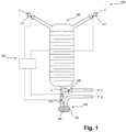
- FIG. 1 shows an advantageous embodiment of the invention in the form of a simplified block diagram
- FIG. 1 an advantageous embodiment of the invention is schematically depicted and collectively referred to with the numeral 100.
- An apparatus 100 as depicted in Figure 1 , comprises a mixing vessel 130 in fluid connection with a first metering device 110 and a second metering device 120, both of which are provided upstream the mixing vessel 130. It is to be noted, that the mixing vessel 130 is depicted in an enlarged manner so as to better discern certain details.
- the mixing vessel 130 may be provided in the form of a duct or piping, which does not differ in diameter from any other piping used elsewhere within the apparatus 100.
- a homogenizer 140 Downstream the mixing vessel 130, a homogenizer 140 is provided.
- the first and second metering devices 110, 120 are each configured to provide a desired amount of a fluid, especially a gas, to the mixing vessel 130.
- the metering devices 110, 120 are valves, which may be controlled by a control unit 150.
- the first valve 110 is configured to provide a large amount of a first gas 1 to the mixing vessel 130
- the second valve 120 is configured to provide a comparatively very small amount of a second gas 2 to the mixing vessel 130.
- Both of the valves 110, 120 are very precise in their respective working range such that the concentration of the two gases 1, 2 within the mixing vessel 130 may be precisely adjusted.
- the concentration of the second gas 2 within a mixed gas 3 produced in the mixing vessel 130 from the two gases 1, 2 may be in the ppm range and may be chosen with a precision in the ppb range such that a relative error in concentration of the second gas 2 may be smaller than 1%, for example.
- the homogenization provided by this invention ensures, that the concentration chosen with the metering devices is evenly distributed across the entirety of the mixed fluid. Without this homogenization, fluctuations in concentration across the volume of the mixed fluid may be much higher than the error margin stated above.
- the mixing vessel 130 in the depicted example is provided with guide plates therein in order to enhance the mixing of the two gases 1, 2 therein. It is to be noted, that the mixing vessel 130 does not need to be provided in the form of a tank, as depicted, but may also be provided in the form of one or more pipes or any other suitable form. Same is true for the buffer vessel 142, which might be in the form of one or more pipes or any other suitable form.
- the buffer vessel 142 may be directly at the exit outside of, or even inside, the mixing vessel 130, or further downstream of the mixing vessel, e.g. as a last component before a storage tank or before the consumer of the gas mixture.
- the mixed gas 3 is sent to the homogenizer 140 downstream the mixing vessel 130.
- the homogenizer 140 comprises a buffer vessel 142 with a filling 144 which is configured to cause disturbances within the mixed gas 3 flowing through the buffer vessel 140.
- the buffer vessel 142 is very small in comparison to the mixing vessel 130, e.g. it exhibits a volume corresponding to less than 10% of the volume of the mixing vessel 130.
- the buffer vessel 142 has a volume in the range of 0.5 L to 2 L.
- the volume of the buffer vessel 142 is chosen in relation to a fluid flow rate.
- the buffer vessel may have a volume, which corresponds to less than 10%, preferably less than 5%, 2% or 1% of the amount of mixed fluid 3 flowing through the mixing vessel 130 during operation within a time of 1 s or 1 min. It was found that even with such a small volume, the homogeneity of the so homogenized mixed gas 4 was sufficiently improved in comparison to apparatuses without the homogenizer.
- the filling 144 of the homogenizer 140 may, for example, be provided in the form of fibrous material such as steel wool, glass fibres or the like.
- suitable fillings include perforated steel plates, particularly with non-aligned perforations, foams or coarse grained particulate materials, such as steel balls, in order to cause multiple changes in flow direction within the mixed gas 3 upon passing through the filling 144.
- the filling 144 may be chosen depending on the specific gases 1, 2 to be mixed, especially in cases where at least one of the gases 1, 2 comprises corrosive or otherwise chemically reactive species.
- the homogenizer 140 may comprise a heater (not shown in the Figure) configured to heat the mixed gas 3 flowing through the buffer vessel 142. This increases a rate of diffusion within the mixed gas 3, thereby accelerating the homogenization process.
- the mixed gas 3 within the buffer vessel 142 may be heated to a temperature in the range between 50 °C to 200 °C, particularly in the range between 50 °C and 100 °C.
- this temperature range may be chosen according to the concrete fluids 1, 2, mixed within the apparatus 100.
- some chemical species may be prone to decomposition under elevated temperature conditions such that in such cases, a lower temperature may be chosen than in cases in which only thermally stable fluids 1, 2 are mixed with one another.
- control valves 146, 148 may be used to bypass the homogenizer in such cases to provide the mixed gas 3 directly to downstream processes or a storage tank without passing the homogenizer 140.
- the described solution is particularly useful for very low concentrations of one or more gas components 2, but may also be helpful in homogenizing mixed gases 3 in which the first and second components 1, 2 exhibit large differences in density, for example.
- the described approach is, of course, also suitable for mixed gases 3 comprising more than two components 1, 2. In such cases, more metering devices 110, 120 may be provided.
Landscapes
- Chemical & Material Sciences (AREA)
- Chemical Kinetics & Catalysis (AREA)
- Dispersion Chemistry (AREA)
- Engineering & Computer Science (AREA)
- Medicinal Chemistry (AREA)
- Medical Informatics (AREA)
- Health & Medical Sciences (AREA)
- Pharmacology & Pharmacy (AREA)
- General Health & Medical Sciences (AREA)
- Life Sciences & Earth Sciences (AREA)
- Wood Science & Technology (AREA)
- Endocrinology (AREA)
- Accessories For Mixers (AREA)
Abstract
The invention relates to a method of mixing at least a first fluid (1) and a second fluid (2) with one another, the method comprising providing the first fluid (1) in a desired first amount to a mixing vessel (130) having a first volume, providing the second fluid (2) in a desired second amount to the mixing vessel (130), affording a mixed fluid (3) and flowing the mixed fluid (3) through a homogenizer (140) comprising a buffer vessel (142) with a second volume and a filling (144) within the buffer vessel (142), thereby thoroughly mixing the first (1) and second (2) fluids with one another to afford a homogenized mixed fluid (4). The invention further provides an apparatus (100) for performing such a method and a homogenizer (140) for such an apparatus (100).
Description
- Mixing fluids, particularly gases, in which at least one component has a very low concentration is particularly challenging in terms of homogeneity of the mixed gas. Typically, when at least one component of the mixed fluid is in the ppm range of concentrations, fluctuations in concentration over different partial volumes and over time occur. This problem is particularly relevant in applications, which require a continuous flow or large fluid volumes, because the time required for equilibration by diffusion is very high.
- Diffusion is a process driven by local concentration differences such that the fluid components exhibit a net movement towards places with a smaller concentration. However, single molecules do not move according to a directed flow path towards the location with the lowest concentration. Single molecule movement is rather random Brownian motion, which is mainly influenced by temperature and only on occasions when two molecules come in closer proximity to one another they can attract or repel one another. This is the reason for the long equilibration duration for mixtures with low concentrations. The likelihood for two molecules of the substance with the low concentration to come into contact with one another is very small.
- The invention provides a method and an apparatus for mixing fluids as well as a homogenizer for such an apparatus with the features set out in the respective independent claims. Advantageous embodiments of those are subject-matter of the respective dependent claims as well as the following description.
- A method of mixing at least a first fluid and a second fluid with one another according to the invention comprises providing the first fluid in a desired first amount to a mixing vessel having a first volume, providing the second fluid in a desired second amount to the mixing vessel, affording a mixed fluid, and flowing the mixed fluid through a homogenizer comprising a buffer vessel with a second volume and a filling within the buffer vessel, thereby thoroughly mixing the first and second fluids with one another to afford a homogenized mixed fluid. Particularly, the filling of the buffer vessel is configured to cause disturbances within the mixed gas flowing through the buffer vessel. Therefore, the mixed fluid is forced to change its flow direction within the homogenizer. The motion of the single molecules is, therefore, not solely governed by Brownian motion, which greatly aids the homogenization of the mixed fluid.
- It is to be understood, that the mixing vessel can be any (particularly but not necessarily closed) hollow structure, in which fluids may be stored, injected, conducted or otherwise kept, like a container or receptacle or a duct or pipe or conduit, and can especially be realized in the form of a duct, into which the at least two fluids are dosed. In some embodiments, a dedicated vessel may be foreseen as the mixing vessel. The mixing vessel, in whatever form provided, may comprise baffle plates in order to provide for disturbances in the flow of the mixed fluid to aid homogenization.
- Be it further noted, that, although the invention is described in the context of mixing two fluids with one another, it may just as well be used for mixing more than two different fluids with one another.
- Particularly, the first fluid and the second fluid are gases.
- Particularly, the second amount is in the range of less than 1%, 0.3%, 0.1%, 300 ppm, 100 ppm, 30 ppm, 10 ppm, 3 ppm, 1 ppm, 300 ppb or less than 100 ppb, in relation to the total amount of the mixed fluid by volume or mass, respectively. This is a concentration regime, which poses particularly difficult challenges in terms of homogenization.
- The method may advantageously further comprise heating the mixed gas flowed through the buffer vessel in order to increase a rate of diffusion within the mixed gas, thereby accelerating the homogenization process.
- An apparatus for mixing at least a first fluid and a second fluid with one another according to the invention comprises a mixing vessel, configured to receive at least the first and the second fluid and to produce a mixed fluid therefrom, a first fluid metering device, configured to provide a desired first amount of the first fluid to the mixing vessel, a second fluid metering device, configured to provide a desired second amount of the second fluid to the mixing vessel, and a homogenizer downstream of the mixing vessel, the homogenizer comprising a buffer vessel with a filling, wherein the filling is configured to cause disturbances within a fluid flowing through the buffer vessel. In other words, the apparatus is configured for performing a method as just described.
- Specifically, the second fluid metering device (or at least one of the fluid metering devices) is configured to provide the second amount such that the second amount is less than 1%, 0.3%, 0.1%, 300 ppm, 100 ppm, 30 ppm, 10 ppm, 3 ppm, 1 ppm, 300 ppb or less than 100 ppb, in relation to the total amount of the mixed fluid by volume or mass, respectively. This is a concentration regime, which poses particularly difficult challenges in terms of homogenization.
- In advantageous embodiments, the filling of the buffer vessel comprises one or more selected from the group consisting of fibres, particularly comprising metal and/or glass and/or carbon and/or polymeric fibres, perforated sheet material, coarse-grained particulate material, foams, macroporous material and structured substrate. Those are particularly well suited fillers for causing disturbances without causing an inacceptably high pressure drop.
- The filling may take up a volume in the range of 0.5% to 99.5% of the buffer vessel's inner volume, particularly in the range of 5% to 95%, more particularly in the range of 10% to 75%, preferably in the range of 25% to 50%. The specific range may be chosen depending on the filler material used and/or according to the desired homogeneity and/or the maximum acceptable pressure drop.
- Particulary, the buffer vessel has a volume of less than 100 L (litres), particularly in the range of 0.1 L to 10 L, preferably in the range of 0.5 L to 2 L. The buffer vessel preferably has a volume of less than 20%, particularly less than 10%, preferably less than 5%, of the volume of the mixing vessel. In some embodiments, the buffer vessel has a volume, which corresponds to less than 10%, preferably less than 5%, 2% or 1% of the amount of mixed fluid flowing through the mixing vessel during operation within a time of 1 s or 1 min. Such a small buffer volume was found to be sufficient for a favourable homogenization effect and does not cause a drastically spatial footprint or investment costs of the apparatus as a whole.
- In advantageous embodiments, the homogenizer comprises a heater configured to heat a gas flowed through the buffer vessel. As already explained above, this aids accelerate the homogenization process within the buffer vessel.
- A homogenizer for an apparatus according to the invention comprises a buffer vessel with a filling configured to cause disturbances in a fluid flowed therethrough.
-
Figure 1 shows an advantageous embodiment of the invention in the form of a simplified block diagram - In the following, the invention is explained in further detail with reference to the appended drawing. In the drawing, reference numerals used for referring to a component of an embodiment of an apparatus according to the invention may also be used to refer to a method step carried out within the respective apparatus component or vice versa.
- In
Figure 1 , an advantageous embodiment of the invention is schematically depicted and collectively referred to with thenumeral 100. - An
apparatus 100, as depicted inFigure 1 , comprises amixing vessel 130 in fluid connection with afirst metering device 110 and asecond metering device 120, both of which are provided upstream themixing vessel 130. It is to be noted, that themixing vessel 130 is depicted in an enlarged manner so as to better discern certain details. Themixing vessel 130 may be provided in the form of a duct or piping, which does not differ in diameter from any other piping used elsewhere within theapparatus 100. - Downstream the
mixing vessel 130, ahomogenizer 140 is provided. - The first and
second metering devices mixing vessel 130. In the example shown, themetering devices control unit 150. - The
first valve 110 is configured to provide a large amount of a first gas 1 to themixing vessel 130, while thesecond valve 120 is configured to provide a comparatively very small amount of asecond gas 2 to themixing vessel 130. Both of thevalves gases 1, 2 within themixing vessel 130 may be precisely adjusted. For example, the concentration of thesecond gas 2 within a mixedgas 3 produced in themixing vessel 130 from the twogases 1, 2 may be in the ppm range and may be chosen with a precision in the ppb range such that a relative error in concentration of thesecond gas 2 may be smaller than 1%, for example. The homogenization provided by this invention ensures, that the concentration chosen with the metering devices is evenly distributed across the entirety of the mixed fluid. Without this homogenization, fluctuations in concentration across the volume of the mixed fluid may be much higher than the error margin stated above. - The
mixing vessel 130 in the depicted example is provided with guide plates therein in order to enhance the mixing of the twogases 1, 2 therein. It is to be noted, that themixing vessel 130 does not need to be provided in the form of a tank, as depicted, but may also be provided in the form of one or more pipes or any other suitable form. Same is true for thebuffer vessel 142, which might be in the form of one or more pipes or any other suitable form. Thebuffer vessel 142 may be directly at the exit outside of, or even inside, themixing vessel 130, or further downstream of the mixing vessel, e.g. as a last component before a storage tank or before the consumer of the gas mixture. - The mixed
gas 3 is sent to thehomogenizer 140 downstream themixing vessel 130. Thehomogenizer 140 comprises abuffer vessel 142 with afilling 144 which is configured to cause disturbances within the mixedgas 3 flowing through thebuffer vessel 140. Thebuffer vessel 142 is very small in comparison to themixing vessel 130, e.g. it exhibits a volume corresponding to less than 10% of the volume of themixing vessel 130. In a particularly advantageous embodiment, thebuffer vessel 142 has a volume in the range of 0.5 L to 2 L. Preferably, the volume of thebuffer vessel 142 is chosen in relation to a fluid flow rate. For example, the buffer vessel may have a volume, which corresponds to less than 10%, preferably less than 5%, 2% or 1% of the amount of mixedfluid 3 flowing through themixing vessel 130 during operation within a time of 1 s or 1 min. It was found that even with such a small volume, the homogeneity of the so homogenized mixedgas 4 was sufficiently improved in comparison to apparatuses without the homogenizer. - The filling 144 of the
homogenizer 140 may, for example, be provided in the form of fibrous material such as steel wool, glass fibres or the like. Other suitable fillings include perforated steel plates, particularly with non-aligned perforations, foams or coarse grained particulate materials, such as steel balls, in order to cause multiple changes in flow direction within themixed gas 3 upon passing through the filling 144. The filling 144 may be chosen depending on thespecific gases 1, 2 to be mixed, especially in cases where at least one of thegases 1, 2 comprises corrosive or otherwise chemically reactive species. - In some embodiments, the
homogenizer 140 may comprise a heater (not shown in the Figure) configured to heat themixed gas 3 flowing through thebuffer vessel 142. This increases a rate of diffusion within themixed gas 3, thereby accelerating the homogenization process. For example, themixed gas 3 within thebuffer vessel 142 may be heated to a temperature in the range between 50 °C to 200 °C, particularly in the range between 50 °C and 100 °C. Obviously, this temperature range may be chosen according to theconcrete fluids 1, 2, mixed within theapparatus 100. For example, some chemical species may be prone to decomposition under elevated temperature conditions such that in such cases, a lower temperature may be chosen than in cases in which only thermallystable fluids 1, 2 are mixed with one another. - However, in some cases, for example when the concentration of the
second gas 2 within themixed gas 3 is set to be higher, e.g. more than 1% by volume, thehomogenizer 140 may not be necessary in order to achieve sufficient homogeneity. Therefore,control valves mixed gas 3 directly to downstream processes or a storage tank without passing thehomogenizer 140. - The described solution is particularly useful for very low concentrations of one or
more gas components 2, but may also be helpful in homogenizingmixed gases 3 in which the first andsecond components 1, 2 exhibit large differences in density, for example. The described approach is, of course, also suitable formixed gases 3 comprising more than twocomponents 1, 2. In such cases,more metering devices
Claims (14)
- Method of mixing at least a first fluid (1) and a second fluid (2) with one another, the method comprisingproviding the first fluid (1) in a desired first amount to a mixing vessel (130) having a first volume,providing the second fluid (2) in a desired second amount to the mixing vessel, affording a mixed fluid (3), andflowing the mixed fluid (3) through a homogenizer (140) comprising a buffer vessel (142) with a second volume and a filling (144) within the buffer vessel (142), thereby thoroughly mixing the first (1) and second (2) fluids with one another to afford a homogenized mixed fluid (4).
- Method according to claim 1, wherein the first fluid (1) and the second fluid (2) are gases.
- Method according to claim 1 or 2, wherein the second amount is in the range of less than 1 %, 0.3 %, 0.1 %, 300 ppm, 100 ppm, 30 ppm, 10 ppm, 3 ppm, 1 ppm, 300 ppb or less than 100 ppb, in relation to the total amount of the mixed fluid by volume or mass, respectively.
- Method according to any of the preceding claims, wherein the filling (144) of the buffer vessel (142) is configured to cause disturbances within the mixed gas (3) flowed through the buffer vessel (142).
- Method according to any of the preceding claims, wherein the mixed gas (3) is heated within the buffer vessel (142).
- Apparatus (100) for mixing at least a first fluid (1) and a second fluid (2) with one another, comprisinga mixing vessel (130), configured to receive at least the first (1) and the second (2) fluid and to produce a mixed fluid (3) therefrom,a first fluid metering device (110), configured to provide a desired first amount of the first fluid (1) to the mixing vessel (130),a second fluid metering device (120), configured to provide a desired second amount of the second fluid (2) to the mixing vessel (130), anda homogenizer (140) downstream of the mixing vessel (130), the homogenizer (140) comprising a buffer vessel (142) with a filling (144), wherein the filling (144) is configured to cause disturbances within a fluid (3) flowing through the buffer vessel (142).
- Apparatus (100) according to claim 6, wherein the first (1) and the second (2) fluids are gases.
- Apparatus (100) according to claim 6 or 7, wherein the second fluid metering device (120) is configured to provide the second amount such that the second amount is less than 1%, 0.3%, 0.1%, 300 ppm, 100 ppm, 30 ppm, 10 ppm, 3 ppm, 1 ppm, 300 ppb or less than 100 ppb, in relation to the total amount of the mixed fluid (3) by volume or mass, respectively.
- Apparatus (100) according to any of claims 6 through 8, wherein the filling (144) of the buffer vessel (142) comprises one or more selected from the group consisting of fibres, particularly comprising metal and/or glass and/or carbon and/or polymeric fibres, perforated sheet material, coarse-grained particulate material, foams, macroporous material and structured substrate.
- Apparatus (100) according to any of claims 6 through 9, wherein the filling (144) takes up a volume in the range of 0.5% to 99.5% of the buffer vessel's (142) inner volume, particularly in the range of 5% to 95%, more particularly in the range of 10% to 75%, preferably in the range of 25% to 50%.
- Apparatus (100) according to any one of claims 6 through 10, wherein the buffer vessel (142) has a volume of less than 100 L, particularly in the range of 0.1 L to 10 L, preferably in the range of 0.5 L to 2 L.
- Apparatus (100) according to any of claims 6 through 11, wherein the buffer vessel (142) has a volume of less than 20%, particularly less than 10%, preferably less than 5%, of the volume of the mixing vessel (130) and/or wherein the buffer vessel (142) has an inner volume corresponding to less than 10% or less than 5%, 2% or 1 % of a maximum volume of mixed gas (3) passing through the mixing vessel (130) during operation of the apparatus (100) within 1 s or 1 min.
- Apparatus (100) according to any of claims 6 through 12, wherein the homogenizer (140) comprises a heater configured to heat a gas (3) flowed through the buffer vessel (142).
- Homogenizer (140) for an apparatus (100) according to any of claims 5 through 11, the homogenizer (140) comprising a buffer vessel (142) with a filling (144) configured to cause disturbances in a fluid (3) flowed therethrough.
Priority Applications (1)
| Application Number | Priority Date | Filing Date | Title |
|---|---|---|---|
| EP22020111.5A EP4245404A1 (en) | 2022-03-15 | 2022-03-15 | Method and apparatus for mixing fluids in low concentrations |
Applications Claiming Priority (1)
| Application Number | Priority Date | Filing Date | Title |
|---|---|---|---|
| EP22020111.5A EP4245404A1 (en) | 2022-03-15 | 2022-03-15 | Method and apparatus for mixing fluids in low concentrations |
Publications (1)
| Publication Number | Publication Date |
|---|---|
| EP4245404A1 true EP4245404A1 (en) | 2023-09-20 |
Family
ID=80785216
Family Applications (1)
| Application Number | Title | Priority Date | Filing Date |
|---|---|---|---|
| EP22020111.5A Withdrawn EP4245404A1 (en) | 2022-03-15 | 2022-03-15 | Method and apparatus for mixing fluids in low concentrations |
Country Status (1)
| Country | Link |
|---|---|
| EP (1) | EP4245404A1 (en) |
Citations (3)
| Publication number | Priority date | Publication date | Assignee | Title |
|---|---|---|---|---|
| GB1311467A (en) * | 1968-12-24 | 1973-03-28 | British Federal Welder | Gas mixing |
| US5284275A (en) * | 1990-01-22 | 1994-02-08 | John Shomer | Dispensing container for multi-component curable compositions using a heating element to cause mixing |
| EP2172418A1 (en) * | 2007-07-30 | 2010-04-07 | JGC Corporation | Gas mixing device, and synthetic gas producing apparatus |
-
2022
- 2022-03-15 EP EP22020111.5A patent/EP4245404A1/en not_active Withdrawn
Patent Citations (3)
| Publication number | Priority date | Publication date | Assignee | Title |
|---|---|---|---|---|
| GB1311467A (en) * | 1968-12-24 | 1973-03-28 | British Federal Welder | Gas mixing |
| US5284275A (en) * | 1990-01-22 | 1994-02-08 | John Shomer | Dispensing container for multi-component curable compositions using a heating element to cause mixing |
| EP2172418A1 (en) * | 2007-07-30 | 2010-04-07 | JGC Corporation | Gas mixing device, and synthetic gas producing apparatus |
Similar Documents
| Publication | Publication Date | Title |
|---|---|---|
| US20150316524A1 (en) | System and Apparatus for a Laboratory Scale Reactor | |
| CN102258958A (en) | Dynamic gas distributing system for standard gas | |
| CN104772055B (en) | A kind of micro bubble generator and application thereof | |
| US10195543B2 (en) | Methods and systems for treating a switchable polarity material, and related methods of liquid treatment | |
| HK1201227A1 (en) | Process and apparatus for gas-enriching a liquid | |
| US8608138B2 (en) | Inline infusion device and method for introduction of a gas into a flowing media | |
| EP2570179A1 (en) | Method and apparatus for dynamic gas mixture production | |
| JP3951385B2 (en) | Apparatus and method for adjusting dissolved gas concentration in liquid | |
| CN108348882A (en) | systems that bring gases and liquids into contact | |
| US20090010097A1 (en) | System and Method for Heat Treating a Homogenized Fluid Product | |
| DE10304855A1 (en) | Device and method for the simultaneous agitation of reaction mixtures | |
| US5806976A (en) | high-speed fluid mixing device | |
| GB2535659A (en) | Methods and devices for performing reactions | |
| KR101254326B1 (en) | Mixing device for supercritical fluid and liquid chemical | |
| CN101688304A (en) | Method for controlling process gas concentration | |
| EP3254746A1 (en) | Radial adsorption apparatus comprising a cooling device | |
| US20130208561A1 (en) | Inline infusion device and method for introduction of a gas into a flowing media | |
| Rahmati et al. | Deoxygenation of Water for Small-Scale Laboratory Studies in Hydraulic Engineering | |
| Zwijnenberg et al. | Divalent Cation Competition in Donnan Dialysis for the Recovery of Ammonium | |
| Romanik et al. | Preliminary studies on the optimisation of the operating conditions of the BTF for the hydrogen sulfide removal | |
| CN112880758B (en) | A system and method for continuous and automatic preparation of trace gases | |
| Gómez‐Díaz et al. | Gas/liquid mass transfer processes in a carbon dioxide/alkane system | |
| RU2794323C1 (en) | Oil treatment method | |
| CN217341292U (en) | Device for generating uniform hydrogel microspheres on large scale | |
| JP7578729B2 (en) | Method for providing uniform feed flow inside a plug flow reactor. |
Legal Events
| Date | Code | Title | Description |
|---|---|---|---|
| PUAI | Public reference made under article 153(3) epc to a published international application that has entered the european phase |
Free format text: ORIGINAL CODE: 0009012 |
|
| STAA | Information on the status of an ep patent application or granted ep patent |
Free format text: STATUS: THE APPLICATION HAS BEEN PUBLISHED |
|
| AK | Designated contracting states |
Kind code of ref document: A1 Designated state(s): AL AT BE BG CH CY CZ DE DK EE ES FI FR GB GR HR HU IE IS IT LI LT LU LV MC MK MT NL NO PL PT RO RS SE SI SK SM TR |
|
| STAA | Information on the status of an ep patent application or granted ep patent |
Free format text: STATUS: THE APPLICATION IS DEEMED TO BE WITHDRAWN |
|
| 18D | Application deemed to be withdrawn |
Effective date: 20240321 |