EP4245397A1 - Gas-liquid separator - Google Patents
Gas-liquid separator Download PDFInfo
- Publication number
- EP4245397A1 EP4245397A1 EP21891516.3A EP21891516A EP4245397A1 EP 4245397 A1 EP4245397 A1 EP 4245397A1 EP 21891516 A EP21891516 A EP 21891516A EP 4245397 A1 EP4245397 A1 EP 4245397A1
- Authority
- EP
- European Patent Office
- Prior art keywords
- water
- storage portion
- water storage
- gas
- tubular wall
- Prior art date
- Legal status (The legal status is an assumption and is not a legal conclusion. Google has not performed a legal analysis and makes no representation as to the accuracy of the status listed.)
- Pending
Links
Images


Classifications
-
- B—PERFORMING OPERATIONS; TRANSPORTING
- B01—PHYSICAL OR CHEMICAL PROCESSES OR APPARATUS IN GENERAL
- B01D—SEPARATION
- B01D45/00—Separating dispersed particles from gases or vapours by gravity, inertia, or centrifugal forces
- B01D45/04—Separating dispersed particles from gases or vapours by gravity, inertia, or centrifugal forces by utilising inertia
- B01D45/08—Separating dispersed particles from gases or vapours by gravity, inertia, or centrifugal forces by utilising inertia by impingement against baffle separators
-
- B—PERFORMING OPERATIONS; TRANSPORTING
- B01—PHYSICAL OR CHEMICAL PROCESSES OR APPARATUS IN GENERAL
- B01D—SEPARATION
- B01D29/00—Filters with filtering elements stationary during filtration, e.g. pressure or suction filters, not covered by groups B01D24/00 - B01D27/00; Filtering elements therefor
- B01D29/01—Filters with filtering elements stationary during filtration, e.g. pressure or suction filters, not covered by groups B01D24/00 - B01D27/00; Filtering elements therefor with flat filtering elements
- B01D29/05—Filters with filtering elements stationary during filtration, e.g. pressure or suction filters, not covered by groups B01D24/00 - B01D27/00; Filtering elements therefor with flat filtering elements supported
-
- B—PERFORMING OPERATIONS; TRANSPORTING
- B01—PHYSICAL OR CHEMICAL PROCESSES OR APPARATUS IN GENERAL
- B01D—SEPARATION
- B01D29/00—Filters with filtering elements stationary during filtration, e.g. pressure or suction filters, not covered by groups B01D24/00 - B01D27/00; Filtering elements therefor
- B01D29/50—Filters with filtering elements stationary during filtration, e.g. pressure or suction filters, not covered by groups B01D24/00 - B01D27/00; Filtering elements therefor with multiple filtering elements, characterised by their mutual disposition
- B01D29/52—Filters with filtering elements stationary during filtration, e.g. pressure or suction filters, not covered by groups B01D24/00 - B01D27/00; Filtering elements therefor with multiple filtering elements, characterised by their mutual disposition in parallel connection
-
- B—PERFORMING OPERATIONS; TRANSPORTING
- B01—PHYSICAL OR CHEMICAL PROCESSES OR APPARATUS IN GENERAL
- B01D—SEPARATION
- B01D45/00—Separating dispersed particles from gases or vapours by gravity, inertia, or centrifugal forces
- B01D45/18—Cleaning-out devices
-
- H—ELECTRICITY
- H01—ELECTRIC ELEMENTS
- H01M—PROCESSES OR MEANS, e.g. BATTERIES, FOR THE DIRECT CONVERSION OF CHEMICAL ENERGY INTO ELECTRICAL ENERGY
- H01M8/00—Fuel cells; Manufacture thereof
- H01M8/04—Auxiliary arrangements, e.g. for control of pressure or for circulation of fluids
- H01M8/04082—Arrangements for control of reactant parameters, e.g. pressure or concentration
- H01M8/04089—Arrangements for control of reactant parameters, e.g. pressure or concentration of gaseous reactants
- H01M8/04119—Arrangements for control of reactant parameters, e.g. pressure or concentration of gaseous reactants with simultaneous supply or evacuation of electrolyte; Humidifying or dehumidifying
- H01M8/04156—Arrangements for control of reactant parameters, e.g. pressure or concentration of gaseous reactants with simultaneous supply or evacuation of electrolyte; Humidifying or dehumidifying with product water removal
- H01M8/04164—Arrangements for control of reactant parameters, e.g. pressure or concentration of gaseous reactants with simultaneous supply or evacuation of electrolyte; Humidifying or dehumidifying with product water removal by condensers, gas-liquid separators or filters
-
- Y—GENERAL TAGGING OF NEW TECHNOLOGICAL DEVELOPMENTS; GENERAL TAGGING OF CROSS-SECTIONAL TECHNOLOGIES SPANNING OVER SEVERAL SECTIONS OF THE IPC; TECHNICAL SUBJECTS COVERED BY FORMER USPC CROSS-REFERENCE ART COLLECTIONS [XRACs] AND DIGESTS
- Y02—TECHNOLOGIES OR APPLICATIONS FOR MITIGATION OR ADAPTATION AGAINST CLIMATE CHANGE
- Y02E—REDUCTION OF GREENHOUSE GAS [GHG] EMISSIONS, RELATED TO ENERGY GENERATION, TRANSMISSION OR DISTRIBUTION
- Y02E60/00—Enabling technologies; Technologies with a potential or indirect contribution to GHG emissions mitigation
- Y02E60/30—Hydrogen technology
- Y02E60/50—Fuel cells
Definitions
- the present invention relates to gas-liquid separators.
- Patent Document 1 Gas-liquid separators that separate water from gas are described in Patent Document 1 and Patent Document 2.
- the gas-liquid separator described in Patent Document 1 is structured to separate water from anode gas in an upper part of a housing to recover the water in a water storage portion in a lower part of the housing, and drain the water stored in the water storage portion by opening a drain channel communicating with the water storage portion by an electromagnetic on-off valve.
- the gas-liquid separator described in Patent Document 2 includes a valve device in its lower part, and is structured to drain water in the lower part of the gas-liquid separator by opening the valve device.
- a heating device is disposed in a fluid inlet portion that introduces a fluid into a valve body.
- the valve device is structured so that, when the valve device is frozen, the valve device can be thawed by heat from the heating device.
- One solution to this disadvantage is to provide a heating device in the gas-liquid separator as in Patent Document 2 so that water can be drained by thawing the valve device by the heat from the heating device.
- the gas-liquid separator with the heating device increases manufacturing cost, and reduces the cruising range of the vehicle as such a gas-liquid separator consumes generated energy.
- the water cannot be drained until the valve device is thawed.
- a characteristic structure of a gas-liquid separator is that the gas-liquid separator includes: a housing to which water-containing gas is supplied; a gas-liquid separation portion that is located in an upper part of the housing and that separates water from the water-containing gas; a first water storage portion that is located in a lower part of the housing and that receives and stores the water separated by the gas-liquid separation portion, the first water storage portion having an annular shape as viewed in plan; a second water storage portion that is located below the first water storage portion in a bottom part of the housing, and to which the water from the first water storage portion is supplied; a valve mechanism that allows the water stored in the second water storage portion to be drained and to stop being drained by opening and closing a drain channel communicating with a bottom part of the second water storage portion; a tubular wall that is located inside the first water storage portion and that stores the water in the first water storage portion until the water overflows, and guides the overflowed water into the second water storage portion; and a lid-like
- the water separated from the water-containing gas in the gas-liquid separation portion is first received by and stored in the first water storage portion.
- the water overflows an upper end of the tubular wall and is supplied to the second water storage portion.
- the water stored in the second water storage portion can be drained to the outside by opening the valve mechanism.
- the lid-like member covers the upper side of the tubular wall, a lower part of the first water storage portion and an upper part of the second water storage portion are connected by a flow channel in which entry and exit of external gas are restricted.
- the pressure in the second water storage portion drops, so that the pressure in the first water storage portion rises relative to the pressure in the second water storage portion.
- This pressure difference causes the water in the first water storage portion to overflow the upper end of the tubular wall and flow into the second water storage portion, so that the water level in the first water storage portion can be lowered.
- the water having flowed into the second water storage portion can be drained to the outside through the valve mechanism.
- a vehicle is equipped with a fuel cell and the gas-liquid separator. Since the vehicle is equipped with the gas-liquid separator having the above characteristic structure, the water surface in the first water storage portion can be significantly lowered by merely opening the valve mechanism and draining the water in the second water storage portion when the vehicle is parked in a cold region. Accordingly, even if a small amount of water that is present inside the fuel cell flows into the housing after the water in the second water storage portion is drained, or even if water droplets on the inner surface of the housing fall, this water will be received by the first water storage portion, and will not flow into the second water storage portion. A disadvantage that an area from the drain channel to the valve mechanism is frozen can thus be eliminated.
- the gas-liquid separator is thus structured that can satisfactorily drain water in the second water storage portion and that prevents water from being stored in the second storage portion after the fuel cell stops generating electricity.
- the lid-like member may include a vertical wall portion separated from the tubular wall.
- the water when the level of the water stored in the first water storage portion is higher than a lower end of the vertical wall portion, the water is present in clearance between the tubular wall and the vertical wall portion.
- the lower part of the first water storage portion and the upper part of the second water storage portion can thus be connected by a flow channel in which entry and exit of external gas are restricted.
- a plurality of rib bodies that causes water to flow from the first water storage portion to the second water storage portion between the tubular wall and the vertical wall portion may be located on either or both of an outer wall surface of the tubular wall and an inner wall surface of the vertical wall portion.
- water By forming the plurality of rib bodies, water can be caused to flow into the clearance between the outer wall surface of the tubular wall and the inner wall surface of the vertical wall portion of the lid-like member. This makes it easier for the water in the first water storage portion to flow into the second water storage portion.
- the vertical wall portion of the lid-like member may be fitted outside the tubular wall, and the vertical wall portion may have a slit extending from a lower end of the vertical wall portion to a position above the upper end of the tubular wall as viewed from side with the vertical wall portion fitted outside the tubular wall.
- a drain guide rib that guides the water having overflowed the upper end of the tubular wall into the second water storage portion may be located on an inner periphery of the tubular wall.
- the water flowing from the upper end of the tubular wall along an inner wall surface of the tubular wall can be guided by the drain guide rib to smoothly flow into the second water storage portion.
- the lid-like member may include, between the gas-liquid separation portion and the first water storage portion, a filter that removes dust contained in the water separated by the gas-liquid separation portion.
- the filter can remove the dust, so that a disadvantage such as a proper operation of the valve mechanism being hindered by the dust contained in the water can be avoided.
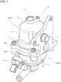
- FIGS. 1 to 5 show a gas-liquid separator A that separates water contained in anode off-gas (example of the water-containing gas) discharged from the anode of a fuel cell mounted on a fuel cell vehicle (FCV).
- This gas-liquid separator A includes an inlet portion 1 and an outlet portion 2 at upper positions of a housing H, and includes an electromagnetic on-off valve 3 (example of the valve mechanism) at a bottom position of the housing H.
- a gas-liquid separation portion 4 is located in the upper part of the internal space of the housing H, and a first water storage portion 5 and a second water storage portion 6 are located in the lower part of the internal space of the housing H.
- the fuel cell generates electricity as fuel gas containing hydrogen gas is supplied to the anode through anode gas flow channels and oxidant gas (air containing oxygen) is supplied to the cathode through cathode gas flow channels.
- oxidant gas air containing oxygen
- the anode off-gas discharged from the anode contains unreacted hydrogen gas and water.
- the gas-liquid separator A is used to separate and drain the water contained in the anode off-gas to recover the hydrogen gas contained in the anode gas, and return the recovered hydrogen gas to the anode gas flow channels of the fuel cell.
- the housing H has an upper housing 10 and a lower housing 20, and the upper housing 10 and the lower housing 20 are put together by placing an upper flange 10f of the upper housing 10 on top of a lower flange 20f of the lower housing 20 and fastening them together with a plurality of fastening bolts 7.
- the tubular inlet portion 1 is formed in such an attitude that the inlet portion 1 protrudes laterally from a tubular upper side wall 11 of the upper housing 10, and the outlet portion 2 is formed in such an attitude that the outlet portion 2 protrudes upward from a flat upper end wall 12 at the upper end of the upper housing 10.
- the upper housing 10 and the lower housing 20 are herein made of resin, but may be made of metal such as aluminum.
- the gas-liquid separation portion 4 containing a plurality of plate-like collision walls 13 for separating water contained in the anode off-gas as the anode off-gas supplied from the inlet portion 1 comes into contact with the collision walls 13 is formed in the internal space of the upper housing 10.
- This gas-liquid separation portion 4 functions to separate water contained in the gas and cause the water to drop downward by successively bringing the anode off-gas introduced from the inlet portion 1 into contact with the plurality of collision walls 13. The resultant dry gas after the separation of the water is discharged upward from the outlet portion 2.
- the lower housing 20 is a housing in which the following walls are formed integrally: a lower side wall 21 having a cylindrical shape about the vertical axis Y; a guide wall 22 that is continuous with the lower side of the lower side wall 21 and has such a shape that gradually tapers toward its lower side and that guides water; a tilted wall 23 that is continuous with the lower side of the guide wall 22 and has such a funnel shape that gradually tapers toward its lower side; a tubular wall 24 that is continuous with the lower side of the tilted wall 23 and has a cylindrical shape about the vertical axis Y; and a bottom wall 25 that closes the lower end of the tubular wall 24.
- a vertical intermediate wall 23a is formed about the vertical axis Y in a boundary portion that is continuous with the guide wall 22.
- the tubular wall 24 is formed in a region extending upward and downward from a boundary portion with the tilted wall 23.
- An annular space between the outer side of an upper region 24a of the tubular wall 24 that extends upward from the boundary portion with the tilted wall 23 and the inner sides of the tilted wall 23 and the intermediate wall 23a forms the first water storage portion 5.
- a cylindrical space surrounded by the tubular wall 24 and the bottom wall 25 forms the second water storage portion 6.
- a drain channel 26 that communicates with a space in the bottom part of the second water storage portion 6 is formed in the lower housing 20.
- the electromagnetic on-off valve 3 is provided outside the lower end portion of the lower housing 20 so that water drainage can be controlled by opening and closing the outer end of the drain channel 26.
- the drain channel 26 is formed with a small diameter like an orifice in order to reduce discharge of the anode off-gas containing unreacted hydrogen and drain a constant amount of water when the electromagnetic on-off valve 3 is opened and water in the second water storage portion 6 is drained.
- this gas-liquid separator A the positional relationship between the first water storage portion 5 and the second water storage portion 6 is set so that water separated from the anode off-gas by the gas-liquid separation portion 4 is received and stored in the first water storage portion 5 of the lower housing 20 and, as shown in FIG. 6 , the water stored in the first water storage portion 5 is then caused to overflow the upper end of the tubular wall 24 located inside the first water storage portion 5 and thus this water can be stored in the second water storage portion 6.
- this structure includes a lid-like member 30 that controls the amount of water that flows from the first water storage portion 5 into the second water storage portion 6.
- the lid-like member 30 is a member in which the following portions are formed integrally: a tubular vertical wall portion 31 that is disposed (fitted) at a position separated outward from the outer wall surface of the upper region 24a of the tubular wall 24 and located at such a position that the vertical wall portion 31 overlaps the upper region 24a as viewed from the side (as viewed in a direction perpendicular to the vertical axis Y) in this state; and a lid-like portion 32 that closes the upper end of the vertical wall portion 31. That is, the lid-like member 30 covers the upper side of the tubular wall 24.
- the gas-liquid separator A has such a structure that the vertical wall portion 31 of the lid-like member 30 covers the outside of the tubular wall 24 and the lid-like portion 32 closes the upper end of the vertical wall portion 31 of the lid-like member 30. Therefore, when the level of the water stored in the first water storage portion 5 is higher than the lower end of the vertical wall portion 31, the lower part of the first water storage portion 5 and the upper part of the second water storage portion 6 are connected by a flow channel in which entry and exit of external gas are restricted. As will be described later, a plurality of slits 31a is formed in the vertical wall portion 31. These slits 31a allow gas to flow to some extent.
- the lid-like member 30 includes: a plurality of frames 33 extending radially outward from the outer surface of the upper end of the vertical wall portion 31 and the outer edge of the lid-like portion 32; a ring-shaped portion 34 connected to the extended ends of the plurality of frames 33; and a filter 35 disposed between the ring-shaped portion 34 and the lid-like portion 32.
- the outer shape of the ring-shaped portion 34 is determined so that the ring-shaped portion 34 is fitted in the intermediate wall 23a at the position of the upper end of the tilted wall 23.
- the filter 35 functions to remove dust contained in water separated by the gas-liquid separation portion 4 and supplied from the gas-liquid separation portion 4. That is, the filter 35 is located between the gas-liquid separation portion 4 and the first water storage portion 5.
- An O-ring 36 is mounted around the ring-shaped portion 34 to seal the gap between the ring-shaped portion 34 and the inner periphery of the intermediate wall 23a.
- the lower end of the ring-shaped portion 34 is supported by the upper end of the tilted wall 23, and the lower surface of the lid-like portion 32 contacts the upper ends of drain guide ribs 28 that will be described later.
- the lid-like member 30 is thus supported at a proper position in the vertical direction.
- the lower end of the vertical wall portion 31 is tilted with respect to the wall surface so as to be parallel to the tile of the tilted wall 23. Since the lid-like member 30 is thus supported at the proper position, clearance G is provided in the vertical direction between the lower end of the vertical wall portion 31 and the tilted wall 23.
- Clearance T is also provided in the radial direction between the outer wall surface of the upper region 24a of the tubular wall 24 and the inner wall surface of the vertical wall portion 31.
- rib bodies 27 in a vertical attitude are formed on the outer periphery of the upper region 24a so that the clearance T between the outer wall surface of the upper region 24a of the tubular wall 24 and the inner wall surface of the vertical wall portion 31 becomes uniform along the entire circumference as viewed in plan.
- a plurality of drain guide ribs 28 is formed in a region from the inner periphery to outer periphery of the tubular wall 24 in order to assist the flow of water having overflowed the upper end of the tubular wall 24.
- the drain guide ribs 28 are formed so as to protrude upward from the upper end of the tubular wall 24 (upper end of the upper region 24a).
- the plurality of rib bodies 27 thus restricts displacement (displacement in the radial direction) of the vertical wall portion 31 of the lid-like member 30 toward the tubular wall 24 when the lid-like member 30 is mounted inside the lower housing 20.
- the clearance T is thus kept uniform along the entire circumference, so that unevenness of the water flow in the clearance T can be eliminated and a satisfactory water flow can be maintained.
- drain guide ribs 28 are formed, water flowing on the inner surface of the tubular wall 24 is smoothly guided. As described above, the upper ends of the drain guide ribs 28 contact the lower surface of the lid-like portion 32 of the lid-like member 30. The position of the lid-like member 30 in the vertical direction is thus determined.
- the vertical wall portion 31 has the slits 31a extending from the lower end of the vertical wall portion 31 to a position above the upper end of the tubular wall 24 (upper end of the upper region 24a) as viewed from the side.
- the cut ends of the upward extending slits 31a are located below the filter 35 (on the first water storage portion 5 side).
- the water continuously separated from the anode off-gas by the gas-liquid separation portion 4 is supplied to the first water storage portion 5.
- the water surface in the first water storage portion 5 reaches above the upper end of the tubular wall 24, the water in the first water storage portion 5 overflows the upper end of the tubular wall 24 and is supplied to the second water storage portion 6, as shown in FIG. 6 .
- the electromagnetic on-off valve 3 Since the amount of water separated from the anode off-gas by the gas-liquid separation portion 4 can be estimated from the amount of electricity generated by the fuel cell, the electromagnetic on-off valve 3 is controlled to open every time the estimated amount of water reaches a preset value. In this gas-liquid separator A, the pressure in the internal space of the housing H is higher than the pressure of outside air. Therefore, when the electromagnetic on-off valve 3 is opened, the water in the second water storage portion 6 is drained through the drain channel 26 due to the pressure difference between the second water storage portion 6 and the outside air.
- the pressure in the second water storage portion 6 becomes lower than the pressure in the first water storage portion 5. Accordingly, as shown in FIG. 7 , water in the clearance T out of the water stored in the first water storage portion 5 overflows the upper end of the tubular wall 24 and is supplied to the second water storage portion 6 due to this pressure difference, and the water thus supplied to the second water storage portion 6 is also drained through the drain channel 26. At this time, the water level in the clearance T becomes higher than the water level between the vertical wall portion 31 and the tilted wall 23. Since the water flows in this manner, the water surface in the first water storage portion 5 is lowered to the position of the lower end of the vertical wall portion 31 every time the electromagnetic on-off valve 3 is opened.
- the time during which the electromagnetic on-off valve 3 is open in order to drain water is set to a relatively small value.
- the width of the plurality of slits 31a (width in the circumferential direction of the vertical wall portion 31) is set so as not to significantly change the pressure difference (so as not to reduce the pressure difference) by limiting the amount of anode off-gas that flows into the second water storage portion 6 through the upper ends of the slits 31a during this set time.
- the upper ends of the slits 31a formed in the vertical wall portion 31 are located at a position higher than the water storage level of the first water storage portion 5 (height that matches the upper end of the tubular wall 24). Therefore, when the electromagnetic on-off valve 3 is opened and the pressure in the second water storage portion 6 drops, part of the anode off-gas may flow toward the second water storage portion 6 through the upper ends of the slits 31a, and the pressure difference may decrease.
- the time during which the electromagnetic on-off valve 3 is open is set to a small value, and the width of the slits 31a is set so that the gas flow can be limited.
- water in the second water storage portion 6 is drained through the drain channel 26 as described above. Due to the pressure difference caused by this drainage, water in the first water storage portion 5 overflows the upper end of the tubular wall 24 and is supplied to the second water storage portion 6, and the water thus supplied is also drained. All of the water in the second water storage portion 6 can thus be drained.
- the electromagnetic on-off valve 3 After the electromagnetic on-off valve 3 is controlled to open, a small amount of water remains in the first water storage portion 5 with the water surface lowered to the position of the lower end of the vertical wall portion 31. After the fuel cell stops generating electricity, a small amount of water remaining inside the fuel cell may be drained and flow into the first water storage portion 5 of the gas-liquid separator A. However, since the amount of water remaining in the first water storage portion 5 is very small, the water flowing into the first water storage portion 5 will be stored in the first water storage portion 5. A disadvantage that the water flows into the second water storage portion 6 can thus be eliminated.
- the gas-liquid separator A is structured that includes: the first water storage portion 5 that directly receives water from the gas-liquid separation portion 4; the tubular wall 24 that causes the water from the first water storage portion 5 to flow so as to overflow the tubular wall 24; the second water storage portion 6 that receives the water having overflowed the tubular wall 24; and the lid-like member 30 that causes the overflow of the water due to the pressure difference between the first water storage portion 5 and the second water storage portion 6.
- the gas-liquid separator A can thus drain all the water in the second water storage portion 6 and drain most of the water in the first water storage portion 5 by merely opening the electromagnetic on-off valve 3.
- This structure does not require, for example, a heater for thawing the water in the second water storage portion 6. Therefore, the structure is simple, and energy consumption can be reduced.
- the plurality of rib bodies 27 is formed on the outer surface of the tubular wall 24, water can be caused to evenly overflow along the entire circumference between the outer wall surface of the upper region 24a of the tubular wall 24 and the inner wall surface of the vertical wall portion 31.
- the position of the lid-like member 30 in the vertical direction can also be determined by the drain guide ribs 28 for guiding the overflowed water.
- the present invention may be structured as follows in addition to the above embodiment (components having the same functions as those of the embodiment are denoted by the same numerals or signs as those of the embodiment).
- the opening area of the through hole (sum of the opening areas when forming a plurality of through holes) is set so that the pressure difference large enough for water in the first water storage portion 5 to overflow the upper end of the tubular wall 24 is generated when the pressure in the second water storage portion 6 drops as the electromagnetic on-off valve 3 is opened and the second water storage portion 6 is drained.
- the rib bodies 27 are formed on the outer periphery of the tubular wall 24 in the embodiment, the rib bodies 27 are formed on the inner periphery of the vertical wall portion 31 of the lid-like member 30. Even with the structure in which the rib bodies 27 are formed in this manner, the clearance T can be provided in the radial direction between the outer wall surface of the upper region 24a of the tubular wall 24 and the inner wall surface of the vertical wall portion 31.
- a plurality of protrusions extending downward from the vertical wall portion 31 is formed integrally with the vertical wall portion 31 in order to provide the clearance G between the lower end of the vertical wall portion 31 and the tilted wall 23. Even with this structure, water can be caused to flow into the clearance G when water in the first water storage portion 5 is supplied to the second water storage portion 6 due to the negative pressure.
- the present invention is applicable to gas-liquid separators.
Landscapes
- Chemical & Material Sciences (AREA)
- Chemical Kinetics & Catalysis (AREA)
- Life Sciences & Earth Sciences (AREA)
- Engineering & Computer Science (AREA)
- Manufacturing & Machinery (AREA)
- Sustainable Development (AREA)
- Sustainable Energy (AREA)
- Electrochemistry (AREA)
- General Chemical & Material Sciences (AREA)
- Fuel Cell (AREA)
- Filtration Of Liquid (AREA)
- Separating Particles In Gases By Inertia (AREA)
Abstract
Description
- The present invention relates to gas-liquid separators.
- Gas-liquid separators that separate water from gas are described in
Patent Document 1 andPatent Document 2. - The gas-liquid separator described in
Patent Document 1 is structured to separate water from anode gas in an upper part of a housing to recover the water in a water storage portion in a lower part of the housing, and drain the water stored in the water storage portion by opening a drain channel communicating with the water storage portion by an electromagnetic on-off valve. - The gas-liquid separator described in
Patent Document 2 includes a valve device in its lower part, and is structured to drain water in the lower part of the gas-liquid separator by opening the valve device. In particular, a heating device is disposed in a fluid inlet portion that introduces a fluid into a valve body. The valve device is structured so that, when the valve device is frozen, the valve device can be thawed by heat from the heating device. -
- Patent Document 1:
Japanese Unexamined Patent Application Publication No. 2019-155334 JP 2019-155334 A - Patent Document 2:
Japanese Unexamined Patent Application Publication No. 2019-139935 JP 2019-139935 A - There are cases where a vehicle with the gas-liquid separator that separates water from cathode gas of a fuel cell mounted on the vehicle as described in
Patent Document 1 is parked outdoors where the temperature drops below freezing. In such a case, if water remains at the bottom of the gas-liquid separator due to, for example, water droplets falling after the fuel cell stops generating electricity, the water may freeze in the portion where the electromagnetic on-off valve is located. - In such a case, it may be difficult to drain newly generated water immediately after the fuel cell starts generating electricity.
- One solution to this disadvantage is to provide a heating device in the gas-liquid separator as in
Patent Document 2 so that water can be drained by thawing the valve device by the heat from the heating device. However, the gas-liquid separator with the heating device increases manufacturing cost, and reduces the cruising range of the vehicle as such a gas-liquid separator consumes generated energy. There is also a disadvantage that the water cannot be drained until the valve device is thawed. - For these reasons, there is a demand for a gas-liquid separator that can reliably drain water in its bottom part and prevents water from being stored near an electromagnetic on-off valve after a fuel cell stops generating electricity.
- A characteristic structure of a gas-liquid separator according to the present invention is that the gas-liquid separator includes: a housing to which water-containing gas is supplied; a gas-liquid separation portion that is located in an upper part of the housing and that separates water from the water-containing gas; a first water storage portion that is located in a lower part of the housing and that receives and stores the water separated by the gas-liquid separation portion, the first water storage portion having an annular shape as viewed in plan; a second water storage portion that is located below the first water storage portion in a bottom part of the housing, and to which the water from the first water storage portion is supplied; a valve mechanism that allows the water stored in the second water storage portion to be drained and to stop being drained by opening and closing a drain channel communicating with a bottom part of the second water storage portion; a tubular wall that is located inside the first water storage portion and that stores the water in the first water storage portion until the water overflows, and guides the overflowed water into the second water storage portion; and a lid-like member that covers an upper side of the tubular wall.
- According to this characteristic structure, the water separated from the water-containing gas in the gas-liquid separation portion is first received by and stored in the first water storage portion. As the amount of water stored in the first water storage portion increases, the water overflows an upper end of the tubular wall and is supplied to the second water storage portion. The water stored in the second water storage portion can be drained to the outside by opening the valve mechanism. In this gas-liquid separator, since the lid-like member covers the upper side of the tubular wall, a lower part of the first water storage portion and an upper part of the second water storage portion are connected by a flow channel in which entry and exit of external gas are restricted. Accordingly, when the water in the second water storage portion is drained by opening the valve mechanism, the pressure in the second water storage portion drops, so that the pressure in the first water storage portion rises relative to the pressure in the second water storage portion. This pressure difference causes the water in the first water storage portion to overflow the upper end of the tubular wall and flow into the second water storage portion, so that the water level in the first water storage portion can be lowered. The water having flowed into the second water storage portion can be drained to the outside through the valve mechanism.
- For example, it is herein assumed that a vehicle is equipped with a fuel cell and the gas-liquid separator. Since the vehicle is equipped with the gas-liquid separator having the above characteristic structure, the water surface in the first water storage portion can be significantly lowered by merely opening the valve mechanism and draining the water in the second water storage portion when the vehicle is parked in a cold region. Accordingly, even if a small amount of water that is present inside the fuel cell flows into the housing after the water in the second water storage portion is drained, or even if water droplets on the inner surface of the housing fall, this water will be received by the first water storage portion, and will not flow into the second water storage portion. A disadvantage that an area from the drain channel to the valve mechanism is frozen can thus be eliminated. The gas-liquid separator is thus structured that can satisfactorily drain water in the second water storage portion and that prevents water from being stored in the second storage portion after the fuel cell stops generating electricity.
- In addition to the above structure, the lid-like member may include a vertical wall portion separated from the tubular wall.
- According to this structure, when the level of the water stored in the first water storage portion is higher than a lower end of the vertical wall portion, the water is present in clearance between the tubular wall and the vertical wall portion. The lower part of the first water storage portion and the upper part of the second water storage portion can thus be connected by a flow channel in which entry and exit of external gas are restricted.
- In addition to the above structure, a plurality of rib bodies that causes water to flow from the first water storage portion to the second water storage portion between the tubular wall and the vertical wall portion may be located on either or both of an outer wall surface of the tubular wall and an inner wall surface of the vertical wall portion.
- By forming the plurality of rib bodies, water can be caused to flow into the clearance between the outer wall surface of the tubular wall and the inner wall surface of the vertical wall portion of the lid-like member. This makes it easier for the water in the first water storage portion to flow into the second water storage portion.
- In addition to the above structure, the vertical wall portion of the lid-like member may be fitted outside the tubular wall, and the vertical wall portion may have a slit extending from a lower end of the vertical wall portion to a position above the upper end of the tubular wall as viewed from side with the vertical wall portion fitted outside the tubular wall.
- According to this structure, even when the water in the first water storage portion freezes in a situation where the surface of the water stored in the first water storage portion is located near the upper end of the tubular wall, an upper end portion of the slit is located above the frozen surface. Therefore, even in a situation where the water-containing gas starts to be supplied to the gas-liquid separation portion and the water separated from the water-containing gas is received by the first water storage portion, this water flows on the frozen surface, and the water having passed through the slit overflows the upper end portion of the tubular wall and can thus be supplied into the second water storage portion.
- In addition to the above structure, a drain guide rib that guides the water having overflowed the upper end of the tubular wall into the second water storage portion may be located on an inner periphery of the tubular wall.
- According to this structure, the water flowing from the upper end of the tubular wall along an inner wall surface of the tubular wall can be guided by the drain guide rib to smoothly flow into the second water storage portion.
- In addition to the above structure, the lid-like member may include, between the gas-liquid separation portion and the first water storage portion, a filter that removes dust contained in the water separated by the gas-liquid separation portion.
- According to this structure, even if dust is contained in the water inside the housing, the filter can remove the dust, so that a disadvantage such as a proper operation of the valve mechanism being hindered by the dust contained in the water can be avoided.
-
- [
FIG. 1] FIG. 1 is a perspective view of a gas-liquid separator. - [
FIG. 2] FIG. 2 is an exploded perspective view of the gas-liquid separator. - [
FIG. 3] FIG. 3 is a partially sectional perspective view of the gas-liquid separator, shown partially cutaway. - [
FIG. 4] FIG. 4 is a partially sectional exploded perspective view of the gas-liquid separator as viewed from above, shown partially cutaway. - [
FIG. 5] FIG. 5 is a partially sectional exploded perspective view of the gas-liquid separator as viewed from below, shown partially cutaway. - [
FIG. 6] FIG. 6 is an enlarged sectional view showing a first water storage portion etc. with water overflowing. - [
FIG. 7] FIG. 7 is an enlarged sectional view showing the flow of water from the first water storage portion to a second water storage portion when an electromagnetic on-off valve is opened. - [
FIG. 8] FIG. 8 is a sectional view taken along line VIII-VIII inFIG. 6 . - An embodiment of the present invention will be described below with reference to the drawings.
-
FIGS. 1 to 5 show a gas-liquid separator A that separates water contained in anode off-gas (example of the water-containing gas) discharged from the anode of a fuel cell mounted on a fuel cell vehicle (FCV). This gas-liquid separator A includes aninlet portion 1 and anoutlet portion 2 at upper positions of a housing H, and includes an electromagnetic on-off valve 3 (example of the valve mechanism) at a bottom position of the housing H. A gas-liquid separation portion 4 is located in the upper part of the internal space of the housing H, and a firstwater storage portion 5 and a secondwater storage portion 6 are located in the lower part of the internal space of the housing H. - The fuel cell generates electricity as fuel gas containing hydrogen gas is supplied to the anode through anode gas flow channels and oxidant gas (air containing oxygen) is supplied to the cathode through cathode gas flow channels. The anode off-gas discharged from the anode contains unreacted hydrogen gas and water. For this reason, the gas-liquid separator A is used to separate and drain the water contained in the anode off-gas to recover the hydrogen gas contained in the anode gas, and return the recovered hydrogen gas to the anode gas flow channels of the fuel cell.
- As shown in
FIGS. 1 to 5 , the housing H has anupper housing 10 and alower housing 20, and theupper housing 10 and thelower housing 20 are put together by placing anupper flange 10f of theupper housing 10 on top of alower flange 20f of thelower housing 20 and fastening them together with a plurality of fasteningbolts 7. - The
tubular inlet portion 1 is formed in such an attitude that theinlet portion 1 protrudes laterally from a tubularupper side wall 11 of theupper housing 10, and theoutlet portion 2 is formed in such an attitude that theoutlet portion 2 protrudes upward from a flatupper end wall 12 at the upper end of theupper housing 10. Theupper housing 10 and thelower housing 20 are herein made of resin, but may be made of metal such as aluminum. - The gas-
liquid separation portion 4 containing a plurality of plate-like collision walls 13 for separating water contained in the anode off-gas as the anode off-gas supplied from theinlet portion 1 comes into contact with thecollision walls 13 is formed in the internal space of theupper housing 10. - This gas-
liquid separation portion 4 functions to separate water contained in the gas and cause the water to drop downward by successively bringing the anode off-gas introduced from theinlet portion 1 into contact with the plurality ofcollision walls 13. The resultant dry gas after the separation of the water is discharged upward from theoutlet portion 2. - As shown in
FIGS. 3 to 5 , thelower housing 20 is a housing in which the following walls are formed integrally: alower side wall 21 having a cylindrical shape about the vertical axis Y; aguide wall 22 that is continuous with the lower side of thelower side wall 21 and has such a shape that gradually tapers toward its lower side and that guides water; a tiltedwall 23 that is continuous with the lower side of theguide wall 22 and has such a funnel shape that gradually tapers toward its lower side; atubular wall 24 that is continuous with the lower side of the tiltedwall 23 and has a cylindrical shape about the vertical axis Y; and abottom wall 25 that closes the lower end of thetubular wall 24. - At an upper end position of the tilted
wall 23, a verticalintermediate wall 23a is formed about the vertical axis Y in a boundary portion that is continuous with theguide wall 22. - As shown in
FIGS. 6 and 7 , thetubular wall 24 is formed in a region extending upward and downward from a boundary portion with the tiltedwall 23. An annular space between the outer side of anupper region 24a of thetubular wall 24 that extends upward from the boundary portion with the tiltedwall 23 and the inner sides of the tiltedwall 23 and theintermediate wall 23a forms the firstwater storage portion 5. A cylindrical space surrounded by thetubular wall 24 and thebottom wall 25 forms the secondwater storage portion 6. - A
drain channel 26 that communicates with a space in the bottom part of the secondwater storage portion 6 is formed in thelower housing 20. The electromagnetic on-offvalve 3 is provided outside the lower end portion of thelower housing 20 so that water drainage can be controlled by opening and closing the outer end of thedrain channel 26. - The
drain channel 26 is formed with a small diameter like an orifice in order to reduce discharge of the anode off-gas containing unreacted hydrogen and drain a constant amount of water when the electromagnetic on-offvalve 3 is opened and water in the secondwater storage portion 6 is drained. - In this gas-liquid separator A, the positional relationship between the first
water storage portion 5 and the secondwater storage portion 6 is set so that water separated from the anode off-gas by the gas-liquid separation portion 4 is received and stored in the firstwater storage portion 5 of thelower housing 20 and, as shown inFIG. 6 , the water stored in the firstwater storage portion 5 is then caused to overflow the upper end of thetubular wall 24 located inside the firstwater storage portion 5 and thus this water can be stored in the secondwater storage portion 6. In particular, this structure includes a lid-like member 30 that controls the amount of water that flows from the firstwater storage portion 5 into the secondwater storage portion 6. - As shown in
FIGS. 2 to 7 , the lid-like member 30 is a member in which the following portions are formed integrally: a tubularvertical wall portion 31 that is disposed (fitted) at a position separated outward from the outer wall surface of theupper region 24a of thetubular wall 24 and located at such a position that thevertical wall portion 31 overlaps theupper region 24a as viewed from the side (as viewed in a direction perpendicular to the vertical axis Y) in this state; and a lid-like portion 32 that closes the upper end of thevertical wall portion 31. That is, the lid-like member 30 covers the upper side of thetubular wall 24. As described above, the gas-liquid separator A has such a structure that thevertical wall portion 31 of the lid-like member 30 covers the outside of thetubular wall 24 and the lid-like portion 32 closes the upper end of thevertical wall portion 31 of the lid-like member 30. Therefore, when the level of the water stored in the firstwater storage portion 5 is higher than the lower end of thevertical wall portion 31, the lower part of the firstwater storage portion 5 and the upper part of the secondwater storage portion 6 are connected by a flow channel in which entry and exit of external gas are restricted. As will be described later, a plurality ofslits 31a is formed in thevertical wall portion 31. Theseslits 31a allow gas to flow to some extent. - The lid-
like member 30 includes: a plurality offrames 33 extending radially outward from the outer surface of the upper end of thevertical wall portion 31 and the outer edge of the lid-like portion 32; a ring-shapedportion 34 connected to the extended ends of the plurality offrames 33; and afilter 35 disposed between the ring-shapedportion 34 and the lid-like portion 32. - The outer shape of the ring-shaped
portion 34 is determined so that the ring-shapedportion 34 is fitted in theintermediate wall 23a at the position of the upper end of the tiltedwall 23. Thefilter 35 functions to remove dust contained in water separated by the gas-liquid separation portion 4 and supplied from the gas-liquid separation portion 4. That is, thefilter 35 is located between the gas-liquid separation portion 4 and the firstwater storage portion 5. An O-ring 36 is mounted around the ring-shapedportion 34 to seal the gap between the ring-shapedportion 34 and the inner periphery of theintermediate wall 23a. - As shown in
FIGS. 6 and 7 , the lower end of the ring-shapedportion 34 is supported by the upper end of the tiltedwall 23, and the lower surface of the lid-like portion 32 contacts the upper ends ofdrain guide ribs 28 that will be described later. The lid-like member 30 is thus supported at a proper position in the vertical direction. The lower end of thevertical wall portion 31 is tilted with respect to the wall surface so as to be parallel to the tile of the tiltedwall 23. Since the lid-like member 30 is thus supported at the proper position, clearance G is provided in the vertical direction between the lower end of thevertical wall portion 31 and the tiltedwall 23. Clearance T is also provided in the radial direction between the outer wall surface of theupper region 24a of thetubular wall 24 and the inner wall surface of thevertical wall portion 31. - As shown in
FIG. 8 ,rib bodies 27 in a vertical attitude are formed on the outer periphery of theupper region 24a so that the clearance T between the outer wall surface of theupper region 24a of thetubular wall 24 and the inner wall surface of thevertical wall portion 31 becomes uniform along the entire circumference as viewed in plan. A plurality ofdrain guide ribs 28 is formed in a region from the inner periphery to outer periphery of thetubular wall 24 in order to assist the flow of water having overflowed the upper end of thetubular wall 24. Thedrain guide ribs 28 are formed so as to protrude upward from the upper end of the tubular wall 24 (upper end of theupper region 24a). - The plurality of
rib bodies 27 thus restricts displacement (displacement in the radial direction) of thevertical wall portion 31 of the lid-like member 30 toward thetubular wall 24 when the lid-like member 30 is mounted inside thelower housing 20. The clearance T is thus kept uniform along the entire circumference, so that unevenness of the water flow in the clearance T can be eliminated and a satisfactory water flow can be maintained. - Since the
drain guide ribs 28 are formed, water flowing on the inner surface of thetubular wall 24 is smoothly guided. As described above, the upper ends of thedrain guide ribs 28 contact the lower surface of the lid-like portion 32 of the lid-like member 30. The position of the lid-like member 30 in the vertical direction is thus determined. - As shown in
FIGS. 5 to 8 , thevertical wall portion 31 has theslits 31a extending from the lower end of thevertical wall portion 31 to a position above the upper end of the tubular wall 24 (upper end of theupper region 24a) as viewed from the side. The cut ends of the upward extendingslits 31a are located below the filter 35 (on the firstwater storage portion 5 side). - In this gas-liquid separator A, a part of water separated from the anode off-gas by the gas-
liquid separation portion 4 falls onto the upper surface of the lid-like member 30 and the upper surface of thefilter 35, and another part of the water flows along the inner surface of theguide wall 22 and the tiltedwall 23 of thelower housing 20. As a result, these parts of the water are filtered by thefilter 35 and then stored in the firstwater storage portion 5. - When the fuel cell continues to generate electricity, the water continuously separated from the anode off-gas by the gas-
liquid separation portion 4 is supplied to the firstwater storage portion 5. When the water surface in the firstwater storage portion 5 reaches above the upper end of thetubular wall 24, the water in the firstwater storage portion 5 overflows the upper end of thetubular wall 24 and is supplied to the secondwater storage portion 6, as shown inFIG. 6 . - Since the amount of water separated from the anode off-gas by the gas-
liquid separation portion 4 can be estimated from the amount of electricity generated by the fuel cell, the electromagnetic on-offvalve 3 is controlled to open every time the estimated amount of water reaches a preset value. In this gas-liquid separator A, the pressure in the internal space of the housing H is higher than the pressure of outside air. Therefore, when the electromagnetic on-offvalve 3 is opened, the water in the secondwater storage portion 6 is drained through thedrain channel 26 due to the pressure difference between the secondwater storage portion 6 and the outside air. - Moreover, as the water in the second
water storage portion 6 is drained, the pressure in the secondwater storage portion 6 becomes lower than the pressure in the firstwater storage portion 5. Accordingly, as shown inFIG. 7 , water in the clearance T out of the water stored in the firstwater storage portion 5 overflows the upper end of thetubular wall 24 and is supplied to the secondwater storage portion 6 due to this pressure difference, and the water thus supplied to the secondwater storage portion 6 is also drained through thedrain channel 26. At this time, the water level in the clearance T becomes higher than the water level between thevertical wall portion 31 and the tiltedwall 23. Since the water flows in this manner, the water surface in the firstwater storage portion 5 is lowered to the position of the lower end of thevertical wall portion 31 every time the electromagnetic on-offvalve 3 is opened. - The time during which the electromagnetic on-off
valve 3 is open in order to drain water is set to a relatively small value. The width of the plurality ofslits 31a (width in the circumferential direction of the vertical wall portion 31) is set so as not to significantly change the pressure difference (so as not to reduce the pressure difference) by limiting the amount of anode off-gas that flows into the secondwater storage portion 6 through the upper ends of theslits 31a during this set time. - That is, the upper ends of the
slits 31a formed in thevertical wall portion 31 are located at a position higher than the water storage level of the first water storage portion 5 (height that matches the upper end of the tubular wall 24). Therefore, when the electromagnetic on-offvalve 3 is opened and the pressure in the secondwater storage portion 6 drops, part of the anode off-gas may flow toward the secondwater storage portion 6 through the upper ends of theslits 31a, and the pressure difference may decrease. However, the time during which the electromagnetic on-offvalve 3 is open is set to a small value, and the width of theslits 31a is set so that the gas flow can be limited. - Now consider a situation where a vehicle is parked in a cold region with power generation of the fuel cell stopped. In this case, if, for example, water remains in the area from the second
water storage portion 6 to thedrain channel 26, the water may freeze and the water in the secondwater storage portion 6 may not be able to be drained even if the electromagnetic on-offvalve 3 is opened immediately after the fuel cell starts generating electricity. In order to eliminate such a disadvantage, the electromagnetic on-offvalve 3 is controlled to open when the vehicle is parked. - By controlling the electromagnetic on-off
valve 3 to open when the vehicle is parked, water in the secondwater storage portion 6 is drained through thedrain channel 26 as described above. Due to the pressure difference caused by this drainage, water in the firstwater storage portion 5 overflows the upper end of thetubular wall 24 and is supplied to the secondwater storage portion 6, and the water thus supplied is also drained. All of the water in the secondwater storage portion 6 can thus be drained. - After the electromagnetic on-off
valve 3 is controlled to open, a small amount of water remains in the firstwater storage portion 5 with the water surface lowered to the position of the lower end of thevertical wall portion 31. After the fuel cell stops generating electricity, a small amount of water remaining inside the fuel cell may be drained and flow into the firstwater storage portion 5 of the gas-liquid separator A. However, since the amount of water remaining in the firstwater storage portion 5 is very small, the water flowing into the firstwater storage portion 5 will be stored in the firstwater storage portion 5. A disadvantage that the water flows into the secondwater storage portion 6 can thus be eliminated. - When the fuel cell starts generating electricity and water is newly supplied from the gas-
liquid separation portion 4 to the firstwater storage portion 5 in a situation where a small amount of water remaining in the firstwater storage portion 5 is frozen, the water flows into the clearance T through theslits 31a rather than through the clearance G. When the water is then stored on the surface of the frozen water and the water surface rises to the upper end of thetubular wall 24, this water overflows the upper end of thetubular wall 24 and is supplied to the secondwater storage portion 6. - As described above, the gas-liquid separator A is structured that includes: the first
water storage portion 5 that directly receives water from the gas-liquid separation portion 4; thetubular wall 24 that causes the water from the firstwater storage portion 5 to flow so as to overflow thetubular wall 24; the secondwater storage portion 6 that receives the water having overflowed thetubular wall 24; and the lid-like member 30 that causes the overflow of the water due to the pressure difference between the firstwater storage portion 5 and the secondwater storage portion 6. The gas-liquid separator A can thus drain all the water in the secondwater storage portion 6 and drain most of the water in the firstwater storage portion 5 by merely opening the electromagnetic on-offvalve 3. - This structure does not require, for example, a heater for thawing the water in the second
water storage portion 6. Therefore, the structure is simple, and energy consumption can be reduced. - In this structure, when the fuel cell is started and water is newly supplied from the gas-
liquid separation portion 4 in a situation where water remaining in the firstwater storage portion 5 is frozen, the water newly supplied to the firstwater storage portion 5 can be caused to pass through theslits 31a and overflow the upper end of thetubular wall 24 so as to be supplied to the secondwater storage portion 6. Therefore, there is no need for, for example, a heater etc. in order to thaw the water in the secondwater storage portion 6. Accordingly, the configuration is simple, and energy consumption can be reduced. - Moreover, since the plurality of
rib bodies 27 is formed on the outer surface of thetubular wall 24, water can be caused to evenly overflow along the entire circumference between the outer wall surface of theupper region 24a of thetubular wall 24 and the inner wall surface of thevertical wall portion 31. The position of the lid-like member 30 in the vertical direction can also be determined by thedrain guide ribs 28 for guiding the overflowed water. - The present invention may be structured as follows in addition to the above embodiment (components having the same functions as those of the embodiment are denoted by the same numerals or signs as those of the embodiment).
- (a) Instead of the
slits 31a formed in thevertical wall portion 31, a through hole is formed at a position higher than the upper end of thetubular wall 24 as viewed from the side. By forming the through hole in this manner, when water is supplied from the gas-liquid separation portion 4 in a state where water in the firstwater storage portion 5 freezes, the water supplied to the firstwater storage portion 5 can be caused to flow into the clearance T through the through hole and overflow the upper end of thetubular wall 24 so as to be supplied to the secondwater storage portion 6. - When forming a through hole in this manner, the opening area of the through hole (sum of the opening areas when forming a plurality of through holes) is set so that the pressure difference large enough for water in the first
water storage portion 5 to overflow the upper end of thetubular wall 24 is generated when the pressure in the secondwater storage portion 6 drops as the electromagnetic on-offvalve 3 is opened and the secondwater storage portion 6 is drained. - (b) Although the
rib bodies 27 are formed on the outer periphery of thetubular wall 24 in the embodiment, therib bodies 27 are formed on the inner periphery of thevertical wall portion 31 of the lid-like member 30. Even with the structure in which therib bodies 27 are formed in this manner, the clearance T can be provided in the radial direction between the outer wall surface of theupper region 24a of thetubular wall 24 and the inner wall surface of thevertical wall portion 31. - (c) A plurality of protrusions extending downward from the
vertical wall portion 31 is formed integrally with thevertical wall portion 31 in order to provide the clearance G between the lower end of thevertical wall portion 31 and the tiltedwall 23. Even with this structure, water can be caused to flow into the clearance G when water in the firstwater storage portion 5 is supplied to the secondwater storage portion 6 due to the negative pressure. - The present invention is applicable to gas-liquid separators.
-
- 3
- Electromagnetic On-Off Valve (Valve Mechanism)
- 4
- Gas-Liquid Separation Portion
- 5
- First Water Storage Portion
- 6
- Second Water Storage Portion
- 24
- Tubular Wall
- 26
- Drain Channel
- 27
- Rib Body
- 28
- Drain Guide Rib
- 30
- Lid-Like Member
- 31
- Vertical Wall Portion
- 31a
- Slit
- 32
- Lid-Like Portion
- 35
- Filter
- H
- Housing
Claims (6)
- A gas-liquid separator, comprising:a housing to which water-containing gas is supplied;a gas-liquid separation portion that is located in an upper part of the housing and that separates water from the water-containing gas;a first water storage portion that is located in a lower part of the housing and that receives and stores the water separated by the gas-liquid separation portion, the first water storage portion having an annular shape as viewed in plan;a second water storage portion that is located below the first water storage portion in a bottom part of the housing, and to which the water from the first water storage portion is supplied;a valve mechanism that allows the water stored in the second water storage portion to be drained and to stop being drained by opening and closing a drain channel communicating with a bottom part of the second water storage portion;a tubular wall that is located inside the first water storage portion and that stores the water in the first water storage portion until the water overflows, and guides the overflowed water into the second water storage portion; anda lid-like member that covers an upper side of the tubular wall.
- The gas-liquid separator according to claim 1, wherein the lid-like member includes a vertical wall portion separated from the tubular wall.
- The gas-liquid separator according to claim 2, wherein a plurality of rib bodies that causes water to flow from the first water storage portion to the second water storage portion between the tubular wall and the vertical wall portion is located on either or both of an outer wall surface of the tubular wall and an inner wall surface of the vertical wall portion.
- The gas-liquid separator according to claim 2 or 3, wherein the vertical wall portion of the lid-like member is fitted outside the tubular wall, and the vertical wall portion has a slit extending from a lower end of the vertical wall portion to a position above an upper end of the tubular wall as viewed from side with the vertical wall portion fitted outside the tubular wall.
- The gas-liquid separator according to any one of claims 1 to 4, wherein a drain guide rib that guides the water having overflowed the upper end of the tubular wall into the second water storage portion is located on an inner periphery of the tubular wall.
- The gas-liquid separator according to any one of claims 1 to 5, wherein the lid-like member includes, between the gas-liquid separation portion and the first water storage portion, a filter that removes dust contained in the water separated by the gas-liquid separation portion.
Applications Claiming Priority (2)
| Application Number | Priority Date | Filing Date | Title |
|---|---|---|---|
| JP2020187150A JP7363745B2 (en) | 2020-11-10 | 2020-11-10 | gas liquid separator |
| PCT/JP2021/035919 WO2022102269A1 (en) | 2020-11-10 | 2021-09-29 | Gas-liquid separator |
Publications (2)
| Publication Number | Publication Date |
|---|---|
| EP4245397A1 true EP4245397A1 (en) | 2023-09-20 |
| EP4245397A4 EP4245397A4 (en) | 2024-03-06 |
Family
ID=81601140
Family Applications (1)
| Application Number | Title | Priority Date | Filing Date |
|---|---|---|---|
| EP21891516.3A Pending EP4245397A4 (en) | 2020-11-10 | 2021-09-29 | GAS-LIQUID SEPARATOR |
Country Status (5)
| Country | Link |
|---|---|
| US (1) | US20230381700A1 (en) |
| EP (1) | EP4245397A4 (en) |
| JP (1) | JP7363745B2 (en) |
| CN (1) | CN116368651B (en) |
| WO (1) | WO2022102269A1 (en) |
Family Cites Families (9)
| Publication number | Priority date | Publication date | Assignee | Title |
|---|---|---|---|---|
| US2866519A (en) * | 1957-04-22 | 1958-12-30 | Engman Mfg Company | Moisture and dust separator for air pressure lines |
| JP2566024Y2 (en) * | 1991-06-14 | 1998-03-25 | 日本特殊陶業株式会社 | Drain discharge plug |
| JP2008053158A (en) | 2006-08-28 | 2008-03-06 | Toyota Motor Corp | Fuel cell system |
| JP2010272337A (en) | 2009-05-21 | 2010-12-02 | Toyota Motor Corp | Gas-liquid separator for fuel cells |
| DE102011113020A1 (en) | 2011-09-09 | 2013-03-14 | Daimler Ag | Separating device for a fuel cell system, fuel cell system with the separation device and method for operating the separation device |
| JP6861141B2 (en) | 2017-11-27 | 2021-04-21 | 本田技研工業株式会社 | Gas-liquid separator |
| JP7102813B2 (en) * | 2018-03-16 | 2022-07-20 | 株式会社アイシン | Gas-liquid separator |
| JP7287082B2 (en) * | 2019-04-15 | 2023-06-06 | 株式会社アイシン | gas-liquid separator |
| JP7120961B2 (en) | 2019-04-26 | 2022-08-17 | 本田技研工業株式会社 | Gas-liquid separator |
-
2020
- 2020-11-10 JP JP2020187150A patent/JP7363745B2/en active Active
-
2021
- 2021-09-29 WO PCT/JP2021/035919 patent/WO2022102269A1/en not_active Ceased
- 2021-09-29 CN CN202180074216.0A patent/CN116368651B/en active Active
- 2021-09-29 EP EP21891516.3A patent/EP4245397A4/en active Pending
- 2021-09-29 US US18/248,597 patent/US20230381700A1/en active Pending
Also Published As
| Publication number | Publication date |
|---|---|
| WO2022102269A1 (en) | 2022-05-19 |
| CN116368651B (en) | 2026-04-21 |
| JP2022076662A (en) | 2022-05-20 |
| JP7363745B2 (en) | 2023-10-18 |
| CN116368651A (en) | 2023-06-30 |
| EP4245397A4 (en) | 2024-03-06 |
| US20230381700A1 (en) | 2023-11-30 |
Similar Documents
| Publication | Publication Date | Title |
|---|---|---|
| US8877403B2 (en) | Drainage system for fuel cell | |
| CN111834652B (en) | Gas-liquid separator | |
| US9437890B2 (en) | Purge assembly for a fuel cell system | |
| US7537626B2 (en) | Gas-liquid separator for a fuel cell system onboard a vehicle | |
| EP2821678B1 (en) | Fluid control valve | |
| CN220527128U (en) | Battery box and immersed cooling battery pack | |
| US8034142B2 (en) | Gas/liquid separator | |
| EP4245397A1 (en) | Gas-liquid separator | |
| US9831509B2 (en) | Separating device for a fuel cell system, fuel cell system with the separating device and method for operating the separating device | |
| KR100954431B1 (en) | Gas-liquid Separator for Fuel Cell System | |
| EP2682663A1 (en) | Gas-liquid separator and fuel cell system | |
| US12427443B2 (en) | Gas-liquid separator | |
| JP2019008991A (en) | Gas-liquid separator for fuel cells | |
| JP2018026223A (en) | Fuel battery system | |
| JP7267897B2 (en) | fuel cell system | |
| US11362346B2 (en) | Fuel cell system | |
| CN113680141A (en) | Gas-liquid separator for fuel cell | |
| US10756365B2 (en) | Water separator including a riser pipe and a sealing element as well as a fuel cell including a water separator, and a motor vehicle including a fuel cell | |
| JP2006147455A (en) | Valve for fuel cell system and fuel cell system | |
| CN111048798A (en) | Fluid Confluence Connector | |
| US11831048B2 (en) | Fuel cell system | |
| JP2011159501A (en) | Lead-acid battery | |
| CN222930490U (en) | Water separator and fuel cell | |
| KR20230167552A (en) | Valve device | |
| US20250201881A1 (en) | Fuel cell system and control method of fuel cell system |
Legal Events
| Date | Code | Title | Description |
|---|---|---|---|
| STAA | Information on the status of an ep patent application or granted ep patent |
Free format text: STATUS: THE INTERNATIONAL PUBLICATION HAS BEEN MADE |
|
| PUAI | Public reference made under article 153(3) epc to a published international application that has entered the european phase |
Free format text: ORIGINAL CODE: 0009012 |
|
| STAA | Information on the status of an ep patent application or granted ep patent |
Free format text: STATUS: REQUEST FOR EXAMINATION WAS MADE |
|
| 17P | Request for examination filed |
Effective date: 20230329 |
|
| AK | Designated contracting states |
Kind code of ref document: A1 Designated state(s): AL AT BE BG CH CY CZ DE DK EE ES FI FR GB GR HR HU IE IS IT LI LT LU LV MC MK MT NL NO PL PT RO RS SE SI SK SM TR |
|
| DAV | Request for validation of the european patent (deleted) | ||
| DAX | Request for extension of the european patent (deleted) | ||
| A4 | Supplementary search report drawn up and despatched |
Effective date: 20240201 |
|
| RIC1 | Information provided on ipc code assigned before grant |
Ipc: H01M 8/04 20160101ALI20240126BHEP Ipc: B01D 45/08 20060101AFI20240126BHEP |
|
| STAA | Information on the status of an ep patent application or granted ep patent |
Free format text: STATUS: EXAMINATION IS IN PROGRESS |
|
| 17Q | First examination report despatched |
Effective date: 20251117 |