EP4245331A1 - Zentrifuge mit kontaktloser energiequelle für eine elektronische aktive vorrichtung - Google Patents
Zentrifuge mit kontaktloser energiequelle für eine elektronische aktive vorrichtung Download PDFInfo
- Publication number
- EP4245331A1 EP4245331A1 EP23161710.1A EP23161710A EP4245331A1 EP 4245331 A1 EP4245331 A1 EP 4245331A1 EP 23161710 A EP23161710 A EP 23161710A EP 4245331 A1 EP4245331 A1 EP 4245331A1
- Authority
- EP
- European Patent Office
- Prior art keywords
- power source
- electronic device
- rotating component
- centrifuge assembly
- active electronic
- Prior art date
- Legal status (The legal status is an assumption and is not a legal conclusion. Google has not performed a legal analysis and makes no representation as to the accuracy of the status listed.)
- Granted
Links
Images


Classifications
-
- A—HUMAN NECESSITIES
- A61—MEDICAL OR VETERINARY SCIENCE; HYGIENE
- A61M—DEVICES FOR INTRODUCING MEDIA INTO, OR ONTO, THE BODY; DEVICES FOR TRANSDUCING BODY MEDIA OR FOR TAKING MEDIA FROM THE BODY; DEVICES FOR PRODUCING OR ENDING SLEEP OR STUPOR
- A61M1/00—Suction or pumping devices for medical purposes; Devices for carrying-off, for treatment of, or for carrying-over, body-liquids; Drainage systems
- A61M1/36—Other treatment of blood in a by-pass of the natural circulatory system, e.g. temperature adaptation, irradiation ; Extra-corporeal blood circuits
- A61M1/3693—Other treatment of blood in a by-pass of the natural circulatory system, e.g. temperature adaptation, irradiation ; Extra-corporeal blood circuits using separation based on different densities of components, e.g. centrifuging
-
- B—PERFORMING OPERATIONS; TRANSPORTING
- B04—CENTRIFUGAL APPARATUS OR MACHINES FOR CARRYING-OUT PHYSICAL OR CHEMICAL PROCESSES
- B04B—CENTRIFUGES
- B04B5/00—Other centrifuges
- B04B5/10—Centrifuges combined with other apparatus, e.g. electrostatic separators; Sets or systems of several centrifuges
-
- A—HUMAN NECESSITIES
- A61—MEDICAL OR VETERINARY SCIENCE; HYGIENE
- A61M—DEVICES FOR INTRODUCING MEDIA INTO, OR ONTO, THE BODY; DEVICES FOR TRANSDUCING BODY MEDIA OR FOR TAKING MEDIA FROM THE BODY; DEVICES FOR PRODUCING OR ENDING SLEEP OR STUPOR
- A61M1/00—Suction or pumping devices for medical purposes; Devices for carrying-off, for treatment of, or for carrying-over, body-liquids; Drainage systems
- A61M1/36—Other treatment of blood in a by-pass of the natural circulatory system, e.g. temperature adaptation, irradiation ; Extra-corporeal blood circuits
- A61M1/3607—Regulation parameters
- A61M1/3609—Physical characteristics of the blood, e.g. haematocrit, urea
-
- B—PERFORMING OPERATIONS; TRANSPORTING
- B04—CENTRIFUGAL APPARATUS OR MACHINES FOR CARRYING-OUT PHYSICAL OR CHEMICAL PROCESSES
- B04B—CENTRIFUGES
- B04B13/00—Control arrangements specially designed for centrifuges; Program control of centrifuges
-
- B—PERFORMING OPERATIONS; TRANSPORTING
- B04—CENTRIFUGAL APPARATUS OR MACHINES FOR CARRYING-OUT PHYSICAL OR CHEMICAL PROCESSES
- B04B—CENTRIFUGES
- B04B5/00—Other centrifuges
- B04B5/04—Radial chamber apparatus for separating predominantly liquid mixtures, e.g. butyrometers
-
- B—PERFORMING OPERATIONS; TRANSPORTING
- B04—CENTRIFUGAL APPARATUS OR MACHINES FOR CARRYING-OUT PHYSICAL OR CHEMICAL PROCESSES
- B04B—CENTRIFUGES
- B04B7/00—Elements of centrifuges
- B04B7/08—Rotary bowls
-
- H—ELECTRICITY
- H02—GENERATION; CONVERSION OR DISTRIBUTION OF ELECTRIC POWER
- H02J—ELECTRIC POWER NETWORKS; CIRCUIT ARRANGEMENTS OR SYSTEMS FOR SUPPLYING OR DISTRIBUTING ELECTRIC POWER; SYSTEMS FOR STORING ELECTRIC ENERGY
- H02J50/00—Circuit arrangements or systems for wireless supply or distribution of electric power
- H02J50/005—Mechanical details of housing or structure aiming to accommodate the power transfer means, e.g. mechanical integration of coils, antennas or transducers into emitting or receiving devices
-
- A—HUMAN NECESSITIES
- A61—MEDICAL OR VETERINARY SCIENCE; HYGIENE
- A61M—DEVICES FOR INTRODUCING MEDIA INTO, OR ONTO, THE BODY; DEVICES FOR TRANSDUCING BODY MEDIA OR FOR TAKING MEDIA FROM THE BODY; DEVICES FOR PRODUCING OR ENDING SLEEP OR STUPOR
- A61M2205/00—General characteristics of the apparatus
- A61M2205/33—Controlling, regulating or measuring
- A61M2205/3306—Optical measuring means
- A61M2205/331—Optical measuring means used as turbidity change detectors, e.g. for priming-blood or plasma-hemoglubine-interface detection
-
- A—HUMAN NECESSITIES
- A61—MEDICAL OR VETERINARY SCIENCE; HYGIENE
- A61M—DEVICES FOR INTRODUCING MEDIA INTO, OR ONTO, THE BODY; DEVICES FOR TRANSDUCING BODY MEDIA OR FOR TAKING MEDIA FROM THE BODY; DEVICES FOR PRODUCING OR ENDING SLEEP OR STUPOR
- A61M2205/00—General characteristics of the apparatus
- A61M2205/35—Communication
- A61M2205/3546—Range
- A61M2205/3561—Range local, e.g. within room or hospital
-
- A—HUMAN NECESSITIES
- A61—MEDICAL OR VETERINARY SCIENCE; HYGIENE
- A61M—DEVICES FOR INTRODUCING MEDIA INTO, OR ONTO, THE BODY; DEVICES FOR TRANSDUCING BODY MEDIA OR FOR TAKING MEDIA FROM THE BODY; DEVICES FOR PRODUCING OR ENDING SLEEP OR STUPOR
- A61M2205/00—General characteristics of the apparatus
- A61M2205/35—Communication
- A61M2205/3546—Range
- A61M2205/3569—Range sublocal, e.g. between console and disposable
-
- A—HUMAN NECESSITIES
- A61—MEDICAL OR VETERINARY SCIENCE; HYGIENE
- A61M—DEVICES FOR INTRODUCING MEDIA INTO, OR ONTO, THE BODY; DEVICES FOR TRANSDUCING BODY MEDIA OR FOR TAKING MEDIA FROM THE BODY; DEVICES FOR PRODUCING OR ENDING SLEEP OR STUPOR
- A61M2205/00—General characteristics of the apparatus
- A61M2205/35—Communication
- A61M2205/3576—Communication with non implanted data transmission devices, e.g. using external transmitter or receiver
- A61M2205/3584—Communication with non implanted data transmission devices, e.g. using external transmitter or receiver using modem, internet or Bluetooth®
-
- A—HUMAN NECESSITIES
- A61—MEDICAL OR VETERINARY SCIENCE; HYGIENE
- A61M—DEVICES FOR INTRODUCING MEDIA INTO, OR ONTO, THE BODY; DEVICES FOR TRANSDUCING BODY MEDIA OR FOR TAKING MEDIA FROM THE BODY; DEVICES FOR PRODUCING OR ENDING SLEEP OR STUPOR
- A61M2205/00—General characteristics of the apparatus
- A61M2205/82—Internal energy supply devices
- A61M2205/8237—Charging means
- A61M2205/8243—Charging means by induction
-
- A—HUMAN NECESSITIES
- A61—MEDICAL OR VETERINARY SCIENCE; HYGIENE
- A61M—DEVICES FOR INTRODUCING MEDIA INTO, OR ONTO, THE BODY; DEVICES FOR TRANSDUCING BODY MEDIA OR FOR TAKING MEDIA FROM THE BODY; DEVICES FOR PRODUCING OR ENDING SLEEP OR STUPOR
- A61M2209/00—Ancillary equipment
- A61M2209/08—Supports for equipment
- A61M2209/084—Supporting bases, stands for equipment
- A61M2209/086—Docking stations
-
- B—PERFORMING OPERATIONS; TRANSPORTING
- B04—CENTRIFUGAL APPARATUS OR MACHINES FOR CARRYING-OUT PHYSICAL OR CHEMICAL PROCESSES
- B04B—CENTRIFUGES
- B04B13/00—Control arrangements specially designed for centrifuges; Program control of centrifuges
- B04B2013/006—Interface detection or monitoring of separated components
Definitions
- the invention relates to centrifugal systems and apparatus that includes a contactless power source for powering active devices on the rotating component of the centrifuge, and more particularly, for powering a sensor on a rotating component wherein the sensor has wireless data transfer capabilities.
- slip rings Conventional blood processing centrifuges use electrically conductive slip rings to provide electrical power to active devices on the rotating components of the centrifuge. Such slip rings also are used to transmit data between the active device and another device that is not located on the rotating component, such as a controller. However, the mechanical nature of slip rings can be unreliable and limits information that can be transferred.
- blood is intended to include whole blood and blood components, such as concentrated red cells, plasma, platelets, and white cells, whether with or without anticoagulant or additives.
- a first aspect includes a centrifuge assembly for processing blood and/or components.
- the centrifuge assembly includes a base and a rotating component that rotates relative to the base.
- the assembly includes a contactless, such as a wireless, power source including a power source transmitter associated with the base and a power source receiver associated with the rotating component.
- the power source transmitter wirelessly transmits power to the power source receiver.
- An active electronic device is associated with the rotating component and operatively connected to the power source receiver.
- the power source receiver provides power to the active electronic device.
- a method of processing blood and/or components with a centrifuge assembly includes flowing blood and/or blood components to a rotating component of a centrifuge assembly and rotating the rotating component of the centrifuge assembly relative to a base.
- the method further includes powering an active electronic device associated with the rotating component using a contactless power source.
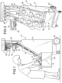
- Figs. 1 and 2 show an exemplary centrifugal processing system 10 that employs a centrifuge assembly 12 of the present disclosure.
- the system 10 can be used for processing various fluids.
- the system 10 is particularly well suited for processing whole blood and other suspensions of cellular materials that are subject to trauma.
- the system 10 includes a centrifuge assembly 12 and an associated fluid processing assembly 14.
- the centrifuge assembly 12 is a durable equipment item.
- the fluid processing assembly 14 is a single use, disposable item that the user loads on the centrifuge assembly 12 before beginning a processing procedure (as Fig. 1 generally shows) and removes from the centrifuge assembly 12 upon the completing the procedure.
- the centrifuge assembly 12 comprises a centrifuge 16 mounted for rotation within a cabinet 18. The user maneuvers and transports the cabinet 18 upon the associated wheels 20. It should be appreciated that, due to its compact form, the centrifuge assembly 12 also could be made as a tabletop unit.
- the cabinet 18 includes a sliding drawer 36 that holds the centrifuge 16.
- the processing assembly 14 comprises a processing chamber 22 mounted on the centrifuge 16 for rotation (as Fig. 1 shows).
- An associated fluid circuit 24 conveys fluids to and from the processing chamber 22.
- the fluid circuit 24 has several fluid containers 26.
- Fig. 2 shows, in use, the containers 26 hang from a support pole outside the cabinet 18.
- the fluid circuit 24 transits several peristaltic pumps 28 and clamps 30 on the face of the cabinet 18.
- the fluid circuit 24 enters an access opening 100 leading to the processing chamber 22 mounted within the cabinet 18.
- the fluid circuit 24 preconnects the processing chamber 22 with the containers 26, forming an integral, sterile unit closed to communication with the atmosphere.
- the centrifuge assembly 12 includes a processing controller 32 that coordinates the operation of the centrifuge 16.
- the processing controller 32 preferably uses an input/output terminal 34 to receive and display information relating to the processing procedure.
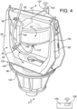
- the centrifuge 16 includes a base 42 that supports a plate 45 mounted upon flexible isolation mounts 44.
- the flexible mounts 44 structurally isolate the components mounted on the plate 45 from the rest of the centrifuge 16, by dampening vibration and oscillation caused by these plate-mounted components.
- the components mounted on the plate 45 make up the isolated mass of the centrifuge 16.
- a nonrotating outer housing or bucket 46 is mounted on the plate 45.
- the bucket 46 encloses a stationary platform 48, which in turn supports the rotating components of the centrifuge 16.
- the rotating components include a centrifuge yoke assembly 50 and a centrifuge chamber assembly 52.
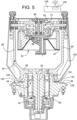
- the yoke assembly 50 rotates upon the platform 48 on a first drive shaft 54.
- the chamber assembly 52 rotates on the yoke assembly 50 on a second drive shaft 56.
- the rotating chamber assembly 52 carries the processing chamber 22.
- the yoke assembly 50 includes a yoke base 58, a pair of upstanding yoke arms 60, and a yoke cross member 62 mounted between the arms 60.
- the base 58 is attached to the first drive shaft 54, which spins on a bearing element 64 about the stationary platform 48.
- a first electric drive 66 rotates the yoke assembly 50 on the first drive shaft 54.
- the chamber assembly 52 is attached to the second drive shaft 56, which spins on a bearing element 68 in the yoke cross member 62.
- the second drive shaft 56 and the bearing element 68 spin as a unit on ball bearings 70.
- a second electric drive 72 rotates the centrifuge chamber assembly 52 on the second drive shaft.
- the first electric drive 66 and the second electric drive 72 each comprises a permanent magnet, brushless DC motor.
- the stationary platform holds the field coils 74 of the first motor 66, while the yoke base 58 comprises the armature or rotor of the first motor 66.
- the yoke cross member 62 holds the field coils 74 of the second motor 72, while the chamber assembly 52 comprises the associated armature or rotor.
- the first electric motor 66 spins the yoke assembly 50 at a predetermined speed of rotation.
- the second electric motor 72 spins the chamber assembly 52 at the same speed of rotation as the first electric motor 66 in the same direction and about the same axis as the spinning yoke assembly 50.
- the yoke assembly 50 includes tube holders 80 and 82 that are carried by yoke cross member 62.
- An active electronic device 103 also is associated with the yoke 50.
- the yoke cross member 62 carries active electronic device 103, such as a sensor that senses or measures a characteristic of the fluid being processed and/or the centrifuge.
- the active electronic device 103 may be a blood component detector, which sensors or detects various blood components and/or their interfaces.
- the active electronic device 103 may be one or more of an interface detector, pressure sensor, temperature sensor, hemolysis sensor, a weight scale or any other suitable electronic device or sensor.
- the active electronic device 103 may include an optical sensor or a camera used to sense or determine characteristics of blood within the centrifuge.
- the active electronic device 103 is powered by a contactless power source 120, such as a wireless power source.
- the contactless power source 120 may include inductive, capacitive, or magneto-dynamic contactless power transfer or any other suitable contactless power transfer.
- the contactless power source 120 includes a power source transmitter 122 and a power source receiver 124.
- the power source transmitter 122 is associated with the stationary platform 48 upon which the yoke assembly rotates.
- the power source transmitter 122 is a relatively flat plate which is associated with a surface 126 of the platform 48 facing the yoke 50.
- the power source transmitter 122 may be located on or embedded in surface 126.
- the power source receiver 124 is associated with a rotating component of the centrifuge 16, such as the rotating yoke 50.
- the power source receiver 124 is a relatively flat plate that is associated with a surface 128 of the rotating yoke 50 facing the stationary platform 48.
- the power source receiver 124 may be located on or embedded in surface 128.
- the active electronic device 103 is powered by the contactless power source 120.
- the active electronic device 103 is operatively connected to the power source receiver 124 by one or more wires 130.
- the wire(s) 130 are shown in broken-line to indicate that they are located or run within the structures of the rotating yoke 50. In other embodiments, the wire(s) 130 may run along the outer surfaces of the rotating yoke 50.
- the rotating yoke 50 rotates relative to the stationary platform 48.
- the power source transmitter 122 on the stationary platform transmits energy to the power source receiver 124.
- the power source receiver 124 powers the active electronic device 103, which may be sensor. In one embodiment, the active electronic device may be electric drive 72.
- the active electronic device 103 may exchange data wirelessly with another device 105 that is not located on the rotating component of the centrifuge.
- the other device 105 is not located on or associated with yoke 50.
- the other device 105 may be for example the controller 32 or in the controller 32 ( Fig. 1 ) which not located on the rotating component.
- the active electronic device 103 may have a wireless data exchange device 107 that exchanges (sends and/or receives) data a separate data exchange device 109 of the other device 105.
- the data may be exchanged via one or more of Bluetooth, Wi-Fi, near field communication or any other suitable wireless peer-to-peer communication.
- the electronic device 103 and the other device 105 also may convert analog data to digital data for wireless transmission.
- the combination of the use of the contactless power source 120 and the wireless data exchange results in the ability to use an active electronic device 103 on the rotating component of the centrifuge with little or no mechanical connections. This configuration achieves greater reliability of the active electronic device and less mechanical failures. Furthermore, this combination may be employed in other fields outside of the blood separation. For example, other fields and structures that include an active electronic device on a rotating component.
- the active electronic device may be any suitable device, such as a sensor or detector that provides information regarding the characteristics of the blood or the operation of the centrifuge.
- Fig. 6 illustrates an exemplary active electronic device 103.
- the active electronic device 103 may be an optical sensor 103a that senses the optical characteristics of fluid during the separation process.
- the sensor 103a may be carried by the cross member 62 ( Fig. 4 ) of the rotating yoke 50.
- the sensor 103a includes a light source 76, which emits light that is absorbed by the fluid, for example red blood cells.
- the light source 76 includes a circular array of red light emitting diodes 84.
- RBC red light emitting diodes
- the sensor 103a also includes a light detector 78, which is mounted adjacent to the light source 76.
- the light detector 78 comprises a PIN diode detector, which is located generally in the geometric center of the circular array of light emitting diodes 84.
- the yoke 50 and sensor 103a rotate relative to the platform 48. Furthermore, the centrifuge chamber assembly 52 rotates relative to the sensor 103a.
- the light source 76 directs light onto the chamber assembly 52.
- the chamber assembly 52 is transparent to the light emitted by the source 76 in the region 86.
- the region 86 comprises a window cut out in the chamber assembly 52.
- the remainder of the chamber assembly 52 that lies in the path of the sensor 103a comprises a light absorbing material.
- the light from the source 76 will thereby pass through the transparent region 86 of the chamber assembly 52 every time the rotating chamber assembly 52 and sensor 103a align. The light is reflected back to toward the sensor, where it is sensed by the detector 78.
- the detector 78 will first sense light reflected through a plasma layer. Eventually, a red blood cell layer will enter the optical path of the sensor 103a. The red blood cell layer absorbs light from the source 76 and thereby reduces the previously sensed intensity of the reflected light. The intensity of the reflected light sensed by the detector 78 represents the amount of light from the source 76 that is not absorbed by the red blood cell layer.
- the sensor may exchange data wirelessly with another device that is not located on the rotating component of the centrifuge.
- the other device may be for example the controller 32 which not located on the rotating component.
- the sensor may have a wireless data exchange member that exchanges (sends and/or receives) data a separate data exchange member of a device not physically associated with the rotating component of the centrifuge that includes the sensor.
- Data from the sensor 103a may be wirelessly transmitted to the other device 105.
- data from sensor 103a may be sent to the controller 32, which then adjusts the centrifuge based on the data.
- analog data from the sensor 103a may be digitized before being wirelessly transmitted by wireless exchange device 107 to the controller 32.
- a centrifuge assembly for processing blood and components, comprising: a base; a rotating component that rotates relative to the base; a contactless power source including a power source transmitter associated with the base and a power source receiver associated with the rotating component, wherein the power source transmitter wirelessly transmits power to the power source receiver; and an active electronic device associated with the rotating component and operatively connected to the power source receiver, wherein the power source receiver provides power to the active electronic device.
- Aspect 2 The centrifuge assembly of Aspect 1, wherein the active electronic device exchanges data with another device that is not located on the rotating component.
- Aspect 3 The centrifuge assembly of Aspect 2, wherein the active electronic device wirelessly exchanges data with the another device not located on the rotating component.
- Aspect 4 The centrifuge assembly of Aspect 3, wherein wireless exchange of data is via one or more of Bluetooth, Wi-Fi, and near field communication.
- Aspect 5 The centrifuge assembly of any one of Aspects 3 and 4, wherein the active electronic device includes a first wireless data exchange device and the another device not located on the rotating component includes a second wireless data exchange device, wherein the first and second wireless data exchange devices exchange data with one another.
- Aspect 6 The centrifuge assembly of any one of Aspects 2-5, wherein the another device not located on the rotating component comprises a controller.
- Aspect 7 The centrifuge assembly of any one of Aspects 1-6, wherein the active electronic device comprises a sensor.
- Aspect 8 The centrifuge assembly of Aspect 7, wherein the sensor senses one or more characteristics of blood and/or blood components.
- Aspect 9 The centrifuge assembly of Aspect 8, wherein the sensor comprises an optical sensor.
- Aspect 10 The centrifuge assembly of Aspect 7, wherein the sensor senses one or more characteristics of the centrifuge assembly.
- Aspect 11 The centrifuge assembly of any one of Aspects 1-6, wherein the active electronic device comprises one or more of a blood component detector, an interface detector, pressure sensor, temperature sensor, hemolysis sensor, weight scale and camera.
- a method of processing blood and/or components with a centrifuge assembly comprising: flowing blood and/or blood components to a rotating component of a centrifuge assembly; rotating the rotating component of the centrifuge assembly relative to a base; and powering an active electronic device associated with the rotating component with a contactless power source.
- Aspect 13 The method of Aspect 12, wherein the contactless power source includes a power source transmitter and a power source receiver, wherein the power source transmitter is associated with the base and the power source receiver is associated with the rotating component; and wherein the power source receiver provides power to the active electronic device.
- Aspect 14 The method of any one of Aspects 12 and 13, further including exchanging data between the active electronic device and another device not located on the rotating component.
- Aspect 15 The method of Aspect 14, wherein the exchanging of data between the active electronic device and the another device comprises wirelessly exchanging data.
- Aspect 16 The method of Aspect 15, wherein wireless exchange of data is via one or more of Bluetooth, Wi-Fi, and near field communication.
- Aspect 17 The method of any one of Aspects 15 and 16, wherein the active electronic device includes a first wireless data exchange device and the another device not located on the rotating component includes a second wireless data exchange device, wherein the first and second wireless data exchange devices exchange data with one another.
- Aspect 18 The method of any one of Aspects 14-17, wherein the another device not located on the rotating component comprises a controller.
- Aspect 19 The method of any one of Aspects 12-18, wherein the active electronic device comprises a sensor.
- Aspect 20 The method of Aspect 19, wherein the sensor senses one or more characteristics of blood and/or blood components.
- Aspect 21 The method of any one of Aspects 19 and 20, wherein the sensor comprises an optical sensor.
- Aspect 22 The method of Aspect 19, wherein the sensor senses one or more characteristics of the centrifuge assembly.
- Aspect 23 The method of any one of Aspects 12-18, wherein the active electronic device comprises one or more of a blood component detector, an interface detector, pressure sensor, temperature sensor, hemolysis sensor, weight scale, and camera.
Landscapes
- Health & Medical Sciences (AREA)
- Vascular Medicine (AREA)
- Heart & Thoracic Surgery (AREA)
- Engineering & Computer Science (AREA)
- Life Sciences & Earth Sciences (AREA)
- Public Health (AREA)
- Biomedical Technology (AREA)
- Hematology (AREA)
- Cardiology (AREA)
- Animal Behavior & Ethology (AREA)
- General Health & Medical Sciences (AREA)
- Anesthesiology (AREA)
- Veterinary Medicine (AREA)
- Computer Networks & Wireless Communication (AREA)
- Power Engineering (AREA)
- Centrifugal Separators (AREA)
- External Artificial Organs (AREA)
- Arrangements For Transmission Of Measured Signals (AREA)
Applications Claiming Priority (1)
| Application Number | Priority Date | Filing Date | Title |
|---|---|---|---|
| US202263320898P | 2022-03-17 | 2022-03-17 |
Publications (2)
| Publication Number | Publication Date |
|---|---|
| EP4245331A1 true EP4245331A1 (de) | 2023-09-20 |
| EP4245331B1 EP4245331B1 (de) | 2026-05-06 |
Family
ID=85640837
Family Applications (1)
| Application Number | Title | Priority Date | Filing Date |
|---|---|---|---|
| EP23161710.1A Active EP4245331B1 (de) | 2022-03-17 | 2023-03-14 | Zentrifuge mit kontaktloser energiequelle für eine elektronische aktive vorrichtung |
Country Status (3)
| Country | Link |
|---|---|
| US (1) | US20230294111A1 (de) |
| EP (1) | EP4245331B1 (de) |
| JP (1) | JP2023138436A (de) |
Citations (4)
| Publication number | Priority date | Publication date | Assignee | Title |
|---|---|---|---|---|
| WO2003000380A1 (en) * | 2001-06-20 | 2003-01-03 | Medicept, Inc. | Blood component preparation (bcp) device and method of use thereof |
| WO2004018021A2 (en) * | 2002-08-23 | 2004-03-04 | Gambro, Inc. | Methods and apparatuses for blood component separation |
| WO2008105972A1 (en) * | 2007-02-26 | 2008-09-04 | Caridianbct, Inc. | Apparatus for separating a composite liquid with process control on a centrifuge rotor |
| WO2021148831A1 (en) * | 2020-01-23 | 2021-07-29 | Total Se | Centrifuge rotor for centrifuging a sample, related centrifuge and measurement method |
Family Cites Families (3)
| Publication number | Priority date | Publication date | Assignee | Title |
|---|---|---|---|---|
| US5525218A (en) * | 1993-10-29 | 1996-06-11 | Baxter International Inc. | Centrifuge with separable bowl and spool elements providing access to the separation chamber |
| WO2012009177A1 (en) * | 2010-07-15 | 2012-01-19 | Caridianbct, Inc. | Method for optimizing spin time in a centrifuge apparatus for biologic fluids |
| US10286148B2 (en) * | 2012-01-23 | 2019-05-14 | Fenwal, Inc. | Using physiological data in a medical device |
-
2023
- 2023-03-14 JP JP2023039232A patent/JP2023138436A/ja active Pending
- 2023-03-14 EP EP23161710.1A patent/EP4245331B1/de active Active
- 2023-03-14 US US18/183,662 patent/US20230294111A1/en active Pending
Patent Citations (4)
| Publication number | Priority date | Publication date | Assignee | Title |
|---|---|---|---|---|
| WO2003000380A1 (en) * | 2001-06-20 | 2003-01-03 | Medicept, Inc. | Blood component preparation (bcp) device and method of use thereof |
| WO2004018021A2 (en) * | 2002-08-23 | 2004-03-04 | Gambro, Inc. | Methods and apparatuses for blood component separation |
| WO2008105972A1 (en) * | 2007-02-26 | 2008-09-04 | Caridianbct, Inc. | Apparatus for separating a composite liquid with process control on a centrifuge rotor |
| WO2021148831A1 (en) * | 2020-01-23 | 2021-07-29 | Total Se | Centrifuge rotor for centrifuging a sample, related centrifuge and measurement method |
Non-Patent Citations (1)
| Title |
|---|
| KINAHAN DAVID J ET AL: "Wireless closed-loop control of centrifugo-pneumatic valving towards large-scale microfluidic process integration", 2018 IEEE MICRO ELECTRO MECHANICAL SYSTEMS (MEMS), IEEE, 21 January 2018 (2018-01-21), pages 1213 - 1216, XP033335853, DOI: 10.1109/MEMSYS.2018.8346781 * |
Also Published As
| Publication number | Publication date |
|---|---|
| JP2023138436A (ja) | 2023-10-02 |
| US20230294111A1 (en) | 2023-09-21 |
| EP4245331B1 (de) | 2026-05-06 |
Similar Documents
| Publication | Publication Date | Title |
|---|---|---|
| EP3515524B1 (de) | Blutpumpe mit sensoren auf der gehäuseoberfläche | |
| US12070592B2 (en) | Pump having a rotor sensor for detecting physiological parameters, flow parameters, and movement parameters | |
| CN103260666B (zh) | 可植入血泵用控制器和电源 | |
| US9127680B2 (en) | Verification of magnetic balance for magnetically levitated impeller | |
| EP1495773B1 (de) | Kreiselpumpe | |
| US6152704A (en) | Blood pump with turbine drive | |
| US20180110910A1 (en) | Pump arrangement and method of operating a fluid pump | |
| JP4879016B2 (ja) | 血液成分分離装置 | |
| CN109152923B (zh) | 用于使外部元件相对于可植入医疗设备对准的对中套件 | |
| JP2003201992A (ja) | 遠心式液体ポンプ装置 | |
| US20230294111A1 (en) | Centrifuge with contactless power source for active electronic device | |
| CN106199556A (zh) | 一种自主驾驶用车载激光雷达的旋转扫描装置 | |
| JPS63502451A (ja) | 光学的データ収集装置 | |
| WO2006070350A2 (en) | Motor for an in-vivo device | |
| JP2021127765A (ja) | ポンプ・デバイス、使い捨てデバイス、及びポンプ・デバイスの作動方法 | |
| US5683341A (en) | Quill shaft suspension for centrifuge rotor having central stator | |
| CN105954738A (zh) | 一种直驱小型旋转扫描测距装置 | |
| US20200036299A1 (en) | Bearing-Less Electrostatic Flywheel | |
| CN206132998U (zh) | 磁悬浮光学扫描测距装置 | |
| US10281443B2 (en) | Gas detection device | |
| US20220266264A1 (en) | Centrifuge | |
| CN219815031U (zh) | 一种固定轴及血泵 | |
| JP2002039088A (ja) | 回転体装置 | |
| CN211602255U (zh) | 一种压缩机扭矩传感器 | |
| CN117529345A (zh) | 用于检测吸奶器特性的系统 |
Legal Events
| Date | Code | Title | Description |
|---|---|---|---|
| PUAI | Public reference made under article 153(3) epc to a published international application that has entered the european phase |
Free format text: ORIGINAL CODE: 0009012 |
|
| STAA | Information on the status of an ep patent application or granted ep patent |
Free format text: STATUS: THE APPLICATION HAS BEEN PUBLISHED |
|
| AK | Designated contracting states |
Kind code of ref document: A1 Designated state(s): AL AT BE BG CH CY CZ DE DK EE ES FI FR GB GR HR HU IE IS IT LI LT LU LV MC ME MK MT NL NO PL PT RO RS SE SI SK SM TR |
|
| STAA | Information on the status of an ep patent application or granted ep patent |
Free format text: STATUS: REQUEST FOR EXAMINATION WAS MADE |
|
| 17P | Request for examination filed |
Effective date: 20240228 |
|
| RBV | Designated contracting states (corrected) |
Designated state(s): AL AT BE BG CH CY CZ DE DK EE ES FI FR GB GR HR HU IE IS IT LI LT LU LV MC ME MK MT NL NO PL PT RO RS SE SI SK SM TR |
|
| STAA | Information on the status of an ep patent application or granted ep patent |
Free format text: STATUS: EXAMINATION IS IN PROGRESS |
|
| 17Q | First examination report despatched |
Effective date: 20250626 |
|
| GRAP | Despatch of communication of intention to grant a patent |
Free format text: ORIGINAL CODE: EPIDOSNIGR1 |
|
| STAA | Information on the status of an ep patent application or granted ep patent |
Free format text: STATUS: GRANT OF PATENT IS INTENDED |
|
| RIC1 | Information provided on ipc code assigned before grant |
Ipc: A61M 1/36 20060101AFI20251215BHEP Ipc: B04B 13/00 20060101ALI20251215BHEP Ipc: B04B 5/04 20060101ALI20251215BHEP |
|
| INTG | Intention to grant announced |
Effective date: 20260121 |
|
| GRAS | Grant fee paid |
Free format text: ORIGINAL CODE: EPIDOSNIGR3 |
|
| GRAA | (expected) grant |
Free format text: ORIGINAL CODE: 0009210 |
|
| STAA | Information on the status of an ep patent application or granted ep patent |
Free format text: STATUS: THE PATENT HAS BEEN GRANTED |
|
| AK | Designated contracting states |
Kind code of ref document: B1 Designated state(s): AL AT BE BG CH CY CZ DE DK EE ES FI FR GB GR HR HU IE IS IT LI LT LU LV MC ME MK MT NL NO PL PT RO RS SE SI SK SM TR |
|
| REG | Reference to a national code |
Ref country code: CH Ref legal event code: F10 Free format text: ST27 STATUS EVENT CODE: U-0-0-F10-F00 (AS PROVIDED BY THE NATIONAL OFFICE) Effective date: 20260506 Ref country code: GB Ref legal event code: FG4D |