EP4245222A1 - System and method for patient-ventilator synchronization/onset detection utilizing time-frequency analysis of emg signals - Google Patents
System and method for patient-ventilator synchronization/onset detection utilizing time-frequency analysis of emg signals Download PDFInfo
- Publication number
- EP4245222A1 EP4245222A1 EP23159863.2A EP23159863A EP4245222A1 EP 4245222 A1 EP4245222 A1 EP 4245222A1 EP 23159863 A EP23159863 A EP 23159863A EP 4245222 A1 EP4245222 A1 EP 4245222A1
- Authority
- EP
- European Patent Office
- Prior art keywords
- components
- patient
- onset
- emg
- processor
- Prior art date
- Legal status (The legal status is an assumption and is not a legal conclusion. Google has not performed a legal analysis and makes no representation as to the accuracy of the status listed.)
- Pending
Links
Images






Classifications
-
- A—HUMAN NECESSITIES
- A61—MEDICAL OR VETERINARY SCIENCE; HYGIENE
- A61B—DIAGNOSIS; SURGERY; IDENTIFICATION
- A61B5/00—Measuring for diagnostic purposes; Identification of persons
- A61B5/48—Other medical applications
- A61B5/4836—Diagnosis combined with treatment in closed-loop systems or methods
- A61B5/4839—Diagnosis combined with treatment in closed-loop systems or methods combined with drug delivery
-
- A—HUMAN NECESSITIES
- A61—MEDICAL OR VETERINARY SCIENCE; HYGIENE
- A61M—DEVICES FOR INTRODUCING MEDIA INTO, OR ONTO, THE BODY; DEVICES FOR TRANSDUCING BODY MEDIA OR FOR TAKING MEDIA FROM THE BODY; DEVICES FOR PRODUCING OR ENDING SLEEP OR STUPOR
- A61M16/00—Devices for influencing the respiratory system of patients by gas treatment, e.g. ventilators; Tracheal tubes
- A61M16/021—Devices for influencing the respiratory system of patients by gas treatment, e.g. ventilators; Tracheal tubes operated by electrical means
- A61M16/022—Control means therefor
- A61M16/024—Control means therefor including calculation means, e.g. using a processor
- A61M16/026—Control means therefor including calculation means, e.g. using a processor specially adapted for predicting, e.g. for determining an information representative of a flow limitation during a ventilation cycle by using a root square technique or a regression analysis
-
- A—HUMAN NECESSITIES
- A61—MEDICAL OR VETERINARY SCIENCE; HYGIENE
- A61B—DIAGNOSIS; SURGERY; IDENTIFICATION
- A61B5/00—Measuring for diagnostic purposes; Identification of persons
- A61B5/24—Detecting, measuring or recording bioelectric or biomagnetic signals of the body or parts thereof
- A61B5/30—Input circuits therefor
- A61B5/307—Input circuits therefor specially adapted for particular uses
- A61B5/313—Input circuits therefor specially adapted for particular uses for electromyography [EMG]
-
- A—HUMAN NECESSITIES
- A61—MEDICAL OR VETERINARY SCIENCE; HYGIENE
- A61B—DIAGNOSIS; SURGERY; IDENTIFICATION
- A61B5/00—Measuring for diagnostic purposes; Identification of persons
- A61B5/24—Detecting, measuring or recording bioelectric or biomagnetic signals of the body or parts thereof
- A61B5/316—Modalities, i.e. specific diagnostic methods
- A61B5/389—Electromyography [EMG]
-
- A—HUMAN NECESSITIES
- A61—MEDICAL OR VETERINARY SCIENCE; HYGIENE
- A61B—DIAGNOSIS; SURGERY; IDENTIFICATION
- A61B5/00—Measuring for diagnostic purposes; Identification of persons
- A61B5/24—Detecting, measuring or recording bioelectric or biomagnetic signals of the body or parts thereof
- A61B5/316—Modalities, i.e. specific diagnostic methods
- A61B5/389—Electromyography [EMG]
- A61B5/397—Analysis of electromyograms
-
- A—HUMAN NECESSITIES
- A61—MEDICAL OR VETERINARY SCIENCE; HYGIENE
- A61B—DIAGNOSIS; SURGERY; IDENTIFICATION
- A61B5/00—Measuring for diagnostic purposes; Identification of persons
- A61B5/72—Signal processing specially adapted for physiological signals or for diagnostic purposes
- A61B5/7203—Signal processing specially adapted for physiological signals or for diagnostic purposes for noise prevention, reduction or removal
-
- A—HUMAN NECESSITIES
- A61—MEDICAL OR VETERINARY SCIENCE; HYGIENE
- A61B—DIAGNOSIS; SURGERY; IDENTIFICATION
- A61B5/00—Measuring for diagnostic purposes; Identification of persons
- A61B5/72—Signal processing specially adapted for physiological signals or for diagnostic purposes
- A61B5/7235—Details of waveform analysis
- A61B5/7246—Details of waveform analysis using correlation, e.g. template matching or determination of similarity
-
- A—HUMAN NECESSITIES
- A61—MEDICAL OR VETERINARY SCIENCE; HYGIENE
- A61B—DIAGNOSIS; SURGERY; IDENTIFICATION
- A61B5/00—Measuring for diagnostic purposes; Identification of persons
- A61B5/72—Signal processing specially adapted for physiological signals or for diagnostic purposes
- A61B5/7235—Details of waveform analysis
- A61B5/725—Details of waveform analysis using specific filters therefor, e.g. Kalman or adaptive filters
-
- A—HUMAN NECESSITIES
- A61—MEDICAL OR VETERINARY SCIENCE; HYGIENE
- A61B—DIAGNOSIS; SURGERY; IDENTIFICATION
- A61B5/00—Measuring for diagnostic purposes; Identification of persons
- A61B5/72—Signal processing specially adapted for physiological signals or for diagnostic purposes
- A61B5/7235—Details of waveform analysis
- A61B5/7253—Details of waveform analysis characterised by using transforms
- A61B5/726—Details of waveform analysis characterised by using transforms using Wavelet transforms
-
- A—HUMAN NECESSITIES
- A61—MEDICAL OR VETERINARY SCIENCE; HYGIENE
- A61B—DIAGNOSIS; SURGERY; IDENTIFICATION
- A61B5/00—Measuring for diagnostic purposes; Identification of persons
- A61B5/72—Signal processing specially adapted for physiological signals or for diagnostic purposes
- A61B5/7271—Specific aspects of physiological measurement analysis
- A61B5/7275—Determining trends in physiological measurement data; Predicting development of a medical condition based on physiological measurements, e.g. determining a risk factor
-
- A—HUMAN NECESSITIES
- A61—MEDICAL OR VETERINARY SCIENCE; HYGIENE
- A61B—DIAGNOSIS; SURGERY; IDENTIFICATION
- A61B5/00—Measuring for diagnostic purposes; Identification of persons
- A61B5/72—Signal processing specially adapted for physiological signals or for diagnostic purposes
- A61B5/7271—Specific aspects of physiological measurement analysis
- A61B5/7282—Event detection, e.g. detecting unique waveforms indicative of a medical condition
-
- A—HUMAN NECESSITIES
- A61—MEDICAL OR VETERINARY SCIENCE; HYGIENE
- A61M—DEVICES FOR INTRODUCING MEDIA INTO, OR ONTO, THE BODY; DEVICES FOR TRANSDUCING BODY MEDIA OR FOR TAKING MEDIA FROM THE BODY; DEVICES FOR PRODUCING OR ENDING SLEEP OR STUPOR
- A61M16/00—Devices for influencing the respiratory system of patients by gas treatment, e.g. ventilators; Tracheal tubes
- A61M16/021—Devices for influencing the respiratory system of patients by gas treatment, e.g. ventilators; Tracheal tubes operated by electrical means
- A61M16/022—Control means therefor
- A61M16/024—Control means therefor including calculation means, e.g. using a processor
-
- G—PHYSICS
- G16—INFORMATION AND COMMUNICATION TECHNOLOGY [ICT] SPECIALLY ADAPTED FOR SPECIFIC APPLICATION FIELDS
- G16H—HEALTHCARE INFORMATICS, i.e. INFORMATION AND COMMUNICATION TECHNOLOGY [ICT] SPECIALLY ADAPTED FOR THE HANDLING OR PROCESSING OF MEDICAL OR HEALTHCARE DATA
- G16H40/00—ICT specially adapted for the management or administration of healthcare resources or facilities; ICT specially adapted for the management or operation of medical equipment or devices
- G16H40/60—ICT specially adapted for the management or administration of healthcare resources or facilities; ICT specially adapted for the management or operation of medical equipment or devices for the operation of medical equipment or devices
- G16H40/63—ICT specially adapted for the management or administration of healthcare resources or facilities; ICT specially adapted for the management or operation of medical equipment or devices for the operation of medical equipment or devices for local operation
-
- A—HUMAN NECESSITIES
- A61—MEDICAL OR VETERINARY SCIENCE; HYGIENE
- A61M—DEVICES FOR INTRODUCING MEDIA INTO, OR ONTO, THE BODY; DEVICES FOR TRANSDUCING BODY MEDIA OR FOR TAKING MEDIA FROM THE BODY; DEVICES FOR PRODUCING OR ENDING SLEEP OR STUPOR
- A61M16/00—Devices for influencing the respiratory system of patients by gas treatment, e.g. ventilators; Tracheal tubes
- A61M16/10—Preparation of respiratory gases or vapours
- A61M16/12—Preparation of respiratory gases or vapours by mixing different gases
-
- A—HUMAN NECESSITIES
- A61—MEDICAL OR VETERINARY SCIENCE; HYGIENE
- A61M—DEVICES FOR INTRODUCING MEDIA INTO, OR ONTO, THE BODY; DEVICES FOR TRANSDUCING BODY MEDIA OR FOR TAKING MEDIA FROM THE BODY; DEVICES FOR PRODUCING OR ENDING SLEEP OR STUPOR
- A61M16/00—Devices for influencing the respiratory system of patients by gas treatment, e.g. ventilators; Tracheal tubes
- A61M16/10—Preparation of respiratory gases or vapours
- A61M16/14—Preparation of respiratory gases or vapours by mixing different fluids, one of them being in a liquid phase
- A61M16/16—Devices to humidify the respiration air
-
- A—HUMAN NECESSITIES
- A61—MEDICAL OR VETERINARY SCIENCE; HYGIENE
- A61M—DEVICES FOR INTRODUCING MEDIA INTO, OR ONTO, THE BODY; DEVICES FOR TRANSDUCING BODY MEDIA OR FOR TAKING MEDIA FROM THE BODY; DEVICES FOR PRODUCING OR ENDING SLEEP OR STUPOR
- A61M16/00—Devices for influencing the respiratory system of patients by gas treatment, e.g. ventilators; Tracheal tubes
- A61M16/22—Carbon dioxide-absorbing devices ; Other means for removing carbon dioxide
-
- A—HUMAN NECESSITIES
- A61—MEDICAL OR VETERINARY SCIENCE; HYGIENE
- A61M—DEVICES FOR INTRODUCING MEDIA INTO, OR ONTO, THE BODY; DEVICES FOR TRANSDUCING BODY MEDIA OR FOR TAKING MEDIA FROM THE BODY; DEVICES FOR PRODUCING OR ENDING SLEEP OR STUPOR
- A61M16/00—Devices for influencing the respiratory system of patients by gas treatment, e.g. ventilators; Tracheal tubes
- A61M16/0003—Accessories therefor, e.g. sensors, vibrators, negative pressure
- A61M2016/0027—Accessories therefor, e.g. sensors, vibrators, negative pressure pressure meter
-
- A—HUMAN NECESSITIES
- A61—MEDICAL OR VETERINARY SCIENCE; HYGIENE
- A61M—DEVICES FOR INTRODUCING MEDIA INTO, OR ONTO, THE BODY; DEVICES FOR TRANSDUCING BODY MEDIA OR FOR TAKING MEDIA FROM THE BODY; DEVICES FOR PRODUCING OR ENDING SLEEP OR STUPOR
- A61M16/00—Devices for influencing the respiratory system of patients by gas treatment, e.g. ventilators; Tracheal tubes
- A61M16/0003—Accessories therefor, e.g. sensors, vibrators, negative pressure
- A61M2016/003—Accessories therefor, e.g. sensors, vibrators, negative pressure with a flowmeter
- A61M2016/0033—Accessories therefor, e.g. sensors, vibrators, negative pressure with a flowmeter electrical
- A61M2016/0039—Accessories therefor, e.g. sensors, vibrators, negative pressure with a flowmeter electrical in the inspiratory circuit
-
- A—HUMAN NECESSITIES
- A61—MEDICAL OR VETERINARY SCIENCE; HYGIENE
- A61M—DEVICES FOR INTRODUCING MEDIA INTO, OR ONTO, THE BODY; DEVICES FOR TRANSDUCING BODY MEDIA OR FOR TAKING MEDIA FROM THE BODY; DEVICES FOR PRODUCING OR ENDING SLEEP OR STUPOR
- A61M16/00—Devices for influencing the respiratory system of patients by gas treatment, e.g. ventilators; Tracheal tubes
- A61M16/0003—Accessories therefor, e.g. sensors, vibrators, negative pressure
- A61M2016/003—Accessories therefor, e.g. sensors, vibrators, negative pressure with a flowmeter
- A61M2016/0033—Accessories therefor, e.g. sensors, vibrators, negative pressure with a flowmeter electrical
- A61M2016/0042—Accessories therefor, e.g. sensors, vibrators, negative pressure with a flowmeter electrical in the expiratory circuit
-
- A—HUMAN NECESSITIES
- A61—MEDICAL OR VETERINARY SCIENCE; HYGIENE
- A61M—DEVICES FOR INTRODUCING MEDIA INTO, OR ONTO, THE BODY; DEVICES FOR TRANSDUCING BODY MEDIA OR FOR TAKING MEDIA FROM THE BODY; DEVICES FOR PRODUCING OR ENDING SLEEP OR STUPOR
- A61M2202/00—Special media to be introduced, removed or treated
- A61M2202/02—Gases
- A61M2202/0208—Oxygen
-
- A—HUMAN NECESSITIES
- A61—MEDICAL OR VETERINARY SCIENCE; HYGIENE
- A61M—DEVICES FOR INTRODUCING MEDIA INTO, OR ONTO, THE BODY; DEVICES FOR TRANSDUCING BODY MEDIA OR FOR TAKING MEDIA FROM THE BODY; DEVICES FOR PRODUCING OR ENDING SLEEP OR STUPOR
- A61M2205/00—General characteristics of the apparatus
- A61M2205/33—Controlling, regulating or measuring
- A61M2205/3331—Pressure; Flow
- A61M2205/3334—Measuring or controlling the flow rate
-
- A—HUMAN NECESSITIES
- A61—MEDICAL OR VETERINARY SCIENCE; HYGIENE
- A61M—DEVICES FOR INTRODUCING MEDIA INTO, OR ONTO, THE BODY; DEVICES FOR TRANSDUCING BODY MEDIA OR FOR TAKING MEDIA FROM THE BODY; DEVICES FOR PRODUCING OR ENDING SLEEP OR STUPOR
- A61M2230/00—Measuring parameters of the user
- A61M2230/04—Heartbeat characteristics, e.g. ECG, blood pressure modulation
-
- A—HUMAN NECESSITIES
- A61—MEDICAL OR VETERINARY SCIENCE; HYGIENE
- A61M—DEVICES FOR INTRODUCING MEDIA INTO, OR ONTO, THE BODY; DEVICES FOR TRANSDUCING BODY MEDIA OR FOR TAKING MEDIA FROM THE BODY; DEVICES FOR PRODUCING OR ENDING SLEEP OR STUPOR
- A61M2230/00—Measuring parameters of the user
- A61M2230/08—Other bio-electrical signals
-
- A—HUMAN NECESSITIES
- A61—MEDICAL OR VETERINARY SCIENCE; HYGIENE
- A61M—DEVICES FOR INTRODUCING MEDIA INTO, OR ONTO, THE BODY; DEVICES FOR TRANSDUCING BODY MEDIA OR FOR TAKING MEDIA FROM THE BODY; DEVICES FOR PRODUCING OR ENDING SLEEP OR STUPOR
- A61M2230/00—Measuring parameters of the user
- A61M2230/40—Respiratory characteristics
-
- A—HUMAN NECESSITIES
- A61—MEDICAL OR VETERINARY SCIENCE; HYGIENE
- A61M—DEVICES FOR INTRODUCING MEDIA INTO, OR ONTO, THE BODY; DEVICES FOR TRANSDUCING BODY MEDIA OR FOR TAKING MEDIA FROM THE BODY; DEVICES FOR PRODUCING OR ENDING SLEEP OR STUPOR
- A61M2230/00—Measuring parameters of the user
- A61M2230/60—Muscle strain, i.e. measured on the user
Definitions
- the subject matter disclosed herein relates to control of a ventilator.
- the basic modes of ventilator operation can be divided into sub-categories based on whether a ventilator or a patient initiates a breath.
- Patient initiated breathes are referred to as spontaneous breaths.
- a ventilatory action is triggered by a spontaneous breathing event, it is of the utmost importance that the ventilator starts the inhalation process as soon as the patient tries to breathe. In other words, there should be timing synchrony between the patient effort and the ventilator action. It is estimated that in approximately 50 percent of the breaths there is patient-ventilator asynchrony. Any patient-ventilator asynchrony can lead to patient discomfort, sleep disorders, and delay the weaning of the patient.
- a computer-implemented method for detecting onset of a spontaneous breath by a patient coupled to a ventilation system includes receiving, at a processor, an electromyography (EMG) signal from an EMG sensor disposed on the patient.
- EMG electromyography
- the method also includes pre-conditioning, via the processor, the EMG signal to separate the EMG signal into a plurality of components having EMG information utilizing a set of bandpass filters.
- the method further includes individually analyzing, via the processor, each component of the plurality of components to detect an onset of the spontaneous breath by the patient.
- the method still further includes determining, via the processor, the onset of the spontaneous breath by the patient is occurring when at least two components of the plurality of components indicate the onset of the spontaneous breath by the patient.
- a ventilation system in another embodiment, includes a memory encoding processor-executable routines.
- the ventilation system also includes a processor configured to access the memory and to execute the processor-executable routines, wherein the routines, when executed by the processor, cause the processor to perform actions.
- the actions include receiving an electromyography (EMG) signal from an EMG sensor disposed on the patient.
- the actions also include pre-conditioning the EMG signal to separate the EMG signal into a plurality of components having EMG information utilizing a set of bandpass filters.
- the actions further include individually analyzing each component of the plurality of components to detect an onset of the spontaneous breath by the patient.
- the actions still further include determining the onset of the spontaneous breath by the patient is occurring when at least two components of the plurality of components indicate the onset of the spontaneous breath by the patient.
- a non-transitory computer-readable medium includes processor-executable code that when executed by a processor, causes the processor to perform actions.
- the actions include receiving an electromyography (EMG) signal from an EMG sensor disposed on the patient.
- the actions also include pre-conditioning the EMG signal to separate the EMG signal into a plurality of components having EMG information utilizing a set of bandpass filters.
- the actions further include individually analyzing each component of the plurality of components to detect an onset of the spontaneous breath by the patient.
- the actions still further include determining the onset of the spontaneous breath by the patient is occurring when at least two components of the plurality of components indicate the onset of the spontaneous breath by the patient.
- implementations of the present disclosure may be embodied as a system, method, device, or computer program product. Accordingly, aspects of the present disclosure may take the form of an entirely hardware embodiment, an entirely software embodiment (including firmware, resident software, micro-code, etc.) or an embodiment combining software and hardware aspects that may all generally be referred to herein as a "circuit,” “module” or “system.” Furthermore, aspects of the present disclosure may take the form of a computer program product embodied in one or more computer readable medium(s) having computer-readable program code embodied thereon.
- the present disclosure provides systems and methods for detecting the onset of spontaneous breath of a patient coupled to a ventilation system (e.g., mechanical ventilator).
- a ventilation system e.g., mechanical ventilator.
- the disclosed embodiments utilize signals with rich frequency content (e.g., electromyography (EMG) signals) to detect the onset of spontaneous breath by the patient.
- EMG electromyography
- the disclosed embodiments utilize online time-frequency analysis of EMG signals. Online time-frequency analysis is utilized to split the signal into multiple components carrying frequency sub-bands of the original signal.
- Useful components of the signal are identified and a combination of onsets detected (e.g., in two or more identified components) from each of the identified components may be utilized to obtain or detect an onset trigger (i.e., detect the onset of the spontaneous breath) to trigger providing spontaneous breathing support.
- triggering providing spontaneous breathing support may occur upon detecting an onset in one of the identified components and also detecting the onset of spontaneous breath utilizing a different onset detection algorithm.
- the disclosed embodiments may provide for faster and more accurate detection of a patient's effort to breathe.
- the disclosed embodiments may improve the synchronization between the ventilator and the patient.
- the disclosed techniques are discussed with regard to an EMG signal. However, all or some of the disclosed techniques may be utilized on other non-stationary signals with rich frequency content to determine an onset of a spontaneous breath by a patient coupled to a ventilation system.
- FIG. 1 schematically illustrates an example of a mechanical ventilation system 10.
- Ventilation system 10 provides a pneumatic circuit that carries breathing gas to and exhaled air from a patient 11 to assist patient 11 in breathing. As described in greater detail below, the ventilation system is configured to detect the onset of spontaneous breath by the patient 11 in a faster and more accurate manner than typical ventilation systems.
- Ventilation system 10 includes ventilator 12, breathing circuit 14, and sensors 16, 17.
- the ventilator 12 may operate in a number of modes. The modes include a controlled mode (with the breath is initiated by the ventilator 12), a spontaneous mode (where the breath is initiated by the patient), and a supported mode (where the breath is initiated by both the ventilator and patient). Both the spontaneous mode and the supported mode require synchronization with patient effort.
- Ventilator 12 supplies gas, such as air or air including anesthetics, drugs or the like, to patient 11 through breathing circuit 14 and receives exhaled air through breathing circuit 14.
- ventilator 12 receives air from air source 16 through conduit 18 and receives oxygen (O 2 ) from an oxygen source 20 (such as a container of compressed oxygen) through conduit 22.
- the ventilator 12 includes valves 24, 26, sensors 28, 30, valve 32 and sensor 34 and controller or processing unit 36. Valves 24, 26 control a supply of air and oxygen (the mixture thereof), respectively, through conduit 38 to breathing circuit 14.
- Sensors 28 and 30 sense or detect the supply of the air and oxygen, respectively, and transmit signals representing such sensed values to processing unit 36.
- Valve 32 includes a valve mechanism connected to breathing circuit 14 by conduit 40 so as to control the flow of exhaled air received from breathing circuit 14 to the discharge conduit 42.
- Sensor 34 includes a device to sense the flow of exhaled air to discharge port 42. Such sensed values for the exhaled air are further transmitted to controller or processing unit 36.
- Controller 36 generates control signals controlling the operation of valves 24, 26, and 28.
- the controller 36 includes one or more processors 44 and a memory 46.
- the one or more processors 44 executes instructions contained in the memory 46. Execution of the instructions causes the controller 36 to perform steps such as generating control signals.
- the instructions may be loaded in a random access memory (RAM) for execution by the processing unit from a read only memory (ROM), a mass storage device, or some other persistent storage.
- RAM random access memory
- ROM read only memory
- mass storage device or some other persistent storage.
- hard wired circuitry may be used in place of or in combination with software instructions to implement the functions described.
- the processors 44 may be embodied as part of one or more application-specific integrated circuits (ASICs).
- ASICs application-specific integrated circuits
- Breathing circuit 14 delivers breathing gas (air, oxygen and possibly other additives such as anesthetics, medicines and the like) from ventilator 12 to patient 11 while also directing exhaled air from patient 11 to system 10 and ventilator 12.
- Breathing circuit 14 includes inspiratory section or segment 48, expiration segment 50, Y connector 52 and patient segment 54.
- Inspiratory segment 48 extends from and is pneumatically connected to conduit 38 at one end and Y connector 52 at the other end. Segment 48 delivers gases from conduit 38 to patient segment 54 during forced, assisted or voluntary inhalation by patient 11.
- Exhalation segment 50 delivers exhaled gases are exhaled air from patient segment 54 to conduit 40.
- Y connector 52 connects each of segments 48 and 50 to patient segment 54.
- Patient segment 54 extends from Y connector 52 to patient 11.
- Patient segment 54 may include devices for pneumatically connecting with patient 11 such as through the nose, mouth or trachea of patient 11.
- ventilation system 10 may include additional devices or systems.
- system 10 may additionally include a nebulizer positioned between ventilator 12 and inspiratory section 48 to introduce a medical drug or anesthetic agent to breathing air for the patient.
- breathing circuit 14 may include a component such as a humidifier to humidify the breathing air, a heater to heat the breathing air or a water/vapor trap to remove excess moisture from a particular segment or section of ventilation system 10.
- ventilator 12 may additionally include a carbon dioxide scavenger which removes carbon dioxide from exhaled air and returns or recycles the air by conducting such recycled air to conduit 18.
- ventilator 12 utilizes a bellows to pressurize air being supplied to conduit 48.
- ventilator 12 selectively supplies and withdraws pressurized air to and from an exterior of a bellows assembly.
- ventilator12 supplies gas or air to the exterior of the bellows, collapsing the bellows to force gas within bellows to through the carbon dioxide scavenger and to the breathing circuit 14 and the patient's lungs.
- expelled gas from the patient's lungs passes through valve 32 to fill the bellows.
- the noted carbon dioxide scavenger as well as the bellows may be omitted.
- the ventilation system 10 includes a number of noninvasive sensors to be utilized in determining the onset of a breath (e.g., spontaneous breath) of the patient 11.
- some of the sensors may be invasive (e.g., EMG sensor on a catheter passed through the mouth).
- Sensor 16 includes a flow sensor to measure flow and direction of gas or air within a passage (e.g., the patient segment 54).
- Sensor 17 includes a pressure sensor to measure flow within a passage (e.g., the patient segment 54).
- sensors 16, 17 are part of a device configured to sense or detect pressure and/or flow of air (with or without additives) corresponding to forced, voluntary or assisted inhalation and exhalation by patient 11.
- sensor 16 is located within patient segment 54.
- sensor 16 may be provided at other locations.
- sensor 16 may be provided as part of a mouthpiece through which patient 11 inhales and exhales.
- Sensors 16 and 17 provide signals (e.g., flow and pressure signals) to provide feedback to the controller 36.
- the ventilation system 10 includes an EMG sensor 56 (e.g., an EMG patch or surface sensor) disposed on the skin of patient 11 in a location adjacent the upper airway muscles.
- the EMG sensor 56 measures the action potentials of the respiratory muscle.
- the EMG sensor 56 provides an EMG signal to the controller 36.
- the ventilation system 10 also includes an EMG sensor 58 (e.g., an EMG patch or surface sensor) disposed on the skin of patient 11 adjacent the intercostal space.
- the EMG sensor 58 measures the movement of thoracic/abdominal cavity and/or diaphragm.
- the EMG sensor 58 provides an EMG signal to the controller 58.
- an EMG sensor may be placed on the skin on the rear neck region adjacent the posterior cricoarytenoid set of muscles. In certain embodiments, an EMG sensor may be invasive (e.g., via a catheter passed through the mouth).
- the ventilation system 10 includes one or more ECG sensors 60 disposed on the skin of the patient (e.g., in the chest region and/or intercostal space). The ECG sensor 60 measures cardiac electrical activity. The ECG sensor 60 provides the ECG signal to the controller 58.
- the ventilation system 10 includes one or more additional sensors 62 (e.g., ultrasound, piezoelectric, and/or inductance sensors) disposed on the skin of the patient in the chest or intercostal space.
- the sensors 62 measure the movement of the thoracic/abdominal cavity and/or the diaphragm.
- the sensors 62 provides signals to the controller 36.
- the sensors may be connected to the controller 36 via a wired or wireless connection. The measurements from the sensors are synchronized.
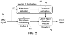
- FIG. 2 is a schematic diagram of the processing of an EMG signal 64 (e.g., raw EMG signal) to determine an onset of a spontaneous breath of a patient coupled to a ventilation system (e.g., ventilation system 10 in FIG. 1 ).
- the processing of the EMG signal 64 to determine the onset of a spontaneous breath of the patient may occur via a number of modules (e.g., stored in and executed by a processing or computing device such as controller 36 in FIG. 1 ).
- the modules include a calibration module 66, a signal pre-conditioning module 68, and an onset trigger detection module 70.
- the calibration module 66 is configured to select filters (e.g., bandpass filters) from a filter bank (as indicated by block 72) to apply to the EMG signal 64 to break the signal 64 into components having useful frequency sub-bands (i.e., having significant EMG information).
- the calibration module 66 is also configured to determine or calibrate thresholds (as indicated by block 74) for each component (e.g., having significant EMG information) of the EMG signal 64.
- the signal pre-conditioning module 68 is configured to separate the EMG signal 64 into multiple components utilizing a set of bandpass filters selected by the calibration module 66. In addition, the signal pre-conditioning module 68 is configured to identify the occurrences of ECG activity and other motion artifacts (e.g., due to body movement) in the EMG signal 64.
- the onset trigger detection module 70 is configured to detect the onset of a spontaneous breath by a patient by individually analyzing each component (e.g., having significant EMG information) for the onset of the spontaneous breath utilizing the thresholds determined or calibrated for each component by the calibration module 66.
- the onset trigger detection module 70 is also configured to determine that the onset of the spontaneous breath by the patient is occurring when analysis of two or more (e.g., 2, 3, 4, etc.) of the components indicate onset of the spontaneous breath.
- the onset trigger detection module 70 is also configured to determine that the onset of the spontaneous breath by the patient is occurring when analysis of one of components indicates onset of the spontaneous breath in combination with a different onset detection algorithm detecting the onset of the spontaneous breath.
- the determination that the onset of the spontaneous breath is occurring results in an onset trigger 76 where a signal is provided to the ventilation system to provide breathing support to synchronize the breathing support with the onset of the spontaneous breath.
- FIG. 3 is a schematic diagram of the calibration process for the EMG signal 64 (e.g., raw EMG signal) utilizing the calibration module 66.
- the calibration module 66 is run once initially and may run again at pre-scheduled intervals (e.g., to update the bandpass filter selection and/or thresholds).
- the calibration module 66 receives the EMG signal 64 and separates or splits the EMG signal 64 into multiple components or levels utilizing a filter bank (block 78). For example, time-frequency analysis may be utilized via application of a discrete wavelet transform (DWT) to decompose the EMG signal 64 into multiple components.
- DWT discrete wavelet transform
- the calibration module 66 then identifies those components with significant or important EMG information (block 80).
- DWT discrete wavelet transform
- Identification of the components having significant information may be identified by looking in each level for correlations between EMG activity and a breathing signature of the patient (e.g., obtained from a pressure sensor and/or a flow sensor of the ventilation system). Low frequency components containing ECG spikes and other motion artifacts (e.g., due to body movement) are ignored.
- the calibration module 66 selects bandpass filters from a filter bank (block 82) that may be utilized by the signal pre-conditioning module 68 to separate the EMG signal into multiple components (e.g., having significant EMG information) in real-time.
- the calibration module 66 determines or calibrates a threshold for each identified component (e.g., having significant EMG information) (block 84).
- the thresholds may be determined utilizing statistical methods and/or a dynamic threshold method.
- FIGS. 4A and 4B schematically illustrate the identification of useful components of the EMG signal 64 (e.g., raw EMG signal) and the pre-conditioning of the EMG signal 64.
- the EMG signal 64 e.g., raw EMG signal
- DWT is applied to the raw EMG signal 64 resulting in decomposing the EMG signal 64 into different components or levels 86.
- Those components or levels having significant EMG information may be identified by looking in each level 86 for correlations between EMG activity and a breathing signature of the patient. For examples, levels 1-5 in FIG. 4A are determined to have significant EMG information (e.g., as indicated by regions 88, 90, 92 in each component 86).
- Low frequency components e.g., level 6 and approximation coefficients
- the components 86 e.g., levels 1-5) of the EMG signal 64 having significant interest after applying the set of band pass filters and their associated frequency bands 94 are depicted in FIG. 4B .
- FIG. 5 is a schematic diagram of the signal pre-conditioning process for the EMG signal 64 utilizing the pre-conditioning module 68 to identify ECG occurrences.
- the signal pre-conditioning module 68 receives the raw EMG signal 64 and splits or separates it into multiple components (block 96) utilizing a filter bank (e.g., DWT filter bank).
- the signal pre-conditioning module 68 then thresholds the components (i.e., compares to a threshold) corresponding to expected interference (block 98).
- the signal pre-conditioning module 68 detect occurrences of ECG activity if the component exceeds the threshold (block 100).
- the occurrences of ECG activity in the EMG signal 64 are provided to the onset trigger detection module 70 to utilize in ignoring false triggers due to residual ECG activity in the analysis of each component of the plurality of components in detecting an onset of the spontaneous breath by the patient.
- FIG. 6 illustrates plots of a raw EMG signal and a filtered EMG signal and respective fast Fourier transforms (FFT) of the raw EMG signal and the filtered EMG signal.
- Plots 102 and 104 are of the raw EMG signal 64 and a filtered EMG signal (e.g., 20 Hz filtered), respectively.
- Plots 106 and 108 are the fast Fourier transforms of the raw EMG signal and the filtered EMG signal, respectively.
- FIG. 7 illustrates a plot 110 illustrating the detection of ECG occurrences and a process 112 for obtaining the plot 110.
- the plot 110 shows ECG spikes 114 present in the raw ECG signal 64.
- the process 112 includes obtaining an FFT of the past 50 millisecond window of the raw EMG signal 64 (block 116).
- the process 112 then includes splitting (e.g. filtering) the FFT of the EMG signal 64 into a band of 0 to 20 Hz (block 118). Then thresholding to detect ECT activity is applied (block 120) to the band.
- FIG. 8 is a schematic diagram of an onset trigger detection process utilizing the onset trigger detection module 70.
- the signal pre-conditioning module 68 splits the raw EMG signal 64 into multiple frequency components 122 (e.g., having significant EMG information) and provides these components 122 to the onset trigger detection module 70.
- the signal pre-conditioning module 68 may provide ECG information (e.g., ECG occurrences) for the EMG signal 64 to the onset trigger detection module 70 to enable ignoring false triggers in detecting onset of a spontaneous breath in the patient due to residual ECG activity.
- the onset trigger detection module 70 detects a respective envelope for each component 122 (block 124).
- the onset trigger detection module 70 analyzes each component by applying respective thresholds 126 (e.g., received from the calibration module 66) to the respective envelope of each of the components 122 to detect the onset of the spontaneous breath for each component 122 (block 128). If the envelope of the component 122 surpasses the respective threshold the onset of the spontaneous breath is detected for that component 122. Finally, the onset detection module 70 utilizes a selection logic to detect the onset to determine the onset of a spontaneous breath of the patient is occurring (block 130). The selection logic details how many of the components 122 detection of the onset of the spontaneous breath must occur in before it is determined the spontaneous breath of the patient is occurring. The number of components 122 onset detection needs to occur in before determining the spontaneous breath is occurring is at least two.
- the number of components 122 onset detection needs to occur in may be three, four, or another number. In certain embodiments, the onset detection may need to occur in each component 122 (e.g., having significant EMG information). In certain embodiments, it may be determined that the onset of the spontaneous breath by the patient is occurring when analysis of one of components indicates onset of the spontaneous breath in combination with a different onset detection algorithm detecting the onset of the spontaneous breath. The determination that the onset of the spontaneous breath is occurring results in the onset trigger 76 (e.g., final onset trigger) where a signal is provided to the ventilation system to provide breathing support to synchronize the breathing support with the onset of the spontaneous breath.
- the onset trigger 76 e.g., final onset trigger
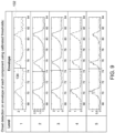
- FIG. 9 illustrates utilizing calibrated thresholds for onset detection on components of the EMG signal 64.
- FIG. 9 depicts the envelope 132 for each component (e.g., levels 1-5 in FIGS. 4A and 4B ) and an indication 134 (e.g., line) along each envelope 132 where onset detection occurs by applying the respective threshold to each envelope 132.
- the onset detection first occurs in level 2 followed by level 3 and then rest of the levels (levels 4, 5, and 1). Once the onset detection occurs in a second level (e.g., level 3), the final onset trigger occurs.
- FIG. 10 illustrates the relative onset time of detection of onset of a breath for a number of breaths in multiple components of an EMG signal.
- Graph 136 includes plots 138, 140, 142, 144, and 146 for levels 1, 2, 3, 4, and 5, respectively, over a number of breaths (e.g., 27 breaths).
- the graph 136 includes a y-axis 148 representing normalized onset time (normalized across levels for each breath) and an x-axis 150 representing the breath number.
- the onset time for each level varies from breath to breath. Utilizing a combination of the component-wise onsets enables for faster and more accurate onset detection of the occurrence of a spontaneous breath.
- inventions include utilizing signals with rich frequency content (e.g., EMG signals) to detect the onset of spontaneous breath by the patient via online time-frequency analysis of EMG signals.
- Useful components of the EMG signal are identified and a combination of onsets detected (e.g., in two or more identified components) from each of the identified components may be utilized to obtain or detect an onset trigger (i.e., detect the onset of the spontaneous breath) to trigger providing breathing support to the patient.
- the disclosed embodiments may provide for faster and more accurate detection of a patient's effort to breathe.
- the disclosed embodiments may improve the synchronization between the ventilator and the patient.
Landscapes
- Health & Medical Sciences (AREA)
- Life Sciences & Earth Sciences (AREA)
- Engineering & Computer Science (AREA)
- Biomedical Technology (AREA)
- Public Health (AREA)
- General Health & Medical Sciences (AREA)
- Veterinary Medicine (AREA)
- Animal Behavior & Ethology (AREA)
- Heart & Thoracic Surgery (AREA)
- Medical Informatics (AREA)
- Biophysics (AREA)
- Pathology (AREA)
- Physics & Mathematics (AREA)
- Molecular Biology (AREA)
- Surgery (AREA)
- Signal Processing (AREA)
- Psychiatry (AREA)
- Physiology (AREA)
- Computer Vision & Pattern Recognition (AREA)
- Artificial Intelligence (AREA)
- Anesthesiology (AREA)
- Pulmonology (AREA)
- Hematology (AREA)
- Emergency Medicine (AREA)
- Business, Economics & Management (AREA)
- General Business, Economics & Management (AREA)
- Epidemiology (AREA)
- Primary Health Care (AREA)
- Chemical & Material Sciences (AREA)
- Bioinformatics & Cheminformatics (AREA)
- Medicinal Chemistry (AREA)
- Pharmacology & Pharmacy (AREA)
- Measurement Of The Respiration, Hearing Ability, Form, And Blood Characteristics Of Living Organisms (AREA)
Abstract
A computer-implemented method for detecting onset of a spontaneous breath by a patient coupled to a ventilation system (10) includes receiving, at a processor (44), an electromyography (EMG) signal from an EMG sensor (56, 58) disposed on the patient. The method also includes pre-conditioning, via the processor (44), the EMG signal (64) to separate the EMG signal (64) into a plurality of components (86) having EMG information utilizing a set of bandpass filters. The method further includes individually analyzing, via the processor (44), each component (86) of the plurality of components (86) to detect an onset of the spontaneous breath by the patient. The method still further includes determining, via the processor (44), the onset of the spontaneous breath by the patient is occurring when at least two components (86) of the plurality of components (86) indicate the onset of the spontaneous breath by the patient.
Description
- The subject matter disclosed herein relates to control of a ventilator.
- The basic modes of ventilator operation can be divided into sub-categories based on whether a ventilator or a patient initiates a breath. Patient initiated breathes are referred to as spontaneous breaths. When a ventilatory action is triggered by a spontaneous breathing event, it is of the utmost importance that the ventilator starts the inhalation process as soon as the patient tries to breathe. In other words, there should be timing synchrony between the patient effort and the ventilator action. It is estimated that in approximately 50 percent of the breaths there is patient-ventilator asynchrony. Any patient-ventilator asynchrony can lead to patient discomfort, sleep disorders, and delay the weaning of the patient. Currently, there is a delay (e.g., a few hundreds of milliseconds delay) between when the diaphragm of the patient starts muscle activation to when it leads to a change in pressure and flow at the facial region. Thus, there is a need to detect the start of inhalation effort by the patient earlier and to improve the synchronization between the patient and the ventilator during spontaneous breaths.
- Certain embodiments commensurate in scope with the originally claimed subject matter are summarized below. These embodiments are not intended to limit the scope of the claimed subject matter, but rather these embodiments are intended only to provide a brief summary of possible embodiments. Indeed, the invention may encompass a variety of forms that may be similar to or different from the embodiments set forth below.
- In one embodiment, a computer-implemented method for detecting onset of a spontaneous breath by a patient coupled to a ventilation system is provided. The method includes receiving, at a processor, an electromyography (EMG) signal from an EMG sensor disposed on the patient. The method also includes pre-conditioning, via the processor, the EMG signal to separate the EMG signal into a plurality of components having EMG information utilizing a set of bandpass filters. The method further includes individually analyzing, via the processor, each component of the plurality of components to detect an onset of the spontaneous breath by the patient. The method still further includes determining, via the processor, the onset of the spontaneous breath by the patient is occurring when at least two components of the plurality of components indicate the onset of the spontaneous breath by the patient.
- In another embodiment, a ventilation system is provided. The ventilation system includes a memory encoding processor-executable routines. The ventilation system also includes a processor configured to access the memory and to execute the processor-executable routines, wherein the routines, when executed by the processor, cause the processor to perform actions. The actions include receiving an electromyography (EMG) signal from an EMG sensor disposed on the patient. The actions also include pre-conditioning the EMG signal to separate the EMG signal into a plurality of components having EMG information utilizing a set of bandpass filters. The actions further include individually analyzing each component of the plurality of components to detect an onset of the spontaneous breath by the patient. The actions still further include determining the onset of the spontaneous breath by the patient is occurring when at least two components of the plurality of components indicate the onset of the spontaneous breath by the patient.
- In a further embodiment, a non-transitory computer-readable medium is provided. The computer-readable medium includes processor-executable code that when executed by a processor, causes the processor to perform actions. The actions include receiving an electromyography (EMG) signal from an EMG sensor disposed on the patient. The actions also include pre-conditioning the EMG signal to separate the EMG signal into a plurality of components having EMG information utilizing a set of bandpass filters. The actions further include individually analyzing each component of the plurality of components to detect an onset of the spontaneous breath by the patient. The actions still further include determining the onset of the spontaneous breath by the patient is occurring when at least two components of the plurality of components indicate the onset of the spontaneous breath by the patient.
- These and other features, aspects, and advantages of the present subject matter will become better understood when the following detailed description is read with reference to the accompanying drawings in which like characters represent like parts throughout the drawings, wherein:
-
FIG. 1 is a schematic diagram of a mechanical ventilation system, in accordance with aspects of the present disclosure; -
FIG. 2 is a schematic diagram of the processing of an EMG signal to determine an onset of a spontaneous breath of a patient coupled to a ventilation system, in accordance with aspects of the present disclosure; -
FIG. 3 is a schematic diagram of the calibration process for an EMG signal utilizing a calibration module, in accordance with aspects of the present disclosure; -
FIGS. 4A and4B are a schematic diagram illustrating the identification of useful components of an EMG signal and the pre-conditioning of the EMG signal, in accordance with aspects of the present disclosure; -
FIG. 5 is a schematic diagram of the pre-conditioning process for an EMG signal utilizing a signal pre-conditioning module to identify electrocardiogram (ECG) occurrences, in accordance with aspects of the present disclosure; -
FIG. 6 illustrates plots of a raw EMG signal and a filtered EMG signal and respective fast Fourier transforms (FFT) of the raw EMG signal and the filtered EMG signal, in accordance with aspects of the present disclosure; -
FIG. 7 illustrates a plot illustrating the detection of ECG occurrences and a process for obtaining the plot, in accordance with aspects of the present disclosure; -
FIG. 8 is a schematic diagram of an onset trigger detection process utilizing an onset trigger detection module, in accordance with aspects of the present disclosure; -
FIG. 9 illustrates utilizing calibrated thresholds for onset detection on components of an EMG signal, in accordance with aspects of the present disclosure; and -
FIG. 10 illustrates the detection the relative onset time of onset of a breath for a number of breaths in multiple components of an EMG signal, in accordance with aspects of the present disclosure. - One or more specific embodiments will be described below. In an effort to provide a concise description of these embodiments, not all features of an actual implementation are described in the specification. It should be appreciated that in the development of any such actual implementation, as in any engineering or design project, numerous implementation-specific decisions must be made to achieve the developers' specific goals, such as compliance with system-related and business-related constraints, which may vary from one implementation to another. Moreover, it should be appreciated that such a development effort might be complex and time consuming, but would nevertheless be a routine undertaking of design, fabrication, and manufacture for those of ordinary skill having the benefit of this disclosure.
- When introducing elements of various embodiments of the present subject matter, the articles "a," "an," "the," and "said" are intended to mean that there are one or more of the elements. The terms "comprising," "including," and "having" are intended to be inclusive and mean that there may be additional elements other than the listed elements. Furthermore, any numerical examples in the following discussion are intended to be nonlimiting, and thus additional numerical values, ranges, and percentages are within the scope of the disclosed embodiments.
- As may be appreciated, implementations of the present disclosure may be embodied as a system, method, device, or computer program product. Accordingly, aspects of the present disclosure may take the form of an entirely hardware embodiment, an entirely software embodiment (including firmware, resident software, micro-code, etc.) or an embodiment combining software and hardware aspects that may all generally be referred to herein as a "circuit," "module" or "system." Furthermore, aspects of the present disclosure may take the form of a computer program product embodied in one or more computer readable medium(s) having computer-readable program code embodied thereon.
- The present disclosure provides systems and methods for detecting the onset of spontaneous breath of a patient coupled to a ventilation system (e.g., mechanical ventilator). The disclosed embodiments utilize signals with rich frequency content (e.g., electromyography (EMG) signals) to detect the onset of spontaneous breath by the patient. In particular, the disclosed embodiments utilize online time-frequency analysis of EMG signals. Online time-frequency analysis is utilized to split the signal into multiple components carrying frequency sub-bands of the original signal. Useful components of the signal are identified and a combination of onsets detected (e.g., in two or more identified components) from each of the identified components may be utilized to obtain or detect an onset trigger (i.e., detect the onset of the spontaneous breath) to trigger providing spontaneous breathing support. In certain embodiments, triggering providing spontaneous breathing support may occur upon detecting an onset in one of the identified components and also detecting the onset of spontaneous breath utilizing a different onset detection algorithm. The disclosed embodiments may provide for faster and more accurate detection of a patient's effort to breathe. In addition, the disclosed embodiments may improve the synchronization between the ventilator and the patient.
- The disclosed techniques are discussed with regard to an EMG signal. However, all or some of the disclosed techniques may be utilized on other non-stationary signals with rich frequency content to determine an onset of a spontaneous breath by a patient coupled to a ventilation system.
-
FIG. 1 schematically illustrates an example of amechanical ventilation system 10.Ventilation system 10 provides a pneumatic circuit that carries breathing gas to and exhaled air from a patient 11 to assistpatient 11 in breathing. As described in greater detail below, the ventilation system is configured to detect the onset of spontaneous breath by the patient 11 in a faster and more accurate manner than typical ventilation systems.Ventilation system 10 includesventilator 12, breathingcircuit 14, andsensors ventilator 12 may operate in a number of modes. The modes include a controlled mode (with the breath is initiated by the ventilator 12), a spontaneous mode (where the breath is initiated by the patient), and a supported mode (where the breath is initiated by both the ventilator and patient). Both the spontaneous mode and the supported mode require synchronization with patient effort. -
Ventilator 12 supplies gas, such as air or air including anesthetics, drugs or the like, to patient 11 throughbreathing circuit 14 and receives exhaled air throughbreathing circuit 14. In the example illustrated,ventilator 12 receives air fromair source 16 throughconduit 18 and receives oxygen (O2) from an oxygen source 20 (such as a container of compressed oxygen) throughconduit 22. Theventilator 12 includesvalves sensors valve 32 andsensor 34 and controller orprocessing unit 36.Valves conduit 38 to breathingcircuit 14.Sensors unit 36. -
Valve 32 includes a valve mechanism connected to breathingcircuit 14 byconduit 40 so as to control the flow of exhaled air received from breathingcircuit 14 to thedischarge conduit 42.Sensor 34 includes a device to sense the flow of exhaled air to dischargeport 42. Such sensed values for the exhaled air are further transmitted to controller orprocessing unit 36. -
Controller 36 generates control signals controlling the operation ofvalves controller 36 includes one ormore processors 44 and amemory 46. The one ormore processors 44 executes instructions contained in thememory 46. Execution of the instructions causes thecontroller 36 to perform steps such as generating control signals. The instructions may be loaded in a random access memory (RAM) for execution by the processing unit from a read only memory (ROM), a mass storage device, or some other persistent storage. In other embodiments, hard wired circuitry may be used in place of or in combination with software instructions to implement the functions described. For example, theprocessors 44 may be embodied as part of one or more application-specific integrated circuits (ASICs). Unless otherwise specifically noted, thecontroller 36 is not limited to any specific combination of hardware circuitry and software, nor to any particular source for the instructions executed by the processing unit. In other implementations. - Breathing
circuit 14 delivers breathing gas (air, oxygen and possibly other additives such as anesthetics, medicines and the like) fromventilator 12 topatient 11 while also directing exhaled air frompatient 11 tosystem 10 andventilator 12. Breathingcircuit 14 includes inspiratory section orsegment 48,expiration segment 50,Y connector 52 andpatient segment 54.Inspiratory segment 48 extends from and is pneumatically connected toconduit 38 at one end andY connector 52 at the other end.Segment 48 delivers gases fromconduit 38 topatient segment 54 during forced, assisted or voluntary inhalation bypatient 11.Exhalation segment 50 delivers exhaled gases are exhaled air frompatient segment 54 toconduit 40.Y connector 52 connects each ofsegments patient segment 54.Patient segment 54 extends fromY connector 52 topatient 11.Patient segment 54 may include devices for pneumatically connecting withpatient 11 such as through the nose, mouth or trachea ofpatient 11. - During inspiration (inhalation), breathing air is delivered through
patient segment 54 and into the lungs ofpatient 11. During expiration or exhalation, expired or exhaled breathing air exits the lungs thepatient 11 and is received intopatient segment 54. The expired breathing air is communicated or transmitted throughpatient segment 54, throughY connector 52 and intoexpiration segment 50. Although not illustrated, in other implementations,ventilation system 10 may include additional devices or systems. For example, in one implementation,system 10 may additionally include a nebulizer positioned betweenventilator 12 andinspiratory section 48 to introduce a medical drug or anesthetic agent to breathing air for the patient. In yet other implementations, breathingcircuit 14 may include a component such as a humidifier to humidify the breathing air, a heater to heat the breathing air or a water/vapor trap to remove excess moisture from a particular segment or section ofventilation system 10. - In some implementations,
ventilator 12 may additionally include a carbon dioxide scavenger which removes carbon dioxide from exhaled air and returns or recycles the air by conducting such recycled air toconduit 18. In one implementation,ventilator 12 utilizes a bellows to pressurize air being supplied toconduit 48. For example, in one implementation,ventilator 12 selectively supplies and withdraws pressurized air to and from an exterior of a bellows assembly. During inhalation, ventilator12 supplies gas or air to the exterior of the bellows, collapsing the bellows to force gas within bellows to through the carbon dioxide scavenger and to thebreathing circuit 14 and the patient's lungs. During exhalation, expelled gas from the patient's lungs passes throughvalve 32 to fill the bellows. In other implementations, the noted carbon dioxide scavenger as well as the bellows may be omitted. - The
ventilation system 10 includes a number of noninvasive sensors to be utilized in determining the onset of a breath (e.g., spontaneous breath) of thepatient 11. In certain embodiments, some of the sensors may be invasive (e.g., EMG sensor on a catheter passed through the mouth).Sensor 16 includes a flow sensor to measure flow and direction of gas or air within a passage (e.g., the patient segment 54).Sensor 17 includes a pressure sensor to measure flow within a passage (e.g., the patient segment 54). In certain embodiments,sensors patient 11. In the example illustrated,sensor 16 is located withinpatient segment 54. In other implementations,sensor 16 may be provided at other locations. For example, in other implementations,sensor 16 may be provided as part of a mouthpiece through whichpatient 11 inhales and exhales.Sensors controller 36. - The
ventilation system 10 includes an EMG sensor 56 (e.g., an EMG patch or surface sensor) disposed on the skin ofpatient 11 in a location adjacent the upper airway muscles. TheEMG sensor 56 measures the action potentials of the respiratory muscle. TheEMG sensor 56 provides an EMG signal to thecontroller 36. Theventilation system 10 also includes an EMG sensor 58 (e.g., an EMG patch or surface sensor) disposed on the skin ofpatient 11 adjacent the intercostal space. TheEMG sensor 58 measures the movement of thoracic/abdominal cavity and/or diaphragm. TheEMG sensor 58 provides an EMG signal to thecontroller 58. In certain embodiments, an EMG sensor may be placed on the skin on the rear neck region adjacent the posterior cricoarytenoid set of muscles. In certain embodiments, an EMG sensor may be invasive (e.g., via a catheter passed through the mouth). In certain embodiments, theventilation system 10 includes one ormore ECG sensors 60 disposed on the skin of the patient (e.g., in the chest region and/or intercostal space). TheECG sensor 60 measures cardiac electrical activity. TheECG sensor 60 provides the ECG signal to thecontroller 58. In certain embodiments, theventilation system 10 includes one or more additional sensors 62 (e.g., ultrasound, piezoelectric, and/or inductance sensors) disposed on the skin of the patient in the chest or intercostal space. Thesensors 62 measure the movement of the thoracic/abdominal cavity and/or the diaphragm. Thesensors 62 provides signals to thecontroller 36. The sensors may be connected to thecontroller 36 via a wired or wireless connection. The measurements from the sensors are synchronized. -
FIG. 2 is a schematic diagram of the processing of an EMG signal 64 (e.g., raw EMG signal) to determine an onset of a spontaneous breath of a patient coupled to a ventilation system (e.g.,ventilation system 10 inFIG. 1 ). The processing of theEMG signal 64 to determine the onset of a spontaneous breath of the patient may occur via a number of modules (e.g., stored in and executed by a processing or computing device such ascontroller 36 inFIG. 1 ). The modules include acalibration module 66, asignal pre-conditioning module 68, and an onsettrigger detection module 70. - The
calibration module 66 is configured to select filters (e.g., bandpass filters) from a filter bank (as indicated by block 72) to apply to theEMG signal 64 to break thesignal 64 into components having useful frequency sub-bands (i.e., having significant EMG information). Thecalibration module 66 is also configured to determine or calibrate thresholds (as indicated by block 74) for each component (e.g., having significant EMG information) of theEMG signal 64. - The
signal pre-conditioning module 68 is configured to separate theEMG signal 64 into multiple components utilizing a set of bandpass filters selected by thecalibration module 66. In addition, thesignal pre-conditioning module 68 is configured to identify the occurrences of ECG activity and other motion artifacts (e.g., due to body movement) in theEMG signal 64. - The onset
trigger detection module 70 is configured to detect the onset of a spontaneous breath by a patient by individually analyzing each component (e.g., having significant EMG information) for the onset of the spontaneous breath utilizing the thresholds determined or calibrated for each component by thecalibration module 66. The onsettrigger detection module 70 is also configured to determine that the onset of the spontaneous breath by the patient is occurring when analysis of two or more (e.g., 2, 3, 4, etc.) of the components indicate onset of the spontaneous breath. In certain embodiments, the onsettrigger detection module 70 is also configured to determine that the onset of the spontaneous breath by the patient is occurring when analysis of one of components indicates onset of the spontaneous breath in combination with a different onset detection algorithm detecting the onset of the spontaneous breath. The determination that the onset of the spontaneous breath is occurring results in anonset trigger 76 where a signal is provided to the ventilation system to provide breathing support to synchronize the breathing support with the onset of the spontaneous breath. -
FIG. 3 is a schematic diagram of the calibration process for the EMG signal 64 (e.g., raw EMG signal) utilizing thecalibration module 66. Thecalibration module 66 is run once initially and may run again at pre-scheduled intervals (e.g., to update the bandpass filter selection and/or thresholds). Thecalibration module 66 receives theEMG signal 64 and separates or splits theEMG signal 64 into multiple components or levels utilizing a filter bank (block 78). For example, time-frequency analysis may be utilized via application of a discrete wavelet transform (DWT) to decompose theEMG signal 64 into multiple components. Thecalibration module 66 then identifies those components with significant or important EMG information (block 80). Identification of the components having significant information (e.g., useful frequency bands) may be identified by looking in each level for correlations between EMG activity and a breathing signature of the patient (e.g., obtained from a pressure sensor and/or a flow sensor of the ventilation system). Low frequency components containing ECG spikes and other motion artifacts (e.g., due to body movement) are ignored. Once the components with significant EMG information are identified, thecalibration module 66 selects bandpass filters from a filter bank (block 82) that may be utilized by thesignal pre-conditioning module 68 to separate the EMG signal into multiple components (e.g., having significant EMG information) in real-time. Once the components with significant EMG are identified, thecalibration module 66 also determines or calibrates a threshold for each identified component (e.g., having significant EMG information) (block 84). The thresholds may be determined utilizing statistical methods and/or a dynamic threshold method. -
FIGS. 4A and4B schematically illustrate the identification of useful components of the EMG signal 64 (e.g., raw EMG signal) and the pre-conditioning of theEMG signal 64. As depicted inFIG. 4A , DWT is applied to theraw EMG signal 64 resulting in decomposing theEMG signal 64 into different components orlevels 86. Those components or levels having significant EMG information may be identified by looking in eachlevel 86 for correlations between EMG activity and a breathing signature of the patient. For examples, levels 1-5 inFIG. 4A are determined to have significant EMG information (e.g., as indicated byregions level 6 and approximation coefficients) containing ECG spikes are ignored in selecting the bandpass filters to be utilized in pre-conditioning the EMG signal (i.e., separating the EMG signal into the identified components that include useful frequency bands). The components 86 (e.g., levels 1-5) of theEMG signal 64 having significant interest after applying the set of band pass filters and their associated frequency bands 94 are depicted inFIG. 4B . - Besides separating the signal into multiple frequency components, the
signal pre-conditioning module 68 is utilized to identify the occurrences of ECG activity in theEMG signal 64.FIG. 5 is a schematic diagram of the signal pre-conditioning process for theEMG signal 64 utilizing thepre-conditioning module 68 to identify ECG occurrences. Thesignal pre-conditioning module 68 receives theraw EMG signal 64 and splits or separates it into multiple components (block 96) utilizing a filter bank (e.g., DWT filter bank). Thesignal pre-conditioning module 68 then thresholds the components (i.e., compares to a threshold) corresponding to expected interference (block 98). Thesignal pre-conditioning module 68 detect occurrences of ECG activity if the component exceeds the threshold (block 100). The occurrences of ECG activity in theEMG signal 64 are provided to the onsettrigger detection module 70 to utilize in ignoring false triggers due to residual ECG activity in the analysis of each component of the plurality of components in detecting an onset of the spontaneous breath by the patient. -
FIG. 6 illustrates plots of a raw EMG signal and a filtered EMG signal and respective fast Fourier transforms (FFT) of the raw EMG signal and the filtered EMG signal.Plots raw EMG signal 64 and a filtered EMG signal (e.g., 20 Hz filtered), respectively.Plots -
FIG. 7 illustrates aplot 110 illustrating the detection of ECG occurrences and aprocess 112 for obtaining theplot 110. Theplot 110 shows ECG spikes 114 present in theraw ECG signal 64. To achieve the plot, theprocess 112 includes obtaining an FFT of the past 50 millisecond window of the raw EMG signal 64 (block 116). Theprocess 112 then includes splitting (e.g. filtering) the FFT of theEMG signal 64 into a band of 0 to 20 Hz (block 118). Then thresholding to detect ECT activity is applied (block 120) to the band. -
FIG. 8 is a schematic diagram of an onset trigger detection process utilizing the onsettrigger detection module 70. As noted above, thesignal pre-conditioning module 68 splits theraw EMG signal 64 into multiple frequency components 122 (e.g., having significant EMG information) and provides thesecomponents 122 to the onsettrigger detection module 70. In certain embodiments, thesignal pre-conditioning module 68 may provide ECG information (e.g., ECG occurrences) for theEMG signal 64 to the onsettrigger detection module 70 to enable ignoring false triggers in detecting onset of a spontaneous breath in the patient due to residual ECG activity. The onsettrigger detection module 70 detects a respective envelope for each component 122 (block 124). The onsettrigger detection module 70 analyzes each component by applying respective thresholds 126 (e.g., received from the calibration module 66) to the respective envelope of each of thecomponents 122 to detect the onset of the spontaneous breath for each component 122 (block 128). If the envelope of thecomponent 122 surpasses the respective threshold the onset of the spontaneous breath is detected for thatcomponent 122. Finally, theonset detection module 70 utilizes a selection logic to detect the onset to determine the onset of a spontaneous breath of the patient is occurring (block 130). The selection logic details how many of thecomponents 122 detection of the onset of the spontaneous breath must occur in before it is determined the spontaneous breath of the patient is occurring. The number ofcomponents 122 onset detection needs to occur in before determining the spontaneous breath is occurring is at least two. In certain embodiments, the number ofcomponents 122 onset detection needs to occur in may be three, four, or another number. In certain embodiments, the onset detection may need to occur in each component 122 (e.g., having significant EMG information). In certain embodiments, it may be determined that the onset of the spontaneous breath by the patient is occurring when analysis of one of components indicates onset of the spontaneous breath in combination with a different onset detection algorithm detecting the onset of the spontaneous breath. The determination that the onset of the spontaneous breath is occurring results in the onset trigger 76 (e.g., final onset trigger) where a signal is provided to the ventilation system to provide breathing support to synchronize the breathing support with the onset of the spontaneous breath. -
FIG. 9 illustrates utilizing calibrated thresholds for onset detection on components of theEMG signal 64.FIG. 9 depicts theenvelope 132 for each component (e.g., levels 1-5 inFIGS. 4A and4B ) and an indication 134 (e.g., line) along eachenvelope 132 where onset detection occurs by applying the respective threshold to eachenvelope 132. As depicted inFIG. 9 , the onset detection first occurs inlevel 2 followed bylevel 3 and then rest of the levels (levels -
FIG. 10 illustrates the relative onset time of detection of onset of a breath for a number of breaths in multiple components of an EMG signal.Graph 136 includesplots levels graph 136 includes a y-axis 148 representing normalized onset time (normalized across levels for each breath) and anx-axis 150 representing the breath number. As depicted in thegraph 136, the onset time for each level varies from breath to breath. Utilizing a combination of the component-wise onsets enables for faster and more accurate onset detection of the occurrence of a spontaneous breath. - Technical effects of the disclosed embodiments include utilizing signals with rich frequency content (e.g., EMG signals) to detect the onset of spontaneous breath by the patient via online time-frequency analysis of EMG signals. Useful components of the EMG signal are identified and a combination of onsets detected (e.g., in two or more identified components) from each of the identified components may be utilized to obtain or detect an onset trigger (i.e., detect the onset of the spontaneous breath) to trigger providing breathing support to the patient. The disclosed embodiments may provide for faster and more accurate detection of a patient's effort to breathe. In addition, the disclosed embodiments may improve the synchronization between the ventilator and the patient.
- The techniques presented and claimed herein are referenced and applied to material objects and concrete examples of a practical nature that demonstrably improve the present technical field and, as such, are not abstract, intangible or purely theoretical. Further, if any claims appended to the end of this specification contain one or more elements designated as "means for [perform]ing [a function]..." or "step for [perform]ing [a function]...", it is intended that such elements are to be interpreted under 35 U.S.C. 112(f). However, for any claims containing elements designated in any other manner, it is intended that such elements are not to be interpreted under 35 U.S.C. 112(f).
- This written description uses examples to disclose the present subject matter, including the best mode, and also to enable any person skilled in the art to practice the invention, including making and using any devices or systems and performing any incorporated methods. The patentable scope of the subject matter is defined by the claims, and may include other examples that occur to those skilled in the art. Such other examples are intended to be within the scope of the claims if they have structural elements that do not differ from the literal language of the claims, or if they include equivalent structural elements with insubstantial differences from the literal languages of the claims.
Claims (15)
- A computer-implemented method for detecting onset of a spontaneous breath by a patient coupled to a ventilation system (10), comprising:receiving, at a processor (44), an electromyography (EMG) signal (64) from an EMG sensor (56, 58) disposed on the patient;pre-conditioning, via the processor (44), the EMG signal (64) to separate the EMG signal (64) into a plurality of components (86) having EMG information utilizing a set of bandpass filters;individually analyzing, via the processor (44), each component of the plurality of components (86) to detect an onset of the spontaneous breath by the patient; anddetermining, via the processor (44), the onset of the spontaneous breath by the patient is occurring when at least two components (86) of the plurality of components (86) indicate the onset of the spontaneous breath by the patient.
- The method of claim 1, comprising providing, via the processor (44), a signal to trigger providing breathing support, via the ventilation system (10), to the patient when it is determined that the onset of the spontaneous breath is occurring to synchronize the breathing support with the onset of the spontaneous breath.
- The method of claim 1, comprising, prior to pre-conditioning the EMG signal (64), identifying, via the processor (44), components having EMG information in the plurality of components (86).
- The method of claim 3, wherein identifying the components (86) having EMG information comprises correlating EMG activity in each component (86) of the plurality of components (86) with a breathing signature obtained from the patient.
- The method of claim 3, comprising selecting, via the processor (44), the set of bandpass filters to utilize in pre-conditioning from a filter bank based on the identified components (86).
- The method of claim 3, comprising computing, via the processor (44), a respective threshold (126) for each component (86) of the plurality of components (86) to utilize in detecting the onset of the spontaneous breath.
- The method of claim 6, wherein individually analyzing each component (86) of the plurality of components (86) to detect the onset of the spontaneous breath by the patient comprises detecting an envelope for each component (86) of the plurality of components (86) and comparing the envelope for each component (86) to its respective threshold (126).
- The method of claim 1, wherein pre-conditioning the EMG signal (64) comprises identifying occurrences of ECG activity in the EMG signal (64) for utilization in ignoring false triggers due to residual ECG activity in the analysis of each component (86) of the plurality of components (86) in detecting an onset of the spontaneous breath by the patient.
- A ventilation system (10), comprising:a memory (46) encoding processor-executable routines;a processor (44) configured to access the memory (46) and to execute the processor-executable routines, wherein the routines, when executed by the processor (44), cause the processor (44) to:receive an electromyography (EMG) signal (64) from an EMG sensor (56, 58) disposed on the patient;pre-condition the EMG signal (64) to separate the EMG signal (64) into a plurality of components (86) having EMG information utilizing a set of bandpass filters;individually analyze each component (86) of the plurality of components (86) to detect an onset of the spontaneous breath by the patient; anddetermine the onset of the spontaneous breath by the patient is occurring when at least two components (86) of the plurality of components (86) indicate the onset of the spontaneous breath by the patient.
- The ventilation system (10) of claim 9, wherein the routines, when executed by the processor (44), cause the processor (44) to provide a signal to trigger providing breathing support, via the ventilation system (10), to the patient when it is determined that the onset of the spontaneous breath is occurring to synchronize the breathing support with the onset of the spontaneous breath.
- The ventilation system (10) of claim 9, wherein the routines, when executed by the processor (44), cause the processor (44) to, prior to pre-conditioning the EMG signal (64), identify components (86) having EMG information in the plurality of components (86).
- The ventilation system (10) of claim 11, wherein identifying the components (86) having EMG information comprises correlating EMG activity in each component (86) of the plurality of components (86) with a breathing signature obtained from the patient.
- The ventilation system (10) of claim 11, wherein the routines, when executed by the processor (44), cause the processor (44) to select the set of bandpass filters to utilize in pre-conditioning from a filter bank based on the identified components (86).
- The ventilation system (10) of claim 11, wherein the routines, when executed by the processor (44), cause the processor (44) to compute a respective threshold (126) for each component of the plurality of components (86) to utilize in detecting the onset of the spontaneous breath.
- The ventilation system (10) of claim 14, wherein individually analyzing each component (86) of the plurality of components (86) to detect the onset of the spontaneous breath by the patient comprises detecting an envelope for each component (86) of the plurality of components (86) and comparing the envelope for each component (86) to its respective threshold (126).
Applications Claiming Priority (1)
| Application Number | Priority Date | Filing Date | Title |
|---|---|---|---|
| US17/695,585 US12420045B2 (en) | 2022-03-15 | 2022-03-15 | System and method for patient-ventilator synchronization/onset detection utilizing time-frequency analysis of EMG signals |
Publications (1)
| Publication Number | Publication Date |
|---|---|
| EP4245222A1 true EP4245222A1 (en) | 2023-09-20 |
Family
ID=85462421
Family Applications (1)
| Application Number | Title | Priority Date | Filing Date |
|---|---|---|---|
| EP23159863.2A Pending EP4245222A1 (en) | 2022-03-15 | 2023-03-03 | System and method for patient-ventilator synchronization/onset detection utilizing time-frequency analysis of emg signals |
Country Status (3)
| Country | Link |
|---|---|
| US (1) | US12420045B2 (en) |
| EP (1) | EP4245222A1 (en) |
| CN (1) | CN116764047A (en) |
Citations (2)
| Publication number | Priority date | Publication date | Assignee | Title |
|---|---|---|---|---|
| CA2320816A1 (en) * | 1998-02-27 | 1999-09-02 | Universite De Montreal | Device responsive to myoelectrical activity for triggering ventilatory support |
| US20180344194A1 (en) * | 2015-11-30 | 2018-12-06 | Drägerwerk AG & Co. KGaA | Device and process for providing data signals indicating muscle activities that are relevant for inspiratory as well as expiratory breathing efforts of a patient |
Family Cites Families (126)
| Publication number | Priority date | Publication date | Assignee | Title |
|---|---|---|---|---|
| US4461293A (en) | 1982-12-03 | 1984-07-24 | Kircaldie, Randall, And Mcnab | Respirating gas supply method and apparatus therefor |
| US4915103A (en) | 1987-12-23 | 1990-04-10 | N. Visveshwara, M.D., Inc. | Ventilation synchronizer |
| US5024228A (en) | 1989-11-29 | 1991-06-18 | Goldstone Andrew C | Electrode endotracheal tube |
| US5195531A (en) | 1991-03-01 | 1993-03-23 | Bennett Henry L | Anesthesia adequacy monitor and method |
| US5520192A (en) | 1991-12-23 | 1996-05-28 | Imperial College Of Science, Technology And Medicine | Apparatus for the monitoring and control of respiration |
| US5820560A (en) | 1995-03-31 | 1998-10-13 | Universite De Montreal | Inspiratory proportional pressure assist ventilation controlled by a diaphragm electromyographic signal |
| US5755674A (en) * | 1995-10-25 | 1998-05-26 | Watson; Steven R. | Abdominal exerciser |
| AUPN627395A0 (en) | 1995-10-31 | 1995-11-23 | Compumedics Sleep Pty Ltd | Integrated diagnostic and therapeutic device for gas delivery to patient |
| US5995868A (en) | 1996-01-23 | 1999-11-30 | University Of Kansas | System for the prediction, rapid detection, warning, prevention, or control of changes in activity states in the brain of a subject |
| IL132748A (en) | 1997-05-07 | 2003-11-23 | Compumedics Sleep Pty Ltd | Apparatus and method for controlling gas or drug delivery to a patient |
| US6588423B1 (en) | 1998-02-27 | 2003-07-08 | Universite De Montreal | Method and device responsive to myoelectrical activity for triggering ventilatory support |
| CA2239673A1 (en) | 1998-06-04 | 1999-12-04 | Christer Sinderby | Automatic adjustment of applied levels of ventilatory support and extrinsic peep by closed-loop control of neuro-ventilatory efficiency |
| US6411843B1 (en) | 1999-05-28 | 2002-06-25 | Respironics, Inc. | Method and apparatus for producing a model EMG signal from a measured EMG signal |
| US6962155B1 (en) | 1999-07-30 | 2005-11-08 | Universite De Montreal | Target drive ventilation gain controller and method |
| US6758216B1 (en) | 1999-09-15 | 2004-07-06 | Resmed Limited | Ventilatory assistance using an external effort sensor |
| US6910480B1 (en) | 1999-09-15 | 2005-06-28 | Resmed Ltd. | Patient-ventilator synchronization using dual phase sensors |
| US6317627B1 (en) | 1999-11-02 | 2001-11-13 | Physiometrix, Inc. | Anesthesia monitoring system based on electroencephalographic signals |
| US7204250B1 (en) | 1999-12-16 | 2007-04-17 | Compumedics Limited | Bio-mask |
| WO2001087395A1 (en) | 2000-05-12 | 2001-11-22 | E.M.E. (Electro Medical Equipment) Ltd. | Method and apparatus for the administration of continuous positive airway pressure therapy |
| SE0004141D0 (en) | 2000-11-13 | 2000-11-13 | Siemens Elema Ab | Method of adaptive triggering of breathing devices and a breathing device |
| DE10116361A1 (en) | 2001-04-02 | 2002-10-10 | Heptec Gmbh | Radio module, respirator, monitoring device therefor; Therapy device for carrying out CPAP therapy, monitoring device therefor; Systems and procedures |
| US6631291B2 (en) | 2001-05-18 | 2003-10-07 | Instrumentarium Corp. | Closed loop drug administration method and apparatus using EEG complexity for control purposes |
| IL147502A0 (en) | 2002-01-07 | 2002-08-14 | Widemed Ltd | Self-adaptive system, for the analysis of biomedical signals of a patient |
| DE10226783A1 (en) | 2002-06-15 | 2004-01-08 | Gottlieb Weinmann Geräte für Medizin und Arbeitsschutz GmbH & Co. | Process for controlling a ventilator and device for ventilation with control |
| CN100563744C (en) | 2002-10-03 | 2009-12-02 | 斯科特实验室公司 | System for providing trend analysis in sedation and analgesia systems |
| UA90651C2 (en) | 2002-10-09 | 2010-05-25 | Компьюмедикс Лимитед | Method and apparatus for maintaining and monitoring sleep quality during therapeutic treatments |
| KR20050072435A (en) | 2002-10-09 | 2005-07-11 | 컴퓨메딕스 리미티드 | Method and apparatus for maintaining and monitoring sleep quality during therapeutic treatments |
| WO2004054649A1 (en) | 2002-12-12 | 2004-07-01 | Hidenori Ito | Sound generation method, computer-readable storage medium, stand-alone type sound generation/reproduction device, and network distribution type sound generation/reproduction system |
| US7809433B2 (en) | 2005-08-09 | 2010-10-05 | Adidas Ag | Method and system for limiting interference in electroencephalographic signals |
| US7510531B2 (en) | 2003-09-18 | 2009-03-31 | Cardiac Pacemakers, Inc. | System and method for discrimination of central and obstructive disordered breathing events |
| DE10343610B4 (en) | 2003-09-20 | 2024-05-23 | Löwenstein Medical Technology S.A. | Ventilation device |
| CN1871610A (en) | 2003-11-12 | 2006-11-29 | 德雷格医疗系统股份有限公司 | Healthcare Processing Devices and Display Systems |
| US20050126578A1 (en) | 2003-12-12 | 2005-06-16 | Garrison Richard L. | External pressure garment in combination with a complementary positive pressure ventilator for pulmocardiac assistance |
| WO2005096924A1 (en) | 2004-03-29 | 2005-10-20 | The Research Foundation Of State University Of New York | Non-invasive method and device for detecting inspiratory effort |
| SE0401208D0 (en) | 2004-05-10 | 2004-05-10 | Breas Medical Ab | Multilevel fan |
| SE0401207D0 (en) | 2004-05-10 | 2004-05-10 | Breas Medical Ab | Diagnostic system for disordered breathing |
| US7575005B2 (en) | 2004-05-18 | 2009-08-18 | Excel-Tech Ltd. | Mask assembly with integrated sensors |
| US20060111644A1 (en) | 2004-05-27 | 2006-05-25 | Children's Medical Center Corporation | Patient-specific seizure onset detection system |
| AU2005250035B2 (en) | 2004-06-03 | 2010-06-10 | Compumedics Limited | Adaptable breathing mask |
| US20060264762A1 (en) | 2005-03-28 | 2006-11-23 | Ric Investments, Llc. | PC-based physiologic monitor and system for resolving apnea episodes during sedation |
| US20060254595A1 (en) | 2005-05-13 | 2006-11-16 | Rea James L | Endotracheal positioning device |
| US8469026B2 (en) | 2005-06-09 | 2013-06-25 | Maquet Critical Care Ab | Ventilator operable in a bioelectric signal-dependent mode, with automatic switching to another mode upon dropout of the bioelectric signal |
| WO2006131150A1 (en) | 2005-06-09 | 2006-12-14 | Maquet Critical Care Ab | A simulator |
| US8449506B2 (en) | 2005-07-20 | 2013-05-28 | Chang Ming Yang | Automatic feeding/phlegm extractor device |
| US8597184B2 (en) | 2005-10-18 | 2013-12-03 | Pneumoflex Systems, Llc | Techniques for evaluating urinary stress incontinence and use of involuntary reflex cough as a medical diagnostic tool |
| US7379767B2 (en) | 2006-01-03 | 2008-05-27 | James Lee Rea | Attachable and size adjustable surface electrode for laryngeal electromyography |
| US20070173728A1 (en) | 2006-01-25 | 2007-07-26 | Yachuan Pu | Cyclic variation of heart rate detection and treatment |
| CN119280587A (en) | 2006-02-17 | 2025-01-10 | 瑞思迈私人有限公司 | Combination enhancement therapy |
| US11684510B2 (en) | 2006-04-20 | 2023-06-27 | University of Pittsburgh—of the Commonwealth System of Higher Education | Noninvasive, regional brain thermal stimuli for the treatment of neurological disorders |
| EP2035070B1 (en) | 2006-06-30 | 2019-10-30 | Breas Medical AB | Energy relief control in a mechanical ventilator |
| FR2903314B1 (en) | 2006-07-10 | 2018-01-12 | Universite Pierre Et Marie Curie | DEVICE FOR DETECTING INAPPROPRIATE ADJUSTMENT OF A VENTILATORY ASSISTANCE MACHINE USED ON A MAMMAL. |
| US8532761B2 (en) | 2006-12-15 | 2013-09-10 | Nasophlex B.V. | Resuscitation device and method for resuscitation |
| CN101657152B (en) | 2007-04-27 | 2012-10-31 | 马奎特紧急护理公司 | An EMG controlled ventilator and a method for an EMG controlled ventilator |
| EP2148712B1 (en) | 2007-04-27 | 2018-10-31 | Maquet Critical Care AB | Control unit and display unit for an emg controlled ventilator |
| FR2921245B1 (en) | 2007-09-25 | 2009-12-04 | Univ Joseph Fourier | RESPIRATORY DIAGNOSTIC DEVICE |
| DE102007062214C5 (en) * | 2007-12-21 | 2017-12-21 | Drägerwerk AG & Co. KGaA | Method for automatically controlling a respiratory system and associated ventilator |
| WO2009114755A2 (en) | 2008-03-14 | 2009-09-17 | Med One Medical | Methods for diagnosing or treating sleep apnea |
| CN101618247B (en) | 2008-07-03 | 2012-05-16 | 周常安 | Scalable Gas Delivery System |
| US9107696B2 (en) | 2008-08-06 | 2015-08-18 | Emory University | Method of embryo transfer that eliminates transferred air while hormonally inducing implantation and apparatus |
| US8784293B2 (en) | 2008-10-07 | 2014-07-22 | Advanced Brain Monitoring, Inc. | Systems and methods for optimization of sleep and post-sleep performance |
| FR2937873B1 (en) | 2008-11-03 | 2012-08-24 | Assistance Publique Hopitaux Paris | SYSTEM FOR QUANTIFYING DISAGGREGATION BETWEEN A PATIENT UNDER RESPIRATORY ASSISTANCE AND A CORRESPONDING ASSISTING APPARATUS. |
| FR2937850B1 (en) | 2008-11-03 | 2011-12-09 | Assistance Publique Hopitaux Paris | SYSTEM FOR DETECTING THE RESPIRATORY MUSCLE ACTIVITY OF A PATIENT UNDER RESPIRATORY ASSISTANCE. |
| US8280498B2 (en) | 2008-11-13 | 2012-10-02 | Maquet Critical Care Ab | Method, ventilator and control unit for determining a position of an esophageal catheter |
| US20100249639A1 (en) | 2009-01-20 | 2010-09-30 | Samir Bhatt | Airway management devices, endoscopic conduits, surgical kits, and methods of using the same |
| FR2943902B1 (en) | 2009-04-07 | 2011-06-10 | Assist Publ Hopitaux De Paris | SYSTEM AND METHOD FOR SIGNAL PROCESSING FOR DETECTION OF REAL - TIME CYCLIC FUNCTIONAL ACTIVITY. |
| WO2011006199A1 (en) | 2009-07-16 | 2011-01-20 | Resmed Ltd | Detection of sleep condition |
| US8467844B2 (en) | 2009-09-21 | 2013-06-18 | Neurovision Medical Products, Inc. | Electrode for prolonged monitoring of laryngeal electromyography |
| ES2592384T3 (en) | 2009-10-02 | 2016-11-29 | Medtronic Xomed, Inc. | Endotracheal tube apparatus |
| EP2493540B1 (en) | 2009-10-28 | 2016-04-20 | Koninklijke Philips N.V. | Pressure support system with inductive tubing |
| US20110108034A1 (en) | 2009-11-06 | 2011-05-12 | General Electric Company | Method and system for controlling a ventilator |
| EP2628497B1 (en) | 2010-03-30 | 2016-10-12 | Drägerwerk AG & Co. KGaA | Ventilation and anaesthetic system |
| US8577477B2 (en) | 2010-06-11 | 2013-11-05 | ProNerve, LLC | Endotracheal tube with a selectively positional electrode |
| DE102010055243B4 (en) | 2010-12-20 | 2016-10-27 | Drägerwerk AG & Co. KGaA | Automatically controlled ventilator |
| DE102010055253B4 (en) | 2010-12-20 | 2016-11-10 | Drägerwerk AG & Co. KGaA | Automatically controlled ventilator |
| DE102010055242B4 (en) | 2010-12-20 | 2016-11-03 | Drägerwerk AG & Co. KGaA | Automatically controlled ventilator |
| WO2012085741A1 (en) | 2010-12-21 | 2012-06-28 | Koninklijke Philips Electronics N.V. | Sleep-conducive ventilation therapy controller |
| AU2012278966B2 (en) | 2011-07-05 | 2015-09-03 | Brain Sentinel, Inc. | Method and apparatus for detecting seizures |
| US9060794B2 (en) | 2011-10-18 | 2015-06-23 | Mako Surgical Corp. | System and method for robotic surgery |
| EP2773263B1 (en) | 2011-11-07 | 2019-09-11 | LifeLens Technologies, LLC | Metabolic and cardiopulmonary monitor |
| EP2776101B1 (en) | 2011-11-07 | 2017-05-17 | ResMed Limited | Apparatus for providing ventilation to a patient |
| US9931079B2 (en) | 2012-01-04 | 2018-04-03 | Medtronic Xomed, Inc. | Clamp for securing a terminal end of a wire to a surface electrode |
| DE102012003509B4 (en) * | 2012-02-22 | 2020-06-10 | Drägerwerk AG & Co. KGaA | Respiratory system |
| US10058669B2 (en) | 2012-06-05 | 2018-08-28 | Texas Heart Institute | Location determining endotracheal tube and methods |
| JP6359528B2 (en) | 2012-06-21 | 2018-07-18 | ラングペーサー メディカル インコーポレイテッドLungpacer Medical Inc. | Transvascular diaphragm pacing system and method of use |
| US20150105701A1 (en) | 2013-08-22 | 2015-04-16 | Energize Medical Llc | Therapeutic energy systems |
| US9375542B2 (en) | 2012-11-08 | 2016-06-28 | Covidien Lp | Systems and methods for monitoring, managing, and/or preventing fatigue during ventilation |
| CN102949770B (en) | 2012-11-09 | 2015-04-22 | 张红璇 | External diaphragm pacing and breathing machine synergistic air supply method and device thereof |
| US9060744B2 (en) | 2012-11-29 | 2015-06-23 | Medtronic Xomed, Inc. | Endobronchial tube apparatus |
| US9005122B2 (en) | 2013-02-15 | 2015-04-14 | Pneumoflex Systems, Llc | Device with passive valve to block emesis and/or reflux and associated system and method |
| US9913594B2 (en) | 2013-03-14 | 2018-03-13 | Medtronic Xomed, Inc. | Compliant electrode for EMG endotracheal tube |
| US9833584B2 (en) * | 2013-03-22 | 2017-12-05 | Breathe Technologies, Inc. | Portable ventilator secretion management system |
| EP2845616B1 (en) | 2013-09-06 | 2019-01-09 | Drägerwerk AG & Co. KGaA | Device for generating a control signal for a respiratory apparatus |
| WO2015047168A1 (en) | 2013-09-25 | 2015-04-02 | Maquet Critical Care Ab | Neurally triggered support ventilation during hfo ventilation |
| US9220463B2 (en) | 2013-10-29 | 2015-12-29 | General Electric Comapny | System and method of workflow management |
| WO2015090980A1 (en) | 2013-12-16 | 2015-06-25 | Koninklijke Philips N.V. | Medical device for improving airway patency |
| EP3086831B1 (en) | 2013-12-27 | 2020-09-23 | St. Michael's Hospital | System for providing ventilatory assist to a patient |
| WO2015138924A1 (en) | 2014-03-14 | 2015-09-17 | The Johns Hopkins University | Device for the emulation of a cough in ventilated patients |
| WO2016079703A1 (en) | 2014-11-20 | 2016-05-26 | Koninklijke Philips N.V. | Non-invasive ventilation with high frequency oscillations |
| DE102014008841A1 (en) | 2014-06-20 | 2015-12-24 | Drägerwerk AG & Co. KGaA | Signal processing unit of an EMG measuring system |
| IL273507B2 (en) | 2014-06-30 | 2024-06-01 | Syqe Medical Ltd | Methods, devices and systems for pulmonary delivery of active agents |
| US9918669B2 (en) | 2014-08-08 | 2018-03-20 | Medtronic Xomed, Inc. | Wireless nerve integrity monitoring systems and devices |
| WO2016060596A1 (en) | 2014-10-16 | 2016-04-21 | Maquet Critical Care Ab | Modular monitoring and ventilation system |
| US10722670B2 (en) | 2014-10-28 | 2020-07-28 | Fisher & Paykel Healthcare Limited | Patient specific auto-flowrate control |
| JP6470407B2 (en) | 2014-11-14 | 2019-02-13 | ノキア テクノロジーズ オーユー | Face mask |
| US10136859B2 (en) | 2014-12-23 | 2018-11-27 | Michael Cutaia | System and method for outpatient management of chronic disease |
| US20160262699A1 (en) | 2015-03-12 | 2016-09-15 | Andrew C. Goldstone | Endotracheal Tube for Nerve Monitoring |
| CN112076368B (en) * | 2015-03-26 | 2024-02-20 | 马奎特紧急护理公司 | System and computer readable storage medium for use in connection with mechanical ventilation of a patient |
| US20170007789A1 (en) | 2015-07-09 | 2017-01-12 | Chang-An Chou | Extendable air delivery system and air delivery method |
| US10758693B2 (en) | 2015-09-10 | 2020-09-01 | St. Michael's Hospital. | Method and system for adjusting a level of ventilatory assist to a patient |
| DE102015014106A1 (en) | 2015-11-03 | 2017-05-04 | Drägerwerk AG & Co. KGaA | Device for pressure-assisted or pressure-controlled ventilation of a patient with limited spontaneous breathing |
| US9955925B2 (en) | 2015-12-18 | 2018-05-01 | Microsoft Technology Licensing, Llc | Drowsiness onset detection |
| EP3416543A1 (en) * | 2016-02-18 | 2018-12-26 | Koninklijke Philips N.V. | Enhancement of respiratory parameter estimation and asynchrony detection algorithms via the use of central venous pressure manometry |
| CN105748069B (en) | 2016-04-21 | 2018-10-23 | 罗远明 | A kind of centric sleep apnea carbon dioxide inhalation therapy device |
| CN106215295A (en) | 2016-08-31 | 2016-12-14 | 孙辉 | A kind of double bolloon Neural monitoring pipe guide |
| EP3532137B1 (en) * | 2016-10-27 | 2022-05-25 | Maquet Critical Care AB | Bioelectrically controlled ventilation |
| WO2018106164A1 (en) | 2016-12-08 | 2018-06-14 | Maquet Critical Care Ab | System for co2 removal |
| BR102016029897A2 (en) | 2016-12-19 | 2018-07-17 | Soc Beneficente Israelita Brasileira Hospital Albert Einstein | machine learning-based intelligent control system and method for modulating end-tidal concentration levels by adjusting the volume and concentration of a real-time incoming breathing gas stream |
| CN206880920U (en) | 2017-01-18 | 2018-01-16 | 蔡小奇 | A kind of lung ventilator |
| CN106581833B (en) | 2017-01-18 | 2024-02-06 | 北京雅果科技有限公司 | Breathing machine |
| EP3589343B1 (en) | 2017-03-01 | 2021-04-28 | Maquet Critical Care AB | System for detection of leakage or abnormal resistance in a ventilation system |
| CN106821335A (en) | 2017-04-01 | 2017-06-13 | 新乡医学院第附属医院 | One kind anesthesia and depth of consciousness monitoring modular |
| EP3391813A1 (en) * | 2017-04-20 | 2018-10-24 | Koninklijke Philips N.V. | Methods and system for detecting inhalations and extracting measures of neural respiratory drive from an emg signal |
| WO2018208608A1 (en) | 2017-05-12 | 2018-11-15 | Somno Health Incorporated | Method and system for enhanced sleep guidance |
| US11110240B2 (en) | 2017-09-07 | 2021-09-07 | Medtronic Xomed, Inc. | Endotracheal tube with tube coating |
| CN107928628B (en) | 2017-11-30 | 2020-09-22 | 北京航空航天大学 | A cough function enhancement system based on respiratory electromyography |
| US10780239B2 (en) | 2018-05-24 | 2020-09-22 | General Electric Company | Method and system for controlling patient sedation and spontaneous breathing intensity |
-
2022
- 2022-03-15 US US17/695,585 patent/US12420045B2/en active Active
-
2023
- 2023-03-01 CN CN202310186161.3A patent/CN116764047A/en active Pending
- 2023-03-03 EP EP23159863.2A patent/EP4245222A1/en active Pending
Patent Citations (2)
| Publication number | Priority date | Publication date | Assignee | Title |
|---|---|---|---|---|
| CA2320816A1 (en) * | 1998-02-27 | 1999-09-02 | Universite De Montreal | Device responsive to myoelectrical activity for triggering ventilatory support |
| US20180344194A1 (en) * | 2015-11-30 | 2018-12-06 | Drägerwerk AG & Co. KGaA | Device and process for providing data signals indicating muscle activities that are relevant for inspiratory as well as expiratory breathing efforts of a patient |
Also Published As
| Publication number | Publication date |
|---|---|
| US20230293835A1 (en) | 2023-09-21 |
| CN116764047A (en) | 2023-09-19 |
| US12420045B2 (en) | 2025-09-23 |
Similar Documents
| Publication | Publication Date | Title |
|---|---|---|
| US6273088B1 (en) | Ventilator biofeedback for weaning and assistance | |
| CN101043913B (en) | Method and apparatus for detecting futile inspiratory effort and improving patient-ventilator interaction | |
| CN112449607B (en) | Ventilation trigger detection method, device, ventilation equipment and storage medium | |
| US10898669B2 (en) | Carbon dioxide inhalation treatment device for central sleep apnea | |
| US20130047989A1 (en) | Methods and systems for adjusting tidal volume during ventilation | |
| EP3525671B1 (en) | Apparatus for screening, diagnosis and monitoring of respiratory disorders | |
| US8939148B2 (en) | Process for the automatic control of a respirator | |
| US10596336B2 (en) | Neurally triggered support ventilation during high frequency ventilation | |
| AU2866500A (en) | Method and apparatus for controlling a medical ventilator | |
| JP7090618B2 (en) | Pressure assist devices and methods to identify changes in the patient circuit | |
| CN108290019B (en) | Methods and devices for the management of ataxia breathing | |
| US8733347B2 (en) | Device for detecting the improper adjustment of a ventilatory support machine used on a mammal | |
| CN109937065A (en) | Biological electric control ventilating mode | |
| EP4268870B1 (en) | High flow respiratory therapy device through breath synchronization | |
| US9981098B2 (en) | Apparatus for assisted ventilation and corresponding regulation method | |
| US12420045B2 (en) | System and method for patient-ventilator synchronization/onset detection utilizing time-frequency analysis of EMG signals | |
| US10022512B2 (en) | System and method for synchronization of breathing in a mechanical ventilator | |
| EP4245340B1 (en) | System for spontaneous breath onset detection | |
| US20220379057A1 (en) | Method and signal processing unit for determining the respiratory activity of a patient | |
| CN116236652B (en) | A method and system for determining spontaneous breathing triggering in neonatal non-invasive ventilation mode | |
| KR102578530B1 (en) | APPARATUS AND METHOD FOR PERFORMING BILEVEL HIGH FLOW THERAPY BASED ON SpO2 | |
| CN118286550B (en) | Mechanical ventilation control method and device for ventilator, ventilator and medium | |
| CN114129840A (en) | Method and device for automatically setting the nominal frequency of a respirator | |
| US20230191056A1 (en) | Process and apparatus for monitoring a ventilator | |
| US20210128852A1 (en) | System for detection of leakage or abnormal resistance in a ventilation system |
Legal Events
| Date | Code | Title | Description |
|---|---|---|---|
| PUAI | Public reference made under article 153(3) epc to a published international application that has entered the european phase |
Free format text: ORIGINAL CODE: 0009012 |
|
| STAA | Information on the status of an ep patent application or granted ep patent |
Free format text: STATUS: REQUEST FOR EXAMINATION WAS MADE |
|
| 17P | Request for examination filed |
Effective date: 20230303 |
|
| AK | Designated contracting states |
Kind code of ref document: A1 Designated state(s): AL AT BE BG CH CY CZ DE DK EE ES FI FR GB GR HR HU IE IS IT LI LT LU LV MC ME MK MT NL NO PL PT RO RS SE SI SK SM TR |
|
| STAA | Information on the status of an ep patent application or granted ep patent |
Free format text: STATUS: EXAMINATION IS IN PROGRESS |
|
| 17Q | First examination report despatched |
Effective date: 20251124 |