EP4245136A1 - A pendulum suspension device of a spray boom and a method of aligning a pendulum suspension device of a spray boom - Google Patents
A pendulum suspension device of a spray boom and a method of aligning a pendulum suspension device of a spray boom Download PDFInfo
- Publication number
- EP4245136A1 EP4245136A1 EP23161137.7A EP23161137A EP4245136A1 EP 4245136 A1 EP4245136 A1 EP 4245136A1 EP 23161137 A EP23161137 A EP 23161137A EP 4245136 A1 EP4245136 A1 EP 4245136A1
- Authority
- EP
- European Patent Office
- Prior art keywords
- pendulum
- cylinders
- fixed frame
- suspension device
- connecting rod
- Prior art date
- Legal status (The legal status is an assumption and is not a legal conclusion. Google has not performed a legal analysis and makes no representation as to the accuracy of the status listed.)
- Granted
Links
Images

Classifications
-
- A—HUMAN NECESSITIES
- A01—AGRICULTURE; FORESTRY; ANIMAL HUSBANDRY; HUNTING; TRAPPING; FISHING
- A01M—CATCHING, TRAPPING OR SCARING OF ANIMALS; APPARATUS FOR THE DESTRUCTION OF NOXIOUS ANIMALS OR NOXIOUS PLANTS
- A01M7/00—Special adaptations or arrangements of liquid-spraying apparatus for purposes covered by this subclass
- A01M7/005—Special arrangements or adaptations of the spraying or distributing parts, e.g. adaptations or mounting of the spray booms, mounting of the nozzles, protection shields
- A01M7/0053—Mounting of the spraybooms
- A01M7/0057—Mounting of the spraybooms with active regulation of the boom position
-
- A—HUMAN NECESSITIES
- A01—AGRICULTURE; FORESTRY; ANIMAL HUSBANDRY; HUNTING; TRAPPING; FISHING
- A01M—CATCHING, TRAPPING OR SCARING OF ANIMALS; APPARATUS FOR THE DESTRUCTION OF NOXIOUS ANIMALS OR NOXIOUS PLANTS
- A01M7/00—Special adaptations or arrangements of liquid-spraying apparatus for purposes covered by this subclass
- A01M7/005—Special arrangements or adaptations of the spraying or distributing parts, e.g. adaptations or mounting of the spray booms, mounting of the nozzles, protection shields
- A01M7/0053—Mounting of the spraybooms
-
- A—HUMAN NECESSITIES
- A01—AGRICULTURE; FORESTRY; ANIMAL HUSBANDRY; HUNTING; TRAPPING; FISHING
- A01M—CATCHING, TRAPPING OR SCARING OF ANIMALS; APPARATUS FOR THE DESTRUCTION OF NOXIOUS ANIMALS OR NOXIOUS PLANTS
- A01M7/00—Special adaptations or arrangements of liquid-spraying apparatus for purposes covered by this subclass
- A01M7/005—Special arrangements or adaptations of the spraying or distributing parts, e.g. adaptations or mounting of the spray booms, mounting of the nozzles, protection shields
- A01M7/0071—Construction of the spray booms
- A01M7/0075—Construction of the spray booms including folding means
-
- A—HUMAN NECESSITIES
- A01—AGRICULTURE; FORESTRY; ANIMAL HUSBANDRY; HUNTING; TRAPPING; FISHING
- A01M—CATCHING, TRAPPING OR SCARING OF ANIMALS; APPARATUS FOR THE DESTRUCTION OF NOXIOUS ANIMALS OR NOXIOUS PLANTS
- A01M9/00—Special adaptations or arrangements of powder-spraying apparatus for purposes covered by this subclass
- A01M9/0076—Special arrangements or adaptations of the dusting or distributing parts, e.g. mounting of the spray booms, the protection shields
Definitions
- the present disclosure relates to a pendulum suspension device of a spray boom and a method of aligning a pendulum suspension device of a spray boom. More specifically, the disclosure relates to a pendulum suspension device of a spray boom and a method of aligning a pendulum suspension device of a spray boom as defined in the introductory parts of the independent claims.
- the spray boom When spraying, the spray boom will pick up movement around a pendulum point placed on a longitudinal axis running in a driving direction of a carrying vehicle, being a tractor or a self-propelled field or crop sprayer.
- spray booms Over the years, spray booms have become longer and longer, some booms having a spraying width of more than 40 meters. Therefore, a need of dampening oscillations of the spray boom is important to for example avoid the boom to hit the ground and to ensure a substantially constant distance between the spray boom and the crops to be sprayed.
- Some boom types are capable of operating with one side of the spray boom folded, and the other side unfolded.
- a pendulum suspension device of a spray boom comprising: a fixed frame intended to be borne by an agricultural machine, a mobile frame intended to bear one or several spray booms, a pendulum suspension connecting rod connected pivotably in an upper pivot point to the fixed frame, said connecting rod connected pivotally in a lower pivot point to the mobile frame, and at least one actuation cylinder in order to displace a center of gravity for the mobile frame including the spray boom relatively to the fixed frame, the actuation cylinder is interposed between the mobile frame and the connecting rod, the pendulum suspension device further comprising a pair of pendulum cylinders placed on each side of the connecting rod, and connected between the fixed frame and the mobile frame, where the pendulum cylinders are hydraulically connected by a hydraulic interconnection and is configured for dampening movement of the fixed frame in relation to
- the pendulum cylinders are connected hydraulically via a directional control valve for switching between a position of the control valve for movement of the cylinders moving the spray boom and a position for locking of movement of the cylinders.
- the throttle is an adjustable throttle.
- the pendulum cylinders are hydraulically separated from rest of the hydraulic circuit by a cut-off valve.
- an angle sensor is provided between the connection bar and the fixed frame.
- one or more control valves in a hydraulic circuit is controlled by a controller connected to the agricultural machine.
- At least one of the control valves in the hydraulic circuit is controlled manually.
- a method of aligning a pendulum suspension device of a spray boom comprising: a fixed frame intended to be borne by an agricultural machine, a mobile frame intended to bear one or several spray booms, a pendulum suspension connecting rod connected pivotably in an upper pivot point to the fixed frame, said connecting rod connected pivotally in a lower pivot point to the mobile frame, and at least one actuation cylinder in order to displace a center of gravity for the mobile frame including the spray boom relatively to the fixed frame, the actuation cylinder is interposed between the fixed frame and the connecting rod, the pendulum suspension device further comprising a pair of pendulum cylinders placed on each side of the connecting rod, and connected between the fixed frame and the mobile frame, the suspension device controlled by a hydraulic system comprising control valves where the method comprises the steps of: - damping movement of the pendulum cylinders by a throttle valve placed in the hydraulic interconnection between the pendulum cylinders, thereby dampening the movement of the boom, and activ
- the method comprises the steps of: activating hydraulic fluid flow between pendulum cylinders until an angle sensor shows that connection bar is perpendicular to the fixed frame; leveling the mobile frame in relation to the fixed frame into a transport position by activating left and right pendulum cylinders, locking the frames in relation to each other and separating the pendulum cylinders hydraulically by activating the cut-off valve; and folding spray boom into a folded transport position.
- the method further comprises the steps of: separating hydraulic fluid flow between pendulum cylinders; pressing hydraulic fluid into one pendulum cylinder and connecting the other pendulum cylinder to a tank to create a controlled movement of the mobile frame around the upper pivot point of the connecting rod.
- an improved system is achieved solving the problems of dampening oscillations of the spray boom, aligning the spray boom, for example before folding into transport position, and correcting angle of the spray boom in relation to the surface to be sprayed.
- Terminology The term "carrying the sprayer” is to be interpreted as carried by a tractor lift (three-point suspension), a tractor trailer or a self-propelled field sprayer.
- the first aspect of this disclosure shows a pendulum suspension device 1 of a spray boom 2, comprising: a fixed frame 3 intended to be borne by an agricultural machine, a mobile frame 4 intended to bear one or several spray booms 2, a pendulum suspension connecting rod 5 connected pivotably in an upper pivot point 7 to the fixed frame 3, the connecting rod 5 connected pivotally in a lower pivot point 8 to the mobile frame 4, and at least one actuation cylinder 6 in order to displace a center of gravity for the mobile frame 4 including the spray boom 2 relatively to the fixed frame 3, the actuation cylinder 6 is interposed between the mobile frame 4 and the connecting rod 5, the pendulum suspension device 1 further comprising a pair of pendulum cylinders 9, 10 placed on each side of the connecting rod 5, and connected between the fixed frame 3 and the mobile frame 4, where the pendulum cylinders 9, 10 is hydraulically connected by a hydraulic interconnection 19 and is configured for dampening movement of the fixed frame 3 in relation to the mobile frame 4 via a throttle 15 placed in the hydraulic interconnection 19.
- the pendulum cylinders 9, 10 are connected hydraulically via a directional control valve 16 for switching between a position of the control valve 16 for movement of the cylinders 9, 10 moving the spray boom 2 and a position for locking of movement of the cylinders 9, 10.
- the cylinders 9, 10 are connected and operated by a hydraulic system comprising a circuit 14.
- the throttle 15 can be a fixed throttle and in an embodiment, the throttle 15 is an adjustable throttle 15, which throttle 15 can also be mechanically or electronically remotely operated based on external input, for example from GPS signals, demographic charts, topographic charts or the like. Input can also be provided by user of the agricultural vehicle.
- the adjustable throttle 15 be operated by an operator of the agricultural vehicle or by a controller connected to the agricultural vehicle.
- the function of the adjustable throttle 15 can be integrated into the directional control valve 16.
- the directional control valve can then be a proportional valve (not shown).
- the proportional valve control connection between the pendulum cylinders 9, 10 and at the same time adjust dampening of the spray boom 2 by adjusting flow between the pendulum cylinders 9, 10.
- the pendulum cylinders 9, 10 are hydraulically separated from rest of the system by a cut-off valve 17.
- an angle sensor 13 is provided between the pendulum suspension connecting rod 5 and the fixed frame 3.
- one or more control valves 15, 16, 17, 18 in a hydraulic circuit 14 is controlled by a controller connected to the agricultural machine.
- At least one of the control valves 15, 16, 17, 18 in the hydraulic circuit 14 is controlled manually.
- the second aspect of this disclosure shows a method of aligning a pendulum suspension device 1 of a spray boom 2, comprising: a fixed frame 3 intended to be borne by an agricultural machine, a mobile frame 4 intended to bear one or several spray booms 2, a pendulum suspension connecting rod 5 connected pivotably in an upper pivot point 7 to the fixed frame 3, the connecting rod 5 connected pivotally in a lower pivot point 8 to the mobile frame 4, and at least one actuation cylinder 6 in order to displace a center of gravity for the mobile frame 4 including the spray boom 2 relatively to the fixed frame 3, the actuation cylinder 6 is interposed between the mobile frame 4 and the connecting rod 5, the pendulum suspension device 1 further comprising a pair of pendulum cylinders 9, 10 placed on each side of the connecting rod 5, and connected between the fixed frame 3 and the mobile frame 4, the suspension device 1 controlled by a hydraulic system comprising control valves 15, 16, 17, 18 where the method comprises the steps of: - damping movement of the pendulum cylinders 9, 10 by a throttle valve 15 placed in the hydraulic inter
- the method comprises the steps of: activating hydraulic fluid flow between pendulum cylinders 9, 10 until angle sensor 13 shows that connection bar 5 is perpendicular to fixed frame 3; leveling the mobile frame 4 in relation to the fixed frame 3 into a transport position by activating left and right pendulum cylinders 9, 10; locking the frames 3, 4 in relation to each other and separating the pendulum cylinders hydraulically by activating the cut-off valve 17; and folding spray boom 2 into a folded transport position.
- the method further comprises the steps of: separating hydraulic fluid flow between pendulum cylinders 9, 10; pressing hydraulic fluid into one pendulum cylinder 9, 10 and connecting the other pendulum cylinder 9, 10 to a tank (T) to create a controlled movement of the mobile frame around the upper pivot point 7 of the connecting rod 5.
- This method is advantageous when one or more elements of the spray boom 2 on one side is folded, whereby center of gravity will be displaced and a tendency of inclining of the spray boom 2 to the other side will occur.
- the method makes it possible to compensate for displacement of the center of gravity and to align the spray boom 2 with the field surface.
- spray booms 2 can on each side of the fixed frame 3 be provided by a number of foldable booms 2 maneuverable or foldable in relation to each other by means of hydraulic cylinders 11, 12, using wire pull or similar mechanisms
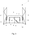
- Figure 1 shows the pendulum suspension device 1 in a situation where a vehicle carrying a sprayer provided with the pendulum suspension device 1 is configured for normal spraying where the center of gravity for the spray boom 2 can swing around the upper pendulum point 7 and only limited (damped) by hydraulic fluid being pushed back and forth between the two pendulum cylinders 9, 10 over the throttle 15.
- the spray booms 2 are folded into a transport position by activating left and right boom cylinders 11, 12 after, or at the same time activating the left and right pendulum cylinders 9, 10 to align the mobile frame 4 with the spray booms 2.
- the angle sensor 13 gives a reading from which it can be determined if or when the mobile frame 4 is aligned with the fixed frame 3.
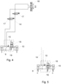
- FIG 4 a simplified hydraulic circuit 14 is shown, where the pendulum cylinders 9, 10 are hydraulically separable connected by cut-off valves 17 capable of opening or closing for hydraulic fluid to the pendulum cylinders 9, 10.
- Fluid direction between the cylinders 9, 10, which cylinders preferably are double action cylinders can be changed by a directional control valve 16 and a throttle 15 placed in a hydraulic interconnection 19 between the pendulum cylinders 9, 10.
- the throttle 15 controls the dampening of the mobile frame 4 in relation to the fixed frame 3.
- a pump pressure control valve 18 is configured for control of the hydraulic fluid between pump (P), tank (T) and the hydraulic circuit 14.
- the directional valve 16 is switched to direct hydraulic fluid into the pendulum cylinders 9, 10 in order to let the cylinders 9, 10 act in opposite directions.
- figure 5 is shown same circuit 14 as in figure 4 , but here the directional valve 16 is switched to direct hydraulic fluid into the pendulum cylinders 9, 10 in order to let the cylinders act in same direction.
- the slant cylinder 6 can be used to displace the center of gravity by increasing or decreasing an angle between the connecting rod 5 which is pivotable connected to the mobile frame 4 in a lower pivot point 8.
- the spray boom 2 can be displaced sideways in relation to the fixed frame 3 and thereby in relation to the carrying vehicle.
- the center When folding the boom, the center must also be locked so that it does not “mis-align" during uneven folding, whereby the center of gravity of the boom is displaced.
- the boom and center must be locked so that the boom remains in transport brackets during road transport.
- Transport brackets can be a substantially vertical pin which is positioned in an opening in such a way that the opening is placed for example in a substantially horizontal flange extending from the fixed frame 3 or a part in fixed connection with the fixed frame 3 on the field sprayer and the pin is placed on a section on the spray boom 2, which section is placed close to and corresponding to the flange, when the spray boom 2 is in folded position.
- the spray boom 2 can be lowered in substantially vertical or upright position by use of a sliding frame (not shown) for moving the mobile frame 4 and/or the fixed frame 3 including the spray boom 2 in a substantially vertical direction.
- This sliding frame can also be used for changing distance between spray boom 2 and the crops to be sprayed.
- the weight of the spray boom 2 keeps the pin engaged with the opening. It can be further secured by locking the fixed 3 and mobile frame 4 in relation to each other so that the spray boom 2 remains in the transport brackets during road transport.
- Locking the frames 3, 4 in relation to each other can be done by closing a valve 17 or by blocking or closing the throttle 15 in such a way that pistons in the pendulum cylinders 9, 10 cannot move or only can move a very short distance.
- the spray boom can on each side of the fixed frame be provided by a number of foldable booms maneuverable or foldable in relation to each other by means of hydraulic cylinders, using wire pull or similar mechanisms.
- variations to the disclosed embodiments can be understood and effected by the skilled person in practicing the claimed disclosure, from a study of the drawings, the disclosure, and the appended claims.
Landscapes
- Life Sciences & Earth Sciences (AREA)
- Engineering & Computer Science (AREA)
- Insects & Arthropods (AREA)
- Pest Control & Pesticides (AREA)
- Wood Science & Technology (AREA)
- Zoology (AREA)
- Environmental Sciences (AREA)
- Catching Or Destruction (AREA)
Abstract
Description
- The present disclosure relates to a pendulum suspension device of a spray boom and a method of aligning a pendulum suspension device of a spray boom. More specifically, the disclosure relates to a pendulum suspension device of a spray boom and a method of aligning a pendulum suspension device of a spray boom as defined in the introductory parts of the independent claims.
- When spraying, the spray boom will pick up movement around a pendulum point placed on a longitudinal axis running in a driving direction of a carrying vehicle, being a tractor or a self-propelled field or crop sprayer. Over the years, spray booms have become longer and longer, some booms having a spraying width of more than 40 meters. Therefore, a need of dampening oscillations of the spray boom is important to for example avoid the boom to hit the ground and to ensure a substantially constant distance between the spray boom and the crops to be sprayed. Some boom types are capable of operating with one side of the spray boom folded, and the other side unfolded. This moves center of gravity (COG.) of the boom towards the unfolded side, creating a tendency, for the whole sprayer, to lean towards that side. In this situation, the free movement around the pendulum point must be disabled, to avoid the boom from rolling to its extremity. To be able to obtain horizontal positioning of the unfolded boom side, correction between the boom and a chassis of the sprayer/vehicle is needed. Further, when the spray boom is going to be folded into a transport position the boom will have to be aligned with the chassis and free movement around the pendulum point will have to be disabled.
- A problem with the solutions of the prior art is that there are many complex systems for enabling such features, but a simple system capable of controlling the above features is not available. There is thus a need for an improved solution to this problem.
- It is an object of the present disclosure to mitigate, alleviate or eliminate one or more of the above-identified deficiencies and disadvantages in the prior art and solve at least the above mentioned problem. According to a first aspect there is provided a pendulum suspension device of a spray boom, comprising: a fixed frame intended to be borne by an agricultural machine, a mobile frame intended to bear one or several spray booms, a pendulum suspension connecting rod connected pivotably in an upper pivot point to the fixed frame, said connecting rod connected pivotally in a lower pivot point to the mobile frame, and at least one actuation cylinder in order to displace a center of gravity for the mobile frame including the spray boom relatively to the fixed frame, the actuation cylinder is interposed between the mobile frame and the connecting rod, the pendulum suspension device further comprising a pair of pendulum cylinders placed on each side of the connecting rod, and connected between the fixed frame and the mobile frame, where the pendulum cylinders are hydraulically connected by a hydraulic interconnection and is configured for dampening movement of the fixed frame in relation to the mobile frame via a throttle placed in the hydraulic interconnection.
- Hereby it is possible in a simple way to regulate the strength of dampening.
- According to some embodiments, the pendulum cylinders are connected hydraulically via a directional control valve for switching between a position of the control valve for movement of the cylinders moving the spray boom and a position for locking of movement of the cylinders.
- Hereby it is possible to use same cylinders to control dampening and to control alignment of the spray boom and the mobile frame in relation to the fixed frame.
- According to some embodiments, the throttle is an adjustable throttle.
- Hereby it is possible to adjust the dampening of movement of the spray boom.
- According to some embodiments, the pendulum cylinders are hydraulically separated from rest of the hydraulic circuit by a cut-off valve.
- Hereby it is possible to create a local hydraulic circuit operable independently of the rest of the hydraulic circuit and it is possible to switch between such a separate operation mode and a mutual operation mode, where the local hydraulic circuit operates together with the rest of the hydraulic circuit. It is also possible by pressing hydraulic fluid into one cylinder and with the other cylinder connected to a tank, to create a controlled movement around the pendulum point of the spray boom and thereby correcting the angle of the boom compared to the chassis.
- According to some embodiments, an angle sensor is provided between the connection bar and the fixed frame.
- Hereby it is possible to determine based on readings of signals from the angle sensor the angle between the connection rod and the fixed frame and thereby it is possible to determine when the spray boom and the mobile frame is level in relation to the fixed frame.
- According to some embodiments, one or more control valves in a hydraulic circuit is controlled by a controller connected to the agricultural machine.
- Hereby it is possible to automatically control the spray boom.
- According to some embodiments, at least one of the control valves in the hydraulic circuit is controlled manually.
- Hereby it is possible for a tractor pilot to control one or more of the parameters manually.
- According to a second aspect there is provided a method of aligning a pendulum suspension device of a spray boom, comprising: a fixed frame intended to be borne by an agricultural machine, a mobile frame intended to bear one or several spray booms, a pendulum suspension connecting rod connected pivotably in an upper pivot point to the fixed frame, said connecting rod connected pivotally in a lower pivot point to the mobile frame, and at least one actuation cylinder in order to displace a center of gravity for the mobile frame including the spray boom relatively to the fixed frame, the actuation cylinder is interposed between the fixed frame and the connecting rod, the pendulum suspension device further comprising a pair of pendulum cylinders placed on each side of the connecting rod, and connected between the fixed frame and the mobile frame, the suspension device controlled by a hydraulic system comprising control valves where the method comprises the steps of: - damping movement of the pendulum cylinders by a throttle valve placed in the hydraulic interconnection between the pendulum cylinders, thereby dampening the movement of the boom, and activating a directional control valve into a position where hydraulic fluid flow from one pendulum cylinder moves the other pendulum cylinder in opposite direction.
- Hereby it is possible to achieve a dampening of spray boom oscillations relative to the sprayer in an efficient and simple way.
- According to some embodiments, the method comprises the steps of: activating hydraulic fluid flow between pendulum cylinders until an angle sensor shows that connection bar is perpendicular to the fixed frame; leveling the mobile frame in relation to the fixed frame into a transport position by activating left and right pendulum cylinders, locking the frames in relation to each other and separating the pendulum cylinders hydraulically by activating the cut-off valve; and folding spray boom into a folded transport position.
- According to some embodiments, the method further comprises the steps of: separating hydraulic fluid flow between pendulum cylinders; pressing hydraulic fluid into one pendulum cylinder and connecting the other pendulum cylinder to a tank to create a controlled movement of the mobile frame around the upper pivot point of the connecting rod.
- Hereby it is possible to achieve a safe folding of the spray boom into a transport position ensuring correct placement of the boom.
- All in all, an improved system is achieved solving the problems of dampening oscillations of the spray boom, aligning the spray boom, for example before folding into transport position, and correcting angle of the spray boom in relation to the surface to be sprayed.
- Effects and features of the second aspect are to a large extent analogous to those described above in connection with the first aspect. Embodiments mentioned in relation to the first aspect are largely compatible with the second aspect.
- The present disclosure will become apparent from the detailed description given below. The detailed description and specific examples disclose preferred embodiments of the disclosure by way of illustration only. Those skilled in the art understand from guidance in the detailed description that changes and modifications may be made within the scope of the disclosure.
- Hence, it is to be understood that the herein disclosed disclosure is not limited to the particular component parts of the device described or steps of the methods described since such device and method may vary. It is also to be understood that the terminology used herein is for purpose of describing particular embodiments only, and is not intended to be limiting. It should be noted that, as used in the specification and the appended claim, the articles "a", "an", "the", and "said" are intended to mean that there are one or more of the elements unless the context explicitly dictates otherwise. Thus, for example, reference to "a unit" or "the unit" may include several devices, and the like. Furthermore, the words "comprising", "including", "containing" and similar wordings does not exclude other elements or steps.
- Terminology -- The term "carrying the sprayer" is to be interpreted as carried by a tractor lift (three-point suspension), a tractor trailer or a self-propelled field sprayer.
- The above objects, as well as additional objects, features and advantages of the present disclosure, will be more fully appreciated by reference to the following illustrative and nonlimiting detailed description of example embodiments of the present disclosure, when taken in conjunction with the accompanying drawings.
-
Figure 1 shows schematically a pendulum suspension device compensating for an uneven field surface; -
Figure 2 shows schematically a pendulum suspension device.in an aligned position; -
Figure 3 shows schematically a pendulum suspension device, where the spray boom is folded into a transport position; -
Figure 4 shows a simplified hydraulic diagram for controlling the pendulum suspension device, when the spray boom is in folding or transport position; -
Figure 5 shows a simplified hydraulic diagram for controlling the pendulum suspension device, when the spray boom is in spraying position with damping enabled; and -
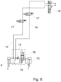
Figure 6 shows a simplified hydraulic diagram for controlling the pendulum suspension device, when the system is in alignment or correction configuration. - The present disclosure will now be described with reference to the accompanying drawings, in which preferred example embodiments of the disclosure are shown. The disclosure may, however, be embodied in other forms and should not be construed as limited to the herein disclosed embodiments. The disclosed embodiments are provided to fully convey the scope of the disclosure to the skilled person.
- The first aspect of this disclosure shows a
pendulum suspension device 1 of aspray boom 2, comprising: a fixedframe 3 intended to be borne by an agricultural machine, amobile frame 4 intended to bear one orseveral spray booms 2, a pendulumsuspension connecting rod 5 connected pivotably in anupper pivot point 7 to thefixed frame 3, the connectingrod 5 connected pivotally in alower pivot point 8 to themobile frame 4, and at least oneactuation cylinder 6 in order to displace a center of gravity for themobile frame 4 including thespray boom 2 relatively to thefixed frame 3, theactuation cylinder 6 is interposed between themobile frame 4 and the connectingrod 5, thependulum suspension device 1 further comprising a pair ofpendulum cylinders rod 5, and connected between thefixed frame 3 and themobile frame 4, where thependulum cylinders hydraulic interconnection 19 and is configured for dampening movement of thefixed frame 3 in relation to themobile frame 4 via athrottle 15 placed in thehydraulic interconnection 19. - In an embodiment, the
pendulum cylinders directional control valve 16 for switching between a position of thecontrol valve 16 for movement of thecylinders spray boom 2 and a position for locking of movement of thecylinders cylinders circuit 14. - The
throttle 15 can be a fixed throttle and in an embodiment, thethrottle 15 is anadjustable throttle 15, whichthrottle 15 can also be mechanically or electronically remotely operated based on external input, for example from GPS signals, demographic charts, topographic charts or the like. Input can also be provided by user of the agricultural vehicle. - Hereby it is possible to let the
adjustable throttle 15 be operated by an operator of the agricultural vehicle or by a controller connected to the agricultural vehicle. - In an aspect, the function of the
adjustable throttle 15 can be integrated into thedirectional control valve 16. As an example, the directional control valve, can then be a proportional valve (not shown). Hereby it is possible to let the proportional valve control connection between thependulum cylinders spray boom 2 by adjusting flow between thependulum cylinders - In an embodiment, the
pendulum cylinders valve 17. - In an embodiment, an
angle sensor 13 is provided between the pendulumsuspension connecting rod 5 and the fixedframe 3. - In an embodiment, one or
more control valves hydraulic circuit 14 is controlled by a controller connected to the agricultural machine. - In an embodiment, at least one of the
control valves hydraulic circuit 14 is controlled manually. - The second aspect of this disclosure shows a method of aligning a pendulum suspension device 1 of a spray boom 2, comprising: a fixed frame 3 intended to be borne by an agricultural machine, a mobile frame 4 intended to bear one or several spray booms 2, a pendulum suspension connecting rod 5 connected pivotably in an upper pivot point 7 to the fixed frame 3, the connecting rod 5 connected pivotally in a lower pivot point 8 to the mobile frame 4, and at least one actuation cylinder 6 in order to displace a center of gravity for the mobile frame 4 including the spray boom 2 relatively to the fixed frame 3, the actuation cylinder 6 is interposed between the mobile frame 4 and the connecting rod 5, the pendulum suspension device 1 further comprising a pair of pendulum cylinders 9, 10 placed on each side of the connecting rod 5, and connected between the fixed frame 3 and the mobile frame 4, the suspension device 1 controlled by a hydraulic system comprising control valves 15, 16, 17, 18 where the method comprises the steps of: - damping movement of the pendulum cylinders 9, 10 by a throttle valve 15 placed in the hydraulic interconnection between the pendulum cylinders 9, 10, thereby dampening the movement of the boom 2, and - activating a directional control valve 16 into a position where hydraulic fluid flow from one pendulum cylinder 9, 10 moves the other pendulum cylinder 9, 10 in opposite direction.
- In an embodiment, the method comprises the steps of: activating hydraulic fluid flow between
pendulum cylinders angle sensor 13 shows thatconnection bar 5 is perpendicular to fixedframe 3; leveling themobile frame 4 in relation to the fixedframe 3 into a transport position by activating left andright pendulum cylinders frames valve 17; and foldingspray boom 2 into a folded transport position. - In an embodiment, the method further comprises the steps of: separating hydraulic fluid flow between
pendulum cylinders pendulum cylinder other pendulum cylinder upper pivot point 7 of the connectingrod 5. - This method is advantageous when one or more elements of the
spray boom 2 on one side is folded, whereby center of gravity will be displaced and a tendency of inclining of thespray boom 2 to the other side will occur. The method makes it possible to compensate for displacement of the center of gravity and to align thespray boom 2 with the field surface. - In the figures, only inner portions of
spray booms 2 are shown. Thespray boom 2 can on each side of the fixedframe 3 be provided by a number offoldable booms 2 maneuverable or foldable in relation to each other by means ofhydraulic cylinders -
Figure 1 shows thependulum suspension device 1 in a situation where a vehicle carrying a sprayer provided with thependulum suspension device 1 is configured for normal spraying where the center of gravity for thespray boom 2 can swing around theupper pendulum point 7 and only limited (damped) by hydraulic fluid being pushed back and forth between the twopendulum cylinders throttle 15. - In
figure 2 , thespray boom 2 and themobile frame 4 is aligned with the fixedframe 3 and the connectingrod 5 is substantially perpendicular to the fixedframe 3, which can be verified by theangle sensor 13. - In
figure 3 , thespray booms 2 are folded into a transport position by activating left andright boom cylinders right pendulum cylinders mobile frame 4 with thespray booms 2. Theangle sensor 13 gives a reading from which it can be determined if or when themobile frame 4 is aligned with the fixedframe 3. - In
figure 4 a simplifiedhydraulic circuit 14 is shown, where thependulum cylinders valves 17 capable of opening or closing for hydraulic fluid to thependulum cylinders cylinders directional control valve 16 and athrottle 15 placed in ahydraulic interconnection 19 between thependulum cylinders throttle 15 controls the dampening of themobile frame 4 in relation to the fixedframe 3. A pumppressure control valve 18 is configured for control of the hydraulic fluid between pump (P), tank (T) and thehydraulic circuit 14. Thedirectional valve 16 is switched to direct hydraulic fluid into thependulum cylinders cylinders - When the
directional valve 16 is switched to direct hydraulic fluid into thependulum cylinders cylinders valves 17 are closed to separate thependulum cylinders pendulum cylinder other pendulum cylinder throttle 15. Shifting thedirectional valve 16 to direct hydraulic fluid into thependulum cylinders cylinders valves 17 closed, the movement of thecylinders - In
figure 5 is shownsame circuit 14 as infigure 4 , but here thedirectional valve 16 is switched to direct hydraulic fluid into thependulum cylinders - In
figure 6 , thecircuit 14 is shown with the cut-offvalves 17 open and the pumppressure control valve 18 switched whereby thependulum cylinders - The
slant cylinder 6 can be used to displace the center of gravity by increasing or decreasing an angle between the connectingrod 5 which is pivotable connected to themobile frame 4 in alower pivot point 8. By use of theslant cylinder 6, thespray boom 2 can be displaced sideways in relation to the fixedframe 3 and thereby in relation to the carrying vehicle. - When folding the boom, the center must also be locked so that it does not "mis-align" during uneven folding, whereby the center of gravity of the boom is displaced. The boom and center must be locked so that the boom remains in transport brackets during road transport.
- Transport brackets (not shown) can be a substantially vertical pin which is positioned in an opening in such a way that the opening is placed for example in a substantially horizontal flange extending from the fixed
frame 3 or a part in fixed connection with the fixedframe 3 on the field sprayer and the pin is placed on a section on thespray boom 2, which section is placed close to and corresponding to the flange, when thespray boom 2 is in folded position. When thespray boom 2 is folded and the pin is placed just above the opening in the flange, thespray boom 2 can be lowered in substantially vertical or upright position by use of a sliding frame (not shown) for moving themobile frame 4 and/or the fixedframe 3 including thespray boom 2 in a substantially vertical direction. This sliding frame can also be used for changing distance betweenspray boom 2 and the crops to be sprayed. - The weight of the
spray boom 2 keeps the pin engaged with the opening. It can be further secured by locking the fixed 3 andmobile frame 4 in relation to each other so that thespray boom 2 remains in the transport brackets during road transport. - Locking the
frames valve 17 or by blocking or closing thethrottle 15 in such a way that pistons in thependulum cylinders - Hereby it is secured that the
spray boom 2 remains in the transport brackets (not shown) during road transport. - The person skilled in the art realizes that the present disclosure is not limited to the preferred embodiments described above. The person skilled in the art further realizes that modifications and variations are possible within the scope of the appended claims. For example, the spray boom can on each side of the fixed frame be provided by a number of foldable booms maneuverable or foldable in relation to each other by means of hydraulic cylinders, using wire pull or similar mechanisms. Additionally, variations to the disclosed embodiments can be understood and effected by the skilled person in practicing the claimed disclosure, from a study of the drawings, the disclosure, and the appended claims.
Claims (10)
- A pendulum suspension device (1) of a spray boom (2), comprising: a fixed frame (3) intended to be borne by an agricultural machine, a mobile frame (4) intended to bear one or several spray booms (2), a pendulum suspension connecting rod (5) connected pivotably in an upper pivot point (7) to the fixed frame (3), said connecting rod (5) connected pivotally in a lower pivot point (8) to the mobile frame (4), and at least one actuation cylinder (6) in order to displace a center of gravity for the mobile frame (4) including the spray boom (2) relatively to said fixed frame (3), said actuation cylinder (6) is interposed between said mobile frame (4) and said connecting rod (5), the pendulum suspension device (1) further comprising a pair of pendulum cylinders (9, 10) placed on each side of the connecting rod (5), and connected between the fixed frame (3) and the mobile frame (4), characterized in that the pendulum cylinders (9, 10) is hydraulically connected by a hydraulic interconnection (19) and is configured for dampening movement of the fixed frame (3) in relation to the mobile frame (4) via a throttle (15) placed in the hydraulic interconnection (19).
- The pendulum suspension device according to claim 1, wherein the pendulum cylinders (9, 10) are connected hydraulically via a directional control valve (16) for switching between a position of the control valve (16) for movement of the cylinders (9, 10) moving the spray boom (2) and a position for locking of movement of the cylinders (9, 10).
- The pendulum suspension device according to claim 1, wherein the throttle (15) is an adjustable throttle (15).
- The pendulum suspension device according to any one or more of the claims 1, 2 or 3, wherein the pendulum cylinders (9, 10) are hydraulically separated from rest of a hydraulic circuit (14) by a cut-off valve (17).
- The pendulum suspension device according to one or more of the claims 1 - 4, wherein an angle sensor (13) is provided between the pendulum suspension connecting rod (5) and the fixed frame (3).
- The pendulum suspension device according to one or more of the claims 1 - 5, wherein one or more control valves (15, 16, 17, 18) in a hydraulic circuit (14) is controlled by a controller connected to the agricultural machine.
- The pendulum suspension device according to one or more of the claims 1 - 5, wherein at least one of the control valves (15, 16, 17, 18) in a hydraulic circuit (14) is controlled manually.
- A method of aligning a pendulum suspension device (1) of a spray boom (2), comprising: a fixed frame (3) intended to be borne by an agricultural machine, a mobile frame (4) intended to bear one or several spray booms (2), a pendulum suspension connecting rod (5) connected pivotably in an upper pivot point (7) to the fixed frame (3), said connecting rod (5) connected pivotally in a lower pivot point (8) to the mobile frame (4), and at least one actuation cylinder (6) in order to displace a center of gravity for the mobile frame (4) including the spray boom (2) relatively to said fixed frame (3), said actuation cylinder (6) is interposed between said mobile frame (4) and said connecting rod (5), the pendulum suspension device (1) further comprising a pair of pendulum cylinders (9, 10) placed on each side of the connecting rod (5), and connected between the fixed frame (3) and the mobile frame (4), said suspension device (1) controlled by a hydraulic system comprising control valves (15, 16, 17, 18) where the method comprises the steps of:- damping of movement of the pendulum cylinders (9, 10) by a throttle valve (15) placed in the hydraulic interconnection (19) between the pendulum cylinders (9, 10), thereby dampening the movement of the boom (2), and- activating a directional control valve (16) into a position where hydraulic fluid flow from one pendulum cylinder (9, 10) moves the other pendulum cylinder (9, 10) in opposite direction.
- The method according to claim 8, further comprising the steps of:- activating hydraulic fluid flow between pendulum cylinders (9, 10) until an angle sensor (13) shows that connection bar (5) is perpendicular to fixed frame (3);- leveling the mobile frame (4) in relation to the fixed frame (3) into a transport position by activating left and right pendulum cylinders (9, 10);- locking the frames (3, 4) in relation to each other and separating the pendulum cylinders hydraulically by activating the cut-off valve (17); and- folding spray boom (2) into a folded transport position;
- The method according to claim 8 further comprising the steps of:- separating hydraulic fluid flow between pendulum cylinders (9, 10);- pressing hydraulic fluid into one pendulum cylinder (9, 10) and connecting the other pendulum cylinder (9, 10) to a tank (T) to create a controlled movement of the mobile frame around the upper pivot point (7) of the connecting rod (5).
Applications Claiming Priority (1)
| Application Number | Priority Date | Filing Date | Title |
|---|---|---|---|
| DKPA202270106 | 2022-03-15 |
Publications (3)
| Publication Number | Publication Date |
|---|---|
| EP4245136A1 true EP4245136A1 (en) | 2023-09-20 |
| EP4245136C0 EP4245136C0 (en) | 2024-11-13 |
| EP4245136B1 EP4245136B1 (en) | 2024-11-13 |
Family
ID=85569632
Family Applications (1)
| Application Number | Title | Priority Date | Filing Date |
|---|---|---|---|
| EP23161137.7A Active EP4245136B1 (en) | 2022-03-15 | 2023-03-10 | A pendulum suspension device of a spray boom and a method of aligning a pendulum suspension device of a spray boom |
Country Status (3)
| Country | Link |
|---|---|
| EP (1) | EP4245136B1 (en) |
| ES (1) | ES2998861T3 (en) |
| PL (1) | PL4245136T3 (en) |
Cited By (1)
| Publication number | Priority date | Publication date | Assignee | Title |
|---|---|---|---|---|
| CN119256957A (en) * | 2024-11-29 | 2025-01-07 | 中国农业大学烟台研究院 | A staggered mobile liquid supply device, tower-type aeroponic system and aeroponic method |
Citations (4)
| Publication number | Priority date | Publication date | Assignee | Title |
|---|---|---|---|---|
| FR2270774A1 (en) * | 1974-05-15 | 1975-12-12 | Berthoud Sa | Suspension for agricultural spray boom - has lifting jack pivotal by shock absorbing side jacks |
| US20140015212A1 (en) * | 2012-07-12 | 2014-01-16 | Exel Industries | Pendulum suspension device of a spray ramp for an agricultural machine |
| EP2932841B1 (en) * | 2014-04-16 | 2017-01-25 | Amazonen-Werke H. Dreyer GmbH & Co. KG | Application vehicle |
| EP3141114B1 (en) * | 2015-09-08 | 2018-08-15 | Herbert Dammann GmbH | Agricultural sprayer and method |
-
2023
- 2023-03-10 ES ES23161137T patent/ES2998861T3/en active Active
- 2023-03-10 PL PL23161137.7T patent/PL4245136T3/en unknown
- 2023-03-10 EP EP23161137.7A patent/EP4245136B1/en active Active
Patent Citations (4)
| Publication number | Priority date | Publication date | Assignee | Title |
|---|---|---|---|---|
| FR2270774A1 (en) * | 1974-05-15 | 1975-12-12 | Berthoud Sa | Suspension for agricultural spray boom - has lifting jack pivotal by shock absorbing side jacks |
| US20140015212A1 (en) * | 2012-07-12 | 2014-01-16 | Exel Industries | Pendulum suspension device of a spray ramp for an agricultural machine |
| EP2932841B1 (en) * | 2014-04-16 | 2017-01-25 | Amazonen-Werke H. Dreyer GmbH & Co. KG | Application vehicle |
| EP3141114B1 (en) * | 2015-09-08 | 2018-08-15 | Herbert Dammann GmbH | Agricultural sprayer and method |
Cited By (2)
| Publication number | Priority date | Publication date | Assignee | Title |
|---|---|---|---|---|
| CN119256957A (en) * | 2024-11-29 | 2025-01-07 | 中国农业大学烟台研究院 | A staggered mobile liquid supply device, tower-type aeroponic system and aeroponic method |
| CN119256957B (en) * | 2024-11-29 | 2026-01-06 | 中国农业大学烟台研究院 | Interleaved mobile liquid supply devices, tower-type aeroponic system and aeroponic method |
Also Published As
| Publication number | Publication date |
|---|---|
| PL4245136T3 (en) | 2025-03-17 |
| ES2998861T3 (en) | 2025-02-21 |
| EP4245136C0 (en) | 2024-11-13 |
| EP4245136B1 (en) | 2024-11-13 |
Similar Documents
| Publication | Publication Date | Title |
|---|---|---|
| US11751556B2 (en) | System and method for actuating a boom assembly of an agricultural sprayer | |
| US7395663B2 (en) | System for and method of locking a roll suspension arrangement for a boom assembly mounted on an agricultural sprayer | |
| US8700273B2 (en) | Implement control system for a machine | |
| US6382326B1 (en) | Implement suspension with accumulator | |
| EP1444894B1 (en) | Roll control system and method for a suspended boom | |
| US20140196996A1 (en) | Boom sprayer and boom vibration control device | |
| CA2570765C (en) | Suspension arrangement for a boom assembly mounted on an agricultural sprayer | |
| DE202007011631U1 (en) | Suspension device for a spreading agricultural implement | |
| US20180110213A1 (en) | Agricultural machine and control method | |
| US20240423190A1 (en) | Sprayer Vehicle Comprising Telescoping Parallel Linkage and Related Methods | |
| US12478056B2 (en) | Agricultural machine having improved suspension | |
| EP4245136B1 (en) | A pendulum suspension device of a spray boom and a method of aligning a pendulum suspension device of a spray boom | |
| AU2020207870B2 (en) | Variable float and variable blade impact | |
| US10420276B2 (en) | Sprayer with automatically controlled laterally and angularly displaceable spray boom assembly | |
| US12434523B2 (en) | System and method for an agricultural vehicle | |
| EP3259986A1 (en) | Boom arrangement and method for adjusting the tilt position of the boom arrangement | |
| US11277967B2 (en) | Harvester transport preparation | |
| KR100502047B1 (en) | Rolling controls of working machine | |
| US20090057045A1 (en) | Hydraulic system to deter lift arm chatter | |
| JP3805200B2 (en) | Work vehicle | |
| JP2023544646A (en) | vehicle suspension system | |
| JPH0361421A (en) | Attitude control device of ground working vehicle | |
| US20250084610A1 (en) | Work vehicle, method of controlling work vehicle, and controller for work vehicle | |
| BR102023023473A2 (en) | SYSTEM AND METHOD FOR AN AGRICULTURAL VEHICLE | |
| JPH0324005Y2 (en) |
Legal Events
| Date | Code | Title | Description |
|---|---|---|---|
| PUAI | Public reference made under article 153(3) epc to a published international application that has entered the european phase |
Free format text: ORIGINAL CODE: 0009012 |
|
| STAA | Information on the status of an ep patent application or granted ep patent |
Free format text: STATUS: THE APPLICATION HAS BEEN PUBLISHED |
|
| AK | Designated contracting states |
Kind code of ref document: A1 Designated state(s): AL AT BE BG CH CY CZ DE DK EE ES FI FR GB GR HR HU IE IS IT LI LT LU LV MC ME MK MT NL NO PL PT RO RS SE SI SK SM TR |
|
| STAA | Information on the status of an ep patent application or granted ep patent |
Free format text: STATUS: REQUEST FOR EXAMINATION WAS MADE |
|
| 17P | Request for examination filed |
Effective date: 20240209 |
|
| RBV | Designated contracting states (corrected) |
Designated state(s): AL AT BE BG CH CY CZ DE DK EE ES FI FR GB GR HR HU IE IS IT LI LT LU LV MC ME MK MT NL NO PL PT RO RS SE SI SK SM TR |
|
| GRAP | Despatch of communication of intention to grant a patent |
Free format text: ORIGINAL CODE: EPIDOSNIGR1 |
|
| STAA | Information on the status of an ep patent application or granted ep patent |
Free format text: STATUS: GRANT OF PATENT IS INTENDED |
|
| RIC1 | Information provided on ipc code assigned before grant |
Ipc: A01M 9/00 20060101ALI20240529BHEP Ipc: A01M 7/00 20060101AFI20240529BHEP |
|
| INTG | Intention to grant announced |
Effective date: 20240619 |
|
| GRAS | Grant fee paid |
Free format text: ORIGINAL CODE: EPIDOSNIGR3 |
|
| GRAA | (expected) grant |
Free format text: ORIGINAL CODE: 0009210 |
|
| STAA | Information on the status of an ep patent application or granted ep patent |
Free format text: STATUS: THE PATENT HAS BEEN GRANTED |
|
| AK | Designated contracting states |
Kind code of ref document: B1 Designated state(s): AL AT BE BG CH CY CZ DE DK EE ES FI FR GB GR HR HU IE IS IT LI LT LU LV MC ME MK MT NL NO PL PT RO RS SE SI SK SM TR |
|
| REG | Reference to a national code |
Ref country code: GB Ref legal event code: FG4D |
|
| REG | Reference to a national code |
Ref country code: CH Ref legal event code: EP |
|
| REG | Reference to a national code |
Ref country code: DE Ref legal event code: R096 Ref document number: 602023000977 Country of ref document: DE |
|
| REG | Reference to a national code |
Ref country code: IE Ref legal event code: FG4D |
|
| U01 | Request for unitary effect filed |
Effective date: 20241206 |
|
| U07 | Unitary effect registered |
Designated state(s): AT BE BG DE DK EE FI FR IT LT LU LV MT NL PT RO SE SI Effective date: 20241219 |
|
| REG | Reference to a national code |
Ref country code: ES Ref legal event code: FG2A Ref document number: 2998861 Country of ref document: ES Kind code of ref document: T3 Effective date: 20250221 |
|
| U20 | Renewal fee for the european patent with unitary effect paid |
Year of fee payment: 3 Effective date: 20250225 |
|
| PG25 | Lapsed in a contracting state [announced via postgrant information from national office to epo] |
Ref country code: HR Free format text: LAPSE BECAUSE OF FAILURE TO SUBMIT A TRANSLATION OF THE DESCRIPTION OR TO PAY THE FEE WITHIN THE PRESCRIBED TIME-LIMIT Effective date: 20241113 Ref country code: IS Free format text: LAPSE BECAUSE OF FAILURE TO SUBMIT A TRANSLATION OF THE DESCRIPTION OR TO PAY THE FEE WITHIN THE PRESCRIBED TIME-LIMIT Effective date: 20250313 |
|
| PG25 | Lapsed in a contracting state [announced via postgrant information from national office to epo] |
Ref country code: NO Free format text: LAPSE BECAUSE OF FAILURE TO SUBMIT A TRANSLATION OF THE DESCRIPTION OR TO PAY THE FEE WITHIN THE PRESCRIBED TIME-LIMIT Effective date: 20250213 |
|
| PG25 | Lapsed in a contracting state [announced via postgrant information from national office to epo] |
Ref country code: GR Free format text: LAPSE BECAUSE OF FAILURE TO SUBMIT A TRANSLATION OF THE DESCRIPTION OR TO PAY THE FEE WITHIN THE PRESCRIBED TIME-LIMIT Effective date: 20250214 |
|
| PG25 | Lapsed in a contracting state [announced via postgrant information from national office to epo] |
Ref country code: RS Free format text: LAPSE BECAUSE OF FAILURE TO SUBMIT A TRANSLATION OF THE DESCRIPTION OR TO PAY THE FEE WITHIN THE PRESCRIBED TIME-LIMIT Effective date: 20250213 |
|
| PG25 | Lapsed in a contracting state [announced via postgrant information from national office to epo] |
Ref country code: SM Free format text: LAPSE BECAUSE OF FAILURE TO SUBMIT A TRANSLATION OF THE DESCRIPTION OR TO PAY THE FEE WITHIN THE PRESCRIBED TIME-LIMIT Effective date: 20241113 |
|
| PG25 | Lapsed in a contracting state [announced via postgrant information from national office to epo] |
Ref country code: SK Free format text: LAPSE BECAUSE OF FAILURE TO SUBMIT A TRANSLATION OF THE DESCRIPTION OR TO PAY THE FEE WITHIN THE PRESCRIBED TIME-LIMIT Effective date: 20241113 |
|
| PLBE | No opposition filed within time limit |
Free format text: ORIGINAL CODE: 0009261 |
|
| STAA | Information on the status of an ep patent application or granted ep patent |
Free format text: STATUS: NO OPPOSITION FILED WITHIN TIME LIMIT |
|
| PG25 | Lapsed in a contracting state [announced via postgrant information from national office to epo] |
Ref country code: MC Free format text: LAPSE BECAUSE OF FAILURE TO SUBMIT A TRANSLATION OF THE DESCRIPTION OR TO PAY THE FEE WITHIN THE PRESCRIBED TIME-LIMIT Effective date: 20241113 |
|
| 26N | No opposition filed |
Effective date: 20250814 |
|
| PG25 | Lapsed in a contracting state [announced via postgrant information from national office to epo] |
Ref country code: IE Free format text: LAPSE BECAUSE OF NON-PAYMENT OF DUE FEES Effective date: 20250310 |
|
| U20 | Renewal fee for the european patent with unitary effect paid |
Year of fee payment: 4 Effective date: 20260226 |
|
| PGFP | Annual fee paid to national office [announced via postgrant information from national office to epo] |
Ref country code: CZ Payment date: 20260223 Year of fee payment: 4 |
|
| PGFP | Annual fee paid to national office [announced via postgrant information from national office to epo] |
Ref country code: PL Payment date: 20260225 Year of fee payment: 4 |
|
| PG25 | Lapsed in a contracting state [announced via postgrant information from national office to epo] |
Ref country code: CY Free format text: LAPSE BECAUSE OF FAILURE TO SUBMIT A TRANSLATION OF THE DESCRIPTION OR TO PAY THE FEE WITHIN THE PRESCRIBED TIME-LIMIT Effective date: 20241113 |
|
| PG25 | Lapsed in a contracting state [announced via postgrant information from national office to epo] |
Ref country code: TR Free format text: LAPSE BECAUSE OF FAILURE TO SUBMIT A TRANSLATION OF THE DESCRIPTION OR TO PAY THE FEE WITHIN THE PRESCRIBED TIME-LIMIT Effective date: 20241113 |
|
| PGFP | Annual fee paid to national office [announced via postgrant information from national office to epo] |
Ref country code: ES Payment date: 20260410 Year of fee payment: 4 |