EP4244637B1 - Arc fault detection by accumulation of machine learning classifications in a circuit breaker - Google Patents
Arc fault detection by accumulation of machine learning classifications in a circuit breaker Download PDFInfo
- Publication number
- EP4244637B1 EP4244637B1 EP22702383.5A EP22702383A EP4244637B1 EP 4244637 B1 EP4244637 B1 EP 4244637B1 EP 22702383 A EP22702383 A EP 22702383A EP 4244637 B1 EP4244637 B1 EP 4244637B1
- Authority
- EP
- European Patent Office
- Prior art keywords
- circuit breaker
- machine learning
- signal
- microcontroller
- arc
- Prior art date
- Legal status (The legal status is an assumption and is not a legal conclusion. Google has not performed a legal analysis and makes no representation as to the accuracy of the status listed.)
- Active
Links
Images





Classifications
-
- G—PHYSICS
- G01—MEASURING; TESTING
- G01R—MEASURING ELECTRIC VARIABLES; MEASURING MAGNETIC VARIABLES
- G01R31/00—Arrangements for testing electric properties; Arrangements for locating electric faults; Arrangements for electrical testing characterised by what is being tested not provided for elsewhere
- G01R31/12—Testing dielectric strength or breakdown voltage ; Testing or monitoring effectiveness or level of insulation, e.g. of a cable or of an apparatus, for example using partial discharge measurements; Electrostatic testing
- G01R31/1227—Testing dielectric strength or breakdown voltage ; Testing or monitoring effectiveness or level of insulation, e.g. of a cable or of an apparatus, for example using partial discharge measurements; Electrostatic testing of components, parts or materials
- G01R31/1263—Testing dielectric strength or breakdown voltage ; Testing or monitoring effectiveness or level of insulation, e.g. of a cable or of an apparatus, for example using partial discharge measurements; Electrostatic testing of components, parts or materials of solid or fluid materials, e.g. insulation films, bulk material; of semiconductors or LV electronic components or parts; of cable, line or wire insulation
- G01R31/1272—Testing dielectric strength or breakdown voltage ; Testing or monitoring effectiveness or level of insulation, e.g. of a cable or of an apparatus, for example using partial discharge measurements; Electrostatic testing of components, parts or materials of solid or fluid materials, e.g. insulation films, bulk material; of semiconductors or LV electronic components or parts; of cable, line or wire insulation of cable, line or wire insulation, e.g. using partial discharge measurements
-
- H—ELECTRICITY
- H01—ELECTRIC ELEMENTS
- H01H—ELECTRIC SWITCHES; RELAYS; SELECTORS; EMERGENCY PROTECTIVE DEVICES
- H01H83/00—Protective switches, e.g. circuit-breaking switches, or protective relays operated by abnormal electrical conditions otherwise than solely by excess current
- H01H83/20—Protective switches, e.g. circuit-breaking switches, or protective relays operated by abnormal electrical conditions otherwise than solely by excess current operated by excess current as well as by some other abnormal electrical condition
-
- H—ELECTRICITY
- H02—GENERATION; CONVERSION OR DISTRIBUTION OF ELECTRIC POWER
- H02H—EMERGENCY PROTECTIVE CIRCUIT ARRANGEMENTS
- H02H1/00—Details of emergency protective circuit arrangements
- H02H1/0007—Details of emergency protective circuit arrangements concerning the detecting means
- H02H1/0015—Using arc detectors
-
- H—ELECTRICITY
- H02—GENERATION; CONVERSION OR DISTRIBUTION OF ELECTRIC POWER
- H02H—EMERGENCY PROTECTIVE CIRCUIT ARRANGEMENTS
- H02H1/00—Details of emergency protective circuit arrangements
- H02H1/0092—Details of emergency protective circuit arrangements concerning the data processing means, e.g. expert systems, neural networks
-
- H—ELECTRICITY
- H04—ELECTRIC COMMUNICATION TECHNIQUE
- H04B—TRANSMISSION
- H04B17/00—Monitoring; Testing
- H04B17/30—Monitoring; Testing of propagation channels
- H04B17/309—Measuring or estimating channel quality parameters
- H04B17/318—Received signal strength
-
- H—ELECTRICITY
- H01—ELECTRIC ELEMENTS
- H01H—ELECTRIC SWITCHES; RELAYS; SELECTORS; EMERGENCY PROTECTIVE DEVICES
- H01H83/00—Protective switches, e.g. circuit-breaking switches, or protective relays operated by abnormal electrical conditions otherwise than solely by excess current
- H01H83/20—Protective switches, e.g. circuit-breaking switches, or protective relays operated by abnormal electrical conditions otherwise than solely by excess current operated by excess current as well as by some other abnormal electrical condition
- H01H2083/201—Protective switches, e.g. circuit-breaking switches, or protective relays operated by abnormal electrical conditions otherwise than solely by excess current operated by excess current as well as by some other abnormal electrical condition the other abnormal electrical condition being an arc fault
Definitions
- aspects of the present invention generally relate to arc fault detection by accumulation of machine learning classifications in a circuit breaker.
- AFCIs rely on internal electronics to analyze various analog signals (current and voltage) that pass through the circuit breaker to determine if an arc fault exists downstream of it.
- Prior art investigations tend to ignore utilizing the inferences from a machine learning classifier (neural network or other) to accumulate positive inferences (and decrement negative inferences) into a final decision to trip the circuit breaker in a specific amount of time to meet the safety limits detailed in various industry standards (e.g., UL1699 or other equivalents).
- aspects of the present invention relate to thermal management in a circuit breaker.
- the objective of the described invention is to focus on the types of signals and measurements to be made and analyzed, including investigations into the use of various machine learning mechanisms.
- a final step of utilizing the inferences from the machine learning classifier is designed to accumulate positive inferences (and decrement negative inferences) into making a final decision to trip the breaker in a specific amount of time to meet the safety limits detailed in various industry standards (e.g., UL1699 or other equivalents).
- a circuit breaker comprises a microcontroller including a processor and a memory.
- the circuit breaker further comprises computer-readable software code stored in the memory which, when executed by the processor, causes the microcontroller to: sample analog signals representing one or more of the following: a Received Signal Strength Indicator (RSSI) signal, a voltage signal, and a current signal, perform multiple pre-processing steps on the analog signals to derive a data set of measurements and features over a period of time, and input the data set into a machine learning classifier that resides in the microcontroller such that an output of the machine learning classifier is a value between 0 and 1 which represents a percent chance that the data set is from an electrical arc.
- RSSI Received Signal Strength Indicator
- an accumulator value is either incremented or decremented in proportion to an amount of the current passing through the circuit breaker and if the accumulator value passes an upper threshold level, the microcontroller sends a signal output to a trip circuit which then opens the circuit breaker.
- a method of arc fault detection by accumulation of machine learning classifications comprises providing a microcontroller including a processor and a memory.
- the method further comprises providing computer-readable software code stored in the memory which, when executed by the processor, causes the microcontroller to: sample analog signals representing one or more of the following: a Received Signal Strength Indicator (RSSI) signal, a voltage signal, and a current signal, perform multiple pre-processing steps on the analog signals to derive a data set of measurements and features over a period of time, and input the data set into a machine learning classifier that resides in the microcontroller such that an output of the machine learning classifier is a value between 0 and 1 which represents a percent chance that the data set is from an electrical arc.
- RSSI Received Signal Strength Indicator
- an accumulator value is either incremented or decremented in proportion to an amount of the current passing through the circuit breaker and if the accumulator value passes an upper threshold level, the microcontroller sends a signal output to a trip circuit which then opens the circuit breaker.
- a circuit breaker with software code provides classifications per half-cycle through accumulation of an inference output from a machine learning classifier for providing a final decision to trip the circuit breaker in a specific amount of time to meet the safety limits detailed in various industry standards.
- Embodiments of the present invention are not limited to use in the described devices or methods.
- FIGs. 1-13 These and other embodiments of the circuit breaker according to the present disclosure are described below with reference to FIGs. 1-13 herein.
- Like reference numerals used in the drawings identify similar or identical elements throughout the several views. The drawings are not necessarily drawn to scale.
- FIG. 1 represents a circuit breaker 105 in accordance with an exemplary embodiment of the present invention.
- the circuit breaker 105 is an arc fault circuit interrupter (AFCI) with the capabilities of detecting and tripping on arc faults without causing unwanted tripping on various residential products (i.e. lighting, microwaves, vacuum cleaners, power tools, etc.).
- An arc fault circuit interrupter (AFCI) is an advanced circuit breaker that, as a way to reduce electrical fire threats, breaks the circuit when it detects a dangerous electric arc in the circuit that it protects.
- AFCIs rely on internal electronics to analyze various analog signals (current and voltage) that pass through the circuit breaker 105 to determine if an arc fault exists downstream of it.
- FIG. 2 it illustrates an exploded view of the circuit breaker 105 of FIG. 1 in accordance with an exemplary embodiment of the present invention.
- This is an isometric view of an AFCI.
- the right-side cutaway shows a printed circuit board assembly (PCBA) 205, which contains a microcontroller 207 and accompanying circuitry.
- the microcontroller 207 includes a logic for detecting and tripping the circuit breaker 105 for overcurrent, differential, and arc faults.
- FIG. 3 it illustrates a block diagram of a circuit breaker 305 in accordance with an exemplary embodiment of the present invention.
- the circuit breaker 305 comprises a microcontroller 307 including a processor 310(1) and a memory 310(2).
- the circuit breaker 305 further comprises computer-readable software code 312 stored in the memory 310(2) which, when executed by the processor 310(1), causes the microcontroller 307 to sample analog signals 315 representing one or more of the following: a Received Signal Strength Indicator (RSSI) signal 315(1), a voltage signal 315(2), and a current signal 315(3).
- RSSI Received Signal Strength Indicator
- an accumulator value 335 is either incremented or decremented in proportion to an amount of the current 337 passing through the circuit breaker 305 and if the accumulator value 335 passes an upper threshold level 340, the microcontroller 307 sends a signal output 342 to a trip circuit 345 which then opens the circuit breaker 305.
- the Received Signal Strength Indicator (RSSI) signal 315(1) and the current signal 315(3) come from an analog front-end ASIC circuitry 350.
- the analog front-end ASIC circuitry 350 acts as an interface between a radio frequency (RF) coupler, shunt resistance sensors and the microcontroller 307.
- the microcontroller 307 includes a logic 352 for detecting and tripping the circuit breaker 305 for overcurrent, differential, and arc faults.
- the computer-readable software code 312 is to digitally convert the Received Signal Strength Indicator (RSSI) signal 315(1), the voltage signal 315(2), and the current signal 315(3). Then extract half-cycle features 355 from the Received Signal Strength Indicator (RSSI) signal 315(1), the voltage signal 315(2), and the current signal 315(3). Next, run half-cycle features 355 set through the machine learning classifier 325 and analyze an output of the machine learning classifier 325 to determine if half-cycle was an arc or not. If there is an arc inference, the computer-readable software code 312 is to increment the accumulator value 335 proportional to an amount of the current.
- RSSI Received Signal Strength Indicator
- the computer-readable software code 312 is to digitally convert the Received Signal Strength Indicator (RSSI) signal 315(1), the voltage signal 315(2), and the current signal 315(3).
- run half-cycle features 355 set through the machine learning classifier 325 and analyze an output of the machine learning
- the computer-readable software code 312 is to check whether the accumulator value 335 exceeds a max accumulator threshold and if so trip the circuit breaker 305. If there is no arc inference, the computer-readable software code 312 is to decrement the accumulator value 335 proportional to an amount of the current.
- an analog signal representing the RSSI level present on the residential wiring downstream of an AFCI is measured and analyzed in real-time to produce a set of features at the end of each half-cycle of the power line frequency (i.e. every 8.33ms for the 60Hz frequency in the U.S.). These features are then fed into the machine learning classifier 325 (in our case a neural network, but other classifier types could also be used) that has been previously trained to recognize arc faults.
- the output of the classifier 325 is a number between 0 and 1 representing the percent confidence that the last half-cycle was an electrical arc.
- an accumulator a separate stored value in proportion to the amount of current present during this half-cycle event (e.g., a peak value of the current during this half-cycle, but other common measurements such as RMS or average could also be used). If the classifier 325 value is less than a threshold, the computer-readable software code 312 in turn decrements the accumulator by the same amount, in proportion to the amount of current present in that half-cycle. If the accumulator passes a maximum threshold an arc fault will have been deemed to be present, and the AFCI will trip to open the circuit.
- This incrementing and decrementing of the accumulator works to average out multiple inferences over time while weighting for the amount of current present, to ensure that the AFCI will trip within safe limits while also giving a maximum amount of time for discrimination of residential loads to minimize unwanted tripping.
- the inference itself could also be used in further weighting schemes, such as one where inferences at the min/max of 0 or 1 would result in full changes to the accumulator (still also weighted by the amount of current), with the shift being scaled down to 0 the closer the inference is to 0.5 (where the classifier 325 isn't sure if it is an arc or not).
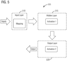
- the NN 505 comprises an input layer 5 10, a hidden layer 515 and an output layer 520.
- Training data includes split - 80% training, 0% validation, 20% testing, samples of arcing, and samples of nuisance and randomized distribution of samples in split.
- the training method may update the weight and bias values according to optimization and minimizes a combination of squared errors and weights to determine the correct combination so as to produce a network which generalizes well.
- Training method parameters left set to 'default' (Note: Does not need validation data set).
- the performance function is Mean-squared Error. This determines the overall performance of the network by comparing the target vs. desired output.
- the hidden layer 615 is located between the input and output of the algorithm, in which the function applies weights to the inputs and directs them through an activation function as the output.
- the hidden layers perform nonlinear transformations of the inputs entered into the neural network.
- FIG. 7 it illustrates a machine learning approach 700 for arc detection in accordance with an exemplary embodiment of the present invention.
- analog signals including current, RSSI, and voltage are received.
- digital conversion of the analog signals is performed.
- Pre-processing of data is done into set of measurements at a step 715.
- Arc detection is done by Neural Network computation instead of data comparison to multiple thresholds at a step 720.
- accumulation of multiple arc detections over time goes into a decision to trip an AFCI.
- FIG. 9 it illustrates neural network features in accordance with an exemplary embodiment of the present invention.
- the features for a neural network include specific data points 905 during an event, slope of a waveform 920 at the start and end and a half-cycle duration 915.
- FIG. 11 illustrates a flow diagram for the software code 312 running in the microcontroller 207, 307, 407 in accordance with an exemplary embodiment of the present invention.
- the software code 312 provides classifications per half-cycle through accumulation of an inference output from a machine learning classifier.
- an accumulator value is incremented proportional to an amount of current.
- a check is made to determine if the accumulator value exceeded a max accumulation threshold. If the determination in the step 1140 is "yes” then at a step 1145 an AFCI device is tripped.
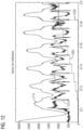
- FIG. 12 illustrates an example of accumulator incrementing as a neural network (NN) algorithm detects electrical arc events using current and RSSI signals at each half-cycle in accordance with an exemplary embodiment of the present invention.
- NN neural network
- the method 1300 comprises a step 1305 of providing a microcontroller including a processor and a memory.
- the method 1300 further comprises a step 1310 of providing computer-readable software code stored in the memory which, when executed by the processor, causes the microcontroller to: sample analog signals representing one or more of the following: a Received Signal Strength Indicator (RSSI) signal, a voltage signal, and a current signal, perform multiple pre-processing steps on the analog signals to derive a data set of measurements and features for every half-cycle of current passing through the circuit breaker, and input the data set into a machine learning classifier that resides in the microcontroller such that an output of the machine learning classifier is a value between 0 and 1 which represents a percent chance that the data set is from an electrical arc.
- RSSI Received Signal Strength Indicator
- an accumulator value is either incremented or decremented in proportion to an amount of the current passing through the circuit breaker and if the accumulator value passes an upper threshold level, the microcontroller sends a signal output to a trip circuit which then opens the circuit breaker.
- the techniques described herein can be particularly useful for arc detection in an AFCI circuit breaker. While particular embodiments are described in terms of specific configuration of an AFCI, the techniques described herein are not limited to such a limited configuration but can also be used with other configurations and types of circuit breakers.
Landscapes
- Engineering & Computer Science (AREA)
- Physics & Mathematics (AREA)
- Quality & Reliability (AREA)
- Electromagnetism (AREA)
- Computer Networks & Wireless Communication (AREA)
- Signal Processing (AREA)
- Artificial Intelligence (AREA)
- Evolutionary Computation (AREA)
- General Physics & Mathematics (AREA)
- Emergency Protection Circuit Devices (AREA)
- Breakers (AREA)
Description
- Aspects of the present invention generally relate to arc fault detection by accumulation of machine learning classifications in a circuit breaker.
- Circuit breakers are essential for electrical safeties. They feed current to loads that are connected to them and interrupt the circuit once a circuit fault such as an overload, a short circuit, a ground fault and an arc fault is detected. We need the capabilities of an arc fault circuit interrupter (AFCI) in detecting and tripping on arc faults without causing unwanted tripping on various residential products (i.e. lighting, microwaves, vacuum cleaners, power tools, etc.). An arc fault circuit interrupter (AFCI) is an advanced circuit breaker that, as a way to reduce electrical fire threats, breaks the circuit when it detects a dangerous electric arc in the circuit that it protects.
- AFCIs rely on internal electronics to analyze various analog signals (current and voltage) that pass through the circuit breaker to determine if an arc fault exists downstream of it. Prior art investigations tend to ignore utilizing the inferences from a machine learning classifier (neural network or other) to accumulate positive inferences (and decrement negative inferences) into a final decision to trip the circuit breaker in a specific amount of time to meet the safety limits detailed in various industry standards (e.g., UL1699 or other equivalents). Prior art AFCI's are known from
US2002/118022 ,US2008/030199 , nad from the IEEE papers KEYHANI: "A high impedance fault detector using a neural network and subband decomposition", SIGNAL PROCESSING AND ITS APPICATIONS, SIXTH INTERNATIONAL, SYMPOSIUM 2001, pages 458-461, XP010557086; and VU: "Multi criteria series arc fault detection based on supervised feature selection", INTERNATIONAL JOURNAL OF ELECTRICAL POWER & ENERGY SYSTEMS, vol. 113, 18 May 2019, pages 23-34, XP085724375, each describing AFCI's involving sampling and preprocessing analog signals, neural network classifiers, and counters/accumulators, but none providing a temporal data set that is fed to a machine learning classifier that indicates a probability that the set comprises an arcing event, followed by incrementing or decrementing an accumulator based on the probability and in proportion to the current flowing in the breaker; and signalling the breaker to trip if the accumulator value exceeds a threshold. - Therefore, there is a need for a better arc fault detection in a circuit breaker.
- Briefly described, aspects of the present invention relate to thermal management in a circuit breaker. The objective of the described invention is to focus on the types of signals and measurements to be made and analyzed, including investigations into the use of various machine learning mechanisms. A final step of utilizing the inferences from the machine learning classifier (neural network or other) is designed to accumulate positive inferences (and decrement negative inferences) into making a final decision to trip the breaker in a specific amount of time to meet the safety limits detailed in various industry standards (e.g., UL1699 or other equivalents).
- In accordance with one illustrative embodiment of the present invention, a circuit breaker comprises a microcontroller including a processor and a memory. The circuit breaker further comprises computer-readable software code stored in the memory which, when executed by the processor, causes the microcontroller to: sample analog signals representing one or more of the following: a Received Signal Strength Indicator (RSSI) signal, a voltage signal, and a current signal, perform multiple pre-processing steps on the analog signals to derive a data set of measurements and features over a period of time, and input the data set into a machine learning classifier that resides in the microcontroller such that an output of the machine learning classifier is a value between 0 and 1 which represents a percent chance that the data set is from an electrical arc. Based on the value of the percent chance an accumulator value is either incremented or decremented in proportion to an amount of the current passing through the circuit breaker and if the accumulator value passes an upper threshold level, the microcontroller sends a signal output to a trip circuit which then opens the circuit breaker.
- In accordance with one illustrative embodiment of the present invention, a method of arc fault detection by accumulation of machine learning classifications is provided. The method comprises providing a microcontroller including a processor and a memory. The method further comprises providing computer-readable software code stored in the memory which, when executed by the processor, causes the microcontroller to: sample analog signals representing one or more of the following: a Received Signal Strength Indicator (RSSI) signal, a voltage signal, and a current signal, perform multiple pre-processing steps on the analog signals to derive a data set of measurements and features over a period of time, and input the data set into a machine learning classifier that resides in the microcontroller such that an output of the machine learning classifier is a value between 0 and 1 which represents a percent chance that the data set is from an electrical arc. Based on the value of the percent chance an accumulator value is either incremented or decremented in proportion to an amount of the current passing through the circuit breaker and if the accumulator value passes an upper threshold level, the microcontroller sends a signal output to a trip circuit which then opens the circuit breaker.
-
-
FIG. 1 illustrates a circuit breaker in accordance with an exemplary embodiment of the present invention. -
FIG. 2 illustrates an exploded view of the circuit breaker ofFIG. 1 in accordance with an exemplary embodiment of the present invention. -
FIG. 3 illustrates a block diagram of a circuit breaker in accordance with an exemplary embodiment of the present invention. -
FIG. 4 illustrates a circuit block diagram of a circuit breaker in accordance with an exemplary embodiment of the present invention. -
FIG. 5 illustrates description of a neural network in accordance with an exemplary embodiment of the present invention. -
FIG. 6 illustrates a neural network model, neural network training, a hidden layer in accordance with an exemplary embodiment of the present invention. -
FIG. 7 illustrates a machine learning approach for arc detection in accordance with an exemplary embodiment of the present invention. -
FIG. 8 illustrates a machine learning classifier in accordance with an exemplary embodiment of the present invention. -
FIG. 9 illustrates neural network features in accordance with an exemplary embodiment of the present invention. -
FIG. 10 illustrates neural network summary in accordance with an exemplary embodiment of the present invention. -
FIG. 11 illustrates a flow diagram for the software code running in the microcontroller in accordance with an exemplary embodiment of the present invention. -
FIG. 12 illustrates an example of accumulator incrementing as a neural network (NN) algorithm detects electrical arc events using current and RSSI signals at each half-cycle in accordance with an exemplary embodiment of the present invention. -
FIG. 13 illustrates a schematic view of a flow chart of a method of arc fault detection by accumulation of machine learning classifications in a circuit breaker in accordance with an exemplary embodiment of the present invention. - To facilitate an understanding of embodiments, principles, and features of the present invention, they are explained hereinafter with reference to implementation in illustrative embodiments. In particular, they are described in the context of utilization of a machine learning classifier with a meaningful accumulation of inferences over time to create a fully working arc detection and interruption algorithm in an AFCI. A circuit breaker with software code provides classifications per half-cycle through accumulation of an inference output from a machine learning classifier for providing a final decision to trip the circuit breaker in a specific amount of time to meet the safety limits detailed in various industry standards. Embodiments of the present invention, however, are not limited to use in the described devices or methods.
- The components and materials described hereinafter as making up the various embodiments are intended to be illustrative and not restrictive. Many suitable components and materials that would perform the same or a similar function as the materials described herein are intended to be embraced within the scope of embodiments of the present invention.
- These and other embodiments of the circuit breaker according to the present disclosure are described below with reference to
FIGs. 1-13 herein. Like reference numerals used in the drawings identify similar or identical elements throughout the several views. The drawings are not necessarily drawn to scale. - Consistent with one embodiment of the present invention,
FIG. 1 represents acircuit breaker 105 in accordance with an exemplary embodiment of the present invention. Thecircuit breaker 105 is an arc fault circuit interrupter (AFCI) with the capabilities of detecting and tripping on arc faults without causing unwanted tripping on various residential products (i.e. lighting, microwaves, vacuum cleaners, power tools, etc.). An arc fault circuit interrupter (AFCI) is an advanced circuit breaker that, as a way to reduce electrical fire threats, breaks the circuit when it detects a dangerous electric arc in the circuit that it protects. AFCIs rely on internal electronics to analyze various analog signals (current and voltage) that pass through thecircuit breaker 105 to determine if an arc fault exists downstream of it. - Referring to
FIG. 2 , it illustrates an exploded view of thecircuit breaker 105 ofFIG. 1 in accordance with an exemplary embodiment of the present invention. This is an isometric view of an AFCI. The right-side cutaway shows a printed circuit board assembly (PCBA) 205, which contains amicrocontroller 207 and accompanying circuitry. Themicrocontroller 207 includes a logic for detecting and tripping thecircuit breaker 105 for overcurrent, differential, and arc faults. - Turning now to
FIG. 3 , it illustrates a block diagram of acircuit breaker 305 in accordance with an exemplary embodiment of the present invention. Thecircuit breaker 305 comprises amicrocontroller 307 including a processor 310(1) and a memory 310(2). Thecircuit breaker 305 further comprises computer-readable software code 312 stored in the memory 310(2) which, when executed by the processor 310(1), causes themicrocontroller 307 to sampleanalog signals 315 representing one or more of the following: a Received Signal Strength Indicator (RSSI) signal 315(1), a voltage signal 315(2), and a current signal 315(3). Execution of the computer-readable software code 312 further causes themicrocontroller 307 to perform multiplepre-processing steps 317 on theanalog signals 315 to derive a data set 320 of measurements and features over a period of time, e.g., for every half-cycle 322 of current passing through thecircuit breaker 305. Execution of the computer-readable software code 312 further causes themicrocontroller 307 to input the data set 320 into amachine learning classifier 325 that resides in themicrocontroller 307 such that anoutput 327 of themachine learning classifier 325 is a value between 0 and 1 which represents apercent chance 330 that the data set 320 is from anelectrical arc 332. Based on the value of thepercent chance 330 anaccumulator value 335 is either incremented or decremented in proportion to an amount of the current 337 passing through thecircuit breaker 305 and if theaccumulator value 335 passes anupper threshold level 340, themicrocontroller 307 sends asignal output 342 to atrip circuit 345 which then opens thecircuit breaker 305. - The
machine learning classifier 325 may be a trained neural network. Theanalog signals 315 data is analyzed and classified from specific pre-processing features at each half-cycle by themachine learning classifier 325. - The Received Signal Strength Indicator (RSSI) signal 315(1) and the current signal 315(3) come from an analog front-
end ASIC circuitry 350. The analog front-end ASIC circuitry 350 acts as an interface between a radio frequency (RF) coupler, shunt resistance sensors and themicrocontroller 307. Themicrocontroller 307 includes alogic 352 for detecting and tripping thecircuit breaker 305 for overcurrent, differential, and arc faults. - In operation, the computer-
readable software code 312 is to digitally convert the Received Signal Strength Indicator (RSSI) signal 315(1), the voltage signal 315(2), and the current signal 315(3). Then extract half-cycle features 355 from the Received Signal Strength Indicator (RSSI) signal 315(1), the voltage signal 315(2), and the current signal 315(3). Next, run half-cycle features 355 set through themachine learning classifier 325 and analyze an output of themachine learning classifier 325 to determine if half-cycle was an arc or not. If there is an arc inference, the computer-readable software code 312 is to increment theaccumulator value 335 proportional to an amount of the current. The computer-readable software code 312 is to check whether theaccumulator value 335 exceeds a max accumulator threshold and if so trip thecircuit breaker 305. If there is no arc inference, the computer-readable software code 312 is to decrement theaccumulator value 335 proportional to an amount of the current. - In the above case, an analog signal representing the RSSI level present on the residential wiring downstream of an AFCI is measured and analyzed in real-time to produce a set of features at the end of each half-cycle of the power line frequency (i.e. every 8.33ms for the 60Hz frequency in the U.S.). These features are then fed into the machine learning classifier 325 (in our case a neural network, but other classifier types could also be used) that has been previously trained to recognize arc faults. The output of the
classifier 325 is a number between 0 and 1 representing the percent confidence that the last half-cycle was an electrical arc. Presently we have a flat threshold that if this output value exceeds the computer-readable software code 312 will increment a separate stored value (called an accumulator) in proportion to the amount of current present during this half-cycle event (e.g., a peak value of the current during this half-cycle, but other common measurements such as RMS or average could also be used). If theclassifier 325 value is less than a threshold, the computer-readable software code 312 in turn decrements the accumulator by the same amount, in proportion to the amount of current present in that half-cycle. If the accumulator passes a maximum threshold an arc fault will have been deemed to be present, and the AFCI will trip to open the circuit. This incrementing and decrementing of the accumulator works to average out multiple inferences over time while weighting for the amount of current present, to ensure that the AFCI will trip within safe limits while also giving a maximum amount of time for discrimination of residential loads to minimize unwanted tripping. - While one embodiment has a hard threshold for incrementing/decrementing, the inference itself could also be used in further weighting schemes, such as one where inferences at the min/max of 0 or 1 would result in full changes to the accumulator (still also weighted by the amount of current), with the shift being scaled down to 0 the closer the inference is to 0.5 (where the
classifier 325 isn't sure if it is an arc or not). - One main advantage is that this approach gives us a complete method for utilizing the power of machine learning in AFCIs. Whereas in the past arc detection analysis algorithms had to be created and improved by various individuals, sometimes resulting in delays of days or weeks to fix performance issues found during testing or in the field, now it will become a simpler matter of capturing the data from the nonconformity and adding it to our machine learning training set, shortening the time it takes to update the AFCI software with performance improvements. The specific utilization of the
machine learning classifier 325 with a meaningful accumulation of inferences over time to create a fully working arc detection and interruption algorithm in an AFCI is provided. -
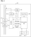
FIG. 4 illustrates a circuit block diagram of a circuit breaker such as anAFCI 405 in accordance with an exemplary embodiment of the present invention. The hardware architecture of electronics in theAFCI 405 consists of following component blocks. Amicrocontroller 407 contains all of logic for detecting and tripping theAFCI 405 for overcurrent, differential, and arc faults. An analog front end (AFE)ASIC 410 acts as an interface between a RF coupler and shunt resistance sensors and themicrocontroller 407. It contains a voltage amplifier (with 4 gain settings) for the shunt and a received signal strength indicator (RSSI) circuit for the RF coupler. ARF coupling 412 is performed using a capacitive coupling circuit connected to a 120V line voltage. Ashunt resistance 415 is on a neutral line and is used to measure the current passing through theAFCI 405. It is connected to a voltage amplifier in theASIC 410. Apower supply 420 being an AC/DC switching supply converts the 120V line voltage to 5V and 3.3V for theASIC 410, themicrocontroller 407, and a differential circuit. Atrip circuit 425 consists of a SCR and a coil and is used to trip theAFCI 405. A push-to-test (PTT)input 430 is provided as a pushbutton on theAFCI 405 which allows the user to initiate a self-test of the breaker electronics. ALED 435 is used to indicate a last trip type to the user upon breaker power-up. TheLED 435 will also indicate if theAFCI 405 failed to trip for a fault. Abreaker rating 440 is an input to themicrocontroller 407 which identifies the rating of the AFCI 405 (15A or 20A). - As seen in
FIG. 5 , it illustrates description of a neural network (NN) 505 in accordance with an exemplary embodiment of the present invention. TheNN 505 comprises an input layer 5 10, ahidden layer 515 and anoutput layer 520. - As shown in
FIG. 6 , it illustrates aneural network model 605,neural network training 610, ahidden layer 615 in accordance with an exemplary embodiment of the present invention. Theneural network model 605 is represented by its architecture that shows how to transform two or more inputs into an output. The transformation is given in the form of a learning algorithm. Theneural network training 610, i.e., training a Neural Network (NN) means finding the appropriate weights of the Neural Connections using a feedback loop. A NN training involves feedforward of data signals to generate the output and then the backpropagation of errors for gradient descent optimization. - Training data includes split - 80% training, 0% validation, 20% testing, samples of arcing, and samples of nuisance and randomized distribution of samples in split. The training method may update the weight and bias values according to optimization and minimizes a combination of squared errors and weights to determine the correct combination so as to produce a network which generalizes well. Training method parameters left set to 'default' (Note: Does not need validation data set). The performance function is Mean-squared Error. This determines the overall performance of the network by comparing the target vs. desired output.
- The
hidden layer 615 is located between the input and output of the algorithm, in which the function applies weights to the inputs and directs them through an activation function as the output. In short, the hidden layers perform nonlinear transformations of the inputs entered into the neural network. - In
FIG. 7 , it illustrates a machine learning approach 700 for arc detection in accordance with an exemplary embodiment of the present invention. At astep 705, analog signals including current, RSSI, and voltage are received. At astep 710, digital conversion of the analog signals is performed. Pre-processing of data is done into set of measurements at astep 715. Arc detection is done by Neural Network computation instead of data comparison to multiple thresholds at astep 720. At astep 725, accumulation of multiple arc detections over time goes into a decision to trip an AFCI. - With regard to
FIG. 8 , it illustrates amachine learning classifier 800 in accordance with an exemplary embodiment of the present invention. This is a high-level diagram describing the process mentioned above where signal data is analyzed and classified from specific pre-processing features at each half-cycle. Themachine learning classifier 800 comprises three stages. The first stage is sampling and automatic gain control (AGC) 805. It samples a line voltage 810(1), a load current 810(2), and a RSSI 810(3). Next stage is pre-processing 815 in which signal features are computed such as window length, signal geometry, slopes, noise etc. The final stage is a shallowneural network 820 with a predefined number of nodes. Input features are fed into a FC layer and an output is generated in terms of an arc or no arc. - With respect to
FIG. 9 , it illustrates neural network features in accordance with an exemplary embodiment of the present invention. The features for a neural network includespecific data points 905 during an event, slope of awaveform 920 at the start and end and a half-cycle duration 915. -
FIG. 10 illustratesneural network summary 1005 in accordance with an exemplary embodiment of the present invention. Theneural network summary 1005 includes 10-30 network inputs, a network size of 20-100 nodes, a network training time of minutes, a network response time of 3 milliseconds, ADC signals of load current, RSSI and an ADC sampling rate of 10-100 kHz. -
FIG. 11 illustrates a flow diagram for thesoftware code 312 running in themicrocontroller software code 312 provides classifications per half-cycle through accumulation of an inference output from a machine learning classifier. - At a
step 1105, analog signals including current and RSSI are received. At astep 1110, digital conversion of the analog signals is performed by thesoftware code 312. Next, at astep 1115, thesoftware code 312 extracts half-cycle features from the analog signals. Then in astep 1120 thesoftware code 312 runs a half-cycle feature set through a machine learning classifier. Thereafter, at a step 1125 thesoftware code 312 analyzes an output of the machine learning classifier to determine if the half-cycle was an arc or not. At astep 1130, if a no arc inference is derived, an accumulator value is decremented proportional to an amount of current. At astep 1135, if an arc inference is derived, an accumulator value is incremented proportional to an amount of current. At astep 1140, a check is made to determine if the accumulator value exceeded a max accumulation threshold. If the determination in thestep 1140 is "yes" then at astep 1145 an AFCI device is tripped. -
FIG. 12 illustrates an example of accumulator incrementing as a neural network (NN) algorithm detects electrical arc events using current and RSSI signals at each half-cycle in accordance with an exemplary embodiment of the present invention. This is an example of an accumulator incrementing 1205 as a NN algorithm detects electrical arc events using current 1210 andRSSI 1215 signals at each half-cycle. Once the accumulator reaches a defined threshold value it sends atrip signal 1220 to open a circuit breaker. The threshold value shown here is normalized to 1000. -
FIG. 13 illustrates a schematic view of a flow chart of amethod 1300 of arc fault detection by accumulation of machine learning classifications in a circuit breaker in accordance with an exemplary embodiment of the present invention. Reference is made to the elements and features described inFIGs. 1-12 . It should be appreciated that some steps are not required to be performed in any particular order, and that some steps are optional. - The
method 1300 comprises astep 1305 of providing a microcontroller including a processor and a memory. Themethod 1300 further comprises astep 1310 of providing computer-readable software code stored in the memory which, when executed by the processor, causes the microcontroller to: sample analog signals representing one or more of the following: a Received Signal Strength Indicator (RSSI) signal, a voltage signal, and a current signal, perform multiple pre-processing steps on the analog signals to derive a data set of measurements and features for every half-cycle of current passing through the circuit breaker, and input the data set into a machine learning classifier that resides in the microcontroller such that an output of the machine learning classifier is a value between 0 and 1 which represents a percent chance that the data set is from an electrical arc. Based on the value of the percent chance an accumulator value is either incremented or decremented in proportion to an amount of the current passing through the circuit breaker and if the accumulator value passes an upper threshold level, the microcontroller sends a signal output to a trip circuit which then opens the circuit breaker. - While a multi-layer neural network as a machine learning classifier is described here a range of one or more other types of machine learning classifiers or other forms of machine learning classifiers are also contemplated by the present invention. For example, other types of machine learning classifiers may be implemented based on one or more features presented above without deviating from the present invention.
- The techniques described herein can be particularly useful for arc detection in an AFCI circuit breaker. While particular embodiments are described in terms of specific configuration of an AFCI, the techniques described herein are not limited to such a limited configuration but can also be used with other configurations and types of circuit breakers.
- While embodiments of the present invention have been disclosed in exemplary forms, it will be apparent to those skilled in the art that many modifications, additions, and deletions can be made therein without departing from the scope of the invention and its equivalents, as set forth in the following claims.
- Embodiments and the various features and advantageous details thereof are explained more fully with reference to the non-limiting embodiments that are illustrated in the accompanying drawings and detailed in the following description. Descriptions of well-known starting materials, processing techniques, components and equipment are omitted so as not to unnecessarily obscure embodiments in detail. It should be understood, however, that the detailed description and the specific examples, while indicating preferred embodiments, are given by way of illustration only and not by way of limitation. Various substitutions, modifications, additions and/or rearrangements within the scope of the underlying inventive concept will become apparent to those skilled in the art from this disclosure.
- As used herein, the terms "comprises," "comprising," "includes," "including," "has," "having" or any other variation thereof, are intended to cover a non-exclusive inclusion. For example, a process, article, or apparatus that comprises a list of elements is not necessarily limited to only those elements but may include other elements not expressly listed or inherent to such process, article, or apparatus.
- Additionally, any examples or illustrations given herein are not to be regarded in any way as restrictions on, limits to, or express definitions of, any term or terms with which they are utilized. Instead, these examples or illustrations are to be regarded as being described with respect to one particular embodiment and as illustrative only. Those of ordinary skill in the art will appreciate that any term or terms with which these examples or illustrations are utilized will encompass other embodiments which may or may not be given therewith or elsewhere in the specification and all such embodiments are intended to be included within the scope of that term or terms.
- In the foregoing specification, the invention has been described with reference to specific embodiments. However, one of ordinary skill in the art appreciates that various modifications and changes can be made without departing from the scope of the invention. Accordingly, the specification and figures are to be regarded in an illustrative rather than a restrictive sense, and all such modifications are intended to be included within the scope of invention.
- Although the invention has been described with respect to specific embodiments thereof, these embodiments are merely illustrative, and not restrictive of the invention. The description herein of illustrated embodiments of the invention is not intended to be exhaustive or to limit the invention to the precise forms disclosed herein (and in particular, the inclusion of any particular embodiment, feature or function is not intended to limit the scope of the invention to such embodiment, feature or function). Rather, the description is intended to describe illustrative embodiments, features and functions in order to provide a person of ordinary skill in the art context to understand the invention without limiting the invention to any particularly described embodiment, feature or function. While specific embodiments of, and examples for, the invention are described herein for illustrative purposes only, various equivalent modifications are possible within the scope of the invention, as those skilled in the relevant art will recognize and appreciate. As indicated, these modifications may be made to the invention in light of the foregoing description of illustrated embodiments of the invention and are to be included within the scope of the invention. Thus, while the invention has been described herein with reference to particular embodiments thereof, a latitude of modification, various changes and substitutions are intended in the foregoing disclosures, and it will be appreciated that in some instances some features of embodiments of the invention will be employed without a corresponding use of other features without departing from the scope of the invention as set forth. Therefore, many modifications may be made to adapt a particular situation or material to the essential scope of the invention.
- Respective appearances of the phrases "in one embodiment," "in an embodiment," or "in a specific embodiment" or similar terminology in various places throughout this specification are not necessarily referring to the same embodiment. Furthermore, the particular features, structures, or characteristics of any particular embodiment may be combined in any suitable manner with one or more other embodiments. It is to be understood that other variations and modifications of the embodiments described and illustrated herein are possible in light of the teachings herein and are to be considered as part of the scope of the invention.
- In the description herein, numerous specific details are provided, such as examples of components and/or methods, to provide a thorough understanding of embodiments of the invention. One skilled in the relevant art will recognize, however, that an embodiment may be able to be practiced without one or more of the specific details, or with other apparatus, systems, assemblies, methods, components, materials, parts, and/or the like. In other instances, well-known structures, components, systems, materials, or operations are not specifically shown or described in detail to avoid obscuring aspects of embodiments of the invention. While the invention may be illustrated by using a particular embodiment, this is not and does not limit the invention to any particular embodiment and a person of ordinary skill in the art will recognize that additional embodiments are readily understandable and are a part of this invention.
- It will also be appreciated that one or more of the elements depicted in the drawings/figures can also be implemented in a more separated or integrated manner, or even removed or rendered as inoperable in certain cases, as is useful in accordance with a particular application.
- Benefits, other advantages, and solutions to problems have been described above with regard to specific embodiments. However, the benefits, advantages, solutions to problems, and any component(s) that may cause any benefit, advantage, or solution to occur or become more pronounced are not to be construed as a critical, required, or essential feature or component.
Claims (15)
- A circuit breaker (305; 405), comprising:a microcontroller (307; 407) including a processor (310(1)) and a memory (310(2)),computer-readable software code (312) stored in the memory which, when executed by the processor, causes the microcontroller to:sample analog signals (705) representing one or more of the following: a Received Signal Strength Indicator, RSSI, signal, a voltage signal, and a current signal;perform multiple pre-processing steps (715) on the analog signals to derive a data set of measurements and features over a period of time; andinput the data set into a machine learning classifier (325; 720) that resides in the microcontroller such that an output of the machine learning classifier is a value between 0 and 1 which represents a percent chance that the data set is from an electrical arc,wherein (725) based on the value of the percent chance an accumulator value is either incremented or decremented in proportion to an amount of the current passing through the circuit breaker and if the accumulator value passes an upper threshold level, the microcontroller sends a signal output to a trip circuit (425) which then opens the circuit breaker.
- The circuit breaker of claim 1, wherein the period of time is a duration of a half-cycle of the current passing through the circuit breaker and wherein the Received Signal Strength Indicator, RSSI, signal and the current signal come from an analog front-end ASIC circuitry.
- The circuit breaker of claim 2, wherein the analog front-end ASIC circuitry acts as an interface between a radio frequency, RF, coupler, shunt resistance sensors and the microcontroller.
- The circuit breaker of claim 1, wherein the machine learning classifier is a trained neural network.
- The circuit breaker of claim 1, wherein the microcontroller includes a logic for detecting and tripping the circuit breaker for overcurrent, differential, and arc faults.
- The circuit breaker of claim 1, wherein the analog signals data is analyzed and classified from specific pre-processing features at each half-cycle by the machine learning classifier.
- The circuit breaker of claim 1, wherein the computer-readable software code is to:digitally convert the Received Signal Strength Indicator, RSSI, signal, the voltage signal, and the current signal;extract half-cycle features from the Received Signal Strength Indicator, RSSI, signal, the voltage signal, and the current signal;run half-cycle features set through the machine learning classifier; andanalyze an output of the machine learning classifier to determine if half-cycle was an arc or not.
- The circuit breaker of claim 7, wherein if there is an arc inference, the computer-readable software code is to increment the accumulator value proportional to an amount of the current.
- The circuit breaker of claim 8, wherein the computer-readable software code is to check whether the accumulator value exceeds a max accumulator threshold and if so trip the circuit breaker.
- The circuit breaker of claim 7, wherein if there is no arc inference, the computer-readable software code is to decrement the accumulator value proportional to an amount of the current.
- A method (1300) of arc fault detection by accumulation of machine learning classifications, the method comprising:providing (1305) a microcontroller including a processor and a memory,providing (1310) computer-readable software code stored in the memory which, when executed by the processor, causes the microcontroller to:sample analog signals representing one or more of the following: a Received Signal Strength Indicator, RSSI, signal, a voltage signal, and a current signal;perform multiple pre-processing steps on the analog signals to derive a data set of measurements and features over a period of time; andinput the data set into a machine learning classifier that resides in the microcontroller such that an output of the machine learning classifier is a value between 0 and 1 which represents a percent chance that the data set is from an electrical arc,wherein based on the value of the percent chance an accumulator value is either incremented or decremented in proportion to an amount of the current passing through the circuit breaker and if the accumulator value passes an upper threshold level, the microcontroller sends a signal output to a trip circuit which then opens the circuit breaker.
- The method of claim 11, wherein the period of time is a duration of a half-cycle of the current passing through the circuit breaker and wherein the Received Signal Strength Indicator, RSSI, signal and the current signal come from an analog front-end ASIC circuitry, or wherein the analog front-end ASIC circuitry in particular acts as an interface between a radio frequency, RF, coupler, shunt resistance sensors and the microcontroller.
- The method of claim 11,wherein the machine learning classifier is a trained neural network, orwherein the microcontroller includes a logic for detecting and tripping the circuit breaker for overcurrent, differential, and arc faults, orwherein the analog signals data is analyzed and classified from specific pre-processing features at each half-cycle by the machine learning classifier.
- The method of claim 11, wherein the computer-readable software code is to:digitally convert the Received Signal Strength Indicator, RSSI, signal, the voltage signal, and the current signal;extract half-cycle features from the Received Signal Strength Indicator, RSSI, signal, the voltage signal, and the current signal;run half-cycle features set through the machine learning classifier; andanalyze an output of the machine learning classifier to determine if half-cycle was an arc or not.
- The method of claim 14,wherein if there is an arc inference, the computer-readable software code is to increment the accumulator value proportional to an amount of the current, wherein in particular the computer-readable software code is to check whether the accumulator value exceeds a max accumulator threshold and if so trip the circuit breaker, orwherein if there is no arc inference, the computer-readable software code is to decrement the accumulator value proportional to an amount of the current.
Applications Claiming Priority (2)
| Application Number | Priority Date | Filing Date | Title |
|---|---|---|---|
| US17/163,997 US20220247163A1 (en) | 2021-02-01 | 2021-02-01 | Arc fault detection by accumulation of machine learning classifications in a circuit breaker |
| PCT/US2022/012654 WO2022164663A1 (en) | 2021-02-01 | 2022-01-17 | Arc fault detection by accumulation of machine learning classifications in a circuit breaker |
Publications (2)
| Publication Number | Publication Date |
|---|---|
| EP4244637A1 EP4244637A1 (en) | 2023-09-20 |
| EP4244637B1 true EP4244637B1 (en) | 2024-07-10 |
Family
ID=80168364
Family Applications (1)
| Application Number | Title | Priority Date | Filing Date |
|---|---|---|---|
| EP22702383.5A Active EP4244637B1 (en) | 2021-02-01 | 2022-01-17 | Arc fault detection by accumulation of machine learning classifications in a circuit breaker |
Country Status (5)
| Country | Link |
|---|---|
| US (1) | US20220247163A1 (en) |
| EP (1) | EP4244637B1 (en) |
| CA (1) | CA3204006A1 (en) |
| MX (1) | MX2023008934A (en) |
| WO (1) | WO2022164663A1 (en) |
Families Citing this family (9)
| Publication number | Priority date | Publication date | Assignee | Title |
|---|---|---|---|---|
| JP7820641B2 (en) * | 2022-03-11 | 2026-02-26 | ミネベアパワーデバイス株式会社 | Method for estimating partial discharge causes of power semiconductor module, and device for estimating partial discharge causes of power semiconductor module |
| EP4511932A4 (en) * | 2022-04-22 | 2026-04-08 | Aclara Tech Llc | Series arc detection firmware |
| CN115168079B (en) * | 2022-09-08 | 2022-12-02 | 深圳市恒运昌真空技术有限公司 | Dual-processor device and control method thereof |
| US12535538B2 (en) * | 2023-08-11 | 2026-01-27 | Siemens Industry, Inc. | Active detection of an arc fault |
| CN117872122B (en) * | 2024-01-24 | 2024-09-17 | 广东电网有限责任公司江门供电局 | Mechanical fault diagnosis method based on high-voltage circuit breaker |
| KR102906080B1 (en) * | 2024-02-02 | 2025-12-29 | 중앙대학교 산학협력단 | Dc series arc filure diagnosis apparatus using artificial machine learning |
| US20260018358A1 (en) * | 2024-07-11 | 2026-01-15 | Siemens Industry, Inc. | Active arc fault circuit interrupters with solid-state components |
| DE102024208163A1 (en) * | 2024-08-28 | 2026-03-05 | Siemens Aktiengesellschaft | Optimized fault detection in a power grid |
| CN119479249B (en) * | 2025-01-16 | 2025-03-28 | 核工业西南勘察设计研究院有限公司 | Electric fire early warning method and system for TOD building |
Family Cites Families (5)
| Publication number | Priority date | Publication date | Assignee | Title |
|---|---|---|---|---|
| DE4333257C2 (en) * | 1993-09-27 | 1997-09-04 | Siemens Ag | Method of obtaining an error flag signal |
| GB0104763D0 (en) * | 2001-02-27 | 2001-04-18 | Smiths Group Plc | Arc detection |
| US7720619B2 (en) * | 2006-08-04 | 2010-05-18 | Schweitzer Engineering Laboratories, Inc. | Systems and methods for detecting high-impedance faults in a multi-grounded power distribution system |
| US8023235B2 (en) * | 2006-10-31 | 2011-09-20 | Siemens Industry, Inc. | Multifunctional residential circuit breaker |
| US9995796B1 (en) * | 2013-05-23 | 2018-06-12 | National Technology & Engineering Solutions Of Sandia, Llc | Identifying an arc-fault type in photovoltaic arrays |
-
2021
- 2021-02-01 US US17/163,997 patent/US20220247163A1/en not_active Abandoned
-
2022
- 2022-01-17 EP EP22702383.5A patent/EP4244637B1/en active Active
- 2022-01-17 WO PCT/US2022/012654 patent/WO2022164663A1/en not_active Ceased
- 2022-01-17 MX MX2023008934A patent/MX2023008934A/en unknown
- 2022-01-17 CA CA3204006A patent/CA3204006A1/en active Pending
Also Published As
| Publication number | Publication date |
|---|---|
| MX2023008934A (en) | 2023-08-10 |
| CA3204006A1 (en) | 2022-08-04 |
| EP4244637A1 (en) | 2023-09-20 |
| US20220247163A1 (en) | 2022-08-04 |
| WO2022164663A1 (en) | 2022-08-04 |
Similar Documents
| Publication | Publication Date | Title |
|---|---|---|
| US20220247163A1 (en) | Arc fault detection by accumulation of machine learning classifications in a circuit breaker | |
| JP5073472B2 (en) | Series arc fault current breaker and method | |
| JP6116495B2 (en) | DC arc detection apparatus and method | |
| US5537327A (en) | Method and apparatus for detecting high-impedance faults in electrical power systems | |
| US7796366B2 (en) | AC arc fault detection and protection | |
| EP2207246B1 (en) | Earth leakage detection circuit | |
| US20090161270A1 (en) | Industrial arc fault circuit interrupter and method of detecting arcing conditions | |
| JP6431123B2 (en) | Analog signal detection circuit | |
| CN111796202B (en) | Method and device for fault detection of transmission lines of power transmission system | |
| CN108885237A (en) | Method and apparatus for detecting the arc fault in electrical system | |
| KR101956571B1 (en) | Earth leakage circuit breaker | |
| US20180074112A1 (en) | Device for detecting an electric arc based on its acoustic signature | |
| US20030231449A1 (en) | Circuit breaker for detecting overload | |
| Jose et al. | Integrated approach based third zone protection during stressed system conditions | |
| CN110323726B (en) | A kind of DC distribution network adaptive line protection method and device | |
| KR20150081943A (en) | Earth leakage circuit breaker | |
| KR101616797B1 (en) | Earth leakage circuit breaker | |
| US12394973B2 (en) | Apparatus and method of detecting and classifying faults in circuit interrupter in microseconds | |
| CA3239432A1 (en) | Dynamic counterbalance adjustment for telescoping cranes | |
| CN116298663A (en) | A method and system for identifying faults inside and outside the area of a highly sensitive hybrid direct current line | |
| US20260018358A1 (en) | Active arc fault circuit interrupters with solid-state components | |
| RU2400899C1 (en) | Method of ultra-rapid emergency protection of ac power system elements and device for its realisation | |
| AU2022470561A1 (en) | Method, device and equipment for detecting an electric arc fault | |
| WO2026046841A1 (en) | Optimized fault detection in a power grid | |
| Abdallah et al. | Review of protection approaches for discrimination between internal fault and inrush current in electric power transformers |
Legal Events
| Date | Code | Title | Description |
|---|---|---|---|
| STAA | Information on the status of an ep patent application or granted ep patent |
Free format text: STATUS: UNKNOWN |
|
| STAA | Information on the status of an ep patent application or granted ep patent |
Free format text: STATUS: THE INTERNATIONAL PUBLICATION HAS BEEN MADE |
|
| PUAI | Public reference made under article 153(3) epc to a published international application that has entered the european phase |
Free format text: ORIGINAL CODE: 0009012 |
|
| STAA | Information on the status of an ep patent application or granted ep patent |
Free format text: STATUS: REQUEST FOR EXAMINATION WAS MADE |
|
| 17P | Request for examination filed |
Effective date: 20230614 |
|
| AK | Designated contracting states |
Kind code of ref document: A1 Designated state(s): AL AT BE BG CH CY CZ DE DK EE ES FI FR GB GR HR HU IE IS IT LI LT LU LV MC MK MT NL NO PL PT RO RS SE SI SK SM TR |
|
| GRAP | Despatch of communication of intention to grant a patent |
Free format text: ORIGINAL CODE: EPIDOSNIGR1 |
|
| STAA | Information on the status of an ep patent application or granted ep patent |
Free format text: STATUS: GRANT OF PATENT IS INTENDED |
|
| INTG | Intention to grant announced |
Effective date: 20240318 |
|
| DAV | Request for validation of the european patent (deleted) | ||
| DAX | Request for extension of the european patent (deleted) | ||
| GRAS | Grant fee paid |
Free format text: ORIGINAL CODE: EPIDOSNIGR3 |
|
| GRAA | (expected) grant |
Free format text: ORIGINAL CODE: 0009210 |
|
| STAA | Information on the status of an ep patent application or granted ep patent |
Free format text: STATUS: THE PATENT HAS BEEN GRANTED |
|
| AK | Designated contracting states |
Kind code of ref document: B1 Designated state(s): AL AT BE BG CH CY CZ DE DK EE ES FI FR GB GR HR HU IE IS IT LI LT LU LV MC MK MT NL NO PL PT RO RS SE SI SK SM TR |
|
| REG | Reference to a national code |
Ref country code: CH Ref legal event code: EP |
|
| REG | Reference to a national code |
Ref country code: DE Ref legal event code: R096 Ref document number: 602022004486 Country of ref document: DE |
|
| REG | Reference to a national code |
Ref country code: LT Ref legal event code: MG9D |
|
| REG | Reference to a national code |
Ref country code: NL Ref legal event code: MP Effective date: 20240710 |
|
| PG25 | Lapsed in a contracting state [announced via postgrant information from national office to epo] |
Ref country code: PT Free format text: LAPSE BECAUSE OF FAILURE TO SUBMIT A TRANSLATION OF THE DESCRIPTION OR TO PAY THE FEE WITHIN THE PRESCRIBED TIME-LIMIT Effective date: 20241111 |
|
| REG | Reference to a national code |
Ref country code: AT Ref legal event code: MK05 Ref document number: 1702490 Country of ref document: AT Kind code of ref document: T Effective date: 20240710 |
|
| PG25 | Lapsed in a contracting state [announced via postgrant information from national office to epo] |
Ref country code: NL Free format text: LAPSE BECAUSE OF FAILURE TO SUBMIT A TRANSLATION OF THE DESCRIPTION OR TO PAY THE FEE WITHIN THE PRESCRIBED TIME-LIMIT Effective date: 20240710 |
|
| PG25 | Lapsed in a contracting state [announced via postgrant information from national office to epo] |
Ref country code: PT Free format text: LAPSE BECAUSE OF FAILURE TO SUBMIT A TRANSLATION OF THE DESCRIPTION OR TO PAY THE FEE WITHIN THE PRESCRIBED TIME-LIMIT Effective date: 20241111 Ref country code: NL Free format text: LAPSE BECAUSE OF FAILURE TO SUBMIT A TRANSLATION OF THE DESCRIPTION OR TO PAY THE FEE WITHIN THE PRESCRIBED TIME-LIMIT Effective date: 20240710 |
|
| PG25 | Lapsed in a contracting state [announced via postgrant information from national office to epo] |
Ref country code: NO Free format text: LAPSE BECAUSE OF FAILURE TO SUBMIT A TRANSLATION OF THE DESCRIPTION OR TO PAY THE FEE WITHIN THE PRESCRIBED TIME-LIMIT Effective date: 20241010 |
|
| PG25 | Lapsed in a contracting state [announced via postgrant information from national office to epo] |
Ref country code: GR Free format text: LAPSE BECAUSE OF FAILURE TO SUBMIT A TRANSLATION OF THE DESCRIPTION OR TO PAY THE FEE WITHIN THE PRESCRIBED TIME-LIMIT Effective date: 20241011 Ref country code: FI Free format text: LAPSE BECAUSE OF FAILURE TO SUBMIT A TRANSLATION OF THE DESCRIPTION OR TO PAY THE FEE WITHIN THE PRESCRIBED TIME-LIMIT Effective date: 20240710 Ref country code: PL Free format text: LAPSE BECAUSE OF FAILURE TO SUBMIT A TRANSLATION OF THE DESCRIPTION OR TO PAY THE FEE WITHIN THE PRESCRIBED TIME-LIMIT Effective date: 20240710 |
|
| PG25 | Lapsed in a contracting state [announced via postgrant information from national office to epo] |
Ref country code: BG Free format text: LAPSE BECAUSE OF FAILURE TO SUBMIT A TRANSLATION OF THE DESCRIPTION OR TO PAY THE FEE WITHIN THE PRESCRIBED TIME-LIMIT Effective date: 20240710 |
|
| PG25 | Lapsed in a contracting state [announced via postgrant information from national office to epo] |
Ref country code: LV Free format text: LAPSE BECAUSE OF FAILURE TO SUBMIT A TRANSLATION OF THE DESCRIPTION OR TO PAY THE FEE WITHIN THE PRESCRIBED TIME-LIMIT Effective date: 20240710 |
|
| PG25 | Lapsed in a contracting state [announced via postgrant information from national office to epo] |
Ref country code: IS Free format text: LAPSE BECAUSE OF FAILURE TO SUBMIT A TRANSLATION OF THE DESCRIPTION OR TO PAY THE FEE WITHIN THE PRESCRIBED TIME-LIMIT Effective date: 20241110 Ref country code: AT Free format text: LAPSE BECAUSE OF FAILURE TO SUBMIT A TRANSLATION OF THE DESCRIPTION OR TO PAY THE FEE WITHIN THE PRESCRIBED TIME-LIMIT Effective date: 20240710 |
|
| PG25 | Lapsed in a contracting state [announced via postgrant information from national office to epo] |
Ref country code: HR Free format text: LAPSE BECAUSE OF FAILURE TO SUBMIT A TRANSLATION OF THE DESCRIPTION OR TO PAY THE FEE WITHIN THE PRESCRIBED TIME-LIMIT Effective date: 20240710 |
|
| PG25 | Lapsed in a contracting state [announced via postgrant information from national office to epo] |
Ref country code: ES Free format text: LAPSE BECAUSE OF FAILURE TO SUBMIT A TRANSLATION OF THE DESCRIPTION OR TO PAY THE FEE WITHIN THE PRESCRIBED TIME-LIMIT Effective date: 20240710 Ref country code: RS Free format text: LAPSE BECAUSE OF FAILURE TO SUBMIT A TRANSLATION OF THE DESCRIPTION OR TO PAY THE FEE WITHIN THE PRESCRIBED TIME-LIMIT Effective date: 20241010 |
|
| PG25 | Lapsed in a contracting state [announced via postgrant information from national office to epo] |
Ref country code: RS Free format text: LAPSE BECAUSE OF FAILURE TO SUBMIT A TRANSLATION OF THE DESCRIPTION OR TO PAY THE FEE WITHIN THE PRESCRIBED TIME-LIMIT Effective date: 20241010 Ref country code: PL Free format text: LAPSE BECAUSE OF FAILURE TO SUBMIT A TRANSLATION OF THE DESCRIPTION OR TO PAY THE FEE WITHIN THE PRESCRIBED TIME-LIMIT Effective date: 20240710 Ref country code: NO Free format text: LAPSE BECAUSE OF FAILURE TO SUBMIT A TRANSLATION OF THE DESCRIPTION OR TO PAY THE FEE WITHIN THE PRESCRIBED TIME-LIMIT Effective date: 20241010 Ref country code: LV Free format text: LAPSE BECAUSE OF FAILURE TO SUBMIT A TRANSLATION OF THE DESCRIPTION OR TO PAY THE FEE WITHIN THE PRESCRIBED TIME-LIMIT Effective date: 20240710 Ref country code: IS Free format text: LAPSE BECAUSE OF FAILURE TO SUBMIT A TRANSLATION OF THE DESCRIPTION OR TO PAY THE FEE WITHIN THE PRESCRIBED TIME-LIMIT Effective date: 20241110 Ref country code: HR Free format text: LAPSE BECAUSE OF FAILURE TO SUBMIT A TRANSLATION OF THE DESCRIPTION OR TO PAY THE FEE WITHIN THE PRESCRIBED TIME-LIMIT Effective date: 20240710 Ref country code: GR Free format text: LAPSE BECAUSE OF FAILURE TO SUBMIT A TRANSLATION OF THE DESCRIPTION OR TO PAY THE FEE WITHIN THE PRESCRIBED TIME-LIMIT Effective date: 20241011 Ref country code: FI Free format text: LAPSE BECAUSE OF FAILURE TO SUBMIT A TRANSLATION OF THE DESCRIPTION OR TO PAY THE FEE WITHIN THE PRESCRIBED TIME-LIMIT Effective date: 20240710 Ref country code: ES Free format text: LAPSE BECAUSE OF FAILURE TO SUBMIT A TRANSLATION OF THE DESCRIPTION OR TO PAY THE FEE WITHIN THE PRESCRIBED TIME-LIMIT Effective date: 20240710 Ref country code: BG Free format text: LAPSE BECAUSE OF FAILURE TO SUBMIT A TRANSLATION OF THE DESCRIPTION OR TO PAY THE FEE WITHIN THE PRESCRIBED TIME-LIMIT Effective date: 20240710 Ref country code: AT Free format text: LAPSE BECAUSE OF FAILURE TO SUBMIT A TRANSLATION OF THE DESCRIPTION OR TO PAY THE FEE WITHIN THE PRESCRIBED TIME-LIMIT Effective date: 20240710 |
|
| REG | Reference to a national code |
Ref country code: DE Ref legal event code: R097 Ref document number: 602022004486 Country of ref document: DE |
|
| PG25 | Lapsed in a contracting state [announced via postgrant information from national office to epo] |
Ref country code: DK Free format text: LAPSE BECAUSE OF FAILURE TO SUBMIT A TRANSLATION OF THE DESCRIPTION OR TO PAY THE FEE WITHIN THE PRESCRIBED TIME-LIMIT Effective date: 20240710 Ref country code: RO Free format text: LAPSE BECAUSE OF FAILURE TO SUBMIT A TRANSLATION OF THE DESCRIPTION OR TO PAY THE FEE WITHIN THE PRESCRIBED TIME-LIMIT Effective date: 20240710 Ref country code: SM Free format text: LAPSE BECAUSE OF FAILURE TO SUBMIT A TRANSLATION OF THE DESCRIPTION OR TO PAY THE FEE WITHIN THE PRESCRIBED TIME-LIMIT Effective date: 20240710 |
|
| PG25 | Lapsed in a contracting state [announced via postgrant information from national office to epo] |
Ref country code: EE Free format text: LAPSE BECAUSE OF FAILURE TO SUBMIT A TRANSLATION OF THE DESCRIPTION OR TO PAY THE FEE WITHIN THE PRESCRIBED TIME-LIMIT Effective date: 20240710 |
|
| PG25 | Lapsed in a contracting state [announced via postgrant information from national office to epo] |
Ref country code: CZ Free format text: LAPSE BECAUSE OF FAILURE TO SUBMIT A TRANSLATION OF THE DESCRIPTION OR TO PAY THE FEE WITHIN THE PRESCRIBED TIME-LIMIT Effective date: 20240710 |
|
| PG25 | Lapsed in a contracting state [announced via postgrant information from national office to epo] |
Ref country code: SK Free format text: LAPSE BECAUSE OF FAILURE TO SUBMIT A TRANSLATION OF THE DESCRIPTION OR TO PAY THE FEE WITHIN THE PRESCRIBED TIME-LIMIT Effective date: 20240710 |
|
| PLBE | No opposition filed within time limit |
Free format text: ORIGINAL CODE: 0009261 |
|
| STAA | Information on the status of an ep patent application or granted ep patent |
Free format text: STATUS: NO OPPOSITION FILED WITHIN TIME LIMIT |
|
| 26N | No opposition filed |
Effective date: 20250411 |
|
| REG | Reference to a national code |
Ref country code: CH Ref legal event code: PL |
|
| PG25 | Lapsed in a contracting state [announced via postgrant information from national office to epo] |
Ref country code: SE Free format text: LAPSE BECAUSE OF FAILURE TO SUBMIT A TRANSLATION OF THE DESCRIPTION OR TO PAY THE FEE WITHIN THE PRESCRIBED TIME-LIMIT Effective date: 20240710 |
|
| PG25 | Lapsed in a contracting state [announced via postgrant information from national office to epo] |
Ref country code: MC Free format text: LAPSE BECAUSE OF FAILURE TO SUBMIT A TRANSLATION OF THE DESCRIPTION OR TO PAY THE FEE WITHIN THE PRESCRIBED TIME-LIMIT Effective date: 20240710 Ref country code: LU Free format text: LAPSE BECAUSE OF NON-PAYMENT OF DUE FEES Effective date: 20250117 |
|
| PG25 | Lapsed in a contracting state [announced via postgrant information from national office to epo] |
Ref country code: BE Free format text: LAPSE BECAUSE OF NON-PAYMENT OF DUE FEES Effective date: 20250131 |
|
| PG25 | Lapsed in a contracting state [announced via postgrant information from national office to epo] |
Ref country code: CH Free format text: LAPSE BECAUSE OF NON-PAYMENT OF DUE FEES Effective date: 20250131 |
|
| REG | Reference to a national code |
Ref country code: BE Ref legal event code: MM Effective date: 20250131 |
|
| PG25 | Lapsed in a contracting state [announced via postgrant information from national office to epo] |
Ref country code: IE Free format text: LAPSE BECAUSE OF NON-PAYMENT OF DUE FEES Effective date: 20250117 |
|
| PGFP | Annual fee paid to national office [announced via postgrant information from national office to epo] |
Ref country code: GB Payment date: 20260210 Year of fee payment: 5 |
|
| PGFP | Annual fee paid to national office [announced via postgrant information from national office to epo] |
Ref country code: DE Payment date: 20260320 Year of fee payment: 5 |
|
| PGFP | Annual fee paid to national office [announced via postgrant information from national office to epo] |
Ref country code: IT Payment date: 20260127 Year of fee payment: 5 |
|
| PGFP | Annual fee paid to national office [announced via postgrant information from national office to epo] |
Ref country code: FR Payment date: 20260122 Year of fee payment: 5 |