EP4244575B1 - Method for inspecting hollow glass products of glass product material - Google Patents
Method for inspecting hollow glass products of glass product material Download PDFInfo
- Publication number
- EP4244575B1 EP4244575B1 EP21806425.1A EP21806425A EP4244575B1 EP 4244575 B1 EP4244575 B1 EP 4244575B1 EP 21806425 A EP21806425 A EP 21806425A EP 4244575 B1 EP4244575 B1 EP 4244575B1
- Authority
- EP
- European Patent Office
- Prior art keywords
- glass
- product
- glass product
- thickness distribution
- products
- Prior art date
- Legal status (The legal status is an assumption and is not a legal conclusion. Google has not performed a legal analysis and makes no representation as to the accuracy of the status listed.)
- Active
Links
Images

Classifications
-
- G—PHYSICS
- G01—MEASURING; TESTING
- G01B—MEASURING LENGTH, THICKNESS OR SIMILAR LINEAR DIMENSIONS; MEASURING ANGLES; MEASURING AREAS; MEASURING IRREGULARITIES OF SURFACES OR CONTOURS
- G01B21/00—Measuring arrangements or details thereof, where the measuring technique is not covered by the other groups of this subclass, unspecified or not relevant
- G01B21/02—Measuring arrangements or details thereof, where the measuring technique is not covered by the other groups of this subclass, unspecified or not relevant for measuring length, width, or thickness
- G01B21/08—Measuring arrangements or details thereof, where the measuring technique is not covered by the other groups of this subclass, unspecified or not relevant for measuring length, width, or thickness for measuring thickness
- G01B21/085—Measuring arrangements or details thereof, where the measuring technique is not covered by the other groups of this subclass, unspecified or not relevant for measuring length, width, or thickness for measuring thickness using thermal means
-
- G—PHYSICS
- G06—COMPUTING OR CALCULATING; COUNTING
- G06T—IMAGE DATA PROCESSING OR GENERATION, IN GENERAL
- G06T7/00—Image analysis
- G06T7/0002—Inspection of images, e.g. flaw detection
- G06T7/0004—Industrial image inspection
-
- C—CHEMISTRY; METALLURGY
- C03—GLASS; MINERAL OR SLAG WOOL
- C03B—MANUFACTURE, SHAPING, OR SUPPLEMENTARY PROCESSES
- C03B9/00—Blowing glass; Production of hollow glass articles
- C03B9/30—Details of blowing glass; Use of materials for the moulds
- C03B9/40—Gearing or controlling mechanisms specially adapted for glass-blowing machines
- C03B9/41—Electric or electronic systems
-
- G—PHYSICS
- G01—MEASURING; TESTING
- G01B—MEASURING LENGTH, THICKNESS OR SIMILAR LINEAR DIMENSIONS; MEASURING ANGLES; MEASURING AREAS; MEASURING IRREGULARITIES OF SURFACES OR CONTOURS
- G01B11/00—Measuring arrangements characterised by the use of optical techniques
- G01B11/02—Measuring arrangements characterised by the use of optical techniques for measuring length, width or thickness
- G01B11/06—Measuring arrangements characterised by the use of optical techniques for measuring length, width or thickness for measuring thickness ; e.g. of sheet material
-
- G—PHYSICS
- G01—MEASURING; TESTING
- G01N—INVESTIGATING OR ANALYSING MATERIALS BY DETERMINING THEIR CHEMICAL OR PHYSICAL PROPERTIES
- G01N25/00—Investigating or analyzing materials by the use of thermal means
- G01N25/72—Investigating presence of flaws
-
- C—CHEMISTRY; METALLURGY
- C03—GLASS; MINERAL OR SLAG WOOL
- C03B—MANUFACTURE, SHAPING, OR SUPPLEMENTARY PROCESSES
- C03B25/00—Annealing glass products
- C03B25/04—Annealing glass products in a continuous way
- C03B25/06—Annealing glass products in a continuous way with horizontal displacement of the glass products
-
- G—PHYSICS
- G06—COMPUTING OR CALCULATING; COUNTING
- G06T—IMAGE DATA PROCESSING OR GENERATION, IN GENERAL
- G06T2207/00—Indexing scheme for image analysis or image enhancement
- G06T2207/10—Image acquisition modality
- G06T2207/10048—Infrared image
-
- G—PHYSICS
- G06—COMPUTING OR CALCULATING; COUNTING
- G06T—IMAGE DATA PROCESSING OR GENERATION, IN GENERAL
- G06T2207/00—Indexing scheme for image analysis or image enhancement
- G06T2207/30—Subject of image; Context of image processing
- G06T2207/30108—Industrial image inspection
- G06T2207/30116—Casting
Definitions
- the invention relates to a method for inspecting hollow glass products of glass product material, wherein the glass products are manufactured by:
- the invention further relates to a method for producing and inspecting hollow glass products of glass product material, wherein the glass products are manufactured by:
- the invention relates to a system for producing and inspecting glass products of glass product material according to the above-mentioned method, wherein the system comprises:
- the invention relates to a system for inspecting glass products of glass product material according to the above-mentioned method, wherein the system comprises:
- Such methods and systems are known per se, for instance from WO-2019133504A1 .
- images of the still-hot just-manufactured glass products are made. Due to the sensors being set up around the glass product, with the images a full revolution of the product is covered. The making of such a group of images is carried out repeatedly at different points of time. On each of the images, the intensity of the infrared radiation is visible. By comparing two images made at different points of time of a same part of the product, a decrease of the intensity can be established. If the intensity decreases relatively slowly, it is established that the glass material at that spot is relatively thick. If the intensity decreases relatively fast, it is established that the glass material at that spot is relatively thin. In this manner, a lateral glass thickness distribution of the glass product can be determined. A disadvantage is that this method is relatively inaccurate.
- This just-mentioned lateral glass thickness distribution also referred to by the abbreviation LGD (Lateral Glass Distribution)
- LGD Lateral Glass Distribution
- This LGD can for instance be obtained by measuring glass wall thicknesses at a particular height h and performing the thickness measurements around the whole circumference of the product. All wall thicknesses of the whole product are the Total Lateral Glass Distribution of the product.
- a single wall thickness of the product at a defined height h and angle phi (polar coordinates) is an element of the set of wall thicknesses: Lateral Glass Distribution LGD(h,phi). The number of elements in the LGD depends on the, freely to be chosen, measuring resolution of the height and the angle.
- the LGD is a very important parameter for the quality of the glass product.
- the strength of the product is chiefly determined by the thinnest part of a glass wall. In order to prevent breakage in the normal use of the product, the LGD must comply with the specifications of a producer.
- the variation of the Lateral Glass Distribution can range from 35% to 55% of the average glass wall thickness.
- this glass thickness variation is compensated for by making the glass wall of extra thick design. As a result, not only does the product become heavier (more glass), but also more base materials are used, it takes more energy to produce the product (melting and annealing) and the transport costs of the glass product become higher due to the extra weight.
- the design of the product can be adjusted to have a thinner (more constant) glass wall thickness.
- the product becomes lighter, the production costs fall proportionally, and so do the transport costs (as well as the CO 2 , NO x emissions depending thereon).
- a sensor that is able to determine the LGD in the glass forming process is requisite.
- the root causes of the variation of the LGD can be investigated, for instance by ascertaining which process settings or parts of the process are responsible for an unduly large variation in the LGD.
- the responsible process steps can be improved, for instance by optimizing the setting by using the measuring data of the sensor. This may also be done automatically with a feedback system (FeedBack loop) to automate the optimum settings so as to obtain a minimal variation of the LGD. Also, improvements may be incorporated in the responsible process steps, to minimize the variation of the LGD.
- Object of the invention is to improve the known inspection process and possibly, on the basis of the improved inspection process, to improve the production process.
- the method according to the invention is characterised in that the sensors used in step d. are sensitive to infrared light having at least one frequency where the glass product is transparent to the infrared light so that an image of the plurality of images both shows a side of the glass product that faces the sensor with which the image has been made and shows a side of the glass product, located opposite the side, that faces away from the sensor with which the image has been made, wherein the plurality of images cover a first area of the glass product that extends around an axial axis of the product and wherein in step e. the plurality of images are processed in combination according to the principle of tomography for obtaining a lateral glass thickness distribution of the glass that is in the area.
- Transparent is here understood to mean sufficiently transparent so that an image of the plurality of images both shows a side of the glass product that faces the sensor with which the image has been made and shows a side of the glass product, located opposite the side, that faces away from the sensor with which the image has been made.
- the camera can hence see through the product, but does see the inner and outer surfaces of the product.
- each sensor is sensitive to light in the spectrum to which the glass is transparent, more particularly that the sensor is sensitive to light having a bandwidth of 900nm - 3500nm, still more particularly that the sensor is sensitive to light having a bandwidth of 900nm - 1900nm.
- the invention is based on the insight that in an image, by detection of infrared light to which the hollow glass product is transparent, both a side of the glass product is shown that faces the sensor and a side of the glass product, located opposite the side, that faces away from the sensor.
- the plurality of images are made, however, it is possible, according to the principle of tomography, to determine information that represents the glass thickness of the material. This information about the glass thickness can then be determined for at least the whole first area that extends around the glass product. With infrared radiation, thus, indirectly the glass thickness is determined. The amount of radiation depends on the temperature (distribution) of the glass and the thickness of the glass (also material properties). In an industrial process the temperature is mostly constant, so that the measurements can be calibrated. The sensor sees a combination of the front glass wall and the rear glass wall. By tomography, this front glass wall and rear glass wall as well as their surfaces can be distinctly detected.
- a glass thickness distribution is within predetermined limits. If this is not the case, for instance the product may be rejected but it is also possible to adjust a parameter of the glass production process, such as for instance the temperature with which the glass product material is heated in step a. or the forming of the heated glass product material into the glass product in step b. In this forming, for instance moulds may be utilized. Adjusting (adapting) step b. may then for instance consist in replacing a mould with a new mould. Also, in step b. troughs may be utilized through which the glass product material flows towards a mould. Such troughs may, for instance upon an established deviation of a glass thickness distribution, be lubricated with a lubricant.
- step b. are carried out manually.
- glass products are typically produced parallel to each other in a plurality of moulds.
- the glass thickness distributions can then be determined.
- the glass thickness distributions of products that have been produced with another mould are then determined separately. If one of the moulds exhibits a deviation resulting in a deviation in glass thickness distribution, this can be established separately for that mould on the basis of a glass thickness distribution of a product that has been manufactured in that mould.
- a deviation in at least one trough supplying a glass gob in each case exclusively to one of the moulds can be detected by detection of a deviation in the associated at least one glass thickness distribution.
- these may be corrected, for instance automatically, for instance by readjusting a position and/or orientation of a trough with respect to a mould or providing a trough with a lubricant.
- a mould may be replaced.
- a plurality of the steps b. are carried out parallel to each other for producing parallel to each other a plurality of the products in a plurality of production flows which each comprise a step b., wherein each determined glass thickness distribution of a product is related to the production flow in which the respective product has been manufactured, more particularly wherein in an automatic manner a production flow is controlled on the basis of at least one glass thickness distribution of at least one product that has been manufactured in the respective product flow.
- Controlling of a production flow is here understood to mean controlling of hardware with the aid of which the product is manufactured in the production flow.
- Such controlling can consist in, for instance, setting a position and/or orientation of at least one trough and/or a mould, supplying a lubricant to the at least one trough and/or replacing a mould.
- the method is thus characterised in that a plurality of the steps b. are carried out parallel to each other for producing parallel to each other a plurality of the products in a plurality of production flows, wherein in each production flow a step b.
- each determined glass thickness distribution of a product is related to the production flow in which the respective product has been manufactured, more particularly wherein on the basis of a glass thickness distribution of a particular product the production flow is controlled (manually or automatically) on the basis of at least one glass thickness distribution of at least one product which has been manufactured in the respective product flow.
- the glass thickness distribution comprises absolute values of the glass thickness distribution.
- the glass thickness distribution solely indicates relative variations in glass thickness.
- each image of the plurality of images both shows a side of the glass product that faces the at least one sensor with which the image has been made and shows a side of the glass product, located opposite the side, that faces away from the at least one sensor with which the image has been made.
- step e. can be carried out particularly accurately.
- steps d. and e. are carried out repeatedly for obtaining a lateral glass thickness distribution in a second area of the glass product that extends around an axial axis of the product, with the first and second area being staggered with respect to each other in the axial direction.
- the first and second area may partly overlap, adjoin each other, or be apart from each other so that in the latter case between the first and second area is an area that is not covered by the first and second area.
- Characteristic of these areas is that the glass thickness distribution LGD (h.phi) for the first area can take values of h that cannot be taken in the glass thickness distribution of the second area, since the first and second area are staggered with respect to each other in axial direction. It holds, preferably, that the steps d. and e. are respectively carried out repeatedly at least three times for respectively obtaining lateral glass thickness distributions in respectively at least three mutually different areas which each extend around the axial axis and are staggered with respect to each other in axial direction and which preferably in combination cover, at least substantially, the whole glass product.
- the glass thickness distribution of the whole product can be mapped. Also, it is possible that the first area covers the whole product.
- the method for producing and inspecting hollow glass products is further characterised in that the sensors used in step d. are sensitive to infrared light having at least one frequency where the glass product is transparent to the infrared light so that an image of the plurality of images both shows a side of the glass product that faces the sensor with which the image has been made and shows a side of the glass product, located opposite the side, that faces away from the sensor with which the image has been made, wherein the plurality of images cover a first area of the glass product that extends around an axial axis of the product and wherein in step e. the plurality of images are processed in combination according to the principle of tomography for obtaining a lateral glass thickness distribution of the glass that is in the area.
- the system for producing and inspecting glass products is further characterised in that the sensors used in step d. are sensitive to infrared light having at least one frequency where the glass product is transparent to the infrared light so that an image of the plurality of images both shows a side of the glass product that faces the sensor with which the image has been made and shows a side of the glass product, located opposite the side, that faces away from the sensor with which the image has been made, wherein the plurality of images cover a first area of the glass product that extends around an axial axis of the product and wherein the processing unit is further configured for carrying out step e. of the method according to the characterising portion of claim 1.
- the system for inspecting glass products is further characterised in that the sensors used in step d. are sensitive to infrared light having at least one frequency where the glass product is transparent to the infrared light so that an image of the plurality of images both shows a side of the glass product that faces the sensor with which the image has been made and shows a side of the glass product, located opposite the side, that faces away from the sensor with which the image has been made, wherein the plurality of images cover a first area of the glass product that extends around an axial axis of the product and wherein the processing unit is further configured for carrying out step e. of the method according to the characterising portion of claim 1.
- FIG. 1 a system according to the invention is indicated for carrying out a method according to the invention.
- the system comprises a schematically shown heating apparatus 2 for heating glass product material so that the glass product material enters a molten state.
- the molten material is transported to a product forming apparatus 3.
- other materials may be supplied to the product forming apparatus 3 if this is necessary, such as other materials and/or semimanufactures.
- the glass product 4.i is here manufactured after the glass product 4.i-1.
- the product forming apparatus 3 in this example includes for this purpose one mould, known per se, 104 (shown schematically in Fig.
- the product forming apparatus 3 comprises blowing means (not shown) for blowing or pushing the glass product material into the mould for obtaining the final shape of the glass product. While in this example the product forming apparatus comprises one mould, it is, of course, also possible that the product forming apparatus comprises a plurality of moulds for manufacturing parallel to each other a plurality of products in a plurality of parallel production flows. An example of this will, after the discussion of the variant with one mould, be discussed as well, with reference to a variant with six moulds.
- the successively formed glass products 4.i are placed with the aid of a placing unit 5 on a conveyor 6.
- the glass products 4.i produced as described above are transported with the aid of the conveyor 6 to a position P where inspection of a glass product can take place as will be set out hereinafter. Using the conveyor, the products are then transported further to a cooling apparatus for cooling of the glass product. With the arrow 8, the direction of transport of the conveyor is indicated.
- the infrared cameras 10.j are herein also referred to as sensors 10.j.
- signals of the infrared cameras are supplied to a signal processing unit 14.
- the signal processing unit 14 is connected via a line 16 with a display 18.
- a step a. glass product material is heated with the heating unit 2. Then, in a step b., the heated and molten 'liquid' glass material is formed into a glass product.
- the glass products thus successively formed are placed with the aid of the placing unit 5 on the conveyor 6 for transport in the direction 8.
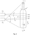
- the products in this case, are bottles as shown in Fig. 4 .
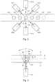
- the product 4.i is provided with an axial axis A which in this example is vertically directed. If a product which has been formed arrives at the position P, a situation as shown in Fig. 2 for the product 4.7 comes about. We assume that in this situation already 17 products have been formed where at some point the seventh formed product 4.7 is at the position P.
- each camera has an aperture angle in a horizontal plane so that an image that is made with a camera covers the whole product in a horizontal direction. This is not requisite, however.
- the aperture angle concerned is indicated with ⁇ .
- the aperture angle ⁇ may for instance also be larger or be smaller than indicated.
- the aperture angle ⁇ (located in a vertical plane) of the camera is such that likewise the whole product 4.7 is covered (see Fig. 4 ).
- the angle ⁇ may also be smaller or be larger than indicated.
- step d. makes the plurality of images in step d. is carried out between the steps b. and c.
- Each image that is made with an infrared camera 10.j is respectively supplied via a line 12.j to the signal processing unit 14. These signals are processed in combination in a step e. for obtaining at least one parameter that depends on a wall thickness of the glass product.
- the sensors applied in step d. are sensitive to infrared light.
- the sensors are sensitive to infrared light having at least one frequency where the glass product is transparent to the infrared light. This has as a consequence that in an image made with an infrared camera both a side 22 of the glass product is visible that faces (is proximal to) the sensor (see Fig. 3 ) and the side 24 located opposite side 22, which faces away (is remote) from the infrared camera 10.j.
- the side 24 is visible to the camera 10.j in Fig. 3 because the camera 10.j also "can see through the side 22".
- Transparent is here understood to mean sufficiently transparent so that an image of the plurality of images both shows a side of the glass product that faces the sensor with which the image has been made and shows a side of the glass product, located opposite the side, that faces away from the sensor with which the image has been made. So the camera can see through the product, but does see the inner and outer surfaces of the product.
- the image obtained with the aid of the camera 10.j covers the whole product in the direction phi (see Fig. 4 ), but it also holds, of course, that the plurality of images in combination cover a first area of the glass product that extends around an axial axis of the product. This first area, in this example, also covers the whole product seen in vertical direction.
- the images thus overlap each other in tangential direction T (see Fig. 4 ) of the product so that different images show a same part of the glass product.
- each camera covers the complete product, both in the axial direction (vertical direction) and in the tangential direction (horizontal direction) of the product.
- the signals from the infrared cameras 10.j that is, the plurality of images which have been made are, according to the principle of tomography, processed in combination for obtaining a lateral glass thickness distribution of the product that is in the first area.
- the first area covers the complete product.
- the processing in combination of the images according to the principle of tomography can be carried out according to a computation technique which is known by the name of "filter back projection", A.R.T. or S.A.R.T.
- the lateral glass distribution LGD has been determined as a function of h and phi.
- the glass distribution LGD (h,phi) can be shown, via a line 16, on the display 18.
- an operator can keep an eye on the glass thickness distribution of the successively produced products 4.i.
- an intervention can be made in the production process, that is, an intervention can be made in the method step b.
- Such an intervention can be performed manually.
- each camera 10.j may also be smaller so that it has a value of for instance y' (see Fig. 4 ).
- a first area 26.1 is covered, the LGD of which is determined with the signal processing unit.
- a second set of cameras 10'.j which are each also provided with an aperture angle y' and which are at a greater height h than the cameras 10.j and whose output signals are also supplied to the signal processing unit (not shown in the drawing)
- a glass thickness distribution of the second area 26.2 which extends around the product can be determined with the signal processing unit (see Fig. 4 ).
- the second area 26.2 is staggered in axial direction with respect to the area 26.1.
- the lateral glass thickness distribution of an area 26.3 is determined.
- the steps d. and e., respectively are carried out repeatedly at least three times for respectively obtaining lateral glass thickness distributions in respectively at least three mutually different areas which each extend around the axial axis and are staggered with respect to each other in axial direction and which preferably in combination cover, at least substantially, the whole glass product.
- the aperture angle in vertical direction is so large that the respective area in which the glass thickness distribution is determined extends throughout the height of the product 4.i in the direction h.
- the aperture angle ⁇ of the cameras 10.j is such that each image shows the product, seen in its horizontal direction b (tangential direction), completely.
- the aperture angle may also be smaller than shown. In that case, on the other hand, the images, seen in horizontal direction, then overlap each other partly so that different images show a same part of the product. This is a minimal condition to be able to make use of the principle of tomography.
- the rotational position R of the glass product around its axial axis on the conveyor is determined. This may for instance be done by detecting where a marking and/or a seam and/or a dot M of the glass product is. The rotational position R may then for instance be an angle R with respect to a centerline 6' of the conveyor 6 (see Fig. 3 ). For when the glass product is manufactured, it may beforehand be provided with a marking such as a dot or a seam. When with the aid of the placing means 5 the glass product is being placed on a conveyor, knowledge about the rotational position of the product is lost because during placement the product can turn about its axial axis.
- the cameras are set up around a position P, with the axial axis of a product to be inspected being also at position P when the recordings are being made. The viewing direction of the camera thus coincides with the point P.
- the cameras are thus preferably set up such that an optical axis 20 (see Fig.
- the infrared cameras are sensitive to light in the spectrum for which the glass is transparent, more particularly that the sensor is sensitive to light having a bandwidth of 900nm - 3500nm, still more particularly that the sensor is sensitive to light having a bandwidth of 900nm - 1900nm.
- a lateral glass thickness distribution is determined according to the steps d. and e., wherein from the determined glass thickness distributions an average glass thickness of the formed glass products is determined and/or wherein from the determined glass thickness distributions a trend in change in glass thickness distributions of successively formed glass products is determined.
- step e for each of the products successively formed in the production flow the rotational position R is determined for comparing in each case the glass thickness distributions or glass thicknesses that relate to a partial area of an area, with the partial areas of the respective products having a same average rotational position.
- a trend can be determined in particular predetermined locations of the products, such as for instance at a particular height h or within a particular range of h and a particular value of phi or within a particular range of phi.
- ray tracing is applied in the processing in combination of the plurality of images according to the principle of tomography for obtaining a lateral glass thickness distribution of the glass that is in the area.
- the glass thickness distribution can comprise absolute values of the glass thickness distribution. It is also possible, however, that the glass thickness distribution indicates only relative variations in glass thickness.
- the invention is not in any way limited to the embodiments outlined above.
- the cameras 10.j have an aperture angle y' while the cameras 10.j, after making the images that are processed in combination for obtaining a glass thickness distribution in the area 26.1, are moved up in axial direction for obtaining six new images in order to obtain a glass thickness distribution in the area 26.2. After this, the cameras may be moved further up for making images of the area 26.3, etc.
- the cameras 10.j and the signal processing unit 14 can also be used in other production processes for forming glass products than described here. In fact, the cameras in combination with the signal processing unit 14 constitute an essential part of the invention.
- the cooling apparatus 7 could be omitted, since also without cooling apparatus 7 the products will eventually cool down as a matter of course so that step c. can also be carried out without extra aids.
- the cooling apparatus may, whether manually or automatically, be controlled (for example, the temperature of the cooling apparatus) on the basis of the determined LGD.
- the infrared camera is a so-called high-speed infrared camera.
- other infrared cameras are also possible.
- a plurality of products are formed parallel to each other.
- the system in this example the product forming apparatus 3, includes six production flow paths 106.k which, for instance, each comprise troughs and a mould.
- the glass gobs which are successively transported along the production flow path 106.k together form a production flow 107.k.
- product 4.1 has been formed from a glass gob which has been transported via production flow path 106.1 in production flow 107.1
- product 4.2 formed from a glass gob which has been transported via production flow path 106.2 in production flow 107.2
- product 4.3 formed from a glass gob which has been transported via production flow path 106.3 in production flow 107.3
- product 4.7 is formed from a glass gob which has been transported via production flow path 106.1 in production flow 107.1
- product 4.8 is formed from a glass gob which has been transported via production flow path 106.2 in production flow 107.2
- product 4.9 is formed from a glass gob which has been transported via production flow path 106.3 in production flow 107.3, etc.
- this process repeats itself.
- the switch 100 for k, successively the value 1,2,3,4,5,6 is chosen by the switch 100.
- the system is configured for carrying out a plurality of the steps b. parallel to each other for producing parallel to each other a plurality of the products in a plurality of production flows which each comprise a step b., wherein the system is further configured for, in use, relating each determined glass thickness distribution of a product to the production flow in which the respective product has been manufactured, more particularly wherein the system is configured for, on the basis of at least one determined glass thickness distribution of a product that has been manufactured in a production flow, controlling that production flow in an automatic manner.
- a production flow can be automatically controlled on the basis of at least one glass thickness distribution of at least one product that has been manufactured in the respective production flow.
- a plurality of the steps b. are carried out parallel to each other for producing parallel to each other a plurality of the products in a plurality of production flows, wherein in each production flow a step b. is carried out, wherein each determined glass thickness distribution of a product is related to the production flow in which the respective product has been manufactured, more particularly wherein on the basis of a glass thickness distribution of a particular product the production flow is controlled (manually or automatically) on the basis of at least one glass thickness distribution of at least one product that has been manufactured in the respective production flow.
- automatic control loops via line 30 can comprise the adjusting (adapting) of:
Landscapes
- Engineering & Computer Science (AREA)
- General Physics & Mathematics (AREA)
- Physics & Mathematics (AREA)
- Chemical & Material Sciences (AREA)
- Manufacturing & Machinery (AREA)
- Organic Chemistry (AREA)
- Materials Engineering (AREA)
- Mechanical Engineering (AREA)
- Theoretical Computer Science (AREA)
- Computer Vision & Pattern Recognition (AREA)
- Quality & Reliability (AREA)
- Life Sciences & Earth Sciences (AREA)
- Pathology (AREA)
- Immunology (AREA)
- General Health & Medical Sciences (AREA)
- Health & Medical Sciences (AREA)
- Biochemistry (AREA)
- Analytical Chemistry (AREA)
- Investigating Materials By The Use Of Optical Means Adapted For Particular Applications (AREA)
- Re-Forming, After-Treatment, Cutting And Transporting Of Glass Products (AREA)
- Investigating Or Analysing Materials By Optical Means (AREA)
- Length Measuring Devices By Optical Means (AREA)
Description
- The invention relates to a method for inspecting hollow glass products of glass product material, wherein the glass products are manufactured by:
- a. heating the glass product material;
- b. forming the heated glass product material into a glass product in a production flow;
- c. cooling the formed glass product;
- d. making a plurality of images of the glass product under a plurality of mutually different viewing directions relative to the product using a plurality of infrared light sensitive sensors, wherein step d. is carried out between steps b. and c.;
- e. processing in combination of the plurality of images for obtaining at least one parameter that depends on a wall thickness of the glass product.
- The invention further relates to a method for producing and inspecting hollow glass products of glass product material, wherein the glass products are manufactured by:
- a. heating the glass product material;
- b. forming the heated glass product material into a glass product in a production flow;
- c. cooling the formed glass product; wherein inspecting the glass products comprises the following steps:
- d. making a plurality of images of the glass product under a plurality of mutually different viewing directions relative to the product using a plurality of infrared light sensitive sensors, wherein step d. is carried out between steps b. and c.;
- e. processing in combination of the plurality of images for obtaining at least one parameter which depends on a wall thickness of the glass product.
- Also, the invention relates to a system for producing and inspecting glass products of glass product material according to the above-mentioned method, wherein the system comprises:
- a heating apparatus for carrying out step a.;
- a product forming apparatus such as a mould for carrying out step b.;
- a cooling apparatus for carrying out step c.;
- the plurality of the sensors for carrying out step d.; and
- a processing unit connected with each of the sensors for processing signals coming from the sensors, the signals each representing an image obtained with one of the sensors, wherein the processing unit is configured for processing in combination of the plurality of images for obtaining at least one parameter which depends on a wall thickness of the glass product.
- In addition, the invention relates to a system for inspecting glass products of glass product material according to the above-mentioned method, wherein the system comprises:
- the plurality of the sensors for carrying out step d.; and
- a signal processing unit connected with each of the sensors for processing signals coming from the sensors, the signals each representing an image obtained with one of the sensors, wherein the processing unit is configured for processing in combination of the plurality of images for obtaining at least one parameter which depends on a wall thickness of the glass product.
- Such methods and systems are known per se, for instance from
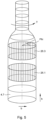
WO-2019133504A1 . In the known method, using a plurality of sensors, images of the still-hot just-manufactured glass products are made. Due to the sensors being set up around the glass product, with the images a full revolution of the product is covered. The making of such a group of images is carried out repeatedly at different points of time. On each of the images, the intensity of the infrared radiation is visible. By comparing two images made at different points of time of a same part of the product, a decrease of the intensity can be established. If the intensity decreases relatively slowly, it is established that the glass material at that spot is relatively thick. If the intensity decreases relatively fast, it is established that the glass material at that spot is relatively thin. In this manner, a lateral glass thickness distribution of the glass product can be determined. A disadvantage is that this method is relatively inaccurate. - This just-mentioned lateral glass thickness distribution, also referred to by the abbreviation LGD (Lateral Glass Distribution), at a particular height is the set of the wall thicknesses around the circumference of the product (
Figure 5 ). This LGD can for instance be obtained by measuring glass wall thicknesses at a particular height h and performing the thickness measurements around the whole circumference of the product. All wall thicknesses of the whole product are the Total Lateral Glass Distribution of the product. A single wall thickness of the product at a defined height h and angle phi (polar coordinates) is an element of the set of wall thicknesses: Lateral Glass Distribution LGD(h,phi). The number of elements in the LGD depends on the, freely to be chosen, measuring resolution of the height and the angle. - The LGD is a very important parameter for the quality of the glass product. The strength of the product is chiefly determined by the thinnest part of a glass wall. In order to prevent breakage in the normal use of the product, the LGD must comply with the specifications of a producer. However, with the current glass production technology, the variation of the Lateral Glass Distribution can range from 35% to 55% of the average glass wall thickness. To arrange for the product to be yet sufficiently strong (minimal reject), this glass thickness variation is compensated for by making the glass wall of extra thick design. As a result, not only does the product become heavier (more glass), but also more base materials are used, it takes more energy to produce the product (melting and annealing) and the transport costs of the glass product become higher due to the extra weight. By minimizing the variation of the lateral glass thickness distribution of the product, the design of the product can be adjusted to have a thinner (more constant) glass wall thickness. The product becomes lighter, the production costs fall proportionally, and so do the transport costs (as well as the CO2, NOx emissions depending thereon).
- To minimize the variation in the lateral glass thickness distribution in the industrial glass forming process, a sensor that is able to determine the LGD in the glass forming process is requisite. Using this sensor, in the production process the root causes of the variation of the LGD can be investigated, for instance by ascertaining which process settings or parts of the process are responsible for an unduly large variation in the LGD. When these causes of the variation of the LGD are known, the responsible process steps can be improved, for instance by optimizing the setting by using the measuring data of the sensor. This may also be done automatically with a feedback system (FeedBack loop) to automate the optimum settings so as to obtain a minimal variation of the LGD. Also, improvements may be incorporated in the responsible process steps, to minimize the variation of the LGD.
- Object of the invention is to improve the known inspection process and possibly, on the basis of the improved inspection process, to improve the production process.
- The method according to the invention is characterised in that the sensors used in step d. are sensitive to infrared light having at least one frequency where the glass product is transparent to the infrared light so that an image of the plurality of images both shows a side of the glass product that faces the sensor with which the image has been made and shows a side of the glass product, located opposite the side, that faces away from the sensor with which the image has been made, wherein the plurality of images cover a first area of the glass product that extends around an axial axis of the product and wherein in step e. the plurality of images are processed in combination according to the principle of tomography for obtaining a lateral glass thickness distribution of the glass that is in the area. Transparent is here understood to mean sufficiently transparent so that an image of the plurality of images both shows a side of the glass product that faces the sensor with which the image has been made and shows a side of the glass product, located opposite the side, that faces away from the sensor with which the image has been made. The camera can hence see through the product, but does see the inner and outer surfaces of the product. It holds that each sensor is sensitive to light in the spectrum to which the glass is transparent, more particularly that the sensor is sensitive to light having a bandwidth of 900nm - 3500nm, still more particularly that the sensor is sensitive to light having a bandwidth of 900nm - 1900nm.
- The invention is based on the insight that in an image, by detection of infrared light to which the hollow glass product is transparent, both a side of the glass product is shown that faces the sensor and a side of the glass product, located opposite the side, that faces away from the sensor.
- On first thoughts, this would seem to be disadvantageous because in that case an image is more difficult to interpret. Because the plurality of images are made, however, it is possible, according to the principle of tomography, to determine information that represents the glass thickness of the material. This information about the glass thickness can then be determined for at least the whole first area that extends around the glass product. With infrared radiation, thus, indirectly the glass thickness is determined. The amount of radiation depends on the temperature (distribution) of the glass and the thickness of the glass (also material properties). In an industrial process the temperature is mostly constant, so that the measurements can be calibrated. The sensor sees a combination of the front glass wall and the rear glass wall. By tomography, this front glass wall and rear glass wall as well as their surfaces can be distinctly detected.
- On the basis of the glass thickness distribution it can be determined whether for instance a glass thickness distribution is within predetermined limits. If this is not the case, for instance the product may be rejected but it is also possible to adjust a parameter of the glass production process, such as for instance the temperature with which the glass product material is heated in step a. or the forming of the heated glass product material into the glass product in step b. In this forming, for instance moulds may be utilized. Adjusting (adapting) step b. may then for instance consist in replacing a mould with a new mould. Also, in step b. troughs may be utilized through which the glass product material flows towards a mould. Such troughs may, for instance upon an established deviation of a glass thickness distribution, be lubricated with a lubricant. Other adjustments (adaptations) are also possible, of course. These adjustments may then be carried out automatically. It is also possible, however, that some adjustments of step b. are carried out manually. In practice, glass products are typically produced parallel to each other in a plurality of moulds. According to the invention, per mould, for products that have been produced with that mould, the glass thickness distributions can then be determined. The glass thickness distributions of products that have been produced with another mould are then determined separately. If one of the moulds exhibits a deviation resulting in a deviation in glass thickness distribution, this can be established separately for that mould on the basis of a glass thickness distribution of a product that has been manufactured in that mould. Also a deviation in at least one trough supplying a glass gob in each case exclusively to one of the moulds, with such deviation resulting in a deviation in the glass thickness distribution of at least one product that has been produced from a glass gob that has flowed through the respective at least one trough, can be detected by detection of a deviation in the associated at least one glass thickness distribution. When deviations in troughs and/or moulds have thus been detected by detection of a deviation in at least one associated glass thickness distribution, these may be corrected, for instance automatically, for instance by readjusting a position and/or orientation of a trough with respect to a mould or providing a trough with a lubricant. Also, a mould may be replaced. It holds, thus, that in particular a plurality of the steps b. are carried out parallel to each other for producing parallel to each other a plurality of the products in a plurality of production flows which each comprise a step b., wherein each determined glass thickness distribution of a product is related to the production flow in which the respective product has been manufactured, more particularly wherein in an automatic manner a production flow is controlled on the basis of at least one glass thickness distribution of at least one product that has been manufactured in the respective product flow. Controlling of a production flow is here understood to mean controlling of hardware with the aid of which the product is manufactured in the production flow. Such controlling can consist in, for instance, setting a position and/or orientation of at least one trough and/or a mould, supplying a lubricant to the at least one trough and/or replacing a mould. In particular, the method is thus characterised in that a plurality of the steps b. are carried out parallel to each other for producing parallel to each other a plurality of the products in a plurality of production flows, wherein in each production flow a step b. is carried out, wherein each determined glass thickness distribution of a product is related to the production flow in which the respective product has been manufactured, more particularly wherein on the basis of a glass thickness distribution of a particular product the production flow is controlled (manually or automatically) on the basis of at least one glass thickness distribution of at least one product which has been manufactured in the respective product flow.
- It holds, preferably, that the glass thickness distribution comprises absolute values of the glass thickness distribution.
- It is also possible, however, that the glass thickness distribution solely indicates relative variations in glass thickness.
- Further, it holds, preferably, that each image of the plurality of images both shows a side of the glass product that faces the at least one sensor with which the image has been made and shows a side of the glass product, located opposite the side, that faces away from the at least one sensor with which the image has been made. In this manner, step e. can be carried out particularly accurately. In particular, it holds, further, that steps d. and e. are carried out repeatedly for obtaining a lateral glass thickness distribution in a second area of the glass product that extends around an axial axis of the product, with the first and second area being staggered with respect to each other in the axial direction.
- The first and second area may partly overlap, adjoin each other, or be apart from each other so that in the latter case between the first and second area is an area that is not covered by the first and second area. Characteristic of these areas is that the glass thickness distribution LGD (h.phi) for the first area can take values of h that cannot be taken in the glass thickness distribution of the second area, since the first and second area are staggered with respect to each other in axial direction. It holds, preferably, that the steps d. and e. are respectively carried out repeatedly at least three times for respectively obtaining lateral glass thickness distributions in respectively at least three mutually different areas which each extend around the axial axis and are staggered with respect to each other in axial direction and which preferably in combination cover, at least substantially, the whole glass product.
- In this way, the glass thickness distribution of the whole product can be mapped. Also, it is possible that the first area covers the whole product.
- The method for producing and inspecting hollow glass products is further characterised in that the sensors used in step d. are sensitive to infrared light having at least one frequency where the glass product is transparent to the infrared light so that an image of the plurality of images both shows a side of the glass product that faces the sensor with which the image has been made and shows a side of the glass product, located opposite the side, that faces away from the sensor with which the image has been made, wherein the plurality of images cover a first area of the glass product that extends around an axial axis of the product and wherein in step e. the plurality of images are processed in combination according to the principle of tomography for obtaining a lateral glass thickness distribution of the glass that is in the area.
- The system for producing and inspecting glass products is further characterised in that the sensors used in step d. are sensitive to infrared light having at least one frequency where the glass product is transparent to the infrared light so that an image of the plurality of images both shows a side of the glass product that faces the sensor with which the image has been made and shows a side of the glass product, located opposite the side, that faces away from the sensor with which the image has been made, wherein the plurality of images cover a first area of the glass product that extends around an axial axis of the product and wherein the processing unit is further configured for carrying out step e. of the method according to the characterising portion of
claim 1. - The system for inspecting glass products is further characterised in that the sensors used in step d. are sensitive to infrared light having at least one frequency where the glass product is transparent to the infrared light so that an image of the plurality of images both shows a side of the glass product that faces the sensor with which the image has been made and shows a side of the glass product, located opposite the side, that faces away from the sensor with which the image has been made, wherein the plurality of images cover a first area of the glass product that extends around an axial axis of the product and wherein the processing unit is further configured for carrying out step e. of the method according to the characterising portion of
claim 1. - The invention will now be further explained on the basis of the drawing. In the drawing:
-
Figure 1 shows a possible embodiment of a system according to the invention for carrying out a method according to the invention; -
Figure 2 shows the use of a part of the system ofFigure 1 ; -
Figure 3 shows a part of the use according toFigure 2 ; -
Figure 4 shows a possible implementation of the glass product that is manufactured in the system ofFigure 1 ; -
Figure 5 shows schematically a 3D view of a glass product in which areas are hatched of which an LGD has been determined; and -
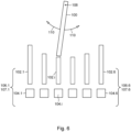
Figure 6 shows schematically a top plan view of a possible embodiment of the product forming apparatus ofFigure 1 . - In
Figure 1 with reference numeral 1 a system according to the invention is indicated for carrying out a method according to the invention. The system comprises a schematically shownheating apparatus 2 for heating glass product material so that the glass product material enters a molten state. The molten material is transported to aproduct forming apparatus 3. In addition, other materials may be supplied to theproduct forming apparatus 3 if this is necessary, such as other materials and/or semimanufactures. In this embodiment, theproduct forming apparatus 3 manufactures in each case one hollow glass product 4.i (i=1,2,3,...) in a production flow. The glass product 4.i is here manufactured after the glass product 4.i-1. Theproduct forming apparatus 3 in this example includes for this purpose one mould, known per se, 104 (shown schematically inFig. 1 ) into which a portion of the heated glass product material is introduced, and at least one trough 102 (shown schematically inFig. 1 ) to guide a glass gob to the mould. Also, theproduct forming apparatus 3 comprises blowing means (not shown) for blowing or pushing the glass product material into the mould for obtaining the final shape of the glass product. While in this example the product forming apparatus comprises one mould, it is, of course, also possible that the product forming apparatus comprises a plurality of moulds for manufacturing parallel to each other a plurality of products in a plurality of parallel production flows. An example of this will, after the discussion of the variant with one mould, be discussed as well, with reference to a variant with six moulds. - The successively formed glass products 4.i are placed with the aid of a
placing unit 5 on aconveyor 6. - The glass products 4.i produced as described above are transported with the aid of the
conveyor 6 to a position P where inspection of a glass product can take place as will be set out hereinafter. Using the conveyor, the products are then transported further to a cooling apparatus for cooling of the glass product. With thearrow 8, the direction of transport of the conveyor is indicated. - Arranged around the position P, in this example, are six infrared cameras 10.j (j=1,2,3,...,6). The infrared cameras 10.j are herein also referred to as sensors 10.j.
- Via lines 12.j which are respectively connected with the infrared cameras 10.j, signals of the infrared cameras are supplied to a
signal processing unit 14. Thesignal processing unit 14 is connected via aline 16 with adisplay 18. - The working of the system according to the invention is as follows. In a step a., glass product material is heated with the
heating unit 2. Then, in a step b., the heated and molten 'liquid' glass material is formed into a glass product. The glass products thus successively formed are placed with the aid of theplacing unit 5 on theconveyor 6 for transport in thedirection 8. The products, in this case, are bottles as shown inFig. 4 . The product 4.i is provided with an axial axis A which in this example is vertically directed. If a product which has been formed arrives at the position P, a situation as shown inFig. 2 for the product 4.7 comes about. We assume that in this situation already 17 products have been formed where at some point the seventh formed product 4.7 is at the position P. Using the cameras 10.j a plurality of images of the glass product 4.7 are made under a plurality of mutuallydifferent viewing directions 20 relative to the product 4.7. Theviewing directions 20 in this example are indicated witharrows 20. In this example, each camera has an aperture angle in a horizontal plane so that an image that is made with a camera covers the whole product in a horizontal direction. This is not requisite, however. InFig. 3 the aperture angle concerned is indicated with α. However, the aperture angle α may for instance also be larger or be smaller than indicated. Viewed in vertical direction, the aperture angle γ (located in a vertical plane) of the camera is such that likewise the whole product 4.7 is covered (seeFig. 4 ). However, the angle γ may also be smaller or be larger than indicated. - It will be clear that making the plurality of images in step d. is carried out between the steps b. and c.
- Each image that is made with an infrared camera 10.j is respectively supplied via a line 12.j to the
signal processing unit 14. These signals are processed in combination in a step e. for obtaining at least one parameter that depends on a wall thickness of the glass product. - As mentioned, the sensors applied in step d. are sensitive to infrared light. In particular, the sensors are sensitive to infrared light having at least one frequency where the glass product is transparent to the infrared light. This has as a consequence that in an image made with an infrared camera both a
side 22 of the glass product is visible that faces (is proximal to) the sensor (seeFig. 3 ) and theside 24 locatedopposite side 22, which faces away (is remote) from the infrared camera 10.j. For theside 24 is visible to the camera 10.j inFig. 3 because the camera 10.j also "can see through theside 22". Transparent is here understood to mean sufficiently transparent so that an image of the plurality of images both shows a side of the glass product that faces the sensor with which the image has been made and shows a side of the glass product, located opposite the side, that faces away from the sensor with which the image has been made. So the camera can see through the product, but does see the inner and outer surfaces of the product. - Having regard to the aperture angle α, the image obtained with the aid of the camera 10.j covers the whole product in the direction phi (see
Fig. 4 ), but it also holds, of course, that the plurality of images in combination cover a first area of the glass product that extends around an axial axis of the product. This first area, in this example, also covers the whole product seen in vertical direction. The images thus overlap each other in tangential direction T (seeFig. 4 ) of the product so that different images show a same part of the glass product. In this case, each camera covers the complete product, both in the axial direction (vertical direction) and in the tangential direction (horizontal direction) of the product. According to the invention, the signals from the infrared cameras 10.j, that is, the plurality of images which have been made are, according to the principle of tomography, processed in combination for obtaining a lateral glass thickness distribution of the product that is in the first area. In this case, the first area covers the complete product. The processing in combination of the images according to the principle of tomography can be carried out according to a computation technique which is known by the name of "filter back projection", A.R.T. or S.A.R.T. In this way, the lateral glass distribution LGD has been determined as a function of h and phi. The glass distribution LGD (h,phi) can be shown, via aline 16, on thedisplay 18. In this way, an operator can keep an eye on the glass thickness distribution of the successively produced products 4.i. When the glass thickness distribution starts to deviate, for instance because the wall thickness of the product is becoming too large or too small at certain points, an intervention can be made in the production process, that is, an intervention can be made in the method step b. Such an intervention can be performed manually. However, it is also possible for such an intervention to be performed automatically, in this case via afeedback control line 30. All this is schematically indicated inFig. 1 . - It is noted that the aperture angle y of each camera 10.j may also be smaller so that it has a value of for instance y' (see
Fig. 4 ). In that case, with the cameras 10.j a first area 26.1 is covered, the LGD of which is determined with the signal processing unit. In that case, using a second set of cameras 10'.j which are each also provided with an aperture angle y' and which are at a greater height h than the cameras 10.j and whose output signals are also supplied to the signal processing unit (not shown in the drawing), a glass thickness distribution of the second area 26.2 which extends around the product can be determined with the signal processing unit (seeFig. 4 ). The second area 26.2 is staggered in axial direction with respect to the area 26.1. Also, entirely analogously, it is possible that with the aid of a third set of six cameras (not shown) the lateral glass thickness distribution of an area 26.3 is determined. The areas 26.1, 26.2 and 26.3, for instance, adjoin each other then. It holds thus for the areas 26.1 and 26.2 that steps d. and e. are carried out repeatedly for obtaining a lateral glass distribution LGD in a second area of the glass product that extends around an axial axis of the product, with the first and second area being staggered with respect to each other in the axial direction. - In particular, it holds for the areas 26.1 to 26.3 that the steps d. and e., respectively, are carried out repeatedly at least three times for respectively obtaining lateral glass thickness distributions in respectively at least three mutually different areas which each extend around the axial axis and are staggered with respect to each other in axial direction and which preferably in combination cover, at least substantially, the whole glass product.
- It holds preferably, however, that the aperture angle in vertical direction is so large that the respective area in which the glass thickness distribution is determined extends throughout the height of the product 4.i in the direction h. Further, it holds in this example that the aperture angle α of the cameras 10.j is such that each image shows the product, seen in its horizontal direction b (tangential direction), completely. However, the aperture angle may also be smaller than shown. In that case, on the other hand, the images, seen in horizontal direction, then overlap each other partly so that different images show a same part of the product. This is a minimal condition to be able to make use of the principle of tomography.
- Further, it holds in this example that with the aid of the
signal processing unit 14, from the images that are made with the cameras the rotational position R of the glass product around its axial axis on the conveyor is determined. This may for instance be done by detecting where a marking and/or a seam and/or a dot M of the glass product is. The rotational position R may then for instance be an angle R with respect to a centerline 6' of the conveyor 6 (seeFig. 3 ). For when the glass product is manufactured, it may beforehand be provided with a marking such as a dot or a seam. When with the aid of the placing means 5 the glass product is being placed on a conveyor, knowledge about the rotational position of the product is lost because during placement the product can turn about its axial axis. This has as a consequence that when a deviation is found in the glass thickness of the product, it may be disadvantageous when it is not known where this deviation is with respect to the marking. When it is known, it can, in certain instances, be determined better where in the product forming apparatus the problem of the deviation is caused. That is why preferably also the rotational position of the glass product around its axial axis is determined. Preferably, it holds that the cameras are set up around a position P, with the axial axis of a product to be inspected being also at position P when the recordings are being made. The viewing direction of the camera thus coincides with the point P. The cameras are thus preferably set up such that an optical axis 20 (seeFig. 3 ) of the sensors, at least substantially, crosses the axial axis of the glass product so that, in particular, in step e.'s processing in combination of the plurality of images according to the principle of tomography for obtaining the lateral glass distribution of the glass which is at least in the first area, per sensor only IR light is used that, relative to a respective sensor, comes substantially from the direction of the axial axis of the glass product. InFigure 1 two more cameras may be additionally placed at positions higher than an upper side of the glass products on the conveyingplant 6 and above the conveying plant and with their optical axes directed obliquely down to the position P. The cameras are then on both sides of the position P so that, seen from above, all cameras are set up regularly distributed along a fictitious circle. - In this example, it holds that the infrared cameras are sensitive to light in the spectrum for which the glass is transparent, more particularly that the sensor is sensitive to light having a bandwidth of 900nm - 3500nm, still more particularly that the sensor is sensitive to light having a bandwidth of 900nm - 1900nm.
- In particular, it holds that, of a plurality of glass products successively formed in the production flow, per glass product a lateral glass thickness distribution is determined according to the steps d. and e., wherein from the determined glass thickness distributions an average glass thickness of the formed glass products is determined and/or wherein from the determined glass thickness distributions a trend in change in glass thickness distributions of successively formed glass products is determined.
- If a trend is determined, it may for instance be inferred that a particular part, such as a mould, is wearing. Further, it holds in particular that in step e. for each of the products successively formed in the production flow the rotational position R is determined for comparing in each case the glass thickness distributions or glass thicknesses that relate to a partial area of an area, with the partial areas of the respective products having a same average rotational position.
- In this way, for instance, a trend can be determined in particular predetermined locations of the products, such as for instance at a particular height h or within a particular range of h and a particular value of phi or within a particular range of phi. In particular, it holds furthermore that in the processing in combination of the plurality of images according to the principle of tomography for obtaining a lateral glass thickness distribution of the glass that is in the area, ray tracing is applied.
- It is noted that the glass thickness distribution can comprise absolute values of the glass thickness distribution. It is also possible, however, that the glass thickness distribution indicates only relative variations in glass thickness.
- The invention is not in any way limited to the embodiments outlined above. For instance, it is also possible that the cameras 10.j have an aperture angle y' while the cameras 10.j, after making the images that are processed in combination for obtaining a glass thickness distribution in the area 26.1, are moved up in axial direction for obtaining six new images in order to obtain a glass thickness distribution in the area 26.2. After this, the cameras may be moved further up for making images of the area 26.3, etc. Further, it is clear that the cameras 10.j and the
signal processing unit 14 can also be used in other production processes for forming glass products than described here. In fact, the cameras in combination with thesignal processing unit 14 constitute an essential part of the invention. According to the invention, also, thecooling apparatus 7 could be omitted, since also without coolingapparatus 7 the products will eventually cool down as a matter of course so that step c. can also be carried out without extra aids. Also, the cooling apparatus may, whether manually or automatically, be controlled (for example, the temperature of the cooling apparatus) on the basis of the determined LGD. - In particular, it holds that the infrared camera is a so-called high-speed infrared camera. However, other infrared cameras are also possible.
- According to an alternative embodiment, a plurality of products are formed parallel to each other. In the example of
Figure 6 , six products are formed parallel to each other. To this end, the system, in this example theproduct forming apparatus 3, includes six production flow paths 106.k which, for instance, each comprise troughs and a mould. This is shown inFigure 6 in which a formed glass gob is guided via aswitch 100 to a production flow path 106.k (k=1,2,3,..6) selected with the switch, each production flow path 106.k comprising a number of troughs 102.k and a mould 104.k. The glass gobs which are successively transported along the production flow path 106.k together form a production flow 107.k. By rotation of the switch in the direction ofarrows 110 around an axis (pivot) 108, other production flow paths 106.k can be selected with the switch. The glass gob flows, in this example, via the selected at least one trough 102.k to the mould 104.k. In this example, for k, successively thevalues switch 100. In this example, there are thus six parallel production flows. - Because there are six production flows, in succession six products 4.1, 4.2, 4.3, ...4.6 are formed which are placed in a row of six products on the conveyor. Here, product 4.1 has been formed from a glass gob which has been transported via production flow path 106.1 in production flow 107.1, product 4.2 formed from a glass gob which has been transported via production flow path 106.2 in production flow 107.2, product 4.3 formed from a glass gob which has been transported via production flow path 106.3 in production flow 107.3, etc. More generally, product 4.j has been formed from a glass gob which has been transported via production flow path 106.k in production flow 107.k, for k = 1,2,3,4,5,6. When thus six products have been produced, this process repeats itself.
- Here, product 4.7 is formed from a glass gob which has been transported via production flow path 106.1 in production flow 107.1, product 4.8 is formed from a glass gob which has been transported via production flow path 106.2 in production flow 107.2, product 4.9 is formed from a glass gob which has been transported via production flow path 106.3 in production flow 107.3, etc. More generally, product 4.k+6 has been formed from a glass gob which has been transported via production flow path 106.k in production flow 107.k, for k = 1,2,3,4,5,6. When thus six products have been produced, this process repeats itself. Generally, therefore, it holds that product 4.k+n.6 with n=0,1,2,3,.... has been formed from a glass gob which has been transported via production flow path 106.k in production flow 107.k for k = 1,2,3,4,5,6.
- In this example, for k, successively the
value switch 100. The system is configured to determine the glass thickness distribution per product with the signal processing unit. Each determined glass thickness distribution of a product 4.i=k, 4.i=k+6, 4.i=k+12, etc., can be related by the signal processing unit to an associated production flow 107.k. If, for instance, in a product 4.i=k+18 a deviation in the associated glass distribution is established, the system (in this case the signal processing unit) is configured to relate this to the production flow path 106.k (and hence to the production flow 107.k) with which the respective product has been manufactured. This holds in general for a deviation in the glass distribution of product 4.i=k+n.6 with n=0 or 1 or 2 or 3 or ...etc. Thus, in the case of such deviation, for instance in an automatic manner the position and/or orientation of the at least one trough 102.k and/or the mould 104.k of the production flow path 106.k with which the respective product has been manufactured can be readjusted and/or the at least one trough 102.k of the production flow path 106.k in which the respective product has been manufactured may be provided with a lubricant. Also, it is possible that the respective mould 104.k is replaced. - It holds thus that the system is configured for carrying out a plurality of the steps b. parallel to each other for producing parallel to each other a plurality of the products in a plurality of production flows which each comprise a step b., wherein the system is further configured for, in use, relating each determined glass thickness distribution of a product to the production flow in which the respective product has been manufactured, more particularly wherein the system is configured for, on the basis of at least one determined glass thickness distribution of a product that has been manufactured in a production flow, controlling that production flow in an automatic manner. To put it differently, a production flow can be automatically controlled on the basis of at least one glass thickness distribution of at least one product that has been manufactured in the respective production flow. It holds thus for the method in particular that a plurality of the steps b. are carried out parallel to each other for producing parallel to each other a plurality of the products in a plurality of production flows, wherein in each production flow a step b. is carried out, wherein each determined glass thickness distribution of a product is related to the production flow in which the respective product has been manufactured, more particularly wherein on the basis of a glass thickness distribution of a particular product the production flow is controlled (manually or automatically) on the basis of at least one glass thickness distribution of at least one product that has been manufactured in the respective production flow.
- Finally, it is noted that automatic control loops via
line 30 can comprise the adjusting (adapting) of: - Feeder temperature and temperature distribution
- Gob temperature distribution
- Gob forming process
- Gob loading process
- Mould cooling and residence time in the mould
- Design of the parison and the preform moulds
- Blowout process (B&B process)
- Plunger press process (NNPB, PB process)
- Plunger cooling process
- Blowout process at the front
- Shape and design of the blowing pipe
- Optimal lubricating method and lubricant moulds
- Optimal standing time determination of the moulds
- Optimal timing setting of the I.S. machine (glass forming machine)
- Optimal temperature settings of moulds and automatic control thereof
- Optimal air pressure control of product blowout
- Optimal air pressure control for making the parison
- Active reheating for an optimal temperature distribution of the glass gobs for an optimal LGD
Claims (16)
- Method for inspecting hollow glass products (4) of glass product material, wherein the glass products are manufactured by:a. heating the glass product material;b. forming the heated glass product material into a glass product in a production flow;c. cooling the formed glass product;wherein inspecting the glass products comprises the following steps:d. making a plurality of images of the glass product under a plurality of mutually different viewing directions (20) relative to the product using a plurality of infrared light sensitive sensors (10), wherein step d. is carried out between steps b. and c.;e. processing in combination of the plurality of images of the glass product for obtaining at least one parameter that depends on a wall thickness of the glass product, characterised in that the sensors used in step d. are sensitive to infrared light having at least one frequency where the glass product is transparent to the infrared light so that an image of the plurality of images both shows a side (22) of the glass product that faces the sensor with which the image has been made and shows a side (24) of the glass product, located opposite said side, that faces away from the sensor with which the image has been made, wherein the plurality of images in combination cover at least a first area (26.1) of the glass product that extends around an axial axis (A) of the product, wherein the images seen in tangential direction (T) of the product overlap each other so that different images show a same part of the glass product, and wherein in step e. the plurality of images are processed in combination according to the principle of tomography for obtaining a lateral glass thickness distribution of the glass that is at least in the first area.
- Method according to claim 1, characterised in that the glass thickness distribution indicates solely relative variations in glass thickness, or characterised in that the glass thickness distribution comprises absolute values of the glass thickness distribution.
- Method according to any one of the preceding claims, characterised in that for calibrating step e. the steps d. and e. are carried out on a glass product having a known glass thickness distribution.
- Method according to any one of the preceding claims, characterised in that each image of the plurality of images both shows a side of the glass product that faces the sensor with which the image has been made and shows a side of the glass product, located opposite said side, that faces away from the sensor with which the image has been made.
- Method according to any one of the preceding claims, characterised in that the sensors are each set up such that a first optical axis of the sensors at least substantially crosses the axial axis of the glass product so that in particular in step e.'s processing in combination of the plurality of images according to the principle of tomography for obtaining the lateral glass thickness distribution of the glass that is at least in the first area, per sensor only infrared light is used that, relative to a respective sensor, substantially comes from the direction (h) of the axial axis of the glass product.
- Method according to any one of the preceding claims, characterised in that the processing in combination according to the principle of tomography comprises a computation technique according to (Filtered) Back Projection, A.R.T or S.A.R.T; wherein optionally the first area viewed in a direction (b) of the axial axis of the glass product covers the glass product at least substantially wholly.
- Method according to any one of the preceding claims, characterised in that steps d. and e. are carried out repeatedly for obtaining a lateral glass thickness distribution in a second area (26.2) of the glass product that extends around the axial axis of the product, wherein the first and second area are staggered with respect to each other in the axial direction, wherein optionally the steps d. and e. are respectively carried out repeatedly at least three times for respectively obtaining lateral glass thickness distributions in respectively at least three mutually different areas (26.1, 26.2, 26.3) that each extend around the axial axis and are staggered with respect to each other in axial direction and which preferably in combination cover at least substantially the whole glass product.
- Method according to any one of the preceding claims, characterised in that the axial axis is at least substantially vertically directed.
- Method according to any one of the preceding claims, characterised in that the glass product between steps b. and c. is transported on a conveyor (6); wherein optionally the glass product between steps b. and c. is transported on the conveyor from a product forming apparatus (3) such as a mould (104) in which the glass product has been formed in step b. to a cooling apparatus in which the product is cooled in step c; , and/or optionally characterised in that the rotational position (R) of the glass product around its axial axis on the conveyor is determined, wherein optionally i) the rotational position is determined with the aid of at least one of the sensors by recognizing a predetermined marking on or in the glass product, wherein further optionally the marking is a seam and/or a dot (M), and/or wherein optionally ii) inspecting also comprises a controlling whereby at least one step of the steps a., b. and c. is adjusted on the basis of at least one determined glass thickness distribution and associated determined rotational position, and/or wherein optionally iii) in step e. for each of the products successively formed in the production flow, the rotational position is determined for comparing in each case the glass thickness distributions or glass thicknesses that relate to a partial area of an area, wherein the partial areas of the respective products have a same average rotational position.
- Method according to any one of the preceding claims, characterised in that the sensors are set up around a common position (P) and lie at least substantially in a common horizontal plane; wherein optionally the glass product to be inspected is at the position (P) when with the sensors recordings of the glass product are made,, wherein further optionally, when dependent on claim 7 the sensors are displaced in the axial direction for obtaining recordings in the different areas.
- Method according to any one of the preceding claims, characterised in that each sensor comprises an IR camera, in particular a high-speed IR camera; and/or characterised in that each sensor is sensitive to light in the spectrum for which the glass product is transparent, more particularly that each sensor is sensitive to light having a bandwidth of 900nm - 3500nm, still more particularly that each sensor is sensitive to light having a bandwidth of 900nm - 1900nm; and/or characterised in that, of a plurality of glass products successively formed in the production flow, per glass product a lateral glass thickness distribution is determined according to the steps d. and e., wherein from the determined glass thickness distributions an average glass thickness of the formed glass products is determined and/or wherein from the determined glass thickness distributions a trend in change in glass thickness distributions of successively formed glass products is determined, and/or characterised in that in the processing in combination of the plurality of images according to the principle of tomography for obtaining a lateral glass thickness distribution of the glass that is in the area, ray tracing is used, and/or characterised in that a plurality of the steps b. are carried out parallel to each other for producing parallel to each other a plurality of the products in a plurality of production flows, wherein in each production flow a step b. is carried out, wherein each determined glass thickness distribution of a product is related to the production flow in which the respective product has been manufactured.
- Method for producing and inspecting hollow glass products (4) of glass product material, wherein the glass products are manufactured and inspected using the steps of claim 1.
- Method according to claim 12, further characterised by one of claims 2-11, wherein optionally a plurality of the steps b. are carried out parallel to each other for producing parallel to each other a plurality of the products in a plurality of production flows, wherein in each production flow a step b. is carried out, wherein each determined glass thickness distribution of a product is related to the production flow in which the respective product has been manufactured, more particularly wherein on the basis of a glass thickness distribution of a particular product the production flow is controlled on the basis of at least one glass thickness distribution of at least one product that has been manufactured in the respective production flow.
- System (1) for inspecting glass products (4) of glass product material according to the method according to the pre-characterising portion of claim 1, wherein the system comprises:the plurality of the sensors (10) for carrying out step d.; anda signal processing unit (14) connected with each of the sensors for processing signals coming from the sensors, the signals each representing an image obtained with one of the sensors, wherein the processing unit is configured for processing in combination of the plurality of images for obtaining at least one parameter that depends on a wall thickness of the glass product, characterised in that the sensors used in step d. are sensitive to infrared light having at least one frequency where the glass product is transparent to the infrared light so that an image of the plurality of images both shows a side (22) of the glass product that faces the sensor with which the image has been made and shows a side (24) of the glass product, located opposite said side, that faces away from the sensor with which the image has been made, wherein the plurality of images cover a first area (26.1) of the glass product that extends around an axial axis (A) of the product, and that the processing unit is further configured for carrying out step e. of the method according to the characterising portion of claim 1.
- System (1) according to claim 14, wherein the system further at least comprises:a heating apparatus (2) for carrying out step a.;a product forming apparatus (3) such as a mould (104) for carrying out step b.;a cooling apparatus for carrying out step c., wherein optionally a) the system is further configured for carrying out the method according to any one of the claims 2-11, and/or wherein optionally b) the system further comprises a conveyor for carrying out the method according to at least claim 9 of the claims 2-11; and/or wherein optionally the system is configured for, on the basis of the determined glass thickness distribution, in an automatic manner, setting parameters of the heating apparatus, the product forming apparatus and/or the cooling apparatus.
- System according to any one of claims 14-15, characterised in that the system is configured for carrying out a plurality of the steps b. parallel to each other for producing parallel to each other a plurality of the products in a plurality of production flows which each comprise a step b., wherein the system is further configured for, in use, relating each determined glass thickness distribution of a product to the production flow in which the respective product has been manufactured, more particularly wherein the system is configured for, on the basis of a glass thickness distribution of a particular product, in an automatic manner, controlling the production flow on the basis of at least one glass thickness distribution of at least one product that has been manufactured in the respective production flow.
Applications Claiming Priority (2)
| Application Number | Priority Date | Filing Date | Title |
|---|---|---|---|
| NL2026864A NL2026864B1 (en) | 2020-11-11 | 2020-11-11 | a method for inspecting hollow glass products of glass product material. |
| PCT/NL2021/050696 WO2022103265A1 (en) | 2020-11-11 | 2021-11-11 | A method for inspecting hollow glass products of glass product material |
Publications (2)
| Publication Number | Publication Date |
|---|---|
| EP4244575A1 EP4244575A1 (en) | 2023-09-20 |
| EP4244575B1 true EP4244575B1 (en) | 2024-12-18 |
Family
ID=74195061
Family Applications (1)
| Application Number | Title | Priority Date | Filing Date |
|---|---|---|---|
| EP21806425.1A Active EP4244575B1 (en) | 2020-11-11 | 2021-11-11 | Method for inspecting hollow glass products of glass product material |
Country Status (4)
| Country | Link |
|---|---|
| US (1) | US12482087B2 (en) |
| EP (1) | EP4244575B1 (en) |
| NL (1) | NL2026864B1 (en) |
| WO (1) | WO2022103265A1 (en) |
Citations (6)
| Publication number | Priority date | Publication date | Assignee | Title |
|---|---|---|---|---|
| EP0643297A1 (en) | 1993-09-09 | 1995-03-15 | TCE CONSULTANCY & ENGINEERING | Analytical system for analyzing, monitoring, diagnosing and/or controlling a process for manufacturing packaging glass products in which the analysis takes place directly after the glass-shaping process |
| EP1020703B1 (en) | 1999-01-12 | 2009-03-11 | Owens-Brockway Glass Container Inc. | Measurement of hot glass container wall thickness |
| WO2010063935A1 (en) | 2008-12-03 | 2010-06-10 | Iris - Inspection Machines | Machine for inspecting defects in a transparent or translucent object |
| US20110141265A1 (en) | 2009-12-10 | 2011-06-16 | Mark Edwin Holtkamp | System and Method for Monitoring Hot Glass Containers to Enhance Their Quality and Control the Forming Process |
| DE102019005487B3 (en) | 2019-08-06 | 2020-07-09 | Heye International Gmbh | Method for measuring the wall thickness of a hollow glass article |
| WO2021009456A1 (en) * | 2019-07-12 | 2021-01-21 | Tiama | Equipment and method for measuring the thickness of the walls of glass containers |
Family Cites Families (7)
| Publication number | Priority date | Publication date | Assignee | Title |
|---|---|---|---|---|
| FR2939133B1 (en) | 2008-12-03 | 2011-04-15 | Oreal | NOVEL AMINO C-XYLOSIDE COMPOUNDS AND USE IN COSMETICS |
| FR2988946A1 (en) | 2012-03-27 | 2013-10-04 | France Telecom | METHOD FOR SELECTING A BROADCAST MODE |
| FR2988846B1 (en) * | 2012-03-27 | 2014-04-11 | Msc & Sgcc | METHOD AND INSTALLATION FOR MEASURING THE DISTRIBUTION OF GLASS IN CONTAINERS |
| NL2009980C2 (en) * | 2012-12-13 | 2014-06-16 | Ct Voor Tech Informatica B V | A method of producing glass products from glass product material and an assembly for performing said method. |
| EP3239697A1 (en) * | 2016-04-28 | 2017-11-01 | Stratec Control-Systems GmbH | Method and device for detecting foreign matter in containers |
| FR3074907B1 (en) * | 2017-12-08 | 2019-12-27 | Tiama | METHOD AND MACHINE FOR CONTROLLING A FORMING PROCESS |
| US10495445B2 (en) * | 2017-12-27 | 2019-12-03 | Applied Vision Corporation | Glass container inspection system |
-
2020
- 2020-11-11 NL NL2026864A patent/NL2026864B1/en active
-
2021
- 2021-11-11 WO PCT/NL2021/050696 patent/WO2022103265A1/en not_active Ceased
- 2021-11-11 US US18/252,403 patent/US12482087B2/en active Active
- 2021-11-11 EP EP21806425.1A patent/EP4244575B1/en active Active
Patent Citations (6)
| Publication number | Priority date | Publication date | Assignee | Title |
|---|---|---|---|---|
| EP0643297A1 (en) | 1993-09-09 | 1995-03-15 | TCE CONSULTANCY & ENGINEERING | Analytical system for analyzing, monitoring, diagnosing and/or controlling a process for manufacturing packaging glass products in which the analysis takes place directly after the glass-shaping process |
| EP1020703B1 (en) | 1999-01-12 | 2009-03-11 | Owens-Brockway Glass Container Inc. | Measurement of hot glass container wall thickness |
| WO2010063935A1 (en) | 2008-12-03 | 2010-06-10 | Iris - Inspection Machines | Machine for inspecting defects in a transparent or translucent object |
| US20110141265A1 (en) | 2009-12-10 | 2011-06-16 | Mark Edwin Holtkamp | System and Method for Monitoring Hot Glass Containers to Enhance Their Quality and Control the Forming Process |
| WO2021009456A1 (en) * | 2019-07-12 | 2021-01-21 | Tiama | Equipment and method for measuring the thickness of the walls of glass containers |
| DE102019005487B3 (en) | 2019-08-06 | 2020-07-09 | Heye International Gmbh | Method for measuring the wall thickness of a hollow glass article |
Non-Patent Citations (5)
Also Published As
| Publication number | Publication date |
|---|---|
| US20240029231A1 (en) | 2024-01-25 |
| NL2026864B1 (en) | 2022-06-28 |
| EP4244575A1 (en) | 2023-09-20 |
| WO2022103265A1 (en) | 2022-05-19 |
| US12482087B2 (en) | 2025-11-25 |
Similar Documents
| Publication | Publication Date | Title |
|---|---|---|
| EP1418158B1 (en) | Glass gob quality control method and quality control device in glass article molding method | |
| EP0643297B1 (en) | Analytical system for analyzing, monitoring, diagnosing and/or controlling a process for manufacturing packaging glass products in which the analysis takes place directly after the glass-shaping process | |
| US6620352B1 (en) | Automated material distribution control for stretch blow molded articles | |
| EP1525469B1 (en) | Analytical system and method for measuring and controlling a production process | |
| EP2336740A1 (en) | Method and system for monitoring and controlling a glass container forming process | |
| CN114126832B (en) | Device for optical inspection of preforms | |
| WO1997004887A1 (en) | Hot bottle inspection apparatus and method | |
| US6025910A (en) | Object inspection method utilizing a corrected image to find unknown characteristic | |
| US5734467A (en) | Inspection apparatus for high temperature environments | |
| JP2022541750A (en) | Apparatus and method for measuring wall thickness of multiple glass containers | |
| EP4244575B1 (en) | Method for inspecting hollow glass products of glass product material | |
| DE102012002016B4 (en) | Method for controlling the process parameters of a glass forming machine and use of the method | |
| US20210041233A1 (en) | Method for Measuring the Wall Thickness of a Hollow Glass Article | |
| EP4244576B1 (en) | Method for inspecting hollow glass products of glass product material | |
| JP5854757B2 (en) | Single crystal ingot diameter control method | |
| NL2028215B1 (en) | Method of inspecting hollow glass products of glass product material | |
| US20250340476A1 (en) | System for monitoring and regulating sections of a machine for forming hollow glass articles and method for monitoring and regulating sections of such a machine | |
| WO2020201759A1 (en) | Temperature mapping apparatus and method | |
| FR3134806A3 (en) | System for controlling and regulating the sections of a machine for forming hollow glass articles and Method for controlling and regulating the sections of such a machine. | |
| FR3134387A1 (en) | System for controlling and regulating the sections of a machine for forming hollow glass articles and Method for controlling and regulating the sections of such a machine. |
Legal Events
| Date | Code | Title | Description |
|---|---|---|---|
| STAA | Information on the status of an ep patent application or granted ep patent |
Free format text: STATUS: UNKNOWN |
|
| STAA | Information on the status of an ep patent application or granted ep patent |
Free format text: STATUS: THE INTERNATIONAL PUBLICATION HAS BEEN MADE |
|
| PUAI | Public reference made under article 153(3) epc to a published international application that has entered the european phase |
Free format text: ORIGINAL CODE: 0009012 |
|
| STAA | Information on the status of an ep patent application or granted ep patent |
Free format text: STATUS: REQUEST FOR EXAMINATION WAS MADE |
|
| 17P | Request for examination filed |
Effective date: 20230609 |
|
| AK | Designated contracting states |
Kind code of ref document: A1 Designated state(s): AL AT BE BG CH CY CZ DE DK EE ES FI FR GB GR HR HU IE IS IT LI LT LU LV MC MK MT NL NO PL PT RO RS SE SI SK SM TR |
|
| DAV | Request for validation of the european patent (deleted) | ||
| DAX | Request for extension of the european patent (deleted) | ||
| GRAP | Despatch of communication of intention to grant a patent |
Free format text: ORIGINAL CODE: EPIDOSNIGR1 |
|
| STAA | Information on the status of an ep patent application or granted ep patent |
Free format text: STATUS: GRANT OF PATENT IS INTENDED |
|
| INTG | Intention to grant announced |
Effective date: 20240711 |
|
| GRAS | Grant fee paid |
Free format text: ORIGINAL CODE: EPIDOSNIGR3 |
|
| GRAA | (expected) grant |
Free format text: ORIGINAL CODE: 0009210 |
|
| STAA | Information on the status of an ep patent application or granted ep patent |
Free format text: STATUS: THE PATENT HAS BEEN GRANTED |
|
| AK | Designated contracting states |
Kind code of ref document: B1 Designated state(s): AL AT BE BG CH CY CZ DE DK EE ES FI FR GB GR HR HU IE IS IT LI LT LU LV MC MK MT NL NO PL PT RO RS SE SI SK SM TR |
|
| REG | Reference to a national code |
Ref country code: CH Ref legal event code: EP |
|
| REG | Reference to a national code |
Ref country code: DE Ref legal event code: R096 Ref document number: 602021023650 Country of ref document: DE |
|
| REG | Reference to a national code |
Ref country code: IE Ref legal event code: FG4D |
|
| REG | Reference to a national code |
Ref country code: NL Ref legal event code: FP |
|
| REG | Reference to a national code |
Ref country code: LT Ref legal event code: MG9D |
|
| PG25 | Lapsed in a contracting state [announced via postgrant information from national office to epo] |
Ref country code: HR Free format text: LAPSE BECAUSE OF FAILURE TO SUBMIT A TRANSLATION OF THE DESCRIPTION OR TO PAY THE FEE WITHIN THE PRESCRIBED TIME-LIMIT Effective date: 20241218 |
|
| PG25 | Lapsed in a contracting state [announced via postgrant information from national office to epo] |
Ref country code: FI Free format text: LAPSE BECAUSE OF FAILURE TO SUBMIT A TRANSLATION OF THE DESCRIPTION OR TO PAY THE FEE WITHIN THE PRESCRIBED TIME-LIMIT Effective date: 20241218 |
|
| PG25 | Lapsed in a contracting state [announced via postgrant information from national office to epo] |
Ref country code: BG Free format text: LAPSE BECAUSE OF FAILURE TO SUBMIT A TRANSLATION OF THE DESCRIPTION OR TO PAY THE FEE WITHIN THE PRESCRIBED TIME-LIMIT Effective date: 20241218 |
|
| PG25 | Lapsed in a contracting state [announced via postgrant information from national office to epo] |
Ref country code: NO Free format text: LAPSE BECAUSE OF FAILURE TO SUBMIT A TRANSLATION OF THE DESCRIPTION OR TO PAY THE FEE WITHIN THE PRESCRIBED TIME-LIMIT Effective date: 20250318 |
|
| PG25 | Lapsed in a contracting state [announced via postgrant information from national office to epo] |
Ref country code: LV Free format text: LAPSE BECAUSE OF FAILURE TO SUBMIT A TRANSLATION OF THE DESCRIPTION OR TO PAY THE FEE WITHIN THE PRESCRIBED TIME-LIMIT Effective date: 20241218 Ref country code: GR Free format text: LAPSE BECAUSE OF FAILURE TO SUBMIT A TRANSLATION OF THE DESCRIPTION OR TO PAY THE FEE WITHIN THE PRESCRIBED TIME-LIMIT Effective date: 20250319 |
|
| PG25 | Lapsed in a contracting state [announced via postgrant information from national office to epo] |
Ref country code: RS Free format text: LAPSE BECAUSE OF FAILURE TO SUBMIT A TRANSLATION OF THE DESCRIPTION OR TO PAY THE FEE WITHIN THE PRESCRIBED TIME-LIMIT Effective date: 20250318 |
|
| REG | Reference to a national code |
Ref country code: AT Ref legal event code: MK05 Ref document number: 1752542 Country of ref document: AT Kind code of ref document: T Effective date: 20241218 |
|
| PG25 | Lapsed in a contracting state [announced via postgrant information from national office to epo] |
Ref country code: SM Free format text: LAPSE BECAUSE OF FAILURE TO SUBMIT A TRANSLATION OF THE DESCRIPTION OR TO PAY THE FEE WITHIN THE PRESCRIBED TIME-LIMIT Effective date: 20241218 |
|
| PG25 | Lapsed in a contracting state [announced via postgrant information from national office to epo] |
Ref country code: PL Free format text: LAPSE BECAUSE OF FAILURE TO SUBMIT A TRANSLATION OF THE DESCRIPTION OR TO PAY THE FEE WITHIN THE PRESCRIBED TIME-LIMIT Effective date: 20241218 |
|
| PG25 | Lapsed in a contracting state [announced via postgrant information from national office to epo] |
Ref country code: ES Free format text: LAPSE BECAUSE OF FAILURE TO SUBMIT A TRANSLATION OF THE DESCRIPTION OR TO PAY THE FEE WITHIN THE PRESCRIBED TIME-LIMIT Effective date: 20241218 |
|
| PG25 | Lapsed in a contracting state [announced via postgrant information from national office to epo] |
Ref country code: IS Free format text: LAPSE BECAUSE OF FAILURE TO SUBMIT A TRANSLATION OF THE DESCRIPTION OR TO PAY THE FEE WITHIN THE PRESCRIBED TIME-LIMIT Effective date: 20250418 |
|
| PG25 | Lapsed in a contracting state [announced via postgrant information from national office to epo] |
Ref country code: PT Free format text: LAPSE BECAUSE OF FAILURE TO SUBMIT A TRANSLATION OF THE DESCRIPTION OR TO PAY THE FEE WITHIN THE PRESCRIBED TIME-LIMIT Effective date: 20250421 |
|
| PG25 | Lapsed in a contracting state [announced via postgrant information from national office to epo] |
Ref country code: EE Free format text: LAPSE BECAUSE OF FAILURE TO SUBMIT A TRANSLATION OF THE DESCRIPTION OR TO PAY THE FEE WITHIN THE PRESCRIBED TIME-LIMIT Effective date: 20241218 |
|
| PG25 | Lapsed in a contracting state [announced via postgrant information from national office to epo] |
Ref country code: AT Free format text: LAPSE BECAUSE OF FAILURE TO SUBMIT A TRANSLATION OF THE DESCRIPTION OR TO PAY THE FEE WITHIN THE PRESCRIBED TIME-LIMIT Effective date: 20241218 Ref country code: RO Free format text: LAPSE BECAUSE OF FAILURE TO SUBMIT A TRANSLATION OF THE DESCRIPTION OR TO PAY THE FEE WITHIN THE PRESCRIBED TIME-LIMIT Effective date: 20241218 |
|
| PG25 | Lapsed in a contracting state [announced via postgrant information from national office to epo] |
Ref country code: SK Free format text: LAPSE BECAUSE OF FAILURE TO SUBMIT A TRANSLATION OF THE DESCRIPTION OR TO PAY THE FEE WITHIN THE PRESCRIBED TIME-LIMIT Effective date: 20241218 |
|
| PG25 | Lapsed in a contracting state [announced via postgrant information from national office to epo] |
Ref country code: CZ Free format text: LAPSE BECAUSE OF FAILURE TO SUBMIT A TRANSLATION OF THE DESCRIPTION OR TO PAY THE FEE WITHIN THE PRESCRIBED TIME-LIMIT Effective date: 20241218 |
|
| PG25 | Lapsed in a contracting state [announced via postgrant information from national office to epo] |
Ref country code: SE Free format text: LAPSE BECAUSE OF FAILURE TO SUBMIT A TRANSLATION OF THE DESCRIPTION OR TO PAY THE FEE WITHIN THE PRESCRIBED TIME-LIMIT Effective date: 20241218 |
|
| REG | Reference to a national code |
Ref country code: DE Ref legal event code: R026 Ref document number: 602021023650 Country of ref document: DE |
|
| PLBI | Opposition filed |
Free format text: ORIGINAL CODE: 0009260 |
|
| PLAX | Notice of opposition and request to file observation + time limit sent |
Free format text: ORIGINAL CODE: EPIDOSNOBS2 |
|
| PG25 | Lapsed in a contracting state [announced via postgrant information from national office to epo] |
Ref country code: DK Free format text: LAPSE BECAUSE OF FAILURE TO SUBMIT A TRANSLATION OF THE DESCRIPTION OR TO PAY THE FEE WITHIN THE PRESCRIBED TIME-LIMIT Effective date: 20241218 |
|
| 26 | Opposition filed |
Opponent name: TIAMA Effective date: 20250918 |
|
| PGFP | Annual fee paid to national office [announced via postgrant information from national office to epo] |
Ref country code: NL Payment date: 20251119 Year of fee payment: 5 |
|
| PGFP | Annual fee paid to national office [announced via postgrant information from national office to epo] |
Ref country code: DE Payment date: 20251119 Year of fee payment: 5 |
|
| PGFP | Annual fee paid to national office [announced via postgrant information from national office to epo] |
Ref country code: GB Payment date: 20251121 Year of fee payment: 5 |
|
| PGFP | Annual fee paid to national office [announced via postgrant information from national office to epo] |
Ref country code: IT Payment date: 20251125 Year of fee payment: 5 |
|
| PGFP | Annual fee paid to national office [announced via postgrant information from national office to epo] |
Ref country code: FR Payment date: 20251126 Year of fee payment: 5 |
|
| PGFP | Annual fee paid to national office [announced via postgrant information from national office to epo] |
Ref country code: BE Payment date: 20251119 Year of fee payment: 5 Ref country code: TR Payment date: 20251104 Year of fee payment: 5 |
|
| PGFP | Annual fee paid to national office [announced via postgrant information from national office to epo] |
Ref country code: IE Payment date: 20251121 Year of fee payment: 5 |