EP4244021B1 - Abrasive material, accessories for a tool containing such abrasive material and method of manufacturing such abrasive material - Google Patents
Abrasive material, accessories for a tool containing such abrasive material and method of manufacturing such abrasive material Download PDFInfo
- Publication number
- EP4244021B1 EP4244021B1 EP21814888.0A EP21814888A EP4244021B1 EP 4244021 B1 EP4244021 B1 EP 4244021B1 EP 21814888 A EP21814888 A EP 21814888A EP 4244021 B1 EP4244021 B1 EP 4244021B1
- Authority
- EP
- European Patent Office
- Prior art keywords
- abrasive material
- hairs
- abrasive
- fibres
- connection
- Prior art date
- Legal status (The legal status is an assumption and is not a legal conclusion. Google has not performed a legal analysis and makes no representation as to the accuracy of the status listed.)
- Active
Links
- 239000003082 abrasive agent Substances 0.000 title claims description 106
- 238000004519 manufacturing process Methods 0.000 title claims description 6
- 210000004209 hair Anatomy 0.000 claims description 93
- 238000004140 cleaning Methods 0.000 claims description 32
- 239000004744 fabric Substances 0.000 claims description 27
- 239000002245 particle Substances 0.000 claims description 26
- 238000000034 method Methods 0.000 claims description 23
- 238000005498 polishing Methods 0.000 claims description 17
- 239000011230 binding agent Substances 0.000 claims description 13
- 239000002131 composite material Substances 0.000 claims description 11
- 238000005520 cutting process Methods 0.000 claims description 9
- 239000004677 Nylon Substances 0.000 claims description 8
- 229920001778 nylon Polymers 0.000 claims description 8
- 239000004033 plastic Substances 0.000 claims description 7
- 239000004753 textile Substances 0.000 claims description 7
- 239000000835 fiber Substances 0.000 claims description 5
- 239000003779 heat-resistant material Substances 0.000 claims description 5
- 229920003023 plastic Polymers 0.000 claims description 4
- 239000000463 material Substances 0.000 description 21
- 230000000694 effects Effects 0.000 description 15
- 238000011282 treatment Methods 0.000 description 14
- XLYOFNOQVPJJNP-UHFFFAOYSA-N water Substances O XLYOFNOQVPJJNP-UHFFFAOYSA-N 0.000 description 12
- 239000000126 substance Substances 0.000 description 10
- 241000196324 Embryophyta Species 0.000 description 7
- 239000011347 resin Substances 0.000 description 7
- 229920005989 resin Polymers 0.000 description 7
- VYPSYNLAJGMNEJ-UHFFFAOYSA-N silicon dioxide Inorganic materials O=[Si]=O VYPSYNLAJGMNEJ-UHFFFAOYSA-N 0.000 description 6
- 229920002302 Nylon 6,6 Polymers 0.000 description 5
- 210000004027 cell Anatomy 0.000 description 5
- 239000010438 granite Substances 0.000 description 4
- 239000004575 stone Substances 0.000 description 4
- PNEYBMLMFCGWSK-UHFFFAOYSA-N Alumina Chemical compound [O-2].[O-2].[O-2].[Al+3].[Al+3] PNEYBMLMFCGWSK-UHFFFAOYSA-N 0.000 description 3
- 240000002871 Tectona grandis Species 0.000 description 3
- 150000001875 compounds Chemical class 0.000 description 3
- 239000000470 constituent Substances 0.000 description 3
- 239000010432 diamond Substances 0.000 description 3
- 229910003460 diamond Inorganic materials 0.000 description 3
- 238000010438 heat treatment Methods 0.000 description 3
- 238000009940 knitting Methods 0.000 description 3
- 239000002184 metal Substances 0.000 description 3
- 229910052751 metal Inorganic materials 0.000 description 3
- 239000000203 mixture Substances 0.000 description 3
- 238000002360 preparation method Methods 0.000 description 3
- 239000004576 sand Substances 0.000 description 3
- 238000005299 abrasion Methods 0.000 description 2
- 239000000853 adhesive Substances 0.000 description 2
- 230000001070 adhesive effect Effects 0.000 description 2
- 230000001680 brushing effect Effects 0.000 description 2
- 238000011109 contamination Methods 0.000 description 2
- 238000009950 felting Methods 0.000 description 2
- 239000004745 nonwoven fabric Substances 0.000 description 2
- 239000005011 phenolic resin Substances 0.000 description 2
- 239000002023 wood Substances 0.000 description 2
- 229920002292 Nylon 6 Polymers 0.000 description 1
- 239000004952 Polyamide Substances 0.000 description 1
- 229910000831 Steel Inorganic materials 0.000 description 1
- 239000006061 abrasive grain Substances 0.000 description 1
- 238000009825 accumulation Methods 0.000 description 1
- 230000002411 adverse Effects 0.000 description 1
- 229940037003 alum Drugs 0.000 description 1
- 239000000919 ceramic Substances 0.000 description 1
- 229910000420 cerium oxide Inorganic materials 0.000 description 1
- 239000013043 chemical agent Substances 0.000 description 1
- 239000007795 chemical reaction product Substances 0.000 description 1
- 239000011248 coating agent Substances 0.000 description 1
- 238000000576 coating method Methods 0.000 description 1
- 230000000295 complement effect Effects 0.000 description 1
- 230000001627 detrimental effect Effects 0.000 description 1
- 238000002474 experimental method Methods 0.000 description 1
- 239000006260 foam Substances 0.000 description 1
- 239000002930 fur substitute Substances 0.000 description 1
- 210000002287 horizontal cell Anatomy 0.000 description 1
- 238000002844 melting Methods 0.000 description 1
- 230000008018 melting Effects 0.000 description 1
- 239000012528 membrane Substances 0.000 description 1
- 239000000178 monomer Substances 0.000 description 1
- BMMGVYCKOGBVEV-UHFFFAOYSA-N oxo(oxoceriooxy)cerium Chemical compound [Ce]=O.O=[Ce]=O BMMGVYCKOGBVEV-UHFFFAOYSA-N 0.000 description 1
- 230000035515 penetration Effects 0.000 description 1
- 239000011505 plaster Substances 0.000 description 1
- 238000007517 polishing process Methods 0.000 description 1
- 229920002647 polyamide Polymers 0.000 description 1
- 229920002635 polyurethane Polymers 0.000 description 1
- 239000004814 polyurethane Substances 0.000 description 1
- 239000011148 porous material Substances 0.000 description 1
- 239000010453 quartz Substances 0.000 description 1
- 230000003252 repetitive effect Effects 0.000 description 1
- 239000011265 semifinished product Substances 0.000 description 1
- HBMJWWWQQXIZIP-UHFFFAOYSA-N silicon carbide Chemical compound [Si+]#[C-] HBMJWWWQQXIZIP-UHFFFAOYSA-N 0.000 description 1
- 229910010271 silicon carbide Inorganic materials 0.000 description 1
- 239000000377 silicon dioxide Substances 0.000 description 1
- 238000005507 spraying Methods 0.000 description 1
- 239000010959 steel Substances 0.000 description 1
- 238000009732 tufting Methods 0.000 description 1
- 230000000007 visual effect Effects 0.000 description 1
- 239000002699 waste material Substances 0.000 description 1
- 238000009941 weaving Methods 0.000 description 1
Images


Classifications
-
- B—PERFORMING OPERATIONS; TRANSPORTING
- B24—GRINDING; POLISHING
- B24D—TOOLS FOR GRINDING, BUFFING OR SHARPENING
- B24D13/00—Wheels having flexibly-acting working parts, e.g. buffing wheels; Mountings therefor
- B24D13/14—Wheels having flexibly-acting working parts, e.g. buffing wheels; Mountings therefor acting by the front face
- B24D13/145—Wheels having flexibly-acting working parts, e.g. buffing wheels; Mountings therefor acting by the front face having a brush-like working surface
-
- B—PERFORMING OPERATIONS; TRANSPORTING
- B24—GRINDING; POLISHING
- B24B—MACHINES, DEVICES, OR PROCESSES FOR GRINDING OR POLISHING; DRESSING OR CONDITIONING OF ABRADING SURFACES; FEEDING OF GRINDING, POLISHING, OR LAPPING AGENTS
- B24B29/00—Machines or devices for polishing surfaces on work by means of tools made of soft or flexible material with or without the application of solid or liquid polishing agents
- B24B29/005—Machines or devices for polishing surfaces on work by means of tools made of soft or flexible material with or without the application of solid or liquid polishing agents using brushes
-
- B—PERFORMING OPERATIONS; TRANSPORTING
- B24—GRINDING; POLISHING
- B24B—MACHINES, DEVICES, OR PROCESSES FOR GRINDING OR POLISHING; DRESSING OR CONDITIONING OF ABRADING SURFACES; FEEDING OF GRINDING, POLISHING, OR LAPPING AGENTS
- B24B29/00—Machines or devices for polishing surfaces on work by means of tools made of soft or flexible material with or without the application of solid or liquid polishing agents
- B24B29/02—Machines or devices for polishing surfaces on work by means of tools made of soft or flexible material with or without the application of solid or liquid polishing agents designed for particular workpieces
-
- B—PERFORMING OPERATIONS; TRANSPORTING
- B24—GRINDING; POLISHING
- B24D—TOOLS FOR GRINDING, BUFFING OR SHARPENING
- B24D11/00—Constructional features of flexible abrasive materials; Special features in the manufacture of such materials
- B24D11/001—Manufacture of flexible abrasive materials
-
- B—PERFORMING OPERATIONS; TRANSPORTING
- B24—GRINDING; POLISHING
- B24D—TOOLS FOR GRINDING, BUFFING OR SHARPENING
- B24D11/00—Constructional features of flexible abrasive materials; Special features in the manufacture of such materials
- B24D11/008—Finishing manufactured abrasive sheets, e.g. cutting, deforming
Definitions
- the present invention concerns an abrasive material and accessories to a tool containing such abrasive material.
- Abrasive materials are used to clean and/or polish floors, in particular stone floors, steel objects, wood surfaces and other elements.
- abrasive materials are often incorporated into a cleaning pad, sanding pad, polishing pad or briefly also called “pad”. These elements are indicated here as accessories to an instrument.
- the known abrasive materials contain interconnected but nonwoven fibres with resins and scattered with abrasive particles.
- An accessory to a tool containing such abrasive material always involves a three-dimensional element, often developed as a thin layer but always with a thickness.
- These three-dimensional elements are always provided with at least one sanding or polishing surface, here often called the horizontal surface.
- Horizontal originates from the orientation of these structures in a pad when placed on a horizontal surface.
- the nonwoven structure of the fibres results in layered cell structures, and in the above context these are also referred to as horizontal cell structures.
- the residues released during the cleaning or polishing process fill the pores of the material, with the adverse effect that these residues are deposited on the above-mentioned sanding or polishing surface, i.e. at the surface that makes contact with the surface to be sanded, polished or cleaned.
- sanding materials are made of paper, resin and sanding particles.
- WO 96/07509 describes an abrasive material based on a flat tissue with loops, where the loops are fitted with abrasive particles.
- One variant also reveals flat tissue with short, straight hairs, which are equipped with abrasive particles.
- DE 198 43 267 provides an abrasive material with standing hairs on one side of the abrasive material, but when in use, the hairs tend to come loose, which is detrimental to the durability of the material.
- the present invention therefore aims to offer a solution to one or more of the aforementioned or possible other disadvantages.
- an abrasive material as provided in the appended claims, that includes a first side (5) and an opposite side (9), with the hairs (4) or fibers (4) on the first side of the abrasive material obtained from a double layer of fabric with a threaded connection cut in the middle to form the hairs or fibres on the first side of the abrasive material, where the hairs are post-treated so that the shape of the hairs is permanently changed, and where the hairs are equipped with abrasive particles.
- the abrasive material is therefore characterised by the fact that the wires are connected by a W-connection to the first (5) and an opposite second side (9) of the abrasive material.
- the after-treatment in question may be a heat treatment whereby the shape of the hairs is permanently changed by heating or a chemical treatment using chemicals that produce a similar effect.
- Such treatments are known from the fake fur industry.
- the after-treatment may also involve relaxation of the fibres from which the wire connection is made. This occurs, for example, when using a composite wire with multiple fibres of a rigid plastic such as nylon.
- the fibres in such a composite wire are subject to a torsion tension that is released when cutting such a composite wire so that the constituent fibres detach completely or partially and open up spatially similar to the umbel (umbella) inflorescence of a plant.
- the preparation from a cut double-layer fabric also ensures that the wires on the front of these sides stand up.
- a configuration that clearly differs from the aforementioned layered cell structures that we obtain based on the felting method. As explained in more detail, this vertical orientation of the wires results in a different function of the abrasive material obtained using the method described here.
- the abrasive particles mentioned are, for example, but not limited to, silicon carbide, diamond, cerium oxide, quartz, aluminium oxide or similar or a combination of two or more of the above.
- the application is carried out in a machine with the addition of the desired sanding particles. These abrasive particles are injected into the hair in the correct consistency.
- the above-mentioned first side (5) is also called the abrasive material's abrasive surface.
- the change in the shape of the fibres also known as hairs, as a result of the aforementioned heat after-treatment or as a result of the relaxation of the torsion tension in the composite wires, contributes to the resilience of these fibres. This means that the fibres have a certain resilience.
- the fibres will be able to exert a force on each other, whereby the fibres extend spatially in different directions, but without losing their predominantly upright orientation on the front of the sanding surface.
- the resilience and different orientation of the hairs will allow one hair or allow the other hair to penetrate, allowing an uneven surface to be cleaned, sanded or polished without loss of surface texture.
- the fibres extend in the upright space on the surface of the sanding surface in several directions and because some fibres are directed transversely (perpendicularly) on the surface to be cleaned or polished, also called the "vertical" hairs or fibres, they will be able to clean, polish or sand in depth.
- the orientation of the fibres in the upright space on the front of the sanding surface can be compared with the space occupied by the side axles in an umbel (umbella) inflorescence of a plant.
- the name 'vertical' therefore originates from the orientation of these hairs on the front of the sanding surface in a pad when laid on a horizontal surface.
- the hairs preferably have a curly shape, round spiral shape, angular spiral shape or zigzag shape.
- the length of the hair is between three millimetres and eighty millimetres.
- Such a long length of the hairs ensures that the abrasive material can clean even deeper, i.e. that a deeper effect of sanding, polishing or cleaning is obtained in the material. For example, it will be possible for the hairs to penetrate into wood grains and sand or clean them.
- connection of the double-layer fabric is made of heat-resistant material.
- the vertical hairs or fibres are preferably made from a heat-resistant plastic, which is heat-resistant up to 320°C with a melting point of 250°C under pressure, e.g. nylon 6,6, in order to allow the hairs to undergo the aforementioned after-treatment with heat or chemicals.
- a heat-resistant plastic which is heat-resistant up to 320°C with a melting point of 250°C under pressure, e.g. nylon 6,6, in order to allow the hairs to undergo the aforementioned after-treatment with heat or chemicals.
- Nylon 6,6 exists under different qualities, these are determined by the monomers and their repetitive unit that goes from 2000 to 3000 units, where 2000 stands for stiff and 3000 for flexible. This is important for compiling the basic tissue to obtain the correct end product for the various applications and application fields.
- the wires are multi-filament composite wires, also called Bulk Continuous Filament (BCF) wires. More specifically, BCF wires made of polyamide fibres such as nylon 6 and/or nylon 6,6. An example of such a BCF wire is described in detail in the European Patent EP3497272 .
- the wires are BCF wires composed of multiple nylon 6,6 fibres, more specifically 8 nylon 6,6 fibres.
- the method of preparation from a double-layer weave has an additional advantage. It allows the wires to be placed in a pattern on the sanding surface, as for example grouped in rows, hereinafter also called brush rows.
- connection of the double-layer fabric is such that after the mid-cutting of this fabric, the hairs are grouped in brush rows.
- the spaces between the brush rows are also called rills.
- the distance between the open rills is set according to the application.
- the pattern may vary depending on the application and may range from completely densely woven to any combination of openings or rills, i.e. areas where hairs are left out.
- the quantity of hairs per cm 2 and their combined length is also decisive in this claim and determines the application and application field.
- An advantage of this is that the particles or residues that come loose during the cleaning, polishing or sanding process can be removed via these rills when they are pushed out by the centrifugal force. They can then be sucked up by the machine.
- the hairs are provided with a binder to attach the abrasive particles to the hair.
- this binder is a resin, a resin compound, a phenol resin, a compound of phenol resin, a polyurethane, an adhesive, or the like, which may be natural or chemical, or a combination or compounds thereof.
- the aforementioned sanding particles are mixed together with a binder and sprayed onto the hairs under the correct consistency.
- the basic fabric can be produced in different ways.
- a double layer connected fabric which is cut in the middle with an additional boucl6 yarn as a weft yarn.
- This bouclé yarn is used to form a kind of Velcro layer.
- the semi-finished product is dried with a whipped coating (shaving foam) under an infrared table so that the loop remains facing upwards to create the Velcro effect.
- the tuft method is used whereby, after tufting, a Velcro weave is laminated or burned against a second side of the abrasive material, also called the back.
- a layer of nonwoven, knitted textiles or the like (10) is applied a second side (9) of the abrasive material.
- Such a layer of nonwoven, knitted fabric or such is used to attach the abrasive material to a tool.
- the latter will contain a holder, also called a pad holder, to which the abrasive material can be attached.
- the shape of this pad holder will also influence the shape of the abrasive material, such as a disc shape for a disc-shaped pad holder, or a rectangular shape for attachment to a cylindrical pad holder, also called a roller brush.
- the pad holder will be disc-shaped, and will be fitted with hook-and-loop hooks on both sides, thus enabling a wraparound attachment of the abrasive material around the pad holder (See figures 7 and 8 ).
- the abrasive material's sanding or polishing surface may contain one or more cutouts. These cutouts are preferably configured to allow close connection of the abrasive material on the pad holder, for example in the form of flower cutouts.
- An additional advantage of such a layer of nonwoven, knitted textiles or the like (10) is that it also serves as a membrane to prevent the aforementioned binder from sinking to the bottom and to prevent the loops from losing their function attachment with the Velcro hooks.
- the upright orientation of the hair is understood to mean that they focus spatially in line with the umbel (umbella) inflorescence of a plant. If we continue this analogy, we find that in this inflorescence, the side axles are mainly at an angle between 45° and 135° to the main axle or flower stem from which they depart. Also in the abrasive material according to this invention, the hairs will preferably be directed mainly at an angle between 45° and 135° with respect to the aforementioned first side or abrasive material sanding surface.
- the aforementioned part is preferably at least 15%, preferably at least 250 or at least 350 of the hair.
- the abrasive material can be applied in various ways.
- the invention also concerns an accessory to a tool containing an abrasive material according to the invention, where the accessory has a three-dimensional design and where the accessory concerns an abrasive brush pad, cleaning pad, sanding pad, polishing pad, roller brush or the like, which accessory is fitted with an abrasive or polishing surface as described herein.
- the aforementioned sanding or polishing surface is often referred to here as the horizontal surface.
- the accessories to a tool containing such abrasive material are an abrasive roller brush where the diameter is determined by the tube and not by the length of the bristles.
- the accessories of a tool containing such abrasive material are an abrasive sanding pad for cleaning floors, consisting of stone, plastic, wood, metal or other compositions.
- the accessories of a tool containing such abrasive material are an abrasive roller brush for cleaning floors, consisting of stone, plastic, wood, metal or other compositions.
- the accessories albeit an abrasive sanding pad or an abrasive roller brush, are used for sanding surfaces with the intention of removing material on stone, plastic, wood, metal or other compositions.
- the invention also involves a working method for the manufacture of an abrasive material having a first (5) and an opposite (9) side, including hairs (4) or fibres (4) on the first side (5) of the abrasive material (1), which means that the working method includes the following steps:
- This method has the advantage that the abrasive material with the predominantly upright oriented hairs is manufactured according to the invention. As indicated above, this preparation method not only provides the aforementioned orientation, but also allows the wires to be placed in patterns on the sanding surface, including an orientation in brush rows with open rills, as well as in a variable density (number of wires per surface).
- Step C treatment may be heat treatment or chemical treatment with chemicals as mentioned above.
- the procedure after the above-mentioned step C includes the additional step of applying a layer of nonwoven or knitting, textile or similar on a second side of the abrasive material.
- This layer is that it can be used to attach the abrasive material, when incorporated in an accessory, to a tool by means of the Velcro principle.
- the procedure for the aforementioned step D includes the additional step of applying a binder to the hairs to attach the abrasive particles to the hairs.
- the sanding particles can adhere well to the hairs or fibres.
- the above-mentioned layer of nonwoven or knitting has the additional advantage that the binder, for example a resin or other adhesive, when it passes through the abrasive material, is held back by this layer of nonwoven or knitting.
- the binder for example a resin or other adhesive
- the procedure may include a further step E in which the abrasive material obtained after step D is thermally compressed.
- Figure 1 schematically represents a cross-section of an abrasive material 1 according to the invention.
- connection 3 It comprises half of a double layer of fabric 2 with connection 3 that is cut in the middle as shown in figure 2 .
- this connection 3 is a so-called W-connection 3 through a first side 5 and opposite second side 9 of each layer from which the double layer fabric is constructed.
- connection 3 is therefore a wire 3 that is woven or stitched through both layers (top and bottom in figure 2 ) of the double layer fabric 2 and connected by a W-connection to the first (5) and an opposite second side (9) of the abrasive material.
- connection 3 of the double layer fabric 2, more specifically the wire 3 with which this connection 3 is made is in this case, but not necessarily, made of a heat-resistant material.
- the wire is a composite wire containing multiple hairs or fibres.
- hairs 4 or fibres 4 are formed on the first side 5 of the abrasive material 1.
- the fibres will open spatially after cutting as shown in Figure 8 .
- the fibres 4 are preferably grouped in so-called brush rows 6.
- the open spaces 7 between these brush rows 6 are also called rills 7.
- the fibres 4 or hairs 4 thus created have been re-treated, resulting in permanent changes to their shape.
- the shape of the fibres 4 is a curl shape, but this can also be a round spiral shape, angular spiral shape, a zigzag shape or the like.
- the length L of these hairs 4 is in this case five millimetres, but this could also be ten, fifteen, thirty or, for example, fifty millimetres. Preferably the length L of the hairs 4 is between three millimetres and eighty millimetres.
- the hairs 4 have sanding particles 8.
- the hairs 4 have a binder to attach the sanding particles 8 to the hairs 4. This binder is not shown on the figures.
- At least part of the hairs 4 is directed mainly at an angle between 45° and 135° with respect to the aforementioned first side 5 of the abrasive material 1.
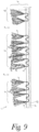
- This property can be obtained by the post-treatment of the hairs 4 or fibres 4, including the cutting of a composite thread, where the post-treatment also involves relaxation of the fibres from which the wire connection is made. This leads to the straightening of the hairs or fibres similar to the umbel inflorescence of a plant as shown, for example, in Figure 9 .
- the aforementioned part is preferably at least 15%, or better at least 250 or at least 350 of the hairs 4 upright oriented on the front of the first side 5 or the abrasive material sanding surface.
- the second side 9 of the abrasive material 1 is in this case, but not necessary for the invention, provided with a layer nonwoven 10. This can also be a layer of textiles or the like.
- the method for manufacturing the abrasive material 1 is very simple and as follows.
- FIG. 2 to 6 show the successive steps.
- this connection is a W-connection 3, which can be derived from the stitching of the connection 3.
- connection 3 is made using a heat-resistant material.
- connection of this double layer of fabric 2 is cut, as shown schematically in Figure 2 .
- connection 3 is fixed. This can be done, for example, by stitching the fabric 2.
- Figure 4 shows the next step, in which the hairs 4 are treated so that the shape of the hairs 4 is changed.
- the shape of the hairs 4 is curly after treatment. This gives the hairs 4 a resilience.
- the above treatment can be thermal or chemical, with the hairs 4 permanently deformed.
- the wires 3 are made of a composite wire with multiple fibres of a rigid plastic such as nylon.
- the fibres in such a composite wire are subject to a torsion tension that is released when cutting such a composite wire so that the constituent fibres detach completely or partially and open up spatially similar to the umbel (umbella) inflorescence of a plant.
- This relaxation step replaces or forms part of the aforementioned thermal or chemical treatment and gives rise to a material as shown in Figure 9 .
- the next step shown in Figure 5 is an optional additional step where a layer of nonwoven 10, but this may also be textile or similar, is applied to the second side 9 of the abrasive material 2.
- a binding is applied to the hairs 4. This binder will allow sanding particles 8 to attach to the hairs 4.
- the binder is a resin, for example.
- the nonwoven layer 10 from the previous step will stop the resin which is coming through the abrasive material 1.
- Figure 6 shows the last step where the abrasive particles 8 are applied to the hairs 4.
- these abrasive particles 8 are diamond particles.
- the abrasive material 1 is manufactured and ready for use.
- FIG. 7 A possible application for the use of abrasive material 1 is shown in figures 7 and 8 .
- Figure 7 shows an accessory 11 to a tool 12 containing an abrasive material 1 according to the invention.
- the accessory 11 has a three-dimensional design and in this case concerns a pad 11, for example a brushing, cleaning, sanding or polishing pad.
- the pad 11 has a disc shape and is covered with the abrasive material 1.
- the pad 11 is equipped with, for example, Velcro hooks which can attach to the nonwoven 10 on the second side 9 of the abrasive material 1, so that the abrasive material 1 can attach to the pad 11.
- the pad 11 has a sanding or polishing surface 13.
- the tool 12 on which the pad 11 is applied will allow the pad 11 to rotate at high speed.
- the tool 12 can then be placed on a surface to be sanded, brushed, cleaned or polished.
- the resilient hairs 4 will be able to sand, brush, clean or polish in the depth of the surface.
- the particles thus removed from the surface will be removed via the rills 7 and will not accumulate between the surface and the polishing surface 13 of the pad 11.
- Figure 8 shows a variant of an accessory 11 according to figure 7 , in which case the shape of the pad 11 is changed.
- the sanding and polishing surface 13 will exert an equal force throughout the surface due to its shape, so that the treatment will take place uniformly over the entire surface.
- the present invention is by no means limited to the embodiments described as examples and shown in the figures, but an abrasive material according to the invention, an accessory to an instrument containing such abrasive material and the method of manufacturing such abrasive material can be achieved according to different variants without acting outside the scope of the invention as defined by the appended claims.
- a characteristic of the abrasive according to the invention has to do with the upright orientation of the hairs, and in particular an orientation similar to the umbel (umbella) inflorescence of a plant.
- the abrasive material can add value to the various applications where typical nonwovens and brush hairs are used today.
- the slightly abrasive grains applied to the fibres help loosen dirt on the material to be cleaned.
- the shape, structure, and upright orientation of the bristles provide the necessary resilience, which we can also call brush power, as we zoom more closely into function and resilience, we see that because of the spatial orientation of the fibre ends, the strength is not only developed on the upper surface, but also in lower sections of the ecoforce, this in contrast to the classic sanding brushes and nonwoven open cell structures that generate these forces only at the front, at the highest points of their surface.
- the Ecoforce pad thus overlaps the current operation of the nonwovens and the brush pads and has unique properties with completely different end results without damaging the surface.
Landscapes
- Engineering & Computer Science (AREA)
- Mechanical Engineering (AREA)
- Manufacturing & Machinery (AREA)
- Polishing Bodies And Polishing Tools (AREA)
- Cleaning Implements For Floors, Carpets, Furniture, Walls, And The Like (AREA)
Description
- The present invention concerns an abrasive material and accessories to a tool containing such abrasive material.
- Abrasive materials are used to clean and/or polish floors, in particular stone floors, steel objects, wood surfaces and other elements.
- These abrasive materials are often incorporated into a cleaning pad, sanding pad, polishing pad or briefly also called "pad". These elements are indicated here as accessories to an instrument.
- The known abrasive materials contain interconnected but nonwoven fibres with resins and scattered with abrasive particles.
- Most of these known materials are manufactured using the felting method. The fibres are hooked together or connected at various intersections.
- This always results in layered cell structures.
- An accessory to a tool containing such abrasive material always involves a three-dimensional element, often developed as a thin layer but always with a thickness.
- These three-dimensional elements are always provided with at least one sanding or polishing surface, here often called the horizontal surface.
- Horizontal originates from the orientation of these structures in a pad when placed on a horizontal surface.
- The nonwoven structure of the fibres results in layered cell structures, and in the above context these are also referred to as horizontal cell structures.
- A disadvantage of these well-known abrasive materials is that they are easily hidden or clogged.
- The residues released during the cleaning or polishing process fill the pores of the material, with the adverse effect that these residues are deposited on the above-mentioned sanding or polishing surface, i.e. at the surface that makes contact with the surface to be sanded, polished or cleaned.
- Sometimes the residues will accumulate on the surface and thus result in an uneven surface. This occurs, for example, when sanding plaster plates.
- Other sanding materials are made of paper, resin and sanding particles.
-
WO 96/07509 -
DE 198 43 267 provides an abrasive material with standing hairs on one side of the abrasive material, but when in use, the hairs tend to come loose, which is detrimental to the durability of the material. - The present invention therefore aims to offer a solution to one or more of the aforementioned or possible other disadvantages.
- This concerns the invention of an abrasive material as provided in the appended claims, that includes a first side (5) and an opposite side (9), with the hairs (4) or fibers (4) on the first side of the abrasive material obtained from a double layer of fabric with a threaded connection cut in the middle to form the hairs or fibres on the first side of the abrasive material, where the hairs are post-treated so that the shape of the hairs is permanently changed, and where the hairs are equipped with abrasive particles.
- Characteristic of the double-layer fabric and as further explained here, is that the wires (3) that form the connection in the double-layer fabric are connected by a W-connection to the layers of the double-layer fabric . The abrasive material is therefore characterised by the fact that the wires are connected by a W-connection to the first (5) and an opposite second side (9) of the abrasive material.
- The after-treatment in question may be a heat treatment whereby the shape of the hairs is permanently changed by heating or a chemical treatment using chemicals that produce a similar effect. Such treatments are known from the fake fur industry.
- The after-treatment may also involve relaxation of the fibres from which the wire connection is made. This occurs, for example, when using a composite wire with multiple fibres of a rigid plastic such as nylon. The fibres in such a composite wire are subject to a torsion tension that is released when cutting such a composite wire so that the constituent fibres detach completely or partially and open up spatially similar to the umbel (umbella) inflorescence of a plant.
- In addition to the aforementioned W-shape for the connection of the wires with both sides of the abrasive material, the preparation from a cut double-layer fabric also ensures that the wires on the front of these sides stand up. A configuration that clearly differs from the aforementioned layered cell structures that we obtain based on the felting method. As explained in more detail, this vertical orientation of the wires results in a different function of the abrasive material obtained using the method described here.
- The abrasive particles mentioned are, for example, but not limited to, silicon carbide, diamond, cerium oxide, quartz, aluminium oxide or similar or a combination of two or more of the above.
- The application is carried out in a machine with the addition of the desired sanding particles. These abrasive particles are injected into the hair in the correct consistency.
- The above-mentioned first side (5) is also called the abrasive material's abrasive surface.
- The change in the shape of the fibres, also known as hairs, as a result of the aforementioned heat after-treatment or as a result of the relaxation of the torsion tension in the composite wires, contributes to the resilience of these fibres. This means that the fibres have a certain resilience.
- As a result, the fibres will be able to exert a force on each other, whereby the fibres extend spatially in different directions, but without losing their predominantly upright orientation on the front of the sanding surface.
- During the cleaning, sanding or polishing of a surface, the resilience and different orientation of the hairs will allow one hair or allow the other hair to penetrate, allowing an uneven surface to be cleaned, sanded or polished without loss of surface texture.
- In other words, because the fibres extend in the upright space on the surface of the sanding surface in several directions and because some fibres are directed transversely (perpendicularly) on the surface to be cleaned or polished, also called the "vertical" hairs or fibres, they will be able to clean, polish or sand in depth. As indicated above, the orientation of the fibres in the upright space on the front of the sanding surface can be compared with the space occupied by the side axles in an umbel (umbella) inflorescence of a plant.
- The name 'vertical' therefore originates from the orientation of these hairs on the front of the sanding surface in a pad when laid on a horizontal surface.
- The hairs preferably have a curly shape, round spiral shape, angular spiral shape or zigzag shape.
- As a result of this design, these vertical hairs or fibres exhibit resilient properties or display the necessary flexibility.
- Preferably, the length of the hair is between three millimetres and eighty millimetres.
- Such a long length of the hairs ensures that the abrasive material can clean even deeper, i.e. that a deeper effect of sanding, polishing or cleaning is obtained in the material. For example, it will be possible for the hairs to penetrate into wood grains and sand or clean them.
- It should be noted that the resilient properties of the hairs are essential to achieve a good function.
- Preferably, the connection of the double-layer fabric is made of heat-resistant material.
- This means that the aforementioned fibres or hairs are made of this heat-resistant material.
- The vertical hairs or fibres are preferably made from a heat-resistant plastic, which is heat-resistant up to 320°C with a melting point of 250°C under pressure,
e.g. nylon -
Nylon nylon 6 and/ornylon EP3497272 . - In a preferred form, the wires are BCF wires composed of
multiple nylon nylon - In addition to the aforementioned characteristics relating to the method of connection and orientation of the wires, the method of preparation from a double-layer weave has an additional advantage. It allows the wires to be placed in a pattern on the sanding surface, as for example grouped in rows, hereinafter also called brush rows.
- Preferably, the connection of the double-layer fabric is such that after the mid-cutting of this fabric, the hairs are grouped in brush rows.
- The spaces between the brush rows are also called rills. The distance between the open rills is set according to the application.
- The pattern may vary depending on the application and may range from completely densely woven to any combination of openings or rills, i.e. areas where hairs are left out. The quantity of hairs per cm2 and their combined length is also decisive in this claim and determines the application and application field.
- An advantage of this is that the particles or residues that come loose during the cleaning, polishing or sanding process can be removed via these rills when they are pushed out by the centrifugal force. They can then be sucked up by the machine.
- In other words, there will be no accumulation of these particles between the surface that is cleaned, polished or sanded and the abrasive material.
- Preferably, the hairs are provided with a binder to attach the abrasive particles to the hair.
- For example, this binder is a resin, a resin compound, a phenol resin, a compound of phenol resin, a polyurethane, an adhesive, or the like, which may be natural or chemical, or a combination or compounds thereof.
- In a so-called spraying machine, the aforementioned sanding particles are mixed together with a binder and sprayed onto the hairs under the correct consistency.
- The basic fabric can be produced in different ways.
- For example, a double layer connected fabric which is cut in the middle with an additional boucl6 yarn as a weft yarn.
- This bouclé yarn is used to form a kind of Velcro layer. After the weaving process, the semi-finished product is dried with a whipped coating (shaving foam) under an infrared table so that the loop remains facing upwards to create the Velcro effect.
- Alternatively, the tuft method is used whereby, after tufting, a Velcro weave is laminated or burned against a second side of the abrasive material, also called the back.
- In another embodiment, a layer of nonwoven, knitted textiles or the like (10) is applied a second side (9) of the abrasive material.
- Such a layer of nonwoven, knitted fabric or such is used to attach the abrasive material to a tool. To this end, the latter will contain a holder, also called a pad holder, to which the abrasive material can be attached. The shape of this pad holder will also influence the shape of the abrasive material, such as a disc shape for a disc-shaped pad holder, or a rectangular shape for attachment to a cylindrical pad holder, also called a roller brush. In a special embodiment, the pad holder will be disc-shaped, and will be fitted with hook-and-loop hooks on both sides, thus enabling a wraparound attachment of the abrasive material around the pad holder (See
figures 7 and 8 ). With such a wrapped pad holder there is a better range of the abrasive material in corners and edges of an object/surface to be treated. For the wrapping of a pad holder, the abrasive material's sanding or polishing surface may contain one or more cutouts. These cutouts are preferably configured to allow close connection of the abrasive material on the pad holder, for example in the form of flower cutouts. - An additional advantage of such a layer of nonwoven, knitted textiles or the like (10) is that it also serves as a membrane to prevent the aforementioned binder from sinking to the bottom and to prevent the loops from losing their function attachment with the Velcro hooks.
- As indicated above, the upright orientation of the hair is understood to mean that they focus spatially in line with the umbel (umbella) inflorescence of a plant. If we continue this analogy, we find that in this inflorescence, the side axles are mainly at an angle between 45° and 135° to the main axle or flower stem from which they depart. Also in the abrasive material according to this invention, the hairs will preferably be directed mainly at an angle between 45° and 135° with respect to the aforementioned first side or abrasive material sanding surface.
- The aforementioned part is preferably at least 15%, preferably at least 250 or at least 350 of the hair.
- The abrasive material can be applied in various ways.
- The invention also concerns an accessory to a tool containing an abrasive material according to the invention, where the accessory has a three-dimensional design and where the accessory concerns an abrasive brush pad, cleaning pad, sanding pad, polishing pad, roller brush or the like, which accessory is fitted with an abrasive or polishing surface as described herein.
- With regard to the constituents of the abrasive material according to the invention, the aforementioned sanding or polishing surface is often referred to here as the horizontal surface.
- According to a preferred form of implementation, the accessories to a tool containing such abrasive material are an abrasive roller brush where the diameter is determined by the tube and not by the length of the bristles.
- According to a preferred form of implementation, the accessories of a tool containing such abrasive material are an abrasive sanding pad for cleaning floors, consisting of stone, plastic, wood, metal or other compositions.
- According to a preferred form of implementation, the accessories of a tool containing such abrasive material are an abrasive roller brush for cleaning floors, consisting of stone, plastic, wood, metal or other compositions.
- Alternatively, the accessories, albeit an abrasive sanding pad or an abrasive roller brush, are used for sanding surfaces with the intention of removing material on stone, plastic, wood, metal or other compositions.
- The invention also involves a working method for the manufacture of an abrasive material having a first (5) and an opposite (9) side, including hairs (4) or fibres (4) on the first side (5) of the abrasive material (1), which means that the working method includes the following steps:
- A providing double-layer weave with a W-connection joint of a wire (3) through a top and bottom layer of the double-layer weave;
- B cutting the W-connection joint of the double-layer fabric in between the top and bottom layer of the double layer fabric to form a W-connection through the first side (5) and opposite (9) side of the abrasive material (1), and hairs or fibres on the first side of the abrasive material;
- C treat the hairs so that the shape of the hairs is changed;
- D the application of abrasive particles to the hairs.
- This method has the advantage that the abrasive material with the predominantly upright oriented hairs is manufactured according to the invention. As indicated above, this preparation method not only provides the aforementioned orientation, but also allows the wires to be placed in patterns on the sanding surface, including an orientation in brush rows with open rills, as well as in a variable density (number of wires per surface).
- Step C treatment may be heat treatment or chemical treatment with chemicals as mentioned above.
- Preferably, the procedure after the above-mentioned step C includes the additional step of applying a layer of nonwoven or knitting, textile or similar on a second side of the abrasive material.
- The advantage of this layer is that it can be used to attach the abrasive material, when incorporated in an accessory, to a tool by means of the Velcro principle.
- Preferably, the procedure for the aforementioned step D includes the additional step of applying a binder to the hairs to attach the abrasive particles to the hairs.
- With the help of this binder, the sanding particles can adhere well to the hairs or fibres.
- In this case, the above-mentioned layer of nonwoven or knitting has the additional advantage that the binder, for example a resin or other adhesive, when it passes through the abrasive material, is held back by this layer of nonwoven or knitting.
- In a further embodiment, the procedure may include a further step E in which the abrasive material obtained after step D is thermally compressed. By thermally compressing the material, the wires are shortened and the material gets more sanding power, without losing the aforementioned advantages associated with the upright orientation of the wires.
- With the insight to better demonstrate the characteristics of the invention, a few preferential variants of an abrasive material are described here according to the invention, an accessory to an instrument containing such abrasive material and the method of manufacturing such abrasive material, with reference to the accompanying drawings, in which:
-
figure 1 schematically represents a cross-section of an abrasive material according to the invention; -
figures 2 to 6 show the consecutive steps of the method according to the invention; -
figure 7 shows an accessory according to the invention; -
figure 8 shows an alternative offigure 7 ; -
figure 9 schematically represents a cross-section of an abrasive material according to the invention; -
Figure 1 schematically represents a cross-section of an abrasive material 1 according to the invention. - It comprises half of a double layer of
fabric 2 with connection 3 that is cut in the middle as shown infigure 2 . In the example shown, this connection 3 is a so-called W-connection 3 through afirst side 5 and oppositesecond side 9 of each layer from which the double layer fabric is constructed. - The connection 3 is therefore a wire 3 that is woven or stitched through both layers (top and bottom in
figure 2 ) of thedouble layer fabric 2 and connected by a W-connection to the first (5) and an opposite second side (9) of the abrasive material. - The connection 3 of the
double layer fabric 2, more specifically the wire 3 with which this connection 3 is made, is in this case, but not necessarily, made of a heat-resistant material. In a preferred form, the wire is a composite wire containing multiple hairs or fibres. - By cutting this connection 3, hairs 4 or fibres 4 are formed on the
first side 5 of the abrasive material 1. In this embodiment in which the wires are composed, the fibres will open spatially after cutting as shown inFigure 8 . - The fibres 4 are preferably grouped in so-called
brush rows 6. Theopen spaces 7 between thesebrush rows 6 are also calledrills 7. - The fibres 4 or hairs 4 thus created have been re-treated, resulting in permanent changes to their shape.
- In this case, the shape of the fibres 4 is a curl shape, but this can also be a round spiral shape, angular spiral shape, a zigzag shape or the like.
- The length L of these hairs 4 is in this case five millimetres, but this could also be ten, fifteen, thirty or, for example, fifty millimetres. Preferably the length L of the hairs 4 is between three millimetres and eighty millimetres.
- According to the invention, the hairs 4 have sanding
particles 8. - In this case the hairs 4 have a binder to attach the
sanding particles 8 to the hairs 4. This binder is not shown on the figures. - Although in
figure 1 all hairs 4 are represented as perpendicular to thefirst side 5 of the abrasive material 1, it must be taken into account that this is only a schematic representation. As described above, this upright orientation of the hairs means that they focus spatially in line with the umbel (umbella) inflorescence of a plant, as shown, for example, inFigure 9 . - In practice, not all hairs 4 will be oriented perpendicular to the
first side 5. - Preferably, at least part of the hairs 4 is directed mainly at an angle between 45° and 135° with respect to the aforementioned
first side 5 of the abrasive material 1. - This property can be obtained by the post-treatment of the hairs 4 or fibres 4, including the cutting of a composite thread, where the post-treatment also involves relaxation of the fibres from which the wire connection is made. This leads to the straightening of the hairs or fibres similar to the umbel inflorescence of a plant as shown, for example, in
Figure 9 . - The aforementioned part is preferably at least 15%, or better at least 250 or at least 350 of the hairs 4 upright oriented on the front of the
first side 5 or the abrasive material sanding surface. - The
second side 9 of the abrasive material 1 is in this case, but not necessary for the invention, provided with alayer nonwoven 10. This can also be a layer of textiles or the like. - The method for manufacturing the abrasive material 1 is very simple and as follows.
-
Figures 2 to 6 show the successive steps. - Starting from one
double layer fabric 2 with connection 3. - In this case, this connection is a W-connection 3, which can be derived from the stitching of the connection 3.
- In this case, the connection 3, as already mentioned, is made using a heat-resistant material.
- The connection of this double layer of
fabric 2 is cut, as shown schematically inFigure 2 . - This forms the hairs 4 on the
first side 5. - In a possible next step, as shown in
Figure 3 , the connection 3 is fixed. This can be done, for example, by stitching thefabric 2. -
Figure 4 shows the next step, in which the hairs 4 are treated so that the shape of the hairs 4 is changed. - The shape of the hairs 4 is curly after treatment. This gives the hairs 4 a resilience.
- The above treatment can be thermal or chemical, with the hairs 4 permanently deformed.
- In another embodiment, the wires 3 are made of a composite wire with multiple fibres of a rigid plastic such as nylon. The fibres in such a composite wire are subject to a torsion tension that is released when cutting such a composite wire so that the constituent fibres detach completely or partially and open up spatially similar to the umbel (umbella) inflorescence of a plant. This relaxation step replaces or forms part of the aforementioned thermal or chemical treatment and gives rise to a material as shown in
Figure 9 . - The next step shown in
Figure 5 is an optional additional step where a layer ofnonwoven 10, but this may also be textile or similar, is applied to thesecond side 9 of theabrasive material 2. - Then, in an optional step not shown in the figures, a binding is applied to the hairs 4. This binder will allow sanding
particles 8 to attach to the hairs 4. - The binder is a resin, for example.
- The
nonwoven layer 10 from the previous step will stop the resin which is coming through the abrasive material 1. -
Figure 6 shows the last step where theabrasive particles 8 are applied to the hairs 4. - For example, these
abrasive particles 8 are diamond particles. - In this way, the abrasive material 1 is manufactured and ready for use.
- A possible application for the use of abrasive material 1 is shown in
figures 7 and 8 . -
Figure 7 shows an accessory 11 to atool 12 containing an abrasive material 1 according to the invention. - The
accessory 11 has a three-dimensional design and in this case concerns apad 11, for example a brushing, cleaning, sanding or polishing pad. - The
pad 11 has a disc shape and is covered with the abrasive material 1. - To this end, the
pad 11 is equipped with, for example, Velcro hooks which can attach to the nonwoven 10 on thesecond side 9 of the abrasive material 1, so that the abrasive material 1 can attach to thepad 11. - By applying the abrasive material 1, the
pad 11 has a sanding or polishingsurface 13. - The
tool 12 on which thepad 11 is applied will allow thepad 11 to rotate at high speed. - The
tool 12 can then be placed on a surface to be sanded, brushed, cleaned or polished. - The resilient hairs 4 will be able to sand, brush, clean or polish in the depth of the surface. The particles thus removed from the surface will be removed via the
rills 7 and will not accumulate between the surface and the polishingsurface 13 of thepad 11. -
Figure 8 shows a variant of an accessory 11 according tofigure 7 , in which case the shape of thepad 11 is changed. - After all, it will be possible to give a specific shape to pad 11, which will allow for the sanding, brushing, cleaning or polishing of corners or special shapes.
- By giving the pad 11 a complementary shape according to the surface to be treated, special non-flat surfaces can also be treated.
- The sanding and polishing
surface 13 will exert an equal force throughout the surface due to its shape, so that the treatment will take place uniformly over the entire surface. The present invention is by no means limited to the embodiments described as examples and shown in the figures, but an abrasive material according to the invention, an accessory to an instrument containing such abrasive material and the method of manufacturing such abrasive material can be achieved according to different variants without acting outside the scope of the invention as defined by the appended claims. - A characteristic of the abrasive according to the invention has to do with the upright orientation of the hairs, and in particular an orientation similar to the umbel (umbella) inflorescence of a plant.
- A number of tests compared the effects of the abrasive material according to the invention (Ecoforce Green) with a classic nylon abrasive brush with stiff hairs without abrasives, and a nonwoven abrasive material with a horizontal open cell structure with silica, diamond and alum oxide as abrasives.
-
Nylon Brush Nonwoven pad Ecoforce green Teak 3 min /rotation /water Teak 3 min /rotation /water Teak 3 min /rotation /water - Remove surface contamination - Remove surface contamination - Good surface area and deep cleaning - No deep cleaning - Limited visual damage to materials - No visible damage to materials - No material damage Result after 3 min idle cleaning Result after 3 min idle cleaning Result after 3 min idle cleaning - The brush only removes dirt on the surface - Abrasion is obtained. - Good surface area and deep cleaning - Visible damage to the material - No visible damage to materials - No deep cleaning - No material damage -
Nylon Brush Nonwoven pad Ecoforce green Linoleum 3 min /rotation /water Linoleum 3 min /rotation /water Linoleum 3 min /rotation /water No visible effect on this material. A superficial effect, with hints of abrasion on the treated material. A clear cleaning effect both at the surface and in depth without leaving sanding stripes. Visually innovative effect for the treated material. -
Nylon Brush Nonwoven pad Ecoforce green Floor tiles 3 min /rotation /water Floor tiles 3 min /rotation /water Floor tiles 3 min /rotation /water Surface cleaning of the tiles. Surface cleaning of the tiles. Surface cleaning of the tiles. No effect on joints. No effect on joints Deep cleaning of the joints. -
Nylon Brush Nonwoven pad Ecoforce green Granite top 3 min /rotation /water Granite top 3 min /rotation /water Granite top 3 min /rotation /water Surface cleaning. Visible effect after a few minutes. Visible effect after a few minutes. No deep cleaning. Fast pad wear. No visible pad wear. Limited deep cleaning and requires additional chemicals for this. Deep cleaning without additional chemicals. Visually innovative effect for the treated material - The above experiments show that according to the invention, the abrasive material can add value to the various applications where typical nonwovens and brush hairs are used today. We have found that because of the upright fibre form, its resilience really allows for better penetration in depth and more effective cleaning without compromising on chemical agents, like ordinary waste deposits. The slightly abrasive grains applied to the fibres help loosen dirt on the material to be cleaned.
- The shape, structure, and upright orientation of the bristles provide the necessary resilience, which we can also call brush power, as we zoom more closely into function and resilience, we see that because of the spatial orientation of the fibre ends, the strength is not only developed on the upper surface, but also in lower sections of the ecoforce, this in contrast to the classic sanding brushes and nonwoven open cell structures that generate these forces only at the front, at the highest points of their surface.
- The tests also showed that the resilience ensures that the structure of a surface is not affected and only the dirt is detached, unlike the other materials tested.
- The tests have also shown that the length and resilience of the hairs ensures that sanding is not possible or only to a limited extent, even with coarse grains, (data not shown). To achieve an abrasive effect, the fibres must be shortened.
- The Ecoforce pad thus overlaps the current operation of the nonwovens and the brush pads and has unique properties with completely different end results without damaging the surface.
Claims (16)
- Abrasive material, wherein the abrasive material (1) includes a first (5) and an opposite (9) side, including hairs (4) or fibres (4) on the first side (5) of the abrasive material, characterized in that the hairs (4) or fibers (4) on the first side (5) of the abrasive material (1) are formed by starting from one double layer fabric (2) with a woven or stitched W-connection of a wire (3) through a top and a bottom layer of the double layer fabric (2) and cutting this W-connection in between the top and bottom layer of the double layer fabric (2), thereby obtaining a W-connection through the first side (5) and opposite side (9) of the abrasive material (1) and forming the hairs (4) or fibers (4) on a first side (5) of the abrasive material (1), in which the hairs (4) are post-treated so that the shape of the hairs (4) is permanently changed, and in which the hairs (4) are equipped with abrasive particles (8).
- Abrasive material according to claim 1, thus characterised that the wires are composite wires with fibres of a rigid plastic such as nylon.
- Abrasive material according to claim 1, thus characterised that the hairs (4) are equipped with a binder to attach the abrasive particles (8) to the hairs.
- Abrasive material according to claim 1 or 2, thus characterised that the hairs (4) have a curly shape, round spiral shape, angular spiral shape or zigzag shape.
- Abrasive material according to claim 1 or 2, therefore characterised by the hairs (4) extending in multiple directions in the upright space on the first side (5).
- Abrasive material according to one of the previous claims, therefore characterised that at least part of the hairs (4) is directed at an angle between 45° and 135° compared to the aforementioned first side (5) of the abrasive material (1) .
- Abrasive material according to one of the previous claims, thus characterised that on the opposite side (9) of the abrasive material (1) a layer of nonwoven (10) textile is applied.
- Abrasive material according to one of the previous claims, therefore characterised that the length (L) of the hairs (4) is between three millimetres and eighty millimetres.
- Abrasive material according to one of the previous claims, therefore characterised that the double-layer; fabric (2) is fitted with a weft yarn of bouclé yarn.
- Abrasive material according to one of the previous claims, characterised in that the hairs (4) are grouped in brush rows (6).
- Abrasive material according to one of the previous claims, characterised in that the fibres or hairs are made of heat-resistant material.
- Method of manufacture of an abrasive material, wherein the abrasive material (1) includes a first (5) and an opposite (9) side, including hairs (4) or fibres (4) on the first side (5) of the abrasive material (1) characterised by the following steps:A - providing double layer fabric (2) with connection (3) with a woven or stitched W-connection of a wire (3) through a top and a bottom layer of the double layer tissue (2);B - cutting the W-connection (3) of the double-layer fabric in between the top and bottom layer of the double layer fabric (2) to form a W-connection through the first side (5) and opposite side (9) of the abrasive material (1) and hairs (4) or fibres (4) on the first side (5) of the abrasive material (1);C - treating the hairs (4) so that the shape of the hairs is changed;D - applying abrasive particles (8) to the hairs (4).
- Method according to claim 12, wherein after the aforementioned step C, the method includes the additional step of applying a layer of nonwoven (10), textile or similar on the opposite side (9) of the abrasive material (1).
- Method according to claim 12 or 13, characterised by the fact that for the aforementioned step D, the working method includes the additional step of applying a binder to the hairs (4) to attach the abrasive particles (8) to the hairs (4).
- Method according to one of the previous claims 12 to 14, wherein the working method includes a further step E in which the abrasive material obtained after step D is thermally compressed.
- Accessory for a tool (12), the accessory containing an abrasive material in accordance with one of the previous claims 1 to 11, characterised by the fact that the accessory (11) has a three-dimensional design and that the accessory is in use an abrasive brush pad, cleaning pad, sanding pad, polishing pad or roller brush, which has through the application of the abrasive material a sanding or polishing surface (13).
Applications Claiming Priority (2)
| Application Number | Priority Date | Filing Date | Title |
|---|---|---|---|
| BE20205822A BE1028801B1 (en) | 2020-11-16 | 2020-11-16 | Abrasive material, accessories to a tool containing such abrasive material and method for producing such abrasive material |
| PCT/IB2021/060555 WO2022101873A1 (en) | 2020-11-16 | 2021-11-15 | Abrasive material, accessories for a tool containing such abrasive material and method of manufacturing such abrasive material |
Publications (3)
| Publication Number | Publication Date |
|---|---|
| EP4244021A1 EP4244021A1 (en) | 2023-09-20 |
| EP4244021B1 true EP4244021B1 (en) | 2024-05-29 |
| EP4244021C0 EP4244021C0 (en) | 2024-05-29 |
Family
ID=73543936
Family Applications (1)
| Application Number | Title | Priority Date | Filing Date |
|---|---|---|---|
| EP21814888.0A Active EP4244021B1 (en) | 2020-11-16 | 2021-11-15 | Abrasive material, accessories for a tool containing such abrasive material and method of manufacturing such abrasive material |
Country Status (12)
| Country | Link |
|---|---|
| US (1) | US20240066666A1 (en) |
| EP (1) | EP4244021B1 (en) |
| JP (1) | JP2023554232A (en) |
| KR (1) | KR20230118857A (en) |
| CN (1) | CN116600939A (en) |
| AU (1) | AU2021378522A1 (en) |
| BE (1) | BE1028801B1 (en) |
| CA (1) | CA3202099A1 (en) |
| IL (1) | IL302785A (en) |
| MX (1) | MX2023005610A (en) |
| WO (1) | WO2022101873A1 (en) |
| ZA (1) | ZA202305328B (en) |
Family Cites Families (4)
| Publication number | Priority date | Publication date | Assignee | Title |
|---|---|---|---|---|
| GB1539477A (en) * | 1977-12-07 | 1979-01-31 | Flock Dev & Res Co Ltd | Cleaning product |
| FI96585C (en) | 1994-09-06 | 1996-07-25 | Kwh Mirka Ab Oy | sanding |
| DE19843267A1 (en) * | 1998-09-21 | 2000-03-23 | Martin Wiemann | Buffing wheel |
| IT201600083786A1 (en) | 2016-08-09 | 2018-02-09 | Bibielle S P A | Process and equipment for the production of multi-filament BCF multi-filament BCF yarns and three-dimensional texturing, yarns thus obtained and their applications |
-
2020
- 2020-11-16 BE BE20205822A patent/BE1028801B1/en not_active IP Right Cessation
-
2021
- 2021-11-15 JP JP2023528952A patent/JP2023554232A/en active Pending
- 2021-11-15 IL IL302785A patent/IL302785A/en unknown
- 2021-11-15 US US18/036,758 patent/US20240066666A1/en active Pending
- 2021-11-15 AU AU2021378522A patent/AU2021378522A1/en active Pending
- 2021-11-15 CN CN202180085036.2A patent/CN116600939A/en active Pending
- 2021-11-15 KR KR1020237020075A patent/KR20230118857A/en unknown
- 2021-11-15 MX MX2023005610A patent/MX2023005610A/en unknown
- 2021-11-15 CA CA3202099A patent/CA3202099A1/en active Pending
- 2021-11-15 WO PCT/IB2021/060555 patent/WO2022101873A1/en active Application Filing
- 2021-11-15 EP EP21814888.0A patent/EP4244021B1/en active Active
-
2023
- 2023-05-16 ZA ZA2023/05328A patent/ZA202305328B/en unknown
Also Published As
| Publication number | Publication date |
|---|---|
| ZA202305328B (en) | 2023-12-20 |
| MX2023005610A (en) | 2023-07-12 |
| JP2023554232A (en) | 2023-12-27 |
| WO2022101873A1 (en) | 2022-05-19 |
| BE1028801A1 (en) | 2022-06-10 |
| AU2021378522A1 (en) | 2023-06-29 |
| BE1028801B1 (en) | 2022-06-13 |
| IL302785A (en) | 2023-07-01 |
| US20240066666A1 (en) | 2024-02-29 |
| CA3202099A1 (en) | 2022-05-19 |
| EP4244021A1 (en) | 2023-09-20 |
| EP4244021C0 (en) | 2024-05-29 |
| CN116600939A (en) | 2023-08-15 |
| KR20230118857A (en) | 2023-08-14 |
Similar Documents
| Publication | Publication Date | Title |
|---|---|---|
| US5725927A (en) | Cleaning cloth | |
| CN108495962A (en) | Scouring pad and scrubbing method | |
| US20070212965A1 (en) | Scrub pad with printed rigid plates and associated methods | |
| KR20100092459A (en) | Color changing wear indicator | |
| US20070271719A1 (en) | Cleaning Cloth | |
| PT804316E (en) | DEVICE FOR MECHANICAL SURFACE TARTING | |
| JP2006055994A (en) | Polished surface processing material | |
| US20070079462A1 (en) | Scouring web and method of making | |
| JPH10507973A (en) | Abrasive product and method of manufacturing the same | |
| JP2008509765A (en) | Scraping element for cleaning difficult to reach areas | |
| WO2011098409A1 (en) | Floor-polishing and -cleaning body | |
| EP2755799A1 (en) | Method of refurbishing vinyl composition tile | |
| EP4244021B1 (en) | Abrasive material, accessories for a tool containing such abrasive material and method of manufacturing such abrasive material | |
| CN1754996A (en) | Three dimensional textile article with emerging pile yarns, maintenance and/or cleaning tool, its manufacture | |
| JP2000080558A5 (en) | ||
| EP2042266A2 (en) | Smoothing and/or lapping tool particularly for finishing stone materials | |
| CA2773758C (en) | Scrub pad with printed rigid plates and associated methods | |
| EA046770B1 (en) | ABRASIVE MATERIAL, AUXILIARY ELEMENTS FOR TOOLS CONTAINING SUCH ABRASIVE MATERIAL, AND METHOD FOR MANUFACTURING SUCH ABRASIVE MATERIAL | |
| USRE31745E (en) | Composite brush | |
| AU2015379584B2 (en) | A polishing pad and material and manufacturing method for such | |
| JP7246411B2 (en) | Scouring article having a mixture of abrasive particles | |
| US20230249317A1 (en) | Abrasive product and method for manufacturing abrasive product | |
| RU2772324C1 (en) | Household abrasive article with two functional sides, abrasive fabric for household articles and method for manufacturing said abrasive fabric | |
| CN207118727U (en) | Brush filament and household cleaning brush | |
| DE202012003420U1 (en) | Grinding and cleaning body |
Legal Events
| Date | Code | Title | Description |
|---|---|---|---|
| STAA | Information on the status of an ep patent application or granted ep patent |
Free format text: STATUS: UNKNOWN |
|
| STAA | Information on the status of an ep patent application or granted ep patent |
Free format text: STATUS: THE INTERNATIONAL PUBLICATION HAS BEEN MADE |
|
| PUAI | Public reference made under article 153(3) epc to a published international application that has entered the european phase |
Free format text: ORIGINAL CODE: 0009012 |
|
| STAA | Information on the status of an ep patent application or granted ep patent |
Free format text: STATUS: REQUEST FOR EXAMINATION WAS MADE |
|
| 17P | Request for examination filed |
Effective date: 20230522 |
|
| AK | Designated contracting states |
Kind code of ref document: A1 Designated state(s): AL AT BE BG CH CY CZ DE DK EE ES FI FR GB GR HR HU IE IS IT LI LT LU LV MC MK MT NL NO PL PT RO RS SE SI SK SM TR |
|
| GRAP | Despatch of communication of intention to grant a patent |
Free format text: ORIGINAL CODE: EPIDOSNIGR1 |
|
| STAA | Information on the status of an ep patent application or granted ep patent |
Free format text: STATUS: GRANT OF PATENT IS INTENDED |
|
| DAV | Request for validation of the european patent (deleted) | ||
| DAX | Request for extension of the european patent (deleted) | ||
| INTG | Intention to grant announced |
Effective date: 20240202 |
|
| GRAS | Grant fee paid |
Free format text: ORIGINAL CODE: EPIDOSNIGR3 |
|
| GRAA | (expected) grant |
Free format text: ORIGINAL CODE: 0009210 |
|
| STAA | Information on the status of an ep patent application or granted ep patent |
Free format text: STATUS: THE PATENT HAS BEEN GRANTED |
|
| AK | Designated contracting states |
Kind code of ref document: B1 Designated state(s): AL AT BE BG CH CY CZ DE DK EE ES FI FR GB GR HR HU IE IS IT LI LT LU LV MC MK MT NL NO PL PT RO RS SE SI SK SM TR |
|
| REG | Reference to a national code |
Ref country code: CH Ref legal event code: EP |
|
| REG | Reference to a national code |
Ref country code: IE Ref legal event code: FG4D |
|
| REG | Reference to a national code |
Ref country code: DE Ref legal event code: R096 Ref document number: 602021013938 Country of ref document: DE |
|
| U01 | Request for unitary effect filed |
Effective date: 20240617 |
|
| U07 | Unitary effect registered |
Designated state(s): AT BE BG DE DK EE FI FR IT LT LU LV MT NL PT SE SI Effective date: 20240627 |