EP4243584A1 - Immersion cooling apparatus - Google Patents
Immersion cooling apparatus Download PDFInfo
- Publication number
- EP4243584A1 EP4243584A1 EP22175962.4A EP22175962A EP4243584A1 EP 4243584 A1 EP4243584 A1 EP 4243584A1 EP 22175962 A EP22175962 A EP 22175962A EP 4243584 A1 EP4243584 A1 EP 4243584A1
- Authority
- EP
- European Patent Office
- Prior art keywords
- coolant
- circuit board
- lid
- pressure vessel
- mounting member
- Prior art date
- Legal status (The legal status is an assumption and is not a legal conclusion. Google has not performed a legal analysis and makes no representation as to the accuracy of the status listed.)
- Pending
Links
Images




Classifications
-
- H—ELECTRICITY
- H05—ELECTRIC TECHNIQUES NOT OTHERWISE PROVIDED FOR
- H05K—PRINTED CIRCUITS; CASINGS OR CONSTRUCTIONAL DETAILS OF ELECTRIC APPARATUS; MANUFACTURE OF ASSEMBLAGES OF ELECTRICAL COMPONENTS
- H05K7/00—Constructional details common to different types of electric apparatus
- H05K7/20—Modifications to facilitate cooling, ventilating, or heating
- H05K7/20218—Modifications to facilitate cooling, ventilating, or heating using a liquid coolant without phase change in electronic enclosures
- H05K7/20236—Modifications to facilitate cooling, ventilating, or heating using a liquid coolant without phase change in electronic enclosures by immersion
-
- H—ELECTRICITY
- H05—ELECTRIC TECHNIQUES NOT OTHERWISE PROVIDED FOR
- H05K—PRINTED CIRCUITS; CASINGS OR CONSTRUCTIONAL DETAILS OF ELECTRIC APPARATUS; MANUFACTURE OF ASSEMBLAGES OF ELECTRICAL COMPONENTS
- H05K7/00—Constructional details common to different types of electric apparatus
- H05K7/20—Modifications to facilitate cooling, ventilating, or heating
- H05K7/20218—Modifications to facilitate cooling, ventilating, or heating using a liquid coolant without phase change in electronic enclosures
- H05K7/20272—Accessories for moving fluid, for expanding fluid, for connecting fluid conduits, for distributing fluid, for removing gas or for preventing leakage, e.g. pumps, tanks or manifolds
-
- H—ELECTRICITY
- H05—ELECTRIC TECHNIQUES NOT OTHERWISE PROVIDED FOR
- H05K—PRINTED CIRCUITS; CASINGS OR CONSTRUCTIONAL DETAILS OF ELECTRIC APPARATUS; MANUFACTURE OF ASSEMBLAGES OF ELECTRICAL COMPONENTS
- H05K7/00—Constructional details common to different types of electric apparatus
- H05K7/20—Modifications to facilitate cooling, ventilating, or heating
- H05K7/20709—Modifications to facilitate cooling, ventilating, or heating for server racks or cabinets; for data centers, e.g. 19-inch computer racks
- H05K7/20763—Liquid cooling without phase change
- H05K7/20772—Liquid cooling without phase change within server blades for removing heat from heat source
-
- H—ELECTRICITY
- H05—ELECTRIC TECHNIQUES NOT OTHERWISE PROVIDED FOR
- H05K—PRINTED CIRCUITS; CASINGS OR CONSTRUCTIONAL DETAILS OF ELECTRIC APPARATUS; MANUFACTURE OF ASSEMBLAGES OF ELECTRICAL COMPONENTS
- H05K7/00—Constructional details common to different types of electric apparatus
- H05K7/20—Modifications to facilitate cooling, ventilating, or heating
- H05K7/20709—Modifications to facilitate cooling, ventilating, or heating for server racks or cabinets; for data centers, e.g. 19-inch computer racks
- H05K7/20763—Liquid cooling without phase change
- H05K7/20781—Liquid cooling without phase change within cabinets for removing heat from server blades
Definitions
- the present application relates to techniques for cooling electronic equipment that generates heat.
- Recent electronic equipment includes a lot of semiconductor circuits, and in particular, integrated circuits such as central processing units (CPUs) or processors are essential electronic components for performing various controls of electronic devices.
- CPUs central processing units
- processors are essential electronic components for performing various controls of electronic devices.
- consumer-oriented electronic components are not designed for use in harsh environments. Accordingly, ruggedizing techniques are indispensable in the case where the electronic equipment is expected to be used in environments outside normal ranges of temperature, pressure, vibration, etc.
- JP2002-166899 discloses a space-environment ruggedizing container for protecting consumer electronic components from cosmic rays.
- This space-environment ruggedizing container is made of aluminum 3 millimeters in thickness, aiming to reduce weight and reliably shield cosmic rays (mainly electrons and protons).
- many electronic components include semiconductor circuits (e.g., processors) that generate heat during operation.
- semiconductor circuits e.g., processors
- heat-generating electronic components are sealed within a container, it is necessary to provide a means of dissipating heat to outside.
- electronic equipment mounted on an artificial satellite includes circuit boards containing integrated circuits that perform high-speed calculations with high heat generation. Accordingly, not only ruggedizing but also cooling is an indispensable technique.
- Patent Document 1 discloses a structure in which a cooling plate is provided on the bottom plate of a container to conduct heat generated by electronic components to the outside for heat exhaustion.
- JP H07-025395 discloses a heat dissipation device that improves heat dissipation efficiency. More specifically, a heat pipe mounted on the heat-generating part of an onboard device of a satellite is joined to a heat pipe mounted on the heat dissipation part outside the heat-generating part.
- Patent document 3 JP Patent No. 6720752 (hereinafter, referred to as Patent document 3), an electronic device is immersed in a coolant bath filled with a first coolant.
- a liquid cooling jacket is provided to cool the electronic device by flowing a second coolant from the outside into the liquid cooling jacket.
- a liquid flow generator is provided in the coolant bath to flow the first coolant in the coolant bath for enhanced cooling efficiency.
- Patent document 4 9750159B2 (hereinafter, referred to as Patent document 4) also discloses a liquid immersion cooling device that flows a coolant by means of a pump, and describes an example of efficiently dissipating heat from electronic components by convection and boiling of the coolant.
- the immersion cooling devices described in Patent documents 3 and 4 employ a cooling system designed for normal use on the ground. In other words, they are not designed for use in harsh environment such as zero-gravity environment and extreme conditions of substantial vibrations when launched by a rocket. Therefore, when such an immersion cooling device is mounted on a spacecraft as it is, the convection of the coolant does not occur in weightless space, and bubbles due to boiling do not remove from heat dissipation fins, causing dry-out phenomenon.
- An object of the present invention is to provide an immersion cooling device which allows enhanced resistance to harsh environment, increased cooling efficiency, and easy design and manufacturing.
- an immersion cooling apparatus for a circuit board including a heat-generating section includes: a pressure vessel including a vessel body and at least one lid, wherein the at least one lid is detachably joined to the vessel body, wherein a certain lid of the at least one lid has a coolant outlet and a coolant inlet, wherein the pressure vessel is filled with liquid coolant; and a mounting member that places the circuit board at a position between the coolant outlet and the coolant inlet within the pressure vessel, wherein the circuit board is immersed in the liquid coolant within the pressure vessel such the circuit board is surrounded with the liquid coolant, wherein the liquid coolant forcedly flows from one side of the circuit board to outside the pressure vessel through the coolant outlet and forcedly flows into the other side of the circuit board from outside the pressure vessel through the coolant inlet.
- the circuit board is immersed in the liquid coolant and securely placed in the pressure vessel with the liquid coolant forcedly flowing along the circuit board. This enhances resistance to harsh environments and improves cooling efficiency. Further the coolant outlet and coolant inlet are provided on one lid of the pressure vessel, resulting in simplified design and manufacturing.
- a pressure vessel composed of at least one detachable lid and a vessel body is filled with a coolant, and a circuit board is placed and immersed in the coolant within the pressure vessel.
- One lid has a coolant inlet and a coolant outlet, through which the coolant is forced to circulate. Furthermore, both ends of the circuit board are secured by mounting members provided in the vessel body.
- the coolant flows into the pressure vessel from the coolant inlet by means of a forced-liquid flow generator installed outside the pressure vessel.
- the coolant flows into the pressure vessel through the coolant inlet, flows over the front and back surfaces of the circuit board, and flows out through the coolant outlet.
- the coolant inlet and the coolant outlet are provided in the same lid, and the coolant flows in through the coolant inlet, flows on one side of the circuit board, flows along the inner surface of the pressure vessel to the other side of the circuit board, and flows out through the coolant outlet. Accordingly, the space around the circuit board is filled with flowing coolant, allowing efficient cooling.
- the circuit board is immersed in the coolant and surrounded by the pressure vessel, and both ends of the circuit board are secured by mounting members within the pressure vessel, allowing enhanced resistance to harsh environment.
- the circuit board has excellent resistance to harsh environments such as extremely cold/hot regions and the outer space, as well as environments subjected to substantial vibrations during rocket launches or the like.
- the electronic circuit board can be easily installed in the pressure vessel by simply detaching the lid from the vessel body, placing the electronic circuit board in the vessel body, and then joining the lid and the vessel body.
- the pressure vessel is divided into three sections: the vessel body having openings on both opposite surfaces; and a pair of lids each covering the openings of the vessel body.
- One of the lids is provided with the coolant inlet and the coolant outlet, and the other is provided with electrical terminals.
- the coolant inlet and the coolant outlet are provided on one lid, allowing the thermal control system including the heat dissipation mechanism and the forced-liquid flow generator such as a pump to be arranged on the side of the one lid.
- the thermal control system including the heat dissipation mechanism and the forced-liquid flow generator such as a pump
- the coolant that flows out through the coolant outlet of the pressure vessel is cooled by the thermal control system and then returned to the pressure vessel through the coolant inlet, to form a circulation system.
- the coolant on the electronic circuit board is forced to flow by the forced-liquid flow generator, the heat generated on the electronic circuit board can be dissipated to outside, thereby efficiently cooling the electronic circuit board. Accordingly, t the dry-out phenomenon can be prevented from occurring on the electronic circuit even in a space where gravity can be ignored.
- an immersion cooling apparatus 10 comprises a pressure vessel 100 and a thermal control system 200.
- the pressure vessel 100 comprises a cylindrical vessel body 101 and first and second lids 110 and 120.
- the first and second lids 110 and 120 are detachably connected to opposing opening surfaces of the vessel body 101, respectively.
- the pressure vessel 100 seals in coolant 130.
- the first lid 110 and the second lid 120 are hermetically joined to the opening surfaces on both sides of the vessel body 101 by a plurality of bolts 102 or other joining members.
- the first lid 110 is used for the coolant system and the second lid 120 for the electrical system.
- the vessel body 101 is provided with a mounting member composed of mounting flanges 103 and 104, which are centrally provided at both ends of the vessel body 101.
- the mounting flanges 103 and 104 are used to secure a plate 140 as described below.
- the vessel body 101 has flanges 105 and 106 protruding outward from both opening ends of the vessel body 101. These flanges 105 and 106 are used to join the first lid 110 and the second lid 120 to the vessel body 101.
- the first lid 110 has a coolant outlet 111 and a coolant inlet 112.
- the coolant 130 flows out through the coolant outlet 111.
- Coolant 130 that has been temperature-controlled by the thermal control system 200 flows in through the coolant inlet 112.
- sensors 113 for detecting the pressure and temperature in the pressure vessel 100 are provided at a position closer to the coolant outlet 111 between the coolant outlet 111 and the coolant inlet 112.
- the first lid 110 also has a flange 114 protruding inward at a position between the pressure and temperature sensors 113 and the coolant inlet 112 such that the flange 114 comes into contact with the mounting flange 103 of the vessel body 101.
- the flange 114 and the mounting flange 103 are combined to form a partition wall that partitions the inside of the pressure vessel 100 on the side of the first lid 110 vertically (in the top-and-bottom direction of Fig. 1 ) as shown in Figs. 1 and 3 . Accordingly, the flange 114 and the mounting flange 103 as the partition wall prevents the coolant 130 from directly flowing from the coolant inlet 112 to the pressure and temperature sensors 113 and the coolant outlet 111.
- the first lid 110 has a flange 115 protruding outward from the opening end of the first lid 110.
- the flange 115 is used to join the first lid 110 to the flange 105 of the vessel body 101 by joining members 102 (see Fig. 2 ).
- the second lid 120 has hermetic terminals 121 at the approximately central portion of the second lid 120.
- the hermetic terminals 121 are electrical terminals for sending and receiving signals to and from the outside and for receiving power supply.
- the hermetic terminals 121 are connected to a connector 123 through a cable 122 in the coolant 103 and the connector 123 is connected to a connector 142 mounted on a circuit board 141.
- the second lid 120 has a flange 124 protruding outward from the opening end of the second lid 120.
- the flange 124 is used to join the second lid 120 to the flange 106 of the vessel body 101 by joining members 102 (see Fig. 2 ).
- the plate 140 is supported and secured at both ends thereof by the mounting flanges 103 and 104.
- the circuit board 141 is fixed to the surface of the plate 140 on the side of the coolant outlet 111.
- Heat-dissipating fins 143 are fixed to the surface of the plate 140 on the side of the coolant inlet 112.
- a connector 142 is provided at the end of the circuit board 141 on the side of the second lid 120. As described above, the connector 142 is connected to the hermetic terminals 121 through the connector 123 and the cable 122, allowing signal transmission and power supply between the circuit board 141 and the outside.
- the thermal control system 200 includes a pipe arrangement connecting the coolant outlet 111 and the coolant inlet 112; a valve 202 provided near the coolant outlet 111; a pump 203 which is a forced-liquid flow generator located near the coolant inlet 112; an accumulator 204 with heating means; and a radiator plate 205 coupled to the pipe arrangement 201 by radiation.
- the pump 203 drives the coolant 13 in the pressure vessel 100 to flow from the coolant outlet 111 to the valve 202 and the pipe arrangement 201.
- the heat of the coolant flowing through the pipe arrangement 201 is dissipated into outside by the radiator plate 205. (see Fig. 1 ).
- the pump 203 drives the coolant thus cooled to flow into the pressure vessel 100 through the coolant inlet 112.
- the cooled coolant flows over the heat-dissipating fins 143 and the circuit board 141 to cool them. Even if heat of the heat-dissipating fins 143 and the circuit board 141 causes coolant 130 to vaporize to generate bubbles BB, the pump 203 forcedly flows the bubbles BB flow together with the coolant 130 and then the bubbles BB condense near the inner wall of the pressure vessel 100. In this way, the coolant 130 circulates through the interior of the pressure vessel 100 and the pipe arrangement 201 of the thermal control system 200 between the coolant outlet 111 and the coolant inlet 112.
- the accumulator 204 is a vessel which is equipped with a heater inside and temporarily stores gas/liquid. Accordingly, the heater in the accumulator 204 can be controlled to adjust the pressure and temperature of the coolant 130 to a state suitable for phase change (vaporization and condensation).
- the plate 140 mounted with the circuit board 141 and the heat-dissipating fins 143 is fixed on the mounting flanges 103 and 104 of the vessel body 101 by tap bolts 107 and 108.
- the mounting flanges 103 and 104 have clearance holes through which the tap bolts 107 and 108 pass, allowing for visual inspection when tightening the tap bolts 107 and 108 to mount the plate 140 to the mounting flanges 103 and 104, and facilitating work when attaching the tap bolts 107 and 108.
- the circuit board 141 on the plate 140 is fixed and placed in the near central portion of the vessel body 101.
- the pressure vessel 100 and thermal control system 200 described above are fixed to a mount panel 300 of a satellite or the like by supporting legs 301 and 302.
- the pipe arrangement 201, the pump 203, the accumulator 204 and the radiator plate 205 of the thermal control system 200 are also supported and secured to the mount panel 300 by support members (not shown) to prevent them from coming off due to vibrations or the like.
- Fig. 5 illustrates an appearance of the pressure vessel 100 more specifically.
- the similar components as in Figs. 1-4 are labeled with the same reference numbers.
- a slot card 144 can be mounted on the circuit board 141 with spacers 145 such that the slot card 144 is connected to the circuit board 141 through an immersion-dedicated cable 146 and a connector 147. Since the slot card 144 is mounted parallel to the circuit board 141 as shown in Fig. 6 , the performance of a processor and other devices can be expanded without increasing the diameter of the vessel body 101. In addition, cooling efficiency can be maintained because the flow of coolant 130 is not impeded.
- the circuit board 141 and expansion slot cards can be arranged flexibly in the pressure vessel 100. More specifically, although expansion slot cards are usually mounted perpendicular to the circuit board, it is possible to mount the expansion slot cards parallel to the circuit board 141, allowing the pressure vessel 100 to be downsized without unnecessarily widening its diameter.
- the processor and other components on the circuit board 141 are connected to operation equipment 501 and a power supply 502 provided outside the pressure vessel 100 through the hermetic terminals 121.
- the operation equipment 501 can send commands to operate the circuit board 141 by software and receive response data accordingly.
- the power supply 502 supplies power to the circuit board 141.
- the functional configuration of the immersion cooling apparatus 10 will be described, assuming that the immersion cooling apparatus 10 is mounted on a satellite which is an example of a space vehicle.
- the driver system 600 controls the pump 203 and the accumulator 204 of the thermal control system 20 under the control of the circuit board 141.
- the operation equipment 501 inputs the pressure of the pressure vessel 100 and the temperature of the coolant from the pressure and temperature sensors 113 and sends operating commands including the pressure and temperature data to the circuit board 141.
- the processor on the circuit board 141 sends control data of the driver system 600 to the driver system 600 through the operation equipment 501 according to the pressure and temperature data to adjust the pressure of the pressure vessel 100 and the temperature of the coolant. More specifically, while monitoring the detection data from the pressure and temperature sensors 113, the pump 203 is driven and the heater temperature of the accumulator 204 is adjusted to control the temperature of the coolant 130 to a temperature suitable for phase change (vaporization and condensation).
- the coolant 130 should be an electrically insulating and thermally conductive liquid, preferably containing hydrogen atoms for neutron beam moderation and shielding.
- a liquid such as CFC (chlorofluorocarbons)-replacing material or polyester can be used as such coolant 130.
- CFC chlorofluorocarbons
- the circuit board 141 is immersed in the coolant 130 flowing through the pressure vessel 100, which allows for efficient cooling.
- the circuit board 141 is surrounded by the pressure vessel 100 and the coolant 130, enhancing the resistance to substantial vibrations and harsh environments such as the outer space.
- the pressure vessel 100 can be divided into three sections: the vessel body 101; the first lid (for coolant system); and the second lid (for electrical systems). Since one of the first and second lids is used for the coolant system and the other for the electrical system, the design of the mechanical structure of the pressure vessel 100, the design of the thermal control system, and the design of the electrical system can be divided respectively, making it easier to derive the optimal solution for the immersion cooling apparatus 10.
- the design of the immersion cooling apparatus 10 into three sections as follows: the mechanical design section responsible for the entire pressure vessel 100 and each mechanical joint; the thermal control design section responsible for installation of the pipe arrangement 201, the pump 203 and the accumulator 204; and the electrical design section responsible for the hermetic terminals 121 on the side of the second lid 120 and the circuit board 141.
- the vessel body 101 is provided with the mounting flanges 103 and 104 on both sides of the vessel body 101, respectively.
- the mounting flanges 103 and 104 are dedicated for supporting the circuit board 141.
- the plate 140 mounted with the circuit board 141 is fixed on the mounting flanges 103 and 104 at both ends of the plate 140. This ensures the support rigidity that meets resistance requirements to substantial vibrations such as during rocket launches.
- the first lid 110 for the coolant system and the second lid 120 for the electrical system are provided on both sides of the vessel body 101.
- the present embodiment is not limited to such a structure. If mounting is not difficult, the first lid 110 and the second lid 120 may be placed adjacent to each other.
- the present invention is not limited to such a structure.
- An immersion cooling apparatus in which a single lid is shared for both coolant and electrical systems may obtain advantageous effects similar to those in the first embodiment. More specifically, the surrounding space of the electronic circuit board placed in the pressure vessel is filled with flowing coolant, allowing efficient cooling. Also, the electronic circuit board is surrounded by the pressure vessel and the coolant, allowing enhanced resistance to harsh environments such as substantial vibrations and the outer space. In addition, the detachable lid can be removed to facilitate circuit board installation.
- an immersion cooling apparatus 40 comprises a pressure vessel 400 and a thermal control system 200.
- the pressure vessel 400 comprises a cylindrical vessel body 401 with only one opening and a detachable lid 410 provided at the opening of the vessel body 401.
- the pressure vessel 400 seals in coolant 430.
- the lid 410 is hermetically joined to the vessel body 401 by a plurality of bolts 402 or other joining members.
- the opening of the vessel body 401 has a flange 403 protruding outward from the opening end of the vessel body 101.
- the flange 403 is used to join the lid 410 to the vessel body 101.
- a support member 404 having a slot 405 is provided inside the vessel body 401 such that a plate 440 described below is supported at one end thereof by the end portion of the plate 440 fitting into the slot 405 of the support member 404.
- the lid 410 has a coolant outlet 411 and a coolant inlet 412.
- the coolant 130 flows out through the coolant outlet 411.
- Coolant 130 that has been temperature-controlled by the thermal control system 200 flows in through the coolant inlet 412.
- sensors 413 for detecting the pressure and temperature in the pressure vessel 400 are provided at a position closer to the coolant outlet 411 between the coolant outlet 411 and the coolant inlet 412.
- the lid 410 has hermetic terminals 421 at the approximately central portion of the lid 410.
- the hermetic terminals 421 are electrical terminals for sending and receiving signals to and from the outside and for receiving power supply.
- the hermetic terminals 421 are connected to a connector 423 through a cable 422 in the coolant 430 and the connector 423 is connected to a connector 442 mounted on a circuit board 441.
- the lid 410 also has a flange 414 protruding inward at a position between the pressure and temperature sensors 413 and the coolant inlet 412 such that the plate 440 is supported by the support member 404 at one end of the plate 440 and is fixed by the flange 414 at the other end of the plate 440.
- the flange 414 and the plate 440 are combined to form a partition wall that partitions the inside of the pressure vessel 400 on the side of the lid 410 vertically (in the top-and-bottom direction of Fig. 9 ). Accordingly, the flange 414 and the plate 440 as the partition wall prevents the coolant 430 from directly flowing from the coolant inlet 412 to the pressure and temperature sensors 413 and the coolant outlet 411.
- the lid 410 has a flange 415 protruding outward from the opening end of the lid 410.
- the flange 415 is used to join the lid 410 to the flange 403 of the vessel body 401 by joining members 402 (see Fig. 10 ).
- the plate 440 is supported and fixed at both ends in the pressure vessel 400 by the support member 404 and the flange 414.
- the circuit board 441 is fixed to the surface of the plate 440 on the side of the coolant outlet 411.
- Heat-dissipating fins 443 are fixed to the surface of the plate 440 on the side of the coolant inlet 412.
- the connector 442 is provided at the end of the circuit board 441 on the side of the lid 410. As described above, the connector 442 is connected to the hermetic terminals 421 through the connector 423 and the cable 422, allowing signal transmission and power supply between the circuit board 441 and the outside.
- the thermal control system 200 has a pipe arrangement 201 joined with the coolant outlet 411 and the coolant inlet 412. Since the thermal control system 200 has the same structure and functions as those of the first exemplary embodiment shown in Fig. 1 , similar members and components are denoted by the same reference numerals and their explanations will be omitted.
- the plate 440 is fixed at one end to the mounting flange 414 of lid 410 by tap bolts 416.
- the mounting flange 414 has clearance holes through which the tap bolts 416 pass, allowing for visual inspection when tightening the tap bolts 416 to mount the plate 440 to the mounting flange 414, and facilitating work when attaching the tap bolts 416.
- the plate 440 mounted with the circuit board 441 and the heat dissipating fins 443 can be fixed to the mounting flange 414 of the lid 410 at one end of the plate 440.
- the circuit board 441 and the heat dissipating fins 443 are fixed on the plate 440 and then the plate 440 is fixed to the mounting flange 414 of the lid 410 at one end of the plate 440. Subsequently, as shown in Fig. 10 , the vessel body 401 is moved in the direction shown by an arrow to accommodate the plate 440 mounted with the circuit board 441 and the heat dissipating fins 443. At that time, the plate 440 fits in the slot 405 of the support member 404 at the other end of the plate 440, so that the plate 440 is secured at both ends of the plate 440 in the pressure vessel 400.
- the joining member 402 is used to hermetically join the vessel body 401 to the lid 410 and then the coolant 430 is introduced into the pressure vessel 400.
- guide members may be provided at regular intervals on the inner side wall of the vessel body 401 so that the plate 440 is guided toward the slot 405 of the support member 404 and is finally inserted into the slot 405.
- the circuit board 441 is immersed in the coolant 430 flowing through the pressure vessel 400, which allows for efficient cooling.
- the circuit board 441 is surrounded by the pressure vessel 400 and the coolant 430, enhancing the resistance to substantial vibrations and harsh environments such as the outer space.
- the pressure vessel 400 has the vessel body 401 and the lid 410 which can be separated. With the lid 410 removed, the plate 440 mounted with the circuit board 441 can be easily attached to the mounting flange 414 of the lid 410. Subsequently, the vessel body 401 is joined with the lid 410 so that the plate 440 mounted with the circuit board 441 is inserted into the vessel body 401. In this way, the circuit board 441 is sealed in the pressure vessel 400.
- the plate 440 mounted with the circuit board 41 is fixed at both ends by the support member 404 of the vessel body 401 and the mounting flange 414 of the lid 410, respectively. This ensures the support rigidity that meets resistance requirements to substantial vibrations such as during rocket launches.
- the pressure vessel after the pressure vessel (100, 400) has been assembled, the pressure vessel must be filled with coolant.
- the filling procedure of the coolant will be described below, taking the pressure vessel 100 in the first exemplary embodiment as an example.
- the same filling procedure may be used for the pressure vessel 400 in the second exemplary embodiment.
- valve 202 at the coolant outlet 111 of the pressure vessel 100 is closed.
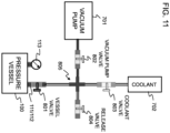
- a valve 801 is provided at the coolant inlet 112.
- Open/close valves 801-804 and pipe arrangement 805 can be used to selectively communicate among the pressure vessel 100, a vacuum pump 701, a coolant tank 702 and the outside.
- weight measurement is performed in a state in which the pressure vessel 100 is emptied, that is, contains no coolant. Subsequently, in a state in which the coolant valve 803 and the release valve 804 are closed and the vessel valve 801 is opened, the vacuum pump 701 evacuates the pressure vessel 100 while monitoring the pressure in the pressure vessel.
- the vacuum pump valve 802 When the evacuation is complete, the vacuum pump valve 802 is closed. Then, the coolant valve 803 is opened to pour coolant from the coolant tank 702 into the pressure vessel 100. Subsequently, the coolant valve 803 and the vessel valve 801 are closed and the release valve 804 is opened, thereby discharging coolant existing in the pipe arrangement 805. In this way, the amount of coolant contained in the pressure vessel 100 is estimated by weight measurement of the pressure vessel 100. If necessary, the vessel valve 801 is opened to discharge coolant from the pressure vessel 100 while monitoring the measured weight of the pressure vessel 100. The inner pressure of the pressure vessel 100 can be adjusted to fall into a predetermined range by connecting to the vacuum pump 701 and monitoring the pressure sensor.
- the pressure vessel 100 is connected to the thermal control system 200 as shown in Fig. 1 , and the pump 203 is driven to circulate the coolant to cool the circuit board 141 while performing thermal control by the thermal control system 200.
- the invention is applicable to immersion cooling apparatuses used in harsh environments such as extremely cold/hot regions and the outer space.
Landscapes
- Engineering & Computer Science (AREA)
- Microelectronics & Electronic Packaging (AREA)
- Physics & Mathematics (AREA)
- Thermal Sciences (AREA)
- Computer Hardware Design (AREA)
- General Engineering & Computer Science (AREA)
- Cooling Or The Like Of Electrical Apparatus (AREA)
- Cooling Or The Like Of Semiconductors Or Solid State Devices (AREA)
Abstract
An immersion cooling apparatus includes a pressure vessel including a vessel body and at least one lid. The at least one lid is detachably joined to the vessel body, wherein a certain lid of the at least one lid has a coolant outlet and a coolant inlet. The pressure vessel is filled with liquid coolant. A mounting member places the circuit board at a position between the coolant outlet and the coolant inlet within the pressure vessel. The circuit board is immersed in the liquid coolant within the pressure vessel such the circuit board is surrounded with the liquid coolant. The liquid coolant forcedly flows from one side of the circuit board to outside through the coolant outlet and forcedly flows into the other side of the circuit board from outside through the coolant inlet.
Description
- The present application relates to techniques for cooling electronic equipment that generates heat.
- Recent electronic equipment includes a lot of semiconductor circuits, and in particular, integrated circuits such as central processing units (CPUs) or processors are essential electronic components for performing various controls of electronic devices. Usually, consumer-oriented electronic components are not designed for use in harsh environments. Accordingly, ruggedizing techniques are indispensable in the case where the electronic equipment is expected to be used in environments outside normal ranges of temperature, pressure, vibration, etc.
- As an example of a ruggedizing technique,
JP2002-166899 - On the other hand, many electronic components include semiconductor circuits (e.g., processors) that generate heat during operation. In the case where such heat-generating electronic components are sealed within a container, it is necessary to provide a means of dissipating heat to outside. For example, electronic equipment mounted on an artificial satellite includes circuit boards containing integrated circuits that perform high-speed calculations with high heat generation. Accordingly, not only ruggedizing but also cooling is an indispensable technique.
- The above-mentioned Patent Document 1 discloses a structure in which a cooling plate is provided on the bottom plate of a container to conduct heat generated by electronic components to the outside for heat exhaustion. Also,
JP H07-025395 - In recent years, immersion cooling, in which the electronic device itself is immersed in a coolant bath, has attracted attention as a method for cooling electronic devices such as computers. For example, in
JP Patent No. 6720752 U.S. Patent No. 9750159B2 - List of Related-art documents:
- [Patent document 1]
JP2002-166899 - [Patent document 2]
JP H07-025395 - [Patent document 3]
JP Patent No. 6720752 - [Patent document 4]
U.S. Patent No. 9750159B2 - According to the heat dissipation methods disclosed in Patent documents 1 and 2, it is difficult to achieve high dissipation efficiency of heat because the heat from integrated circuits is dissipated by means of thermal conduction through multiple components.
- According to the immersion cooling devices described in Patent documents 3 and 4, different coolant flowing means are required: a means of flowing a first coolant in which the electronic equipment is immersed; and another means of flowing a second coolant for cooling that first coolant, which results in complicated structure and manufacturing process.
- The immersion cooling devices described in Patent documents 3 and 4 employ a cooling system designed for normal use on the ground. In other words, they are not designed for use in harsh environment such as zero-gravity environment and extreme conditions of substantial vibrations when launched by a rocket. Therefore, when such an immersion cooling device is mounted on a spacecraft as it is, the convection of the coolant does not occur in weightless space, and bubbles due to boiling do not remove from heat dissipation fins, causing dry-out phenomenon.
- An object of the present invention is to provide an immersion cooling device which allows enhanced resistance to harsh environment, increased cooling efficiency, and easy design and manufacturing.
- According to an embodiment of the present invention, an immersion cooling apparatus for a circuit board including a heat-generating section, includes: a pressure vessel including a vessel body and at least one lid, wherein the at least one lid is detachably joined to the vessel body, wherein a certain lid of the at least one lid has a coolant outlet and a coolant inlet, wherein the pressure vessel is filled with liquid coolant; and a mounting member that places the circuit board at a position between the coolant outlet and the coolant inlet within the pressure vessel, wherein the circuit board is immersed in the liquid coolant within the pressure vessel such the circuit board is surrounded with the liquid coolant, wherein the liquid coolant forcedly flows from one side of the circuit board to outside the pressure vessel through the coolant outlet and forcedly flows into the other side of the circuit board from outside the pressure vessel through the coolant inlet.
- According to the invention, the circuit board is immersed in the liquid coolant and securely placed in the pressure vessel with the liquid coolant forcedly flowing along the circuit board. This enhances resistance to harsh environments and improves cooling efficiency. Further the coolant outlet and coolant inlet are provided on one lid of the pressure vessel, resulting in simplified design and manufacturing.
-
-
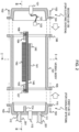
Fig. 1 illustrates a schematic side cross-sectional view of an immersion cooling apparatus according to a first exemplary embodiment of the present invention. -
Fig. 2 illustrates an exploded side sectional view of a pressure vessel of the immersion cooling apparatus according to the first embodiment. -
Fig. 3 illustrates a cross-sectional view taken along lines I-I ofFig. 2 . -
Fig. 4 illustrates a cross-sectional view taken along lines II-II lines ofFig. 2 . -
Fig. 5 illustrates an exploded perspective view of an example of a pressure vessel of the immersion cooling apparatus according to the first embodiment. -
Fig. 6 illustrates a schematic cross-sectional view of an example of a pressure vessel mounted with a slot card in the immersion cooling apparatus according to the first embodiment. -
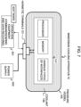
Fig. 7 illustrates a schematic block diagram of connection between the circuit board within the pressure vessel and the external electrical system in the immersion cooling apparatus according to the first embodiment. -
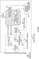
Fig. 8 illustrates a schematic block diagram for explaining the overall configuration and operation of the immersion cooling apparatus according to the first embodiment. -
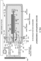
Fig. 9 illustrates a schematic side cross-sectional view of an immersion cooling apparatus according to a second embodiment of the present invention. -
Fig. 10 illustrates an exploded side cross-sectional view for explaining the structure of the pressure vessel of the immersion cooling apparatus according to the second embodiment. -
Fig. 11 illustrates a schematic diagram of a coolant filling arrangement for filling a pressure vessel with coolant. - According to an embodiment of the present invention, a pressure vessel composed of at least one detachable lid and a vessel body is filled with a coolant, and a circuit board is placed and immersed in the coolant within the pressure vessel. One lid has a coolant inlet and a coolant outlet, through which the coolant is forced to circulate. Furthermore, both ends of the circuit board are secured by mounting members provided in the vessel body.
- The coolant flows into the pressure vessel from the coolant inlet by means of a forced-liquid flow generator installed outside the pressure vessel. The coolant flows into the pressure vessel through the coolant inlet, flows over the front and back surfaces of the circuit board, and flows out through the coolant outlet. More specifically, the coolant inlet and the coolant outlet are provided in the same lid, and the coolant flows in through the coolant inlet, flows on one side of the circuit board, flows along the inner surface of the pressure vessel to the other side of the circuit board, and flows out through the coolant outlet. Accordingly, the space around the circuit board is filled with flowing coolant, allowing efficient cooling. In addition, the circuit board is immersed in the coolant and surrounded by the pressure vessel, and both ends of the circuit board are secured by mounting members within the pressure vessel, allowing enhanced resistance to harsh environment. In particular, the circuit board has excellent resistance to harsh environments such as extremely cold/hot regions and the outer space, as well as environments subjected to substantial vibrations during rocket launches or the like.
- In an assembly process, the electronic circuit board can be easily installed in the pressure vessel by simply detaching the lid from the vessel body, placing the electronic circuit board in the vessel body, and then joining the lid and the vessel body. Preferably, the pressure vessel is divided into three sections: the vessel body having openings on both opposite surfaces; and a pair of lids each covering the openings of the vessel body. One of the lids is provided with the coolant inlet and the coolant outlet, and the other is provided with electrical terminals. By employing such division structure, the mechanical design of the pressure vessel, the design of the electrical system including the electronic circuit board and electrical terminals, and the design of coolant thermal control system can be separated, allowing improved design efficiency.
- Furthermore, according to the exemplary embodiment, the coolant inlet and the coolant outlet are provided on one lid, allowing the thermal control system including the heat dissipation mechanism and the forced-liquid flow generator such as a pump to be arranged on the side of the one lid. As a result, the coolant that flows out through the coolant outlet of the pressure vessel is cooled by the thermal control system and then returned to the pressure vessel through the coolant inlet, to form a circulation system. Since the coolant on the electronic circuit board is forced to flow by the forced-liquid flow generator, the heat generated on the electronic circuit board can be dissipated to outside, thereby efficiently cooling the electronic circuit board. Accordingly, t the dry-out phenomenon can be prevented from occurring on the electronic circuit even in a space where gravity can be ignored.
- Exemplary embodiments of the present invention will be described in detail below with reference to the drawings. It should be noted that the components, their shapes, dimensions and dimension ratios, and arrangements described in the following embodiments are just examples for explaining the embodiments and are not intended to limit the technical scope of the invention to them.
- As illustrated in
Figs. 1 to 4 , an immersion cooling apparatus 10 according to a first embodiment of the present invention comprises apressure vessel 100 and athermal control system 200. Thepressure vessel 100 comprises acylindrical vessel body 101 and first andsecond lids second lids vessel body 101, respectively. Thepressure vessel 100 seals incoolant 130. Thefirst lid 110 and thesecond lid 120 are hermetically joined to the opening surfaces on both sides of thevessel body 101 by a plurality ofbolts 102 or other joining members. Here, it is assumed that thefirst lid 110 is used for the coolant system and thesecond lid 120 for the electrical system. - The
vessel body 101 is provided with a mounting member composed of mountingflanges vessel body 101. The mountingflanges plate 140 as described below. Thevessel body 101 hasflanges vessel body 101. Theseflanges first lid 110 and thesecond lid 120 to thevessel body 101. - The
first lid 110 has acoolant outlet 111 and acoolant inlet 112. Thecoolant 130 flows out through thecoolant outlet 111.Coolant 130 that has been temperature-controlled by thethermal control system 200 flows in through thecoolant inlet 112. Furthermore,sensors 113 for detecting the pressure and temperature in thepressure vessel 100 are provided at a position closer to thecoolant outlet 111 between thecoolant outlet 111 and thecoolant inlet 112. Thefirst lid 110 also has aflange 114 protruding inward at a position between the pressure andtemperature sensors 113 and thecoolant inlet 112 such that theflange 114 comes into contact with the mountingflange 103 of thevessel body 101. Theflange 114 and the mountingflange 103 are combined to form a partition wall that partitions the inside of thepressure vessel 100 on the side of thefirst lid 110 vertically (in the top-and-bottom direction ofFig. 1 ) as shown inFigs. 1 and3 . Accordingly, theflange 114 and the mountingflange 103 as the partition wall prevents thecoolant 130 from directly flowing from thecoolant inlet 112 to the pressure andtemperature sensors 113 and thecoolant outlet 111. Thefirst lid 110 has aflange 115 protruding outward from the opening end of thefirst lid 110. Theflange 115 is used to join thefirst lid 110 to theflange 105 of thevessel body 101 by joining members 102 (seeFig. 2 ). - The
second lid 120 hashermetic terminals 121 at the approximately central portion of thesecond lid 120. Thehermetic terminals 121 are electrical terminals for sending and receiving signals to and from the outside and for receiving power supply. Thehermetic terminals 121 are connected to aconnector 123 through acable 122 in thecoolant 103 and theconnector 123 is connected to aconnector 142 mounted on acircuit board 141. Thesecond lid 120 has aflange 124 protruding outward from the opening end of thesecond lid 120. Theflange 124 is used to join thesecond lid 120 to theflange 106 of thevessel body 101 by joining members 102 (seeFig. 2 ). - Inside the
pressure vessel 100, theplate 140 is supported and secured at both ends thereof by the mountingflanges circuit board 141 is fixed to the surface of theplate 140 on the side of thecoolant outlet 111. Heat-dissipatingfins 143 are fixed to the surface of theplate 140 on the side of thecoolant inlet 112. Aconnector 142 is provided at the end of thecircuit board 141 on the side of thesecond lid 120. As described above, theconnector 142 is connected to thehermetic terminals 121 through theconnector 123 and thecable 122, allowing signal transmission and power supply between thecircuit board 141 and the outside. - The
thermal control system 200 includes a pipe arrangement connecting thecoolant outlet 111 and thecoolant inlet 112; avalve 202 provided near thecoolant outlet 111; apump 203 which is a forced-liquid flow generator located near thecoolant inlet 112; anaccumulator 204 with heating means; and aradiator plate 205 coupled to thepipe arrangement 201 by radiation. Thepump 203 drives the coolant 13 in thepressure vessel 100 to flow from thecoolant outlet 111 to thevalve 202 and thepipe arrangement 201. The heat of the coolant flowing through thepipe arrangement 201 is dissipated into outside by theradiator plate 205. (seeFig. 1 ). - The
pump 203 drives the coolant thus cooled to flow into thepressure vessel 100 through thecoolant inlet 112. The cooled coolant flows over the heat-dissipatingfins 143 and thecircuit board 141 to cool them. Even if heat of the heat-dissipatingfins 143 and thecircuit board 141 causescoolant 130 to vaporize to generate bubbles BB, thepump 203 forcedly flows the bubbles BB flow together with thecoolant 130 and then the bubbles BB condense near the inner wall of thepressure vessel 100. In this way, thecoolant 130 circulates through the interior of thepressure vessel 100 and thepipe arrangement 201 of thethermal control system 200 between thecoolant outlet 111 and thecoolant inlet 112. Theaccumulator 204 is a vessel which is equipped with a heater inside and temporarily stores gas/liquid. Accordingly, the heater in theaccumulator 204 can be controlled to adjust the pressure and temperature of thecoolant 130 to a state suitable for phase change (vaporization and condensation). - As illustrated in
Fig. 2 , theplate 140 mounted with thecircuit board 141 and the heat-dissipatingfins 143 is fixed on the mountingflanges vessel body 101 bytap bolts Fig. 4 , the mountingflanges tap bolts tap bolts plate 140 to the mountingflanges tap bolts circuit board 141 on theplate 140 is fixed and placed in the near central portion of thevessel body 101. - As illustrated in
Fig. 1 , thepressure vessel 100 andthermal control system 200 described above are fixed to amount panel 300 of a satellite or the like by supportinglegs pipe arrangement 201, thepump 203, theaccumulator 204 and theradiator plate 205 of thethermal control system 200 are also supported and secured to themount panel 300 by support members (not shown) to prevent them from coming off due to vibrations or the like. -
Fig. 5 illustrates an appearance of thepressure vessel 100 more specifically. InFig. 5 , the similar components as inFigs. 1-4 are labeled with the same reference numbers. - As illustrated in
Fig. 6 , a slot card 144 can be mounted on thecircuit board 141 withspacers 145 such that the slot card 144 is connected to thecircuit board 141 through an immersion-dedicatedcable 146 and aconnector 147. Since the slot card 144 is mounted parallel to thecircuit board 141 as shown inFig. 6 , the performance of a processor and other devices can be expanded without increasing the diameter of thevessel body 101. In addition, cooling efficiency can be maintained because the flow ofcoolant 130 is not impeded. - Also, by using the immersion-dedicated
cable 146, thecircuit board 141 and expansion slot cards can be arranged flexibly in thepressure vessel 100. More specifically, although expansion slot cards are usually mounted perpendicular to the circuit board, it is possible to mount the expansion slot cards parallel to thecircuit board 141, allowing thepressure vessel 100 to be downsized without unnecessarily widening its diameter. - As illustrated in
Fig. 7 , the processor and other components on thecircuit board 141 are connected tooperation equipment 501 and apower supply 502 provided outside thepressure vessel 100 through thehermetic terminals 121. Theoperation equipment 501 can send commands to operate thecircuit board 141 by software and receive response data accordingly. Thepower supply 502 supplies power to thecircuit board 141. - Referring to
Fig. 8 , the functional configuration of the immersion cooling apparatus 10 will be described, assuming that the immersion cooling apparatus 10 is mounted on a satellite which is an example of a space vehicle. Here, it is also assumed that thedriver system 600 controls thepump 203 and theaccumulator 204 of the thermal control system 20 under the control of thecircuit board 141. - In
Fig. 8 , theoperation equipment 501 inputs the pressure of thepressure vessel 100 and the temperature of the coolant from the pressure andtemperature sensors 113 and sends operating commands including the pressure and temperature data to thecircuit board 141. The processor on thecircuit board 141 sends control data of thedriver system 600 to thedriver system 600 through theoperation equipment 501 according to the pressure and temperature data to adjust the pressure of thepressure vessel 100 and the temperature of the coolant. More specifically, while monitoring the detection data from the pressure andtemperature sensors 113, thepump 203 is driven and the heater temperature of theaccumulator 204 is adjusted to control the temperature of thecoolant 130 to a temperature suitable for phase change (vaporization and condensation). - The
coolant 130 should be an electrically insulating and thermally conductive liquid, preferably containing hydrogen atoms for neutron beam moderation and shielding. For example, a liquid such as CFC (chlorofluorocarbons)-replacing material or polyester can be used assuch coolant 130. In the present embodiment, when the temperature of theentire pressure vessel 100 is controlled at 60°C or lower, the boiling point of thecoolant 130 is about 76°C. - As described above, according to the first exemplary embodiment, the
circuit board 141 is immersed in thecoolant 130 flowing through thepressure vessel 100, which allows for efficient cooling. Thecircuit board 141 is surrounded by thepressure vessel 100 and thecoolant 130, enhancing the resistance to substantial vibrations and harsh environments such as the outer space. - According to the present exemplary embodiment, the
pressure vessel 100 can be divided into three sections: thevessel body 101; the first lid (for coolant system); and the second lid (for electrical systems). Since one of the first and second lids is used for the coolant system and the other for the electrical system, the design of the mechanical structure of thepressure vessel 100, the design of the thermal control system, and the design of the electrical system can be divided respectively, making it easier to derive the optimal solution for the immersion cooling apparatus 10. Specifically, it is possible to divide the design of the immersion cooling apparatus 10 into three sections as follows: the mechanical design section responsible for theentire pressure vessel 100 and each mechanical joint; the thermal control design section responsible for installation of thepipe arrangement 201, thepump 203 and theaccumulator 204; and the electrical design section responsible for thehermetic terminals 121 on the side of thesecond lid 120 and thecircuit board 141. - For the support rigidity of the
circuit board 141 mounted in thepressure vessel 100, thevessel body 101 is provided with the mountingflanges vessel body 101, respectively. The mountingflanges circuit board 141. Theplate 140 mounted with thecircuit board 141 is fixed on the mountingflanges plate 140. This ensures the support rigidity that meets resistance requirements to substantial vibrations such as during rocket launches. - In the present exemplary embodiment, the
first lid 110 for the coolant system and thesecond lid 120 for the electrical system are provided on both sides of thevessel body 101. However, the present embodiment is not limited to such a structure. If mounting is not difficult, thefirst lid 110 and thesecond lid 120 may be placed adjacent to each other. - In the first embodiment described above, two separate lids are provided for the coolant system and the electrical system, respectively. However, the present invention is not limited to such a structure. An immersion cooling apparatus in which a single lid is shared for both coolant and electrical systems may obtain advantageous effects similar to those in the first embodiment. More specifically, the surrounding space of the electronic circuit board placed in the pressure vessel is filled with flowing coolant, allowing efficient cooling. Also, the electronic circuit board is surrounded by the pressure vessel and the coolant, allowing enhanced resistance to harsh environments such as substantial vibrations and the outer space. In addition, the detachable lid can be removed to facilitate circuit board installation.
- As a second embodiment of the present invention, an immersion cooling apparatus in which a single lid is shared for both coolant and electrical systems is described below with reference to
Figs. 9 and10 . For simplifying explanation, the same components as in the first embodiment are labeled with the same reference numerals. - As illustrated in
Figs. 9 and10 , an immersion cooling apparatus 40 according to the second embodiment of the invention comprises apressure vessel 400 and athermal control system 200. Thepressure vessel 400 comprises acylindrical vessel body 401 with only one opening and adetachable lid 410 provided at the opening of thevessel body 401. Thepressure vessel 400 seals incoolant 430. Thelid 410 is hermetically joined to thevessel body 401 by a plurality ofbolts 402 or other joining members. - The opening of the
vessel body 401 has aflange 403 protruding outward from the opening end of thevessel body 101. Theflange 403 is used to join thelid 410 to thevessel body 101. Asupport member 404 having aslot 405 is provided inside thevessel body 401 such that aplate 440 described below is supported at one end thereof by the end portion of theplate 440 fitting into theslot 405 of thesupport member 404. - The
lid 410 has acoolant outlet 411 and acoolant inlet 412. Thecoolant 130 flows out through thecoolant outlet 411.Coolant 130 that has been temperature-controlled by thethermal control system 200 flows in through thecoolant inlet 412. Furthermore,sensors 413 for detecting the pressure and temperature in thepressure vessel 400 are provided at a position closer to thecoolant outlet 411 between thecoolant outlet 411 and thecoolant inlet 412. Thelid 410 hashermetic terminals 421 at the approximately central portion of thelid 410. Thehermetic terminals 421 are electrical terminals for sending and receiving signals to and from the outside and for receiving power supply. Thehermetic terminals 421 are connected to aconnector 423 through acable 422 in thecoolant 430 and theconnector 423 is connected to aconnector 442 mounted on acircuit board 441. - The
lid 410 also has aflange 414 protruding inward at a position between the pressure andtemperature sensors 413 and thecoolant inlet 412 such that theplate 440 is supported by thesupport member 404 at one end of theplate 440 and is fixed by theflange 414 at the other end of theplate 440. Theflange 414 and theplate 440 are combined to form a partition wall that partitions the inside of thepressure vessel 400 on the side of thelid 410 vertically (in the top-and-bottom direction ofFig. 9 ). Accordingly, theflange 414 and theplate 440 as the partition wall prevents thecoolant 430 from directly flowing from thecoolant inlet 412 to the pressure andtemperature sensors 413 and thecoolant outlet 411. Thelid 410 has aflange 415 protruding outward from the opening end of thelid 410. Theflange 415 is used to join thelid 410 to theflange 403 of thevessel body 401 by joining members 402 (seeFig. 10 ). - As described above, the
plate 440 is supported and fixed at both ends in thepressure vessel 400 by thesupport member 404 and theflange 414. Thecircuit board 441 is fixed to the surface of theplate 440 on the side of thecoolant outlet 411. Heat-dissipatingfins 443 are fixed to the surface of theplate 440 on the side of thecoolant inlet 412. Theconnector 442 is provided at the end of thecircuit board 441 on the side of thelid 410. As described above, theconnector 442 is connected to thehermetic terminals 421 through theconnector 423 and thecable 422, allowing signal transmission and power supply between thecircuit board 441 and the outside. - The
thermal control system 200 has apipe arrangement 201 joined with thecoolant outlet 411 and thecoolant inlet 412. Since thethermal control system 200 has the same structure and functions as those of the first exemplary embodiment shown inFig. 1 , similar members and components are denoted by the same reference numerals and their explanations will be omitted. - As illustrated in
Fig. 10 , theplate 440 is fixed at one end to the mountingflange 414 oflid 410 bytap bolts 416. The mountingflange 414 has clearance holes through which thetap bolts 416 pass, allowing for visual inspection when tightening thetap bolts 416 to mount theplate 440 to the mountingflange 414, and facilitating work when attaching thetap bolts 416. In this way, theplate 440 mounted with thecircuit board 441 and theheat dissipating fins 443 can be fixed to the mountingflange 414 of thelid 410 at one end of theplate 440. - In an assembly process, the
circuit board 441 and theheat dissipating fins 443 are fixed on theplate 440 and then theplate 440 is fixed to the mountingflange 414 of thelid 410 at one end of theplate 440. Subsequently, as shown inFig. 10 , thevessel body 401 is moved in the direction shown by an arrow to accommodate theplate 440 mounted with thecircuit board 441 and theheat dissipating fins 443. At that time, theplate 440 fits in theslot 405 of thesupport member 404 at the other end of theplate 440, so that theplate 440 is secured at both ends of theplate 440 in thepressure vessel 400. Finally, the joiningmember 402 is used to hermetically join thevessel body 401 to thelid 410 and then thecoolant 430 is introduced into thepressure vessel 400. Note that guide members (not shown) may be provided at regular intervals on the inner side wall of thevessel body 401 so that theplate 440 is guided toward theslot 405 of thesupport member 404 and is finally inserted into theslot 405. - As described above, according to the present embodiment, the
circuit board 441 is immersed in thecoolant 430 flowing through thepressure vessel 400, which allows for efficient cooling. Thecircuit board 441 is surrounded by thepressure vessel 400 and thecoolant 430, enhancing the resistance to substantial vibrations and harsh environments such as the outer space. - In the present embodiment, the
pressure vessel 400 has thevessel body 401 and thelid 410 which can be separated. With thelid 410 removed, theplate 440 mounted with thecircuit board 441 can be easily attached to the mountingflange 414 of thelid 410. Subsequently, thevessel body 401 is joined with thelid 410 so that theplate 440 mounted with thecircuit board 441 is inserted into thevessel body 401. In this way, thecircuit board 441 is sealed in thepressure vessel 400. - For the support rigidity of the
circuit board 441 mounted in thepressure vessel 400, theplate 440 mounted with the circuit board 41 is fixed at both ends by thesupport member 404 of thevessel body 401 and the mountingflange 414 of thelid 410, respectively. This ensures the support rigidity that meets resistance requirements to substantial vibrations such as during rocket launches. - In the first and second exemplary embodiments as described above, after the pressure vessel (100, 400) has been assembled, the pressure vessel must be filled with coolant. The filling procedure of the coolant will be described below, taking the
pressure vessel 100 in the first exemplary embodiment as an example. The same filling procedure may be used for thepressure vessel 400 in the second exemplary embodiment. - In
Fig. 11 , thevalve 202 at thecoolant outlet 111 of thepressure vessel 100 is closed. Avalve 801 is provided at thecoolant inlet 112. Open/close valves 801-804 andpipe arrangement 805 can be used to selectively communicate among thepressure vessel 100, avacuum pump 701, acoolant tank 702 and the outside. - First, weight measurement is performed in a state in which the
pressure vessel 100 is emptied, that is, contains no coolant. Subsequently, in a state in which thecoolant valve 803 and therelease valve 804 are closed and thevessel valve 801 is opened, thevacuum pump 701 evacuates thepressure vessel 100 while monitoring the pressure in the pressure vessel. - When the evacuation is complete, the
vacuum pump valve 802 is closed. Then, thecoolant valve 803 is opened to pour coolant from thecoolant tank 702 into thepressure vessel 100. Subsequently, thecoolant valve 803 and thevessel valve 801 are closed and therelease valve 804 is opened, thereby discharging coolant existing in thepipe arrangement 805. In this way, the amount of coolant contained in thepressure vessel 100 is estimated by weight measurement of thepressure vessel 100. If necessary, thevessel valve 801 is opened to discharge coolant from thepressure vessel 100 while monitoring the measured weight of thepressure vessel 100. The inner pressure of thepressure vessel 100 can be adjusted to fall into a predetermined range by connecting to thevacuum pump 701 and monitoring the pressure sensor. - When the coolant filling and the pressure adjustment are completed, the
pressure vessel 100 is connected to thethermal control system 200 as shown inFig. 1 , and thepump 203 is driven to circulate the coolant to cool thecircuit board 141 while performing thermal control by thethermal control system 200. - The invention is not limited to the exemplary embodiments described above, but can be modified in various ways without departing from the spirit or essential characteristics of the invention.
- The invention is applicable to immersion cooling apparatuses used in harsh environments such as extremely cold/hot regions and the outer space.
Claims (13)
- An immersion cooling apparatus for a circuit board including a heat-generating section, characterized by comprising:a pressure vessel including a vessel body and at least one lid, wherein the at least one lid is detachably joined to the vessel body, wherein a certain lid of the at least one lid has a coolant outlet and a coolant inlet, wherein the pressure vessel is filled with liquid coolant; anda mounting member that places the circuit board at a position between the coolant outlet and the coolant inlet within the pressure vessel, wherein the circuit board is immersed in the liquid coolant within the pressure vessel such the circuit board is surrounded with the liquid coolant,wherein the liquid coolant forcedly flows from one side of the circuit board to outside the pressure vessel through the coolant outlet and forcedly flows into the other side of the circuit board from outside the pressure vessel through the coolant inlet.
- The immersion cooling apparatus according to claim 1, further comprising
a thermal control system that exchanges heat with liquid coolant flowing out of the coolant outlet and flows heat-exchanged liquid coolant into the coolant inlet, wherein the thermal control system includes a forced-liquid flow generator. - The immersion cooling apparatus according to claim 1 or 2, wherein the mounting member includes a first mounting member and a second mounting member which support the circuit board at both end portions thereof.
- The immersion cooling apparatus according to claim 3, the vessel body has the first mounting member and the second mounting member.
- The immersion cooling apparatus according to claim 3, wherein the vessel body has the first mounting member and the certain lid has the second mounting member.
- The immersion cooling apparatus according to claim 1 or 2, wherein the vessel body has two opening surfaces which are detachably closed by a first lid and a second lid, respectively, wherein the first lid has the coolant outlet and the coolant inlet, and the second lid has electric terminals connected to the circuit board.
- The immersion cooling apparatus according to claim 6, wherein the vessel body is of cylindrical shape and has the two opening surfaces opposing to each other.
- The immersion cooling apparatus according to claim 6, wherein the mounting member comprises: a first mounting member protruding outward from one of the two opening surfaces; and a second mounting member protruding outward from the other of the two opening surfaces,
wherein the circuit board is fixed to the first mounting member and the second mounting member. - The immersion cooling apparatus according to claim 8, wherein the first lid has a protruding wall on an inner wall of the first lid at a position between the coolant outlet and the coolant inlet, wherein the protruding wall and the first mounting member are combined to form a partition wall that partitions first-lid-side inside space of the pressure vessel such that the partition wall prevents the liquid coolant from directly flowing from the coolant inlet to the coolant outlet.
- The immersion cooling apparatus according to claim 1 or 2, wherein the vessel body has a single opening surface which is detachably closed by a single lid, wherein the single lid has the coolant outlet, the coolant inlet and electric terminals connected to the circuit board.
- A space vehicle equipped with the immersion cooling apparatus according to any one of claims 1-10.
- A method for cooling a circuit board including a heat-generating section, wherein the circuit board is placed within a pressure vessel, wherein the at least one lid is detachably joined to the vessel body, wherein the circuit board is immersed in liquid coolant within the pressure vessel such the circuit board is surrounded with the liquid coolant, the method characterized by comprising:preparing a certain lid of the at least one lid having a coolant outlet and a coolant inlet;forcedly flowing the liquid coolant from one side of the circuit board to outside the pressure vessel through the coolant outlet; andforcedly flowing the liquid coolant into the other side of the circuit board from outside the pressure vessel through the coolant inlet.
- The method according to claim 12, further comprising
exchanging heat with the liquid coolant forcedly flowing out of the coolant outlet and forcedly flows heat-exchanged liquid coolant into the coolant inlet.
Applications Claiming Priority (1)
| Application Number | Priority Date | Filing Date | Title |
|---|---|---|---|
| JP2022037302A JP7838326B2 (en) | 2022-03-10 | 2022-03-10 | liquid immersion cooling device |
Publications (1)
| Publication Number | Publication Date |
|---|---|
| EP4243584A1 true EP4243584A1 (en) | 2023-09-13 |
Family
ID=82458394
Family Applications (1)
| Application Number | Title | Priority Date | Filing Date |
|---|---|---|---|
| EP22175962.4A Pending EP4243584A1 (en) | 2022-03-10 | 2022-05-28 | Immersion cooling apparatus |
Country Status (4)
| Country | Link |
|---|---|
| US (2) | US12171082B2 (en) |
| EP (1) | EP4243584A1 (en) |
| JP (1) | JP7838326B2 (en) |
| CN (1) | CN116782583A (en) |
Families Citing this family (2)
| Publication number | Priority date | Publication date | Assignee | Title |
|---|---|---|---|---|
| US12402272B2 (en) * | 2021-01-12 | 2025-08-26 | Cooler Master Co., Ltd. | Single-phase immersion cooling system and method of the same |
| US20240130075A1 (en) * | 2022-10-18 | 2024-04-18 | Schlumberger Technology Corporation | High reliability, low cost electronics in oil for subsea applications |
Citations (10)
| Publication number | Priority date | Publication date | Assignee | Title |
|---|---|---|---|---|
| JPH0420752B2 (en) | 1982-09-22 | 1992-04-06 | Ansuchi* Seratsuku Sa | |
| JPH0725395B2 (en) | 1988-04-14 | 1995-03-22 | 株式会社タツノ・メカトロニクス | Oil changer |
| JP2002166899A (en) | 2000-11-30 | 2002-06-11 | Mitsubishi Electric Corp | Space environment resistant container |
| SE1400472A1 (en) * | 2014-10-10 | 2014-10-14 | Abb Technology Ltd | Subsea aluminum heat exchanger |
| EP2928275A1 (en) * | 2014-04-04 | 2015-10-07 | ABB Technology Ltd | Arrangement for cooling components of a subsea electric system |
| US20160257433A1 (en) * | 2015-03-03 | 2016-09-08 | York Space Systems LLC | Mission agnostic space vehicle |
| US9750159B2 (en) | 2013-10-21 | 2017-08-29 | International Business Machines Corporation | Pump-enhanced, immersion-cooling of electronic compnent(s) |
| US20180153059A1 (en) * | 2016-11-30 | 2018-05-31 | Data Marine, LLC | Data vessel integrated with cooling and docking station with ancillary service |
| US20180199465A1 (en) * | 2017-01-06 | 2018-07-12 | Hamilton Sundstrand Corporation | Immersion cooling arrangements |
| US20190219311A1 (en) * | 2012-09-07 | 2019-07-18 | David Lane Smith | Cooling electronic devices installed in a subsurface environment |
Family Cites Families (19)
| Publication number | Priority date | Publication date | Assignee | Title |
|---|---|---|---|---|
| US3909678A (en) * | 1974-04-19 | 1975-09-30 | Ibm | Packaging structure for a plurality of wafer type integrated circuit elements |
| JPS57201031U (en) * | 1981-06-16 | 1982-12-21 | ||
| US4730665A (en) * | 1983-07-14 | 1988-03-15 | Technology Enterprises Company | Apparatus for cooling high-density integrated circuit packages |
| US4700272A (en) * | 1986-06-26 | 1987-10-13 | Digital Equipment Corporation | Apparatus and method for compensation of thermal expansion of cooling fluid in enclosed electronic packages |
| JPH0595064A (en) * | 1991-10-01 | 1993-04-16 | Hitachi Ltd | Semiconductor cooling device |
| JP2518140B2 (en) | 1993-07-12 | 1996-07-24 | 日本電気株式会社 | Heat dissipation device for satellite mounted equipment |
| US6304447B1 (en) * | 1998-12-31 | 2001-10-16 | Lucent Technologies, Inc. | Arrangement for cooling an electrical assembly |
| JP2001237581A (en) | 2000-02-24 | 2001-08-31 | Toshiba Corp | Heating element cooling device |
| US8369090B2 (en) * | 2009-05-12 | 2013-02-05 | Iceotope Limited | Cooled electronic system |
| US20120314373A1 (en) * | 2010-02-11 | 2012-12-13 | Brian Park | Seabed Pressure Bottle Thermal Management |
| JP2012016095A (en) | 2010-06-29 | 2012-01-19 | Denso Corp | Electric power conversion device |
| JP2013187251A (en) | 2012-03-06 | 2013-09-19 | Sohki:Kk | Cooling system and method of electronic apparatus |
| US20150354902A1 (en) * | 2013-01-10 | 2015-12-10 | Woods Hole Oceanographic Institution | Thermal transfer system |
| JP6720752B2 (en) | 2016-07-25 | 2020-07-08 | 富士通株式会社 | Immersion cooling device, immersion cooling system, and method of controlling immersion cooling device |
| US11058029B2 (en) * | 2017-05-11 | 2021-07-06 | Exascaler Inc. | Liquid immersion-cooled electronic device and liquid immersion-cooled processor module |
| US11343944B2 (en) * | 2017-12-01 | 2022-05-24 | Raytheon Company | Deep-water submersible system |
| US10204659B1 (en) * | 2018-04-14 | 2019-02-12 | Microsoft Technology Licensing, Llc | Hard disk drive backplane for immersion-cooled circuit board |
| US10165707B1 (en) * | 2018-04-27 | 2018-12-25 | Northrop Grumman Systems Corporation | Device and method for providing immersion cooling in a compact-format circuit card environment |
| CN212727814U (en) | 2020-07-17 | 2021-03-16 | 建准电机工业股份有限公司 | Immersion cooling device |
-
2022
- 2022-03-10 JP JP2022037302A patent/JP7838326B2/en active Active
- 2022-05-19 US US17/748,207 patent/US12171082B2/en active Active
- 2022-05-28 EP EP22175962.4A patent/EP4243584A1/en active Pending
- 2022-06-07 CN CN202210638591.XA patent/CN116782583A/en active Pending
-
2024
- 2024-10-28 US US18/928,241 patent/US20250056758A1/en active Pending
Patent Citations (10)
| Publication number | Priority date | Publication date | Assignee | Title |
|---|---|---|---|---|
| JPH0420752B2 (en) | 1982-09-22 | 1992-04-06 | Ansuchi* Seratsuku Sa | |
| JPH0725395B2 (en) | 1988-04-14 | 1995-03-22 | 株式会社タツノ・メカトロニクス | Oil changer |
| JP2002166899A (en) | 2000-11-30 | 2002-06-11 | Mitsubishi Electric Corp | Space environment resistant container |
| US20190219311A1 (en) * | 2012-09-07 | 2019-07-18 | David Lane Smith | Cooling electronic devices installed in a subsurface environment |
| US9750159B2 (en) | 2013-10-21 | 2017-08-29 | International Business Machines Corporation | Pump-enhanced, immersion-cooling of electronic compnent(s) |
| EP2928275A1 (en) * | 2014-04-04 | 2015-10-07 | ABB Technology Ltd | Arrangement for cooling components of a subsea electric system |
| SE1400472A1 (en) * | 2014-10-10 | 2014-10-14 | Abb Technology Ltd | Subsea aluminum heat exchanger |
| US20160257433A1 (en) * | 2015-03-03 | 2016-09-08 | York Space Systems LLC | Mission agnostic space vehicle |
| US20180153059A1 (en) * | 2016-11-30 | 2018-05-31 | Data Marine, LLC | Data vessel integrated with cooling and docking station with ancillary service |
| US20180199465A1 (en) * | 2017-01-06 | 2018-07-12 | Hamilton Sundstrand Corporation | Immersion cooling arrangements |
Also Published As
| Publication number | Publication date |
|---|---|
| JP2023132139A (en) | 2023-09-22 |
| JP7838326B2 (en) | 2026-04-01 |
| US20250056758A1 (en) | 2025-02-13 |
| US12171082B2 (en) | 2024-12-17 |
| US20230292460A1 (en) | 2023-09-14 |
| CN116782583A (en) | 2023-09-19 |
Similar Documents
| Publication | Publication Date | Title |
|---|---|---|
| US20250056758A1 (en) | Immersion cooling apparatus | |
| EP4068929B1 (en) | A rack system for housing an electronic device | |
| US10206308B2 (en) | Module for cooling a heat generating component | |
| CN111095541B (en) | Heat sink, heat sink device and module for liquid immersion cooling | |
| JP4859823B2 (en) | COOLING DEVICE AND ELECTRONIC DEVICE USING THE SAME | |
| US6661664B2 (en) | Electronic module with high cooling power | |
| US5305184A (en) | Method and apparatus for immersion cooling or an electronic board | |
| US7131484B2 (en) | Modular architecture for thermal control in a spacecraft | |
| US20150208551A1 (en) | Apparatuses for Transmitting Heat Between a Rail of Rack Mounted Equipment and a Channel of a Cooling Rack Enclosure, And Related Components, Systems, and Methods | |
| WO2003024177A1 (en) | Electronic apparatus | |
| GB2467805A (en) | Sealable module for cooling electrical components | |
| EP0274263A2 (en) | Cryostat and cryogenically cooled computer system | |
| CN102138374B (en) | Aircraft signal computer system having a plurality of modular signal computer units | |
| US6691766B1 (en) | Cabinet cooling with heat pipe | |
| CN114846915A (en) | Cooling module | |
| EP4363324B1 (en) | Improved system for thermal regulation of a spacecraft | |
| BR112016029109B1 (en) | SUBSEA COOLING ASSEMBLY | |
| CN105722373B (en) | Method and device for cooling equipment provided with electronic board by using different fluid cooling boards | |
| US20260021910A1 (en) | Ruggedizing Apparatus and Method for Electronic Equipment Mounted on Spacecraft | |
| EP3206470A1 (en) | Frame for holding an electronic board, housing, and rack including frame and housing | |
| US20190363410A1 (en) | Externally-cooled battery housing | |
| CN214199799U (en) | Heat dissipation assembly for cabin and spacecraft | |
| CN110381702A (en) | Electronic equipment | |
| JP2024027599A (en) | Liquid immersion cooling network system for spacecraft and its control method | |
| US20240431070A1 (en) | Server cooling with immersed heat sink |
Legal Events
| Date | Code | Title | Description |
|---|---|---|---|
| PUAI | Public reference made under article 153(3) epc to a published international application that has entered the european phase |
Free format text: ORIGINAL CODE: 0009012 |
|
| STAA | Information on the status of an ep patent application or granted ep patent |
Free format text: STATUS: REQUEST FOR EXAMINATION WAS MADE |
|
| 17P | Request for examination filed |
Effective date: 20230623 |
|
| AK | Designated contracting states |
Kind code of ref document: A1 Designated state(s): AL AT BE BG CH CY CZ DE DK EE ES FI FR GB GR HR HU IE IS IT LI LT LU LV MC MK MT NL NO PL PT RO RS SE SI SK SM TR |
|
| STAA | Information on the status of an ep patent application or granted ep patent |
Free format text: STATUS: EXAMINATION IS IN PROGRESS |
|
| 17Q | First examination report despatched |
Effective date: 20250331 |