EP4243352A1 - Collective switching from a differential signalling communication mode to a single-ended communication mode upon the detection of a fault - Google Patents
Collective switching from a differential signalling communication mode to a single-ended communication mode upon the detection of a fault Download PDFInfo
- Publication number
- EP4243352A1 EP4243352A1 EP22161031.4A EP22161031A EP4243352A1 EP 4243352 A1 EP4243352 A1 EP 4243352A1 EP 22161031 A EP22161031 A EP 22161031A EP 4243352 A1 EP4243352 A1 EP 4243352A1
- Authority
- EP
- European Patent Office
- Prior art keywords
- bus
- voltage
- signal
- communication
- signalling
- Prior art date
- Legal status (The legal status is an assumption and is not a legal conclusion. Google has not performed a legal analysis and makes no representation as to the accuracy of the status listed.)
- Pending
Links
- 238000004891 communication Methods 0.000 title claims abstract description 156
- 230000011664 signaling Effects 0.000 title claims abstract description 105
- 238000001514 detection method Methods 0.000 title claims abstract description 51
- 230000004044 response Effects 0.000 claims description 24
- 238000000034 method Methods 0.000 claims description 21
- 230000005540 biological transmission Effects 0.000 claims description 12
- 239000000725 suspension Substances 0.000 claims description 3
- 230000008859 change Effects 0.000 description 4
- 229910000679 solder Inorganic materials 0.000 description 4
- 230000001360 synchronised effect Effects 0.000 description 3
- 230000001052 transient effect Effects 0.000 description 3
- 230000007704 transition Effects 0.000 description 3
- 230000008878 coupling Effects 0.000 description 2
- 238000010168 coupling process Methods 0.000 description 2
- 238000005859 coupling reaction Methods 0.000 description 2
- 238000004519 manufacturing process Methods 0.000 description 2
- 239000000463 material Substances 0.000 description 2
- 238000012986 modification Methods 0.000 description 2
- 230000004048 modification Effects 0.000 description 2
- 239000000872 buffer Substances 0.000 description 1
- 238000007796 conventional method Methods 0.000 description 1
- 238000002405 diagnostic procedure Methods 0.000 description 1
- 238000010586 diagram Methods 0.000 description 1
- 239000000446 fuel Substances 0.000 description 1
- 238000010438 heat treatment Methods 0.000 description 1
- 230000008520 organization Effects 0.000 description 1
- 230000002688 persistence Effects 0.000 description 1
- 230000008569 process Effects 0.000 description 1
- 238000012545 processing Methods 0.000 description 1
- 230000001105 regulatory effect Effects 0.000 description 1
- 238000009423 ventilation Methods 0.000 description 1
- XLYOFNOQVPJJNP-UHFFFAOYSA-N water Substances O XLYOFNOQVPJJNP-UHFFFAOYSA-N 0.000 description 1
Images


Classifications
-
- H—ELECTRICITY
- H04—ELECTRIC COMMUNICATION TECHNIQUE
- H04L—TRANSMISSION OF DIGITAL INFORMATION, e.g. TELEGRAPHIC COMMUNICATION
- H04L12/00—Data switching networks
- H04L12/28—Data switching networks characterised by path configuration, e.g. LAN [Local Area Networks] or WAN [Wide Area Networks]
- H04L12/40—Bus networks
- H04L12/40169—Flexible bus arrangements
-
- H—ELECTRICITY
- H04—ELECTRIC COMMUNICATION TECHNIQUE
- H04L—TRANSMISSION OF DIGITAL INFORMATION, e.g. TELEGRAPHIC COMMUNICATION
- H04L41/00—Arrangements for maintenance, administration or management of data switching networks, e.g. of packet switching networks
- H04L41/06—Management of faults, events, alarms or notifications
- H04L41/0654—Management of faults, events, alarms or notifications using network fault recovery
-
- H—ELECTRICITY
- H04—ELECTRIC COMMUNICATION TECHNIQUE
- H04L—TRANSMISSION OF DIGITAL INFORMATION, e.g. TELEGRAPHIC COMMUNICATION
- H04L12/00—Data switching networks
- H04L12/28—Data switching networks characterised by path configuration, e.g. LAN [Local Area Networks] or WAN [Wide Area Networks]
- H04L12/40—Bus networks
- H04L2012/40208—Bus networks characterized by the use of a particular bus standard
- H04L2012/40215—Controller Area Network CAN
Definitions
- the present disclosure relates to apparatus for providing a reconfiguration signal.
- apparatus for providing a reconfiguration signal to other nodes coupled to a communication bus to provide for collective switching to a single-ended communication mode.
- second apparatus configured to receive the reconfiguration signal and a method of operating a first apparatus and at least one second apparatus.
- In-vehicle network (IVN) buses such as CAN (Controller Area Network), CAN FD (CAN with Flexible Data-Rate), LIN (Local Interconnect Network), FlexRay, Ethernet based network buses, and other types, can be used for communications within vehicles.
- CAN Controller Area Network
- CAN FD CAN with Flexible Data-Rate
- LIN Local Interconnect Network
- FlexRay Ethernet based network buses
- CAN controller area network
- CAN controller area network
- CAN is a message-based communications bus protocol that is often used within automobiles. It will be appreciated that CAN networks also have application outside of the field of automobiles.
- a CAN bus network may include multiple bus devices, so called nodes or electronic control units (ECUs), such as an engine control module (ECM), a power train control module (PCM), airbags, antilock brakes, cruise control, electric power steering, audio systems, windows, doors, mirror adjustment, battery and recharging systems for hybrid/electric cars, and many more.
- ECUs electronice control units
- the CAN bus protocol is used to enable communications between the various bus devices.
- the data link layer of the CAN protocol is standardized as International Standards Organization (ISO) 11898-1:2003.
- ISO International Standards Organization
- CAN Flexible Data-Rate or "CAN FD” which is an extension of the standardized CAN data link layer protocol and is meanwhile integrated into the IS011898-1:2015 standard, can provide higher data rates.
- CAN XL A further extension, referred to as CAN XL, with a new level scheme allowing even higher data rates is in the definition phase discussed under CiA610 (CAN in Automation) and is moving towards standardization in the form of either a further update of the existing IS011898 standards or a new standard.
- an apparatus comprising:
- said apparatus comprises a Controller Area Network, CAN, transceiver.
- the apparatus is configured to provide a differential communication mode in which the transceiver arrangement is configured to transmit and receive the differential signalling, and a single-ended communication mode in which the transceiver arrangement is configured to transmit via a single one of the first terminal and the second terminal relative to a reference voltage; and wherein the apparatus is configured to switch from the differential communication mode to the single-ended communication mode in response to said fault detection signal.
- the fault detection device is configured to detect faults in one or more of the communication bus and the one or more network nodes and, in response to detection of a fault, generate the fault detection signal.
- the reconfiguration signal includes at least a first part and a temporally subsequent part, wherein the first part is configured to communicate the occurrence of the fault to the one or more network nodes and to cause the suspension of the transmission of differential signalling over the communication bus by the one or more network nodes; and the subsequent part is configured to communicate the start of the period of single-ended communication.
- said fault detection signal is indicative of a fault comprising at least one of a physical break in one of said first and second bus wires of the communication bus and a break in the one or more connections between the apparatus and the communication bus.
- the fault detection signal is an internal signal to the apparatus and is not provided to said communication bus.
- the fault detection signal has at least a first signal form and a different, second signal form
- the first signal form and the second signal form differ in terms of one or both of:
- the apparatus is configured to receive a first voltage from a first voltage source and a second voltage, greater than the first voltage, from a second voltage source, wherein said differential signalling provided by the transceiver arrangement is provided with reference to the first voltage and wherein the high-voltage-level is based on the second voltage.
- the reconfiguration signal is provided for transmission via the one of the first bus wire and second bus wire that does not have the fault indicated by the fault detection signal.
- the apparatus is configured to: based on receipt of the reconfiguration signal from said one or more network nodes, provide for switching from use, by said transceiver arrangement, of differential signalling to single-ended signalling using only one of said first bus wire and said second bus wire.
- the reconfiguration signal does not have the part that has the high-voltage-level and is identifiable to the other network nodes by a different feature thereof.
- a second apparatus comprising:
- said second apparatus comprises a Controller Area Network, CAN, transceiver.
- the reconfiguration signal includes at least a first part and a temporally subsequent part, wherein the first part is configured to communicate the occurrence of the fault to the one or more network nodes and to cause the suspension, by the second apparatus, of the transmission of differential signalling over the communication bus; and the subsequent part is configured to communicate the start of the period of single-ended communication.
- the second apparatus is configured to:
- a third aspect of the disclosure we provide a method performed by a first apparatus configured to couple to a first bus wire and a second bus wire of a communication bus and at least one second apparatus configured to couple to the first bus wire and the second bus wire of the communication bus, the first apparatus and the second apparatus each comprising a transceiver arrangement for communicating with one another via the communication bus, each transceiver arrangement configured to provide differential signalling to the first and second bus wires according to a communication scheme and receive differential signalling from the first and second bus wires according to the communication scheme, wherein the communication scheme defines at least the voltage to be used to provide said differential signalling; wherein the method comprises:
- the method comprises receiving, by the second apparatuses, the reconfiguration signal and collectively switching, by the second apparatuses in response to said receiving of the reconfiguration signal, from transmitting and receiving of the differential signalling to transmitting and receiving single-ended signalling using only one of said first bus wire and the second bus wire.
- said step of transmitting the reconfiguration signal comprises:
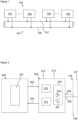
- Example Figure 1 shows a communication bus based network 100 with a plurality of nodes 101-104 coupled to a common communication bus.
- the bus system 100 comprises a Controller Area Network, CAN, in this example.
- the plurality of nodes or ECUs (Electronic Control Units) 101-104 are connected to the same CAN bus wires 105 comprising a first wire 106, known as CANH, and a second wire 107, known as CANL.
- the nodes 101-104 may comprise nodes that implement Classical CAN, CAN FD nodes that implement the CAN FD protocol or CAN XL nodes that implement the new CAN XL protocol.
- a node mainly comprises a CAN controller 200, such as a microcontroller, that implements the CAN, CAN FD or CAN XL protocol such as by using an embedded CAN, CAN FD or CAN XL protocol controller 201.
- the CAN controller 200 may be known as a host.
- the controller 200 and, more particularly, the protocol controller 201 is connected to the CAN bus 105 via a CAN transceiver 202.
- the CAN controller 200 is connected to the CAN transceiver 202 through two interface connections called TXD (Transmit Data) 203 and RXD (Receive Data) 204.
- the controller may therefore have a transmit output terminal that couples with a transmit input terminal of the CAN transceiver 202.
- the CAN transceiver 202 may have a receive output terminal that couples with a receive input terminal of the CAN controller 200.
- the examples described below relate to an apparatus that, in one or more examples, may comprise the CAN transceiver 202. However, it will be appreciated that the functionality of the apparatus described may be provided at least in part by the CAN transceiver 202. It will also be appreciated that while the example embodiments are described in the context of CAN, the apparatus may have wider application to other bus based networks.
- the apparatus or transceiver 202 includes a transceiver arrangement 205 configured to generate differential signalling at the first terminal 208 and the second terminal 209 according to a communication scheme, i.e. the CAN protocol in this example.
- the transceiver arrangement 205 is also configured to receive differential signalling from the first terminal 208 and second terminal 209 from the communication bus 105 according to the communication scheme.
- the communication scheme defines one or more details of the voltage, timing and encoding of the signals that are to be transmitted on and received from the bus 107.
- the communication scheme defines at least the voltage to be used to provide said differential signalling.
- the transceiver arrangement 205 may be configured to convert transmit data, comprising a digital bit stream on TXD 203, into analogue, differential, signalling on the bus wires 105 using a transmitter module 206.
- the transceiver arrangement 205 may also be used to convert analogue signalling from the bus 105 into receive data comprising a digital output signal or bit stream by a receiver module 207 for providing to the RXD connection 204.
- the transmitter module 206 is thus configured to convert the transmit data into dominant bit and recessive bit differential signals for the bus 105.
- the receiver module 207 is thus configured to receive the differential signals from the bus 105 and determine the presence of either a dominant bit or a recessive bit and generate the receive data based thereon.
- the transceiver 202 comprises a first terminal 208 configured to couple the transceiver 202 to a first bus wire 106 of the communication bus 105 and a second terminal 209 configured to couple the transceiver 202 to the second bus wire 107 of the communication bus 105.
- the CAN transceiver 202 and the transceiver arrangement 205 thereof comprises an interface device to the network bus and the CAN controller comprises a controller that is configured to transmit data to and receive data from the network via the interface device.
- the CAN transceiver 202 is known as such because it has the purpose of acting as a transceiver for the CAN controller 200 and, as mentioned, the transceiver arrangement 205 provides this functionality. However, it will be appreciated by those skilled in the art that current CAN transceivers 202 may comprise other functionality in addition to the transceiver arrangement 205, as will be described in more detail later.
- Figure 3 shows an example of the differential signals on the bus 105.
- the axis 301 shows voltage of the CANH and CANL wires 106, 107.
- the axis 302 shows time.
- a recessive bit (representing logic "1") is present on the bus 105.
- the voltage level of CANH and CANL are both at ⁇ 2.5V such that there is no differential signal between the CANH and CANL wires.
- a transceiver 202 of one of the nodes 101-104 drives the CANH wire 106 to a high voltage level 305 and the CANL wire 107 to a low voltage level 306 such that a differential voltage signal 307 between the CANH and CANL wires, referred to as a dominant voltage (representing logic "0"), is provided.
- the high voltage level at 305 is typically around 3.5 V, while the low voltage level at 306 is typically around 1.5 V.
- the CAN protocol or, more generally, the communication scheme defines the use of these voltages to represent the data transmitted and received from the bus 105.
- Errors or physical faults can occur in the CAN bus system 100 that can disrupt communication.
- a fault may occur in the transceiver 202 or the communication bus 105.
- the fault may prevent transmission or receipt of signals over one of the CANH 106 and CANL 107 wires.
- the other of the CANH 106 and CANL 107 wires may not have a fault.
- the nodes 101-104 it is known for the nodes 101-104 to be configured to change to communicating by transmitting and receiving signals using the single, fault-free, bus wire 106, 107 of the bus 105 when a fault occurs that prevents the use of the usual differential signals, shown in example Figure 3 .
- a transition to the intended single-ended communication mode can be difficult.
- the communication mode for that one node is changed to single-ended communication, which means communication takes place on one of the CANH and CANL wires 106, 107.
- a difficulty may be present in that all nodes should similarly and independently identify the occurrence of the faults and thereby switch to the single-ended communication mode or the change in communication mode needs to be reliably detected by all other nodes 101-104 in the network. It is not easy to ensure that under all possible failures, in any network topology, that all nodes 101-104 always detect the change in the communication mode reliably and transition accordingly to the intended single-ended communication mode at the same time.
- the apparatus 202 or, in this example, the CAN transceiver 202 is configured to act in response to a fault detection signal from a fault determination device 210.
- the fault detection device 210 is part of the apparatus 202 but that need not be the case.
- the apparatus 202 is configured to receive the fault detection signal from a different apparatus, such as the controller 200.
- the fault detection signal is a signal that is internal to the apparatus 202 or internal to the node 101-104 of which the apparatus 202 forms part. Accordingly, it may not be a signal that is provided to or received from the communication bus 105.
- the fault detection signal is indicative of the occurrence of a fault in at least the communication bus 105 and one or more connections, including terminals 208 and 209 between the apparatus 202 and the communication bus 105.
- the operation of the fault determination device 210 is not the focus of this application and it may use conventional methods to determine when a fault occurs.
- the fault detection device 210 may be configured to detect faults in one or more of the communication bus, the electrical connections that couple the apparatus 202 to the bus 105, the electrical connection(s) that couple that apparatus to the controller 200 and the electrical connection(s) in one or more network nodes 101-104.
- the possible faults that may have occurred to cause the generation of the fault detection signal are described below. However, the occurrence of the fault, whichever way it is detected, is signalled to the apparatus 202 by the fault detection signal.
- a fault in the supply of power to the transceiver 202 there may be one or more of a fault in the supply of power to the transceiver 202; a fault in an internal bias current in the transceiver 202; a fault in circuitry of the transmitter module 205; a fault in the circuitry of the receiver module 206; or a fault in the input/output buffers to the microcontroller 200, 201.
- there may be a fault in the wiring harness that is the unshielded twisted pair of wires comprising CANH 106 and CANL 107.
- a fault in the wiring harness there may be one or more of an: open wire or intermittent open wire on CANH or CANL; open connection contact or intermittent open connection contact at CANH or CANL; open solder joint contact or intermittent open solder joint contact at CANH or CANL; open or intermittently open solder joint contact at transmit-output terminal to TXD or receive-input from RXD at the microcontroller 200; and open or intermittently open solder joint contact at a transmit-input terminal from TXD 203 or receive-output terminal to RXD 204 at the transceiver 202.
- the fault detection signal may be indicative of a fault comprising at least one of a physical break in one of said first and second bus wires 106, 107 of the communication bus 105 and a break in the one or more connections between the apparatus 202 and the communication bus 105.
- the apparatus 202 in response to the fault detection signal, is configured to transmit a reconfiguration signal for said one or more other network nodes 101-104 coupled to the communication bus 105.
- the reconfiguration signal may be intended for all nodes coupled to the bus 105.
- the reconfiguration signal may be intended for all nodes coupled to the bus 105 that have the functionality or circuitry configured to detect it.
- the reconfiguration signal is provided for transmission via at least one of said first terminal 208 and said second terminal 209.
- the reconfiguration signal may be provided to both terminals 208 or 209, i.e. the same signal transmitted to both terminals.
- the reconfiguration signal is provided for transmission via the one of the first bus wire 106 and the second bus wire 107 that does not have the fault indicated by the fault detection signal.
- the fault detection signal may be indicative of which of the first bus wire 105 and the second bus wire 106 has been affected by the fault or which bus wire 106, 107 is in working order.
- the apparatus 202 may be configured to use that information to transmit the reconfiguration signal via the first or the second terminal 208, 209 such that it is conveyed by the working bus wire 106, 107.
- the reconfiguration signal is distinguishable by the one or more nodes 101-104 from the differential signalling normally present on the bus 105 by one or more signal properties that differ from those defined in the communication scheme or protocol for the differential signalling.
- the CAN protocol defines the bit time and the voltages to provide to the bus wires 106, 107.
- at least part of the reconfiguration signal has a high-voltage-level comprising a voltage higher than that defined in the communication scheme for said differential signalling, which may make the reconfiguration signal readily identifiable by detection circuitry of the one or more nodes 101-104.
- the communication scheme may define one or more voltages to be present on the first bus wire 106 or CANH as part of generation of the differential signalling.
- the high-voltage-level of the reconfiguration signal may be higher than the highest of those one or more voltages defined for the first bus wire 106 or CANH.
- the communication scheme may define one or more voltages to be present on the second bus wire 107 or CANL as part of generation of the differential signalling.
- the high-voltage-level of the reconfiguration signal may be higher than the highest of those one or more voltages defined for the second bus wire 107 or CANL.
- the reconfiguration signal is configured to cause the one or more network nodes to provide for switching from use of differential signalling to single-ended signalling using only one of the first bus wire 106 and the second bus wire 107.
- the reconfiguration signal may provide an instruction that achieves the synchronized switching of the signalling method of the nodes to provide a transition between a bus system 100 that uses differential signalling to one that uses single-ended signalling. It will be appreciated that by “synchronized” we mean not strictly at exactly the same time but sufficiently close in time that subsequent single-ended communication will be received successfully by all of the nodes 101-104 that react to the reconfiguration signal.
- the use of the reconfiguration signal may, in one or more examples, provide for improved network reliability.
- the reconfiguration signal may be configured to achieve other actions at the one or more other nodes 101-104.
- the generation of the reconfiguration signal is provided by a reconfiguration module 211 of the apparatus 202.
- the reconfiguration module 211 may be configured to control the transceiver arrangement 205 to cause it to transmit the reconfiguration signal to the bus 105, as required.
- Each node 101-104 including the apparatus 202, may thus provide a differential communication mode in which the transceiver arrangement 205 is configured to transmit and receive the differential signalling, and a single-ended communication mode in which the transceiver arrangement 205 is configured to transmit via a single one (the one without the fault) of the first terminal 208 and the second terminal 209 relative to a reference voltage, such as ground.
- the apparatus 202 or reconfiguration module 211 thereof may thus be configured to switch from the differential communication mode to the single-ended communication mode in response to said fault detection signal.
- the reconfiguration module 211 may be configured to provide corresponding signalling to the transceiver arrangement 205 to cause the change in the communication mode.
- Example figure 4 summarizes the operation of the apparatus 202 or the fault detection module 211 thereof.
- Step 401 represents the apparatus 202 being configured to transmit signalling and/or receive signalling in the differential communication mode, which may comprise the default mode for such an apparatus 202.
- Step 402 comprises a decision block which comprises determining if the fault detection signal has been received, which may be considered equivalent to detecting if a fault has occurred. If the answer is "no” then the method returns to step 401. If the answer is "yes” then the method proceeds to step 403, which comprises transmitting the reconfiguration signal to all other nodes coupled to the communication bus 105, at least via the working bus wire 106, 107.
- Step 404 represents the nodes 101-104 (i.e. all those nodes other than the node that sent the reconfiguration signal) reconfiguring themselves to adopt the single-ended communication mode. Communication between the nodes 101-104 may then continue with the nodes collectively in the single-ended communication mode.
- the reconfiguration signal may be configured to prompt the other nodes coupled to the communication bus 105 to switch to single-ended communication mode but it may be left to the other nodes (or transceivers 202 thereof) to determine which of the bus wires 106, 107 to use in said single-ended communication mode.
- the reconfiguration signal may contain information that signals to the other nodes 101-104 which of the bus wires 106, 107 to use in said single-ended communication mode.
- Figures 5 and 6 show two examples of the form of the reconfiguration signal.
- Example figure 5 shows the reconfiguration signal having a first signal form 501.
- Example figure 6 shows the reconfiguration signal having a different, second signal form 601.
- the nodes 101-104 that receive the reconfiguration signal (or, more particularly, the transceivers 202 thereof) may be informed of which of the bus wires to use for the single-ended communication.
- the first signal form 501 may be configured to cause the one or more network nodes 101-104 to reconfigure to a single-ended signalling mode using only said first bus wire 106.
- the second signal form 601 may be configured to cause the one or more network nodes to reconfigure to use a single-ended signalling mode using only said second bus wire 107.
- the signal forms are for example only and they could signal the use of the other bus wire in other embodiments to that set out above.
- Examples figure 5 and 6 show the voltage of the reconfiguration signal on the vertical axis and time on the horizontal axis.
- the reconfiguration signal of the first form 501 comprises a first period 502 in which the apparatus 202 provides the reconfiguration signal having a high-voltage-level 503.
- the first period 502 may comprise 25 microseconds, as an example only.
- the reconfiguration signal is provided with a lower, positive second voltage 505.
- the second period 504 may comprise 35 microseconds, as an example only.
- the reconfiguration signal is provided at the high-voltage-level 503 once again.
- the third period 506 may comprise 20 microseconds, as an example only.
- the reconfiguration signal of the second form 601 comprises a first period 602 in which the apparatus 202 provides the reconfiguration signal having the high-voltage-level 603, same as voltage level 503.
- the first period 602 may comprise 15 microseconds, as an example only.
- the first period 602 is shorter than the first period 502.
- the duration for which the reconfiguration signal 601 is at said high-voltage-level 603 may comprise the only distinguishing feature between the first and second forms 501, 601 or may be one of a plurality of distinguishing features.
- the reconfiguration signal 601 is provided with a lower, positive second voltage 605, which in this example is the same as the second voltage 505.
- the second period 604 may comprise 45 microseconds, as an example only. Thus, the second period 604 is longer than the second period 504.
- the duration for which the reconfiguration signal 601 is at said second voltage 605 may comprise a distinguishing feature of the second form 601 of the reconfiguration signal.
- the reconfiguration signal 601 is provided at the high-voltage-level 603 once again.
- the third period 606 may comprise 20 microseconds, as an example only. In this and other examples, the duration of the third period 506, 606 may be the same in both signal forms 501, 601.
- the signal forms comprise a "header" 502, 504 and 602, 604 that differ in form and convey the information about which bus wire 106, 107 to use in the single-ended communication mode.
- headers may differ in terms of the duration 502, 602 for which the reconfiguration signal is at said high-voltage-level 503, 603.
- the headers may differ in terms of the duration for which the reconfiguration signal is at a lower voltage level than said high-level-voltage 503, 603 between the first period 502, 602 at the high-level-voltage and the third period 506, 606 at the high-voltage-level 503, 603.
- the signal forms 501, 601 further comprise a final part 506, 606 provided to allow time for the individual nodes 101-104 in the network to reconfigure to the desired communication method. It may thereby be ensured that at the end of the reconfiguration signal (the end of the third period 506, 606), all nodes 101-104 are synchronized and reconfigured to the single-ended communication mode.
- the first part or period 502, 602 is configured to communicate the occurrence of the fault to the one or more other nodes .
- the other nodes in response to the receipt of the first part 502, 602, may be configured to suspend differential signalling. It will be appreciated that the apparatus may also suspend transmission of differential signalling.
- the second part 504, 604 may comprise a delay before implementation of the single-ended communication.
- the one or more nodes may be configured to use the delay to perform one or more diagnostic tests and/or to provide time to switch to the single-ended communication mode.
- the third part 506, 606 may communicate the start of the period of single-ended communication.
- the nodes 101-104 may therefore be configured to begin single-ended communication at a corresponding time, in response to the receipt of the third part 506, 606.
- the high-voltage-level 503, 603 and second voltage level 505, 605 may be based on supply voltage levels provided to the apparatus 202.
- the apparatus 202 typically receives power at two voltage levels.
- a first power-input terminal 212 is configured to receive a first voltage from a first voltage source.
- the first voltage source may comprise a regulated voltage input at, for example 5 V.
- a second power-input terminal 213 is configured to receive a second voltage, greater than the first voltage, from a second voltage source.
- the second voltage source may comprise the vehicle's 12 V battery.
- the differential signalling provided by the transceiver arrangement 205 may be provided with reference to the first voltage and wherein the high-voltage-level is based on or comprises the second voltage, e.g. 12 V.
- the apparatus 202 may receive power at a single power input terminal and may include a power converter to provide the different voltage levels required for the reconfiguration signal.
- the apparatus 202 may be configured to detect receipt of the reconfiguration signal from any of the other nodes 101-104 (or, more particularly, from apparatuses similar to apparatus 202 of those other nodes).
- the apparatus 202 may include reconfiguration signal detection circuitry, which may be part of module 211.
- the reconfiguration signal detection circuitry may comprise a comparator (not shown) configured to trigger upon receipt of a voltage above a predetermined threshold that would be exceeded by the high-voltage-level 503, 603 rather than the normal differential signalling.
- the reconfiguration signal detection circuitry may include a timer (not shown) for determining the duration of one or more time periods 502, 602, 504, 604 based on the occurrence or persistence of the high-voltage-level 503, 603. The determination made by the timer may determine the bus wire used by the nodes 101-104 in the single-ended communication mode.
- the apparatus 202 may, based on the receipt of the reconfiguration signal from said one or more network nodes 101-104, provide for switching from use, by said transceiver arrangement 205, of differential signalling to single-ended signalling using only one of said first bus wire 106 and second bus wire 107.
- the first apparatus may comprise the transceiver 202 of one of the nodes 101-104.
- the second apparatus may comprise the transceiver 202 of a different one of the nodes 101-104.
- the first apparatus and the second apparatus each comprising a transceiver 202 for communicating with one another via the communication bus 105.
- Each transceiver 202 may be configured to provide differential signalling to the first and second bus wires according to the communication scheme and receive differential signalling from the first and second bus wires according to the communication scheme, wherein the communication scheme defines at least the voltage to be used to provide said differential signalling.
- the method comprises:
- the reconfiguration signal is provided for all nodes on the communication bus 105.
- the method step 703 and 704 comprise receiving, by the second apparatuses, the reconfiguration signal and collectively switching, by the second apparatuses in response to said receiving of the reconfiguration signal, from transmitting and receiving of the differential signalling to transmitting and receiving single-ended signalling using only one of said first bus wire and the second bus wire.
- the transmitting step 702 may comprises:
- the apparatus 202 and the bus based system 100 of which it forms part may have application in a variety of contexts.
- the system may comprise an Antilock Braking System (ABS), an Electronic Power Steering (EPS) system, or a Heating Ventilation and Air Control (HVAC) system.
- ABS Antilock Braking System
- EPS Electronic Power Steering
- HVAC Heating Ventilation and Air Control
- the apparatus 202 may also be applied in body controllers, fuel Pumps, water pumps or oil pumps.
- the system may comprise an automotive based system or a nonautomotive based system.
- the apparatus 202 is disclosed in the context of a CAN based network, the provision of the reconfiguration signal in response to the fault determination signal by the apparatus 202 may have application in other network types, such as LIN (Local Interconnect Network), FlexRay, or Ethernet based network buses.
- LIN Local Interconnect Network
- FlexRay FlexRay
- Ethernet Ethernet based network buses.
- the set of instructions/method steps described above are implemented as functional and software instructions embodied as a set of executable instructions which are effected on a computer or machine which is programmed with and controlled by said executable instructions. Such instructions are loaded for execution on a processor (such as one or more CPUs).
- processor includes microprocessors, microcontrollers, processor modules or subsystems (including one or more microprocessors or microcontrollers), or other control or computing devices.
- a processor can refer to a single component or to plural components.
- the set of instructions/methods illustrated herein and data and instructions associated therewith are stored in respective storage devices, which are implemented as one or more non-transient machine or computerreadable or computer-usable storage media or mediums.
- Such computerreadable or computer usable storage medium or media is (are) considered to be part of an article (or article of manufacture).
- An article or article of manufacture can refer to any manufactured single component or multiple components.
- the non-transient machine or computer usable media or mediums as defined herein excludes signals, but such media or mediums may be capable of receiving and processing information from signals and/or other transient mediums.
- Example embodiments of the material discussed in this specification can be implemented in whole or in part through network, computer, or data based devices and/or services. These may include cloud, internet, intranet, mobile, desktop, processor, look-up table, microcontroller, consumer equipment, infrastructure, or other enabling devices and services. As may be used herein and in the claims, the following non-exclusive definitions are provided.
- one or more instructions or steps discussed herein are automated.
- the terms automated or automatically mean controlled operation of an apparatus, system, and/or process using computers and/or mechanical/electrical devices without the necessity of human intervention, observation, effort and/or decision.
- any components said to be coupled may be coupled or connected either directly or indirectly.
- additional components may be located between the two components that are said to be coupled.
Abstract
Description
- The present disclosure relates to apparatus for providing a reconfiguration signal. In particular, it relates to an apparatus for providing a reconfiguration signal to other nodes coupled to a communication bus to provide for collective switching to a single-ended communication mode. It also relates to a second apparatus configured to receive the reconfiguration signal and a method of operating a first apparatus and at least one second apparatus.
- In-vehicle network (IVN) buses, such as CAN (Controller Area Network), CAN FD (CAN with Flexible Data-Rate), LIN (Local Interconnect Network), FlexRay, Ethernet based network buses, and other types, can be used for communications within vehicles. For example, controller area network (CAN) bus is a message-based communications bus protocol that is often used within automobiles. It will be appreciated that CAN networks also have application outside of the field of automobiles. A CAN bus network may include multiple bus devices, so called nodes or electronic control units (ECUs), such as an engine control module (ECM), a power train control module (PCM), airbags, antilock brakes, cruise control, electric power steering, audio systems, windows, doors, mirror adjustment, battery and recharging systems for hybrid/electric cars, and many more. The CAN bus protocol is used to enable communications between the various bus devices. The data link layer of the CAN protocol is standardized as International Standards Organization (ISO) 11898-1:2003. CAN Flexible Data-Rate or "CAN FD," which is an extension of the standardized CAN data link layer protocol and is meanwhile integrated into the IS011898-1:2015 standard, can provide higher data rates. The standardized CAN data link layer protocol is being further extended to provide even higher data rates. A further extension, referred to as CAN XL, with a new level scheme allowing even higher data rates is in the definition phase discussed under CiA610 (CAN in Automation) and is moving towards standardization in the form of either a further update of the existing IS011898 standards or a new standard.
- According to a first aspect of the present disclosure there is provided an apparatus comprising:
- at least a first terminal configured to couple the apparatus to a first bus wire of a communication bus and a second terminal configured to couple the apparatus to a second bus wire of the communication bus;
- a transceiver arrangement for communicating with one or more network nodes via the communication bus, the transceiver arrangement configured to provide differential signalling at the first terminal and the second terminal according to a communication scheme and receive differential signalling from the first terminal and second terminal from the communication bus according to the communication scheme, wherein the communication scheme defines at least a voltage to be used to provide said differential signalling;
- the apparatus configured to:
- based on a fault detection signal from a fault determination device, the fault detection signal indicative of the occurrence of a fault in at least one of the communication bus and one or more connections between the apparatus and the communication bus, transmit a reconfiguration signal, wherein the reconfiguration signal is provided for transmission via at least one of said first terminal and said second terminal for said one or more network nodes and wherein at least part of the reconfiguration signal has a high-voltage-level comprising a voltage higher than that defined in the communication scheme for said differential signalling; and
- wherein said reconfiguration signal is configured to cause the one or more network nodes to provide for switching from use of differential signalling to single-ended signalling using only one of the first bus wire and the second bus wire.
- In one or more embodiments, said apparatus comprises a Controller Area Network, CAN, transceiver.
- In one or more embodiments, the apparatus is configured to provide a differential communication mode in which the transceiver arrangement is configured to transmit and receive the differential signalling, and a single-ended communication mode in which the transceiver arrangement is configured to transmit via a single one of the first terminal and the second terminal relative to a reference voltage; and
wherein the apparatus is configured to switch from the differential communication mode to the single-ended communication mode in response to said fault detection signal. - In one or more embodiments, one or both of:
- the apparatus includes the fault detection device; and
- the apparatus is configured to receive the fault detection signal from a different apparatus.
- In one or more examples, the fault detection device is configured to detect faults in one or more of the communication bus and the one or more network nodes and, in response to detection of a fault, generate the fault detection signal.
- In one or more embodiments, the reconfiguration signal includes at least a first part and a temporally subsequent part, wherein the first part is configured to communicate the occurrence of the fault to the one or more network nodes and to cause the suspension of the transmission of differential signalling over the communication bus by the one or more network nodes; and
the subsequent part is configured to communicate the start of the period of single-ended communication. - In one or more examples, said fault detection signal is indicative of a fault comprising at least one of a physical break in one of said first and second bus wires of the communication bus and a break in the one or more connections between the apparatus and the communication bus.
- In one or more examples, the fault detection signal is an internal signal to the apparatus and is not provided to said communication bus.
- In one or more embodiments, the fault detection signal has at least a first signal form and a different, second signal form; and
- wherein the first signal form is configured to cause the one or more network nodes to reconfigure to single-ended signalling using only said first bus wire; and
- wherein the second signal form is configured to cause the one or more network nodes to reconfigure to single-ended signalling using only said second bus wire.
- In one or more embodiments, the first signal form and the second signal form differ in terms of one or both of:
- a) the duration for which the reconfiguration signal is at said high-voltage-level;
- b) the duration for which the reconfiguration signal is at a lower voltage level than said high-level-voltage between a first period at the high-level-voltage and a second period at the high-voltage-level.
- In one or more embodiments, the apparatus is configured to receive a first voltage from a first voltage source and a second voltage, greater than the first voltage, from a second voltage source, wherein said differential signalling provided by the transceiver arrangement is provided with reference to the first voltage and wherein the high-voltage-level is based on the second voltage.
- In one or more embodiments, the reconfiguration signal is provided for transmission via the one of the first bus wire and second bus wire that does not have the fault indicated by the fault detection signal.
- In one or more embodiments, the apparatus is configured to:
based on receipt of the reconfiguration signal from said one or more network nodes, provide for switching from use, by said transceiver arrangement, of differential signalling to single-ended signalling using only one of said first bus wire and said second bus wire. - In one or more embodiments, the reconfiguration signal does not have the part that has the high-voltage-level and is identifiable to the other network nodes by a different feature thereof.
- According to a second aspect of the disclosure, we provide a second apparatus comprising:
- at least a first terminal configured to couple the second apparatus to a first bus wire of a communication bus and a second terminal configured to couple the second apparatus to a second bus wire of the communication bus;
- a transceiver arrangement for communicating with one or more network nodes via the communication bus, the transceiver arrangement configured to provide differential signalling at the first terminal and the second terminal according to a communication scheme and receive differential signalling from the first terminal and second terminal from the communication bus according to the communication scheme, wherein the communication scheme defines at least the voltage to be used to provide said differential signalling; and
- the second apparatus is configured to:
based on receipt of the reconfiguration signal received from the apparatus of the first aspect, provide for switching from use of differential signalling to single-ended signalling using only one of said first bus wire and second bus wire. - In one or more embodiments, said second apparatus comprises a Controller Area Network, CAN, transceiver.
- In one or more embodiments, the reconfiguration signal includes at least a first part and a temporally subsequent part, wherein the first part is configured to communicate the occurrence of the fault to the one or more network nodes and to cause the suspension, by the second apparatus, of the transmission of differential signalling over the communication bus; and
the subsequent part is configured to communicate the start of the period of single-ended communication. - In one or more examples, the second apparatus is configured to:
- based on a fault detection signal from a fault determination device, the fault detection signal indicative of the occurrence of a fault in at least one of the communication bus and one or more connections between the second apparatus and the communication bus, transmit a reconfiguration signal, wherein the reconfiguration signal is provided for transmission via at least one of said first terminal and said second terminal for one or more network nodes coupled to the communication bus and wherein at least part of the reconfiguration signal has a high-voltage-level comprising a voltage higher than that defined in the communication scheme for said differential signalling; and
- wherein said reconfiguration signal is configured to cause the one or more network nodes to provide for switching from use of differential signalling to single-ended signalling using only one of the first bus wire and the second bus wire.
- According to a third aspect of the disclosure, we provide a method performed by a first apparatus configured to couple to a first bus wire and a second bus wire of a communication bus and at least one second apparatus configured to couple to the first bus wire and the second bus wire of the communication bus, the first apparatus and the second apparatus each comprising a transceiver arrangement for communicating with one another via the communication bus, each transceiver arrangement configured to provide differential signalling to the first and second bus wires according to a communication scheme and receive differential signalling from the first and second bus wires according to the communication scheme, wherein the communication scheme defines at least the voltage to be used to provide said differential signalling;
wherein the method comprises: - receiving, by the first apparatus, a fault detection signal from a fault determination device, the fault detection signal indicative of the occurrence of a fault in at least the communication bus and one or more connections between the first apparatus and the communication bus,
- transmitting, by the first apparatus in response to receipt of said fault detection signal, a reconfiguration signal via at least one of said first bus wire and second bus wire and wherein at least part of the reconfiguration signal has a high-voltage-level comprising a voltage higher than that defined in the communication scheme for said differential signalling; and
- receiving said reconfiguration signal by the second apparatus;
- switching, by the second apparatus in response to said receiving of the reconfiguration signal, from transmitting and receiving of the differential signalling to transmitting and receiving single-ended signalling using only one of the first bus wire and the second bus wire.
- In one or more embodiments, there are a plurality of second apparatuses and the method comprises receiving, by the second apparatuses, the reconfiguration signal and collectively switching, by the second apparatuses in response to said receiving of the reconfiguration signal, from transmitting and receiving of the differential signalling to transmitting and receiving single-ended signalling using only one of said first bus wire and the second bus wire.
- In one or more embodiments, said step of transmitting the reconfiguration signal comprises:
- transmitting the reconfiguration signal having either a first signal form and a different, second signal form; and
- wherein the step of switching comprises:
- switching, in response to receipt of said first signal form, to transmitting and receiving single-ended signalling using only said first bus wire; and
- switching, in response to receipt of said second signal form, to transmitting and receiving single-ended signalling using only said second bus wire.
- While the disclosure is amenable to various modifications and alternative forms, specifics thereof have been shown by way of example in the drawings and will be described in detail. It should be understood, however, that other embodiments, beyond the particular embodiments described, are possible as well. All modifications, equivalents, and alternative embodiments falling within the spirit and scope of the appended claims are covered as well.
- The above discussion is not intended to represent every example embodiment or every implementation within the scope of the current or future Claim sets.
- The figures and Detailed Description that follow also exemplify various example embodiments. Various example embodiments may be more completely understood in consideration of the following Detailed Description in connection with the accompanying Drawings.
- One or more embodiments will now be described by way of example only with reference to the accompanying drawings in which:
-
Figure 1 shows an example embodiment of a plurality of CAN nodes connected to a common CAN bus; -
Figure 2 shows an example CAN node comprising a CAN controller coupled with a CAN transceiver, the CAN transceiver providing the coupling to the CAN bus and wherein the CAN transceiver comprises an example of an apparatus for transmitting a reconfiguration signal; -
Figure 3 shows an example signal diagram illustrating differential signalling; -
Figure 4 shows an example flowchart illustrating the operation of the apparatus offigure 2 ; -
Figure 5 show an example of the reconfiguration signal in a first signal form; -
Figure 6 show an example of the reconfiguration signal in a second signal form; and -
Figure 7 shows an example flowchart illustrating the operation of a system comprising a first apparatus and a second apparatus configured to be coupled for communication by a communication bus. - Example
Figure 1 shows a communication bus basednetwork 100 with a plurality of nodes 101-104 coupled to a common communication bus. Thebus system 100 comprises a Controller Area Network, CAN, in this example. The plurality of nodes or ECUs (Electronic Control Units) 101-104 are connected to the sameCAN bus wires 105 comprising afirst wire 106, known as CANH, and asecond wire 107, known as CANL. The nodes 101-104 may comprise nodes that implement Classical CAN, CAN FD nodes that implement the CAN FD protocol or CAN XL nodes that implement the new CAN XL protocol. - Example
Figure 2 shows one of the nodes 101-104 in more detail. A node mainly comprises aCAN controller 200, such as a microcontroller, that implements the CAN, CAN FD or CAN XL protocol such as by using an embedded CAN, CAN FD or CANXL protocol controller 201. TheCAN controller 200 may be known as a host. Thecontroller 200 and, more particularly, theprotocol controller 201 is connected to theCAN bus 105 via aCAN transceiver 202. TheCAN controller 200 is connected to theCAN transceiver 202 through two interface connections called TXD (Transmit Data) 203 and RXD (Receive Data) 204. The controller may therefore have a transmit output terminal that couples with a transmit input terminal of theCAN transceiver 202. Likewise, theCAN transceiver 202 may have a receive output terminal that couples with a receive input terminal of theCAN controller 200. - The examples described below relate to an apparatus that, in one or more examples, may comprise the
CAN transceiver 202. However, it will be appreciated that the functionality of the apparatus described may be provided at least in part by theCAN transceiver 202. It will also be appreciated that while the example embodiments are described in the context of CAN, the apparatus may have wider application to other bus based networks. - The apparatus or
transceiver 202 includes atransceiver arrangement 205 configured to generate differential signalling at thefirst terminal 208 and thesecond terminal 209 according to a communication scheme, i.e. the CAN protocol in this example. Thetransceiver arrangement 205 is also configured to receive differential signalling from thefirst terminal 208 and second terminal 209 from thecommunication bus 105 according to the communication scheme. As will be familiar to those skilled in the art, the communication scheme defines one or more details of the voltage, timing and encoding of the signals that are to be transmitted on and received from thebus 107. In the present example, the communication scheme defines at least the voltage to be used to provide said differential signalling. - In more detail, the
transceiver arrangement 205 may be configured to convert transmit data, comprising a digital bit stream onTXD 203, into analogue, differential, signalling on thebus wires 105 using atransmitter module 206. Thetransceiver arrangement 205 may also be used to convert analogue signalling from thebus 105 into receive data comprising a digital output signal or bit stream by areceiver module 207 for providing to theRXD connection 204. Thetransmitter module 206 is thus configured to convert the transmit data into dominant bit and recessive bit differential signals for thebus 105. Thereceiver module 207 is thus configured to receive the differential signals from thebus 105 and determine the presence of either a dominant bit or a recessive bit and generate the receive data based thereon. Thetransceiver 202 comprises afirst terminal 208 configured to couple thetransceiver 202 to afirst bus wire 106 of thecommunication bus 105 and asecond terminal 209 configured to couple thetransceiver 202 to thesecond bus wire 107 of thecommunication bus 105. - In general, the
CAN transceiver 202 and thetransceiver arrangement 205 thereof comprises an interface device to the network bus and the CAN controller comprises a controller that is configured to transmit data to and receive data from the network via the interface device. - The
CAN transceiver 202 is known as such because it has the purpose of acting as a transceiver for theCAN controller 200 and, as mentioned, thetransceiver arrangement 205 provides this functionality. However, it will be appreciated by those skilled in the art thatcurrent CAN transceivers 202 may comprise other functionality in addition to thetransceiver arrangement 205, as will be described in more detail later. -
Figure 3 shows an example of the differential signals on thebus 105. Theaxis 301 shows voltage of the CANH andCANL wires axis 302 shows time. During a first time period 303 a recessive bit (representing logic "1") is present on thebus 105. Thus, the voltage level of CANH and CANL are both at ~2.5V such that there is no differential signal between the CANH and CANL wires. Duringsecond time period 304, atransceiver 202 of one of the nodes 101-104 drives theCANH wire 106 to ahigh voltage level 305 and theCANL wire 107 to alow voltage level 306 such that adifferential voltage signal 307 between the CANH and CANL wires, referred to as a dominant voltage (representing logic "0"), is provided. The high voltage level at 305 is typically around 3.5 V, while the low voltage level at 306 is typically around 1.5 V. The CAN protocol or, more generally, the communication scheme defines the use of these voltages to represent the data transmitted and received from thebus 105. - Errors or physical faults can occur in the
CAN bus system 100 that can disrupt communication. For example, a fault may occur in thetransceiver 202 or thecommunication bus 105. - In some instances the fault may prevent transmission or receipt of signals over one of the
CANH 106 andCANL 107 wires. Thus, the other of theCANH 106 andCANL 107 wires may not have a fault. In such a circumstance, it is known for the nodes 101-104 to be configured to change to communicating by transmitting and receiving signals using the single, fault-free,bus wire bus 105 when a fault occurs that prevents the use of the usual differential signals, shown in exampleFigure 3 . - There are numerous methods known to those skilled in the art to identify when such faults occur. The examples that follow relate to how to react when such a fault occurs.
- It has been found that in some examples, a transition to the intended single-ended communication mode can be difficult. After one of the nodes 101-104 has detected a fault, the communication mode for that one node is changed to single-ended communication, which means communication takes place on one of the CANH and
CANL wires - The
apparatus 202 or, in this example, theCAN transceiver 202 is configured to act in response to a fault detection signal from afault determination device 210. In the present example, thefault detection device 210 is part of theapparatus 202 but that need not be the case. In other examples, theapparatus 202 is configured to receive the fault detection signal from a different apparatus, such as thecontroller 200. - In one or more examples, the fault detection signal is a signal that is internal to the
apparatus 202 or internal to the node 101-104 of which theapparatus 202 forms part. Accordingly, it may not be a signal that is provided to or received from thecommunication bus 105. - The fault detection signal is indicative of the occurrence of a fault in at least the
communication bus 105 and one or more connections, includingterminals apparatus 202 and thecommunication bus 105. The operation of thefault determination device 210 is not the focus of this application and it may use conventional methods to determine when a fault occurs. However, in summary, thefault detection device 210 may be configured to detect faults in one or more of the communication bus, the electrical connections that couple theapparatus 202 to thebus 105, the electrical connection(s) that couple that apparatus to thecontroller 200 and the electrical connection(s) in one or more network nodes 101-104. The possible faults that may have occurred to cause the generation of the fault detection signal are described below. However, the occurrence of the fault, whichever way it is detected, is signalled to theapparatus 202 by the fault detection signal. - As a non-exhaustive list, there may be one or more of a fault in the supply of power to the
transceiver 202; a fault in an internal bias current in thetransceiver 202; a fault in circuitry of thetransmitter module 205; a fault in the circuitry of thereceiver module 206; or a fault in the input/output buffers to themicrocontroller - In other examples, there may be a fault in the wiring harness, that is the unshielded twisted pair of
wires comprising CANH 106 andCANL 107. As a non-exhaustive list, there may be one or more of an: open wire or intermittent open wire on CANH or CANL; open connection contact or intermittent open connection contact at CANH or CANL; open solder joint contact or intermittent open solder joint contact at CANH or CANL; open or intermittently open solder joint contact at transmit-output terminal to TXD or receive-input from RXD at themicrocontroller 200; and open or intermittently open solder joint contact at a transmit-input terminal fromTXD 203 or receive-output terminal to RXD 204 at thetransceiver 202. - In other examples, there may comprise a fault in the
transceiver 202 tomicrocontroller 200connection transceiver 202 connection to the wiring harness orbus 105, such as atterminals - To summarize, the fault detection signal may be indicative of a fault comprising at least one of a physical break in one of said first and
second bus wires communication bus 105 and a break in the one or more connections between theapparatus 202 and thecommunication bus 105. - The
apparatus 202, in response to the fault detection signal, is configured to transmit a reconfiguration signal for said one or more other network nodes 101-104 coupled to thecommunication bus 105. The reconfiguration signal may be intended for all nodes coupled to thebus 105. The reconfiguration signal may be intended for all nodes coupled to thebus 105 that have the functionality or circuitry configured to detect it. - The reconfiguration signal is provided for transmission via at least one of said
first terminal 208 and saidsecond terminal 209. The reconfiguration signal may be provided to bothterminals first bus wire 106 and thesecond bus wire 107 that does not have the fault indicated by the fault detection signal. Thus, the fault detection signal may be indicative of which of thefirst bus wire 105 and thesecond bus wire 106 has been affected by the fault or whichbus wire apparatus 202 may be configured to use that information to transmit the reconfiguration signal via the first or thesecond terminal bus wire - In one or more examples, the reconfiguration signal is distinguishable by the one or more nodes 101-104 from the differential signalling normally present on the
bus 105 by one or more signal properties that differ from those defined in the communication scheme or protocol for the differential signalling. In CAN, the CAN protocol defines the bit time and the voltages to provide to thebus wires first bus wire 106 or CANH as part of generation of the differential signalling. The high-voltage-level of the reconfiguration signal may be higher than the highest of those one or more voltages defined for thefirst bus wire 106 or CANH. Likewise, the communication scheme may define one or more voltages to be present on thesecond bus wire 107 or CANL as part of generation of the differential signalling. The high-voltage-level of the reconfiguration signal may be higher than the highest of those one or more voltages defined for thesecond bus wire 107 or CANL. - In the present example, the reconfiguration signal is configured to cause the one or more network nodes to provide for switching from use of differential signalling to single-ended signalling using only one of the
first bus wire 106 and thesecond bus wire 107. Thus, the reconfiguration signal may provide an instruction that achieves the synchronized switching of the signalling method of the nodes to provide a transition between abus system 100 that uses differential signalling to one that uses single-ended signalling. It will be appreciated that by "synchronized" we mean not strictly at exactly the same time but sufficiently close in time that subsequent single-ended communication will be received successfully by all of the nodes 101-104 that react to the reconfiguration signal. Thus, compared to each node 101-104 being configured to determine independently the switch from differential signalling to single-ended signalling, the use of the reconfiguration signal may, in one or more examples, provide for improved network reliability. - In one or more examples, the reconfiguration signal may be configured to achieve other actions at the one or more other nodes 101-104.
- In the present example, the generation of the reconfiguration signal is provided by a
reconfiguration module 211 of theapparatus 202. Thereconfiguration module 211 may be configured to control thetransceiver arrangement 205 to cause it to transmit the reconfiguration signal to thebus 105, as required. - Each node 101-104, including the
apparatus 202, may thus provide a differential communication mode in which thetransceiver arrangement 205 is configured to transmit and receive the differential signalling, and a single-ended communication mode in which thetransceiver arrangement 205 is configured to transmit via a single one (the one without the fault) of thefirst terminal 208 and thesecond terminal 209 relative to a reference voltage, such as ground. Theapparatus 202 orreconfiguration module 211 thereof may thus be configured to switch from the differential communication mode to the single-ended communication mode in response to said fault detection signal. Thereconfiguration module 211 may be configured to provide corresponding signalling to thetransceiver arrangement 205 to cause the change in the communication mode. - Example
figure 4 summarizes the operation of theapparatus 202 or thefault detection module 211 thereof. Step 401 represents theapparatus 202 being configured to transmit signalling and/or receive signalling in the differential communication mode, which may comprise the default mode for such anapparatus 202. Step 402 comprises a decision block which comprises determining if the fault detection signal has been received, which may be considered equivalent to detecting if a fault has occurred. If the answer is "no" then the method returns to step 401. If the answer is "yes" then the method proceeds to step 403, which comprises transmitting the reconfiguration signal to all other nodes coupled to thecommunication bus 105, at least via the workingbus wire - In one or more examples, the reconfiguration signal may be configured to prompt the other nodes coupled to the
communication bus 105 to switch to single-ended communication mode but it may be left to the other nodes (ortransceivers 202 thereof) to determine which of thebus wires bus wires -
Figures 5 and 6 show two examples of the form of the reconfiguration signal. Examplefigure 5 shows the reconfiguration signal having afirst signal form 501. Examplefigure 6 shows the reconfiguration signal having a different,second signal form 601. By using different signal forms, the nodes 101-104 that receive the reconfiguration signal (or, more particularly, thetransceivers 202 thereof) may be informed of which of the bus wires to use for the single-ended communication. Thus, thefirst signal form 501 may be configured to cause the one or more network nodes 101-104 to reconfigure to a single-ended signalling mode using only saidfirst bus wire 106. Thesecond signal form 601 may be configured to cause the one or more network nodes to reconfigure to use a single-ended signalling mode using only saidsecond bus wire 107. It will be appreciated that the signal forms are for example only and they could signal the use of the other bus wire in other embodiments to that set out above. - Examples
figure 5 and 6 show the voltage of the reconfiguration signal on the vertical axis and time on the horizontal axis. - Looking first at
figure 5 , the reconfiguration signal of thefirst form 501 comprises afirst period 502 in which theapparatus 202 provides the reconfiguration signal having a high-voltage-level 503. Thefirst period 502 may comprise 25 microseconds, as an example only. During a directly subsequentsecond period 504, the reconfiguration signal is provided with a lower, positivesecond voltage 505. Thesecond period 504 may comprise 35 microseconds, as an example only. During a directly subsequentthird period 506, the reconfiguration signal is provided at the high-voltage-level 503 once again. Thethird period 506 may comprise 20 microseconds, as an example only. - Looking now at
figure 6 , the reconfiguration signal of thesecond form 601 comprises afirst period 602 in which theapparatus 202 provides the reconfiguration signal having the high-voltage-level 603, same asvoltage level 503. Thefirst period 602 may comprise 15 microseconds, as an example only. Thus, thefirst period 602 is shorter than thefirst period 502. The duration for which thereconfiguration signal 601 is at said high-voltage-level 603 may comprise the only distinguishing feature between the first andsecond forms - During a directly subsequent
second period 604, thereconfiguration signal 601 is provided with a lower, positivesecond voltage 605, which in this example is the same as thesecond voltage 505. Thesecond period 604 may comprise 45 microseconds, as an example only. Thus, thesecond period 604 is longer than thesecond period 504. The duration for which thereconfiguration signal 601 is at saidsecond voltage 605 may comprise a distinguishing feature of thesecond form 601 of the reconfiguration signal. - During a directly subsequent
third period 606, thereconfiguration signal 601 is provided at the high-voltage-level 603 once again. Thethird period 606 may comprise 20 microseconds, as an example only. In this and other examples, the duration of thethird period - While the example signal forms of
figures 5 and 6 are only examples, more generally it can be appreciated that the signal forms comprise a "header" 502, 504 and 602, 604 that differ in form and convey the information about whichbus wire duration level voltage first period third period level - The signal forms 501, 601 further comprise a
final part third period 506, 606), all nodes 101-104 are synchronized and reconfigured to the single-ended communication mode. - In one or more examples, the first part or
period first part second part third part third part - In one or more examples, the high-voltage-
level second voltage level apparatus 202. Returning to examplefigure 2 , theapparatus 202 typically receives power at two voltage levels. A first power-input terminal 212 is configured to receive a first voltage from a first voltage source. The first voltage source may comprise a regulated voltage input at, for example 5 V. A second power-input terminal 213 is configured to receive a second voltage, greater than the first voltage, from a second voltage source. In an automotive setting, the second voltage source may comprise the vehicle's 12 V battery. Thus, the differential signalling provided by thetransceiver arrangement 205 may be provided with reference to the first voltage and wherein the high-voltage-level is based on or comprises the second voltage, e.g. 12 V. - In other examples, the
apparatus 202 may receive power at a single power input terminal and may include a power converter to provide the different voltage levels required for the reconfiguration signal. - The
apparatus 202 may be configured to detect receipt of the reconfiguration signal from any of the other nodes 101-104 (or, more particularly, from apparatuses similar toapparatus 202 of those other nodes). Thus, theapparatus 202 may include reconfiguration signal detection circuitry, which may be part ofmodule 211. The reconfiguration signal detection circuitry may comprise a comparator (not shown) configured to trigger upon receipt of a voltage above a predetermined threshold that would be exceeded by the high-voltage-level more time periods level - The
apparatus 202 may, based on the receipt of the reconfiguration signal from said one or more network nodes 101-104, provide for switching from use, by saidtransceiver arrangement 205, of differential signalling to single-ended signalling using only one of saidfirst bus wire 106 andsecond bus wire 107. - We also disclose a method, shown in example
figure 7 , performed by a first apparatus 101-104 configured to couple to thefirst bus wire 106 and thesecond bus wire 107 of thecommunication bus 105 and at least one second apparatus 101-104 configured to couple to thefirst bus wire 106 and thesecond bus wire 107 of thecommunication bus 105. The first apparatus may comprise thetransceiver 202 of one of the nodes 101-104. The second apparatus may comprise thetransceiver 202 of a different one of the nodes 101-104. - As in the example described above, the first apparatus and the second apparatus each comprising a
transceiver 202 for communicating with one another via thecommunication bus 105. Eachtransceiver 202 may be configured to provide differential signalling to the first and second bus wires according to the communication scheme and receive differential signalling from the first and second bus wires according to the communication scheme, wherein the communication scheme defines at least the voltage to be used to provide said differential signalling. - With reference to
figure 7 , the method comprises: - receiving 701, by the first apparatus, the fault detection signal from the
fault determination device 210, the fault detection signal indicative of the occurrence of a fault in at least the communication bus and one or more connections between the first apparatus and the communication bus; - transmitting 702, by the first apparatus in response to receipt of said fault detection signal, a reconfiguration signal via at least one of said first bus wire and second bus wire and wherein at least part of the reconfiguration signal has a high-voltage-level comprising a voltage higher than that defined in the communication scheme for said differential signalling; and
- receiving 703 said reconfiguration signal by the second apparatus;
- switching 704, by the second apparatus in response to said receiving of the reconfiguration signal, from transmitting and receiving of the differential signalling to transmitting and receiving single-ended signalling using only one of said first bus wire and the second bus wire.
- As mentioned previously, the reconfiguration signal is provided for all nodes on the
communication bus 105. Thus, in practice, there are typically a plurality of second apparatuses and themethod step - Further, the transmitting
step 702 may comprises: - transmitting the reconfiguration signal having either a first signal form and a different, second signal form; and
- wherein the step of switching 704 may comprise the following:
- switching, in response to receipt of said first signal form, to transmitting and receiving single-ended signalling using only said first bus wire; and
- switching, in response to receipt of said second signal form, to transmitting and receiving single-ended signalling using only said second bus wire.
- The
apparatus 202 and the bus basedsystem 100 of which it forms part may have application in a variety of contexts. For example, the system may comprise an Antilock Braking System (ABS), an Electronic Power Steering (EPS) system, or a Heating Ventilation and Air Control (HVAC) system. Theapparatus 202 may also be applied in body controllers, fuel Pumps, water pumps or oil pumps. Further, the system may comprise an automotive based system or a nonautomotive based system. - Further, although the
apparatus 202 is disclosed in the context of a CAN based network, the provision of the reconfiguration signal in response to the fault determination signal by theapparatus 202 may have application in other network types, such as LIN (Local Interconnect Network), FlexRay, or Ethernet based network buses. - The instructions and/or flowchart steps in the above figures can be executed in any order, unless a specific order is explicitly stated. Also, those skilled in the art will recognize that while one example set of instructions/method has been discussed, the material in this specification can be combined in a variety of ways to yield other examples as well, and are to be understood within a context provided by this detailed description.
- In some example embodiments the set of instructions/method steps described above are implemented as functional and software instructions embodied as a set of executable instructions which are effected on a computer or machine which is programmed with and controlled by said executable instructions. Such instructions are loaded for execution on a processor (such as one or more CPUs). The term processor includes microprocessors, microcontrollers, processor modules or subsystems (including one or more microprocessors or microcontrollers), or other control or computing devices. A processor can refer to a single component or to plural components.
- In other examples, the set of instructions/methods illustrated herein and data and instructions associated therewith are stored in respective storage devices, which are implemented as one or more non-transient machine or computerreadable or computer-usable storage media or mediums. Such computerreadable or computer usable storage medium or media is (are) considered to be part of an article (or article of manufacture). An article or article of manufacture can refer to any manufactured single component or multiple components. The non-transient machine or computer usable media or mediums as defined herein excludes signals, but such media or mediums may be capable of receiving and processing information from signals and/or other transient mediums.
- Example embodiments of the material discussed in this specification can be implemented in whole or in part through network, computer, or data based devices and/or services. These may include cloud, internet, intranet, mobile, desktop, processor, look-up table, microcontroller, consumer equipment, infrastructure, or other enabling devices and services. As may be used herein and in the claims, the following non-exclusive definitions are provided.
- In one example, one or more instructions or steps discussed herein are automated. The terms automated or automatically (and like variations thereof) mean controlled operation of an apparatus, system, and/or process using computers and/or mechanical/electrical devices without the necessity of human intervention, observation, effort and/or decision.
- It will be appreciated that any components said to be coupled may be coupled or connected either directly or indirectly. In the case of indirect coupling, additional components may be located between the two components that are said to be coupled.
- In this specification, example embodiments have been presented in terms of a selected set of details. However, a person of ordinary skill in the art would understand that many other example embodiments may be practiced which include a different selected set of these details. It is intended that the following claims cover all possible example embodiments.
Claims (15)
- An apparatus comprising:at least a first terminal configured to couple the apparatus to a first bus wire of a communication bus and a second terminal configured to couple the apparatus to a second bus wire of the communication bus;a transceiver arrangement for communicating with one or more network nodes via the communication bus, the transceiver arrangement configured to provide differential signalling at the first terminal and the second terminal according to a communication scheme and receive differential signalling from the first terminal and second terminal from the communication bus according to the communication scheme, wherein the communication scheme defines at least a voltage to be used to provide said differential signalling;the apparatus configured to:based on a fault detection signal from a fault determination device, the fault detection signal indicative of the occurrence of a fault in at least one of the communication bus and one or more connections between the apparatus and the communication bus, transmit a reconfiguration signal, wherein the reconfiguration signal is provided for transmission via at least one of said first terminal and said second terminal for said one or more network nodes and wherein at least part of the reconfiguration signal has a high-voltage-level comprising a voltage higher than that defined in the communication scheme for said differential signalling; andwherein said reconfiguration signal is configured to cause the one or more network nodes to provide for switching from use of differential signalling to single-ended signalling using only one of the first bus wire and the second bus wire.
- The apparatus according to claim 1, wherein said apparatus comprises a Controller Area Network, CAN, transceiver.
- The apparatus of any preceding claim, wherein the apparatus is configured to provide a differential communication mode in which the transceiver arrangement is configured to transmit and receive the differential signalling, and a single-ended communication mode in which the transceiver arrangement is configured to transmit via a single one of the first terminal and the second terminal relative to a reference voltage; and
wherein the apparatus is configured to switch from the differential communication mode to the single-ended communication mode in response to said fault detection signal. - The apparatus of any preceding claim, wherein one or both of:the apparatus includes the fault detection device; andthe apparatus is configured to receive the fault detection signal from a different apparatus.
- The apparatus of any preceding claim, wherein the reconfiguration signal includes at least a first part and a temporally subsequent part, wherein the first part is configured to communicate the occurrence of the fault to the one or more network nodes and to cause the suspension of the transmission of differential signalling over the communication bus by the one or more network nodes; and
the subsequent part is configured to communicate the start of the period of single-ended communication. - The apparatus of any preceding claim, wherein the fault detection signal has at least a first signal form and a different, second signal form; andwherein the first signal form is configured to cause the one or more network nodes to reconfigure to single-ended signalling using only said first bus wire; andwherein the second signal form is configured to cause the one or more network nodes to reconfigure to single-ended signalling using only said second bus wire.
- The apparatus of claim 6, wherein the first signal form and the second signal form differ in terms of one or both of:a) the duration for which the reconfiguration signal is at said high-voltage-level;b) the duration for which the reconfiguration signal is at a lower voltage level than said high-level-voltage between a first period at the high-level-voltage and a second period at the high-voltage-level.
- The apparatus of any preceding claim, wherein the apparatus is configured to receive a first voltage from a first voltage source and a second voltage, greater than the first voltage, from a second voltage source, wherein said differential signalling provided by the transceiver arrangement is provided with reference to the first voltage and wherein the high-voltage-level is based on the second voltage.
- The apparatus of any preceding claim, wherein the reconfiguration signal is provided for transmission via the one of the first bus wire and second bus wire that does not have the fault indicated by the fault detection signal.
- The apparatus of any preceding claim, wherein the apparatus is configured to:
based on receipt of the reconfiguration signal from said one or more network nodes, provide for switching from use, by said transceiver arrangement, of differential signalling to single-ended signalling using only one of said first bus wire and said second bus wire. - A second apparatus comprising:at least a first terminal configured to couple the second apparatus to a first bus wire of a communication bus and a second terminal configured to couple the second apparatus to a second bus wire of the communication bus;a transceiver arrangement for communicating with one or more network nodes via the communication bus, the transceiver arrangement configured to provide differential signalling at the first terminal and the second terminal according to a communication scheme and receive differential signalling from the first terminal and second terminal from the communication bus according to the communication scheme, wherein the communication scheme defines at least the voltage to be used to provide said differential signalling; andthe second apparatus is configured to:
based on receipt of the reconfiguration signal received from an apparatus coupled to the communication bus, provide for switching from use of differential signalling to single-ended signalling using only one of said first bus wire and second bus wire. - The second apparatus of claim 11, wherein said second apparatus comprises a Controller Area Network, CAN, transceiver.
- A method performed by a first apparatus configured to couple to a first bus wire and a second bus wire of a communication bus and at least one second apparatus configured to couple to the first bus wire and the second bus wire of the communication bus, the first apparatus and the second apparatus each comprising a transceiver arrangement for communicating with one another via the communication bus, each transceiver arrangement configured to provide differential signalling to the first and second bus wires according to a communication scheme and receive differential signalling from the first and second bus wires according to the communication scheme, wherein the communication scheme defines at least the voltage to be used to provide said differential signalling;
wherein the method comprises:receiving, by the first apparatus, a fault detection signal from a fault determination device, the fault detection signal indicative of the occurrence of a fault in at least the communication bus and one or more connections between the first apparatus and the communication bus,transmitting, by the first apparatus in response to receipt of said fault detection signal, a reconfiguration signal via at least one of said first bus wire and second bus wire and wherein at least part of the reconfiguration signal has a high-voltage-level comprising a voltage higher than that defined in the communication scheme for said differential signalling; andreceiving said reconfiguration signal by the second apparatus;switching, by the second apparatus in response to said receiving of the reconfiguration signal, from transmitting and receiving of the differential signalling to transmitting and receiving single-ended signalling using only one of the first bus wire and the second bus wire. - The method of claim 13, wherein there are a plurality of second apparatuses and the method comprises receiving, by the second apparatuses, the reconfiguration signal and collectively switching, by the second apparatuses in response to said receiving of the reconfiguration signal, from transmitting and receiving of the differential signalling to transmitting and receiving single-ended signalling using only one of said first bus wire and the second bus wire.
- The method of claim 13 or claim 14, wherein said step of transmitting the reconfiguration signal comprises:transmitting the reconfiguration signal having either a first signal form and a different, second signal form; andwherein the step of switching comprises:switching, in response to receipt of said first signal form, to transmitting and receiving single-ended signalling using only said first bus wire; andswitching, in response to receipt of said second signal form, to transmitting and receiving single-ended signalling using only said second bus wire.
Priority Applications (3)
| Application Number | Priority Date | Filing Date | Title |
|---|---|---|---|
| EP22161031.4A EP4243352A1 (en) | 2022-03-09 | 2022-03-09 | Collective switching from a differential signalling communication mode to a single-ended communication mode upon the detection of a fault |
| CN202310116132.XA CN116743549A (en) | 2022-03-09 | 2023-02-15 | Apparatus for providing a reconfiguration signal |
| US18/172,142 US20230291605A1 (en) | 2022-03-09 | 2023-02-21 | Apparatus |
Applications Claiming Priority (1)
| Application Number | Priority Date | Filing Date | Title |
|---|---|---|---|
| EP22161031.4A EP4243352A1 (en) | 2022-03-09 | 2022-03-09 | Collective switching from a differential signalling communication mode to a single-ended communication mode upon the detection of a fault |
Publications (1)
| Publication Number | Publication Date |
|---|---|
| EP4243352A1 true EP4243352A1 (en) | 2023-09-13 |
Family
ID=80685057
Family Applications (1)
| Application Number | Title | Priority Date | Filing Date |
|---|---|---|---|
| EP22161031.4A Pending EP4243352A1 (en) | 2022-03-09 | 2022-03-09 | Collective switching from a differential signalling communication mode to a single-ended communication mode upon the detection of a fault |
Country Status (3)
| Country | Link |
|---|---|
| US (1) | US20230291605A1 (en) |
| EP (1) | EP4243352A1 (en) |
| CN (1) | CN116743549A (en) |
Citations (4)
| Publication number | Priority date | Publication date | Assignee | Title |
|---|---|---|---|---|
| US20150346259A1 (en) * | 2014-05-27 | 2015-12-03 | GM Global Technology Operations LLC | Method and apparatus for open-wire fault detection and diagnosis in a controller area network |
| US20170371754A1 (en) * | 2015-01-13 | 2017-12-28 | Sital Technology Ltd. | Fault Tolerant Communication System |
| US20180359167A1 (en) * | 2017-06-12 | 2018-12-13 | GM Global Technology Operations LLC | Fault isolation for a controller area network |
| US10785066B1 (en) * | 2019-11-22 | 2020-09-22 | Nxp B.V. | Can communication with broken cable |
-
2022
- 2022-03-09 EP EP22161031.4A patent/EP4243352A1/en active Pending
-
2023
- 2023-02-15 CN CN202310116132.XA patent/CN116743549A/en active Pending
- 2023-02-21 US US18/172,142 patent/US20230291605A1/en active Pending
Patent Citations (4)
| Publication number | Priority date | Publication date | Assignee | Title |
|---|---|---|---|---|
| US20150346259A1 (en) * | 2014-05-27 | 2015-12-03 | GM Global Technology Operations LLC | Method and apparatus for open-wire fault detection and diagnosis in a controller area network |
| US20170371754A1 (en) * | 2015-01-13 | 2017-12-28 | Sital Technology Ltd. | Fault Tolerant Communication System |
| US20180359167A1 (en) * | 2017-06-12 | 2018-12-13 | GM Global Technology Operations LLC | Fault isolation for a controller area network |
| US10785066B1 (en) * | 2019-11-22 | 2020-09-22 | Nxp B.V. | Can communication with broken cable |
Also Published As
| Publication number | Publication date |
|---|---|
| US20230291605A1 (en) | 2023-09-14 |
| CN116743549A (en) | 2023-09-12 |
Similar Documents
| Publication | Publication Date | Title |
|---|---|---|
| CN112019413B (en) | Controller local area network transceiver | |
| EP2728805B1 (en) | Controller area network (can) transceiver and method for operating a can transceiver | |
| EP2800313B1 (en) | Devices and methods for an enhanced driver mode for a shared bus | |
| EP3691197B1 (en) | Bus device and method for operating a bus device | |
| US20210006430A1 (en) | Error frame detection | |
| EP3544239B1 (en) | Controller area network (can) device and method for operating a can device | |
| CN109039693B (en) | Method for evaluating controller area network | |
| CN112003772B (en) | Communication system and communication control method | |
| CN113726623A (en) | Controller area network controller and transceiver | |
| CN112347023A (en) | Security module for CAN node | |
| CN112440905A (en) | Vehicle control system, vehicle control method, and storage medium | |
| US20220393788A1 (en) | Transceiver device | |
| EP4243352A1 (en) | Collective switching from a differential signalling communication mode to a single-ended communication mode upon the detection of a fault | |
| CN116266803A (en) | Device for a controller area network | |
| CN111555946B (en) | Subscriber station for a bus system and method for data transmission in a bus system | |
| US11870603B2 (en) | Controller area network termination scheme | |
| US9400706B2 (en) | Method and device for monitoring an adaptive network | |
| US11764995B2 (en) | Transceiver device | |
| EP4199437A1 (en) | Apparatus for a controller area network | |
| EP4270882A1 (en) | Detecting an error in a can system | |
| CN115150220A (en) | Controller area network device | |
| CN115811447A (en) | Controller area network transceiver | |
| CN113812121A (en) | Dispenser apparatus and method | |
| Taranović et al. | Basic Communication Protocols in Vehicle Electronic Systems | |
| Piromalis et al. | An assessment analysis of network protocols used in automotive industry |
Legal Events
| Date | Code | Title | Description |
|---|---|---|---|
| PUAI | Public reference made under article 153(3) epc to a published international application that has entered the european phase |
Free format text: ORIGINAL CODE: 0009012 |
|
| STAA | Information on the status of an ep patent application or granted ep patent |
Free format text: STATUS: THE APPLICATION HAS BEEN PUBLISHED |
|
| AK | Designated contracting states |
Kind code of ref document: A1 Designated state(s): AL AT BE BG CH CY CZ DE DK EE ES FI FR GB GR HR HU IE IS IT LI LT LU LV MC MK MT NL NO PL PT RO RS SE SI SK SM TR |
|
| STAA | Information on the status of an ep patent application or granted ep patent |
Free format text: STATUS: REQUEST FOR EXAMINATION WAS MADE |
|
| 17P | Request for examination filed |
Effective date: 20240313 |
|
| RBV | Designated contracting states (corrected) |
Designated state(s): AL AT BE BG CH CY CZ DE DK EE ES FI FR GB GR HR HU IE IS IT LI LT LU LV MC MK MT NL NO PL PT RO RS SE SI SK SM TR |