EP4243320A2 - Uplink scheduling grant for a plurality of physical uplink shared channels - Google Patents
Uplink scheduling grant for a plurality of physical uplink shared channels Download PDFInfo
- Publication number
- EP4243320A2 EP4243320A2 EP23169908.3A EP23169908A EP4243320A2 EP 4243320 A2 EP4243320 A2 EP 4243320A2 EP 23169908 A EP23169908 A EP 23169908A EP 4243320 A2 EP4243320 A2 EP 4243320A2
- Authority
- EP
- European Patent Office
- Prior art keywords
- wireless device
- puschs
- network node
- slot
- slots
- Prior art date
- Legal status (The legal status is an assumption and is not a legal conclusion. Google has not performed a legal analysis and makes no representation as to the accuracy of the status listed.)
- Pending
Links
- 238000000034 method Methods 0.000 claims abstract description 127
- 230000005540 biological transmission Effects 0.000 claims abstract description 101
- 238000012545 processing Methods 0.000 claims description 126
- 230000015654 memory Effects 0.000 claims description 62
- 238000004891 communication Methods 0.000 description 84
- 230000006870 function Effects 0.000 description 45
- 230000008901 benefit Effects 0.000 description 21
- 238000004590 computer program Methods 0.000 description 21
- 238000013507 mapping Methods 0.000 description 15
- 230000003287 optical effect Effects 0.000 description 13
- 238000013468 resource allocation Methods 0.000 description 11
- 238000005259 measurement Methods 0.000 description 10
- 238000005516 engineering process Methods 0.000 description 7
- 238000010586 diagram Methods 0.000 description 6
- 230000008569 process Effects 0.000 description 6
- 238000003491 array Methods 0.000 description 5
- 230000003993 interaction Effects 0.000 description 5
- 230000011664 signaling Effects 0.000 description 5
- 230000001413 cellular effect Effects 0.000 description 4
- 125000004122 cyclic group Chemical group 0.000 description 4
- 238000007726 management method Methods 0.000 description 4
- 238000012544 monitoring process Methods 0.000 description 4
- 230000006855 networking Effects 0.000 description 4
- 230000004044 response Effects 0.000 description 4
- 239000007787 solid Substances 0.000 description 4
- 238000001514 detection method Methods 0.000 description 3
- 230000005611 electricity Effects 0.000 description 3
- 230000002085 persistent effect Effects 0.000 description 3
- 210000004271 bone marrow stromal cell Anatomy 0.000 description 2
- 210000004027 cell Anatomy 0.000 description 2
- 230000008859 change Effects 0.000 description 2
- 238000010295 mobile communication Methods 0.000 description 2
- 238000001228 spectrum Methods 0.000 description 2
- 230000001052 transient effect Effects 0.000 description 2
- 238000004364 calculation method Methods 0.000 description 1
- 230000010267 cellular communication Effects 0.000 description 1
- 238000013500 data storage Methods 0.000 description 1
- RGNPBRKPHBKNKX-UHFFFAOYSA-N hexaflumuron Chemical compound C1=C(Cl)C(OC(F)(F)C(F)F)=C(Cl)C=C1NC(=O)NC(=O)C1=C(F)C=CC=C1F RGNPBRKPHBKNKX-UHFFFAOYSA-N 0.000 description 1
- 230000010354 integration Effects 0.000 description 1
- 230000007774 longterm Effects 0.000 description 1
- 238000012423 maintenance Methods 0.000 description 1
- 238000004519 manufacturing process Methods 0.000 description 1
- 238000012986 modification Methods 0.000 description 1
- 230000004048 modification Effects 0.000 description 1
- 230000008439 repair process Effects 0.000 description 1
- 230000004043 responsiveness Effects 0.000 description 1
- 239000000779 smoke Substances 0.000 description 1
- 230000001360 synchronised effect Effects 0.000 description 1
- 238000012360 testing method Methods 0.000 description 1
- 210000003813 thumb Anatomy 0.000 description 1
- 238000012546 transfer Methods 0.000 description 1
- 230000001960 triggered effect Effects 0.000 description 1
- 230000000007 visual effect Effects 0.000 description 1
- 230000003245 working effect Effects 0.000 description 1
Images


Classifications
-
- H—ELECTRICITY
- H04—ELECTRIC COMMUNICATION TECHNIQUE
- H04W—WIRELESS COMMUNICATION NETWORKS
- H04W72/00—Local resource management
- H04W72/12—Wireless traffic scheduling
- H04W72/1263—Mapping of traffic onto schedule, e.g. scheduled allocation or multiplexing of flows
- H04W72/1268—Mapping of traffic onto schedule, e.g. scheduled allocation or multiplexing of flows of uplink data flows
-
- H—ELECTRICITY
- H04—ELECTRIC COMMUNICATION TECHNIQUE
- H04L—TRANSMISSION OF DIGITAL INFORMATION, e.g. TELEGRAPHIC COMMUNICATION
- H04L5/00—Arrangements affording multiple use of the transmission path
- H04L5/0091—Signaling for the administration of the divided path
- H04L5/0094—Indication of how sub-channels of the path are allocated
-
- H—ELECTRICITY
- H04—ELECTRIC COMMUNICATION TECHNIQUE
- H04L—TRANSMISSION OF DIGITAL INFORMATION, e.g. TELEGRAPHIC COMMUNICATION
- H04L5/00—Arrangements affording multiple use of the transmission path
- H04L5/003—Arrangements for allocating sub-channels of the transmission path
- H04L5/0044—Arrangements for allocating sub-channels of the transmission path allocation of payload
-
- H—ELECTRICITY
- H04—ELECTRIC COMMUNICATION TECHNIQUE
- H04L—TRANSMISSION OF DIGITAL INFORMATION, e.g. TELEGRAPHIC COMMUNICATION
- H04L5/00—Arrangements affording multiple use of the transmission path
- H04L5/003—Arrangements for allocating sub-channels of the transmission path
- H04L5/0053—Allocation of signaling, i.e. of overhead other than pilot signals
-
- H—ELECTRICITY
- H04—ELECTRIC COMMUNICATION TECHNIQUE
- H04W—WIRELESS COMMUNICATION NETWORKS
- H04W72/00—Local resource management
- H04W72/04—Wireless resource allocation
- H04W72/044—Wireless resource allocation based on the type of the allocated resource
- H04W72/0446—Resources in time domain, e.g. slots or frames
-
- H—ELECTRICITY
- H04—ELECTRIC COMMUNICATION TECHNIQUE
- H04W—WIRELESS COMMUNICATION NETWORKS
- H04W72/00—Local resource management
- H04W72/20—Control channels or signalling for resource management
- H04W72/23—Control channels or signalling for resource management in the downlink direction of a wireless link, i.e. towards a terminal
Definitions
- New radio (NR) standard in 3GPP is being designed to provide service for multiple use cases such as enhanced mobile broadband (eMBB), ultra-reliable and low latency communication (URLLC), and machine type communication (MTC).
- eMBB enhanced mobile broadband
- URLLC ultra-reliable and low latency communication
- MTC machine type communication
- eMBB enhanced mobile broadband
- URLLC ultra-reliable and low latency communication
- MTC machine type communication
- FIGURE 1 illustrates an example radio resource in NR.
- a user equipment can be configured with up to four carrier bandwidth parts in the downlink with a single downlink carrier bandwidth part being active at a given time.
- a UE can be configured with up to four carrier bandwidth parts in the uplink with a single uplink carrier bandwidth part being active at a given time.
- the UE can in addition be configured with up to four carrier bandwidth parts in the supplementary uplink with a single supplementary uplink carrier bandwidth part being active at a given time.
- a contiguous set of physical resource blocks are defined and numbered from 0 to N BWP , i size ⁇ 1 , where i is the index of the carrier bandwidth part.
- a resource block (RB) is defined as 12 consecutive subcarriers in the frequency domain.
- OFDM numerologies are supported in NR as given by Table 1, where the subcarrier spacing, ⁇ f , and the cyclic prefix for a carrier bandwidth part are configured by different higher layer parameters for downlink and uplink, respectively.
- a downlink physical channel corresponds to a set of resource elements carrying information originating from higher layers.
- the following downlink physical channels are defined:
- PDSCH is the main physical channel used for unicast downlink data transmission, but also for transmission of random access response (RAR), certain system information blocks, and paging information.
- PBCH carries the basic system information, required by the UE to access the network.
- PDCCH is used for transmitting downlink control information (DCI), mainly scheduling decisions, required for reception of PDSCH, and for uplink scheduling grants enabling transmission on PUSCH.
- DCI downlink control information
- An uplink physical channel corresponds to a set of resource elements carrying information originating from higher layers.
- the following uplink physical channels are defined:
- PUSCH is the uplink counterpart to the PDSCH.
- PUCCH is used by UEs to transmit uplink control information, including Hybrid Automatic Repeat Request (HARQ) acknowledgements, channel state information reports, etc.
- HARQ Hybrid Automatic Repeat Request
- PRACH is used for random access preamble transmission.
- a UE shall determine the resource block (RB) assignment in frequency domain for PUSCH or PDSCH using the resource allocation field in the detected DCI carried in PDCCH.
- the frequency domain resource assignment is signaled by using the uplink (UL) grant contained in RAR.
- a method for reducing Physical Downlink Control Channel (PDCCH) overhead by enabling multi slot and mini-slot scheduling.
- PDCCH Physical Downlink Control Channel
- a method performed by a wireless device for receiving an uplink scheduling grant for a plurality of physical uplink shared channels (PUSCHs).
- the method includes receiving, from a network node, downlink control information (DCI).
- DCI includes an indication corresponding to at least a time domain resource for each of the plurality of PUSCHs.
- uplink scheduling grant resources are determined for the plurality of PUSCHs. At least one transmission is sent according to the determined uplink scheduling grant resources.
- a wireless device for receiving an uplink scheduling grant for a plurality of PUSCHs.
- the wireless device includes memory operable to store instructions and processing circuitry operable to execute the instructions to cause the wireless device to receive DCI from a network node.
- the DCI includes an indication corresponding to at least a time domain resource for each of the plurality of PUSCHs. Based on the indication, uplink scheduling grant resources are determined for the plurality of PUSCHs. At least one transmission is sent according to the determined uplink scheduling grant resources.
- a method performed by a network node for scheduling a wireless device for transmission in a plurality of PUSCHs includes transmitting, to the wireless device, an uplink grant comprising DCI indicating at least time resources for each of the plurality of PUSCHs. Based on the uplink grant, at least one transmission is received in the time resources indicated for the plurality of PUSCHs.
- a network node for scheduling a wireless device for transmission in a plurality of PUSCHs.
- the network node includes memory operable to store instructions and processing circuitry operable to execute the instructions to cause the network node to transmit, to the wireless device, an uplink grant comprising DCI indicating at least time resources for each of the plurality of PUSCHs. Based on the uplink grant, at least one transmission is received in the time resources indicated for the plurality of PUSCHs.
- a computer program comprising instructions which when executed on a computer perform any of the aforementioned methods.
- a computer program product comprising a computer program, the computer program comprising instructions which when executed on a computer perform any of the aforementioned methods.
- a non-transitory computer readable medium storing instructions which when executed by a computer perform any of the aforementioned methods.
- Certain embodiments may provide one or more of the following technical advantages. For example, one technical advantage may be that certain embodiments reduce overhead on PDCCH by sending scheduling information for multiple slots using one grant. As another example, a technical advantage may be that certain embodiments enable efficient UL scheduling and transmission when multiple starting/ending positions is supported.
- the present application considers scheduling control procedures to improve signaling efficiency. For example, NR allows scheduling multiple slots each with a separate UL grant. This can easily exhaust PDCCH resources when the scheduled UL bursts are long and/or the number of UEs to be scheduled is high. The latter, adds restrictions to the scheduling procedures, and unnecessarily wastes PDCCH resources.
- a more general term "network node” may be used and may correspond to any type of radio network node or any network node, which communicates with a UE (directly or via another node) and/or with another network node.
- network nodes are NodeB, MeNB, eNB, a network node belonging to MCG or SCG, base station (BS), multi-standard radio (MSR) radio node such as MSR BS, eNodeB, gNodeB, network controller, radio network controller (RNC), base station controller (BSC), relay, donor node controlling relay, base transceiver station (BTS), access point (AP), transmission points, transmission nodes, RRU, RRH, nodes in distributed antenna system (DAS), core network node (e.g. MSC, MME, etc), O&M, OSS, SON, positioning node (e.g. E-SMLC), MDT, test equipment (physical node or software), etc.
- MSR multi-standard radio
- RNC radio network
- the non-limiting term user equipment (UE) or wireless device may be used and may refer to any type of wireless device communicating with a network node and/or with another UE in a cellular or mobile communication system.
- UE are target device, device to device (D2D) UE, machine type UE or UE capable of machine to machine (M2M) communication, PDA, PAD, Tablet, mobile terminals, smart phone, laptop embedded equipped (LEE), laptop mounted equipment (LME), USB dongles, UE category M1, UE category M2, ProSe UE, V2V UE, V2X UE, etc.
- RRC Radio Resource Control
- the RB indexing for uplink/downlink type 0 and type 1 resource allocation is determined within the UE's active carrier bandwidth part, and the UE shall, upon detection of PDCCH intended for the UE, determine first the uplink/downlink carrier bandwidth part and then the resource allocation within the carrier bandwidth part (BWP).
- the UL BWP for PUSCH carrying msg3 is configured by higher layer parameters.
- the Time domain resource assignment field value m of the DCI provides a row index m + 1 to an allocated RRC configured table.
- the indexed row defines:
- the slot where the UE shall transmit the PUSCH is determined by K2 as ⁇ n ⁇ 2 ⁇ PUSCH 2 ⁇ PDCCH ⁇ + K 2 where n is the slot with the scheduling DCI, K2 is based on the numerology of PUSCH, and ⁇ PUSCH and ⁇ PDCCH are the subcarrier spacing configurations for PUSCH and PDCCH, respectively.
- the starting symbol S relative to the start of the slot, and the number of consecutive symbols L counting from the symbol S allocated for the PUSCH are determined from the start and length indicator SLIV of the indexed row:
- the UE shall consider the S and L combinations defined in Table 2 as valid PUSCH allocations.
- Table 2 Valid S and L combinations PUSCH mapping type Normal cyclic prefix Extended cyclic prefix S L S + L S L S + L Type A 0 ⁇ 4,...,14 ⁇ ⁇ 4,...,14 ⁇ 0 ⁇ 4,...,12 ⁇ ⁇ 4,...,12 ⁇ Type B ⁇ 0,...,13 ⁇ ⁇ 1,...,14 ⁇ ⁇ 1,...,14 ⁇ ⁇ 0,...,12 ⁇ ⁇ 1,...,12 ⁇ ⁇ 1,...,12 ⁇ ⁇ 1,...,12 ⁇
- j depends on the subcarrier spacing and is defined in Table 4.
- Table 3 Default PUSCH time domain resource allocation A for extended CP Row index PUSCH mapping type K 2 S L 1 Type A j 0 8 2 Type A j 0 12 3 Type A j 0 10 4 Type B j 2 10 5 Type B j 4 4 6 Type B j 4 8 7 Type B j 4 6 8 Type A j +1 0 8 9 Type A j +1 0 12 10 Type A j +1 0 10 11 Type A j +2 0 6 12 Type A j +2 0 12 13 Type A j +2 0 10 14 Type B j 8 4 15 Type A j +3 0 8 16 Type A j +3 0 10 Table 4: Definition of value j ⁇ PUSCH j 0 1 1 1 2 2 3 3 3 3
- the UE shall first determine the modulation order, target code rate, redundancy version and transport block size for the physical uplink shared channel.
- downlink control information is received over the PDCCH.
- the PDCCH may carry DCI in messages with different formats.
- DCI format 0_0 and 0_1 are DCI messages used to convey uplink grants to the UE for transmission of the physical layer data channel in the uplink (PUSCH) and DCI format 1_0 and 1_1 are used to convey downlink grants for transmission of the physical layer data channel on the downlink (PDSCH).
- Other DCI formats (2_0, 2_1, 2_2 and 2_3) are used for other purposes such as transmission of slot format information, reserved resource, transmit power control information etc.
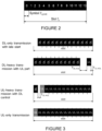
- An NR slot consists of several OFDM symbols, according to current agreements either 7 or 14 symbols (OFDM subcarrier spacing ⁇ 60 kHz) and 14 symbols (OFDM subcarrier spacing > 60 kHz).
- FIGURE 2 shows a subframe with 14 OFDM symbols.
- T s and T symb denote the slot and OFDM symbol duration, respectively.
- a slot may also be shortened to accommodate DL/LTL transient period or both DL and UL transmissions. Potential variations are shown in FIGURE 3 .
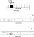
- NR also defines Type B scheduling, also known as mini-slots.
- Mini-slots are shorter than slots (according to current agreements from 1 or 2 symbols up to number of symbols in a slot minus one) and can start at any symbol.
- Mini-slots are used if the transmission duration of a slot is too long or the occurrence of the next slot start (slot alignment) is too late.
- Applications of mini-slots include among others latency critical transmissions (in this case both mini-slot length and frequent opportunity of mini-slot are important) and unlicensed spectrum where a transmission should start immediately after listen-before-talk succeeded (here the frequent opportunity of mini-slot is especially important).
- An example of mini-slots is shown in FIGURE 4 .
- a node For a node to be allowed to transmit in unlicensed spectrum, e.g. the 5GHz band, it typically needs to perform a clear channel assessment (CCA).
- CCA clear channel assessment
- This procedure typically includes sensing the medium to be idle for a number of time intervals. Sensing the medium to be idle can be done in different ways, e.g. using energy detection, preamble detection or using virtual carrier sensing. Where the latter implies that the node reads control information from other transmitting nodes informing when a transmission ends.
- TXOP transmission opportunity
- the length of the TXOP depends on regulation and type of CCA that has been performed, but typically ranges from 1ms to 10ms.
- the mini-slot concept in NR allows a node to access the channel at a much finer granularity compared to e.g. LTE LAA, where the channel could only be accessed at 500us intervals.
- LTE LAA Long Term Evolution
- the channel can be accessed at 36us intervals.
- LAA multi-subframe scheduling should be the baseline to enable scheduling multiple transmission time intervals (TTIs) for PUSCH using a single UL grant in NR.
- TTIs transmission time intervals
- the DCI should include, implicitly or explicitly, at least:
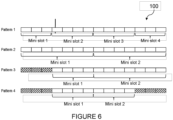
- the Time domain resource assignment field value m of the DCI provides a row index m + 1 to an allocated RRC configured table.
- FIGURE 5A illustrates one example configuration of an RRC configured table 50, wherein the indexed row defines:
- the Time domain resource assignment field value m of the DCI provides a row index m + 1 to an allocated RRC configured table.
- FIGURE 5B illustrates another example configuration of an RRC configured table 55, wherein the indexed row defines:
- the existing RRC configured table for PUSCH allocation List with (K2, S and L) is reused but with different interpretation:
- Multi-mini slot scheduling has two main advantages:
- the maximum number of mini-slots that can be scheduled using DCI for multi-mini-slot scheduling should be configured over RRC. Besides, multi-mini-slot scheduling should be limited to scheduling mini-slots within the maximum X slot(s).
- the DCI should include, implicitly or explicitly, at least:
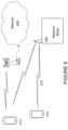
- one or multiple mini-slot patterns 100 are configured via RRC, see FIGURE 6 .
- the Pattern 100 indicates the start and end of every PUSCH.
- mini-slot periodicity is configured via RRC, which is equivalent to setting a mini-slot pattern with consecutive equal length PUSCH (e.g. mini slot periodicity is 7 symbols in Pattern 2 in FIGURE 6 ).
- DCI provides an index to the pattern to be used for UL transmission(s) within a slot.
- timeDomainAllocation indicated in DCI can be reused to indicate:
- the UE recalculate the length of the last mini-slot considering that the transmission would be terminated at symbol (S+L).
- DCI indicates implicitly or explicitly at which mini slot within the pattern the transmission should start and end.
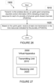
- one or multiple PUSCH starting positions 200 are configured via RRC, see FIGURE 7 .
- the PUSCH starting positions can be enabled/disabled dynamically in a multi-mini slot DCI. According to the enabled positions, the mini-slot(s) duration vary. A certain mini slot expands from a PUSCH starting position to the next enabled PUSCH starting position.
- FIGURE 8 shows an example of how the mini-slot pattern 300 may dynamically change depending on the enabled position via DCI.
- the DCI provides an indication corresponding to time resources, e.g. slot/mini-slot timing, which corresponds to a plurality of PUSCH transmissions.
- time resources e.g. slot/mini-slot timing
- the DCI provides uplink scheduling for the plurality of PUSCH in an efficient manner.
- the UE does not refer to the MCS value indicated by the DCI, but instead assumes the same TBS as in the initial transmission and rate match it to fit in the scheduled PUSCH.
- FIGURE 9 illustrates a wireless network, in accordance with some embodiments.
- a wireless network such as the example wireless network illustrated in FIGURE 9 .
- the wireless network of FIGURE 9 only depicts network 406, network nodes 460 and 460b, and wireless devices 410, 410b, and 410c.
- a wireless network may further include any additional elements suitable to support communication between wireless devices or between a wireless device and another communication device, such as a landline telephone, a service provider, or any other network node or end device.
- network node 460 and wireless device 410 are depicted with additional detail.
- the wireless network may provide communication and other types of services to one or more wireless devices to facilitate the wireless devices' access to and/or use of the services provided by, or via, the wireless network.
- the wireless network may comprise and/or interface with any type of communication, telecommunication, data, cellular, and/or radio network or other similar type of system.
- the wireless network may be configured to operate according to specific standards or other types of predefined rules or procedures.
- particular embodiments of the wireless network may implement communication standards, such as Global System for Mobile Communications (GSM), Universal Mobile Telecommunications System (UMTS), Long Term Evolution (LTE), and/or other suitable 2G, 3G, 4G, or 5G standards; wireless local area network (WLAN) standards, such as the IEEE 802.11 standards; and/or any other appropriate wireless communication standard, such as the Worldwide Interoperability for Microwave Access (WiMax), Bluetooth, Z-Wave and/or ZigBee standards.
- GSM Global System for Mobile Communications
- UMTS Universal Mobile Telecommunications System
- LTE Long Term Evolution
- WLAN wireless local area network
- WiMax Worldwide Interoperability for Microwave Access
- Bluetooth Z-Wave and/or ZigBee standards.
- Network 406 may comprise one or more backhaul networks, core networks, IP networks, public switched telephone networks (PSTNs), packet data networks, optical networks, wide-area networks (WANs), local area networks (LANs), wireless local area networks (WLANs), wired networks, wireless networks, metropolitan area networks, and other networks to enable communication between devices.
- PSTNs public switched telephone networks
- WANs wide-area networks
- LANs local area networks
- WLANs wireless local area networks
- wired networks wireless networks, metropolitan area networks, and other networks to enable communication between devices.
- Network node 460 and wireless device 410 comprise various components described in more detail below. These components work together in order to provide network node and/or wireless device functionality, such as providing wireless connections in a wireless network.
- the wireless network may comprise any number of wired or wireless networks, network nodes, base stations, controllers, wireless devices, relay stations, and/or any other components or systems that may facilitate or participate in the communication of data and/or signals whether via wired or wireless connections.
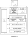
- FIGURE 10 illustrates an example network node 460, according to certain embodiments.
- network node refers to equipment capable, configured, arranged and/or operable to communicate directly or indirectly with a wireless device and/or with other network nodes or equipment in the wireless network to enable and/or provide wireless access to the wireless device and/or to perform other functions (e.g., administration) in the wireless network.
- network nodes include, but are not limited to, access points (APs) (e.g., radio access points), base stations (BSs) (e.g., radio base stations, Node Bs, evolved Node Bs (eNBs) and NR NodeBs (gNBs)).
- APs access points
- BSs base stations
- eNBs evolved Node Bs
- gNBs NR NodeBs
- Base stations may be categorized based on the amount of coverage they provide (or, stated differently, their transmit power level) and may then also be referred to as femto base stations, pico base stations, micro base stations, or macro base stations.
- a base station may be a relay node or a relay donor node controlling a relay.
- a network node may also include one or more (or all) parts of a distributed radio base station such as centralized digital units and/or remote radio units (RRUs), sometimes referred to as Remote Radio Heads (RRHs). Such remote radio units may or may not be integrated with an antenna as an antenna integrated radio.
- RRUs remote radio units
- RRHs Remote Radio Heads
- Such remote radio units may or may not be integrated with an antenna as an antenna integrated radio.
- Parts of a distributed radio base station may also be referred to as nodes in a distributed antenna system (DAS).
- DAS distributed antenna system
- network nodes include multi-standard radio (MSR) equipment such as MSR BSs, network controllers such as radio network controllers (RNCs) or base station controllers (BSCs), base transceiver stations (BTSs), transmission points, transmission nodes, multi-cell/multicast coordination entities (MCEs), core network nodes (e.g., MSCs, MMEs), O&M nodes, OSS nodes, SON nodes, positioning nodes (e.g., E-SMLCs), and/or MDTs.
- MSR multi-standard radio
- RNCs radio network controllers
- BSCs base station controllers
- BTSs base transceiver stations
- transmission points transmission nodes
- MCEs multi-cell/multicast coordination entities
- core network nodes e.g., MSCs, MMEs
- O&M nodes e.g., OSS nodes, SON nodes, positioning nodes (e.g., E-SMLCs), and/or MDTs.
- network nodes may represent any suitable device (or group of devices) capable, configured, arranged, and/or operable to enable and/or provide a wireless device with access to the wireless network or to provide some service to a wireless device that has accessed the wireless network.
- network node 460 includes processing circuitry 470, device readable medium 480, interface 490, auxiliary equipment 484, power source 486, power circuitry 487, and antenna 462.
- network node 460 illustrated in the example wireless network of FIGURE 10 may represent a device that includes the illustrated combination of hardware components, other embodiments may comprise network nodes with different combinations of components. It is to be understood that a network node comprises any suitable combination of hardware and/or software needed to perform the tasks, features, functions and methods disclosed herein.
- network node 460 may comprise multiple different physical components that make up a single illustrated component (e.g., device readable medium 480 may comprise multiple separate hard drives as well as multiple RAM modules).
- network node 460 may be composed of multiple physically separate components (e.g., a NodeB component and a RNC component, or a BTS component and a BSC component, etc.), which may each have their own respective components.
- network node 460 comprises multiple separate components (e.g., BTS and BSC components)
- one or more of the separate components may be shared among several network nodes.
- a single RNC may control multiple NodeB's.
- each unique NodeB and RNC pair may in some instances be considered a single separate network node.
- network node 460 may be configured to support multiple radio access technologies (RATs).
- RATs radio access technologies
- Network node 460 may also include multiple sets of the various illustrated components for different wireless technologies integrated into network node 460, such as, for example, GSM, WCDMA, LTE, NR, WiFi, or Bluetooth wireless technologies. These wireless technologies may be integrated into the same or different chip or set of chips and other components within network node 460.
- Processing circuitry 470 is configured to perform any determining, calculating, or similar operations (e.g., certain obtaining operations) described herein as being provided by a network node. These operations performed by processing circuitry 470 may include processing information obtained by processing circuitry 470 by, for example, converting the obtained information into other information, comparing the obtained information or converted information to information stored in the network node, and/or performing one or more operations based on the obtained information or converted information, and as a result of said processing making a determination.
- processing information obtained by processing circuitry 470 by, for example, converting the obtained information into other information, comparing the obtained information or converted information to information stored in the network node, and/or performing one or more operations based on the obtained information or converted information, and as a result of said processing making a determination.
- Processing circuitry 470 may comprise a combination of one or more of a microprocessor, controller, microcontroller, central processing unit, digital signal processor, application-specific integrated circuit, field programmable gate array, or any other suitable computing device, resource, or combination of hardware, software and/or encoded logic operable to provide, either alone or in conjunction with other network node 460 components, such as device readable medium 480, network node 460 functionality.
- processing circuitry 470 may execute instructions stored in device readable medium 480 or in memory within processing circuitry 470. Such functionality may include providing any of the various wireless features, functions, or benefits discussed herein.
- processing circuitry 470 may include a system on a chip (SOC).
- SOC system on a chip
- processing circuitry 470 may include one or more of radio frequency (RF) transceiver circuitry 472 and baseband processing circuitry 474.
- radio frequency (RF) transceiver circuitry 472 and baseband processing circuitry 474 may be on separate chips (or sets of chips), boards, or units, such as radio units and digital units.
- part or all of RF transceiver circuitry 472 and baseband processing circuitry 474 may be on the same chip or set of chips, boards, or units.
- processing circuitry 470 executing instructions stored on device readable medium 480 or memory within processing circuitry 470.
- some or all of the functionality may be provided by processing circuitry 470 without executing instructions stored on a separate or discrete device readable medium, such as in a hard-wired manner.
- processing circuitry 470 can be configured to perform the described functionality. The benefits provided by such functionality are not limited to processing circuitry 470 alone or to other components of network node 460 but are enjoyed by network node 460 as a whole, and/or by end users and the wireless network generally.
- Device readable medium 480 may comprise any form of volatile or non-volatile computer readable memory including, without limitation, persistent storage, solid-state memory, remotely mounted memory, magnetic media, optical media, random access memory (RAM), read-only memory (ROM), mass storage media (for example, a hard disk), removable storage media (for example, a flash drive, a Compact Disk (CD) or a Digital Video Disk (DVD)), and/or any other volatile or non-volatile, non-transitory device readable and/or computer-executable memory devices that store information, data, and/or instructions that may be used by processing circuitry 470.
- volatile or non-volatile computer readable memory including, without limitation, persistent storage, solid-state memory, remotely mounted memory, magnetic media, optical media, random access memory (RAM), read-only memory (ROM), mass storage media (for example, a hard disk), removable storage media (for example, a flash drive, a Compact Disk (CD) or a Digital Video Disk (DVD)), and/or any other volatile or
- Device readable medium 480 may store any suitable instructions, data or information, including a computer program, software, an application including one or more of logic, rules, code, tables, etc. and/or other instructions capable of being executed by processing circuitry 470 and, utilized by network node 460.
- Device readable medium 480 may be used to store any calculations made by processing circuitry 470 and/or any data received via interface 490.
- processing circuitry 470 and device readable medium 480 may be considered to be integrated.
- Interface 490 is used in the wired or wireless communication of signaling and/or data between network node 460, network 406, and/or wireless devices 410. As illustrated, interface 490 comprises port(s)/terminal(s) 494 to send and receive data, for example to and from network 406 over a wired connection. Interface 490 also includes radio front end circuitry 492 that may be coupled to, or in certain embodiments a part of, antenna 462. Radio front end circuitry 492 comprises filters 498 and amplifiers 496. Radio front end circuitry 492 may be connected to antenna 462 and processing circuitry 470. Radio front end circuitry may be configured to condition signals communicated between antenna 462 and processing circuitry 470.
- Radio front end circuitry 492 may receive digital data that is to be sent out to other network nodes or wireless devices via a wireless connection. Radio front end circuitry 492 may convert the digital data into a radio signal having the appropriate channel and bandwidth parameters using a combination of filters 498 and/or amplifiers 496. The radio signal may then be transmitted via antenna 462. Similarly, when receiving data, antenna 462 may collect radio signals which are then converted into digital data by radio front end circuitry 492. The digital data may be passed to processing circuitry 470. In other embodiments, the interface may comprise different components and/or different combinations of components.
- network node 460 may not include separate radio front end circuitry 492, instead, processing circuitry 470 may comprise radio front end circuitry and may be connected to antenna 462 without separate radio front end circuitry 492. Similarly, in some embodiments, all or some of RF transceiver circuitry 472 may be considered a part of interface 490. In still other embodiments, interface 490 may include one or more ports or terminals 494, radio front end circuitry 492, and RF transceiver circuitry 472, as part of a radio unit (not shown), and interface 490 may communicate with baseband processing circuitry 474, which is part of a digital unit (not shown).
- Antenna 462 may include one or more antennas, or antenna arrays, configured to send and/or receive wireless signals. Antenna 462 may be coupled to radio front end circuitry 490 and may be any type of antenna capable of transmitting and receiving data and/or signals wirelessly.
- antenna 462 may comprise one or more omni-directional, sector or panel antennas operable to transmit/receive radio signals between, for example, 2 GHz and 66 GHz.
- An omni-directional antenna may be used to transmit/receive radio signals in any direction
- a sector antenna may be used to transmit/receive radio signals from devices within a particular area
- a panel antenna may be a line of sight antenna used to transmit/receive radio signals in a relatively straight line.
- the use of more than one antenna may be referred to as MIMO.
- antenna 462 may be separate from network node 460 and may be connectable to network node 460 through an interface or port.
- Antenna 462, interface 490, and/or processing circuitry 470 may be configured to perform any receiving operations and/or certain obtaining operations described herein as being performed by a network node. Any information, data and/or signals may be received from a wireless device, another network node and/or any other network equipment. Similarly, antenna 462, interface 490, and/or processing circuitry 470 may be configured to perform any transmitting operations described herein as being performed by a network node. Any information, data and/or signals may be transmitted to a wireless device, another network node and/or any other network equipment.
- Power circuitry 487 may comprise, or be coupled to, power management circuitry and is configured to supply the components of network node 460 with power for performing the functionality described herein. Power circuitry 487 may receive power from power source 486. Power source 486 and/or power circuitry 487 may be configured to provide power to the various components of network node 460 in a form suitable for the respective components (e.g., at a voltage and current level needed for each respective component). Power source 486 may either be included in, or external to, power circuitry 487 and/or network node 460.
- network node 460 may be connectable to an external power source (e.g., an electricity outlet) via an input circuitry or interface such as an electrical cable, whereby the external power source supplies power to power circuitry 487.
- power source 486 may comprise a source of power in the form of a battery or battery pack which is connected to, or integrated in, power circuitry 487. The battery may provide backup power should the external power source fail.
- Other types of power sources such as photovoltaic devices, may also be used.
- network node 460 may include additional components beyond those shown in FIGURE 10 that may be responsible for providing certain aspects of the network node's functionality, including any of the functionality described herein and/or any functionality necessary to support the subject matter described herein.
- network node 460 may include user interface equipment to allow input of information into network node 460 and to allow output of information from network node 460. This may allow a user to perform diagnostic, maintenance, repair, and other administrative functions for network node 460.
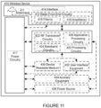
- FIGURE 11 illustrates an example wireless device, according to certain embodiments.
- wireless device refer to a device capable, configured, arranged and/or operable to communicate wirelessly with network nodes and/or other wireless devices.
- the term wireless device may be used interchangeably herein with user equipment (UE).
- Communicating wirelessly may involve transmitting and/or receiving wireless signals using electromagnetic waves, radio waves, infrared waves, and/or other types of signals suitable for conveying information through air.
- a wireless device may be configured to transmit and/or receive information without direct human interaction.
- a wireless device may be designed to transmit information to a network on a predetermined schedule, when triggered by an internal or external event, or in response to requests from the network.
- Examples of a wireless device include, but are not limited to, a smart phone, a mobile phone, a cell phone, a voice over IP (VoIP) phone, a wireless local loop phone, a desktop computer, a personal digital assistant (PDA), a wireless cameras, a gaming console or device, a music storage device, a playback appliance, a wearable terminal device, a wireless endpoint, a mobile station, a tablet, a laptop, a laptop-embedded equipment (LEE), a laptop-mounted equipment (LME), a smart device, a wireless customer-premise equipment (CPE). a vehicle-mounted wireless terminal device, etc.
- VoIP voice over IP
- PDA personal digital assistant
- PDA personal digital assistant
- a wireless cameras a gaming console or device
- a music storage device a playback appliance
- a wearable terminal device a wireless endpoint
- a mobile station a tablet, a laptop, a laptop-embedded equipment (LEE), a laptop-mounted equipment (L
- a wireless device may support device-to-device (D2D) communication, for example by implementing a 3GPP standard for sidelink communication, vehicle-to-vehicle (V2V), vehicle-to-infrastructure (V2I), vehicle-to-everything (V2X) and may in this case be referred to as a D2D communication device.
- D2D device-to-device
- V2V vehicle-to-vehicle
- V2I vehicle-to-infrastructure
- V2X vehicle-to-everything
- a wireless device may represent a machine or other device that performs monitoring and/or measurements and transmits the results of such monitoring and/or measurements to another wireless device and/or a network node.
- the wireless device may in this case be a machine-to-machine (M2M) device, which may in a 3GPP context be referred to as an MTC device.
- M2M machine-to-machine
- the wireless device may be a UE implementing the 3GPP narrow band internet of things (NB-IoT) standard.
- NB-IoT narrow band internet of things
- machines or devices are sensors, metering devices such as power meters, industrial machinery, or home or personal appliances (e.g. refrigerators, televisions, etc.) personal wearables (e.g., watches, fitness trackers, etc.).
- a wireless device may represent a vehicle or other equipment that is capable of monitoring and/or reporting on its operational status or other functions associated with its operation.
- a wireless device as described above may represent the endpoint of a wireless connection, in which case the device may be referred to as a wireless terminal. Furthermore, a wireless device as described above may be mobile, in which case it may also be referred to as a mobile device or a mobile terminal.
- wireless device 410 includes antenna 411, interface 414, processing circuitry 420, device readable medium 430, user interface equipment 432, auxiliary equipment 434, power source 436 and power circuitry 437.
- wireless device 410 may include multiple sets of one or more of the illustrated components for different wireless technologies supported by wireless device 410, such as, for example, GSM, WCDMA, LTE, NR, WiFi, WiMAX, or Bluetooth wireless technologies, just to mention a few. These wireless technologies may be integrated into the same or different chips or set of chips as other components within wireless device 410.
- Antenna 411 may include one or more antennas or antenna arrays, configured to send and/or receive wireless signals, and is connected to interface 414. In certain alternative embodiments, antenna 411 may be separate from wireless device 410 and be connectable to wireless device 410 through an interface or port. Antenna 411, interface 414, and/or processing circuitry 420 may be configured to perform any receiving or transmitting operations described herein as being performed by a wireless device. Any information, data and/or signals may be received from a network node and/or another wireless device. In some embodiments, radio front end circuitry and/or antenna 411 may be considered an interface.
- interface 414 comprises radio front end circuitry 412 and antenna 411.
- Radio front end circuitry 412 comprise one or more filters 418 and amplifiers 416.
- Radio front end circuitry 414 is connected to antenna 411 and processing circuitry 420 and is configured to condition signals communicated between antenna 411 and processing circuitry 420.
- Radio front end circuitry 412 may be coupled to or a part of antenna 411.
- wireless device 410 may not include separate radio front end circuitry 412; rather, processing circuitry 420 may comprise radio front end circuitry and may be connected to antenna 411.
- some or all of RF transceiver circuitry 422 may be considered a part of interface 414.
- Radio front end circuitry 412 may receive digital data that is to be sent out to other network nodes or wireless devices via a wireless connection. Radio front end circuitry 412 may convert the digital data into a radio signal having the appropriate channel and bandwidth parameters using a combination of filters 418 and/or amplifiers 416. The radio signal may then be transmitted via antenna 411. Similarly, when receiving data, antenna 411 may collect radio signals which are then converted into digital data by radio front end circuitry 412. The digital data may be passed to processing circuitry 420. In other embodiments, the interface may comprise different components and/or different combinations of components.
- Processing circuitry 420 may comprise a combination of one or more of a microprocessor, controller, microcontroller, central processing unit, digital signal processor, application-specific integrated circuit, field programmable gate array, or any other suitable computing device, resource, or combination of hardware, software, and/or encoded logic operable to provide, either alone or in conjunction with other wireless device 410 components, such as device readable medium 430, wireless device 410 functionality. Such functionality may include providing any of the various wireless features or benefits discussed herein. For example, processing circuitry 420 may execute instructions stored in device readable medium 430 or in memory within processing circuitry 420 to provide the functionality disclosed herein.
- processing circuitry 420 includes one or more of RF transceiver circuitry 422, baseband processing circuitry 424, and application processing circuitry 426.
- the processing circuitry may comprise different components and/or different combinations of components.
- processing circuitry 420 of wireless device 410 may comprise a SOC.
- RF transceiver circuitry 422, baseband processing circuitry 424, and application processing circuitry 426 may be on separate chips or sets of chips.
- part or all of baseband processing circuitry 424 and application processing circuitry 426 may be combined into one chip or set of chips, and RF transceiver circuitry 422 may be on a separate chip or set of chips.
- part or all of RF transceiver circuitry 422 and baseband processing circuitry 424 may be on the same chip or set of chips, and application processing circuitry 426 may be on a separate chip or set of chips.
- part or all of RF transceiver circuitry 422, baseband processing circuitry 424, and application processing circuitry 426 may be combined in the same chip or set of chips.
- RF transceiver circuitry 422 may be a part of interface 414.
- RF transceiver circuitry 422 may condition RF signals for processing circuitry 420.
- processing circuitry 420 executing instructions stored on device readable medium 430, which in certain embodiments may be a computer-readable storage medium.
- some or all of the functionality may be provided by processing circuitry 420 without executing instructions stored on a separate or discrete device readable storage medium, such as in a hard-wired manner.
- processing circuitry 420 can be configured to perform the described functionality. The benefits provided by such functionality are not limited to processing circuitry 420 alone or to other components of wireless device 410, but are enjoyed by wireless device 410 as a whole, and/or by end users and the wireless network generally.
- Processing circuitry 420 may be configured to perform any determining, calculating, or similar operations (e.g., certain obtaining operations) described herein as being performed by a wireless device. These operations, as performed by processing circuitry 420, may include processing information obtained by processing circuitry 420 by, for example, converting the obtained information into other information, comparing the obtained information or converted information to information stored by wireless device 410, and/or performing one or more operations based on the obtained information or converted information, and as a result of said processing making a determination.
- processing information obtained by processing circuitry 420 by, for example, converting the obtained information into other information, comparing the obtained information or converted information to information stored by wireless device 410, and/or performing one or more operations based on the obtained information or converted information, and as a result of said processing making a determination.
- Device readable medium 430 may be operable to store a computer program, software, an application including one or more of logic, rules, code, tables, etc. and/or other instructions capable of being executed by processing circuitry 420.
- Device readable medium 430 may include computer memory (e.g., Random Access Memory (RAM) or Read Only Memory (ROM)), mass storage media (e.g., a hard disk), removable storage media (e.g., a Compact Disk (CD) or a Digital Video Disk (DVD)), and/or any other volatile or non-volatile, non-transitory device readable and/or computer executable memory devices that store information, data, and/or instructions that may be used by processing circuitry 420.
- processing circuitry 420 and device readable medium 430 may be considered to be integrated.
- User interface equipment 432 may provide components that allow for a human user to interact with wireless device 410. Such interaction may be of many forms, such as visual, audial, tactile, etc. User interface equipment 432 may be operable to produce output to the user and to allow the user to provide input to wireless device 410. The type of interaction may vary depending on the type of user interface equipment 432 installed in wireless device 410. For example, if wireless device 410 is a smart phone, the interaction may be via a touch screen; if wireless device 410 is a smart meter, the interaction may be through a screen that provides usage (e.g., the number of gallons used) or a speaker that provides an audible alert (e.g., if smoke is detected).
- usage e.g., the number of gallons used
- a speaker that provides an audible alert
- User interface equipment 432 may include input interfaces, devices and circuits, and output interfaces, devices and circuits. User interface equipment 432 is configured to allow input of information into wireless device 410 and is connected to processing circuitry 420 to allow processing circuitry 420 to process the input information. User interface equipment 432 may include, for example, a microphone, a proximity or other sensor, keys/buttons, a touch display, one or more cameras, a USB port, or other input circuitry. User interface equipment 432 is also configured to allow output of information from wireless device 410, and to allow processing circuitry 420 to output information from wireless device 410. User interface equipment 432 may include, for example, a speaker, a display, vibrating circuitry, a USB port, a headphone interface, or other output circuitry. Using one or more input and output interfaces, devices, and circuits, of user interface equipment 432, wireless device 410 may communicate with end users and/or the wireless network and allow them to benefit from the functionality described herein.
- Auxiliary equipment 434 is operable to provide more specific functionality which may not be generally performed by wireless devices. This may comprise specialized sensors for doing measurements for various purposes, interfaces for additional types of communication such as wired communications etc. The inclusion and type of components of auxiliary equipment 434 may vary depending on the embodiment and/or scenario.
- Power source 436 may, in some embodiments, be in the form of a battery or battery pack. Other types of power sources, such as an external power source (e.g., an electricity outlet), photovoltaic devices or power cells, may also be used.
- wireless device 410 may further comprise power circuitry 437 for delivering power from power source 436 to the various parts of wireless device 410 which need power from power source 436 to carry out any functionality described or indicated herein.
- Power circuitry 437 may in certain embodiments comprise power management circuitry.
- Power circuitry 437 may additionally or alternatively be operable to receive power from an external power source; in which case wireless device 410 may be connectable to the external power source (such as an electricity outlet) via input circuitry or an interface such as an electrical power cable.
- Power circuitry 437 may also in certain embodiments be operable to deliver power from an external power source to power source 436. This may be, for example, for the charging of power source 436. Power circuitry 437 may perform any formatting, converting, or other modification to the power from power source 436 to make the power suitable for the respective components of wireless device 410 to which power is supplied.
- FIGURE 12 illustrates one embodiment of a UE 500 in accordance with various aspects described herein.
- a user equipment or UE may not necessarily have a user in the sense of a human user who owns and/or operates the relevant device.
- a UE may represent a device that is intended for sale to, or operation by, a human user but which may not, or which may not initially, be associated with a specific human user (e.g., a smart sprinkler controller).
- a UE may represent a device that is not intended for sale to, or operation by, an end user but which may be associated with or operated for the benefit of a user (e.g., a smart power meter).
- UE 500 may be any UE identified by the 3 rd Generation Partnership Project (3GPP), including a NB-IoT UE, a machine type communication (MTC) UE, and/or an enhanced MTC (eMTC) UE.
- UE 500 as illustrated in FIGURE 12 , is one example of a wireless device configured for communication in accordance with one or more communication standards promulgated by the 3 rd Generation Partnership Project (3GPP), such as 3GPP's GSM, UMTS, LTE, and/or 5G standards.
- 3GPP 3 rd Generation Partnership Project
- GSM Global System for Mobile communications
- UMTS Universal Mobile communications
- LTE Long Term Evolution
- 5G 5G
- the term wireless device and UE may be used interchangeable. Accordingly, although FIGURE 12 is a UE, the components discussed herein are equally applicable to a wireless device, and vice-versa.
- UE 500 includes processing circuitry 501 that is operatively coupled to input/output interface 505, radio frequency (RF) interface 509, network connection interface 511, memory 515 including random access memory (RAM) 517, read-only memory (ROM) 519, and storage medium 521 or the like, communication subsystem 531, power source 533, and/or any other component, or any combination thereof.
- Storage medium 521 includes operating system 523, application program 525, and data 527. In other embodiments, storage medium 521 may include other similar types of information.
- Certain UEs may utilize all of the components shown in FIGURE 12 , or only a subset of the components. The level of integration between the components may vary from one UE to another UE. Further, certain UEs may contain multiple instances of a component, such as multiple processors, memories, transceivers, transmitters, receivers, etc.
- processing circuitry 501 may be configured to process computer instructions and data.
- Processing circuitry 501 may be configured to implement any sequential state machine operative to execute machine instructions stored as machine-readable computer programs in the memory, such as one or more hardware-implemented state machines (e.g., in discrete logic, FPGA, ASIC, etc.); programmable logic together with appropriate firmware; one or more stored program, general-purpose processors, such as a microprocessor or Digital Signal Processor (DSP), together with appropriate software; or any combination of the above.
- the processing circuitry 501 may include two central processing units (CPUs). Data may be information in a form suitable for use by a computer.
- input/output interface 505 may be configured to provide a communication interface to an input device, output device, or input and output device.
- UE 500 may be configured to use an output device via input/output interface 505.
- An output device may use the same type of interface port as an input device.
- a USB port may be used to provide input to and output from UE 500.
- the output device may be a speaker, a sound card, a video card, a display, a monitor, a printer, an actuator, an emitter, a smartcard, another output device, or any combination thereof.
- UE 500 may be configured to use an input device via input/output interface 505 to allow a user to capture information into UE 500.
- the input device may include a touch-sensitive or presence-sensitive display, a camera (e.g., a digital camera, a digital video camera, a web camera, etc.), a microphone, a sensor, a mouse, a trackball, a directional pad, a trackpad, a scroll wheel, a smartcard, and the like.
- the presence-sensitive display may include a capacitive or resistive touch sensor to sense input from a user.
- a sensor may be, for instance, an accelerometer, a gyroscope, a tilt sensor, a force sensor, a magnetometer, an optical sensor, a proximity sensor, another like sensor, or any combination thereof.
- the input device may be an accelerometer, a magnetometer, a digital camera, a microphone, and an optical sensor.
- RF interface 509 may be configured to provide a communication interface to RF components such as a transmitter, a receiver, and an antenna.
- Network connection interface 511 may be configured to provide a communication interface to network 543a.
- Network 543a may encompass wired and/or wireless networks such as a local-area network (LAN), a wide-area network (WAN), a computer network, a wireless network, a telecommunications network, another like network or any combination thereof.
- network 543a may comprise a Wi-Fi network.
- Network connection interface 511 may be configured to include a receiver and a transmitter interface used to communicate with one or more other devices over a communication network according to one or more communication protocols, such as Ethernet, TCP/IP, SONET, ATM, or the like.
- Network connection interface 511 may implement receiver and transmitter functionality appropriate to the communication network links (e.g., optical, electrical, and the like). The transmitter and receiver functions may share circuit components, software or firmware, or alternatively may be implemented separately.
- RAM 517 may be configured to interface via bus 502 to processing circuitry 501 to provide storage or caching of data or computer instructions during the execution of software programs such as the operating system, application programs, and device drivers.
- ROM 519 may be configured to provide computer instructions or data to processing circuitry 501.
- ROM 519 may be configured to store invariant low-level system code or data for basic system functions such as basic input and output (I/O), startup, or reception of keystrokes from a keyboard that are stored in a non-volatile memory.
- Storage medium 521 may be configured to include memory such as RAM, ROM, programmable read-only memory (PROM), erasable programmable read-only memory (EPROM), electrically erasable programmable read-only memory (EEPROM), magnetic disks, optical disks, floppy disks, hard disks, removable cartridges, or flash drives.
- storage medium 521 may be configured to include operating system 523, application program 525 such as a web browser application, a widget or gadget engine or another application, and data file 527.
- Storage medium 521 may store, for use by UE 500, any of a variety of various operating systems or combinations of operating systems.
- Storage medium 521 may be configured to include a number of physical drive units, such as redundant array of independent disks (RAID), floppy disk drive, flash memory, USB flash drive, external hard disk drive, thumb drive, pen drive, key drive, high-density digital versatile disc (HD-DVD) optical disc drive, internal hard disk drive, Blu-Ray optical disc drive, holographic digital data storage (HDDS) optical disc drive, external mini-dual in-line memory module (DIMM), synchronous dynamic random access memory (SDRAM), external micro-DIMM SDRAM, smartcard memory such as a subscriber identity module or a removable user identity (SIM/RUIM) module, other memory, or any combination thereof.
- RAID redundant array of independent disks
- HD-DVD high-density digital versatile disc
- HDDS holographic digital data storage
- DIMM external mini-dual in-line memory module
- SDRAM synchronous dynamic random access memory
- SDRAM synchronous dynamic random access memory
- smartcard memory such as a subscriber identity module or a removable user
- Storage medium 521 may allow UE 500 to access computer-executable instructions, application programs or the like, stored on transitory or non-transitory memory media, to off-load data, or to upload data.
- An article of manufacture, such as one utilizing a communication system may be tangibly embodied in storage medium 521, which may comprise a device readable medium.
- processing circuitry 501 may be configured to communicate with network 543b using communication subsystem 531.
- Network 543a and network 543b may be the same network or networks or different network or networks.
- Communication subsystem 531 may be configured to include one or more transceivers used to communicate with network 543b.
- communication subsystem 531 may be configured to include one or more transceivers used to communicate with one or more remote transceivers of another device capable of wireless communication such as another wireless device, UE, or base station of a radio access network (RAN) according to one or more communication protocols, such as IEEE 802.5, CDMA, WCDMA, GSM, LTE, UTRAN, WiMax, or the like.
- RAN radio access network
- Each transceiver may include transmitter 533 and/or receiver 535 to implement transmitter or receiver functionality, respectively, appropriate to the RAN links (e.g., frequency allocations and the like). Further, transmitter 533 and receiver 535 of each transceiver may share circuit components, software or firmware, or alternatively may be implemented separately.
- the communication functions of communication subsystem 531 may include data communication, voice communication, multimedia communication, short-range communications such as Bluetooth, near-field communication, location-based communication such as the use of the global positioning system (GPS) to determine a location, another like communication function, or any combination thereof.
- communication subsystem 531 may include cellular communication, Wi-Fi communication, Bluetooth communication, and GPS communication.
- Network 543b may encompass wired and/or wireless networks such as a local-area network (LAN), a wide-area network (WAN), a computer network, a wireless network, a telecommunications network, another like network or any combination thereof.
- network 543b may be a cellular network, a Wi-Fi network, and/or a near-field network.
- Power source 513 may be configured to provide alternating current (AC) or direct current (DC) power to components of UE 500.
- communication subsystem 531 may be configured to include any of the components described herein.
- processing circuitry 501 may be configured to communicate with any of such components over bus 502.
- any of such components may be represented by program instructions stored in memory that when executed by processing circuitry 501 perform the corresponding functions described herein.
- the functionality of any of such components may be partitioned between processing circuitry 501 and communication subsystem 531.
- the non-computationally intensive functions of any of such components may be implemented in software or firmware and the computationally intensive functions may be implemented in hardware.
- FIGURE 13 is a schematic block diagram illustrating a virtualization environment 600 in which functions implemented by some embodiments may be virtualized.
- virtualizing means creating virtual versions of apparatuses or devices which may include virtualizing hardware platforms, storage devices and networking resources.
- virtualization can be applied to a node (e.g., a virtualized base station or a virtualized radio access node) or to a device (e.g., a UE, a wireless device or any other type of communication device) or components thereof and relates to an implementation in which at least a portion of the functionality is implemented as one or more virtual components (e.g., via one or more applications, components, functions, virtual machines or containers executing on one or more physical processing nodes in one or more networks).
- a node e.g., a virtualized base station or a virtualized radio access node
- a device e.g., a UE, a wireless device or any other type of communication device
- some or all of the functions described herein may be implemented as virtual components executed by one or more virtual machines implemented in one or more virtual environments 600 hosted by one or more of hardware nodes 630. Further, in embodiments in which the virtual node is not a radio access node or does not require radio connectivity (e.g., a core network node), then the network node may be entirely virtualized.
- the functions may be implemented by one or more applications 620 (which may alternatively be called software instances, virtual appliances, network functions, virtual nodes, virtual network functions, etc.) operative to implement some of the features, functions, and/or benefits of some of the embodiments disclosed herein.
- Applications 620 are run in virtualization environment 600 which provides hardware 630 comprising processing circuitry 660 and memory 690.
- Memory 690 contains instructions 695 executable by processing circuitry 660 whereby application 620 is operative to provide one or more of the features, benefits, and/or functions disclosed herein.
- Virtualization environment 600 comprises general-purpose or special-purpose network hardware devices 630 comprising a set of one or more processors or processing circuitry 660, which may be commercial off-the-shelf (COTS) processors, dedicated Application Specific Integrated Circuits (ASICs), or any other type of processing circuitry including digital or analog hardware components or special purpose processors.
- processors or processing circuitry 660 may be commercial off-the-shelf (COTS) processors, dedicated Application Specific Integrated Circuits (ASICs), or any other type of processing circuitry including digital or analog hardware components or special purpose processors.
- Each hardware device may comprise memory 690-1 which may be non-persistent memory for temporarily storing instructions 695 or software executed by processing circuitry 660.
- Each hardware device may comprise one or more network interface controllers (NICs) 670, also known as network interface cards, which include physical network interface 680.
- NICs network interface controllers
- Each hardware device may also include non-transitory, persistent, machine-readable storage media 690-2 having stored therein software 695 and/or instructions executable by processing circuitry 660.
- Software 695 may include any type of software including software for instantiating one or more virtualization layers 650 (also referred to as hypervisors), software to execute virtual machines 640 as well as software allowing it to execute functions, features and/or benefits described in relation with some embodiments described herein.
- Virtual machines 640 comprise virtual processing, virtual memory, virtual networking or interface and virtual storage, and may be run by a corresponding virtualization layer 650 or hypervisor. Different embodiments of the instance of virtual appliance 620 may be implemented on one or more of virtual machines 640, and the implementations may be made in different ways.
- processing circuitry 660 executes software 695 to instantiate the hypervisor or virtualization layer 650, which may sometimes be referred to as a virtual machine monitor (VMM).
- Virtualization layer 650 may present a virtual operating platform that appears like networking hardware to virtual machine 640.
- hardware 630 may be a standalone network node with generic or specific components. Hardware 630 may comprise antenna 6225 and may implement some functions via virtualization. Alternatively, hardware 630 may be part of a larger cluster of hardware (e.g. such as in a data center or customer premise equipment (CPE)) where many hardware nodes work together and are managed via management and orchestration (MANO) 6100, which, among others, oversees lifecycle management of applications 620.
- CPE customer premise equipment
- MANO management and orchestration
- NFV network function virtualization
- NFV may be used to consolidate many network equipment types onto industry standard high volume server hardware, physical switches, and physical storage, which can be located in data centers, and customer premise equipment.
- virtual machine 640 may be a software implementation of a physical machine that runs programs as if they were executing on a physical, non-virtualized machine.
- Each of virtual machines 640, and that part of hardware 630 that executes that virtual machine be it hardware dedicated to that virtual machine and/or hardware shared by that virtual machine with others of the virtual machines 640, forms a separate virtual network elements (VNE).
- VNE virtual network elements
- VNF Virtual Network Function
- one or more radio units 6200 that each include one or more transmitters 6220 and one or more receivers 6210 may be coupled to one or more antennas 6225.
- Radio units 6200 may communicate directly with hardware nodes 630 via one or more appropriate network interfaces and may be used in combination with the virtual components to provide a virtual node with radio capabilities, such as a radio access node or a base station.
- control system 6230 which may alternatively be used for communication between the hardware nodes 630 and radio units 6200.
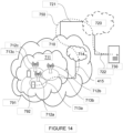
- FIGURE 14 illustrates a telecommunication network connected via an intermediate network to a host computer in accordance with some embodiments.
- a communication system includes telecommunication network 710, such as a 3GPP-type cellular network, which comprises access network 711, such as a radio access network, and core network 714.
- Access network 711 comprises a plurality of base stations 712a, 712b, 712c, such as NBs, eNBs, gNBs or other types of wireless access points, each defining a corresponding coverage area 713a, 713b, 713c.
- Each base station 712a, 712b, 712c is connectable to core network 714 over a wired or wireless connection 715.
- a first UE 791 located in coverage area 713c is configured to wirelessly connect to, or be paged by, the corresponding base station 712c.
- a second UE 792 in coverage area 713a is wirelessly connectable to the corresponding base station 712a. While a plurality of UEs 791, 792 are illustrated in this example, the disclosed embodiments are equally applicable to a situation where a sole UE is in the coverage area or where a sole UE is connecting to the corresponding base station 712.
- Telecommunication network 710 is itself connected to host computer 730, which may be embodied in the hardware and/or software of a standalone server, a cloud-implemented server, a distributed server or as processing resources in a server farm.
- Host computer 730 may be under the ownership or control of a service provider or may be operated by the service provider or on behalf of the service provider.
- Connections 721 and 722 between telecommunication network 710 and host computer 730 may extend directly from core network 714 to host computer 730 or may go via an optional intermediate network 720.
- Intermediate network 720 may be one of, or a combination of more than one of, a public, private or hosted network; intermediate network 720, if any, may be a backbone network or the Internet; in particular, intermediate network 720 may comprise two or more sub-networks (not shown).
- the communication system of FIGURE 14 as a whole enables connectivity between the connected UEs 791, 792 and host computer 730.
- the connectivity may be described as an over-the-top (OTT) connection 750.
- Host computer 730 and the connected UEs 791, 792 are configured to communicate data and/or signaling via OTT connection 750, using access network 711, core network 714, any intermediate network 720 and possible further infrastructure (not shown) as intermediaries.
- OTT connection 750 may be transparent in the sense that the participating communication devices through which OTT connection 750 passes are unaware of routing of uplink and downlink communications.
- base station 712 may not or need not be informed about the past routing of an incoming downlink communication with data originating from host computer 730 to be forwarded (e.g., handed over) to a connected UE 791. Similarly, base station 712 need not be aware of the future routing of an outgoing uplink communication originating from the UE 791 towards the host computer 730.
- FIGURE 15 illustrates a host computer communicating via a base station with a user equipment over a partially wireless connection in accordance with some embodiments.
- host computer 810 comprises hardware 815 including communication interface 816 configured to set up and maintain a wired or wireless connection with an interface of a different communication device of communication system 800.
- Host computer 810 further comprises processing circuitry 818, which may have storage and/or processing capabilities.
- processing circuitry 818 may comprise one or more programmable processors, application-specific integrated circuits, field programmable gate arrays or combinations of these (not shown) adapted to execute instructions.
- Host computer 810 further comprises software 811, which is stored in or accessible by host computer 810 and executable by processing circuitry 818.
- Software 811 includes host application 812.
- Host application 812 may be operable to provide a service to a remote user, such as UE 830 connecting via OTT connection 850 terminating at UE 830 and host computer 810. In providing the service to the remote user, host application 812 may provide user data which is transmitted using OTT connection 850.
- Communication system 800 further includes base station 820 provided in a telecommunication system and comprising hardware 825 enabling it to communicate with host computer 810 and with UE 830.
- Hardware 825 may include communication interface 826 for setting up and maintaining a wired or wireless connection with an interface of a different communication device of communication system 800, as well as radio interface 827 for setting up and maintaining at least wireless connection 870 with UE 830 located in a coverage area (not shown in Figure 8 ) served by base station 820.
- Communication interface 826 may be configured to facilitate connection 860 to host computer 810. Connection 860 may be direct or it may pass through a core network (not shown in Figure 8 ) of the telecommunication system and/or through one or more intermediate networks outside the telecommunication system.
- hardware 825 of base station 820 further includes processing circuitry 828, which may comprise one or more programmable processors, application-specific integrated circuits, field programmable gate arrays or combinations of these (not shown) adapted to execute instructions.
- processing circuitry 828 may comprise one or more programmable processors, application-specific integrated circuits, field programmable gate arrays or combinations of these (not shown) adapted to execute instructions.
- Base station 820 further has software 821 stored internally or accessible via an external connection.
- Communication system 800 further includes UE 830 already referred to. Its hardware 835 may include radio interface 837 configured to set up and maintain wireless connection 870 with a base station serving a coverage area in which UE 830 is currently located. Hardware 835 of UE 830 further includes processing circuitry 838, which may comprise one or more programmable processors, application-specific integrated circuits, field programmable gate arrays or combinations of these (not shown) adapted to execute instructions.
- UE 830 further comprises software 831, which is stored in or accessible by UE 830 and executable by processing circuitry 838.
- Software 831 includes client application 832. Client application 832 may be operable to provide a service to a human or non-human user via UE 830, with the support of host computer 810.
- an executing host application 812 may communicate with the executing client application 832 via OTT connection 850 terminating at UE 830 and host computer 810.
- client application 832 may receive request data from host application 812 and provide user data in response to the request data.
- OTT connection 850 may transfer both the request data and the user data.
- Client application 832 may interact with the user to generate the user data that it provides.
- host computer 810, base station 820 and UE 830 illustrated in FIGURE 15 may be similar or identical to host computer 730, one of base stations 712a, 712b, 712c and one of UEs 791, 792 of FIGURE 14 , respectively.
- the inner workings of these entities may be as shown in FIGURE 15 and independently, the surrounding network topology may be that of FIGURE 14 .
- OTT connection 850 has been drawn abstractly to illustrate the communication between host computer 810 and UE 830 via base station 820, without explicit reference to any intermediary devices and the precise routing of messages via these devices.
- Network infrastructure may determine the routing, which it may be configured to hide from UE 830 or from the service provider operating host computer 810, or both. While OTT connection 850 is active, the network infrastructure may further take decisions by which it dynamically changes the routing (e.g., on the basis of load balancing consideration or reconfiguration of the network).
- Wireless connection 870 between UE 830 and base station 820 is in accordance with the teachings of the embodiments described throughout this disclosure.
- One or more of the various embodiments improve the performance of OTT services provided to UE 830 using OTT connection 850, in which wireless connection 870 forms the last segment. More precisely, the teachings of these embodiments may improve the data rate, latency, and/or power consumption and thereby provide benefits such as reduced user waiting time, relaxed restriction on file size, better responsiveness, and/or extended battery lifetime.
- a measurement procedure may be provided for the purpose of monitoring data rate, latency and other factors on which the one or more embodiments improve.
- the measurement procedure and/or the network functionality for reconfiguring OTT connection 850 may be implemented in software 811 and hardware 815 of host computer 810 or in software 831 and hardware 835 of UE 830, or both.
- sensors (not shown) may be deployed in or in association with communication devices through which OTT connection 850 passes; the sensors may participate in the measurement procedure by supplying values of the monitored quantities exemplified above or supplying values of other physical quantities from which software 811, 831 may compute or estimate the monitored quantities.
- the reconfiguring of OTT connection 850 may include message format, retransmission settings, preferred routing etc.; the reconfiguring need not affect base station 820, and it may be unknown or imperceptible to base station 820. Such procedures and functionalities may be known and practiced in the art.
- measurements may involve proprietary UE signaling facilitating host computer 810's measurements of throughput, propagation times, latency and the like.
- the measurements may be implemented in that software 811 and 831 causes messages to be transmitted, in particular empty or 'dummy' messages, using OTT connection 850 while it monitors propagation times, errors etc.
- FIGURE 16 is a flowchart illustrating a method implemented in a communication system, in accordance with one embodiment.
- the communication system includes a host computer, a base station and a UE which may be those described with reference to FIGURES 14 and 15 .
- the host computer provides user data.
- substep 911 (which may be optional) of step 910, the host computer provides the user data by executing a host application.
- the host computer initiates a transmission carrying the user data to the UE.
- step 930 the base station transmits to the UE the user data which was carried in the transmission that the host computer initiated, in accordance with the teachings of the embodiments described throughout this disclosure.
- step 940 the UE executes a client application associated with the host application executed by the host computer.
- FIGURE 17 is a flowchart illustrating a method implemented in a communication system, in accordance with one embodiment.
- the communication system includes a host computer, a base station and a UE which may be those described with reference to FIGURES 14 and 15 .
- the host computer provides user data.
- the host computer provides the user data by executing a host application.
- the host computer initiates a transmission carrying the user data to the UE.
- the transmission may pass via the base station, in accordance with the teachings of the embodiments described throughout this disclosure.
- step 1030 (which may be optional), the UE receives the user data carried in the transmission.
- FIGURE 18 is a flowchart illustrating a method implemented in a communication system, in accordance with one embodiment.
- the communication system includes a host computer, a base station and a UE which may be those described with reference to FIGURES 14 and 15 For simplicity of the present disclosure, only drawing references to FIGURE 18 will be included in this section.
- the UE receives input data provided by the host computer. Additionally, or alternatively, in step 1120, the UE provides user data.
- substep 1121 (which may be optional) of step 1120, the UE provides the user data by executing a client application.
- substep 1111 (which may be optional) of step 1110, the UE executes a client application which provides the user data in reaction to the received input data provided by the host computer.
- the executed client application may further consider user input received from the user.
- the UE initiates, in sub step 1130 (which may be optional), transmission of the user data to the host computer.
- step 1140 of the method the host computer receives the user data transmitted from the UE, in accordance with the teachings of the embodiments described throughout this disclosure.
- FIGURE 19 is a flowchart illustrating a method implemented in a communication system, in accordance with one embodiment.
- the communication system includes a host computer, a base station and a UE which may be those described with reference to FIGURES 14 and 15 .
- the base station receives user data from the UE.
- the base station initiates transmission of the received user data to the host computer.
- the host computer receives the user data carried in the transmission initiated by the base station.
- FIGURE 20 depicts a method 1300 by a wireless device 410 for receiving scheduling for a plurality of slots or mini-slots for a PUSCH, according to certain embodiments.
- the wireless device 410 receives, from a network node 460, an uplink grant comprising DCI indicating at least time resources for each of the plurality of slots or mini-slots.
- the uplink grant further comprises information associated with at least one of a new data indicator (NDI) per scheduled hybrid automatic repeat request identifier (HARQ ID) and a redundancy version (RV) per scheduled HARQ ID.
- NDI new data indicator
- HARQ ID hybrid automatic repeat request identifier
- RV redundancy version
- the plurality of slots or mini-slots are slots and the DCI indicating the time resources for each of the plurality of slots includes a first field and a second field.
- the first field includes a time domain resource assignment field, the first field indicating a value, and the second field indicates a number of the plurality of slots that are consecutively scheduled in the uplink grant.
- the method may further include the wireless device 410 using the value of the first field to identify an indexed row of an allocated radio resource control (RRC) table for PUSCH time allocation.
- RRC radio resource control
- the wireless device 410 may determine, explicitly or implicitly from the allocated RRC table, at least one of the following:
- the plurality of slots or mini-slots are slots and the DCI indicating the time resources for each of the plurality of slots includes a first field.
- the first field includes a time domain resource assignment field that indicates a value
- the method further includes the wireless device using the value of the first field to identify an indexed row of an allocated radio resource control (RRC) table.
- RRC radio resource control
- the indexed row of the allocated RRC table includes at least a number of the plurality of slots that are consecutively scheduled in the uplink grant.
- the wireless device 410 may determine, explicitly or implicitly from the allocated RRC table, at least one of the following:
- the plurality of slots or mini-slots are slots
- the DCI indicating the time resources for each of the plurality of slots includes a first field and a second field.
- the first may include a value in a time domain resource assignment field for identifying an indexed row of an allocated radio resource control (RRC) table for PUSCH time allocation
- the second field may indicate a number of the plurality of slots that are consecutively scheduled slots in the uplink grant.
- the wireless device 410 may use the value of the first field to identify the indexed row of the allocated RRC table, and apply a starting symbol indicated in the indexed row to a first scheduled slot in the plurality of slots.
- an ending symbol of the first scheduled slot is a thirteenth symbol
- a starting symbol of a last scheduled slot is a zero symbol
- a PUSCH length is identified in the indexed row of the allocated RRC table, and slots between the first scheduled slot and the last scheduled slot in the plurality of slots start at the zero symbol and end at the thirteenth symbol.
- the plurality of slots or mini-slots are mini-slots and the wireless device 410 may receive, from a network node, an RRC message comprising at least one RRC pattern, which indicates a start and an end of the plurality of mini-slots.
- the RRC message includes a plurality of RRC patterns, and the wireless device 410 uses a value indicated in the DCI to identify a particular one of the plurality of RRC patterns for use in sending the transmissions within a mini-slot.
- the plurality of slots or mini-slots are mini-slots, and the wireless device 410 receives, from a network node 460, a mini-slot periodicity identifying a number of symbols in each mini-slot.
- the plurality of slots or mini-slots are mini-slots and the DCI indicates a slot offset and information used to identify a start symbol and a PUSCH length.
- the plurality of slots or mini-slots are mini-slots
- the DCI indicates a first mini-slot within a slot where a particular transmission should start and second mini-slot within the slot where the particular transmission should end.
- the plurality of slots or mini-slots are mini-slots
- the wireless device 410 receives, from a network node 460, an RRC message comprising a plurality of PUSCH starting positions.
- the DCI includes an indicator that enables or disables a subset of the plurality of PUSCH starting positions such that a particular mini-slot within the plurality of mini-slots begins at a first enabled PUSCH starting position with the subset of PUSCH starting positions and ends at a next enabled PUSCH starting position.
- the wireless device 410 sends transmissions in the time resources indicated for the plurality of slots or mini-slots on the PUSCH.
- FIGURE 21 illustrates a schematic block diagram of a virtual apparatus 1400 in a wireless network (for example, the wireless network shown in FIGURE 9 ).
- the apparatus may be implemented in a wireless device or network node (e.g., wireless device 410 or network node 460 shown in FIGURE 9 ).
- Apparatus 1400 is operable to carry out the example method described with reference to FIGURE 20 and possibly any other processes or methods disclosed herein. It is also to be understood that the method of FIGURE 20 is not necessarily carried out solely by apparatus 1400. At least some operations of the method can be performed by one or more other entities.
- Virtual Apparatus 1400 may comprise processing circuitry, which may include one or more microprocessor or microcontrollers, as well as other digital hardware, which may include digital signal processors (DSPs), special-purpose digital logic, and the like.
- the processing circuitry may be configured to execute program code stored in memory, which may include one or several types of memory such as read-only memory (ROM), random-access memory, cache memory, flash memory devices, optical storage devices, etc.
- Program code stored in memory includes program instructions for executing one or more telecommunications and/or data communications protocols as well as instructions for carrying out one or more of the techniques described herein, in several embodiments.
- the processing circuitry may be used to cause receiving unit/module 1410, sending unit/module 1420, and any other suitable units of apparatus 1400 to perform corresponding functions according one or more embodiments of the present disclosure.
- receiving unit/module 1410 may perform certain of the receiving functions of the apparatus 1400. For example, receiving unit/module 1410 may receive, from a network node 460, an uplink grant comprising DCI indicating at least time resources for each of the plurality of slots or mini-slots.
- sending unit/module 1420 may perform certain of the sending functions of the apparatus 1400. For example, sending unit/module 1420 may send transmissions in the time resources indicated for the plurality of slots or mini-slots on the PUSCH based on the uplink grant.
- the term unit may have conventional meaning in the field of electronics, electrical devices and/or electronic devices and may include, for example, electrical and/or electronic circuitry, devices, modules, processors, memories, logic solid state and/or discrete devices, computer programs or instructions for carrying out respective tasks, procedures, computations, outputs, and/or displaying functions, and so on, as such as those that are described herein.
- FIGURE 22 depicts another method 1500 by a wireless device 410 for receiving an uplink scheduling grant for a plurality of PUSCHs, according to certain embodiments.
- the wireless device 410 receives DCI from a network node 460.
- the DCI comprises an indication corresponding to at least a time domain resource for each of the plurality of PUSCHs.
- the wireless device 410 determines uplink scheduling grant resources for the plurality of PUSCHs, at step 1520.
- wireless device 410 sends at least one transmission according to the determined uplink scheduling grant resources.
- the DCI indication includes a first field indicating a value in at least one allocated radio resource control ,RRC, configured table for PUSCH time resource allocation.
- the DCI indication further includes a second field indicating a number of the plurality of PUSCHs that are consecutively scheduled in the uplink grant.
- the wireless device 410 may determine, based on the at least one allocated RRC configured table, at least one of: an offset, a start symbol of a first PUSCH of the plurality of PUSCHs, a length of a last PUSCH of the plurality of PUSCHs, an end symbol of a last PUSCH of the plurality of PUSCHs, a number of the plurality of PUSCHs that are consecutively scheduled in the uplink grant, and at least one PUSCH mapping type.
- wireless device 410 may use the value of the first field to identify an indexed row of the at least one allocated RRC table and apply a starting symbol indicated in the indexed row to a first scheduled PUSCH in the plurality of PUSCHs.
- An ending symbol of the first scheduled PUSCH may be indicated by a symbol position, and a starting symbol of a last scheduled PUSCH may be indicated by another symbol position.
- the symbol position may be a thirteenth symbol position, and the other symbol position may be a zero symbol position.
- the plurality of PUSCHs may include a plurality of full slots.
- the plurality of PUSCHs may include a plurality of partial slots, each partial slot being less than a full slot.
- wireless device 410 may receive, from network node 460, a periodicity identifying a number of symbols in each of the plurality of partial slots.
- wireless device 410 may receive, from network node 460, an RRC message comprising at least one RRC pattern.
- the at least one RRC pattern may indicate a start and an end of each of the plurality of partial slots.
- the RRC message may include a plurality of RRC patterns, and wireless device 410 may use a value indicated in the DCI to identify a particular one of the plurality of RRC patterns for use in sending the PUSCHs in the plurality of partial slots.
- the DCI indicates an offset and information used to identify a start symbol of a first one of the PUSCHs in the at least one RRC pattern.
- the DCI indicates a first partial slot where transmission starts and second partial slot where the transmission ends.
- wireless device 410 may receive, from network node 460, an RRC message comprising a plurality of PUSCH starting positions.
- the DCI may include an indicator that enables or disables a subset of the plurality of PUSCH starting positions.
- a particular partial slot within the plurality of partial slots begins at a first enabled PUSCH starting position within the subset of the plurality of PUSCH starting positions and ends at a next enabled PUSCH starting position within the subset of the plurality of PUSCH starting positions.
- FIGURE 23 illustrates a schematic block diagram of a virtual apparatus 1600 in a wireless network (for example, the wireless network shown in FIGURE 9 ).
- the apparatus may be implemented in a wireless device or network node (e.g., wireless device 410 or network node 460 shown in FIGURE 9 ).
- Apparatus 1600 is operable to carry out the example method described with reference to FIGURE 22 and possibly any other processes or methods disclosed herein. It is also to be understood that the method of FIGURE 22 is not necessarily carried out solely by apparatus 1600. At least some operations of the method can be performed by one or more other entities.
- Virtual Apparatus 1600 may comprise processing circuitry, which may include one or more microprocessor or microcontrollers, as well as other digital hardware, which may include digital signal processors (DSPs), special-purpose digital logic, and the like.
- the processing circuitry may be configured to execute program code stored in memory, which may include one or several types of memory such as read-only memory (ROM), random-access memory, cache memory, flash memory devices, optical storage devices, etc.
- Program code stored in memory includes program instructions for executing one or more telecommunications and/or data communications protocols as well as instructions for carrying out one or more of the techniques described herein, in several embodiments.
- the processing circuitry may be used to cause receiving unit 1610, determining unit 1620, sending unit 1630, and any other suitable units of apparatus 1600 to perform corresponding functions according one or more embodiments of the present disclosure.
- receiving unit 1610 may perform certain of the receiving functions of the apparatus 1600.
- receiving unit 1610 may receive DCI from a network node 460.
- the DCI includes an indication corresponding to at least a time domain resource for each of the plurality of PUSCHs.
- determining unit 1620 may perform certain of the determining functions of the apparatus 1600. For example, determining unit 1620 may determine uplink scheduling grant resources for the plurality of PUSCHs based on the indication.
- sending unit 1630 may perform certain of the sending functions of the apparatus 1600.
- sending unit 1620 may send at least one transmission according to the determined uplink scheduling grant resources.
- the term unit may have conventional meaning in the field of electronics, electrical devices and/or electronic devices and may include, for example, electrical and/or electronic circuitry, devices, modules, processors, memories, logic solid state and/or discrete devices, computer programs or instructions for carrying out respective tasks, procedures, computations, outputs, and/or displaying functions, and so on, as such as those that are described herein.
- FIGURE 24 depicts a method 1700 by a network node 460 for scheduling a wireless device 410 for transmission in a plurality of slots or mini-slots for PUSCH, according to certain embodiments.
- the network node 460 transmits, to the wireless device 410, an uplink grant comprising downlink control information (DCI) indicating at least time resources for each of the plurality of slots or mini-slots.
- DCI downlink control information
- the uplink grant further includes information associated with at least one of an NDI) per scheduled HARQ ID and an RV per scheduled HARQ ID.
- the plurality of slots or mini-slots are slots
- the DCI indicating the time resources for each of the plurality of slots includes a first field and a second field.
- the first field includes a time domain resource assignment field, the first field indicating a value for use by the wireless device 410 in identifying an indexed row of an allocated RRC table for PUSCH time allocation.
- the second field indicates a number of the plurality of slots that are consecutively scheduled in the uplink grant.
- the indexed row of the allocated RRC table indicates implicitly or explicitly at least one of:
- the plurality of slots or mini-slots are slots
- the network node 460 transmits, to the wireless device, an allocated RRC table for PUSCH time allocation
- the DCI indicates the time resources for each of the plurality of slots comprises a first field comprises a time domain resource assignment field, which indicates a value for use by the wireless device in identifying an indexed row of the allocated RRC table.
- the indexed row of the allocated RRC table includes at least a number of the plurality of slots that are consecutively scheduled in the uplink grant.
- the indexed row of the allocated RRC table indicates implicitly or explicitly at least one of:
- the plurality of slots or mini-slots are slots
- the DCI indicating the time resources for each of the plurality of slots includes a first field and a second field.
- the first field includes a value in a time domain resource assignment field for identifying an indexed row of an allocated RRC table for PUSCH time allocation.
- the second field indicates a number of the plurality of slots that are consecutively scheduled slots in the uplink grant.
- the network node 460 may configure the wireless device 410 to use the value of the first field to identify the indexed row of the allocated RRC table for PUSCH time allocation and apply a starting symbol indicated in the indexed row to a first scheduled slot in the plurality of slots such that an ending symbol of the first scheduled slot is a thirteenth symbol, a starting symbol of a last scheduled slot is a zero symbol and a PUSCH length is identified in the indexed row of the allocated RRC table, and slots between the first scheduled slot and the last scheduled slot in the plurality of slots start at the zero symbol and end at the thirteenth symbol.
- the plurality of slots or mini-slots are mini-slots
- the network node may transmit, to the wireless device, an RRC message comprising at least one RRC pattern, which indicates a start and an end of the plurality of mini-slots.
- the RRC message includes a plurality of RRC patterns
- the network node 460 configures the wireless device 410 to use a value indicated in the DCI to identify a particular one of the plurality of RRC patterns for use in sending the transmissions within a mini-slot.
- the plurality of slots or mini-slots are mini-slots, and the network node 460 transmits, to the wireless device 410, a mini-slot periodicity identifying a number of symbols in each mini-slot.
- the plurality of slots are mini-slots
- the DCI indicates a slot offset and information used to identify a start symbol and a PUSCH length.
- the plurality of slots or mini-slots are mini-slots
- the DCI indicates a first mini-slot within a slot where a particular transmission should start and second mini-slot within the slot where the particular transmission should end.
- the plurality of slots or mini-slots are mini-slots and the method further includes transmitting, to the wireless device 410, an RRC message comprising a plurality of PUSCH starting positions, and the DCI comprises an indicator that enables or disables a subset of the plurality of PUSCH starting position such that a particular mini-slot within the plurality of mini-slots begins at a first enabled PUSCH starting position with the subset of PUSCH starting positions and ends at a next enabled PUSCH starting position.
- FIGURE 25 illustrates a schematic block diagram of a virtual apparatus 1800 in a wireless network (for example, the wireless network shown in FIGURE 9 ).
- the apparatus may be implemented in a wireless device or network node (e.g., wireless device 410 or network node 460 shown in FIGURE 9 ).
- Apparatus 1800 is operable to carry out the example method described with reference to FIGURE 24 and possibly any other processes or methods disclosed herein. It is also to be understood that the method of FIGURE 24 is not necessarily carried out solely by apparatus 1800. At least some operations of the method can be performed by one or more other entities.
- Virtual Apparatus 1800 may comprise processing circuitry, which may include one or more microprocessor or microcontrollers, as well as other digital hardware, which may include digital signal processors (DSPs), special-purpose digital logic, and the like.
- the processing circuitry may be configured to execute program code stored in memory, which may include one or several types of memory such as read-only memory (ROM), random-access memory, cache memory, flash memory devices, optical storage devices, etc.
- Program code stored in memory includes program instructions for executing one or more telecommunications and/or data communications protocols as well as instructions for carrying out one or more of the techniques described herein, in several embodiments.
- the processing circuitry may be used to cause transmitting unit/module 1810, receiving unit/module 1820, and any other suitable units of apparatus 1800 to perform corresponding functions according one or more embodiments of the present disclosure.
- transmitting unit/module 1810 may perform certain of the transmitting functions of the apparatus 1800. For example, transmitting unit/module 1810 may transmit, to the wireless device 410, an uplink grant comprising DCI indicating at least time resources for each of the plurality of slots or mini-slots.
- receiving unit/module 1820 may perform certain of the receiving functions of the apparatus 1800. For example, receiving unit/module 1820 may receive transmissions in the time resources indicated for the plurality of slots or mini-slots on the PUSCH based on the uplink grant.
- the term unit may have conventional meaning in the field of electronics, electrical devices and/or electronic devices and may include, for example, electrical and/or electronic circuitry, devices, modules, processors, memories, logic solid state and/or discrete devices, computer programs or instructions for carrying out respective tasks, procedures, computations, outputs, and/or displaying functions, and so on, as such as those that are described herein.
- FIGURE 26 depicts a method 1900 by a network node 460 for scheduling a wireless device 410 for transmission in a plurality of PUSCHs, according to certain embodiments.
- the network node 460 transmits, to the wireless device 410, an uplink grant comprising DCI indicating at least time resources for each of the plurality of PUSCHs.
- the network node 460 receives at least one transmission in the time resources indicated for the plurality of PUSCHs.
- the DCI includes a first field indicating a value in at least one allocated radio resource control, RRC, configured table for PUSCH time resource allocation.
- the DCI further includes a second field indicating a number of the plurality of PUSCHs that are consecutively scheduled in the uplink grant.
- network node 460 transmits, to the wireless device 410, the at least one allocated RRC table.
- the at least one allocated RRC table includes: at least one of an offset, a start symbol of a first PUSCH of the plurality of PUSCHs, a length of a last PUSCH of the plurality of PUSCHs, an end symbol of a last PUSCH of the plurality of PUSCHs, a number of the plurality of PUSCHs that are consecutively scheduled in the uplink grant, and at least one PUSCH mapping type.
- the value of the first field identifies an indexed row of the at least one allocated RRC table.
- a starting symbol indicated in the indexed row is applied to a first scheduled PUSCH in the plurality of PUSCHs.
- An ending symbol of the first scheduled PUSCH is indicated by a symbol position, and a starting symbol of a last scheduled PUSCH is indicated by another symbol position.
- the symbol position is a thirteenth symbol position, and the other symbol position is a zero symbol position.
- the plurality of PUSCHs include a plurality of full slots.
- the plurality of PUSCHs include a plurality of partial slots that are each less than a full slot.
- network node 460 transmits, to the wireless device 410, a periodicity identifying a number of symbols in each of the plurality of partial slots.
- network node 460 transmits, to the wireless device 410, an RRC message comprising at least one RRC pattern.
- the at least one RRC pattern indicates a start and an end of each of the plurality of partial slots.
- the RRC message comprises a plurality of RRC patterns, and a value indicated in the DCI identifies a particular one of the plurality of RRC patterns for sending the PUSCHs in the plurality of partial slots.
- the DCI indicates an offset and information used to identify a start symbol of a first one of the PUSCHs in the at least one RRC pattern.
- the DCI indicates a first partial slot where transmission starts and second partial slot where the transmission ends.
- network node 460 transmits, to the wireless device 410, an RRC message comprising a plurality of PUSCH starting positions, and the DCI includes an indicator that enables or disables a subset of the plurality of PUSCH starting positions.
- a particular partial slot within the plurality of partial slots begins at a first enabled PUSCH starting position within the subset of the plurality of PUSCH starting positions and ends at a next enabled PUSCH starting position within the subset of the plurality of PUSCH starting positions.
- FIGURE 27 illustrates a schematic block diagram of a virtual apparatus 2000 in a wireless network (for example, the wireless network shown in FIGURE 9 ).
- the apparatus may be implemented in a wireless device or network node (e.g., wireless device 410 or network node 460 shown in FIGURE 9 ).
- Apparatus 2000 is operable to carry out the example method described with reference to FIGURE 26 and possibly any other processes or methods disclosed herein. It is also to be understood that the method of FIGURE 26 is not necessarily carried out solely by apparatus 2000. At least some operations of the method can be performed by one or more other entities.
- Virtual Apparatus 2000 may comprise processing circuitry, which may include one or more microprocessor or microcontrollers, as well as other digital hardware, which may include digital signal processors (DSPs), special-purpose digital logic, and the like.
- the processing circuitry may be configured to execute program code stored in memory, which may include one or several types of memory such as read-only memory (ROM), random-access memory, cache memory, flash memory devices, optical storage devices, etc.
- Program code stored in memory includes program instructions for executing one or more telecommunications and/or data communications protocols as well as instructions for carrying out one or more of the techniques described herein, in several embodiments.
- the processing circuitry may be used to cause transmitting unit 2010, receiving unit 2020, and any other suitable units of apparatus 2000 to perform corresponding functions according one or more embodiments of the present disclosure.
- transmitting unit 2010 may perform certain of the transmitting functions of the apparatus 2000. For example, transmitting unit 2010 may transmit, to the wireless device 410, an uplink grant comprising DCI indicating at least time resources for each of the plurality of PUSCHs.
- receiving unit 2020 may perform certain of the receiving functions of the apparatus 2000. For example, receiving unit 2020 may receive, based on the uplink grant, at least one transmission in the time resources indicated for the plurality of PUSCHs.
- the term unit may have conventional meaning in the field of electronics, electrical devices and/or electronic devices and may include, for example, electrical and/or electronic circuitry, devices, modules, processors, memories, logic solid state and/or discrete devices, computer programs or instructions for carrying out respective tasks, procedures, computations, outputs, and/or displaying functions, and so on, as such as those that are described herein.
- Example 1 A method performed by a wireless device (410) for receiving an uplink scheduling grant for a plurality of physical uplink shared channels, PUSCHs, the method comprising: receiving, from a network node (460), downlink control information ,DCI, the DCI comprising an indication corresponding to at least a time domain resource for each of the plurality of PUSCHs; based on the indication, determining uplink scheduling grant resources for the plurality of PUSCHs; and sending at least one transmission according to the determined uplink scheduling grant resources.
- Example 2. The method of Example 1, wherein the DCI indication comprises: a first field indicating a value in at least one allocated radio resource control, RRC, configured table for PUSCH time resource allocation.
- RRC radio resource control
- Example 4 The method of any one of Examples 2 to 3, further comprising: determining, based on the at least one allocated radio resource control, RRC, configured table, at least one of: an offset, a start symbol of a first PUSCH of the plurality of PUSCHs, a length of a last PUSCH of the plurality of PUSCHs, an end symbol of a last PUSCH of the plurality of PUSCHs, a number of the plurality of PUSCHs that are consecutively scheduled in the uplink grant, and at least one PUSCH mapping type.
- RRC radio resource control
- Example 3 further comprising: using the value of the first field to identify an indexed row of the at least one allocated RRC table; applying a starting symbol indicated in the indexed row to a first scheduled PUSCH in the plurality of PUSCHs, wherein: an ending symbol of the first scheduled PUSCH is indicated by a symbol position, and a starting symbol of a last scheduled PUSCH is indicated by another symbol position.
- Example 6 The method of Example 5, wherein: the symbol position is a thirteenth symbol position, and the other symbol position is a zero symbol position.
- Example 7 The method of any one of Examples 1 to 6, wherein the plurality of PUSCHs comprise a plurality of full slots.
- Example 8 The method of any one of Examples 1 to 6, wherein the plurality of PUSCHs comprise a plurality of partial slots, each partial slot being less than a full slot Example 9.
- Example 8 further comprising: receiving, from a network node, a periodicity identifying a number of symbols in each of the plurality of partial slots.
- Example 10. The method of Example 8, further comprising: receiving, from a network node, an RRC message comprising at least one RRC pattern, the at least one RRC pattern indicating a start and an end of each of the plurality of partial slots.
- Example 11. The method of Example 10, wherein: the RRC message comprises a plurality of RRC patterns, and the method further comprises using a value indicated in the DCI to identify a particular one of the plurality of RRC patterns for use in sending the PUSCHs in the plurality of partial slots.
- Example 12 The method of Example 10, wherein: the DCI indicates an offset and information used to identify a start symbol of a first one of the PUSCHs in the at least one RRC pattern.
- Example 13 The method Example 10, wherein: the DCI indicates a first partial slot where transmission starts and second partial slot where the transmission ends.
- Example 14 The method of Example 10, further comprising: receiving, from a network node, an RRC message comprising a plurality of PUSCH starting positions, and wherein the DCI comprises an indicator that enables or disables a subset of the plurality of PUSCH starting positions.
- Example 16 A computer program comprising instructions which when executed on a computer perform any of the methods of Examples 1 to 15.
- Example 17 A computer program comprising instructions which when executed on a computer perform any of the methods of Examples 1 to 15.
- a computer program product comprising computer program, the computer program comprising instructions which when executed on a computer perform any of the methods of Examples 1 to 15.
- Example 18 A non-transitory computer readable medium storing instructions which when executed by a computer perform any of the methods of Examples 1 to 15.
- Example 19 A computer program product comprising computer program, the computer program comprising instructions which when executed on a computer perform any of the methods of Examples 1 to 15.
- a wireless device (410) for receiving scheduling for a plurality of physical uplink shared channels, PUSCHs comprising: memory (430) operable to store instructions; and processing circuitry (420) operable to execute the instructions to cause the wireless device to: receive, from a network node (460), downlink control information, DCI, the DCI comprising an indication corresponding to at least a time domain resource for each of the plurality of PUSCHs; based on the indication, determine uplink scheduling grant resources for the plurality of PUSCHs; and send at least one transmission according to the determined uplink scheduling grant resources.
- DCI downlink control information
- Example 19 wherein the DCI indication comprises a first field indicating a value in at least one allocated radio resource control, RRC, configured table for PUSCH time resource allocation.
- Example 21 The wireless device of Example 20, wherein the DCI indication further comprises: a second field indicating a number of the plurality of PUSCHs that are consecutively scheduled in the uplink grant.
- Example 22 The wireless device of Example 19, wherein the DCI indication comprises a first field indicating a value in at least one allocated radio resource control, RRC, configured table for PUSCH time resource allocation.
- Example 21 The wireless device of Example 20, wherein the DCI indication further comprises: a second field indicating a number of the plurality of PUSCHs that are consecutively scheduled in the uplink grant.
- Example 23 Example 23.
- Example 21 wherein the processing circuitry is further operable to execute the instructions to cause the wireless device to: use the value of the first field to identify an indexed row of the at least one allocated RRC table; apply a starting symbol indicated in the indexed row to a first scheduled PUSCH in the plurality of PUSCHs, wherein: an ending symbol of the first scheduled PUSCH is indicated by a symbol position, and a starting symbol of a last scheduled PUSCH is indicated by another symbol position.
- Example 24 The wireless device of Example 23, wherein: the symbol position is a thirteenth symbol position, and the other symbol position is a zero symbol position.
- Example 25 The wireless device of any one of Examples 19 to 24, wherein the plurality of PUSCHs comprise a plurality of full slots.
- Example 26
- Example 27 The wireless device of Example 26, further comprising: receiving, from a network node, a periodicity identifying a number of symbols in each of the plurality of partial slots.
- Example 28 The wireless device of Example 26, wherein the processing circuitry is further operable to execute the instructions to cause the wireless device to: receive, from a network node (460), an RRC message comprising at least one RRC pattern, the at least one RRC pattern indicating a start and an end of each of the plurality of partial slots.
- Example 29 The wireless device of any one of Examples 19 to 24, wherein the plurality of PUSCHs comprise a plurality of partial slots, each partial slot being less than a full slot.
- the wireless device of Example 28 wherein: the RRC message comprises a plurality of RRC patterns, and the processing circuitry is further operable to execute the instructions to cause the wireless device to use a value indicated in the DCI to identify a particular one of the plurality of RRC patterns for use in sending the PUSCHs in the plurality of partial slots.
- Example 30 The wireless device of Example 28, wherein the DCI indicates an offset and information used to identify a start symbol of a first one of the PUSCHs in the at least one RRC pattern.
- Example 31 The wireless device Example 28, wherein the DCI indicates a first partial slot where transmission starts and second partial slot where the transmission ends.
- Example 32 The wireless device of Example 28, wherein: the RRC message comprises a plurality of RRC patterns, and the processing circuitry is further operable to execute the instructions to cause the wireless device to use a value indicated in the DCI to identify a particular one of the plurality of RRC patterns for use in sending the PUSCHs in the plurality of partial slots.
- Example 30 The wireless device
- Example 28 wherein the processing circuitry is further operable to execute the instructions to cause the wireless device to: receive, from a network node, an RRC message comprising a plurality of PUSCH starting positions, and wherein the DCI comprises an indicator that enables or disables a subset of the plurality of PUSCH starting positions.
- Example 33 The wireless device of Example 32, wherein a particular partial slot within the plurality of partial slots begins at a first enabled PUSCH starting position within the subset of the plurality of PUSCH starting positions and ends at a next enabled PUSCH starting position within the subset of the plurality of PUSCH starting positions.
- Example 34 A method performed by a network node (460) for scheduling a wireless device (410) for transmission in a plurality of physical uplink shared channels, PUSCHs, the method comprising: transmitting, to the wireless device, an uplink grant comprising downlink control information, DCI, indicating at least time resources for each of the plurality of PUSCHs; and based on the uplink grant, receiving at least one transmission in the time resources indicated for the plurality of PUSCHs.
- Example 35 The method of Example 34, wherein the DCI indicating the time resources for each of the plurality of PUSCHs comprises: a first field indicating a value in at least one allocated radio resource control, RRC, configured table for PUSCH time resource allocation.
- RRC radio resource control
- Example 35 wherein the DCI further comprises a second field indicating a number of the plurality of PUSCHs that are consecutively scheduled in the uplink grant.
- Example 37 The method of any one of Examples 35 to 36, further comprising: transmitting, to the wireless device, the at least one allocated RRC table, and wherein the at least one allocated RRC table comprises at least one of: an offset, a start symbol of a first PUSCH of the plurality of PUSCHs, a length of a last PUSCH of the plurality of PUSCHs, an end symbol of a last PUSCH of the plurality of PUSCHs, a number of the plurality of PUSCHs that are consecutively scheduled in the uplink grant, and at least one PUSCH mapping type.
- Example 38 The method of Example 36, wherein: the value of the first field identifies an indexed row of the at least one allocated RRC table, a starting symbol indicated in the indexed row is applied to a first scheduled PUSCH in the plurality of PUSCHs, wherein: an ending symbol of the first scheduled PUSCH is indicated by a symbol position, and a starting symbol of a last scheduled PUSCH is indicated by another symbol position.
- Example 39 The method of Example 38, wherein: the symbol position is a thirteenth symbol position, and the other symbol position is a zero symbol position.
- Example 40 The method of any one of Examples 34 to 39, wherein the plurality of PUSCHs comprise a plurality of full slots.
- Example 41 The method of any one of Examples 34 to 39, wherein the plurality of PUSCHs comprise a plurality of full slots.
- Example 42 The method of Example 41, further comprising: transmitting, to the wireless device, a periodicity identifying a number of symbols in each of the plurality of partial slots.
- Example 43 The method of Example 41, further comprising: transmitting, to the wireless device, an RRC message comprising at least one RRC pattern, the at least one RRC pattern indicating a start and an end of each of the plurality of partial slots.
- Example 44 The method of any one of Examples 34 to 39, wherein the plurality of PUSCHs comprise a plurality of partial slots, each partial slot being less than a full slot.
- Example 43 wherein: the RRC message comprises a plurality of RRC patterns, and a value indicated in the DCI identifies a particular one of the plurality of RRC patterns for sending the PUSCHs in the plurality of partial slots.
- Example 45 The method of Example 43, wherein the DCI indicates an offset and information used to identify a start symbol of a first one of the PUSCHs in the at least one RRC pattern.
- Example 46 The method Example 43, wherein the DCI indicates a first partial slot where transmission starts and second partial slot where the transmission ends.
- Example 47 The method of Example 43, further comprising: transmitting, to the wireless device, an RRC message comprising a plurality of PUSCH starting positions, and wherein the DCI comprises an indicator that enables or disables a subset of the plurality of PUSCH starting positions.
- Example 48 The method of Example 47, wherein a particular partial slot within the plurality of partial slots begins at a first enabled PUSCH starting position within the subset of the plurality of PUSCH starting positions and ends at a next enabled PUSCH starting position within the subset of the plurality of PUSCH starting positions.
- Example 49 A computer program comprising instructions which when executed on a computer perform any of the methods of Examples 34 to 48.
- Example 50 Example 50.
- a computer program product comprising computer program, the computer program comprising instructions which when executed on a computer perform any of the methods of Examples 34 to 48.
- Example 51. A non-transitory computer readable medium storing instructions which when executed by a computer perform any of the methods of Examples 34 to 48.
- DCI downlink control information
- Example 52 wherein the DCI indicating the time resources for each of the plurality of PUSCHs comprises: a first field indicating a value in at least one allocated radio resource control, RRC, configured table for PUSCH time resource allocation.
- Example 54 The network node of Example 53, wherein the DCI further comprises a second field indicating a number of the plurality of PUSCHs that are consecutively scheduled in the uplink grant.
- Example 55 The network node of Example 52, wherein the DCI indicating the time resources for each of the plurality of PUSCHs comprises: a first field indicating a value in at least one allocated radio resource control, RRC, configured table for PUSCH time resource allocation.
- Example 54 The network node of Example 53, wherein the DCI further comprises a second field indicating a number of the plurality of PUSCHs that are consecutively scheduled in the uplink grant.
- Example 56 Example 56.
- Example 54 wherein: the value of the first field identifies an indexed row of the at least one allocated RRC table, a starting symbol indicated in the indexed row is applied to a first scheduled PUSCH in the plurality of PUSCHs, wherein: an ending symbol of the first scheduled PUSCH is indicated by a symbol position, and a starting symbol of a last scheduled PUSCH is indicated by another symbol position.
- Example 57 The method of Example 56, wherein: the symbol position is a thirteenth symbol position, and the other symbol position is a zero symbol position.
- Example 58 The method of any one of Examples 52 to 57, wherein the plurality of PUSCHs comprise a plurality of full slots.
- Example 59 The method of any one of Examples 52 to 57, wherein the plurality of PUSCHs comprise a plurality of full slots.
- Example 60 The network node of any one of Examples 52 to 57, wherein the plurality of PUSCHs comprise a plurality of partial slots, each partial slot being less than a full slot.
- Example 60 The network node of Example 59, wherein the processing circuitry is operable to execute the instructions to cause the network node to: transmit, to the wireless device, a periodicity identifying a number of symbols in each of the plurality of partial slots.
- Example 61. The network node of Example 59, wherein the processing circuitry is operable to execute the instructions to cause the network node to: transmit, to the wireless device, an RRC message comprising at least one RRC pattern, the at least one RRC pattern indicating a start and an end of each of the plurality of partial slots.
- Example 62 The network node of any one of Examples 52 to 57, wherein the plurality of PUSCHs comprise a plurality of partial slots, each partial slot being less than a full slot.
- Example 61 wherein: the RRC message comprises a plurality of RRC patterns, and a value indicated in the DCI identifies a particular one of the plurality of RRC patterns for sending the PUSCHs in the plurality of partial slots.
- Example 63 The network node of Example 61, wherein the DCI indicates an offset and information used to identify a start symbol of a first one of the PUSCHs in the at least one RRC pattern.
- Example 64. The network node Example 61, wherein the DCI indicates a first partial slot where transmission starts and second partial slot where the transmission ends.
- Example 65 Example 65.
- Example 61 wherein the processing circuitry is operable to execute the instructions to cause the network node to: transmit, to the wireless device, an RRC message comprising a plurality of PUSCH starting positions, and wherein the DCI comprises an indicator that enables or disables a subset of the plurality of PUSCH starting positions.
- Example 66
- Example 65 wherein a particular partial slot within the plurality of partial slots begins at a first enabled PUSCH starting position within the subset of the plurality of PUSCH starting positions and ends at a next enabled PUSCH starting position within the subset of the plurality of PUSCH starting positions.
Abstract
Description
- New radio (NR) standard in 3GPP is being designed to provide service for multiple use cases such as enhanced mobile broadband (eMBB), ultra-reliable and low latency communication (URLLC), and machine type communication (MTC). Each of these services has different technical requirements. For example, the general requirement for eMBB is high data rate with moderate latency and moderate coverage, while URLLC service requires a low latency and high reliability transmission but perhaps for moderate data rates.
- One of the solutions for low latency data transmission is shorter transmission time intervals. In NR, in addition to transmission in a slot, a mini-slot transmission is also allowed to reduce latency. A mini-slot may consist of any number of 1 to 14 OFDM symbols. It should be noted that the concepts of slot and mini-slot are not specific to a specific service meaning that a mini-slot may be used for eMBB, URLLC, or other services.
FIGURE 1 illustrates an example radio resource in NR. - In Rel-15 NR, a user equipment (UE) can be configured with up to four carrier bandwidth parts in the downlink with a single downlink carrier bandwidth part being active at a given time. A UE can be configured with up to four carrier bandwidth parts in the uplink with a single uplink carrier bandwidth part being active at a given time. If a UE is configured with a supplementary uplink, the UE can in addition be configured with up to four carrier bandwidth parts in the supplementary uplink with a single supplementary uplink carrier bandwidth part being active at a given time.
- For a carrier bandwidth part with a given numerology µi , a contiguous set of physical resource blocks (PRBs) are defined and numbered from 0 to

- Multiple Orthogonal Frequency Division Multiplexing (OFDM) numerologies, µ , are supported in NR as given by Table 1, where the subcarrier spacing, Δf , and the cyclic prefix for a carrier bandwidth part are configured by different higher layer parameters for downlink and uplink, respectively.
Table 1: Supported transmission numerologies. µ Δf = 2 µ ·15 [kHz] Cyclic prefix 0 15 Normal 1 30 Normal 2 60 Normal, Extended 3 120 Normal 4 240 Normal - A downlink physical channel corresponds to a set of resource elements carrying information originating from higher layers. The following downlink physical channels are defined:
- Physical Downlink Shared Channel (PDSCH)
- Physical Broadcast Channel (PBCH)
- Physical Downlink Control Channel (PDCCH)
- PDSCH is the main physical channel used for unicast downlink data transmission, but also for transmission of random access response (RAR), certain system information blocks, and paging information. PBCH carries the basic system information, required by the UE to access the network. PDCCH is used for transmitting downlink control information (DCI), mainly scheduling decisions, required for reception of PDSCH, and for uplink scheduling grants enabling transmission on PUSCH.
- An uplink physical channel corresponds to a set of resource elements carrying information originating from higher layers. The following uplink physical channels are defined:
- Physical Uplink Shared Channel (PUSCH)
- Physical Uplink Control Channel (PUCCH)
- Physical Random Access Channel (PRACH)
- PUSCH is the uplink counterpart to the PDSCH. PUCCH is used by UEs to transmit uplink control information, including Hybrid Automatic Repeat Request (HARQ) acknowledgements, channel state information reports, etc. PRACH is used for random access preamble transmission.
- In general, a UE shall determine the resource block (RB) assignment in frequency domain for PUSCH or PDSCH using the resource allocation field in the detected DCI carried in PDCCH. For PUSCH carrying msg3 in a random-access procedure, the frequency domain resource assignment is signaled by using the uplink (UL) grant contained in RAR.
- Certain aspects of the present disclosure and their embodiments may provide solutions to these or other challenges. For example, according to certain embodiments, a method is provided for reducing Physical Downlink Control Channel (PDCCH) overhead by enabling multi slot and mini-slot scheduling.
- According to certain embodiments, a method performed by a wireless device is provided for receiving an uplink scheduling grant for a plurality of physical uplink shared channels (PUSCHs). The method includes receiving, from a network node, downlink control information (DCI). The DCI includes an indication corresponding to at least a time domain resource for each of the plurality of PUSCHs. Based on the indication, uplink scheduling grant resources are determined for the plurality of PUSCHs. At least one transmission is sent according to the determined uplink scheduling grant resources.
- According to certain embodiments, a wireless device is provided for receiving an uplink scheduling grant for a plurality of PUSCHs. The wireless device includes memory operable to store instructions and processing circuitry operable to execute the instructions to cause the wireless device to receive DCI from a network node. The DCI includes an indication corresponding to at least a time domain resource for each of the plurality of PUSCHs. Based on the indication, uplink scheduling grant resources are determined for the plurality of PUSCHs. At least one transmission is sent according to the determined uplink scheduling grant resources.
- According to certain embodiments, a method performed by a network node for scheduling a wireless device for transmission in a plurality of PUSCHs includes transmitting, to the wireless device, an uplink grant comprising DCI indicating at least time resources for each of the plurality of PUSCHs. Based on the uplink grant, at least one transmission is received in the time resources indicated for the plurality of PUSCHs.
- According to certain embodiments, a network node is provided for scheduling a wireless device for transmission in a plurality of PUSCHs. The network node includes memory operable to store instructions and processing circuitry operable to execute the instructions to cause the network node to transmit, to the wireless device, an uplink grant comprising DCI indicating at least time resources for each of the plurality of PUSCHs. Based on the uplink grant, at least one transmission is received in the time resources indicated for the plurality of PUSCHs.
- According to certain embodiments a computer program is provided. The computer program comprising instructions which when executed on a computer perform any of the aforementioned methods.
- According to certain embodiments a computer program product is provided. The computer program product comprising a computer program, the computer program comprising instructions which when executed on a computer perform any of the aforementioned methods.
- According to certain embodiments a non-transitory computer readable medium is provided. The computer readable storage medium storing instructions which when executed by a computer perform any of the aforementioned methods.
- Certain embodiments may provide one or more of the following technical advantages. For example, one technical advantage may be that certain embodiments reduce overhead on PDCCH by sending scheduling information for multiple slots using one grant. As another example, a technical advantage may be that certain embodiments enable efficient UL scheduling and transmission when multiple starting/ending positions is supported.
- Other advantages may be readily apparent to one having skill in the art. Certain embodiments may have none, some, or all of the recited advantages.
- For a more complete understanding of the disclosed embodiments and their features and advantages, reference is now made to the following description, taken in conjunction with the accompanying drawings, in which:
-
FIGURE 1 illustrates an example radio resource in NR; -
FIGURE 2 illustrates a subframe with 14 OFDM symbols; -
FIGURE 3 illustrates potential variations of a slot that is shortened to accommodate DL/UL transient period or both DL and UL transmissions; -
FIGURE 4 illustrates an example of mini-slots; -
FIGURE 5A illustrates one example configuration of an RRC configured table, according to certain embodiments; -
FIGURE 5B illustrates another example configuration of an RRC configured table, according to certain embodiments; -
FIGURE 6 illustrates example mini-slot patterns configured via RRC, according to certain embodiments; -
FIGURE 7 illustrates example PUSCH starting positions configured via RRC, according to certain embodiments; -
FIGURE 8 illustrates an example of how the mini-slot pattern may dynamically change depending on the enabled position via DCI, according to certain embodiments; -
FIGURE 9 illustrates an example wireless network according to certain embodiments; -
FIGURE 10 illustrates an example network node according to certain embodiments; -
FIGURE 11 illustrates an example wireless device according to certain embodiments; -
FIGURE 12 illustrate an example user equipment for according to certain embodiments; -
FIGURE 13 illustrates a virtualization environment in which functions implemented by some embodiments may be virtualized, according to certain embodiments; -
FIGURE 14 illustrates a telecommunication network connected via an intermediate network to a host computer, according to certain embodiments; -
FIGURE 15 illustrates a generalized block diagram of a host computer communicating via a base station with a user equipment over a partially wireless connection, according to certain embodiments; -
FIGURE 16 illustrates a method implemented in a communication system, according to one embodiment; -
FIGURE 17 illustrates another method implemented in a communication system, according to one embodiment; -
FIGURE 18 illustrates another method implemented in a communication system, according to one embodiment; -
FIGURE 19 illustrates another method implemented in a communication system, according to one embodiment; -
FIGURE 20 illustrates an example method by a wireless device according to certain embodiments; -
FIGURE 21 illustrates an exemplary virtual computing device according to certain embodiments; -
FIGURE 22 illustrates another example method by a wireless device according to certain embodiments; -
FIGURE 23 illustrates another exemplary virtual computing device according to certain embodiments; -
FIGURE 24 illustrates an example method by a network node according to certain embodiments; -
FIGURE 25 illustrates another exemplary virtual computing device according to certain embodiments; -
FIGURE 26 illustrates another example method by a network node according to certain embodiments; and -
FIGURE 27 illustrates another exemplary virtual computing device according to certain embodiments. - The present application considers scheduling control procedures to improve signaling efficiency. For example, NR allows scheduling multiple slots each with a separate UL grant. This can easily exhaust PDCCH resources when the scheduled UL bursts are long and/or the number of UEs to be scheduled is high. The latter, adds restrictions to the scheduling procedures, and unnecessarily wastes PDCCH resources.
- Some of the embodiments contemplated herein will now be described more fully with reference to the accompanying drawings. Other embodiments, however, are contained within the scope of the subject matter disclosed herein, the disclosed subject matter should not be construed as limited to only the embodiments set forth herein; rather, these embodiments are provided by way of example to convey the scope of the subject matter to those skilled in the art. According to certain embodiments,
Generally, all terms used herein are to be interpreted according to their ordinary meaning in the relevant technical field, unless a different meaning is clearly given and/or is implied from the context in which it is used. All references to a/an/the element, apparatus, component, means, step, etc. are to be interpreted openly as referring to at least one instance of the element, apparatus, component, means, step, etc., unless explicitly stated otherwise. The steps of any methods disclosed herein do not have to be performed in the exact order disclosed, unless a step is explicitly described as following or preceding another step and/or where it is implicit that a step must follow or precede another step. Any feature of any of the embodiments disclosed herein may be applied to any other embodiment, wherever appropriate. Likewise, any advantage of any of the embodiments may apply to any other embodiments, and vice versa. Other objectives, features and advantages of the enclosed embodiments will be apparent from the following description. - In some embodiments, a more general term "network node" may be used and may correspond to any type of radio network node or any network node, which communicates with a UE (directly or via another node) and/or with another network node. Examples of network nodes are NodeB, MeNB, eNB, a network node belonging to MCG or SCG, base station (BS), multi-standard radio (MSR) radio node such as MSR BS, eNodeB, gNodeB, network controller, radio network controller (RNC), base station controller (BSC), relay, donor node controlling relay, base transceiver station (BTS), access point (AP), transmission points, transmission nodes, RRU, RRH, nodes in distributed antenna system (DAS), core network node (e.g. MSC, MME, etc), O&M, OSS, SON, positioning node (e.g. E-SMLC), MDT, test equipment (physical node or software), etc.
- In some embodiments, the non-limiting term user equipment (UE) or wireless device may be used and may refer to any type of wireless device communicating with a network node and/or with another UE in a cellular or mobile communication system. Examples of UE are target device, device to device (D2D) UE, machine type UE or UE capable of machine to machine (M2M) communication, PDA, PAD, Tablet, mobile terminals, smart phone, laptop embedded equipped (LEE), laptop mounted equipment (LME), USB dongles, UE category M1, UE category M2, ProSe UE, V2V UE, V2X UE, etc.
- In NR, two frequency resource allocation schemes,
type 0 andtype 1, are supported for PUSCH and PDSCH. Which type to use for a PUSCH/PDSCH transmission is either defined by a Radio Resource Control (RRC) configured parameter or indicated directly in the corresponding DCI or UL grant in RAR (for whichtype 1 is used). - The RB indexing for uplink/
downlink type 0 andtype 1 resource allocation is determined within the UE's active carrier bandwidth part, and the UE shall, upon detection of PDCCH intended for the UE, determine first the uplink/downlink carrier bandwidth part and then the resource allocation within the carrier bandwidth part (BWP). The UL BWP for PUSCH carrying msg3 is configured by higher layer parameters. - When the UE is scheduled to transmit a transport block, the Time domain resource assignment field value m of the DCI provides a row index m + 1 to an allocated RRC configured table. The indexed row defines:
- the slot offset K2 ,
- the start and length indicator (SLIV), or directly the start symbol S and the allocation length L,
- the PUSCH mapping type to be applied in the PUSCH transmission.
- The slot where the UE shall transmit the PUSCH is determined by K2 as

- The starting symbol S relative to the start of the slot, and the number of consecutive symbols L counting from the symbol S allocated for the PUSCH are determined from the start and length indicator SLIV of the indexed row:

- The UE shall consider the S and L combinations defined in Table 2 as valid PUSCH allocations.
Table 2: Valid S and L combinations PUSCH mapping type Normal cyclic prefix Extended cyclic prefix S L S+L S L S+L Type A 0 {4,...,14} {4,...,14} 0 {4,...,12} {4,...,12} Type B {0,...,13} {1,...,14} {1,...,14} {0,...,12} {1,...,12} {1,...,12} - Either a default PUSCH time domain allocation A according to Table 3, is applied, or the higher layer configured pusch-AllocationList in either pusch-ConfigCommon or pusch-Config is applied. j depends on the subcarrier spacing and is defined in Table 4.
Table 3: Default PUSCH time domain resource allocation A for extended CP Row index PUSCH mapping type K2 S L 1 Type A j 0 8 2 Type A j 0 12 3 Type A j 0 10 4 Type B j 2 10 5 Type B j 4 4 6 Type B j 4 8 7 Type B j 4 6 8 Type A j+1 0 8 9 Type A j+1 0 12 10 Type A j+1 0 10 11 Type A j+2 0 6 12 Type A j+2 0 12 13 Type A j+2 0 10 14 Type B j 8 4 15 Type A j+3 0 8 16 Type A j+3 0 10 Table 4: Definition of value j µPUSCH j 0 1 1 1 2 2 3 3 - To determine the modulation order, target code rate, redundancy version and transport block size for the physical uplink shared channel, the UE shall first
- read the 5-bit modulation and coding scheme field (IMCS ) in the DCI to determine the modulation order (Om ) and target code rate (R)
- read redundancy version field (rv) in the DCI to determine the redundancy version, and
- [check the "CSI request" bit field]
- the UE shall use the number of layers (υ), the total number of allocated PRBs (nPRB ) to determine the transport block size
- In 3GPP NR standard, downlink control information is received over the PDCCH. The PDCCH may carry DCI in messages with different formats. DCI format 0_0 and 0_1 are DCI messages used to convey uplink grants to the UE for transmission of the physical layer data channel in the uplink (PUSCH) and DCI format 1_0 and 1_1 are used to convey downlink grants for transmission of the physical layer data channel on the downlink (PDSCH). Other DCI formats (2_0, 2_1, 2_2 and 2_3) are used for other purposes such as transmission of slot format information, reserved resource, transmit power control information etc.
- An NR slot consists of several OFDM symbols, according to current agreements either 7 or 14 symbols (OFDM subcarrier spacing ≤ 60 kHz) and 14 symbols (OFDM subcarrier spacing > 60 kHz).
FIGURE 2 shows a subframe with 14 OFDM symbols. InFIGURE 2 Ts and Tsymb denote the slot and OFDM symbol duration, respectively. - In addition, a slot may also be shortened to accommodate DL/LTL transient period or both DL and UL transmissions. Potential variations are shown in
FIGURE 3 . - Furthermore, NR also defines Type B scheduling, also known as mini-slots. Mini-slots are shorter than slots (according to current agreements from 1 or 2 symbols up to number of symbols in a slot minus one) and can start at any symbol. Mini-slots are used if the transmission duration of a slot is too long or the occurrence of the next slot start (slot alignment) is too late. Applications of mini-slots include among others latency critical transmissions (in this case both mini-slot length and frequent opportunity of mini-slot are important) and unlicensed spectrum where a transmission should start immediately after listen-before-talk succeeded (here the frequent opportunity of mini-slot is especially important). An example of mini-slots is shown in
FIGURE 4 . - For a node to be allowed to transmit in unlicensed spectrum, e.g. the 5GHz band, it typically needs to perform a clear channel assessment (CCA). This procedure typically includes sensing the medium to be idle for a number of time intervals. Sensing the medium to be idle can be done in different ways, e.g. using energy detection, preamble detection or using virtual carrier sensing. Where the latter implies that the node reads control information from other transmitting nodes informing when a transmission ends. After sensing the medium idle a node is typically allowed to transmit for a certain amount of time, sometimes referred to as transmission opportunity (TXOP). The length of the TXOP depends on regulation and type of CCA that has been performed, but typically ranges from 1ms to 10ms.
- The mini-slot concept in NR allows a node to access the channel at a much finer granularity compared to e.g. LTE LAA, where the channel could only be accessed at 500us intervals. Using for example 60kHz subcarrier-spacing and a two symbol mini-slot in NR, the channel can be accessed at 36us intervals.
- According to certain embodiments, LAA multi-subframe scheduling should be the baseline to enable scheduling multiple transmission time intervals (TTIs) for PUSCH using a single UL grant in NR. To support multi-slot scheduling for NR, the DCI should include, implicitly or explicitly, at least:
- Number of consecutively scheduled slots
- New Data Indicator (NDI) per scheduled HARQ ID
- Redundancy Value (RV) per scheduled HARQ ID
- According to a first embodiment, when the UE is scheduled using a multi-slot DCI grant, the Time domain resource assignment field value m of the DCI provides a row index m + 1 to an allocated RRC configured table.
FIGURE 5A illustrates one example configuration of an RRC configured table 50, wherein the indexed row defines: - the slot offset K2 ,
- The start symbol S of the 1st slot of the scheduled UL burst
- The end symbol E of the last slot of the scheduled UL burst
- the PUSCH mapping type to be applied in the PUSCH transmission.
- Number of scheduled slots (Ns)
- According to a second embodiment, when the UE is scheduled using a multi-slot DCI grant, the Time domain resource assignment field value m of the DCI provides a row index m + 1 to an allocated RRC configured table.
FIGURE 5B illustrates another example configuration of an RRC configured table 55, wherein the indexed row defines: - the slot offset K2 ,
- The start symbol S of the 1st slot of the scheduled UL burst
- The end symbol E of the last slot of the scheduled UL burst
- the PUSCH mapping type to be applied in the PUSCH transmission.
- According to a third embodiment, The existing RRC configured table for PUSCH allocation List with (K2, S and L) is reused but with different interpretation:
- Starting symbol is applicable to the first scheduled slot in the UL burst. The ending symbol of the first scheduled slot is #13.
- The starting symbol of the last scheduled slots is #0 and PUSCH length is L.
- The slots in between first and last slot in the scheduled burst start and end at #0 and #13 respectively.
- According to certain embodiments, Multi-mini slot scheduling has two main advantages:
- Increase the access granularity
- Reduce the overhead over PDCCH by scheduling multiple mini-slots using one grant.
- The maximum number of mini-slots that can be scheduled using DCI for multi-mini-slot scheduling should be configured over RRC. Besides, multi-mini-slot scheduling should be limited to scheduling mini-slots within the maximum X slot(s).
- To support multi-mini-slot scheduling for NR, the DCI should include, implicitly or explicitly, at least:
- NDI per scheduled HARQ ID
- RV per scheduled HARQ ID
- Number of consecutively scheduled mini-slots
- To indicate the Time resources the following fourth, fifth alternative embodiments are possible.
- According to a fourth embodiment, one or multiple
mini-slot patterns 100 are configured via RRC, seeFIGURE 6 . ThePattern 100 indicates the start and end of every PUSCH. - Alternatively, mini-slot periodicity is configured via RRC, which is equivalent to setting a mini-slot pattern with consecutive equal length PUSCH (e.g. mini slot periodicity is 7 symbols in
Pattern 2 inFIGURE 6 ). - If more than 1 pattern is configured, DCI provides an index to the pattern to be used for UL transmission(s) within a slot.
- To indicate the start and end symbol within the scheduled slot, the timeDomainAllocation indicated in DCI can be reused to indicate:
- the slot offset K2 ,
- the start and length indicator SLIV, or directly the start symbol S and the allocation length L
- If the last mini-slot is partially within the indicated length L, the UE recalculate the length of the last mini-slot considering that the transmission would be terminated at symbol (S+L).
- Alternatively, DCI indicates implicitly or explicitly at which mini slot within the pattern the transmission should start and end.
- According to a fifth embodiment, one or multiple PUSCH starting positions 200 are configured via RRC, see
FIGURE 7 . - The PUSCH starting positions can be enabled/disabled dynamically in a multi-mini slot DCI. According to the enabled positions, the mini-slot(s) duration vary. A certain mini slot expands from a PUSCH starting position to the next enabled PUSCH starting position.
- Assuming the starting positions shown in
FIGURE 7, FIGURE 8 shows an example of how themini-slot pattern 300 may dynamically change depending on the enabled position via DCI. Upper figure,position position - In the previous examples, and as further described below, the DCI provides an indication corresponding to time resources, e.g. slot/mini-slot timing, which corresponds to a plurality of PUSCH transmissions. Thus, the DCI provides uplink scheduling for the plurality of PUSCH in an efficient manner.
- With regard to MCS selection, if a retransmission PUSCH is scheduled on a time resource different that the initial transmission, the UE does not refer to the MCS value indicated by the DCI, but instead assumes the same TBS as in the initial transmission and rate match it to fit in the scheduled PUSCH.
-
FIGURE 9 illustrates a wireless network, in accordance with some embodiments. Although the subject matter described herein may be implemented in any appropriate type of system using any suitable components, the embodiments disclosed herein are described in relation to a wireless network, such as the example wireless network illustrated inFIGURE 9 . For simplicity, the wireless network ofFIGURE 9 only depictsnetwork 406,network nodes wireless devices 410, 410b, and 410c. In practice, a wireless network may further include any additional elements suitable to support communication between wireless devices or between a wireless device and another communication device, such as a landline telephone, a service provider, or any other network node or end device. Of the illustrated components,network node 460 andwireless device 410 are depicted with additional detail. The wireless network may provide communication and other types of services to one or more wireless devices to facilitate the wireless devices' access to and/or use of the services provided by, or via, the wireless network. - The wireless network may comprise and/or interface with any type of communication, telecommunication, data, cellular, and/or radio network or other similar type of system. In some embodiments, the wireless network may be configured to operate according to specific standards or other types of predefined rules or procedures. Thus, particular embodiments of the wireless network may implement communication standards, such as Global System for Mobile Communications (GSM), Universal Mobile Telecommunications System (UMTS), Long Term Evolution (LTE), and/or other suitable 2G, 3G, 4G, or 5G standards; wireless local area network (WLAN) standards, such as the IEEE 802.11 standards; and/or any other appropriate wireless communication standard, such as the Worldwide Interoperability for Microwave Access (WiMax), Bluetooth, Z-Wave and/or ZigBee standards.
-
Network 406 may comprise one or more backhaul networks, core networks, IP networks, public switched telephone networks (PSTNs), packet data networks, optical networks, wide-area networks (WANs), local area networks (LANs), wireless local area networks (WLANs), wired networks, wireless networks, metropolitan area networks, and other networks to enable communication between devices. -
Network node 460 andwireless device 410 comprise various components described in more detail below. These components work together in order to provide network node and/or wireless device functionality, such as providing wireless connections in a wireless network. In different embodiments, the wireless network may comprise any number of wired or wireless networks, network nodes, base stations, controllers, wireless devices, relay stations, and/or any other components or systems that may facilitate or participate in the communication of data and/or signals whether via wired or wireless connections. -
FIGURE 10 illustrates anexample network node 460, according to certain embodiments. As used herein, network node refers to equipment capable, configured, arranged and/or operable to communicate directly or indirectly with a wireless device and/or with other network nodes or equipment in the wireless network to enable and/or provide wireless access to the wireless device and/or to perform other functions (e.g., administration) in the wireless network. Examples of network nodes include, but are not limited to, access points (APs) (e.g., radio access points), base stations (BSs) (e.g., radio base stations, Node Bs, evolved Node Bs (eNBs) and NR NodeBs (gNBs)). Base stations may be categorized based on the amount of coverage they provide (or, stated differently, their transmit power level) and may then also be referred to as femto base stations, pico base stations, micro base stations, or macro base stations. A base station may be a relay node or a relay donor node controlling a relay. A network node may also include one or more (or all) parts of a distributed radio base station such as centralized digital units and/or remote radio units (RRUs), sometimes referred to as Remote Radio Heads (RRHs). Such remote radio units may or may not be integrated with an antenna as an antenna integrated radio. Parts of a distributed radio base station may also be referred to as nodes in a distributed antenna system (DAS). Yet further examples of network nodes include multi-standard radio (MSR) equipment such as MSR BSs, network controllers such as radio network controllers (RNCs) or base station controllers (BSCs), base transceiver stations (BTSs), transmission points, transmission nodes, multi-cell/multicast coordination entities (MCEs), core network nodes (e.g., MSCs, MMEs), O&M nodes, OSS nodes, SON nodes, positioning nodes (e.g., E-SMLCs), and/or MDTs. As another example, a network node may be a virtual network node as described in more detail below. More generally, however, network nodes may represent any suitable device (or group of devices) capable, configured, arranged, and/or operable to enable and/or provide a wireless device with access to the wireless network or to provide some service to a wireless device that has accessed the wireless network. - In
FIGURE 10 ,network node 460 includesprocessing circuitry 470, devicereadable medium 480,interface 490,auxiliary equipment 484,power source 486,power circuitry 487, andantenna 462. Althoughnetwork node 460 illustrated in the example wireless network ofFIGURE 10 may represent a device that includes the illustrated combination of hardware components, other embodiments may comprise network nodes with different combinations of components. It is to be understood that a network node comprises any suitable combination of hardware and/or software needed to perform the tasks, features, functions and methods disclosed herein. Moreover, while the components ofnetwork node 460 are depicted as single boxes located within a larger box, or nested within multiple boxes, in practice, a network node may comprise multiple different physical components that make up a single illustrated component (e.g., devicereadable medium 480 may comprise multiple separate hard drives as well as multiple RAM modules). - Similarly,
network node 460 may be composed of multiple physically separate components (e.g., a NodeB component and a RNC component, or a BTS component and a BSC component, etc.), which may each have their own respective components. In certain scenarios in whichnetwork node 460 comprises multiple separate components (e.g., BTS and BSC components), one or more of the separate components may be shared among several network nodes. For example, a single RNC may control multiple NodeB's. In such a scenario, each unique NodeB and RNC pair, may in some instances be considered a single separate network node. In some embodiments,network node 460 may be configured to support multiple radio access technologies (RATs). In such embodiments, some components may be duplicated (e.g., separate devicereadable medium 480 for the different RATs) and some components may be reused (e.g., thesame antenna 462 may be shared by the RATs).Network node 460 may also include multiple sets of the various illustrated components for different wireless technologies integrated intonetwork node 460, such as, for example, GSM, WCDMA, LTE, NR, WiFi, or Bluetooth wireless technologies. These wireless technologies may be integrated into the same or different chip or set of chips and other components withinnetwork node 460. -
Processing circuitry 470 is configured to perform any determining, calculating, or similar operations (e.g., certain obtaining operations) described herein as being provided by a network node. These operations performed by processingcircuitry 470 may include processing information obtained by processingcircuitry 470 by, for example, converting the obtained information into other information, comparing the obtained information or converted information to information stored in the network node, and/or performing one or more operations based on the obtained information or converted information, and as a result of said processing making a determination. -
Processing circuitry 470 may comprise a combination of one or more of a microprocessor, controller, microcontroller, central processing unit, digital signal processor, application-specific integrated circuit, field programmable gate array, or any other suitable computing device, resource, or combination of hardware, software and/or encoded logic operable to provide, either alone or in conjunction withother network node 460 components, such as devicereadable medium 480,network node 460 functionality. For example,processing circuitry 470 may execute instructions stored in devicereadable medium 480 or in memory withinprocessing circuitry 470. Such functionality may include providing any of the various wireless features, functions, or benefits discussed herein. In some embodiments,processing circuitry 470 may include a system on a chip (SOC). - In some embodiments,
processing circuitry 470 may include one or more of radio frequency (RF)transceiver circuitry 472 andbaseband processing circuitry 474. In some embodiments, radio frequency (RF)transceiver circuitry 472 andbaseband processing circuitry 474 may be on separate chips (or sets of chips), boards, or units, such as radio units and digital units. In alternative embodiments, part or all ofRF transceiver circuitry 472 andbaseband processing circuitry 474 may be on the same chip or set of chips, boards, or units. - In certain embodiments, some or all of the functionality described herein as being provided by a network node, base station, eNB or other such network device may be performed by processing
circuitry 470 executing instructions stored on devicereadable medium 480 or memory withinprocessing circuitry 470. In alternative embodiments, some or all of the functionality may be provided by processingcircuitry 470 without executing instructions stored on a separate or discrete device readable medium, such as in a hard-wired manner. In any of those embodiments, whether executing instructions stored on a device readable storage medium or not,processing circuitry 470 can be configured to perform the described functionality. The benefits provided by such functionality are not limited toprocessing circuitry 470 alone or to other components ofnetwork node 460 but are enjoyed bynetwork node 460 as a whole, and/or by end users and the wireless network generally. - Device
readable medium 480 may comprise any form of volatile or non-volatile computer readable memory including, without limitation, persistent storage, solid-state memory, remotely mounted memory, magnetic media, optical media, random access memory (RAM), read-only memory (ROM), mass storage media (for example, a hard disk), removable storage media (for example, a flash drive, a Compact Disk (CD) or a Digital Video Disk (DVD)), and/or any other volatile or non-volatile, non-transitory device readable and/or computer-executable memory devices that store information, data, and/or instructions that may be used by processingcircuitry 470. Devicereadable medium 480 may store any suitable instructions, data or information, including a computer program, software, an application including one or more of logic, rules, code, tables, etc. and/or other instructions capable of being executed by processingcircuitry 470 and, utilized bynetwork node 460. Devicereadable medium 480 may be used to store any calculations made by processingcircuitry 470 and/or any data received viainterface 490. In some embodiments,processing circuitry 470 and devicereadable medium 480 may be considered to be integrated. -
Interface 490 is used in the wired or wireless communication of signaling and/or data betweennetwork node 460,network 406, and/orwireless devices 410. As illustrated,interface 490 comprises port(s)/terminal(s) 494 to send and receive data, for example to and fromnetwork 406 over a wired connection.Interface 490 also includes radiofront end circuitry 492 that may be coupled to, or in certain embodiments a part of,antenna 462. Radiofront end circuitry 492 comprises filters 498 andamplifiers 496. Radiofront end circuitry 492 may be connected toantenna 462 andprocessing circuitry 470. Radio front end circuitry may be configured to condition signals communicated betweenantenna 462 andprocessing circuitry 470. Radiofront end circuitry 492 may receive digital data that is to be sent out to other network nodes or wireless devices via a wireless connection. Radiofront end circuitry 492 may convert the digital data into a radio signal having the appropriate channel and bandwidth parameters using a combination of filters 498 and/oramplifiers 496. The radio signal may then be transmitted viaantenna 462. Similarly, when receiving data,antenna 462 may collect radio signals which are then converted into digital data by radiofront end circuitry 492. The digital data may be passed toprocessing circuitry 470. In other embodiments, the interface may comprise different components and/or different combinations of components. - In certain alternative embodiments,
network node 460 may not include separate radiofront end circuitry 492, instead, processingcircuitry 470 may comprise radio front end circuitry and may be connected toantenna 462 without separate radiofront end circuitry 492. Similarly, in some embodiments, all or some ofRF transceiver circuitry 472 may be considered a part ofinterface 490. In still other embodiments,interface 490 may include one or more ports orterminals 494, radiofront end circuitry 492, andRF transceiver circuitry 472, as part of a radio unit (not shown), andinterface 490 may communicate withbaseband processing circuitry 474, which is part of a digital unit (not shown). -
Antenna 462 may include one or more antennas, or antenna arrays, configured to send and/or receive wireless signals.Antenna 462 may be coupled to radiofront end circuitry 490 and may be any type of antenna capable of transmitting and receiving data and/or signals wirelessly. In some embodiments,antenna 462 may comprise one or more omni-directional, sector or panel antennas operable to transmit/receive radio signals between, for example, 2 GHz and 66 GHz. An omni-directional antenna may be used to transmit/receive radio signals in any direction, a sector antenna may be used to transmit/receive radio signals from devices within a particular area, and a panel antenna may be a line of sight antenna used to transmit/receive radio signals in a relatively straight line. In some instances, the use of more than one antenna may be referred to as MIMO. In certain embodiments,antenna 462 may be separate fromnetwork node 460 and may be connectable tonetwork node 460 through an interface or port. -
Antenna 462,interface 490, and/orprocessing circuitry 470 may be configured to perform any receiving operations and/or certain obtaining operations described herein as being performed by a network node. Any information, data and/or signals may be received from a wireless device, another network node and/or any other network equipment. Similarly,antenna 462,interface 490, and/orprocessing circuitry 470 may be configured to perform any transmitting operations described herein as being performed by a network node. Any information, data and/or signals may be transmitted to a wireless device, another network node and/or any other network equipment. -
Power circuitry 487 may comprise, or be coupled to, power management circuitry and is configured to supply the components ofnetwork node 460 with power for performing the functionality describedherein. Power circuitry 487 may receive power frompower source 486.Power source 486 and/orpower circuitry 487 may be configured to provide power to the various components ofnetwork node 460 in a form suitable for the respective components (e.g., at a voltage and current level needed for each respective component).Power source 486 may either be included in, or external to,power circuitry 487 and/ornetwork node 460. For example,network node 460 may be connectable to an external power source (e.g., an electricity outlet) via an input circuitry or interface such as an electrical cable, whereby the external power source supplies power topower circuitry 487. As a further example,power source 486 may comprise a source of power in the form of a battery or battery pack which is connected to, or integrated in,power circuitry 487. The battery may provide backup power should the external power source fail. Other types of power sources, such as photovoltaic devices, may also be used. - Alternative embodiments of
network node 460 may include additional components beyond those shown inFIGURE 10 that may be responsible for providing certain aspects of the network node's functionality, including any of the functionality described herein and/or any functionality necessary to support the subject matter described herein. For example,network node 460 may include user interface equipment to allow input of information intonetwork node 460 and to allow output of information fromnetwork node 460. This may allow a user to perform diagnostic, maintenance, repair, and other administrative functions fornetwork node 460. -
FIGURE 11 illustrates an example wireless device, according to certain embodiments. As used herein, wireless device refer to a device capable, configured, arranged and/or operable to communicate wirelessly with network nodes and/or other wireless devices. Unless otherwise noted, the term wireless device may be used interchangeably herein with user equipment (UE). Communicating wirelessly may involve transmitting and/or receiving wireless signals using electromagnetic waves, radio waves, infrared waves, and/or other types of signals suitable for conveying information through air. In some embodiments, a wireless device may be configured to transmit and/or receive information without direct human interaction. For instance, a wireless device may be designed to transmit information to a network on a predetermined schedule, when triggered by an internal or external event, or in response to requests from the network. Examples of a wireless device include, but are not limited to, a smart phone, a mobile phone, a cell phone, a voice over IP (VoIP) phone, a wireless local loop phone, a desktop computer, a personal digital assistant (PDA), a wireless cameras, a gaming console or device, a music storage device, a playback appliance, a wearable terminal device, a wireless endpoint, a mobile station, a tablet, a laptop, a laptop-embedded equipment (LEE), a laptop-mounted equipment (LME), a smart device, a wireless customer-premise equipment (CPE). a vehicle-mounted wireless terminal device, etc. A wireless device may support device-to-device (D2D) communication, for example by implementing a 3GPP standard for sidelink communication, vehicle-to-vehicle (V2V), vehicle-to-infrastructure (V2I), vehicle-to-everything (V2X) and may in this case be referred to as a D2D communication device. As yet another specific example, in an Internet of Things (IoT) scenario, a wireless device may represent a machine or other device that performs monitoring and/or measurements and transmits the results of such monitoring and/or measurements to another wireless device and/or a network node. The wireless device may in this case be a machine-to-machine (M2M) device, which may in a 3GPP context be referred to as an MTC device. As one particular example, the wireless device may be a UE implementing the 3GPP narrow band internet of things (NB-IoT) standard. Particular examples of such machines or devices are sensors, metering devices such as power meters, industrial machinery, or home or personal appliances (e.g. refrigerators, televisions, etc.) personal wearables (e.g., watches, fitness trackers, etc.). In other scenarios, a wireless device may represent a vehicle or other equipment that is capable of monitoring and/or reporting on its operational status or other functions associated with its operation. A wireless device as described above may represent the endpoint of a wireless connection, in which case the device may be referred to as a wireless terminal. Furthermore, a wireless device as described above may be mobile, in which case it may also be referred to as a mobile device or a mobile terminal. - As illustrated,
wireless device 410 includesantenna 411,interface 414,processing circuitry 420, devicereadable medium 430, user interface equipment 432,auxiliary equipment 434,power source 436 and power circuitry 437.wireless device 410 may include multiple sets of one or more of the illustrated components for different wireless technologies supported bywireless device 410, such as, for example, GSM, WCDMA, LTE, NR, WiFi, WiMAX, or Bluetooth wireless technologies, just to mention a few. These wireless technologies may be integrated into the same or different chips or set of chips as other components withinwireless device 410. -
Antenna 411 may include one or more antennas or antenna arrays, configured to send and/or receive wireless signals, and is connected to interface 414. In certain alternative embodiments,antenna 411 may be separate fromwireless device 410 and be connectable towireless device 410 through an interface or port.Antenna 411,interface 414, and/orprocessing circuitry 420 may be configured to perform any receiving or transmitting operations described herein as being performed by a wireless device. Any information, data and/or signals may be received from a network node and/or another wireless device. In some embodiments, radio front end circuitry and/orantenna 411 may be considered an interface. - As illustrated,
interface 414 comprises radiofront end circuitry 412 andantenna 411. Radiofront end circuitry 412 comprise one ormore filters 418 andamplifiers 416. Radiofront end circuitry 414 is connected toantenna 411 andprocessing circuitry 420 and is configured to condition signals communicated betweenantenna 411 andprocessing circuitry 420. Radiofront end circuitry 412 may be coupled to or a part ofantenna 411. In some embodiments,wireless device 410 may not include separate radiofront end circuitry 412; rather, processingcircuitry 420 may comprise radio front end circuitry and may be connected toantenna 411. Similarly, in some embodiments, some or all ofRF transceiver circuitry 422 may be considered a part ofinterface 414. Radiofront end circuitry 412 may receive digital data that is to be sent out to other network nodes or wireless devices via a wireless connection. Radiofront end circuitry 412 may convert the digital data into a radio signal having the appropriate channel and bandwidth parameters using a combination offilters 418 and/oramplifiers 416. The radio signal may then be transmitted viaantenna 411. Similarly, when receiving data,antenna 411 may collect radio signals which are then converted into digital data by radiofront end circuitry 412. The digital data may be passed toprocessing circuitry 420. In other embodiments, the interface may comprise different components and/or different combinations of components. -
Processing circuitry 420 may comprise a combination of one or more of a microprocessor, controller, microcontroller, central processing unit, digital signal processor, application-specific integrated circuit, field programmable gate array, or any other suitable computing device, resource, or combination of hardware, software, and/or encoded logic operable to provide, either alone or in conjunction withother wireless device 410 components, such as devicereadable medium 430,wireless device 410 functionality. Such functionality may include providing any of the various wireless features or benefits discussed herein. For example,processing circuitry 420 may execute instructions stored in devicereadable medium 430 or in memory withinprocessing circuitry 420 to provide the functionality disclosed herein. - As illustrated,
processing circuitry 420 includes one or more ofRF transceiver circuitry 422,baseband processing circuitry 424, andapplication processing circuitry 426. In other embodiments, the processing circuitry may comprise different components and/or different combinations of components. In certainembodiments processing circuitry 420 ofwireless device 410 may comprise a SOC. In some embodiments,RF transceiver circuitry 422,baseband processing circuitry 424, andapplication processing circuitry 426 may be on separate chips or sets of chips. In alternative embodiments, part or all ofbaseband processing circuitry 424 andapplication processing circuitry 426 may be combined into one chip or set of chips, andRF transceiver circuitry 422 may be on a separate chip or set of chips. In still alternative embodiments, part or all ofRF transceiver circuitry 422 andbaseband processing circuitry 424 may be on the same chip or set of chips, andapplication processing circuitry 426 may be on a separate chip or set of chips. In yet other alternative embodiments, part or all ofRF transceiver circuitry 422,baseband processing circuitry 424, andapplication processing circuitry 426 may be combined in the same chip or set of chips. In some embodiments,RF transceiver circuitry 422 may be a part ofinterface 414.RF transceiver circuitry 422 may condition RF signals for processingcircuitry 420. - In certain embodiments, some or all of the functionality described herein as being performed by a wireless device may be provided by processing
circuitry 420 executing instructions stored on devicereadable medium 430, which in certain embodiments may be a computer-readable storage medium. In alternative embodiments, some or all of the functionality may be provided by processingcircuitry 420 without executing instructions stored on a separate or discrete device readable storage medium, such as in a hard-wired manner. In any of those particular embodiments, whether executing instructions stored on a device readable storage medium or not,processing circuitry 420 can be configured to perform the described functionality. The benefits provided by such functionality are not limited toprocessing circuitry 420 alone or to other components ofwireless device 410, but are enjoyed bywireless device 410 as a whole, and/or by end users and the wireless network generally. -
Processing circuitry 420 may be configured to perform any determining, calculating, or similar operations (e.g., certain obtaining operations) described herein as being performed by a wireless device. These operations, as performed by processingcircuitry 420, may include processing information obtained by processingcircuitry 420 by, for example, converting the obtained information into other information, comparing the obtained information or converted information to information stored bywireless device 410, and/or performing one or more operations based on the obtained information or converted information, and as a result of said processing making a determination. - Device
readable medium 430 may be operable to store a computer program, software, an application including one or more of logic, rules, code, tables, etc. and/or other instructions capable of being executed by processingcircuitry 420. Devicereadable medium 430 may include computer memory (e.g., Random Access Memory (RAM) or Read Only Memory (ROM)), mass storage media (e.g., a hard disk), removable storage media (e.g., a Compact Disk (CD) or a Digital Video Disk (DVD)), and/or any other volatile or non-volatile, non-transitory device readable and/or computer executable memory devices that store information, data, and/or instructions that may be used by processingcircuitry 420. In some embodiments,processing circuitry 420 and devicereadable medium 430 may be considered to be integrated. - User interface equipment 432 may provide components that allow for a human user to interact with
wireless device 410. Such interaction may be of many forms, such as visual, audial, tactile, etc. User interface equipment 432 may be operable to produce output to the user and to allow the user to provide input towireless device 410. The type of interaction may vary depending on the type of user interface equipment 432 installed inwireless device 410. For example, ifwireless device 410 is a smart phone, the interaction may be via a touch screen; ifwireless device 410 is a smart meter, the interaction may be through a screen that provides usage (e.g., the number of gallons used) or a speaker that provides an audible alert (e.g., if smoke is detected). User interface equipment 432 may include input interfaces, devices and circuits, and output interfaces, devices and circuits. User interface equipment 432 is configured to allow input of information intowireless device 410 and is connected to processingcircuitry 420 to allowprocessing circuitry 420 to process the input information. User interface equipment 432 may include, for example, a microphone, a proximity or other sensor, keys/buttons, a touch display, one or more cameras, a USB port, or other input circuitry. User interface equipment 432 is also configured to allow output of information fromwireless device 410, and to allowprocessing circuitry 420 to output information fromwireless device 410. User interface equipment 432 may include, for example, a speaker, a display, vibrating circuitry, a USB port, a headphone interface, or other output circuitry. Using one or more input and output interfaces, devices, and circuits, of user interface equipment 432,wireless device 410 may communicate with end users and/or the wireless network and allow them to benefit from the functionality described herein. -
Auxiliary equipment 434 is operable to provide more specific functionality which may not be generally performed by wireless devices. This may comprise specialized sensors for doing measurements for various purposes, interfaces for additional types of communication such as wired communications etc. The inclusion and type of components ofauxiliary equipment 434 may vary depending on the embodiment and/or scenario. -
Power source 436 may, in some embodiments, be in the form of a battery or battery pack. Other types of power sources, such as an external power source (e.g., an electricity outlet), photovoltaic devices or power cells, may also be used.wireless device 410 may further comprise power circuitry 437 for delivering power frompower source 436 to the various parts ofwireless device 410 which need power frompower source 436 to carry out any functionality described or indicated herein. Power circuitry 437 may in certain embodiments comprise power management circuitry. Power circuitry 437 may additionally or alternatively be operable to receive power from an external power source; in whichcase wireless device 410 may be connectable to the external power source (such as an electricity outlet) via input circuitry or an interface such as an electrical power cable. Power circuitry 437 may also in certain embodiments be operable to deliver power from an external power source topower source 436. This may be, for example, for the charging ofpower source 436. Power circuitry 437 may perform any formatting, converting, or other modification to the power frompower source 436 to make the power suitable for the respective components ofwireless device 410 to which power is supplied. -
FIGURE 12 illustrates one embodiment of aUE 500 in accordance with various aspects described herein. As used herein, a user equipment or UE may not necessarily have a user in the sense of a human user who owns and/or operates the relevant device. Instead, a UE may represent a device that is intended for sale to, or operation by, a human user but which may not, or which may not initially, be associated with a specific human user (e.g., a smart sprinkler controller). Alternatively, a UE may represent a device that is not intended for sale to, or operation by, an end user but which may be associated with or operated for the benefit of a user (e.g., a smart power meter).UE 500 may be any UE identified by the 3rd Generation Partnership Project (3GPP), including a NB-IoT UE, a machine type communication (MTC) UE, and/or an enhanced MTC (eMTC) UE.UE 500, as illustrated inFIGURE 12 , is one example of a wireless device configured for communication in accordance with one or more communication standards promulgated by the 3rd Generation Partnership Project (3GPP), such as 3GPP's GSM, UMTS, LTE, and/or 5G standards. As mentioned previously, the term wireless device and UE may be used interchangeable. Accordingly, althoughFIGURE 12 is a UE, the components discussed herein are equally applicable to a wireless device, and vice-versa. - In
FIGURE 12 ,UE 500 includesprocessing circuitry 501 that is operatively coupled to input/output interface 505, radio frequency (RF)interface 509,network connection interface 511,memory 515 including random access memory (RAM) 517, read-only memory (ROM) 519, andstorage medium 521 or the like, communication subsystem 531, power source 533, and/or any other component, or any combination thereof.Storage medium 521 includesoperating system 523,application program 525, anddata 527. In other embodiments,storage medium 521 may include other similar types of information. Certain UEs may utilize all of the components shown inFIGURE 12 , or only a subset of the components. The level of integration between the components may vary from one UE to another UE. Further, certain UEs may contain multiple instances of a component, such as multiple processors, memories, transceivers, transmitters, receivers, etc. - In
FIGURE 12 ,processing circuitry 501 may be configured to process computer instructions and data.Processing circuitry 501 may be configured to implement any sequential state machine operative to execute machine instructions stored as machine-readable computer programs in the memory, such as one or more hardware-implemented state machines (e.g., in discrete logic, FPGA, ASIC, etc.); programmable logic together with appropriate firmware; one or more stored program, general-purpose processors, such as a microprocessor or Digital Signal Processor (DSP), together with appropriate software; or any combination of the above. For example, theprocessing circuitry 501 may include two central processing units (CPUs). Data may be information in a form suitable for use by a computer. - In the depicted embodiment, input/
output interface 505 may be configured to provide a communication interface to an input device, output device, or input and output device.UE 500 may be configured to use an output device via input/output interface 505. An output device may use the same type of interface port as an input device. For example, a USB port may be used to provide input to and output fromUE 500. The output device may be a speaker, a sound card, a video card, a display, a monitor, a printer, an actuator, an emitter, a smartcard, another output device, or any combination thereof.UE 500 may be configured to use an input device via input/output interface 505 to allow a user to capture information intoUE 500. The input device may include a touch-sensitive or presence-sensitive display, a camera (e.g., a digital camera, a digital video camera, a web camera, etc.), a microphone, a sensor, a mouse, a trackball, a directional pad, a trackpad, a scroll wheel, a smartcard, and the like. The presence-sensitive display may include a capacitive or resistive touch sensor to sense input from a user. A sensor may be, for instance, an accelerometer, a gyroscope, a tilt sensor, a force sensor, a magnetometer, an optical sensor, a proximity sensor, another like sensor, or any combination thereof. For example, the input device may be an accelerometer, a magnetometer, a digital camera, a microphone, and an optical sensor. - In
FIGURE 12 ,RF interface 509 may be configured to provide a communication interface to RF components such as a transmitter, a receiver, and an antenna.Network connection interface 511 may be configured to provide a communication interface tonetwork 543a.Network 543a may encompass wired and/or wireless networks such as a local-area network (LAN), a wide-area network (WAN), a computer network, a wireless network, a telecommunications network, another like network or any combination thereof. For example,network 543a may comprise a Wi-Fi network.Network connection interface 511 may be configured to include a receiver and a transmitter interface used to communicate with one or more other devices over a communication network according to one or more communication protocols, such as Ethernet, TCP/IP, SONET, ATM, or the like.Network connection interface 511 may implement receiver and transmitter functionality appropriate to the communication network links (e.g., optical, electrical, and the like). The transmitter and receiver functions may share circuit components, software or firmware, or alternatively may be implemented separately. -
RAM 517 may be configured to interface via bus 502 toprocessing circuitry 501 to provide storage or caching of data or computer instructions during the execution of software programs such as the operating system, application programs, and device drivers.ROM 519 may be configured to provide computer instructions or data toprocessing circuitry 501. For example,ROM 519 may be configured to store invariant low-level system code or data for basic system functions such as basic input and output (I/O), startup, or reception of keystrokes from a keyboard that are stored in a non-volatile memory.Storage medium 521 may be configured to include memory such as RAM, ROM, programmable read-only memory (PROM), erasable programmable read-only memory (EPROM), electrically erasable programmable read-only memory (EEPROM), magnetic disks, optical disks, floppy disks, hard disks, removable cartridges, or flash drives. In one example,storage medium 521 may be configured to includeoperating system 523,application program 525 such as a web browser application, a widget or gadget engine or another application, and data file 527.Storage medium 521 may store, for use byUE 500, any of a variety of various operating systems or combinations of operating systems. -
Storage medium 521 may be configured to include a number of physical drive units, such as redundant array of independent disks (RAID), floppy disk drive, flash memory, USB flash drive, external hard disk drive, thumb drive, pen drive, key drive, high-density digital versatile disc (HD-DVD) optical disc drive, internal hard disk drive, Blu-Ray optical disc drive, holographic digital data storage (HDDS) optical disc drive, external mini-dual in-line memory module (DIMM), synchronous dynamic random access memory (SDRAM), external micro-DIMM SDRAM, smartcard memory such as a subscriber identity module or a removable user identity (SIM/RUIM) module, other memory, or any combination thereof.Storage medium 521 may allowUE 500 to access computer-executable instructions, application programs or the like, stored on transitory or non-transitory memory media, to off-load data, or to upload data. An article of manufacture, such as one utilizing a communication system may be tangibly embodied instorage medium 521, which may comprise a device readable medium. - In
FIGURE 12 ,processing circuitry 501 may be configured to communicate withnetwork 543b using communication subsystem 531.Network 543a andnetwork 543b may be the same network or networks or different network or networks. Communication subsystem 531 may be configured to include one or more transceivers used to communicate withnetwork 543b. For example, communication subsystem 531 may be configured to include one or more transceivers used to communicate with one or more remote transceivers of another device capable of wireless communication such as another wireless device, UE, or base station of a radio access network (RAN) according to one or more communication protocols, such as IEEE 802.5, CDMA, WCDMA, GSM, LTE, UTRAN, WiMax, or the like. Each transceiver may include transmitter 533 and/orreceiver 535 to implement transmitter or receiver functionality, respectively, appropriate to the RAN links (e.g., frequency allocations and the like). Further, transmitter 533 andreceiver 535 of each transceiver may share circuit components, software or firmware, or alternatively may be implemented separately. - In the illustrated embodiment, the communication functions of communication subsystem 531 may include data communication, voice communication, multimedia communication, short-range communications such as Bluetooth, near-field communication, location-based communication such as the use of the global positioning system (GPS) to determine a location, another like communication function, or any combination thereof. For example, communication subsystem 531 may include cellular communication, Wi-Fi communication, Bluetooth communication, and GPS communication.
Network 543b may encompass wired and/or wireless networks such as a local-area network (LAN), a wide-area network (WAN), a computer network, a wireless network, a telecommunications network, another like network or any combination thereof. For example,network 543b may be a cellular network, a Wi-Fi network, and/or a near-field network.Power source 513 may be configured to provide alternating current (AC) or direct current (DC) power to components ofUE 500. - The features, benefits and/or functions described herein may be implemented in one of the components of
UE 500 or partitioned across multiple components ofUE 500. Further, the features, benefits, and/or functions described herein may be implemented in any combination of hardware, software or firmware. In one example, communication subsystem 531 may be configured to include any of the components described herein. Further,processing circuitry 501 may be configured to communicate with any of such components over bus 502. In another example, any of such components may be represented by program instructions stored in memory that when executed by processingcircuitry 501 perform the corresponding functions described herein. In another example, the functionality of any of such components may be partitioned betweenprocessing circuitry 501 and communication subsystem 531. In another example, the non-computationally intensive functions of any of such components may be implemented in software or firmware and the computationally intensive functions may be implemented in hardware. -
FIGURE 13 is a schematic block diagram illustrating avirtualization environment 600 in which functions implemented by some embodiments may be virtualized. In the present context, virtualizing means creating virtual versions of apparatuses or devices which may include virtualizing hardware platforms, storage devices and networking resources. As used herein, virtualization can be applied to a node (e.g., a virtualized base station or a virtualized radio access node) or to a device (e.g., a UE, a wireless device or any other type of communication device) or components thereof and relates to an implementation in which at least a portion of the functionality is implemented as one or more virtual components (e.g., via one or more applications, components, functions, virtual machines or containers executing on one or more physical processing nodes in one or more networks). - In some embodiments, some or all of the functions described herein may be implemented as virtual components executed by one or more virtual machines implemented in one or more
virtual environments 600 hosted by one or more ofhardware nodes 630. Further, in embodiments in which the virtual node is not a radio access node or does not require radio connectivity (e.g., a core network node), then the network node may be entirely virtualized. - The functions may be implemented by one or more applications 620 (which may alternatively be called software instances, virtual appliances, network functions, virtual nodes, virtual network functions, etc.) operative to implement some of the features, functions, and/or benefits of some of the embodiments disclosed herein.
Applications 620 are run invirtualization environment 600 which provideshardware 630 comprisingprocessing circuitry 660 and memory 690. Memory 690 containsinstructions 695 executable by processingcircuitry 660 wherebyapplication 620 is operative to provide one or more of the features, benefits, and/or functions disclosed herein. -
Virtualization environment 600, comprises general-purpose or special-purposenetwork hardware devices 630 comprising a set of one or more processors orprocessing circuitry 660, which may be commercial off-the-shelf (COTS) processors, dedicated Application Specific Integrated Circuits (ASICs), or any other type of processing circuitry including digital or analog hardware components or special purpose processors. Each hardware device may comprise memory 690-1 which may be non-persistent memory for temporarily storinginstructions 695 or software executed by processingcircuitry 660. Each hardware device may comprise one or more network interface controllers (NICs) 670, also known as network interface cards, which includephysical network interface 680. Each hardware device may also include non-transitory, persistent, machine-readable storage media 690-2 having stored thereinsoftware 695 and/or instructions executable by processingcircuitry 660.Software 695 may include any type of software including software for instantiating one or more virtualization layers 650 (also referred to as hypervisors), software to executevirtual machines 640 as well as software allowing it to execute functions, features and/or benefits described in relation with some embodiments described herein. -
Virtual machines 640, comprise virtual processing, virtual memory, virtual networking or interface and virtual storage, and may be run by a correspondingvirtualization layer 650 or hypervisor. Different embodiments of the instance ofvirtual appliance 620 may be implemented on one or more ofvirtual machines 640, and the implementations may be made in different ways. - During operation,
processing circuitry 660 executessoftware 695 to instantiate the hypervisor orvirtualization layer 650, which may sometimes be referred to as a virtual machine monitor (VMM).Virtualization layer 650 may present a virtual operating platform that appears like networking hardware tovirtual machine 640. - As shown in
FIGURE 13 ,hardware 630 may be a standalone network node with generic or specific components.Hardware 630 may compriseantenna 6225 and may implement some functions via virtualization. Alternatively,hardware 630 may be part of a larger cluster of hardware (e.g. such as in a data center or customer premise equipment (CPE)) where many hardware nodes work together and are managed via management and orchestration (MANO) 6100, which, among others, oversees lifecycle management ofapplications 620. - Virtualization of the hardware is in some contexts referred to as network function virtualization (NFV). NFV may be used to consolidate many network equipment types onto industry standard high volume server hardware, physical switches, and physical storage, which can be located in data centers, and customer premise equipment.
- In the context of NFV,
virtual machine 640 may be a software implementation of a physical machine that runs programs as if they were executing on a physical, non-virtualized machine. Each ofvirtual machines 640, and that part ofhardware 630 that executes that virtual machine, be it hardware dedicated to that virtual machine and/or hardware shared by that virtual machine with others of thevirtual machines 640, forms a separate virtual network elements (VNE). - Still in the context of NFV, Virtual Network Function (VNF) is responsible for handling specific network functions that run in one or more
virtual machines 640 on top ofhardware networking infrastructure 630 and corresponds toapplication 620 inFIGURE 13 . - In some embodiments, one or
more radio units 6200 that each include one ormore transmitters 6220 and one or more receivers 6210 may be coupled to one ormore antennas 6225.Radio units 6200 may communicate directly withhardware nodes 630 via one or more appropriate network interfaces and may be used in combination with the virtual components to provide a virtual node with radio capabilities, such as a radio access node or a base station. - In some embodiments, some signaling can be affected with the use of
control system 6230 which may alternatively be used for communication between thehardware nodes 630 andradio units 6200. -
FIGURE 14 illustrates a telecommunication network connected via an intermediate network to a host computer in accordance with some embodiments. - With reference to
FIGURE 14 , in accordance with an embodiment, a communication system includestelecommunication network 710, such as a 3GPP-type cellular network, which comprisesaccess network 711, such as a radio access network, andcore network 714.Access network 711 comprises a plurality ofbase stations corresponding coverage area base station core network 714 over a wired or wireless connection 715. Afirst UE 791 located incoverage area 713c is configured to wirelessly connect to, or be paged by, thecorresponding base station 712c. Asecond UE 792 incoverage area 713a is wirelessly connectable to thecorresponding base station 712a. While a plurality ofUEs -
Telecommunication network 710 is itself connected tohost computer 730, which may be embodied in the hardware and/or software of a standalone server, a cloud-implemented server, a distributed server or as processing resources in a server farm.Host computer 730 may be under the ownership or control of a service provider or may be operated by the service provider or on behalf of the service provider.Connections telecommunication network 710 andhost computer 730 may extend directly fromcore network 714 tohost computer 730 or may go via an optionalintermediate network 720.Intermediate network 720 may be one of, or a combination of more than one of, a public, private or hosted network;intermediate network 720, if any, may be a backbone network or the Internet; in particular,intermediate network 720 may comprise two or more sub-networks (not shown). - The communication system of
FIGURE 14 as a whole enables connectivity between the connectedUEs host computer 730. The connectivity may be described as an over-the-top (OTT)connection 750.Host computer 730 and the connectedUEs OTT connection 750, usingaccess network 711,core network 714, anyintermediate network 720 and possible further infrastructure (not shown) as intermediaries.OTT connection 750 may be transparent in the sense that the participating communication devices through whichOTT connection 750 passes are unaware of routing of uplink and downlink communications. For example, base station 712 may not or need not be informed about the past routing of an incoming downlink communication with data originating fromhost computer 730 to be forwarded (e.g., handed over) to aconnected UE 791. Similarly, base station 712 need not be aware of the future routing of an outgoing uplink communication originating from theUE 791 towards thehost computer 730. -
FIGURE 15 illustrates a host computer communicating via a base station with a user equipment over a partially wireless connection in accordance with some embodiments. - Example implementations, in accordance with an embodiment, of the UE, base station and host computer discussed in the preceding paragraphs will now be described with reference to
FIGURE 15 . Incommunication system 800,host computer 810 compriseshardware 815 includingcommunication interface 816 configured to set up and maintain a wired or wireless connection with an interface of a different communication device ofcommunication system 800.Host computer 810 further comprisesprocessing circuitry 818, which may have storage and/or processing capabilities. In particular, processingcircuitry 818 may comprise one or more programmable processors, application-specific integrated circuits, field programmable gate arrays or combinations of these (not shown) adapted to execute instructions.Host computer 810 further comprisessoftware 811, which is stored in or accessible byhost computer 810 and executable by processingcircuitry 818.Software 811 includeshost application 812.Host application 812 may be operable to provide a service to a remote user, such asUE 830 connecting viaOTT connection 850 terminating atUE 830 andhost computer 810. In providing the service to the remote user,host application 812 may provide user data which is transmitted usingOTT connection 850. -
Communication system 800 further includesbase station 820 provided in a telecommunication system and comprisinghardware 825 enabling it to communicate withhost computer 810 and withUE 830.Hardware 825 may includecommunication interface 826 for setting up and maintaining a wired or wireless connection with an interface of a different communication device ofcommunication system 800, as well asradio interface 827 for setting up and maintaining atleast wireless connection 870 withUE 830 located in a coverage area (not shown inFigure 8 ) served bybase station 820.Communication interface 826 may be configured to facilitateconnection 860 tohost computer 810.Connection 860 may be direct or it may pass through a core network (not shown inFigure 8 ) of the telecommunication system and/or through one or more intermediate networks outside the telecommunication system. In the embodiment shown,hardware 825 ofbase station 820 further includesprocessing circuitry 828, which may comprise one or more programmable processors, application-specific integrated circuits, field programmable gate arrays or combinations of these (not shown) adapted to execute instructions.Base station 820 further hassoftware 821 stored internally or accessible via an external connection. -
Communication system 800 further includesUE 830 already referred to. Itshardware 835 may includeradio interface 837 configured to set up and maintainwireless connection 870 with a base station serving a coverage area in whichUE 830 is currently located.Hardware 835 ofUE 830 further includesprocessing circuitry 838, which may comprise one or more programmable processors, application-specific integrated circuits, field programmable gate arrays or combinations of these (not shown) adapted to execute instructions.UE 830 further comprisessoftware 831, which is stored in or accessible byUE 830 and executable by processingcircuitry 838.Software 831 includesclient application 832.Client application 832 may be operable to provide a service to a human or non-human user viaUE 830, with the support ofhost computer 810. Inhost computer 810, an executinghost application 812 may communicate with the executingclient application 832 viaOTT connection 850 terminating atUE 830 andhost computer 810. In providing the service to the user,client application 832 may receive request data fromhost application 812 and provide user data in response to the request data.OTT connection 850 may transfer both the request data and the user data.Client application 832 may interact with the user to generate the user data that it provides. - It is noted that
host computer 810,base station 820 andUE 830 illustrated inFIGURE 15 may be similar or identical tohost computer 730, one ofbase stations UEs FIGURE 14 , respectively. This is to say, the inner workings of these entities may be as shown inFIGURE 15 and independently, the surrounding network topology may be that ofFIGURE 14 . - In
FIGURE 15 ,OTT connection 850 has been drawn abstractly to illustrate the communication betweenhost computer 810 andUE 830 viabase station 820, without explicit reference to any intermediary devices and the precise routing of messages via these devices. Network infrastructure may determine the routing, which it may be configured to hide fromUE 830 or from the service provider operatinghost computer 810, or both. WhileOTT connection 850 is active, the network infrastructure may further take decisions by which it dynamically changes the routing (e.g., on the basis of load balancing consideration or reconfiguration of the network). -
Wireless connection 870 betweenUE 830 andbase station 820 is in accordance with the teachings of the embodiments described throughout this disclosure. One or more of the various embodiments improve the performance of OTT services provided toUE 830 usingOTT connection 850, in whichwireless connection 870 forms the last segment. More precisely, the teachings of these embodiments may improve the data rate, latency, and/or power consumption and thereby provide benefits such as reduced user waiting time, relaxed restriction on file size, better responsiveness, and/or extended battery lifetime. - A measurement procedure may be provided for the purpose of monitoring data rate, latency and other factors on which the one or more embodiments improve. There may further be an optional network functionality for reconfiguring
OTT connection 850 betweenhost computer 810 andUE 830, in response to variations in the measurement results. The measurement procedure and/or the network functionality for reconfiguringOTT connection 850 may be implemented insoftware 811 andhardware 815 ofhost computer 810 or insoftware 831 andhardware 835 ofUE 830, or both. In embodiments, sensors (not shown) may be deployed in or in association with communication devices through whichOTT connection 850 passes; the sensors may participate in the measurement procedure by supplying values of the monitored quantities exemplified above or supplying values of other physical quantities from whichsoftware OTT connection 850 may include message format, retransmission settings, preferred routing etc.; the reconfiguring need not affectbase station 820, and it may be unknown or imperceptible tobase station 820. Such procedures and functionalities may be known and practiced in the art. In certain embodiments, measurements may involve proprietary UE signaling facilitatinghost computer 810's measurements of throughput, propagation times, latency and the like. The measurements may be implemented in thatsoftware OTT connection 850 while it monitors propagation times, errors etc. -
FIGURE 16 is a flowchart illustrating a method implemented in a communication system, in accordance with one embodiment. The communication system includes a host computer, a base station and a UE which may be those described with reference toFIGURES 14 and15 . For simplicity of the present disclosure, only drawing references toFIGURE 16 will be included in this section. Instep 910, the host computer provides user data. In substep 911 (which may be optional) ofstep 910, the host computer provides the user data by executing a host application. Instep 920, the host computer initiates a transmission carrying the user data to the UE. In step 930 (which may be optional), the base station transmits to the UE the user data which was carried in the transmission that the host computer initiated, in accordance with the teachings of the embodiments described throughout this disclosure. In step 940 (which may also be optional), the UE executes a client application associated with the host application executed by the host computer. -
FIGURE 17 is a flowchart illustrating a method implemented in a communication system, in accordance with one embodiment. The communication system includes a host computer, a base station and a UE which may be those described with reference toFIGURES 14 and15 . For simplicity of the present disclosure, only drawing references toFIGURE 17 will be included in this section. Instep 1010 of the method, the host computer provides user data. In an optional substep (not shown) the host computer provides the user data by executing a host application. Instep 1020, the host computer initiates a transmission carrying the user data to the UE. The transmission may pass via the base station, in accordance with the teachings of the embodiments described throughout this disclosure. In step 1030 (which may be optional), the UE receives the user data carried in the transmission. -
FIGURE 18 is a flowchart illustrating a method implemented in a communication system, in accordance with one embodiment. The communication system includes a host computer, a base station and a UE which may be those described with reference toFIGURES 14 and15 For simplicity of the present disclosure, only drawing references toFIGURE 18 will be included in this section. In step 1110 (which may be optional), the UE receives input data provided by the host computer. Additionally, or alternatively, in step 1120, the UE provides user data. In substep 1121 (which may be optional) of step 1120, the UE provides the user data by executing a client application. In substep 1111 (which may be optional) ofstep 1110, the UE executes a client application which provides the user data in reaction to the received input data provided by the host computer. In providing the user data, the executed client application may further consider user input received from the user. Regardless of the specific manner in which the user data was provided, the UE initiates, in sub step 1130 (which may be optional), transmission of the user data to the host computer. In step 1140 of the method, the host computer receives the user data transmitted from the UE, in accordance with the teachings of the embodiments described throughout this disclosure. -
FIGURE 19 is a flowchart illustrating a method implemented in a communication system, in accordance with one embodiment. The communication system includes a host computer, a base station and a UE which may be those described with reference toFIGURES 14 and15 . For simplicity of the present disclosure, only drawing references toFIGURE 19 will be included in this section. In step 1210 (which may be optional), in accordance with the teachings of the embodiments described throughout this disclosure, the base station receives user data from the UE. In step 1220 (which may be optional), the base station initiates transmission of the received user data to the host computer. In step 1230 (which may be optional), the host computer receives the user data carried in the transmission initiated by the base station. -
FIGURE 20 depicts amethod 1300 by awireless device 410 for receiving scheduling for a plurality of slots or mini-slots for a PUSCH, according to certain embodiments. Atstep 1310, thewireless device 410 receives, from anetwork node 460, an uplink grant comprising DCI indicating at least time resources for each of the plurality of slots or mini-slots. - In a particular embodiment, the uplink grant further comprises information associated with at least one of a new data indicator (NDI) per scheduled hybrid automatic repeat request identifier (HARQ ID) and a redundancy version (RV) per scheduled HARQ ID.
- In a particular embodiment, the plurality of slots or mini-slots are slots and the DCI indicating the time resources for each of the plurality of slots includes a first field and a second field. The first field includes a time domain resource assignment field, the first field indicating a value, and the second field indicates a number of the plurality of slots that are consecutively scheduled in the uplink grant. The method may further include the
wireless device 410 using the value of the first field to identify an indexed row of an allocated radio resource control (RRC) table for PUSCH time allocation. In a particular embodiment, thewireless device 410 may determine, explicitly or implicitly from the allocated RRC table, at least one of the following: - a slot offset,
- a start symbol of a first slot of the plurality of slots,
- a length of a last slot of the plurality of slots,
- an end symbol of a last slot of the plurality of slots, and
- a PUSCH mapping type to be applied in the transmissions on the PUSCH.
- In another particular embodiment, the plurality of slots or mini-slots are slots and the DCI indicating the time resources for each of the plurality of slots includes a first field. The first field includes a time domain resource assignment field that indicates a value, and the method further includes the wireless device using the value of the first field to identify an indexed row of an allocated radio resource control (RRC) table. The indexed row of the allocated RRC table includes at least a number of the plurality of slots that are consecutively scheduled in the uplink grant. In a particular embodiment, the
wireless device 410 may determine, explicitly or implicitly from the allocated RRC table, at least one of the following: - a slot offset,
- a start symbol of a first slot of the plurality of slots,
- a length of a last slot of the plurality of slots,
- an end symbol of a last slot of the plurality of slots, and
- a PUSCH mapping type to be applied in the transmissions on the PUSCH.
- In yet another particular embodiment, the plurality of slots or mini-slots are slots, and the DCI indicating the time resources for each of the plurality of slots includes a first field and a second field. The first may include a value in a time domain resource assignment field for identifying an indexed row of an allocated radio resource control (RRC) table for PUSCH time allocation, and the second field may indicate a number of the plurality of slots that are consecutively scheduled slots in the uplink grant. The
wireless device 410 may use the value of the first field to identify the indexed row of the allocated RRC table, and apply a starting symbol indicated in the indexed row to a first scheduled slot in the plurality of slots. In a particular embodiment, an ending symbol of the first scheduled slot is a thirteenth symbol, a starting symbol of a last scheduled slot is a zero symbol and a PUSCH length is identified in the indexed row of the allocated RRC table, and slots between the first scheduled slot and the last scheduled slot in the plurality of slots start at the zero symbol and end at the thirteenth symbol. - In still another embodiment, the plurality of slots or mini-slots are mini-slots and the
wireless device 410 may receive, from a network node, an RRC message comprising at least one RRC pattern, which indicates a start and an end of the plurality of mini-slots. In a particular embodiment, the RRC message includes a plurality of RRC patterns, and thewireless device 410 uses a value indicated in the DCI to identify a particular one of the plurality of RRC patterns for use in sending the transmissions within a mini-slot. - In yet another embodiment, the plurality of slots or mini-slots are mini-slots, and the
wireless device 410 receives, from anetwork node 460, a mini-slot periodicity identifying a number of symbols in each mini-slot. - In still another embodiment, the plurality of slots or mini-slots are mini-slots and the DCI indicates a slot offset and information used to identify a start symbol and a PUSCH length.
- In still another embodiment, the plurality of slots or mini-slots are mini-slots, and the DCI indicates a first mini-slot within a slot where a particular transmission should start and second mini-slot within the slot where the particular transmission should end.
- In yet another embodiment, the plurality of slots or mini-slots are mini-slots, and the
wireless device 410 receives, from anetwork node 460, an RRC message comprising a plurality of PUSCH starting positions. The DCI includes an indicator that enables or disables a subset of the plurality of PUSCH starting positions such that a particular mini-slot within the plurality of mini-slots begins at a first enabled PUSCH starting position with the subset of PUSCH starting positions and ends at a next enabled PUSCH starting position. - At
step 1320, based on the uplink grant, thewireless device 410 sends transmissions in the time resources indicated for the plurality of slots or mini-slots on the PUSCH. -
FIGURE 21 illustrates a schematic block diagram of a virtual apparatus 1400 in a wireless network (for example, the wireless network shown inFIGURE 9 ). The apparatus may be implemented in a wireless device or network node (e.g.,wireless device 410 ornetwork node 460 shown inFIGURE 9 ). Apparatus 1400 is operable to carry out the example method described with reference toFIGURE 20 and possibly any other processes or methods disclosed herein. It is also to be understood that the method ofFIGURE 20 is not necessarily carried out solely by apparatus 1400. At least some operations of the method can be performed by one or more other entities. - Virtual Apparatus 1400 may comprise processing circuitry, which may include one or more microprocessor or microcontrollers, as well as other digital hardware, which may include digital signal processors (DSPs), special-purpose digital logic, and the like. The processing circuitry may be configured to execute program code stored in memory, which may include one or several types of memory such as read-only memory (ROM), random-access memory, cache memory, flash memory devices, optical storage devices, etc. Program code stored in memory includes program instructions for executing one or more telecommunications and/or data communications protocols as well as instructions for carrying out one or more of the techniques described herein, in several embodiments. In some implementations, the processing circuitry may be used to cause receiving unit/
module 1410, sending unit/module 1420, and any other suitable units of apparatus 1400 to perform corresponding functions according one or more embodiments of the present disclosure. - According to certain embodiments, receiving unit/
module 1410 may perform certain of the receiving functions of the apparatus 1400. For example, receiving unit/module 1410 may receive, from anetwork node 460, an uplink grant comprising DCI indicating at least time resources for each of the plurality of slots or mini-slots. - According to certain embodiments, sending unit/
module 1420 may perform certain of the sending functions of the apparatus 1400. For example, sending unit/module 1420 may send transmissions in the time resources indicated for the plurality of slots or mini-slots on the PUSCH based on the uplink grant. - The term unit may have conventional meaning in the field of electronics, electrical devices and/or electronic devices and may include, for example, electrical and/or electronic circuitry, devices, modules, processors, memories, logic solid state and/or discrete devices, computer programs or instructions for carrying out respective tasks, procedures, computations, outputs, and/or displaying functions, and so on, as such as those that are described herein.
-
FIGURE 22 depicts anothermethod 1500 by awireless device 410 for receiving an uplink scheduling grant for a plurality of PUSCHs, according to certain embodiments. Atstep 1510, thewireless device 410 receives DCI from anetwork node 460. The DCI comprises an indication corresponding to at least a time domain resource for each of the plurality of PUSCHs. Based on the indication, thewireless device 410 determines uplink scheduling grant resources for the plurality of PUSCHs, atstep 1520. Atstep 1530,wireless device 410 sends at least one transmission according to the determined uplink scheduling grant resources. - In a particular embodiment, the DCI indication includes a first field indicating a value in at least one allocated radio resource control ,RRC, configured table for PUSCH time resource allocation. In a further particular embodiment, the DCI indication further includes a second field indicating a number of the plurality of PUSCHs that are consecutively scheduled in the uplink grant.
- In a particular embodiment, the
wireless device 410 may determine, based on the at least one allocated RRC configured table, at least one of: an offset, a start symbol of a first PUSCH of the plurality of PUSCHs, a length of a last PUSCH of the plurality of PUSCHs, an end symbol of a last PUSCH of the plurality of PUSCHs, a number of the plurality of PUSCHs that are consecutively scheduled in the uplink grant, and at least one PUSCH mapping type. - In a particular embodiment,
wireless device 410 may use the value of the first field to identify an indexed row of the at least one allocated RRC table and apply a starting symbol indicated in the indexed row to a first scheduled PUSCH in the plurality of PUSCHs. An ending symbol of the first scheduled PUSCH may be indicated by a symbol position, and a starting symbol of a last scheduled PUSCH may be indicated by another symbol position. In a further particular embodiment, the symbol position may be a thirteenth symbol position, and the other symbol position may be a zero symbol position. - In a particular embodiment, the plurality of PUSCHs may include a plurality of full slots.
- In another embodiment, the plurality of PUSCHs may include a plurality of partial slots, each partial slot being less than a full slot. In a further particular embodiment,
wireless device 410 may receive, fromnetwork node 460, a periodicity identifying a number of symbols in each of the plurality of partial slots. - In a particular embodiment,
wireless device 410 may receive, fromnetwork node 460, an RRC message comprising at least one RRC pattern. The at least one RRC pattern may indicate a start and an end of each of the plurality of partial slots. In a further particular embodiment, the RRC message may include a plurality of RRC patterns, andwireless device 410 may use a value indicated in the DCI to identify a particular one of the plurality of RRC patterns for use in sending the PUSCHs in the plurality of partial slots. - In a particular embodiment, the DCI indicates an offset and information used to identify a start symbol of a first one of the PUSCHs in the at least one RRC pattern.
- In a particular embodiment, the DCI indicates a first partial slot where transmission starts and second partial slot where the transmission ends.
- In a particular embodiment,
wireless device 410 may receive, fromnetwork node 460, an RRC message comprising a plurality of PUSCH starting positions. The DCI may include an indicator that enables or disables a subset of the plurality of PUSCH starting positions. - In a particular embodiment, a particular partial slot within the plurality of partial slots begins at a first enabled PUSCH starting position within the subset of the plurality of PUSCH starting positions and ends at a next enabled PUSCH starting position within the subset of the plurality of PUSCH starting positions.
-
FIGURE 23 illustrates a schematic block diagram of a virtual apparatus 1600 in a wireless network (for example, the wireless network shown inFIGURE 9 ). The apparatus may be implemented in a wireless device or network node (e.g.,wireless device 410 ornetwork node 460 shown inFIGURE 9 ). Apparatus 1600 is operable to carry out the example method described with reference toFIGURE 22 and possibly any other processes or methods disclosed herein. It is also to be understood that the method ofFIGURE 22 is not necessarily carried out solely by apparatus 1600. At least some operations of the method can be performed by one or more other entities. - Virtual Apparatus 1600 may comprise processing circuitry, which may include one or more microprocessor or microcontrollers, as well as other digital hardware, which may include digital signal processors (DSPs), special-purpose digital logic, and the like. The processing circuitry may be configured to execute program code stored in memory, which may include one or several types of memory such as read-only memory (ROM), random-access memory, cache memory, flash memory devices, optical storage devices, etc. Program code stored in memory includes program instructions for executing one or more telecommunications and/or data communications protocols as well as instructions for carrying out one or more of the techniques described herein, in several embodiments. In some implementations, the processing circuitry may be used to cause receiving
unit 1610, determiningunit 1620, sendingunit 1630, and any other suitable units of apparatus 1600 to perform corresponding functions according one or more embodiments of the present disclosure. - According to certain embodiments, receiving
unit 1610 may perform certain of the receiving functions of the apparatus 1600. For example, receivingunit 1610 may receive DCI from anetwork node 460. The DCI includes an indication corresponding to at least a time domain resource for each of the plurality of PUSCHs. - According to certain embodiments, determining
unit 1620 may perform certain of the determining functions of the apparatus 1600. For example, determiningunit 1620 may determine uplink scheduling grant resources for the plurality of PUSCHs based on the indication. - According to certain embodiments, sending
unit 1630 may perform certain of the sending functions of the apparatus 1600. For example, sendingunit 1620 may send at least one transmission according to the determined uplink scheduling grant resources. - The term unit may have conventional meaning in the field of electronics, electrical devices and/or electronic devices and may include, for example, electrical and/or electronic circuitry, devices, modules, processors, memories, logic solid state and/or discrete devices, computer programs or instructions for carrying out respective tasks, procedures, computations, outputs, and/or displaying functions, and so on, as such as those that are described herein.
-
FIGURE 24 depicts amethod 1700 by anetwork node 460 for scheduling awireless device 410 for transmission in a plurality of slots or mini-slots for PUSCH, according to certain embodiments. Atstep 1710, thenetwork node 460 transmits, to thewireless device 410, an uplink grant comprising downlink control information (DCI) indicating at least time resources for each of the plurality of slots or mini-slots. - In a particular embodiment, the uplink grant further includes information associated with at least one of an NDI) per scheduled HARQ ID and an RV per scheduled HARQ ID.
- In a particular embodiment, the plurality of slots or mini-slots are slots, and the DCI indicating the time resources for each of the plurality of slots includes a first field and a second field. The first field includes a time domain resource assignment field, the first field indicating a value for use by the
wireless device 410 in identifying an indexed row of an allocated RRC table for PUSCH time allocation. The second field indicates a number of the plurality of slots that are consecutively scheduled in the uplink grant. In a particular embodiment, the indexed row of the allocated RRC table indicates implicitly or explicitly at least one of: - a slot offset,
- a start symbol of a first slot of the plurality of slots,
- a length of the last slot of the plurality of slots,
- an end symbol of a last slot of the plurality of slots, and
- a PUSCH mapping type to be applied in the transmissions on the PUSCH.
- In another embodiment, the plurality of slots or mini-slots are slots, and the
network node 460 transmits, to the wireless device, an allocated RRC table for PUSCH time allocation, The DCI indicates the time resources for each of the plurality of slots comprises a first field comprises a time domain resource assignment field, which indicates a value for use by the wireless device in identifying an indexed row of the allocated RRC table. The indexed row of the allocated RRC table includes at least a number of the plurality of slots that are consecutively scheduled in the uplink grant. In a particular embodiment, the indexed row of the allocated RRC table indicates implicitly or explicitly at least one of: - a slot offset,
- a start symbol of a first slot of the plurality of slots,
- a length of the last slot of the plurality of slots,
- an end symbol of a last slot of the plurality of slots, and
- a PUSCH mapping type to be applied in the transmissions on the PUSCH,
- In another embodiment, the plurality of slots or mini-slots are slots, and the DCI indicating the time resources for each of the plurality of slots includes a first field and a second field. The first field includes a value in a time domain resource assignment field for identifying an indexed row of an allocated RRC table for PUSCH time allocation. The second field indicates a number of the plurality of slots that are consecutively scheduled slots in the uplink grant. The
network node 460 may configure thewireless device 410 to use the value of the first field to identify the indexed row of the allocated RRC table for PUSCH time allocation and apply a starting symbol indicated in the indexed row to a first scheduled slot in the plurality of slots such that an ending symbol of the first scheduled slot is a thirteenth symbol, a starting symbol of a last scheduled slot is a zero symbol and a PUSCH length is identified in the indexed row of the allocated RRC table, and slots between the first scheduled slot and the last scheduled slot in the plurality of slots start at the zero symbol and end at the thirteenth symbol. - In another embodiment, the plurality of slots or mini-slots are mini-slots, and the network node may transmit, to the wireless device, an RRC message comprising at least one RRC pattern, which indicates a start and an end of the plurality of mini-slots. In a particular embodiment, the RRC message includes a plurality of RRC patterns, and the
network node 460 configures thewireless device 410 to use a value indicated in the DCI to identify a particular one of the plurality of RRC patterns for use in sending the transmissions within a mini-slot. - In another embodiment, the plurality of slots or mini-slots are mini-slots, and the
network node 460 transmits, to thewireless device 410, a mini-slot periodicity identifying a number of symbols in each mini-slot. - In still another embodiment, the plurality of slots are mini-slots, and the DCI indicates a slot offset and information used to identify a start symbol and a PUSCH length.
- In yet another embodiment, the plurality of slots or mini-slots are mini-slots, and the DCI indicates a first mini-slot within a slot where a particular transmission should start and second mini-slot within the slot where the particular transmission should end.
- In still another embodiment, the plurality of slots or mini-slots are mini-slots and the method further includes transmitting, to the
wireless device 410, an RRC message comprising a plurality of PUSCH starting positions, and the DCI comprises an indicator that enables or disables a subset of the plurality of PUSCH starting position such that a particular mini-slot within the plurality of mini-slots begins at a first enabled PUSCH starting position with the subset of PUSCH starting positions and ends at a next enabled PUSCH starting position. - At
step 1720, thenetwork node 460 receives, based on the uplink grant, transmissions in the time resources indicated for the plurality of slots or mini-slots on the PUSCH.FIGURE 25 illustrates a schematic block diagram of a virtual apparatus 1800 in a wireless network (for example, the wireless network shown inFIGURE 9 ). The apparatus may be implemented in a wireless device or network node (e.g.,wireless device 410 ornetwork node 460 shown inFIGURE 9 ). Apparatus 1800 is operable to carry out the example method described with reference toFIGURE 24 and possibly any other processes or methods disclosed herein. It is also to be understood that the method ofFIGURE 24 is not necessarily carried out solely by apparatus 1800. At least some operations of the method can be performed by one or more other entities. Virtual Apparatus 1800 may comprise processing circuitry, which may include one or more microprocessor or microcontrollers, as well as other digital hardware, which may include digital signal processors (DSPs), special-purpose digital logic, and the like. The processing circuitry may be configured to execute program code stored in memory, which may include one or several types of memory such as read-only memory (ROM), random-access memory, cache memory, flash memory devices, optical storage devices, etc. Program code stored in memory includes program instructions for executing one or more telecommunications and/or data communications protocols as well as instructions for carrying out one or more of the techniques described herein, in several embodiments. In some implementations, the processing circuitry may be used to cause transmitting unit/module 1810, receiving unit/module 1820, and any other suitable units of apparatus 1800 to perform corresponding functions according one or more embodiments of the present disclosure. - According to certain embodiments, transmitting unit/
module 1810 may perform certain of the transmitting functions of the apparatus 1800. For example, transmitting unit/module 1810 may transmit, to thewireless device 410, an uplink grant comprising DCI indicating at least time resources for each of the plurality of slots or mini-slots. - According to certain embodiments, receiving unit/
module 1820 may perform certain of the receiving functions of the apparatus 1800. For example, receiving unit/module 1820 may receive transmissions in the time resources indicated for the plurality of slots or mini-slots on the PUSCH based on the uplink grant. - The term unit may have conventional meaning in the field of electronics, electrical devices and/or electronic devices and may include, for example, electrical and/or electronic circuitry, devices, modules, processors, memories, logic solid state and/or discrete devices, computer programs or instructions for carrying out respective tasks, procedures, computations, outputs, and/or displaying functions, and so on, as such as those that are described herein.
-
FIGURE 26 depicts amethod 1900 by anetwork node 460 for scheduling awireless device 410 for transmission in a plurality of PUSCHs, according to certain embodiments. Atstep 1910, thenetwork node 460 transmits, to thewireless device 410, an uplink grant comprising DCI indicating at least time resources for each of the plurality of PUSCHs. Atstep 1920, based on the uplink grant, thenetwork node 460 receives at least one transmission in the time resources indicated for the plurality of PUSCHs. - In a particular embodiment, the DCI includes a first field indicating a value in at least one allocated radio resource control, RRC, configured table for PUSCH time resource allocation. In a further particular embodiment, the DCI further includes a second field indicating a number of the plurality of PUSCHs that are consecutively scheduled in the uplink grant.
- In a particular embodiment,
network node 460 transmits, to thewireless device 410, the at least one allocated RRC table. The at least one allocated RRC table includes: at least one of an offset, a start symbol of a first PUSCH of the plurality of PUSCHs, a length of a last PUSCH of the plurality of PUSCHs, an end symbol of a last PUSCH of the plurality of PUSCHs, a number of the plurality of PUSCHs that are consecutively scheduled in the uplink grant, and at least one PUSCH mapping type. - In a particular embodiment, the value of the first field identifies an indexed row of the at least one allocated RRC table. A starting symbol indicated in the indexed row is applied to a first scheduled PUSCH in the plurality of PUSCHs. An ending symbol of the first scheduled PUSCH is indicated by a symbol position, and a starting symbol of a last scheduled PUSCH is indicated by another symbol position. In a further particular embodiment, the symbol position is a thirteenth symbol position, and the other symbol position is a zero symbol position.
- In a particular embodiment, the plurality of PUSCHs include a plurality of full slots.
- In another particular embodiment, the plurality of PUSCHs include a plurality of partial slots that are each less than a full slot.
- In a particular embodiment,
network node 460 transmits, to thewireless device 410, a periodicity identifying a number of symbols in each of the plurality of partial slots. - In a particular embodiment,
network node 460 transmits, to thewireless device 410, an RRC message comprising at least one RRC pattern. The at least one RRC pattern indicates a start and an end of each of the plurality of partial slots. - In a further particular embodiment, the RRC message comprises a plurality of RRC patterns, and a value indicated in the DCI identifies a particular one of the plurality of RRC patterns for sending the PUSCHs in the plurality of partial slots.
- In a further particular embodiment, the DCI indicates an offset and information used to identify a start symbol of a first one of the PUSCHs in the at least one RRC pattern.
- In a further particular embodiment, the DCI indicates a first partial slot where transmission starts and second partial slot where the transmission ends.
- In a further particular embodiment,
network node 460 transmits, to thewireless device 410, an RRC message comprising a plurality of PUSCH starting positions, and the DCI includes an indicator that enables or disables a subset of the plurality of PUSCH starting positions. - In a further particular embodiment, a particular partial slot within the plurality of partial slots begins at a first enabled PUSCH starting position within the subset of the plurality of PUSCH starting positions and ends at a next enabled PUSCH starting position within the subset of the plurality of PUSCH starting positions.
-
FIGURE 27 illustrates a schematic block diagram of a virtual apparatus 2000 in a wireless network (for example, the wireless network shown inFIGURE 9 ). The apparatus may be implemented in a wireless device or network node (e.g.,wireless device 410 ornetwork node 460 shown inFIGURE 9 ). Apparatus 2000 is operable to carry out the example method described with reference toFIGURE 26 and possibly any other processes or methods disclosed herein. It is also to be understood that the method ofFIGURE 26 is not necessarily carried out solely by apparatus 2000. At least some operations of the method can be performed by one or more other entities. Virtual Apparatus 2000 may comprise processing circuitry, which may include one or more microprocessor or microcontrollers, as well as other digital hardware, which may include digital signal processors (DSPs), special-purpose digital logic, and the like. The processing circuitry may be configured to execute program code stored in memory, which may include one or several types of memory such as read-only memory (ROM), random-access memory, cache memory, flash memory devices, optical storage devices, etc. Program code stored in memory includes program instructions for executing one or more telecommunications and/or data communications protocols as well as instructions for carrying out one or more of the techniques described herein, in several embodiments. In some implementations, the processing circuitry may be used to cause transmittingunit 2010, receivingunit 2020, and any other suitable units of apparatus 2000 to perform corresponding functions according one or more embodiments of the present disclosure. - According to certain embodiments, transmitting
unit 2010 may perform certain of the transmitting functions of the apparatus 2000. For example, transmittingunit 2010 may transmit, to thewireless device 410, an uplink grant comprising DCI indicating at least time resources for each of the plurality of PUSCHs. - According to certain embodiments, receiving
unit 2020 may perform certain of the receiving functions of the apparatus 2000. For example, receivingunit 2020 may receive, based on the uplink grant, at least one transmission in the time resources indicated for the plurality of PUSCHs. - The term unit may have conventional meaning in the field of electronics, electrical devices and/or electronic devices and may include, for example, electrical and/or electronic circuitry, devices, modules, processors, memories, logic solid state and/or discrete devices, computer programs or instructions for carrying out respective tasks, procedures, computations, outputs, and/or displaying functions, and so on, as such as those that are described herein.
- Example 1. A method performed by a wireless device (410) for receiving an uplink scheduling grant for a plurality of physical uplink shared channels, PUSCHs, the method comprising: receiving, from a network node (460), downlink control information ,DCI, the DCI comprising an indication corresponding to at least a time domain resource for each of the plurality of PUSCHs; based on the indication, determining uplink scheduling grant resources for the plurality of PUSCHs; and sending at least one transmission according to the determined uplink scheduling grant resources. Example 2. The method of Example 1, wherein the DCI indication comprises: a first field indicating a value in at least one allocated radio resource control, RRC, configured table for PUSCH time resource allocation. Example 3. The method of Example 2, wherein the DCI indication further comprises: a second field indicating a number of the plurality of PUSCHs that are consecutively scheduled in the uplink grant. Example 4. The method of any one of Examples 2 to 3, further comprising: determining, based on the at least one allocated radio resource control, RRC, configured table, at least one of: an offset, a start symbol of a first PUSCH of the plurality of PUSCHs, a length of a last PUSCH of the plurality of PUSCHs, an end symbol of a last PUSCH of the plurality of PUSCHs, a number of the plurality of PUSCHs that are consecutively scheduled in the uplink grant, and at least one PUSCH mapping type. Example 5. The method of Example 3, further comprising: using the value of the first field to identify an indexed row of the at least one allocated RRC table; applying a starting symbol indicated in the indexed row to a first scheduled PUSCH in the plurality of PUSCHs, wherein: an ending symbol of the first scheduled PUSCH is indicated by a symbol position, and a starting symbol of a last scheduled PUSCH is indicated by another symbol position. Example 6. The method of Example 5, wherein: the symbol position is a thirteenth symbol position, and the other symbol position is a zero symbol position. Example 7. The method of any one of Examples 1 to 6, wherein the plurality of PUSCHs comprise a plurality of full slots. Example 8. The method of any one of Examples 1 to 6, wherein the plurality of PUSCHs comprise a plurality of partial slots, each partial slot being less than a full slot Example 9.
- The method of Example 8, further comprising: receiving, from a network node, a periodicity identifying a number of symbols in each of the plurality of partial slots. Example 10. The method of Example 8, further comprising: receiving, from a network node, an RRC message comprising at least one RRC pattern, the at least one RRC pattern indicating a start and an end of each of the plurality of partial slots. Example 11.The method of Example 10, wherein: the RRC message comprises a plurality of RRC patterns, and the method further comprises using a value indicated in the DCI to identify a particular one of the plurality of RRC patterns for use in sending the PUSCHs in the plurality of partial slots. Example 12.The method of Example 10, wherein: the DCI indicates an offset and information used to identify a start symbol of a first one of the PUSCHs in the at least one RRC pattern. Example 13. The method Example 10, wherein: the DCI indicates a first partial slot where transmission starts and second partial slot where the transmission ends. Example 14. The method of Example 10, further comprising: receiving, from a network node, an RRC message comprising a plurality of PUSCH starting positions, and wherein the DCI comprises an indicator that enables or disables a subset of the plurality of PUSCH starting positions. Example 15. The method of Example 14, wherein a particular partial slot within the plurality of partial slots begins at a first enabled PUSCH starting position within the subset of the plurality of PUSCH starting positions and ends at a next enabled PUSCH starting position within the subset of the plurality of PUSCH starting positions. Example 16. A computer program comprising instructions which when executed on a computer perform any of the methods of Examples 1 to 15. Example 17.
- A computer program product comprising computer program, the computer program comprising instructions which when executed on a computer perform any of the methods of Examples 1 to 15. Example 18. A non-transitory computer readable medium storing instructions which when executed by a computer perform any of the methods of Examples 1 to 15. Example 19. A wireless device (410) for receiving scheduling for a plurality of physical uplink shared channels, PUSCHs, the wireless device comprising: memory (430) operable to store instructions; and processing circuitry (420) operable to execute the instructions to cause the wireless device to: receive, from a network node (460), downlink control information, DCI, the DCI comprising an indication corresponding to at least a time domain resource for each of the plurality of PUSCHs; based on the indication, determine uplink scheduling grant resources for the plurality of PUSCHs; and send at least one transmission according to the determined uplink scheduling grant resources. Example 20. The wireless device of Example 19, wherein the DCI indication comprises a first field indicating a value in at least one allocated radio resource control, RRC, configured table for PUSCH time resource allocation. Example 21. The wireless device of Example 20, wherein the DCI indication further comprises: a second field indicating a number of the plurality of PUSCHs that are consecutively scheduled in the uplink grant. Example 22.
- The wireless device of any one of Examples 20 to 21, wherein the processing circuitry is further operable to execute the instructions to cause the wireless device to determine, based on the at least one allocated RRC configured table, at least one of: an offset, a start symbol of a first PUSCH of the plurality of PUSCHs, a length of a last PUSCH of the plurality of PUSCHs, an end symbol of a last PUSCH of the plurality of PUSCHs, a number of the plurality of PUSCHs that are consecutively scheduled in the uplink grant and at least one PUSCH mapping type. Example 23.
- The wireless device of Example 21, wherein the processing circuitry is further operable to execute the instructions to cause the wireless device to: use the value of the first field to identify an indexed row of the at least one allocated RRC table; apply a starting symbol indicated in the indexed row to a first scheduled PUSCH in the plurality of PUSCHs, wherein: an ending symbol of the first scheduled PUSCH is indicated by a symbol position, and a starting symbol of a last scheduled PUSCH is indicated by another symbol position. Example 24. The wireless device of Example 23, wherein: the symbol position is a thirteenth symbol position, and the other symbol position is a zero symbol position. Example 25. The wireless device of any one of Examples 19 to 24, wherein the plurality of PUSCHs comprise a plurality of full slots. Example 26. The wireless device of any one of Examples 19 to 24, wherein the plurality of PUSCHs comprise a plurality of partial slots, each partial slot being less than a full slot. Example 27. The wireless device of Example 26, further comprising: receiving, from a network node, a periodicity identifying a number of symbols in each of the plurality of partial slots. Example 28. The wireless device of Example 26, wherein the processing circuitry is further operable to execute the instructions to cause the wireless device to: receive, from a network node (460), an RRC message comprising at least one RRC pattern, the at least one RRC pattern indicating a start and an end of each of the plurality of partial slots. Example 29. The wireless device of Example 28, wherein: the RRC message comprises a plurality of RRC patterns, and the processing circuitry is further operable to execute the instructions to cause the wireless device to use a value indicated in the DCI to identify a particular one of the plurality of RRC patterns for use in sending the PUSCHs in the plurality of partial slots. Example 30. The wireless device of Example 28, wherein the DCI indicates an offset and information used to identify a start symbol of a first one of the PUSCHs in the at least one RRC pattern. Example 31. The wireless device Example 28, wherein the DCI indicates a first partial slot where transmission starts and second partial slot where the transmission ends. Example 32. The wireless device of Example 28, wherein the processing circuitry is further operable to execute the instructions to cause the wireless device to: receive, from a network node, an RRC message comprising a plurality of PUSCH starting positions, and wherein the DCI comprises an indicator that enables or disables a subset of the plurality of PUSCH starting positions. Example 33. The wireless device of Example 32, wherein a particular partial slot within the plurality of partial slots begins at a first enabled PUSCH starting position within the subset of the plurality of PUSCH starting positions and ends at a next enabled PUSCH starting position within the subset of the plurality of PUSCH starting positions.
- Example 34. A method performed by a network node (460) for scheduling a wireless device (410) for transmission in a plurality of physical uplink shared channels, PUSCHs, the method comprising: transmitting, to the wireless device, an uplink grant comprising downlink control information, DCI, indicating at least time resources for each of the plurality of PUSCHs; and based on the uplink grant, receiving at least one transmission in the time resources indicated for the plurality of PUSCHs. Example 35. The method of Example 34, wherein the DCI indicating the time resources for each of the plurality of PUSCHs comprises: a first field indicating a value in at least one allocated radio resource control, RRC, configured table for PUSCH time resource allocation. Example 36. The method of Example 35, wherein the DCI further comprises a second field indicating a number of the plurality of PUSCHs that are consecutively scheduled in the uplink grant. Example 37. The method of any one of Examples 35 to 36, further comprising: transmitting, to the wireless device, the at least one allocated RRC table, and wherein the at least one allocated RRC table comprises at least one of: an offset, a start symbol of a first PUSCH of the plurality of PUSCHs, a length of a last PUSCH of the plurality of PUSCHs, an end symbol of a last PUSCH of the plurality of PUSCHs, a number of the plurality of PUSCHs that are consecutively scheduled in the uplink grant, and at least one PUSCH mapping type.
- Example 38. The method of Example 36, wherein: the value of the first field identifies an indexed row of the at least one allocated RRC table, a starting symbol indicated in the indexed row is applied to a first scheduled PUSCH in the plurality of PUSCHs, wherein: an ending symbol of the first scheduled PUSCH is indicated by a symbol position, and a starting symbol of a last scheduled PUSCH is indicated by another symbol position. Example 39. The method of Example 38, wherein: the symbol position is a thirteenth symbol position, and the other symbol position is a zero symbol position. Example 40. The method of any one of Examples 34 to 39, wherein the plurality of PUSCHs comprise a plurality of full slots. Example 41.
- The method of any one of Examples 34 to 39, wherein the plurality of PUSCHs comprise a plurality of partial slots, each partial slot being less than a full slot. Example 42. The method of Example 41, further comprising: transmitting, to the wireless device, a periodicity identifying a number of symbols in each of the plurality of partial slots. Example 43. The method of Example 41, further comprising: transmitting, to the wireless device, an RRC message comprising at least one RRC pattern, the at least one RRC pattern indicating a start and an end of each of the plurality of partial slots. Example 44. The method of Example 43, wherein: the RRC message comprises a plurality of RRC patterns, and a value indicated in the DCI identifies a particular one of the plurality of RRC patterns for sending the PUSCHs in the plurality of partial slots. Example 45. The method of Example 43, wherein the DCI indicates an offset and information used to identify a start symbol of a first one of the PUSCHs in the at least one RRC pattern.
- Example 46. The method Example 43, wherein the DCI indicates a first partial slot where transmission starts and second partial slot where the transmission ends.
- Example 47. The method of Example 43, further comprising: transmitting, to the wireless device, an RRC message comprising a plurality of PUSCH starting positions, and wherein the DCI comprises an indicator that enables or disables a subset of the plurality of PUSCH starting positions. Example 48. The method of Example 47, wherein a particular partial slot within the plurality of partial slots begins at a first enabled PUSCH starting position within the subset of the plurality of PUSCH starting positions and ends at a next enabled PUSCH starting position within the subset of the plurality of PUSCH starting positions. Example 49. A computer program comprising instructions which when executed on a computer perform any of the methods of Examples 34 to 48. Example 50. A computer program product comprising computer program, the computer program comprising instructions which when executed on a computer perform any of the methods of Examples 34 to 48. Example 51. A non-transitory computer readable medium storing instructions which when executed by a computer perform any of the methods of Examples 34 to 48. Example 52. A network node (460) for scheduling a wireless device (410) for transmission in a plurality of physical uplink shared channels, PUSCHs, the network node comprising: memory (480) operable to store instructions; and processing circuitry (470) operable to execute the instructions to cause the network node to: transmit, to the wireless device, an uplink grant comprising downlink control information, DCI, indicating at least time resources for each of the plurality of PUSCHs; and based on the uplink grant, receive at least one transmission in the time resources indicated for the plurality of PUSCHs. Example 53. The network node of Example 52, wherein the DCI indicating the time resources for each of the plurality of PUSCHs comprises: a first field indicating a value in at least one allocated radio resource control, RRC, configured table for PUSCH time resource allocation. Example 54. The network node of Example 53, wherein the DCI further comprises a second field indicating a number of the plurality of PUSCHs that are consecutively scheduled in the uplink grant. Example 55. The network node of any one of Examples 53 to 54, wherein the processing circuitry is operable to execute the instructions to cause the network node to: transmit, to the wireless device, the at least one allocated RRC table, and wherein the at least one allocated RRC table comprises at least one of: an offset, a start symbol of a first PUSCH of the plurality of PUSCHs, a length of a last PUSCH of the plurality of PUSCHs, an end symbol of a last PUSCH of the plurality of PUSCHs, a number of the plurality of PUSCHs that are consecutively scheduled in the uplink grant, and at least one PUSCH mapping type. Example 56. The network node of Example 54, wherein: the value of the first field identifies an indexed row of the at least one allocated RRC table, a starting symbol indicated in the indexed row is applied to a first scheduled PUSCH in the plurality of PUSCHs, wherein: an ending symbol of the first scheduled PUSCH is indicated by a symbol position, and a starting symbol of a last scheduled PUSCH is indicated by another symbol position. Example 57. The method of Example 56, wherein: the symbol position is a thirteenth symbol position, and the other symbol position is a zero symbol position. Example 58. The method of any one of Examples 52 to 57, wherein the plurality of PUSCHs comprise a plurality of full slots. Example 59. The network node of any one of Examples 52 to 57, wherein the plurality of PUSCHs comprise a plurality of partial slots, each partial slot being less than a full slot. Example 60. The network node of Example 59, wherein the processing circuitry is operable to execute the instructions to cause the network node to: transmit, to the wireless device, a periodicity identifying a number of symbols in each of the plurality of partial slots. Example 61. The network node of Example 59, wherein the processing circuitry is operable to execute the instructions to cause the network node to: transmit, to the wireless device, an RRC message comprising at least one RRC pattern, the at least one RRC pattern indicating a start and an end of each of the plurality of partial slots. Example 62. The network node of Example 61, wherein: the RRC message comprises a plurality of RRC patterns, and a value indicated in the DCI identifies a particular one of the plurality of RRC patterns for sending the PUSCHs in the plurality of partial slots. Example 63. The network node of Example 61, wherein the DCI indicates an offset and information used to identify a start symbol of a first one of the PUSCHs in the at least one RRC pattern. Example 64. The network node Example 61, wherein the DCI indicates a first partial slot where transmission starts and second partial slot where the transmission ends. Example 65. The network node of Example 61, wherein the processing circuitry is operable to execute the instructions to cause the network node to: transmit, to the wireless device, an RRC message comprising a plurality of PUSCH starting positions, and wherein the DCI comprises an indicator that enables or disables a subset of the plurality of PUSCH starting positions. Example 66.
- The network node of Example 65, wherein a particular partial slot within the plurality of partial slots begins at a first enabled PUSCH starting position within the subset of the plurality of PUSCH starting positions and ends at a next enabled PUSCH starting position within the subset of the plurality of PUSCH starting positions.
Claims (15)
- A method performed by a wireless device (410) for receiving an uplink scheduling grant for a plurality of physical uplink shared channels, PUSCHs, the method comprising:receiving, from a network node, an RRC message comprising a plurality of RRC patterns, for use in sending the PUSCHs and each RRC pattern indicating a start and an end of each of the plurality of PUSCHs;receiving, from a network node (460), downlink control information, DCI, the DCI comprising an indication corresponding to the pattern to be used for uplink transmission;based on the indication, determining uplink scheduling grant resources for the plurality of PUSCHs; andsending at least one transmission according to the determined uplink scheduling grant resources.
- The method of Claim 1, wherein the plurality of PUSCHs comprise a plurality of partial slots or mini-slots, each partial slot or mini-slot being less than a full slot.
- The method of Claim 2, further comprising:
receiving, from a network node, a periodicity identifying a number of symbols in each of the plurality of partial slots. - The method of Claim 2, wherein the DCI indicates implicitly at which mini slot within the pattern the transmission should start and end.
- The method of Claim 2 or 3, wherein the DCI comprises an indicator that enables or disables a subset of the plurality of PUSCH starting positions.
- The method of Claim 5, wherein a particular partial slot within the plurality of partial slots begins at a first enabled PUSCH starting position within the subset of the plurality of PUSCH starting positions and ends at a next enabled PUSCH starting position within the subset of the plurality of PUSCH starting positions.
- A wireless device (410) for receiving scheduling for a plurality of physical uplink shared channels, PUSCHs, the wireless device comprising:memory (430) operable to store instructions; andprocessing circuitry (420) operable to execute the instructions to cause the wireless device to:receive, from a network node, an RRC message comprising a plurality of RRC patterns, for use in sending the PUSCHs and each RRC pattern indicating a start and an end of each of the plurality of PUSCHs;receive, from a network node (460), downlink control information, DCI, the DCI comprising an indication corresponding to the pattern to be used for uplink transmission;based on the indication, determine uplink scheduling grant resources for the plurality of PUSCHs; andsend at least one transmission according to the determined uplink scheduling grant resources.
- The wireless device of Claim 7, wherein the processing circuitry is further operable to execute the instructions to cause the wireless device to perform any one of the methods of claims 2 to 6.
- A method performed by a network node (460) for scheduling a wireless device (410) for transmission in a plurality of physical uplink shared channels, PUSCHs, the method comprising:transmitting, to the wireless device, an RRC message comprising a plurality of RRC patterns, for use in sending the PUSCHs and each RRC pattern indicating a start and an end of each of the plurality of PUSCHs;transmitting, to the wireless device, an uplink grant comprising downlink control information, DCI, indicating the pattern to be used by the wireless device for uplink transmissions; andbased on the uplink grant, receiving at least one transmission in the time resources indicated for the plurality of PUSCHs.
- The method of Claim 9, wherein the plurality of PUSCHs comprise a plurality of partial slots or mini-slots, each partial slot or mini-slot being less than a full slot.
- The method of Claim 10, further comprising:
transmitting, to the wireless device, a periodicity identifying a number of symbols in each of the plurality of partial slots. - The method of Claim 10, wherein the DCI indicates implicitly at which mini slot within the pattern the transmission should start and end.
- The method of Claim 10, wherein the DCI comprises an indicator that enables or disables a subset of the plurality of PUSCH starting positions and wherein in a particular partial slot within the plurality of partial slots begins at a first enabled PUSCH starting position within the subset of the plurality of PUSCH starting positions and ends at a next enabled PUSCH starting position within the subset of the plurality of PUSCH starting positions.
- A network node (460) for scheduling a wireless device (410) for transmission in a plurality of physical uplink shared channels, PUSCHs, the network node comprising:memory (480) operable to store instructions; andprocessing circuitry (470) operable to execute the instructions to cause the network node to:transmit, to the wireless device, an RRC message comprising a plurality of RRC patterns, for use in sending the PUSCHs and each RRC pattern indicating a start and an end of each of the plurality of PUSCHstransmit, to the wireless device, an uplink grant comprising downlink control information, DCI, indicating the pattern to be used by the wireless device for uplink transmissions; andbased on the uplink grant, receive at least one transmission in the time resources indicated for the plurality of PUSCHs.
- The network node of Claim 14, wherein the processing circuitry is further operable to execute the instructions to cause the network node to perform any one of the methods of claims 10 to 13.
Applications Claiming Priority (3)
| Application Number | Priority Date | Filing Date | Title |
|---|---|---|---|
| US201862717030P | 2018-08-10 | 2018-08-10 | |
| PCT/EP2019/070916 WO2020030555A1 (en) | 2018-08-10 | 2019-08-02 | Uplink scheduling grant for a plurality of physical uplink shared channels |
| EP19755554.3A EP3834337B1 (en) | 2018-08-10 | 2019-08-02 | Uplink scheduling grant for a plurality of physical uplink shared channels |
Related Parent Applications (1)
| Application Number | Title | Priority Date | Filing Date |
|---|---|---|---|
| EP19755554.3A Division EP3834337B1 (en) | 2018-08-10 | 2019-08-02 | Uplink scheduling grant for a plurality of physical uplink shared channels |
Publications (2)
| Publication Number | Publication Date |
|---|---|
| EP4243320A2 true EP4243320A2 (en) | 2023-09-13 |
| EP4243320A3 EP4243320A3 (en) | 2023-11-08 |
Family
ID=67660516
Family Applications (2)
| Application Number | Title | Priority Date | Filing Date |
|---|---|---|---|
| EP19755554.3A Active EP3834337B1 (en) | 2018-08-10 | 2019-08-02 | Uplink scheduling grant for a plurality of physical uplink shared channels |
| EP23169908.3A Pending EP4243320A3 (en) | 2018-08-10 | 2019-08-02 | Uplink scheduling grant for a plurality of physical uplink shared channels |
Family Applications Before (1)
| Application Number | Title | Priority Date | Filing Date |
|---|---|---|---|
| EP19755554.3A Active EP3834337B1 (en) | 2018-08-10 | 2019-08-02 | Uplink scheduling grant for a plurality of physical uplink shared channels |
Country Status (6)
| Country | Link |
|---|---|
| US (1) | US20210314983A1 (en) |
| EP (2) | EP3834337B1 (en) |
| CN (1) | CN112823490A (en) |
| ES (1) | ES2946883T3 (en) |
| PL (1) | PL3834337T3 (en) |
| WO (1) | WO2020030555A1 (en) |
Families Citing this family (15)
| Publication number | Priority date | Publication date | Assignee | Title |
|---|---|---|---|---|
| US20210314984A1 (en) * | 2018-08-09 | 2021-10-07 | Lg Electronics Inc. | Method for transmitting and receiving signal in wireless communication system for supporting unlicensed band, and device for supporting same |
| WO2020030801A1 (en) | 2018-08-10 | 2020-02-13 | Telefonaktiebolaget Lm Ericsson (Publ) | Time resources for uplink channels |
| EP3858019A4 (en) * | 2018-09-28 | 2022-05-11 | Lenovo (Beijing) Limited | Multi-slot scheduling on unlicensed spectrum |
| WO2020132971A1 (en) * | 2018-12-26 | 2020-07-02 | 北京小米移动软件有限公司 | Method for allocating time domain resources, data transmission method, base station, and terminal |
| WO2020145860A1 (en) * | 2019-01-07 | 2020-07-16 | Telefonaktiebolaget Lm Ericsson (Publ) | Enhanced single downlink control information multi-slot scheduling |
| US11553471B2 (en) * | 2019-03-29 | 2023-01-10 | Samsung Electronics Co., Ltd. | Method and apparatus for transmitting data |
| US11696281B2 (en) * | 2019-08-14 | 2023-07-04 | Apple Inc. | Multiple TTI PUSCH transmissions in a wireless communication system |
| CN115088338A (en) * | 2020-02-14 | 2022-09-20 | 联想(北京)有限公司 | Method and device for scheduling PUSCH or PDSCH |
| WO2021203339A1 (en) * | 2020-04-09 | 2021-10-14 | Qualcomm Incorporated | Flexible time division duplexing configuration |
| US11265135B2 (en) | 2020-06-03 | 2022-03-01 | Dish Wireless Llc | Method and system for slicing assigning for load shedding to minimize power consumption where gNB is controlled for slice assignments for enterprise users |
| US11202234B1 (en) | 2020-06-03 | 2021-12-14 | Dish Wireless L.L.C. | Method and system for smart operating bandwidth adaptation during power outages |
| CN113973337B (en) * | 2020-07-22 | 2023-03-24 | 北京紫光展锐通信技术有限公司 | PUSCH (physical uplink shared channel) repeated transmission scheduling method and device for unauthorized frequency band, storage medium and terminal |
| US11470549B2 (en) * | 2020-07-31 | 2022-10-11 | Dish Wireless L.L.C. | Method and system for implementing mini-slot scheduling for all UEs that only are enabled to lower power usage |
| US11405941B2 (en) | 2020-07-31 | 2022-08-02 | DISH Wireless L.L.C | Method and system for traffic shaping at the DU/CU to artificially reduce the total traffic load on the radio receiver so that not all the TTLs are carrying data |
| WO2022082371A1 (en) * | 2020-10-19 | 2022-04-28 | 华为技术有限公司 | Communication method, apparatus, system, and chip |
Family Cites Families (7)
| Publication number | Priority date | Publication date | Assignee | Title |
|---|---|---|---|---|
| US10756862B2 (en) * | 2015-04-10 | 2020-08-25 | Lg Electronics Inc. | Method and device for controlling transmission of sounding reference signal in wireless access system supporting machine type communication |
| JP2018152626A (en) * | 2015-08-05 | 2018-09-27 | シャープ株式会社 | Terminal device, base station device, and communication method |
| US10349320B2 (en) * | 2016-03-29 | 2019-07-09 | Sharp Kabushiki Kaisha | User equipments, base stations and methods |
| WO2018208087A1 (en) * | 2017-05-10 | 2018-11-15 | 엘지전자 주식회사 | Method for transmitting uplink signal in wireless communication system and apparatus therefor |
| US11025456B2 (en) * | 2018-01-12 | 2021-06-01 | Apple Inc. | Time domain resource allocation for mobile communication |
| EP3768012B1 (en) * | 2018-05-08 | 2022-11-30 | Guangdong Oppo Mobile Telecommunications Corp., Ltd. | Wireless communication method and device, chip, and system |
| US11368941B2 (en) * | 2018-08-09 | 2022-06-21 | Lenovo (Singapore) Pte. Ltd. | Uplink transmission power allocation |
-
2019
- 2019-08-02 WO PCT/EP2019/070916 patent/WO2020030555A1/en unknown
- 2019-08-02 EP EP19755554.3A patent/EP3834337B1/en active Active
- 2019-08-02 ES ES19755554T patent/ES2946883T3/en active Active
- 2019-08-02 PL PL19755554.3T patent/PL3834337T3/en unknown
- 2019-08-02 US US17/267,278 patent/US20210314983A1/en active Pending
- 2019-08-02 CN CN201980067062.5A patent/CN112823490A/en active Pending
- 2019-08-02 EP EP23169908.3A patent/EP4243320A3/en active Pending
Also Published As
| Publication number | Publication date |
|---|---|
| EP4243320A3 (en) | 2023-11-08 |
| WO2020030555A1 (en) | 2020-02-13 |
| CN112823490A (en) | 2021-05-18 |
| EP3834337B1 (en) | 2023-04-26 |
| US20210314983A1 (en) | 2021-10-07 |
| PL3834337T3 (en) | 2023-08-28 |
| EP3834337A1 (en) | 2021-06-16 |
| ES2946883T3 (en) | 2023-07-27 |
Similar Documents
| Publication | Publication Date | Title |
|---|---|---|
| EP3834337B1 (en) | Uplink scheduling grant for a plurality of physical uplink shared channels | |
| US11812476B2 (en) | Multiple TBS for Msg3 in data transmission during random access | |
| AU2021257965B2 (en) | Method for allocating resource grant | |
| US20220209898A1 (en) | Code block group (cbg) level retransmission on configured grant resources | |
| CA3090601C (en) | Time domain resource allocation for downlink shared channel | |
| US20210345385A1 (en) | Uplink Control Information for Unlicensed Operation | |
| US20230397194A1 (en) | Apparatuses and Methods for Scheduling Resources | |
| WO2021064101A1 (en) | Configuration for random access procedure | |
| WO2020089855A1 (en) | Operation of wireless device and network node in unlicensed spectrum | |
| US20230068789A1 (en) | Random Access Resource Configuration in Different Bandwidth Parts for Two-Step Random Access | |
| US20210377976A1 (en) | Configured uplink for unlicensed operation | |
| US20220330338A1 (en) | Signalling Channel Access Parameters for Uplink Transmissions | |
| US20230054655A1 (en) | Two-step random access | |
| US20220304076A1 (en) | Random access to a wireless communication network | |
| WO2020192440A1 (en) | Method, apparatus for monitoring pdcch in random access procedure | |
| WO2020208216A1 (en) | Multiple starting positions for multi-transmission time interval scheduling downlink control information | |
| CA3218483A1 (en) | Beam related tracking reference signal availability signaling | |
| EP4104615A1 (en) | Switching random access triggered by backoff | |
| EP3963796A1 (en) | Transmitting and receiving an indication | |
| OA20167A (en) | Time domain resource allocation for downlink shared channel. |
Legal Events
| Date | Code | Title | Description |
|---|---|---|---|
| PUAI | Public reference made under article 153(3) epc to a published international application that has entered the european phase |
Free format text: ORIGINAL CODE: 0009012 |
|
| STAA | Information on the status of an ep patent application or granted ep patent |
Free format text: STATUS: THE APPLICATION HAS BEEN PUBLISHED |
|
| AC | Divisional application: reference to earlier application |
Ref document number: 3834337 Country of ref document: EP Kind code of ref document: P |
|
| AK | Designated contracting states |
Kind code of ref document: A2 Designated state(s): AL AT BE BG CH CY CZ DE DK EE ES FI FR GB GR HR HU IE IS IT LI LT LU LV MC MK MT NL NO PL PT RO RS SE SI SK SM TR |
|
| PUAL | Search report despatched |
Free format text: ORIGINAL CODE: 0009013 |
|
| AK | Designated contracting states |
Kind code of ref document: A3 Designated state(s): AL AT BE BG CH CY CZ DE DK EE ES FI FR GB GR HR HU IE IS IT LI LT LU LV MC MK MT NL NO PL PT RO RS SE SI SK SM TR |
|
| RIC1 | Information provided on ipc code assigned before grant |
Ipc: H04L 5/00 20060101AFI20231002BHEP |