EP4243300A2 - Channel compression matrix parameters - Google Patents
Channel compression matrix parameters Download PDFInfo
- Publication number
- EP4243300A2 EP4243300A2 EP23184941.5A EP23184941A EP4243300A2 EP 4243300 A2 EP4243300 A2 EP 4243300A2 EP 23184941 A EP23184941 A EP 23184941A EP 4243300 A2 EP4243300 A2 EP 4243300A2
- Authority
- EP
- European Patent Office
- Prior art keywords
- polarization
- amplitude
- parameters
- phase
- vector
- Prior art date
- Legal status (The legal status is an assumption and is not a legal conclusion. Google has not performed a legal analysis and makes no representation as to the accuracy of the status listed.)
- Pending
Links
- 239000011159 matrix material Substances 0.000 title claims abstract description 87
- 230000006835 compression Effects 0.000 title abstract description 53
- 238000007906 compression Methods 0.000 title abstract description 53
- 239000013598 vector Substances 0.000 claims abstract description 193
- 230000005540 biological transmission Effects 0.000 claims abstract description 96
- 239000010410 layer Substances 0.000 claims abstract description 64
- 239000002365 multiple layer Substances 0.000 claims abstract description 10
- 230000010287 polarization Effects 0.000 claims description 423
- 238000000034 method Methods 0.000 claims description 98
- 238000004891 communication Methods 0.000 claims description 41
- 238000010295 mobile communication Methods 0.000 claims description 5
- 238000010586 diagram Methods 0.000 description 52
- 230000006870 function Effects 0.000 description 23
- 238000003860 storage Methods 0.000 description 19
- 238000013139 quantization Methods 0.000 description 14
- 238000013459 approach Methods 0.000 description 8
- 238000012545 processing Methods 0.000 description 8
- 230000003247 decreasing effect Effects 0.000 description 7
- 238000004088 simulation Methods 0.000 description 6
- 238000004458 analytical method Methods 0.000 description 4
- 230000008901 benefit Effects 0.000 description 4
- 230000003287 optical effect Effects 0.000 description 3
- 230000008569 process Effects 0.000 description 3
- 230000011664 signaling Effects 0.000 description 3
- 238000003491 array Methods 0.000 description 2
- 230000015556 catabolic process Effects 0.000 description 2
- 230000001186 cumulative effect Effects 0.000 description 2
- 238000006731 degradation reaction Methods 0.000 description 2
- 238000009795 derivation Methods 0.000 description 2
- 238000009826 distribution Methods 0.000 description 2
- 238000005315 distribution function Methods 0.000 description 2
- 239000011229 interlayer Substances 0.000 description 2
- 230000007774 longterm Effects 0.000 description 2
- 239000000463 material Substances 0.000 description 2
- 238000012544 monitoring process Methods 0.000 description 2
- 230000009467 reduction Effects 0.000 description 2
- 239000004065 semiconductor Substances 0.000 description 2
- 208000037918 transfusion-transmitted disease Diseases 0.000 description 2
- 230000000007 visual effect Effects 0.000 description 2
- 241000234295 Musa Species 0.000 description 1
- 206010042135 Stomatitis necrotising Diseases 0.000 description 1
- 230000006978 adaptation Effects 0.000 description 1
- 238000004220 aggregation Methods 0.000 description 1
- 230000002776 aggregation Effects 0.000 description 1
- 230000001174 ascending effect Effects 0.000 description 1
- 239000013256 coordination polymer Substances 0.000 description 1
- 125000004122 cyclic group Chemical group 0.000 description 1
- 230000000694 effects Effects 0.000 description 1
- 238000005516 engineering process Methods 0.000 description 1
- 208000028626 extracranial carotid artery aneurysm Diseases 0.000 description 1
- 230000010354 integration Effects 0.000 description 1
- 230000000670 limiting effect Effects 0.000 description 1
- 238000004519 manufacturing process Methods 0.000 description 1
- 201000008585 noma Diseases 0.000 description 1
- 238000005457 optimization Methods 0.000 description 1
- 230000010363 phase shift Effects 0.000 description 1
- 229920002939 poly(N,N-dimethylacrylamides) Polymers 0.000 description 1
- 229920001690 polydopamine Polymers 0.000 description 1
- 238000011084 recovery Methods 0.000 description 1
- 230000002829 reductive effect Effects 0.000 description 1
- 230000004044 response Effects 0.000 description 1
- 230000002441 reversible effect Effects 0.000 description 1
- 239000004984 smart glass Substances 0.000 description 1
- 238000001228 spectrum Methods 0.000 description 1
- 230000003068 static effect Effects 0.000 description 1
- 230000001360 synchronised effect Effects 0.000 description 1
Images


Classifications
-
- H—ELECTRICITY
- H04—ELECTRIC COMMUNICATION TECHNIQUE
- H04B—TRANSMISSION
- H04B7/00—Radio transmission systems, i.e. using radiation field
- H04B7/02—Diversity systems; Multi-antenna system, i.e. transmission or reception using multiple antennas
- H04B7/04—Diversity systems; Multi-antenna system, i.e. transmission or reception using multiple antennas using two or more spaced independent antennas
- H04B7/06—Diversity systems; Multi-antenna system, i.e. transmission or reception using multiple antennas using two or more spaced independent antennas at the transmitting station
- H04B7/0613—Diversity systems; Multi-antenna system, i.e. transmission or reception using multiple antennas using two or more spaced independent antennas at the transmitting station using simultaneous transmission
- H04B7/0615—Diversity systems; Multi-antenna system, i.e. transmission or reception using multiple antennas using two or more spaced independent antennas at the transmitting station using simultaneous transmission of weighted versions of same signal
- H04B7/0619—Diversity systems; Multi-antenna system, i.e. transmission or reception using multiple antennas using two or more spaced independent antennas at the transmitting station using simultaneous transmission of weighted versions of same signal using feedback from receiving side
- H04B7/0621—Feedback content
- H04B7/0626—Channel coefficients, e.g. channel state information [CSI]
-
- H—ELECTRICITY
- H04—ELECTRIC COMMUNICATION TECHNIQUE
- H04B—TRANSMISSION
- H04B7/00—Radio transmission systems, i.e. using radiation field
- H04B7/02—Diversity systems; Multi-antenna system, i.e. transmission or reception using multiple antennas
- H04B7/04—Diversity systems; Multi-antenna system, i.e. transmission or reception using multiple antennas using two or more spaced independent antennas
- H04B7/06—Diversity systems; Multi-antenna system, i.e. transmission or reception using multiple antennas using two or more spaced independent antennas at the transmitting station
- H04B7/0613—Diversity systems; Multi-antenna system, i.e. transmission or reception using multiple antennas using two or more spaced independent antennas at the transmitting station using simultaneous transmission
- H04B7/0615—Diversity systems; Multi-antenna system, i.e. transmission or reception using multiple antennas using two or more spaced independent antennas at the transmitting station using simultaneous transmission of weighted versions of same signal
- H04B7/0619—Diversity systems; Multi-antenna system, i.e. transmission or reception using multiple antennas using two or more spaced independent antennas at the transmitting station using simultaneous transmission of weighted versions of same signal using feedback from receiving side
-
- A—HUMAN NECESSITIES
- A01—AGRICULTURE; FORESTRY; ANIMAL HUSBANDRY; HUNTING; TRAPPING; FISHING
- A01D—HARVESTING; MOWING
- A01D34/00—Mowers; Mowing apparatus of harvesters
- A01D34/01—Mowers; Mowing apparatus of harvesters characterised by features relating to the type of cutting apparatus
- A01D34/412—Mowers; Mowing apparatus of harvesters characterised by features relating to the type of cutting apparatus having rotating cutters
- A01D34/416—Flexible line cutters
- A01D34/4165—Mounting of the cutter head
-
- A—HUMAN NECESSITIES
- A01—AGRICULTURE; FORESTRY; ANIMAL HUSBANDRY; HUNTING; TRAPPING; FISHING
- A01D—HARVESTING; MOWING
- A01D43/00—Mowers combined with apparatus performing additional operations while mowing
- A01D43/16—Mowers combined with apparatus performing additional operations while mowing with lawn edgers
-
- A—HUMAN NECESSITIES
- A01—AGRICULTURE; FORESTRY; ANIMAL HUSBANDRY; HUNTING; TRAPPING; FISHING
- A01D—HARVESTING; MOWING
- A01D67/00—Undercarriages or frames specially adapted for harvesters or mowers; Mechanisms for adjusting the frame; Platforms
- A01D67/005—Arrangements of coupling devices
-
- A—HUMAN NECESSITIES
- A01—AGRICULTURE; FORESTRY; ANIMAL HUSBANDRY; HUNTING; TRAPPING; FISHING
- A01D—HARVESTING; MOWING
- A01D75/00—Accessories for harvesters or mowers
- A01D75/002—Carriers for the transport of harvesters or mowers
- A01D75/006—Carriers for the transport of harvesters or mowers for lawn-mowers
-
- H—ELECTRICITY
- H04—ELECTRIC COMMUNICATION TECHNIQUE
- H04B—TRANSMISSION
- H04B7/00—Radio transmission systems, i.e. using radiation field
- H04B7/02—Diversity systems; Multi-antenna system, i.e. transmission or reception using multiple antennas
- H04B7/04—Diversity systems; Multi-antenna system, i.e. transmission or reception using multiple antennas using two or more spaced independent antennas
- H04B7/06—Diversity systems; Multi-antenna system, i.e. transmission or reception using multiple antennas using two or more spaced independent antennas at the transmitting station
- H04B7/0613—Diversity systems; Multi-antenna system, i.e. transmission or reception using multiple antennas using two or more spaced independent antennas at the transmitting station using simultaneous transmission
- H04B7/0615—Diversity systems; Multi-antenna system, i.e. transmission or reception using multiple antennas using two or more spaced independent antennas at the transmitting station using simultaneous transmission of weighted versions of same signal
- H04B7/0617—Diversity systems; Multi-antenna system, i.e. transmission or reception using multiple antennas using two or more spaced independent antennas at the transmitting station using simultaneous transmission of weighted versions of same signal for beam forming
-
- H—ELECTRICITY
- H04—ELECTRIC COMMUNICATION TECHNIQUE
- H04B—TRANSMISSION
- H04B7/00—Radio transmission systems, i.e. using radiation field
- H04B7/02—Diversity systems; Multi-antenna system, i.e. transmission or reception using multiple antennas
- H04B7/04—Diversity systems; Multi-antenna system, i.e. transmission or reception using multiple antennas using two or more spaced independent antennas
- H04B7/06—Diversity systems; Multi-antenna system, i.e. transmission or reception using multiple antennas using two or more spaced independent antennas at the transmitting station
- H04B7/0686—Hybrid systems, i.e. switching and simultaneous transmission
- H04B7/0695—Hybrid systems, i.e. switching and simultaneous transmission using beam selection
-
- H—ELECTRICITY
- H04—ELECTRIC COMMUNICATION TECHNIQUE
- H04B—TRANSMISSION
- H04B7/00—Radio transmission systems, i.e. using radiation field
- H04B7/02—Diversity systems; Multi-antenna system, i.e. transmission or reception using multiple antennas
- H04B7/10—Polarisation diversity; Directional diversity
-
- A—HUMAN NECESSITIES
- A01—AGRICULTURE; FORESTRY; ANIMAL HUSBANDRY; HUNTING; TRAPPING; FISHING
- A01D—HARVESTING; MOWING
- A01D2101/00—Lawn-mowers
Definitions
- the subject matter disclosed herein relates generally to wireless communications and more particularly relates to efficiently providing high-resolution CSI feedback.
- MIMO multiple input multiple output
- channel state information codebooks which help to define the nature of the adopted beams, which are used to support a particular data connection. Higher rank codebooks can sometimes be used to enhance system performance, but often at the price of an increase in the amount of feedback overhead.
- CSI channel state information
- FD full-dimension
- MIMO' multiple-input multiple-output
- the rank 1-2 Type II CSI codebook shows improved data-rate throughput, it is necessary to support higher-rank transmission to exploit the full benefits of multiplexing gain and multiuser diversity gain. Moreover, it is required to compute high-resolution CSI to suppress inter-layer and inter-user interferences effectively.
- One method for efficiently providing high-resolution CSI feedback includes receiving a set of reference signals transmitted from a network entity in a wireless communication system and selecting a subset of beams from a plurality of orthogonal beams based on the received set of reference signals.
- the method includes computing sets of amplitude and phase parameters for one or more channel compression matrices, wherein each channel compression matrix corresponds to one transmission layer of a multiple-layer transmission and wherein each channel compression matrix is composed of one or more column vectors.
- the method includes sending indications of the sets of amplitude and phase parameters.
- ⁇ ⁇ ⁇ p is the p-norm
- ⁇ ⁇ ⁇ F is the Frobenius norm
- ⁇ is the Hadamard product
- ⁇ is the Kronecker product
- a H is the conjugate transpose of the column vector a
- 0 a ⁇ b is the a ⁇ b all zeros matrix
- I N is the N ⁇ N identity matrix
- ⁇ l ⁇ A ⁇ denotes the l-th singular value of the matrix A
- embodiments may be embodied as a system, apparatus, method, or program product. Accordingly, embodiments may take the form of an entirely hardware embodiment, an entirely software embodiment (including firmware, resident software, micro-code, etc.) or an embodiment combining software and hardware aspects.
- the disclosed embodiments may be implemented as a hardware circuit comprising custom very-large-scale integration ("VLSI") circuits or gate arrays, off-the-shelf semiconductors such as logic chips, transistors, or other discrete components.
- VLSI very-large-scale integration
- the disclosed embodiments may also be implemented in programmable hardware devices such as field programmable gate arrays, programmable array logic, programmable logic devices, or the like.
- the disclosed embodiments may include one or more physical or logical blocks of executable code which may, for instance, be organized as an object, procedure, or function.
- embodiments may take the form of a program product embodied in one or more computer readable storage devices storing machine readable code, computer readable code, and/or program code, referred hereafter as code.
- the storage devices may be tangible, non-transitory, and/or non-transmission.
- the storage devices may not embody signals. In a certain embodiment, the storage devices only employ signals for accessing code.
- the computer readable medium may be a computer readable storage medium.
- the computer readable storage medium may be a storage device storing the code.
- the storage device may be, for example, but not limited to, an electronic, magnetic, optical, electromagnetic, infrared, holographic, micromechanical, or semiconductor system, apparatus, or device, or any suitable combination of the foregoing.
- a storage device More specific examples (a non-exhaustive list) of the storage device would include the following: an electrical connection having one or more wires, a portable computer diskette, a hard disk, a random-access memory (“RAM”), a read-only memory (“ROM”), an erasable programmable read-only memory (“EPROM” or Flash memory), a portable compact disc read-only memory (“CD-ROM”), an optical storage device, a magnetic storage device, or any suitable combination of the foregoing.
- a computer readable storage medium may be any tangible medium that can contain or store a program for use by or in connection with an instruction execution system, apparatus, or device.
- Code for carrying out operations for embodiments may be any number of lines and may be written in any combination of one or more programming languages including an obj ect-oriented programming language such as Python, Ruby, Java, Smalltalk, C++, or the like, and conventional procedural programming languages, such as the "C" programming language, or the like, and/or machine languages such as assembly languages.
- the code may execute entirely on the user's computer, partly on the user's computer, as a stand-alone software package, partly on the user's computer and partly on a remote computer or entirely on the remote computer or server.
- the remote computer may be connected to the user's computer through any type of network, including a local area network (“LAN”) or a wide area network (“WAN”), or the connection may be made to an external computer (for example, through the Internet using an Internet Service Provider).
- LAN local area network
- WAN wide area network
- Internet Service Provider an Internet Service Provider
- the code may also be stored in a storage device that can direct a computer, other programmable data processing apparatus, or other devices to function in a particular manner, such that the instructions stored in the storage device produce an article of manufacture including instructions which implement the function/act specified in the flowchart diagrams and/or block diagrams.
- the code may also be loaded onto a computer, other programmable data processing apparatus, or other devices to cause a series of operational steps to be performed on the computer, other programmable apparatus or other devices to produce a computer implemented process such that the code which execute on the computer or other programmable apparatus provide processes for implementing the functions/acts specified in the flowchart diagrams and/or block diagrams.
- each block in the flowchart diagrams and/or block diagrams may represent a module, segment, or portion of code, which includes one or more executable instructions of the code for implementing the specified logical function(s).
- MU multiuser
- FD full-dimension
- MIMO multiple-input multiple-output
- CSI channel state information
- the present disclosure describes a high-resolution CSI codebook that can support higher rank transmission (e.g., rank 1-4 transmission) with less feedback overhead compared to the previously reported CSI codebooks.
- Type II codebook (e.g., for rank 1-2 transmission scenario) give improved data-rate performances compared to 3GPP Rel 14 codebooks, although at the cost of a large total feedback overhead.
- Extending the current rank 1-2 Type II codebook to rank 1-4 transmission scenario increases the system performances at the cost of huge feedback overhead, which is not practical.
- the simple extension of the current Type II codebook would cause a huge burden on feedback links because the feedback overhead increases proportionally to the number of maximum transmission ranks.
- the present disclosure describes channel compressing techniques and suitable CSI quantizers providing a practical high-resolution CSI codebook supporting rank 1-4 transmissions.
- Figure 1 depicts a wireless communication system 100 for efficiently providing high-resolution CSI feedback, according to embodiments of the disclosure.
- the wireless communication system 100 includes at least one remote unit 105, an access network 120 containing at least one base unit 110, wireless communication links 115, and a mobile core network 130.
- the access network 120 and mobile core network 130 form a mobile communication network.
- the access network 120 contains one or more WLAN (e.g., Wi-Fi TM ) access points.
- the wireless communication system 100 is compliant with the 5G system specified in the 3GPP specifications (e.g., "5G NR"). More generally, however, the wireless communication system 100 may implement some other open or proprietary communication network, for example, LTE or WiMAX, among other networks.
- Network environments often involve one or more sets of standards, which each define various aspects of any communication connection being made when using the corresponding standard within the network environment. Examples of developing and/or existing standards include new radio access technology (NR), Long Term Evolution (LTE), Universal Mobile Telecommunications Service (UMTS), Global System for Mobile Communication (GSM), and/or Enhanced Data GSM Environment (EDGE).
- NR new radio access technology
- LTE Long Term Evolution
- UMTS Universal Mobile Telecommunications Service
- GSM Global System for Mobile Communication
- EDGE Enhanced Data GSM Environment
- the remote units 105 may include computing devices, such as desktop computers, laptop computers, personal digital assistants ("PDAs"), tablet computers, smart phones, smart televisions (e.g., televisions connected to the Internet), smart appliances (e.g., appliances connected to the Internet), set-top boxes, game consoles, security systems (including security cameras), vehicle on-board computers, network devices (e.g., routers, switches, modems), or the like.
- the remote units 105 include wearable devices, such as smart watches, fitness bands, optical head-mounted displays, or the like.
- the remote units 105 may be referred to as the UEs, subscriber units, mobiles, mobile stations, users, terminals, mobile terminals, fixed terminals, subscriber stations, user terminals, wireless transmit/receive unit ("WTRU"), a wireless device, or by other terminology used in the art.
- WTRU wireless transmit/receive unit
- the remote units 105 may communicate directly with one or more of the base units 110 in the access network 120 via uplink (“UL”) and downlink (“DL”) communication signals. Furthermore, the UL and DL communication signals may be carried over the wireless communication links 115.
- the access network 120 is an intermediate network that provides the remote units 105 with access to services in the mobile core network 130.
- the base units 110 may be distributed over a geographic region.
- a base unit 110 may also be referred to as an access terminal, an access point, a base, a base station, a Node-B, an eNB, a gNB, a Home Node-B, a relay node, a device, or by any other terminology used in the art.
- the base units 110 are generally part of a radio access network ("RAN"), such as the access network 120, that may include one or more controllers communicably coupled to one or more corresponding base units 110. These and other elements of the radio access network are not illustrated, but are well known generally by those having ordinary skill in the art.
- the base units 110 connect to the mobile core network 130 via the access network 120.
- the base units 110 may serve a number of remote units 105 within a serving area, for example, a cell or a cell sector via a wireless communication link 115.
- the base units 110 may communicate directly with one or more of the remote units 105 via communication signals.
- the base units 110 transmit downlink ("DL") communication signals to serve the remote units 105 in the time, frequency, and/or spatial domain.
- the DL communication signals may be carried over the wireless communication links 115.
- the wireless communication links 115 may be any suitable carrier in licensed or unlicensed radio spectrum.
- the wireless communication links 115 facilitate communication between one or more of the remote units 105 and/or one or more of the base units 110.
- the mobile core network 130 is a 5G core (“5GC”) or the evolved packet core (“EPC”), which may be coupled to other data network 125, like the Internet and private data networks, among other data networks.
- Each mobile core network 130 belongs to a single public land mobile network (“PLMN”).
- PLMN public land mobile network
- the mobile core network 130 includes several network functions (“NFs”). As depicted, the mobile core network 130 includes an access and mobility management function (“AMF") 13 5, a session management function (“SMF”) 140, and a user plane function (“UPF”) 145.
- the AMF 135 provides services such as UE registration, UE connection management, and UE mobility management.
- the SMF 140 manages the data sessions of the remote units 105, such as a PDU session.
- the UPF 145 provides user plane (e.g., data) services to the remote units 105.
- a data connection e.g., a "PDU session” between the remote unit 105 and a data network 125 is managed by a UPF 145.
- the mobile core network 130 may include a AAA server.
- the mobile core network 130 supports different types of mobile data connections and different types of network slices, wherein each mobile data connection utilizes a specific network slice.
- a "network slice" refers to a portion of the mobile core network 130 optimized for a certain traffic type or communication service.
- the various network slices may include separate instances of network functions, such as the SMF 140 and UPF 145.
- the different network slices may share some common network functions, such as the AMF 135. The different network slices are not shown in Figure 1 for ease of illustration, but their support is assumed.
- Figure 1 depicts components of a 5G RAN and a 5G core network
- the described embodiments for efficiently providing high-resolution CSI feedback apply to other types of communication networks, including IEEE 802.11 variants, UMTS, LTE variants, CDMA 2000, Bluetooth, and the like.
- the AMF 135 may be mapped to an MME
- the SMF 140 may be mapped to a control plane portion of a PGW
- the UPF 145 may be mapped to a STW and a user plane portion of the PGW, etc.
- a base unit 110 may transmit reference signals used by the remote unit 105 to identify the channel state.
- the remote unit 105 provides CSI feedback 150 to the base unit 110, e.g., using a Type II codebook.
- the remote unit 105 selects a codeword from the CSI codebook to transmit to the network (e.g., the base unit 110).
- the system 100 supports higher-ranked transmission, such as rank 1-4 transmissions.
- the remote unit 105 uses one of the channel compression techniques described herein to compute high-resolution CSI with less feedback overhead compared to the current Type II codebook.
- the remote unit 105 may also use the quantizers described herein in conjunction with the channel compression techniques to compute high-resolution CSI.
- the higher-rank CSI codebooks disclosed herein dedicate more feedback overhead for quantizing beamformers in the first and second transmission layers, at the expense of less feedback overhead for quantizing beamformer's in the third and fourth transmission layers.
- PMI wideband and subband pre-coder matrix indices
- L represents the number of beams and B is the set of L discrete Fourier transform ("DFT") beams.
- FIG. 2 depicts a network architecture 200 used for efficiently coding a CSI codebook and preparing a codeword therefrom, according to embodiments of the disclosure.
- the network architecture 200 may be a simplified embodiment of the wireless communication system 100.
- the network architecture 200 includes a UE 205 in communication with a gNB 210.
- the UE 205 may be one embodiment of a remote unit 105 and the gNB 210 may be one embodiment of the base unit 110, described above.
- the gNB 210 uses spatial multiplexing when communicating with the UE, where multiple transmission layers are transmitted, each layer having multiple beams.
- the gNB 210 transmits, on the downlink, various reference signals (“RS”), including beamformed channel state information reference signals (“CSI-RS”) (see signaling 220). These signals pass through the communication channel 215, e.g., the physical transmission medium. As the signals pass through the communication channel 215, they gradually weaken and encounter objects which alter their paths and degrade the signals.
- the UE 205 Upon receiving the downlink signals, the UE 205 measures the channel conditions (e.g., the "channel state”) based on the received reference signals (see block 225). Upon measuring the channel conditions, the UE 205 computes parameters (e.g., amplitude and phase parameters) for one or more channel compression matrices (see block 225).
- parameters e.g., amplitude and phase parameters
- the UE 205 provides channel state information ("CSI") feedback to the gNB 210, specifically, the UE 205 provides amplitude and phase parameters to the gNB to 10 (see signaling 230).
- the UE 205 selects a codeword from the CSI codebook based on the measured channel conditions, and transmits the codeword to the gNB 210.
- the UE 205 provides the amplitude and phase parameters by selecting one codeword from a Type II Codebook to provide CSI feedback.
- gNB 210 determines an optimum precoding matrix for the current channel conditions based on the CSI feedback (e.g., based on the UE's codeword/recommendation).
- a set of CSI codewords makes up the CSI codebook.
- the set of codewords in the CSI codebook may be parameterized by a set of parameters such that every combination of the parameters corresponds to codewords, and the set of codewords that are generated by all combinations of the parameters is the codebook. These parameters may be represented using bits, integers, or other values in a range (e.g., from 1 to some number).
- the UE 205 determines channel compression matrix parameters, including amplitude and phase parameters, using the described approaches to derive the codeword.
- H w ⁇ C 2 N rx W ⁇ 2 N tx is the channel matrix for the w -th subcarrier.
- N tx and N rx denote the number of transmit and receive antenna ports for each polarization, respectively.
- the channel matrix is compressed such as represented with equation 2: H BS ⁇ H I 2 ⁇ B ⁇ C 2 N rx W ⁇ 2 L
- the compressed matrix H BS is referred to as the WB beamspace channel matrix.
- each SB 2L-dimensional beamformers are quantized based on the SB beamspace matrix. Note that the 2 L -dimensional beamformer is quantized for each transmission layer and each SB. Therefore, the total feedback overhead for SB CSI increases proportionally to the number of total SBs and the number of maximum transmission layers.
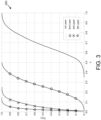
- Figure 3 is a diagram illustrating one embodiment of an empirical cumulative distribution function ("CDF") 300 of L dominant singular values of beamspace matrix.
- CDF empirical cumulative distribution function
- Figure 3 shows distribution of channel gains contained in directions of right singular vectors of the WB beamspace channel matrix H BS .
- Figure 3 verifies the distribution of channel gains by calculating the CDF of the L dominant singular values ⁇ l ( H BS ).
- a right singular vector denotes a channel direction of each transmission layer and a singular value denotes its corresponding channel gain.
- the empirical CDF 300 confirms that most gains will be contained in the direction of the first and second transmission layers and small amounts of gains will be contained in the directions of the third and fourth transmission layers.
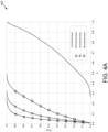
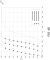
- Figures 4A-4D illustrate an empirical CDF normalized power in beam direction of selected DFT beams for each layer in a four-layer transmission.
- Figure 4A shows the CDF 405 for the first layer
- Figure 4B shows the CDF 415 for the second layer
- Figure 4C shows the CDF 425 for the third layer
- Figure 4D shows the CDF 435 for the fourth layer.
- the rank of the beamspace matrix for the r -th transmission layer is upper bounded such as rank H r BS ⁇ 2 L ⁇ r because the right singular vectors, which are quantized for the previous transmission layer ⁇ 1, ... , r - 1 ⁇ , are projected out from the beamspace matrix.
- the dimension of the beamspace matrix for the 4th transmission layer H 4 BS is 2 N rx W ⁇ 8
- efficient quantization methods may focus on a few dominant right singular vectors of the beamspace matrix.
- higher-rank CSI codebooks may be optimized by: a) exploiting more feedback overhead for first and second layers and less feedback overhead for third and fourth layers and b) focusing on a few dominant right singular vectors of beamspace matrix.
- the present disclosure develops channel compressing algorithms by considering the CSI feedback optimization criteria above.
- the first criterion may be satisfied by computing high-resolution CSI only for the first and second transmission layers.
- channel compression vectors in G r may be constructed by quantizing the L ⁇ dominant singular vectors of H r BS . Note that the compression matrix is computed independently in each layer because the matrix is layer-specific in the proposed algorithms.
- ( A ) l is the l-th column vector of the matrix A.
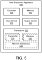
- Figure 5 depicts one embodiment of a user equipment apparatus 500 that may be used for efficiently coding a CSI codebook and preparing a codeword therefrom, according to embodiments of the disclosure.
- the user equipment apparatus 500 may be one embodiment of the remote unit 105 and/or UE 205.
- the user equipment apparatus 500 may include a processor 505, a memory 510, an input device 515, a display 520, and a transceiver 525.
- the input device 515 and the display 520 are combined into a single device, such as a touch screen.
- the user equipment apparatus 500 may not include any input device 515 and/or display 520.
- the transceiver 525 includes at least one transmitter 530 and at least one receiver 535. Additionally, the transceiver 525 may support at least one network interface 540.
- the at least one network interface 540 facilitates communication with an eNB or gNB (e.g., using the Uu interface). Additionally, the at least one network interface 540 may include an interface used for communications with a network function in the mobile core network 130, such as an N1 interface used to communicate with the AMF 135.
- the transceiver 525 is configured to communicate with a transmit-receive point ("TRP"), such as the base unit 110 and/or the gNB 210, in a radio access network using spatial multiplexing, wherein multiple transmission layers are transmitted at a time, each transmission layer comprising multiple beams.
- TRP transmit-receive point
- the processor 505 may include any known controller capable of executing computer-readable instructions and/or capable of performing logical operations.
- the processor 505 may be a microcontroller, a microprocessor, a central processing unit (“CPU"), a graphics processing unit (“GPU”), an auxiliary processing unit, a field programmable gate array (“FPGA”), or similar programmable controller.
- the processor 505 executes instructions stored in the memory 510 to perform the methods and routines described herein.
- the processor 505 is communicatively coupled to the memory 510, the input device 515, the display 520, and the transceiver 525.
- the transceiver 525 receives a set of reference signals transmitted from a TRP. From the received set of reference signals, the processor 505 selects a subset of beams from a plurality of orthogonal beams and computes one or more sets of amplitude and phase parameters for one or more channel compression matrices.
- each channel compression matrix corresponds to one transmission layer of a multiple-layer transmission.
- each channel compression matrix is comprised of one or more column vectors.
- the processor 505 controls the transceiver 525 to send the amplitude and phase parameters to a network node, such as the base unit 110 or gNB 210.
- the amplitude and phase parameters for each compression matrix are comprised of sets of amplitude and phase parameters, each set of amplitude and phase parameters parameterize in one column of a channel compression matrix.
- the number of column vectors which comprise each channel compression matrix is less than the number of beams in the selected subset of beams.
- the sets of amplitude and phase parameters include: polarization-specific amplitude coefficient parameters, polarization-specific phase coefficient parameters, and polarization amplitude offset coefficient parameters.
- the polarization-specific amplitude coefficient parameters may be in the form of one or more polarization-specific amplitude vectors
- the polarization-specific phase coefficient parameters may be in the form of one or more polarization-specific phase vectors
- the polarization amplitude offset coefficient parameters may be in the form of a polarization amplitude offset vector.
- Such sets of amplitude and phase parameters may result from the channel compressing techniques discussed below with reference to Figure 6 .
- the sets of amplitude and phase parameters include: polarization-common amplitude coefficient parameters, polarization-specific phase coefficient parameters, and polarization amplitude offset coefficient parameters.
- the polarization-common amplitude coefficient parameters may be in the form of a polarization-common amplitude vector
- the polarization-specific phase coefficient parameters may be in the form of one or more polarization-specific phase vectors
- the polarization amplitude offset coefficient parameters may be in the form of a polarization amplitude offset vector.
- Such sets of amplitude and phase parameters may result from the channel compressing techniques discussed below with reference to Figure 7 .
- the sets of amplitude and phase parameters include: polarization-common amplitude coefficient indicators, polarization-common phase coefficient indicators, polarization amplitude offset coefficient indicators, and polarization phase offset coefficient indicators.
- the polarization-common amplitude coefficient indicators may be in the form of a polarization-common amplitude vector
- the polarization-common phase coefficient indicators may be in the form of a polarization-common phase vector
- the polarization amplitude offset coefficient indicators may be in the form of a polarization applicant vector
- the polarization phase offset coefficient indicators may be in the form of a polarization phase vector.
- Such sets of amplitude and phase parameters may result from the channel compressing techniques discussed below with reference to Figure 8 .
- the largest polarization-specific amplitude coefficient of the polarization-specific amplitude coefficients for each polarization is chosen as the reference entry for that polarization and all other polarization-specific amplitude coefficients for that polarization in the subset are quantized into half-power decrease in steps relative to the reference entry.
- the largest polarization amplitude offset coefficient of the polarization amplitude offset coefficients is chosen as the reference entry and all other polarization amplitude offset coefficients are quantized into three-quarter power decreasing steps relative to the reference entry.
- the processor 505 may generate indicators of the calculates sets of amplitude and phase parameters and send the indicators to the network.
- the processor 505 controls the transceiver 525 to send the indicators corresponding to the amplitude and phase parameters to the same network node that sends the reference signals.
- the processor 505 controls the transceiver 525 to send the indicators corresponding to the amplitude and phase parameters to a different network node than the transmitter of the reference signals.
- the memory 510 in one embodiment, is a computer readable storage medium.
- the memory 510 includes volatile computer storage media.
- the memory 510 may include a RAM, including dynamic RAM (“DRAM”), synchronous dynamic RAM (“SDRAM”), and/or static RAM (“SRAM”).
- the memory 510 includes non-volatile computer storage media.
- the memory 510 may include a hard disk drive, a flash memory, or any other suitable non-volatile computer storage device.
- the memory 510 includes both volatile and non-volatile computer storage media.
- the memory 510 stores data relating to higher-rank CSI codebooks, for example beam indices, beam amplitudes, codebooks, precoding matrices, amplitude parameters, phase parameters, and the like.
- the memory 510 also stores program code and related data, such as an operating system or other controller algorithms operating on the user equipment apparatus 500 and one or more software applications.
- the input device 515 may include any known computer input device including a touch panel, a button, a keyboard, a stylus, a microphone, or the like.
- the input device 515 may be integrated with the display 520, for example, as a touchscreen or similar touch-sensitive display.
- the input device 515 includes a touchscreen such that text may be input using a virtual keyboard displayed on the touchscreen and/or by handwriting on the touchscreen.
- the input device 515 includes two or more different devices, such as a keyboard and a touch panel.
- the display 520 may include any known electronically controllable display or display device.
- the display 520 may be designed to output visual, audible, and/or haptic signals.
- the display 520 includes an electronic display capable of outputting visual data to a user.
- the display 520 may include, but is not limited to, an LCD display, an LED display, an OLED display, a projector, or similar display device capable of outputting images, text, or the like to a user.
- the display 520 may include a wearable display such as a smart watch, smart glasses, a heads-up display, or the like.
- the display 520 may be a component of a smart phone, a personal digital assistant, a television, a table computer, a notebook (laptop) computer, a personal computer, a vehicle dashboard, or the like.
- the display 520 includes one or more speakers for producing sound.
- the display 520 may produce an audible alert or notification (e.g., a beep or chime).
- the display 520 includes one or more haptic devices for producing vibrations, motion, or other haptic feedback.
- all or portions of the display 520 may be integrated with the input device 515.
- the input device 515 and display 520 may form a touchscreen or similar touch-sensitive display.
- the display 520 may be located near the input device 515.
- the transceiver 525 communicates with one or more network functions of a mobile communication network.
- the transceiver 525 operates under the control of the processor 505 to transmit messages, data, and other signals and also to receive messages, data, and other signals.
- the processor 505 may selectively activate the transceiver (or portions thereof) at particular times in order to send and receive messages.
- the transceiver 525 may include one or more transmitters 530 and one or more receivers 535. To support spatial multiplexing and/or beamforming, the transceiver 525 may include multiple transmitters 530 and/or multiple receivers 535.
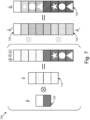
- Figure 6 depicts a graphical overview 600 of a quantization approach of a first channel compressing procedure.
- the first channel compression procedure is developed assuming that the polarization column vector for the l-th dominant beam is defined using equation 8, above:
- ⁇ l represents the power of the horizontally-polarized component of the l-th dominant beam and ⁇ l represents the power ratio of the l-th dominant beam between the different polarizations (e.g., horizontal, vertical).
- p denotes the polarization amplitude offset vector
- a a denotes the polarization-specific amplitude vector in the domain a ⁇ ⁇ h, v ⁇ (corresponding to the vertical and horizontal polarizations)
- ⁇ a denotes the polarization-specific phase vector in the domain a ⁇ ⁇ h, v ⁇ .
- p ⁇ ⁇ C 2 denotes the (unit-norm) quantized polarization amplitude offset vector
- a ⁇ a ⁇ C L denotes the (unit-norm) quantized polarization-specific amplitude vector in the domain a ⁇ ⁇ h, v ⁇ (corresponding to the vertical and horizontal polarizations)
- ⁇ a ⁇ [0, 2 ⁇ ) L denotes the quantized polarization-specific phase vector in the domain a ⁇ ⁇ h , v ⁇ .
- the structure of the channel compression vector is depicted in Figure 6 . Note that shapes within the boxes denote the amplitude of elements and shading patterns in the boxes denote the phase of elements.
- the first channel compressing procedure may include the following steps:
- Step II-1 Compute the right dominant singular vector consisting of polarization-specific sub-vectors v opt , defined as:
- the amplitude parameters are polarization-specific. Note that in each polarization, e.g., v a opt , a ⁇ ⁇ h , v ⁇ , an entry having the strongest amplitude is selected among L entries to be the reference entity.
- the selected reference entity for each polarization will be used for the amplitude quantization and they are assumed to be one. Moreover, an entry having the stronger amplitude is chosen among the two selected entries.
- the phase of the reference entry is assumed to be zero.
- the amplitude of the reference entry is assumed to be one. To simplify presentation and analysis, it is assumed that the first entry is selected as the reference entry in v opt .
- Step II-2 Quantize the polarization-specific sub-singular vectors itertively for a ⁇ ⁇ h, v ⁇ .
- the polarization-specific sub-singular vectors include polarization-specific phase sub-vectors for each polarization and polarization-specific amplitude sub-vectors for each polarization.
- the sub-vector ⁇ h 630 and the sub-vector ⁇ v 635 may be concatenated into one vector.
- the sub-vector â h 620 and the sub-vector â v 625 may be concatenated into one vector.
- Figure 7 depicts a graphical overview 700 of a quantization approach of a second channel compressing procedure.
- ⁇ l represents the amplitude difference between the different polarizations, here it is assumed that the amplitude difference is common to all beams.
- the polarization column vector for the l-th dominant beam is then defined using equation 8, above.
- p denotes the polarization amplitude offset vector
- a denotes the polarization-common amplitude vector
- ⁇ a denotes the polarization-specific phase vector in the domain a ⁇ ⁇ h, v ⁇ (corresponding to the vertical and horizontal polarizations).
- p ⁇ ⁇ C 2 denotes the (unit-norm) quantized polarization amplitude offset vector
- a ⁇ ⁇ C L denotes the (unit-norm) quantized polarization-common amplitude offset vector
- ⁇ a ⁇ [0, 2 ⁇ ) L denotes the quantized phase-specific vector in the domain a ⁇ ⁇ h, v ⁇ .
- the structure of the channel compressing vector is depicted in Figure 7 . Note that shapes within the boxes denote the amplitude of elements and shading patterns in the boxes denote the phase of elements.
- the second channel compressing procedure may include the following steps:
- Step II-1 Compute the right dominant singular vector consisting of polarization-specific sub-vectors using equation 12, above. Again, an entry having the strongest amplitude among 2 L entries in v opt is selected to be the reference entry for that polarization. The amplitude of the reference entry is assumed to be one and the phase of the reference entry is assumed to be zero. To simplify presentation and analysis, it is assumed that the first entry is selected as the reference entry in v opt .
- Step II-2 Quantize the polarization-specific sub-singular vectors a ⁇ ⁇ h, v ⁇ .
- Step II-2-A Quantize the polarization-specific phases of the sub-singular vectors ⁇ h 720 and ⁇ v 725 using equation 13, above.
- the sub-vector ⁇ h 720 and the sub-vector ⁇ v 725 may be concatenated into one vector.
- Step II-5 Update the beamspace matrix for computing the (l+1)-th channel compressing vector using equation 16, above.
- Figure 8 depicts a graphical overview 800 of a quantization approach of a third channel compressing procedure.
- ⁇ l represents the amplitude difference between the different polarizations, here it is assumed that the amplitude difference is common to all dominant beams.
- there is a constant phase difference between the different polarizations for all dominant beams here it is assumed that the amplitude difference is common to all beams.
- the polarization column vector for the l-th dominant beam may be defined using equation 8, above.
- p ⁇ ⁇ C 2 denotes the (unit-norm) quantized polarization-specific amplitude vector
- ⁇ ⁇ [0, 2 ⁇ ) 2 denotes the (unit-norm) quantized polarization-specific phase vector
- a ⁇ ⁇ C L denotes the (unit-norm) quantized polarization amplitude offset vector
- ⁇ ⁇ [0, 2 ⁇ ) L denotes the quantized phase offset vector.
- the third channel compressing procedure may include the following steps:
- the selected entry is the reference entry.
- the amplitude of the reference entry is assumed to be one and the phase of the reference entry is assumed to be zero.
- the first entry is selected as the reference entry in v reshape opt .
- Step II-3 Quantize the sub-singular vectors.
- Step II-3-B Quantize the polarization-common amplitudes of the sub-singular vector 820 using equation 27, below.
- a ⁇ argmax a ⁇ ⁇ C amp L v reshape opt H a ⁇ ⁇ a ⁇ ⁇ 2 ⁇ e j ⁇ ⁇ 2 ⁇ C L
- the dominant polarization is selected between horizontal and vertical polarizations.
- the phases for the dominant polarization is assumed to be zero in Z B phase and the amplitudes for the dominant polarization is assumed to be one in Z B pol , amp .
- Step II-6 Update the beamspace matrix for computing the (l+1)-th channel compressing vector using equation 16.
- the channel compression vectors in the channel compression matrix G r are semi-orthogonal (e.g., not perfectly orthogonal) because it may not be possible to properly quantize the right singular vectors of H r comp .
- To compute the Type II CSI by considering the semi-orthogonal property of the channel compressing matrix compute a L ⁇ -dimensional (unit norm) basis combining vector w ⁇ in SB, which maximizes the argument H r BS G r w ⁇ ⁇ G r w ⁇ ⁇ 2 2 .
- Figure 9 illustrates an algorithm 900 for a wideband quantizer based on a channel compressing procedure, according to embodiments of the disclosure.
- a WB quantizer Based on the proposed channel compression algorithm, the beamspace matrix is compressed with G r , as shown in the line 3 of the wideband quantizer algorithm 900.
- WB PMI we should quantize the L ⁇ -dimensional right singular vector of the compressed channel matrix in equation 6, instead of quantizing the 2 L -dimensional right singular vector of the beamspace channel matrix, as proposed in the current Type II codebook.
- the target combining vector may be computed based on the derivation in equation 31, as summarized in the line 4 of the wideband quantizer algorithm.
- the amplitudes of the L ⁇ -dimensional target basis combining vector may then be quantized.
- the details of the vector quantization technique are summarized in the lines 5-6 of the wideband quantizer algorithm 900.
- the quantized basis combining vector w r is the L ⁇ -dimensional column vector, while the dimension of the beamspace matrix H r BS is 2 N rx W ⁇ 2 L.
- the compressed combining vector w r should be expanded to v r , as proposed in the line 7 of the wideband quantizer algorithm 900.
- the beamspace matrix for the following transmission layer is then updated by projecting out v r from the H r BS , as shown in the line 8 of the wideband quantizer algorithm 900.
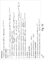
- Figure 10 illustrates an algorithm for a subband quantizer based on a channel compressing procedure, according to embodiments of the disclosure.
- SB quantizer We next develop SB quantizer and the details are summarized in the subband quantizer algorithm 1000. Because compressing vectors in G r are not perfectly orthogonal, the target combining vector may be computed based on the derivation in equation 30, as in the line 4 of the subband quantizer algorithm 1000.
- the quantized basis combining vector w r [ s ] is the L ⁇ -dimensional column vector, while the dimension of the beamspace matrix H r BS s is 2 N rx W / S ⁇ 2 L .
- the compressed combining vector w r [ s ] should be expanded to v r [ s ] , as shown in the line 8 of the subband quantizer algorithm 1000.
- the beamspace matrix for the following transmission layer is then updated by projecting out v r [ s ] from the H r BS s , , as shown in the line 8 of the subband quantizer algorithm 1000.
- the transmitter After collecting WB and SB PMI from users, the transmitter computes beamforming vectors. Note that the details are summarized in lines 13-14 of the subband quantizer algorithm 1000.
- the proposed quantizers may be operated in conjunction with the current Type II CSI codebook.
- WB and SB PMI for rank 1-2 beamformers are computed based on the Type II codebook while that for rank 3-4 beamformers may be computed based on the proposed CSI quantizers in Algorithms 900 and 1000.
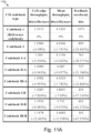
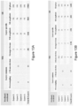
- Figures 11A and 12A are diagrams illustrating data rate performance of CSI codebooks, according to embodiments of the disclosure.
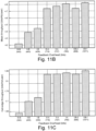
- Figures 11B and 12B are diagrams illustrating mean throughput performance of CSI codebooks, according to embodiments of the disclosure.
- Figures 11C and 12C are diagrams illustrating cell-edge throughput performance of CSI codebooks, according to embodiments of the disclosure.
- the codebook 1 (reference codebook) is developed based on the Type II CSI codebook in 3GPP R1-1709232 and the codebook 2 is proposed in 3GPP R1-1710674.
- the codebooks I, II, and III are developed based on the first channel compressing method, the second channel compressing method, and the third channel compressing method, respectively. For numerical simulations, system level simulations are conducted with 40 drops and 15,000 TTIs.
- the cell-edge and mean throughput results are presented in Figures 11A and 12A .
- the codebooks are organized in an ascending order of the total feedback overhead.
- the codebook 1 (reference codebook) provides the best cell-edge and mean throughput at the expense of exorbitant feedback overhead.
- the cell-edge mean throughput performances of the proposed codebook III-A are similar to that of codebook 2 in 3GPP R1-1710674, while the feedback overhead the proposed codebook III-A is much lesser than that of codebook 2.
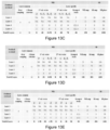
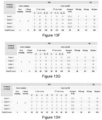
- Figures 13A-H illustrate feedback overhead for varies codebooks, according to embodiments disclosure.
- Figure 14 depicts a method 1400 for efficiently coding a CSI codebook and preparing a codeword therefrom, according to embodiments of the disclosure.
- the method 1400 is performed by an apparatus, such as the remote unit 105, the UE 205, and/or the user equipment apparatus 500.
- the method 1400 may be performed by a processor executing program code, for example, a microcontroller, a microprocessor, a CPU, a GPU, an auxiliary processing unit, a FPGA, or the like.
- the method 1400 begins with receiving 1405 a set of reference signals transmitted from a transmission point.
- the transmission point may be a network entity in a radio access network, such as the base unit 110 and/or the gNB 210.
- the method 1400 includes selecting 1410 a subset of beams from a plurality of orthogonal beams.
- the method 1400 includes computing 1415 sets of amplitude and phase parameters for one or more channel compression matrices.
- each channel compression matrix corresponds to one transmission layer of the multiple-layer transmission.
- each channel compression matrix is comprised of one or more column vectors.
- the method 1400 includes sending 1420 the amplitude and phase parameters to a network node.
- the network node may be a base station, such as the base unit 110 and/or the gNB 210.
- the method 1400 ends.
- the first apparatus may be a wireless device, such as a remote unit 105, the UE 205, and/or user equipment apparatus 500.
- the first apparatus includes a transceiver that receives a set of reference signals transmitted from a transmission point.
- the transmission point may be a network entity in a radio access network, such as the base unit 110 and/or the gNB 210.
- the first apparatus includes a processor that selects a subset of beams from a plurality of orthogonal beams based on the received set of reference signals.
- the processor computes a plurality of sets of amplitude and phase parameters for one or more channel compression matrices, wherein each channel compression matrix corresponds to one transmission layer of a multiple-layer transmission, and wherein each channel compression matrix is comprised of one or more column vectors.
- the processor controls the radio transceiver to send indications of the sets of amplitude and phase parameters.
- each channel compression matrix is less than the number of beams in the selected subset of beams.
- each set of amplitude and phase parameters parameterizes one column of the channel compression matrix.
- the sets of amplitude and phase parameters include a set of polarization-specific amplitude coefficient parameters, a set of polarization-specific phase coefficient parameters, and a set of polarization amplitude coefficient parameters.
- the polarization-specific amplitude coefficient parameters form a polarization-specific amplitude vector
- the polarization-specific phase coefficient parameters form a polarization-specific phase vector
- the polarization amplitude offset coefficient parameters form a polarization amplitude vector.
- the processor may identify a largest polarization-specific amplitude coefficient parameter of the polarization-specific amplitude coefficient parameters for each polarization.
- the largest polarization-specific amplitude coefficient parameter becomes a reference entry for that polarization.
- the processor may further quantize, for each polarization, all other polarization-specific amplitude coefficient parameters for that polarization relative to the reference entry for that polarization.
- the processor may identify a largest polarization amplitude offset coefficient parameter of the polarization amplitude offset coefficient parameters for each polarization.
- the largest polarization amplitude offset coefficient parameter becomes a reference entry for that polarization.
- the processor may further quantize, for each polarization, all other polarization amplitude offset coefficient parameters for that polarization relative to the reference entry for that polarization.
- the sets of amplitude and phase parameters include a set of polarization-common amplitude coefficient parameters, a set of polarization-specific phase coefficient parameters, and a set of polarization amplitude offset coefficient parameters.
- the polarization-common amplitude coefficient parameters form a polarization-common amplitude vector
- the polarization-specific phase coefficient parameters form a polarization-specific phase vector
- the polarization amplitude offset coefficient parameters form a polarization amplitude vector.
- the processor may identify a largest polarization-common amplitude coefficient parameter of the polarization-common amplitude coefficient parameters for each polarization.
- the largest polarization-common amplitude coefficient parameter becomes a reference entry for that polarization.
- the processor may further quantize, for each polarization, all other polarization-common amplitude coefficient parameters for that polarization relative to the reference entry for that polarization.
- the processor may identify a largest polarization amplitude offset coefficient parameter of the polarization amplitude offset coefficient parameters for each polarization.
- the largest polarization amplitude offset coefficient parameter becomes a reference entry for that polarization.
- the processor may further quantize, for each polarization, all other polarization amplitude offset coefficient parameters for that polarization relative to the reference entry for that polarization.
- the sets of amplitude and phase parameters include a set of polarization-common amplitude coefficient parameters, a set of polarization-common phase coefficient parameters, a set of polarization amplitude offset coefficient parameters, and a set of polarization phase offset coefficient parameters.
- the polarization-common amplitude coefficient parameters form a polarization-common amplitude vector
- the polarization-common phase coefficient parameters form a polarization-common phase vector
- the polarization amplitude offset coefficient parameters form a polarization amplitude vector
- the polarization phase offset coefficient parameters form a polarization phase vector.
- the processor may identify a largest polarization-common amplitude coefficient parameter of the polarization-common amplitude coefficient parameters for each polarization.
- the largest polarization-common amplitude coefficient parameter becomes a reference entry for that polarization.
- the processor may further quantize, for each polarization, all other polarization-common amplitude coefficient parameters for that polarization relative to the reference entry for that polarization.
- the processor may identify a largest polarization amplitude offset coefficient parameter of the polarization amplitude offset coefficient parameters for each polarization.
- the largest polarization amplitude offset coefficient parameter becomes a reference entry for that polarization.
- the processor may further quantize, for each polarization, all other polarization amplitude offset coefficient parameters for that polarization relative to the reference entry for that polarization.
- the first method may be performed by a wireless device, such as a remote unit 105, the UE 205, and/or user equipment apparatus 500.
- the first method includes receiving a set of reference signals transmitted from a network entity in a wireless communication system and selecting a subset of beams from a plurality of orthogonal beams based on the received set of reference signals.
- the network entity may be a transmission point in a radio access network, such as the base unit 110 and/or the gNB 210.
- the first method includes computing sets of amplitude and phase parameters for one or more channel compression matrices, wherein each channel compression matrix corresponds to one transmission layer of a multiple-layer transmission, and wherein each channel compression matrix is composed of one or more column vectors.
- the method includes sending indications of the sets of amplitude and phase parameters.
- each channel compression matrix is less than the number of beams in the selected subset of beams.
- each set of amplitude and phase parameters parameterizes one column of the channel compression matrix.
- the sets of amplitude and phase parameters include a set of polarization-specific amplitude coefficient parameters, a set of polarization-specific phase coefficient parameters, and a set of polarization amplitude offset coefficient parameters.
- the polarization-specific amplitude coefficient parameters form a polarization-specific amplitude vector
- the polarization-specific phase coefficient parameters form a polarization-specific phase vector
- the polarization amplitude offset coefficient parameters form a polarization amplitude vector.
- the first method may include identifying a largest polarization-specific amplitude coefficient parameter of the polarization-specific amplitude coefficient parameters for each polarization.
- the largest polarization-specific amplitude coefficient parameter becomes a reference entry for that polarization.
- the first method further includes quantizing, for each polarization, all other polarization-specific amplitude coefficient parameters for that polarization relative to the reference entry for that polarization.
- the first method may include identifying a largest polarization amplitude offset coefficient parameter of the polarization amplitude offset coefficient parameters for each polarization.
- the largest polarization amplitude offset coefficient parameter becomes a reference entry for that polarization.
- the first method further includes quantizing, for each polarization, all other polarization amplitude offset coefficient parameters for that polarization relative to the reference entry for that polarization.
- the sets of amplitude and phase parameters include a set of polarization-common amplitude coefficient parameters, a set of polarization-specific phase coefficient parameters, and a set of polarization amplitude offset coefficient parameters.
- the polarization-common amplitude coefficient parameters form a polarization-common amplitude vector
- the polarization-specific phase coefficient parameters form a polarization-specific phase vector
- the polarization amplitude offset coefficient parameters form a polarization amplitude vector.
- the first method may include identifying a largest polarization-common amplitude coefficient parameter of the polarization-common amplitude coefficient parameters for each polarization.
- the largest polarization-common amplitude coefficient parameter becomes a reference entry for that polarization.
- the first method further includes quantizing, for each polarization, all other polarization-common amplitude coefficient parameters for that polarization relative to the reference entry for that polarization.
- the first method may include identifying a largest polarization amplitude offset coefficient parameter of the polarization amplitude offset coefficient parameters for each polarization.
- the largest polarization amplitude offset coefficient parameter becomes a reference entry for that polarization.
- the first method further includes quantizing, for each polarization, all other polarization amplitude offset coefficient parameters for that polarization relative to the reference entry for that polarization.
- the sets of amplitude and phase parameters include a set of polarization-common amplitude coefficient parameters, a set of polarization-common phase coefficient parameters, a set of polarization amplitude offset coefficient parameters, and a set of polarization phase offset coefficient parameters.
- the polarization-common amplitude coefficient parameters form a polarization-common amplitude vector
- the polarization-common phase coefficient parameters form a polarization-common phase vector
- the polarization amplitude offset coefficient parameters form a polarization amplitude vector
- the polarization phase offset coefficient parameters form a polarization phase vector.
- the first method may include identifying a largest polarization-common amplitude coefficient parameter of the polarization-common amplitude coefficient parameters for each polarization.
- the largest polarization-common amplitude coefficient parameter becomes a reference entry for that polarization.
- the first method further includes quantizing, for each polarization, all other polarization-common amplitude coefficient parameters for that polarization relative to the reference entry for that polarization.
- the first method may include identifying a largest polarization amplitude offset coefficient parameter of the polarization amplitude offset coefficient parameters for each polarization.
- the largest polarization amplitude offset coefficient parameter becomes a reference entry for that polarization.
- the first method further includes quantizing, for each polarization, all other polarization amplitude offset coefficient parameters for that polarization relative to the reference entry for that polarization.
Landscapes
- Engineering & Computer Science (AREA)
- Computer Networks & Wireless Communication (AREA)
- Signal Processing (AREA)
- Life Sciences & Earth Sciences (AREA)
- Environmental Sciences (AREA)
- Mobile Radio Communication Systems (AREA)
- Radio Transmission System (AREA)
Abstract
Description
- This application claims priority to
United States Provisional Patent Application Number 62/619/670 entitled "Efficient Recovery from Beam Failure" and filed on January 19, 2018 for Jiho Song and Tyler Brown - The subject matter disclosed herein relates generally to wireless communications and more particularly relates to efficiently providing high-resolution CSI feedback.
- The following abbreviations are herewith defined, at least some of which are referred to within the following description.
- The following abbreviations are herewith defined, at least some of which are referred to within the following description: Third Generation Partnership Project ("3GPP"), Fifth-Generation Core ("5GC"), Access and Mobility Management Function ("AMF"), Access Point Name ("APN"), Access Stratum ("AS"), Bandwidth Adaptation ("BA"), Bandwidth Part ("BWP"), Block Error Rate ("BLER"), Carrier Aggregation ("CA"), Cell-Specific Radio Network Temporary Identifier ("C-RNTI"), Clear Channel Assessment ("CCA"), Cyclic Prefix ("CP"), Control Element ("CE"), Cyclical Redundancy Check ("CRC"), Channel State Information ("CSI"), Common Search Space ("CSS"), Data Radio Bearer ("DRB," e.g., carrying user plane data), Demodulation Reference Signal ("DM-RS"), Discrete Fourier Transform Spread ("DFTS"), Downlink Control Information ("DCI"), Downlink ("DL"), Downlink Pilot Time Slot ("DwPTS"), Enhanced Clear Channel Assessment ("eCCA"), Evolved Node B ("eNB"), Evolved Packet Core ("EPC"), Evolved UMTS Terrestrial Radio Access Network ("E-UTRAN"), Frame Based Equipment ("FBE"), Frequency Division Duplex ("FDD"), Frequency Division Multiple Access ("FDMA"), Frequency Division Orthogonal Cover Code ("FD-OCC"), Guard Period ("GP"), General Packet Radio Service ("GPRS"), Global System for Mobile Communications ("GSM"), Load Based Equipment ("LBE"), Listen-Before-Talk ("LBT"), Logical Channel ("LCH"), Long Term Evolution ("LTE"), Multiple Access ("MA"), Medium Access Control ("MAC"), Master Cell Group ("MCG"), Modulation Coding Scheme ("MCS"), Mobility Management Entity ("MME"), Multiple Input Multiple Output ("MIMO"), Multi User Shared Access ("MUSA"), Narrowband ("NB"), Next Generation (e.g., 5G) Node-B ("gNB"), Next Generation Radio Access Network ("NG-RAN"), New Radio ("NR", e.g., 5G radio access), Non-Orthogonal Multiple Access ("NOMA"), Orthogonal Frequency Division Multiplexing ("OFDM"), Packet Data Convergence Protocol ("PDCP"), Primary Cell ("PCell"), Physical Broadcast Channel ("PBCH"), Packet Data Network ("PDN"), Protocol Data Unit ("PDU"), Physical Downlink Control Channel ("PDCCH"), Physical Downlink Shared Channel ("PDSCH"), Pattern Division Multiple Access ("PDMA"), Physical Hybrid ARQ Indicator Channel ("PHICH"), Physical Random Access Channel ("PRACH"), Physical Resource Block ("PRB"), Physical Uplink Control Channel ("PUCCH"), Physical Uplink Shared Channel ("PUSCH"), Quality of Service ("QoS"), Quadrature Phase Shift Keying ("QPSK"), Radio Link Control ("RLC"), Radio Link Failure ("RLF"), Radio Link Monitoring ("RLM"), Radio Resource Control ("RRC"), Random-Access Procedure ("RACH"), Random Access Response ("RAR"), Radio Network Temporary Identifier ("RNTI"), Reference Signal ("RS"), Reference Signal Received Power ("RSRP"), Remaining Minimum System Information ("RMSI"), Resource Block Assignment ("RBA"), Resource Spread Multiple Access ("RSMA"), Round Trip Time ("RTT"), Receive ("RX"), Sparse Code Multiple Access ("SCMA"), Signaling Radio Bearer ("SRB," e.g., carrying control plane data), Single Carrier Frequency Division Multiple Access ("SC-FDMA"), Secondary Cell ("SCell"), Secondary Cell Group ("SCG"), Shared Channel ("SCH"), Signal-to-Interference-Plus-Noise Ratio ("SINR"), Serving Gateway ("SGW"), Service Data Unit ("SDU"), Sequence Number ("SN"), Session Management Function ("SMF"), System Information Block ("SIB"), Synchronization Signal ("SS"), Transport Block ("TB"), Transport Block Size ("TBS"), Time-Division Duplex ("TDD"), Time Division Multiplex ("TDM"), Time Division Orthogonal Cover Code ("TD-OCC"), Transmission Time Interval ("TTI"), Transmit ("TX"), Uplink Control Information ("UCI"), User Entity/Equipment (Mobile Terminal) ("the UE"), Uplink ("UL"), User Plane ("UP"), Universal Mobile Telecommunications System ("UMTS"), Uplink Pilot Time Slot ("UpPTS"), Wireless Local Area Network ("WLAN"), and Worldwide Interoperability for Microwave Access ("WiMAX").
- In an effort to enhance system performance in 3GPP networks, more recent standards have looked at different forms of spatial diversity including different forms of multiple input multiple output (MIMO) systems, which involve the use of multiple antennas at each of the source and the destination of the wireless communication for multiplying the capacity of the radio link through the use of multipath propagation. Such a system makes increasingly possible the simultaneous transmission and reception of more than one data signal using the same radio channel.
- As part of supporting MIMO communications, user equipment can make use of channel state information codebooks, which help to define the nature of the adopted beams, which are used to support a particular data connection. Higher rank codebooks can sometimes be used to enhance system performance, but often at the price of an increase in the amount of feedback overhead. In 3GPP networks, a high-resolution channel state information ("CSI") codebook, e.g., Type II CSI codebook is used to support full-dimension ("FD") multiple-input multiple-output ("MIMO') systems. Through system-level simulations, it is verified that the rank 1-2 Type II CSI codebook provides improved data-rate performance compared to
previous Release 14 CSI codebooks. - Although the rank 1-2 Type II CSI codebook shows improved data-rate throughput, it is necessary to support higher-rank transmission to exploit the full benefits of multiplexing gain and multiuser diversity gain. Moreover, it is required to compute high-resolution CSI to suppress inter-layer and inter-user interferences effectively.
- Methods for efficiently providing high-resolution CSI feedback are disclosed. Apparatuses and systems also perform the functions of the methods.
- One method (e.g., performed by a UE) for efficiently providing high-resolution CSI feedback includes receiving a set of reference signals transmitted from a network entity in a wireless communication system and selecting a subset of beams from a plurality of orthogonal beams based on the received set of reference signals. The method includes computing sets of amplitude and phase parameters for one or more channel compression matrices, wherein each channel compression matrix corresponds to one transmission layer of a multiple-layer transmission and wherein each channel compression matrix is composed of one or more column vectors. The method includes sending indications of the sets of amplitude and phase parameters.
- A more particular description of the embodiments briefly described above will be rendered by reference to specific embodiments that are illustrated in the appended drawings. Understanding that these drawings depict only some embodiments and are not therefore to be considered to be limiting of scope, the embodiments will be described and explained with additional specificity and detail through the use of the accompanying drawings, in which:
-
Figure 1 is a schematic block diagram illustrating one embodiment of a wireless communication system for efficiently providing high-resolution CSI feedback; -
Figure 2 illustrates one embodiment of a network architecture for efficiently providing high-resolution CSI feedback; -
Figure 3 is a diagram illustrating one embodiment of an empirical cumulative distribution function ("CDF") of L dominant singular values of beamspace matrix; -
Figures 4A is a diagram illustrating one embodiment of an empirical CDF normalized power in beam direction of selected DFT beams for a first layer of a multi-layer transmission; -
Figure 4B is a diagram illustrating one embodiment of an empirical CDF normalized power in beam direction of selected DFT beams for a second layer of a multi-layer transmission; -
Figure 4C is a diagram illustrating one embodiment of an empirical CDF normalized power in beam direction of selected DFT beams for a third layer of a multi-layer transmission; -
Figure 4D is a diagram illustrating one embodiment of an empirical CDF normalized power in beam direction of selected DFT beams for a fourth layer of a multi-layer transmission; -
Figure 5 is a schematic block diagram illustrating one embodiment of a user equipment apparatus for efficiently providing high-resolution CSI feedback; -
Figure 6 is a diagram illustrating a graphical overview of a quantization approach of a first channel compressing procedure; -
Figure 7 is a diagram illustrating one embodiment of a graphical overview of a quantization approach of a second channel compressing procedure; -
Figure 8 is a diagram illustrating one embodiment of a graphical overview of a quantization approach of a third channel compressing procedure; -
Figure 9 is a diagram illustrating one embodiment of an algorithm for a wideband quantizer based on a channel compressing procedure; -
Figure 10 is a diagram illustrating one embodiment of an algorithm for a subband quantizer based on a channel compressing procedure; -
Figure 11A is a diagram illustrating one embodiment of data rate performance of CSI codebooks for λtraffic = 3.5; -
Figure 11B is a diagram illustrating one embodiment of mean throughput performance of CSI codebooks for λtraffic = 3.5; -
Figure 11C is a diagram illustrating one embodiment of cell-edge throughput performance of CSI codebooks for λtraffic = 3.5; -
Figure 12A is a diagram illustrating another embodiment of data rate performance of CSI codebooks for λtraffic = 2.0; -
Figure 12B is a diagram illustrating another embodiment of mean throughput performance of CSI codebooks for λtraffic = 2.0; -
Figure 12C is a diagram illustrating another embodiment of cell-edge throughput performance of CSI codebooks for λtraffic = 2.0; -
Figure 13A is a diagram illustrating one embodiment of feedback overhead for aCodebook 1 for rank 1-4 transmissions; -
Figure 13B is a diagram illustrating one embodiment of feedback overhead for aCodebook 2 for rank 1-4 transmissions; -
Figure 13C is a diagram illustrating one embodiment of feedback overhead for a Codebook I-A for rank 1-4 transmissions; -
Figure 13D is a diagram illustrating one embodiment of feedback overhead for a Codebook II-A for rank 1-4 transmissions; -
Figure 13E is a diagram illustrating one embodiment of feedback overhead for a Codebook III-A for rank 1-4 transmissions; -
Figure 13F is a diagram illustrating one embodiment of feedback overhead for a Codebook I-B for rank 1-4 transmissions; -
Figure 13G is a diagram illustrating one embodiment of feedback overhead for a Codebook II-B for rank 1-4 transmissions; -
Figure 13H is a diagram illustrating one embodiment of feedback overhead for a Codebook III-B for rank 1-4 transmissions; and -
Figure 14 is a schematic flow chart diagram illustrating one embodiment of a method for efficiently providing high-resolution CSI feedback. - Throughout this disclosure,denotes the field of complex numbers,
 denotes the field of real numbers, ∥ ▪ ∥ p is the p-norm, ∥ ▪ ∥ F is the Frobenius norm, ⊙ is the Hadamard product, ⊗ is the Kronecker product, a H is the conjugate transpose of the column vector a, 0 a×b is the a×b all zeros matrix, I N is the N×N identity matrix,


- As will be appreciated by one skilled in the art, aspects of the embodiments may be embodied as a system, apparatus, method, or program product. Accordingly, embodiments may take the form of an entirely hardware embodiment, an entirely software embodiment (including firmware, resident software, micro-code, etc.) or an embodiment combining software and hardware aspects.
- For example, the disclosed embodiments may be implemented as a hardware circuit comprising custom very-large-scale integration ("VLSI") circuits or gate arrays, off-the-shelf semiconductors such as logic chips, transistors, or other discrete components. The disclosed embodiments may also be implemented in programmable hardware devices such as field programmable gate arrays, programmable array logic, programmable logic devices, or the like. As another example, the disclosed embodiments may include one or more physical or logical blocks of executable code which may, for instance, be organized as an object, procedure, or function.
- Furthermore, embodiments may take the form of a program product embodied in one or more computer readable storage devices storing machine readable code, computer readable code, and/or program code, referred hereafter as code. The storage devices may be tangible, non-transitory, and/or non-transmission. The storage devices may not embody signals. In a certain embodiment, the storage devices only employ signals for accessing code.
- Any combination of one or more computer readable medium may be utilized. The computer readable medium may be a computer readable storage medium. The computer readable storage medium may be a storage device storing the code. The storage device may be, for example, but not limited to, an electronic, magnetic, optical, electromagnetic, infrared, holographic, micromechanical, or semiconductor system, apparatus, or device, or any suitable combination of the foregoing.
- More specific examples (a non-exhaustive list) of the storage device would include the following: an electrical connection having one or more wires, a portable computer diskette, a hard disk, a random-access memory ("RAM"), a read-only memory ("ROM"), an erasable programmable read-only memory ("EPROM" or Flash memory), a portable compact disc read-only memory ("CD-ROM"), an optical storage device, a magnetic storage device, or any suitable combination of the foregoing. In the context of this document, a computer readable storage medium may be any tangible medium that can contain or store a program for use by or in connection with an instruction execution system, apparatus, or device.
- Code for carrying out operations for embodiments may be any number of lines and may be written in any combination of one or more programming languages including an obj ect-oriented programming language such as Python, Ruby, Java, Smalltalk, C++, or the like, and conventional procedural programming languages, such as the "C" programming language, or the like, and/or machine languages such as assembly languages. The code may execute entirely on the user's computer, partly on the user's computer, as a stand-alone software package, partly on the user's computer and partly on a remote computer or entirely on the remote computer or server. In the latter scenario, the remote computer may be connected to the user's computer through any type of network, including a local area network ("LAN") or a wide area network ("WAN"), or the connection may be made to an external computer (for example, through the Internet using an Internet Service Provider).
- Reference throughout this specification to "one embodiment," "an embodiment," or similar language means that a particular feature, structure, or characteristic described in connection with the embodiment is included in at least one embodiment. Thus, appearances of the phrases "in one embodiment," "in an embodiment," and similar language throughout this specification may, but do not necessarily, all refer to the same embodiment, but mean "one or more but not all embodiments" unless expressly specified otherwise. The terms "including," "comprising," "having," and variations thereof mean "including but not limited to," unless expressly specified otherwise. An enumerated listing of items does not imply that any or all of the items are mutually exclusive, unless expressly specified otherwise. The terms "a," "an," and "the" also refer to "one or more" unless expressly specified otherwise.
- Furthermore, the described features, structures, or characteristics of the embodiments may be combined in any suitable manner. In the following description, numerous specific details are provided, such as examples of programming, software modules, user selections, network transactions, database queries, database structures, hardware modules, hardware circuits, hardware chips, etc., to provide a thorough understanding of embodiments. One skilled in the relevant art will recognize, however, that embodiments may be practiced without one or more of the specific details, or with other methods, components, materials, and so forth. In other instances, well-known structures, materials, or operations are not shown or described in detail to avoid obscuring aspects of an embodiment.
- Aspects of the embodiments are described below with reference to schematic flowchart diagrams and/or schematic block diagrams of methods, apparatuses, systems, and program products according to embodiments. It will be understood that each block of the schematic flowchart diagrams and/or schematic block diagrams, and combinations of blocks in the schematic flowchart diagrams and/or schematic block diagrams, can be implemented by code. This code may be provided to a processor of a general-purpose computer, special purpose computer, or other programmable data processing apparatus to produce a machine, such that the instructions, which execute via the processor of the computer or other programmable data processing apparatus, create means for implementing the functions/acts specified in the flowchart diagrams and/or block diagrams.
- The code may also be stored in a storage device that can direct a computer, other programmable data processing apparatus, or other devices to function in a particular manner, such that the instructions stored in the storage device produce an article of manufacture including instructions which implement the function/act specified in the flowchart diagrams and/or block diagrams.
- The code may also be loaded onto a computer, other programmable data processing apparatus, or other devices to cause a series of operational steps to be performed on the computer, other programmable apparatus or other devices to produce a computer implemented process such that the code which execute on the computer or other programmable apparatus provide processes for implementing the functions/acts specified in the flowchart diagrams and/or block diagrams.
- The flowchart diagrams and/or block diagrams in the Figures illustrate the architecture, functionality, and operation of possible implementations of apparatuses, systems, methods, and program products according to various embodiments. In this regard, each block in the flowchart diagrams and/or block diagrams may represent a module, segment, or portion of code, which includes one or more executable instructions of the code for implementing the specified logical function(s).
- It should also be noted that, in some alternative implementations, the functions noted in the block may occur out of the order noted in the Figures. For example, two blocks shown in succession may, in fact, be executed substantially concurrently, or the blocks may sometimes be executed in the reverse order, depending upon the functionality involved. Other steps and methods may be conceived that are equivalent in function, logic, or effect to one or more blocks, or portions thereof, of the illustrated Figures.
- Although various arrow types and line types may be employed in the flowchart and/or block diagrams, they are understood not to limit the scope of the corresponding embodiments. Indeed, some arrows or other connectors may be used to indicate only the logical flow of the depicted embodiment. For instance, an arrow may indicate a waiting or monitoring period of unspecified duration between enumerated steps of the depicted embodiment. It will also be noted that each block of the block diagrams and/or flowchart diagrams, and combinations of blocks in the block diagrams and/or flowchart diagrams, can be implemented by special purpose hardware-based systems that perform the specified functions or acts, or combinations of special purpose hardware and code.
- The description of elements in each figure may refer to elements of proceeding figures. Like numbers refer to like elements in all figures, including alternate embodiments of like elements.
- In order to fully exploit the benefits of multiuser (MU) full-dimension (FD) multiple-input multiple-output (MIMO) systems, it is necessary to support higher rank MU transmission to benefit from multiplexing gain and multiuser diversity gain. Moreover, it is required to compute high-resolution channel state information (CSI) to effectively suppress inter-layer and inter-user interferences. The present disclosure describes a high-resolution CSI codebook that can support higher rank transmission (e.g., rank 1-4 transmission) with less feedback overhead compared to the previously reported CSI codebooks.
- Previously reported Type II codebook (e.g., for rank 1-2 transmission scenario) give improved data-rate performances compared to
3GPP Rel 14 codebooks, although at the cost of a large total feedback overhead. Extending the current rank 1-2 Type II codebook to rank 1-4 transmission scenario increases the system performances at the cost of huge feedback overhead, which is not practical. The simple extension of the current Type II codebook would cause a huge burden on feedback links because the feedback overhead increases proportionally to the number of maximum transmission ranks. To provide increases system performance while reducing feedback overhead, the present disclosure describes channel compressing techniques and suitable CSI quantizers providing a practical high-resolution CSI codebook supporting rank 1-4 transmissions. -
Figure 1 depicts awireless communication system 100 for efficiently providing high-resolution CSI feedback, according to embodiments of the disclosure. In one embodiment, thewireless communication system 100 includes at least oneremote unit 105, anaccess network 120 containing at least onebase unit 110,wireless communication links 115, and amobile core network 130. Theaccess network 120 andmobile core network 130 form a mobile communication network. Even though a specific number ofremote units 105,access networks 120,base units 110,wireless communication links 115, andmobile core networks 130 are depicted inFigure 1 , one of skill in the art will recognize that any number ofremote units 105,access networks 120,base units 110,wireless communication links 115, andmobile core networks 130 may be included in thewireless communication system 100. In another embodiment, theaccess network 120 contains one or more WLAN (e.g., Wi-Fi™) access points. - In one implementation, the
wireless communication system 100 is compliant with the 5G system specified in the 3GPP specifications (e.g., "5G NR"). More generally, however, thewireless communication system 100 may implement some other open or proprietary communication network, for example, LTE or WiMAX, among other networks. Network environments often involve one or more sets of standards, which each define various aspects of any communication connection being made when using the corresponding standard within the network environment. Examples of developing and/or existing standards include new radio access technology (NR), Long Term Evolution (LTE), Universal Mobile Telecommunications Service (UMTS), Global System for Mobile Communication (GSM), and/or Enhanced Data GSM Environment (EDGE). The present disclosure is not intended to be limited to the implementation of any particular wireless communication system architecture or protocol. - In one embodiment, the
remote units 105 may include computing devices, such as desktop computers, laptop computers, personal digital assistants ("PDAs"), tablet computers, smart phones, smart televisions (e.g., televisions connected to the Internet), smart appliances (e.g., appliances connected to the Internet), set-top boxes, game consoles, security systems (including security cameras), vehicle on-board computers, network devices (e.g., routers, switches, modems), or the like. In some embodiments, theremote units 105 include wearable devices, such as smart watches, fitness bands, optical head-mounted displays, or the like. Moreover, theremote units 105 may be referred to as the UEs, subscriber units, mobiles, mobile stations, users, terminals, mobile terminals, fixed terminals, subscriber stations, user terminals, wireless transmit/receive unit ("WTRU"), a wireless device, or by other terminology used in the art. - The
remote units 105 may communicate directly with one or more of thebase units 110 in theaccess network 120 via uplink ("UL") and downlink ("DL") communication signals. Furthermore, the UL and DL communication signals may be carried over the wireless communication links 115. Here, theaccess network 120 is an intermediate network that provides theremote units 105 with access to services in themobile core network 130. - The
base units 110 may be distributed over a geographic region. In certain embodiments, abase unit 110 may also be referred to as an access terminal, an access point, a base, a base station, a Node-B, an eNB, a gNB, a Home Node-B, a relay node, a device, or by any other terminology used in the art. Thebase units 110 are generally part of a radio access network ("RAN"), such as theaccess network 120, that may include one or more controllers communicably coupled to one or morecorresponding base units 110. These and other elements of the radio access network are not illustrated, but are well known generally by those having ordinary skill in the art. Thebase units 110 connect to themobile core network 130 via theaccess network 120. - The
base units 110 may serve a number ofremote units 105 within a serving area, for example, a cell or a cell sector via awireless communication link 115. Thebase units 110 may communicate directly with one or more of theremote units 105 via communication signals. Generally, thebase units 110 transmit downlink ("DL") communication signals to serve theremote units 105 in the time, frequency, and/or spatial domain. Furthermore, the DL communication signals may be carried over the wireless communication links 115. Thewireless communication links 115 may be any suitable carrier in licensed or unlicensed radio spectrum. Thewireless communication links 115 facilitate communication between one or more of theremote units 105 and/or one or more of thebase units 110. - In one embodiment, the
mobile core network 130 is a 5G core ("5GC") or the evolved packet core ("EPC"), which may be coupled toother data network 125, like the Internet and private data networks, among other data networks. Eachmobile core network 130 belongs to a single public land mobile network ("PLMN"). The present disclosure is not intended to be limited to the implementation of any particular wireless communication system architecture or protocol. - The
mobile core network 130 includes several network functions ("NFs"). As depicted, themobile core network 130 includes an access and mobility management function ("AMF") 13 5, a session management function ("SMF") 140, and a user plane function ("UPF") 145. TheAMF 135 provides services such as UE registration, UE connection management, and UE mobility management. TheSMF 140 manages the data sessions of theremote units 105, such as a PDU session. TheUPF 145 provides user plane (e.g., data) services to theremote units 105. A data connection, e.g., a "PDU session" between theremote unit 105 and adata network 125 is managed by aUPF 145. - Although specific numbers and types of network functions are depicted in
Figure 1 , one of skill in the art will recognize that any number and type of network functions may be included in themobile core network 130. Moreover, where themobile core network 130 is an EPC, the depicted network functions may be replaced with appropriate EPC entities, such as an MME, S-GW, P-GW, HSS, and the like. In certain embodiments, themobile core network 130 may include a AAA server. - In various embodiments, the
mobile core network 130 supports different types of mobile data connections and different types of network slices, wherein each mobile data connection utilizes a specific network slice. Here, a "network slice" refers to a portion of themobile core network 130 optimized for a certain traffic type or communication service. In certain embodiments, the various network slices may include separate instances of network functions, such as theSMF 140 andUPF 145. In some embodiments, the different network slices may share some common network functions, such as theAMF 135. The different network slices are not shown inFigure 1 for ease of illustration, but their support is assumed. - While
Figure 1 depicts components of a 5G RAN and a 5G core network, the described embodiments for efficiently providing high-resolution CSI feedback apply to other types of communication networks, including IEEE 802.11 variants, UMTS, LTE variants, CDMA 2000, Bluetooth, and the like. For example, in an LTE variant, theAMF 135 may be mapped to an MME, theSMF 140 may be mapped to a control plane portion of a PGW, theUPF 145 may be mapped to a STW and a user plane portion of the PGW, etc. - A
base unit 110, one example of a network entity, may transmit reference signals used by theremote unit 105 to identify the channel state. To support spatial multiplexing and/or MU-MIMO, theremote unit 105 providesCSI feedback 150 to thebase unit 110, e.g., using a Type II codebook. Theremote unit 105 selects a codeword from the CSI codebook to transmit to the network (e.g., the base unit 110). To enjoy the full benefits of multiplexing gain and multi-user diversity gain, thesystem 100 supports higher-ranked transmission, such as rank 1-4 transmissions. - As discussed above, simply extending the current rank 1-2 Type II codebook to support higher-rank transmissions is not feasible because such an extension would result in huge increases in the total feedback overhead. In various embodiments, the
remote unit 105 uses one of the channel compression techniques described herein to compute high-resolution CSI with less feedback overhead compared to the current Type II codebook. Theremote unit 105 may also use the quantizers described herein in conjunction with the channel compression techniques to compute high-resolution CSI. - Considering a four-layer transmission, empirical studies show that most of the channel gains are the directions of the first and second transmission layers, while small amount of gains are contained in the directions of third and fourth transmission layers. To maximize the system throughput when considering limited feedback resources, the higher-rank CSI codebooks disclosed herein dedicate more feedback overhead for quantizing beamformers in the first and second transmission layers, at the expense of less feedback overhead for quantizing beamformer's in the third and fourth transmission layers. In various embodiments, for the third and fourth transmission layers, only a few dominant beams among L selected beams in set B are used to compute wideband and subband pre-coder matrix indices ("PMI"), thereby reducing feedback overhead for the third and fourth transmission layers. Here, L represents the number of beams and B is the set of L discrete Fourier transform ("DFT") beams.
-
Figure 2 depicts anetwork architecture 200 used for efficiently coding a CSI codebook and preparing a codeword therefrom, according to embodiments of the disclosure. Thenetwork architecture 200 may be a simplified embodiment of thewireless communication system 100. As depicted, thenetwork architecture 200 includes aUE 205 in communication with agNB 210. TheUE 205 may be one embodiment of aremote unit 105 and thegNB 210 may be one embodiment of thebase unit 110, described above. Here, thegNB 210 uses spatial multiplexing when communicating with the UE, where multiple transmission layers are transmitted, each layer having multiple beams. - As depicted, the
gNB 210 transmits, on the downlink, various reference signals ("RS"), including beamformed channel state information reference signals ("CSI-RS") (see signaling 220). These signals pass through thecommunication channel 215, e.g., the physical transmission medium. As the signals pass through thecommunication channel 215, they gradually weaken and encounter objects which alter their paths and degrade the signals. Upon receiving the downlink signals, theUE 205 measures the channel conditions (e.g., the "channel state") based on the received reference signals (see block 225). Upon measuring the channel conditions, theUE 205 computes parameters (e.g., amplitude and phase parameters) for one or more channel compression matrices (see block 225). - The
UE 205 provides channel state information ("CSI") feedback to thegNB 210, specifically, theUE 205 provides amplitude and phase parameters to the gNB to 10 (see signaling 230). In various embodiments, theUE 205 selects a codeword from the CSI codebook based on the measured channel conditions, and transmits the codeword to thegNB 210. In some embodiments, theUE 205 provides the amplitude and phase parameters by selecting one codeword from a Type II Codebook to provide CSI feedback. In various embodiments,gNB 210 determines an optimum precoding matrix for the current channel conditions based on the CSI feedback (e.g., based on the UE's codeword/recommendation). - As used herein, a set of CSI codewords makes up the CSI codebook. The set of codewords in the CSI codebook may be parameterized by a set of parameters such that every combination of the parameters corresponds to codewords, and the set of codewords that are generated by all combinations of the parameters is the codebook. These parameters may be represented using bits, integers, or other values in a range (e.g., from 1 to some number). When preparing the codeword, the
UE 205 determines channel compression matrix parameters, including amplitude and phase parameters, using the described approaches to derive the codeword. - As used herein, the channel matrix for W total subcarriers is defined by
equation 1, below:
- Here,

- In wideband ("WB") considering all the W subcarriers, the channel matrix is compressed such as represented with equation 2:

- Here, B denotes the set of L discrete Fourier transform ("DFT") beams where


- As used herein, the compressed matrix H BS is referred to as the WB beamspace channel matrix. The subband ("SB") beamspace channel matrix is represented below with
equation 4, where s ∈ {1, ··· , S}:
- In each SB, 2L-dimensional beamformers are quantized based on the SB beamspace matrix. Note that the 2L-dimensional beamformer is quantized for each transmission layer and each SB. Therefore, the total feedback overhead for SB CSI increases proportionally to the number of total SBs and the number of maximum transmission layers.
- Considerable performance gain can be achieved by extending the current rank 1-2 Type II codebook to rank 1-4. However, this performance gain is obtained at the expense of exorbitant feedback overhead. To reduce the huge SB CSI reporting overhead, the present disclosure describes practical CSI codebook suitable for higher-rank transmission by considering limited feedback resources.
-
Figure 3 is a diagram illustrating one embodiment of an empirical cumulative distribution function ("CDF") 300 of L dominant singular values of beamspace matrix.Figure 3 shows distribution of channel gains contained in directions of right singular vectors of the WB beamspace channel matrix H BS. Specifically,Figure 3 verifies the distribution of channel gains by calculating the CDF of the L dominant singular values λ ℓ (H BS ). Note that a right singular vector denotes a channel direction of each transmission layer and a singular value denotes its corresponding channel gain. - The
empirical CDF 300 confirms that most gains will be contained in the direction of the first and second transmission layers and small amounts of gains will be contained in the directions of the third and fourth transmission layers. -
Figures 4A-4D illustrate an empirical CDF normalized power in beam direction of selected DFT beams for each layer in a four-layer transmission.Figure 4A shows theCDF 405 for the first layer,Figure 4B shows theCDF 415 for the second layer,Figure 4C shows theCDF 425 for the third layer, andFigure 4D shows theCDF 435 for the fourth layer. - The empirical CDF normalized powers are described by equation for, below:

- As shown in
Figures 4A-D , it is verified that more than 62% and 46% channel gains are contained in the first dominant beams as depicted inFigures 4A-B , corresponding to the first and second transmission layers (with probability of 0.7). However, it is also shown that this tendency becomes less pronounced in the third and fourth transmission layers, as shown inFigures 4C-D which correspond to the third and fourth transmission layers. - Referring again to
Figure 3 , it is confirmed empirically that that most of the channel gains are contained in the directions of first and second transmission layers and only a small amount of channel gains are contained in the directions of third and fourth transmission layers. It is also verified inFigures 4A-D that most of channel gains are contained in the beam directions of the first and second dominant beams and only small amount of channel gains are contained in the beam directions of the third and fourth dominant beams. However, this tendency of having most of channel gains in the first and/or second dominant beams becomes less pronounced as the transmission layer becomes higher. Therefore, while reducing feedback overhead, choosing only one or two dominant beams may not maintain data-rate performances compared to the higher-rank Type II CSI codebook. - Moreover, the rank of the beamspace matrix for the r-th transmission layer is upper bounded such as

transmission layer 

- Based on the above discussions, higher-rank CSI codebooks may be optimized by: a) exploiting more feedback overhead for first and second layers and less feedback overhead for third and fourth layers and b) focusing on a few dominant right singular vectors of beamspace matrix.
- Moreover, the present disclosure develops channel compressing algorithms by considering the CSI feedback optimization criteria above. In some embodiments, the first criterion may be satisfied by computing high-resolution CSI only for the first and second transmission layers. To compute CSI for the third and fourth layers with less feedback overhead compared to that for the first and second transmission layers, we compress the WB beamspace matrix, as described below in equation 6:

- where


- Consider the structure of the beamspace matrix used to construct the channel compression matrix effectively. To simplify the analysis, the present disclosure only considers a channel vector for a single frequency tone. Without loss of generality, the channel vector between 2Ntx dual-polarized, transmit antenna ports and a mono-polarized, single receive antenna port is simplified using equation 7:


- With the channel vector for a single frequency tone, the beamspace channel vector is rewritten using
equation 9, below:
- In this disclosure, there is focus on quantizing the beamspace channel vector to construct the channel compressing vector in G r . Based on the different channel assumptions of the polarization vector

Figures 6-8 . -
Figure 5 depicts one embodiment of auser equipment apparatus 500 that may be used for efficiently coding a CSI codebook and preparing a codeword therefrom, according to embodiments of the disclosure. Theuser equipment apparatus 500 may be one embodiment of theremote unit 105 and/orUE 205. Furthermore, theuser equipment apparatus 500 may include aprocessor 505, amemory 510, aninput device 515, adisplay 520, and atransceiver 525. In some embodiments, theinput device 515 and thedisplay 520 are combined into a single device, such as a touch screen. In certain embodiments, theuser equipment apparatus 500 may not include anyinput device 515 and/ordisplay 520. - As depicted, the
transceiver 525 includes at least onetransmitter 530 and at least onereceiver 535. Additionally, thetransceiver 525 may support at least onenetwork interface 540. Here, the at least onenetwork interface 540 facilitates communication with an eNB or gNB (e.g., using the Uu interface). Additionally, the at least onenetwork interface 540 may include an interface used for communications with a network function in themobile core network 130, such as an N1 interface used to communicate with theAMF 135. Thetransceiver 525 is configured to communicate with a transmit-receive point ("TRP"), such as thebase unit 110 and/or thegNB 210, in a radio access network using spatial multiplexing, wherein multiple transmission layers are transmitted at a time, each transmission layer comprising multiple beams. - The
processor 505, in one embodiment, may include any known controller capable of executing computer-readable instructions and/or capable of performing logical operations. For example, theprocessor 505 may be a microcontroller, a microprocessor, a central processing unit ("CPU"), a graphics processing unit ("GPU"), an auxiliary processing unit, a field programmable gate array ("FPGA"), or similar programmable controller. In some embodiments, theprocessor 505 executes instructions stored in thememory 510 to perform the methods and routines described herein. Theprocessor 505 is communicatively coupled to thememory 510, theinput device 515, thedisplay 520, and thetransceiver 525. - In some embodiments, the
transceiver 525 receives a set of reference signals transmitted from a TRP. From the received set of reference signals, theprocessor 505 selects a subset of beams from a plurality of orthogonal beams and computes one or more sets of amplitude and phase parameters for one or more channel compression matrices. Here, each channel compression matrix corresponds to one transmission layer of a multiple-layer transmission. Moreover, each channel compression matrix is comprised of one or more column vectors. Having computed the amplitude and phase parameters, theprocessor 505 controls thetransceiver 525 to send the amplitude and phase parameters to a network node, such as thebase unit 110 orgNB 210. - In some embodiments, the amplitude and phase parameters for each compression matrix are comprised of sets of amplitude and phase parameters, each set of amplitude and phase parameters parameterize in one column of a channel compression matrix. In certain embodiments, the number of column vectors which comprise each channel compression matrix is less than the number of beams in the selected subset of beams.
- In various embodiments, the sets of amplitude and phase parameters include: polarization-specific amplitude coefficient parameters, polarization-specific phase coefficient parameters, and polarization amplitude offset coefficient parameters. In such embodiments, the polarization-specific amplitude coefficient parameters may be in the form of one or more polarization-specific amplitude vectors, the polarization-specific phase coefficient parameters may be in the form of one or more polarization-specific phase vectors, and the polarization amplitude offset coefficient parameters may be in the form of a polarization amplitude offset vector. Such sets of amplitude and phase parameters may result from the channel compressing techniques discussed below with reference to
Figure 6 . - In various embodiments, the sets of amplitude and phase parameters include: polarization-common amplitude coefficient parameters, polarization-specific phase coefficient parameters, and polarization amplitude offset coefficient parameters. In such embodiments, the polarization-common amplitude coefficient parameters may be in the form of a polarization-common amplitude vector, the polarization-specific phase coefficient parameters may be in the form of one or more polarization-specific phase vectors, and the polarization amplitude offset coefficient parameters may be in the form of a polarization amplitude offset vector. Such sets of amplitude and phase parameters may result from the channel compressing techniques discussed below with reference to
Figure 7 . - In various embodiments, the sets of amplitude and phase parameters include: polarization-common amplitude coefficient indicators, polarization-common phase coefficient indicators, polarization amplitude offset coefficient indicators, and polarization phase offset coefficient indicators. In such embodiments, the polarization-common amplitude coefficient indicators may be in the form of a polarization-common amplitude vector, the polarization-common phase coefficient indicators may be in the form of a polarization-common phase vector, the polarization amplitude offset coefficient indicators may be in the form of a polarization applicant vector, and the polarization phase offset coefficient indicators may be in the form of a polarization phase vector. Such sets of amplitude and phase parameters may result from the channel compressing techniques discussed below with reference to
Figure 8 . - In some embodiments, the largest polarization-specific amplitude coefficient of the polarization-specific amplitude coefficients for each polarization is chosen as the reference entry for that polarization and all other polarization-specific amplitude coefficients for that polarization in the subset are quantized into half-power decrease in steps relative to the reference entry. In some embodiments, the largest polarization amplitude offset coefficient of the polarization amplitude offset coefficients is chosen as the reference entry and all other polarization amplitude offset coefficients are quantized into three-quarter power decreasing steps relative to the reference entry.
- The
processor 505 may generate indicators of the calculates sets of amplitude and phase parameters and send the indicators to the network. In one embodiment, theprocessor 505 controls thetransceiver 525 to send the indicators corresponding to the amplitude and phase parameters to the same network node that sends the reference signals. In other embodiments, theprocessor 505 controls thetransceiver 525 to send the indicators corresponding to the amplitude and phase parameters to a different network node than the transmitter of the reference signals. - The
memory 510, in one embodiment, is a computer readable storage medium. In some embodiments, thememory 510 includes volatile computer storage media. For example, thememory 510 may include a RAM, including dynamic RAM ("DRAM"), synchronous dynamic RAM ("SDRAM"), and/or static RAM ("SRAM"). In some embodiments, thememory 510 includes non-volatile computer storage media. For example, thememory 510 may include a hard disk drive, a flash memory, or any other suitable non-volatile computer storage device. In some embodiments, thememory 510 includes both volatile and non-volatile computer storage media. In some embodiments, thememory 510 stores data relating to higher-rank CSI codebooks, for example beam indices, beam amplitudes, codebooks, precoding matrices, amplitude parameters, phase parameters, and the like. In certain embodiments, thememory 510 also stores program code and related data, such as an operating system or other controller algorithms operating on theuser equipment apparatus 500 and one or more software applications. - The
input device 515, in one embodiment, may include any known computer input device including a touch panel, a button, a keyboard, a stylus, a microphone, or the like. In some embodiments, theinput device 515 may be integrated with thedisplay 520, for example, as a touchscreen or similar touch-sensitive display. In some embodiments, theinput device 515 includes a touchscreen such that text may be input using a virtual keyboard displayed on the touchscreen and/or by handwriting on the touchscreen. In some embodiments, theinput device 515 includes two or more different devices, such as a keyboard and a touch panel. - The
display 520, in one embodiment, may include any known electronically controllable display or display device. Thedisplay 520 may be designed to output visual, audible, and/or haptic signals. In some embodiments, thedisplay 520 includes an electronic display capable of outputting visual data to a user. For example, thedisplay 520 may include, but is not limited to, an LCD display, an LED display, an OLED display, a projector, or similar display device capable of outputting images, text, or the like to a user. As another, nonlimiting, example, thedisplay 520 may include a wearable display such as a smart watch, smart glasses, a heads-up display, or the like. Further, thedisplay 520 may be a component of a smart phone, a personal digital assistant, a television, a table computer, a notebook (laptop) computer, a personal computer, a vehicle dashboard, or the like. - In certain embodiments, the
display 520 includes one or more speakers for producing sound. For example, thedisplay 520 may produce an audible alert or notification (e.g., a beep or chime). In some embodiments, thedisplay 520 includes one or more haptic devices for producing vibrations, motion, or other haptic feedback. In some embodiments, all or portions of thedisplay 520 may be integrated with theinput device 515. For example, theinput device 515 anddisplay 520 may form a touchscreen or similar touch-sensitive display. In other embodiments, thedisplay 520 may be located near theinput device 515. - The
transceiver 525 communicates with one or more network functions of a mobile communication network. Thetransceiver 525 operates under the control of theprocessor 505 to transmit messages, data, and other signals and also to receive messages, data, and other signals. For example, theprocessor 505 may selectively activate the transceiver (or portions thereof) at particular times in order to send and receive messages. Thetransceiver 525 may include one ormore transmitters 530 and one ormore receivers 535. To support spatial multiplexing and/or beamforming, thetransceiver 525 may includemultiple transmitters 530 and/ormultiple receivers 535. -
Figure 6 depicts a graphical overview 600 of a quantization approach of a first channel compressing procedure. The first channel compression procedure is developed assuming that the polarization column vector for the ℓ-th dominant beam is defined using equation 8, above: - In the first channel compression procedure, αℓ represents the power of the horizontally-polarized component of the ℓ-th dominant beam and βℓ represents the power ratio of the ℓ-th dominant beam between the different polarizations (e.g., horizontal, vertical). The beamspace column vector of
equation 9 is then rewritten usingequation 10 below:
- Here p denotes the polarization amplitude offset vector, a a denotes the polarization-specific amplitude vector in the domain a ∈ {h, v} (corresponding to the vertical and horizontal polarizations), and θ a denotes the polarization-specific phase vector in the domain a ∈ {h, v}.
- Based on the structure of the beamspace column vector, the channel compressing vectors may be quantized using
equation 11, where ℓ = {1, ... , L̃}, such that:
- Here


Figure 6 . Note that shapes within the boxes denote the amplitude of elements and shading patterns in the boxes denote the phase of elements. - Moreover, the first channel compressing procedure may include the following steps:
- Step I: Initialize the beamspace matrix, e.g.,

- Step II: Compute the channel compressing vectors iteratively for ℓ = 1: L. Note that L̃ represents the number of columns in the channel compression matrix.
- Step II-1: Compute the right dominant singular vector consisting of polarization-specific sub-vectors v opt , defined as:

- Here, the amplitude parameters are polarization-specific. Note that in each polarization, e.g.,

- Step II-2: Quantize the polarization-specific sub-singular vectors itertively for a ∈ {h, v}. Here, the polarization-specific sub-singular vectors include polarization-specific phase sub-vectors for each polarization and polarization-specific amplitude sub-vectors for each polarization.
- Step II-2-A: Quantize the polarization-specific phases of the sub-singular vectors θ̂ h 630 and θ̂ v 635 using equation 13:

- As depicted, the sub-vector θ̂ h 630 and the sub-vector θ̂ v 635 may be concatenated into one vector. Here, the global phase codebook is defined as


- Step II-2-B: Quantize the polarization-specific amplitudes of the sub-singular vectors â h 620 and â v 625 using equation 14:

- As depicted, the sub-vector â h 620 and the sub-vector â v 625 may be concatenated into one vector. Here, the global amplitude codebook is defined as


- Step II-3: Quantize the polarization amplitude offset vector 605 using equation 15:

- In certain embodiments, the global amplitude codebook for polarization vector is defined as


- II-4: Compute the ℓ-th channel compressing vector, ĝ ℓ 640, using
equation 11. - II-5: Update the beamspace matrix for computing the (ℓ+1)-th channel compressing vector using equation 16:

- Step III: Complete the channel compressing matrix G = [ĝ 1, ... , ĝ L̃ ] ∈

-
Figure 7 depicts agraphical overview 700 of a quantization approach of a second channel compressing procedure. The second channel compression procedure is developed assuming that β ℓ = β, for all ℓ = {1, ... , L̃}. As β ℓ represents the amplitude difference between the different polarizations, here it is assumed that the amplitude difference is common to all beams. - Accordingly, the polarization column vector for the ℓ-th dominant beam is then defined using equation 8, above. Moreover, the beamspace column vector of
equation 9 may be rewritten using equation 17 below:
- Here p denotes the polarization amplitude offset vector, a denotes the polarization-common amplitude vector, and θa denotes the polarization-specific phase vector in the domain a ∈ {h, v} (corresponding to the vertical and horizontal polarizations).
- Based on the structure of the beamspace column vector, the channel compressing vectors may be quantized for each dominant beam, ℓ = {1, ... , L̃}, such that

- where


Figure 7 . Note that shapes within the boxes denote the amplitude of elements and shading patterns in the boxes denote the phase of elements. - Moreover, the second channel compressing procedure may include the following steps:
- Step I: Initialize the beamspace matrix, e.g.,

- Step II: Compute the channel compressing vectors iteratively for ℓ = 1: L
- Step II-1: Compute the right dominant singular vector consisting of polarization-specific
sub-vectors using equation 12, above. Again, an entry having the strongest amplitude among 2L entries in v opt is selected to be the reference entry for that polarization. The amplitude of the reference entry is assumed to be one and the phase of the reference entry is assumed to be zero. To simplify presentation and analysis, it is assumed that the first entry is selected as the reference entry in v opt . - Step II-2: Quantize the polarization-specific sub-singular vectors a ∈ {h, v}.
- Step II-2-A: Quantize the polarization-specific phases of the sub-singular vectors θ̂ h 720 and
θ̂ v 725 using equation 13, above. As depicted, thesub-vector θ̂ h 720 and thesub-vector θ̂ v 725 may be concatenated into one vector. Again, the global phase codebook is defined as

- Step II-2-B: Quantize the polarization-common amplitudes of the
sub-singular vector 710 using equation 19, below:
- Note that the term "polarization-common" is used in reference to the assumption that β is common to all dominant beams. In certain embodiments, the global amplitude codebook is defined as


- Step II-3: Quantize the polarization amplitude offset
vector 705 using equation 20:
- In certain embodiments, the global amplitude codebook for polarization vector is defined as


- Step II-4: Compute the ℓ-th
channel compressing vector 730 using equation 21:
- Step II-5: Update the beamspace matrix for computing the (ℓ+1)-th channel compressing vector using equation 16, above.
- Step III: Complete the channel compressing matrix, e.g., G = [ĝ1, ..., ĝ L̃ ] ∈

-
Figure 8 depicts agraphical overview 800 of a quantization approach of a third channel compressing procedure. The third channel compression procedure is developed based on the assumptions that β ℓ = β and θvℓ = θhℓ + φ, for all ℓ = {1, ... , L̃}. As βℓ represents the amplitude difference between the different polarizations, here it is assumed that the amplitude difference is common to all dominant beams. Also, the above assumes that there is a constant phase difference between the different polarizations for all dominant beams, here it is assumed that the amplitude difference is common to all beams. - Accordingly, the polarization column vector for the ℓ-th dominant beam may be defined using equation 8, above. Moreover, the beamspace column vector in
equation 9 may then be rewritten using equation 22 below:
- Here p denotes the polarization amplitude offset vector, φ denotes the polarization phase offset vector, a denotes the polarization-common amplitude vector (corresponding to the vertical and horizontal polarizations), and θ denotes the polarization-common phase vector. Based on the structure of the beamspace column vector, the channel compressing vectors may be quantized for each dominant beam, ℓ = {1, ... , L̃}, such that

- Here,


Figure 5 . Note that shapes within the boxes denote the amplitude of elements and shading patterns in the boxes denote the phase of elements. - Moreover, the third channel compressing procedure may include the following steps:
- Step I: Initialize the beamspace matrix, e.g.,

- Step II: Compute the channel compressing vectors iteratively for ℓ = 1: L.
- Step II-1: Reshape the beamspace matrix using equation 24:

- Step II-2: Compute the polarization-common right dominant singular vector using equation 25:

- Here, we select an entry having the strongest amplitude among L entries in


- Step II-3: Quantize the sub-singular vectors.
- Step II-3-A: Quantize the polarization-common phases of the sub-singular vector 825:

- In certain embodiments, the global phase codebook is defined as


- Step II-3-B: Quantize the polarization-common amplitudes of the
sub-singular vector 820 using equation 27, below.
- In certain embodiments, the global amplitude codebook is defined as


- Step II-4: Quantize the polarization amplitude offset 805 and phase offset 810 vectors:

- In certain embodiments, the global amplitude codebook for polarization vector is defined as


- Here, the dominant polarization is selected between horizontal and vertical polarizations. The phases for the dominant polarization is assumed to be zero in


- Step II-5: Compute the ℓ-th
channel compressing vector 830 using:
- Step II-6: Update the beamspace matrix for computing the (ℓ+1)-th channel compressing vector using equation 16.
- Step III: Complete the channel compressing matrix G = [ĝ1, ... , ĝ L̃ ] ∈

- It is essential to develop CSI quantizers suitable for the proposed channel compressing algorithm described above. Before designing practical quantizers, it should be noted that the channel compression vectors in the channel compression matrix G r are semi-orthogonal (e.g., not perfectly orthogonal) because it may not be possible to properly quantize the right singular vectors of


- The optimal basis combining vector is then computed using equation 30 below:

- where (a) is derived based on the generalized Rayleigh quotient. Based on the optimal basis combining vector, suitable quantization approaches are described with reference to
Figures 9 and10 . -
Figure 9 illustrates analgorithm 900 for a wideband quantizer based on a channel compressing procedure, according to embodiments of the disclosure. We first develop a WB quantizer and the details are summarized in the algorithm depicted inFigure 9 . Based on the proposed channel compression algorithm, the beamspace matrix is compressed with G r , as shown in theline 3 of thewideband quantizer algorithm 900. To compute WB PMI, we should quantize the L̃ -dimensional right singular vector of the compressed channel matrix inequation 6, instead of quantizing the 2L-dimensional right singular vector of the beamspace channel matrix, as proposed in the current Type II codebook. To consider the loss due to the correlations between column vectors in G r , the target combining vector may be computed based on the derivation in equation 31, as summarized in theline 4 of the wideband quantizer algorithm. The amplitudes of the L̃-dimensional target basis combining vector may then be quantized. The details of the vector quantization technique are summarized in the lines 5-6 of thewideband quantizer algorithm 900. - Note that the quantized basis combining vector w r is the L̃-dimensional column vector, while the dimension of the beamspace matrix

wideband quantizer algorithm 900. The beamspace matrix for the following transmission layer is then updated by projecting out v r from the
wideband quantizer algorithm 900. -
Figure 10 illustrates an algorithm for a subband quantizer based on a channel compressing procedure, according to embodiments of the disclosure. We next develop SB quantizer and the details are summarized in thesubband quantizer algorithm 1000. Because compressing vectors in G r are not perfectly orthogonal, the target combining vector may be computed based on the derivation in equation 30, as in theline 4 of thesubband quantizer algorithm 1000. - After computing target (compressed) basis vector in
line 4, we then quantize its amplitudes and phases. Note that the details are summarized in the lines 5-7 of thesubband quantizer algorithm 1000. - Note that the quantized basis combining vector w r [s] is the L̃-dimensional column vector, while the dimension of the beamspace matrix

subband quantizer algorithm 1000. The beamspace matrix for the following transmission layer is then updated by projecting out v r [s] from the
subband quantizer algorithm 1000. - After collecting WB and SB PMI from users, the transmitter computes beamforming vectors. Note that the details are summarized in lines 13-14 of the
subband quantizer algorithm 1000. - The proposed quantizers may be operated in conjunction with the current Type II CSI codebook. In this case, WB and SB PMI for rank 1-2 beamformers are computed based on the Type II codebook while that for rank 3-4 beamformers may be computed based on the proposed CSI quantizers in
Algorithms -
Figures 11A and12A are diagrams illustrating data rate performance of CSI codebooks, according to embodiments of the disclosure.Figures 11B and12B are diagrams illustrating mean throughput performance of CSI codebooks, according to embodiments of the disclosure.Figures 11C and12C are diagrams illustrating cell-edge throughput performance of CSI codebooks, according to embodiments of the disclosure. - Referring to
Figures 11A-C and12A-C , we evaluate cell-edge and mean throughput performances of the proposed rank 1-4 CSI codebooks in Table 1. The codebook 1 (reference codebook) is developed based on the Type II CSI codebook in 3GPP R1-1709232 and thecodebook 2 is proposed in 3GPP R1-1710674. The codebooks I, II, and III are developed based on the first channel compressing method, the second channel compressing method, and the third channel compressing method, respectively. For numerical simulations, system level simulations are conducted with 40 drops and 15,000 TTIs. Moreover, we consider 3D Urban Micro ("UMi") channel scenario, 32 port (4,4,2) antenna configurations, and a non-full buffer traffic scenario with parameters λ traffic = 3.5.Table 1. CSI codebooks for system level simulations Codebook 1 Rank 1-4 Type II CSI codebook in 3GPP R1-1709232 Codebook 2Rank 1-2 Type II CSI codebook & Rank 3-4 CSI codebook in 3GPP R1-1710674 Proposed codebook I-A Rank 1-2 Type II CSI codebook & Rank 3-4 CSI codebook with the first channel compressing method Proposed codebook II-A Rank 1-2 Type II CSI codebook & Rank 3-4 CSI codebook with the second channel compressing method Proposed codebook III-A Rank 1-2 Type II CSI codebook & Rank 3-4 CSI codebook with the third channel compressing method Proposed codebook I-B Rank 1-4 CSI codebook with the first channel compressing method Proposed codebook II-B Rank 1-4 CSI codebook with the second channel compressing method Proposed codebook III-B Rank 1-4 CSI codebook with the third channel compressing method - The cell-edge and mean throughput results are presented in
Figures 11A and12A . In the x-axis of theFigures 11B-C and12B-C , the codebooks are organized in an ascending order of the total feedback overhead. The codebook 1 (reference codebook) provides the best cell-edge and mean throughput at the expense of exorbitant feedback overhead. - In the quantization scheme A, only the rank 3-4 beamformers are computed based on the proposed channel compressing methods. In
Figure 11A-C , which consider the traffic scenario λ traffic = 3.5, the proposed codebooks I-A, II-A, III-A obtain 28.57%, 31.19%, and 32.87% feedback overhead reductions compared to thecodebook 1 with only 0.26% (0.91%), 0.96% (1.44%), and 1.78% (2.53%) mean throughput degradation, respectively. - In the quantization scheme B, all of the rank 1-4 beamformers are computed based on the proposed channel compressing methods. In
Figures 12A-C , which consider the traffic scenario λtraffic = 2.0, the proposed codebooks I-B, II-B, III-B obtain 57.14%, 62.37%, and 67.97% feedback overhead reductions compared to thecodebook 1 with 7.69% (8.25%), 9.08% (9.57%), and 12.56% (13.17%) mean throughput degradation, respectively. -
Figures 11A-C and12A-C also show that the proposed codebooks I-A and II-A provide better cell-edge mean throughput performances thancodebook 2 in 3GPP R1-1710674 with less feedback overhead in both traffic scenarios, e.g., λ traffic = 3.5 and λ traffic = 2.0. In addition, the cell-edge mean throughput performances of the proposed codebook III-A are similar to that ofcodebook 2 in 3GPP R1-1710674, while the feedback overhead the proposed codebook III-A is much lesser than that ofcodebook 2. -
Figures 13A-H illustrate feedback overhead for varies codebooks, according to embodiments disclosure. Here, we calculate feedback overhead of CSI codebooks in Table 1. Note that we consider L=4 beam selection, S=10 SBs, and R=4 maximum transmission layers. -
Figure 13A shows a table that summarizes feedback overhead of theCodebook 1 for rank 1-4 transmissions. Considering S=10 and R=4, the total feedback overhead is given by equation 31:
-
Figure 13B shows a table that summarizes feedback overhead of theCodebook 2 for rank 1-4 transmissions. Considering S=10 and R=4, the total feedback overhead is given by equation 32:
-
Figure 13C shows a table that summarizes feedback overhead of the Codebook I-A for rank 1-4 transmissions. Considering S=10, R=4, and L̃=2, the total feedback overhead is given by equation 33:
-
Figure 13D shows a table that summarizes feedback overhead of the Codebook II-A for rank 1-4 transmissions. Considering S=10, R=4, and L̃=2, the total feedback overhead is given by equation 34:
-
Figure 13E shows a table that summarizes feedback overhead of the Codebook III-A for rank 1-4 transmissions. Considering S=10, R=4, and L̃=4, the total feedback overhead is given by equation 35:
-
Figure 13F shows a table that summarizes feedback overhead of the Codebook I-B for rank 1-4 transmissions. Considering S=10, R=4, and L̃=2, the total feedback overhead is given by equation 36:
-
Figure 13G shows a table that summarizes feedback overhead of the Codebook II-B for rank 1-4 transmissions. Considering S=10, R=4, and L̃=2, the total feedback overhead is given by equation 37:
-
Figure 13H shows a table that summarizes feedback overhead of the Codebook III-B for rank 1-4 transmissions. Considering S=10, R=4, and L̃=4, the total feedback overhead is given by equation 38:
- Table 2 shows the simulation assumptions used in the above.
Table 12. Simulation parameters Channel model 3D UMi 200m ISD eNB height 10m Carrier frequency 2 GHz Bandwidth 10 MHz Oversampling (O 1, O 2)(O1, O2) (4,4) eNB antenna configurations (H, V) × (N 1, N 2, P)(N1, N2, P) 32 ports: (4,8) × (4, 4, 2) with (1x2) 1 × 2 virtualization, 108° tilt UE antenna configurations 4 UE antennas: (2,1,2), dv = 0.8λ Antenna polarizations eNB (+45°,-45°) UE (0°, 90°) eNB antenna spacing (dh, dv) (0.5,0.8)λ eNB power 41 dBm (UMi) Cell layout 57 cells Traffic model FTP Traffic Model 1, Non full buffer (λtraffic = 2, 3.5, 500kB packet size)Scheduling MU, Proportional fair, Max 8 MU layers HARQ Max 4 retransmission CSI mode PUSCH mode 3-2 CSI periodicity and CSI delay 5 ms UE speed 3 km/h Target BLER 0.1 Receiver MMSE - IRC Transmission layer 1 - 4 -
Figure 14 depicts amethod 1400 for efficiently coding a CSI codebook and preparing a codeword therefrom, according to embodiments of the disclosure. In some embodiments, themethod 1400 is performed by an apparatus, such as theremote unit 105, the UE 205, and/or theuser equipment apparatus 500. In certain embodiments, themethod 1400 may be performed by a processor executing program code, for example, a microcontroller, a microprocessor, a CPU, a GPU, an auxiliary processing unit, a FPGA, or the like. - The
method 1400 begins with receiving 1405 a set of reference signals transmitted from a transmission point. Here, the transmission point may be a network entity in a radio access network, such as thebase unit 110 and/or thegNB 210. Themethod 1400 includes selecting 1410 a subset of beams from a plurality of orthogonal beams. - The
method 1400 includescomputing 1415 sets of amplitude and phase parameters for one or more channel compression matrices. Here, each channel compression matrix corresponds to one transmission layer of the multiple-layer transmission. Moreover, each channel compression matrix is comprised of one or more column vectors. - The
method 1400 includes sending 1420 the amplitude and phase parameters to a network node. Here, the network node may be a base station, such as thebase unit 110 and/or thegNB 210. Themethod 1400 ends. - Disclosed herein is a first apparatus for efficiently providing high-resolution CSI feedback. The first apparatus may be a wireless device, such as a
remote unit 105, theUE 205, and/oruser equipment apparatus 500. The first apparatus includes a transceiver that receives a set of reference signals transmitted from a transmission point. Here, the transmission point may be a network entity in a radio access network, such as thebase unit 110 and/or thegNB 210. The first apparatus includes a processor that selects a subset of beams from a plurality of orthogonal beams based on the received set of reference signals. The processor computes a plurality of sets of amplitude and phase parameters for one or more channel compression matrices, wherein each channel compression matrix corresponds to one transmission layer of a multiple-layer transmission, and wherein each channel compression matrix is comprised of one or more column vectors. The processor controls the radio transceiver to send indications of the sets of amplitude and phase parameters. - In various embodiments, the number of column vectors which compose each channel compression matrix is less than the number of beams in the selected subset of beams. In various embodiments, each set of amplitude and phase parameters parameterizes one column of the channel compression matrix.
- In some embodiments, the sets of amplitude and phase parameters include a set of polarization-specific amplitude coefficient parameters, a set of polarization-specific phase coefficient parameters, and a set of polarization amplitude coefficient parameters. In such embodiments, the polarization-specific amplitude coefficient parameters form a polarization-specific amplitude vector, the polarization-specific phase coefficient parameters form a polarization-specific phase vector, and the polarization amplitude offset coefficient parameters form a polarization amplitude vector.
- In certain embodiments, the processor may identify a largest polarization-specific amplitude coefficient parameter of the polarization-specific amplitude coefficient parameters for each polarization. Here, the largest polarization-specific amplitude coefficient parameter becomes a reference entry for that polarization. The processor may further quantize, for each polarization, all other polarization-specific amplitude coefficient parameters for that polarization relative to the reference entry for that polarization.
- In certain embodiments, the processor may identify a largest polarization amplitude offset coefficient parameter of the polarization amplitude offset coefficient parameters for each polarization. Here, the largest polarization amplitude offset coefficient parameter becomes a reference entry for that polarization. The processor may further quantize, for each polarization, all other polarization amplitude offset coefficient parameters for that polarization relative to the reference entry for that polarization.
- In some embodiments, the sets of amplitude and phase parameters include a set of polarization-common amplitude coefficient parameters, a set of polarization-specific phase coefficient parameters, and a set of polarization amplitude offset coefficient parameters. In such embodiments, the polarization-common amplitude coefficient parameters form a polarization-common amplitude vector, the polarization-specific phase coefficient parameters form a polarization-specific phase vector, and the polarization amplitude offset coefficient parameters form a polarization amplitude vector.
- In certain embodiments, the processor may identify a largest polarization-common amplitude coefficient parameter of the polarization-common amplitude coefficient parameters for each polarization. Here, the largest polarization-common amplitude coefficient parameter becomes a reference entry for that polarization. The processor may further quantize, for each polarization, all other polarization-common amplitude coefficient parameters for that polarization relative to the reference entry for that polarization.
- In certain embodiments, the processor may identify a largest polarization amplitude offset coefficient parameter of the polarization amplitude offset coefficient parameters for each polarization. Here, the largest polarization amplitude offset coefficient parameter becomes a reference entry for that polarization. The processor may further quantize, for each polarization, all other polarization amplitude offset coefficient parameters for that polarization relative to the reference entry for that polarization.
- In some embodiments, the sets of amplitude and phase parameters include a set of polarization-common amplitude coefficient parameters, a set of polarization-common phase coefficient parameters, a set of polarization amplitude offset coefficient parameters, and a set of polarization phase offset coefficient parameters. In such embodiments, the polarization-common amplitude coefficient parameters form a polarization-common amplitude vector, wherein the polarization-common phase coefficient parameters form a polarization-common phase vector, wherein the polarization amplitude offset coefficient parameters form a polarization amplitude vector, and wherein the polarization phase offset coefficient parameters form a polarization phase vector.
- In certain embodiments, the processor may identify a largest polarization-common amplitude coefficient parameter of the polarization-common amplitude coefficient parameters for each polarization. Here, the largest polarization-common amplitude coefficient parameter becomes a reference entry for that polarization. The processor may further quantize, for each polarization, all other polarization-common amplitude coefficient parameters for that polarization relative to the reference entry for that polarization.
- In certain embodiments, the processor may identify a largest polarization amplitude offset coefficient parameter of the polarization amplitude offset coefficient parameters for each polarization. Here, the largest polarization amplitude offset coefficient parameter becomes a reference entry for that polarization. The processor may further quantize, for each polarization, all other polarization amplitude offset coefficient parameters for that polarization relative to the reference entry for that polarization.
- Disclosed herein is a first method for efficiently providing high-resolution CSI feedback. The first method may be performed by a wireless device, such as a
remote unit 105, theUE 205, and/oruser equipment apparatus 500. The first method includes receiving a set of reference signals transmitted from a network entity in a wireless communication system and selecting a subset of beams from a plurality of orthogonal beams based on the received set of reference signals. Here, the network entity may be a transmission point in a radio access network, such as thebase unit 110 and/or thegNB 210. The first method includes computing sets of amplitude and phase parameters for one or more channel compression matrices, wherein each channel compression matrix corresponds to one transmission layer of a multiple-layer transmission, and wherein each channel compression matrix is composed of one or more column vectors. The method includes sending indications of the sets of amplitude and phase parameters. - In various embodiments, the number of column vectors which compose each channel compression matrix is less than the number of beams in the selected subset of beams. In various embodiments, each set of amplitude and phase parameters parameterizes one column of the channel compression matrix.
- In some embodiments, the sets of amplitude and phase parameters include a set of polarization-specific amplitude coefficient parameters, a set of polarization-specific phase coefficient parameters, and a set of polarization amplitude offset coefficient parameters. In such embodiments, the polarization-specific amplitude coefficient parameters form a polarization-specific amplitude vector, the polarization-specific phase coefficient parameters form a polarization-specific phase vector, and the polarization amplitude offset coefficient parameters form a polarization amplitude vector.
- In certain embodiments, the first method may include identifying a largest polarization-specific amplitude coefficient parameter of the polarization-specific amplitude coefficient parameters for each polarization. Here, the largest polarization-specific amplitude coefficient parameter becomes a reference entry for that polarization. The first method further includes quantizing, for each polarization, all other polarization-specific amplitude coefficient parameters for that polarization relative to the reference entry for that polarization.
- In certain embodiments, the first method may include identifying a largest polarization amplitude offset coefficient parameter of the polarization amplitude offset coefficient parameters for each polarization. Here, the largest polarization amplitude offset coefficient parameter becomes a reference entry for that polarization. The first method further includes quantizing, for each polarization, all other polarization amplitude offset coefficient parameters for that polarization relative to the reference entry for that polarization.
- In some embodiments, the sets of amplitude and phase parameters include a set of polarization-common amplitude coefficient parameters, a set of polarization-specific phase coefficient parameters, and a set of polarization amplitude offset coefficient parameters. In such embodiments, the polarization-common amplitude coefficient parameters form a polarization-common amplitude vector, the polarization-specific phase coefficient parameters form a polarization-specific phase vector, and the polarization amplitude offset coefficient parameters form a polarization amplitude vector.
- In certain embodiments, the first method may include identifying a largest polarization-common amplitude coefficient parameter of the polarization-common amplitude coefficient parameters for each polarization. Here, the largest polarization-common amplitude coefficient parameter becomes a reference entry for that polarization. The first method further includes quantizing, for each polarization, all other polarization-common amplitude coefficient parameters for that polarization relative to the reference entry for that polarization.
- In certain embodiments, the first method may include identifying a largest polarization amplitude offset coefficient parameter of the polarization amplitude offset coefficient parameters for each polarization. Here, the largest polarization amplitude offset coefficient parameter becomes a reference entry for that polarization. The first method further includes quantizing, for each polarization, all other polarization amplitude offset coefficient parameters for that polarization relative to the reference entry for that polarization.
- In some embodiments, the sets of amplitude and phase parameters include a set of polarization-common amplitude coefficient parameters, a set of polarization-common phase coefficient parameters, a set of polarization amplitude offset coefficient parameters, and a set of polarization phase offset coefficient parameters. In such embodiments, the polarization-common amplitude coefficient parameters form a polarization-common amplitude vector, wherein the polarization-common phase coefficient parameters form a polarization-common phase vector, wherein the polarization amplitude offset coefficient parameters form a polarization amplitude vector, and wherein the polarization phase offset coefficient parameters form a polarization phase vector.
- In certain embodiments, the first method may include identifying a largest polarization-common amplitude coefficient parameter of the polarization-common amplitude coefficient parameters for each polarization. Here, the largest polarization-common amplitude coefficient parameter becomes a reference entry for that polarization. The first method further includes quantizing, for each polarization, all other polarization-common amplitude coefficient parameters for that polarization relative to the reference entry for that polarization.
- In certain embodiments, the first method may include identifying a largest polarization amplitude offset coefficient parameter of the polarization amplitude offset coefficient parameters for each polarization. Here, the largest polarization amplitude offset coefficient parameter becomes a reference entry for that polarization. The first method further includes quantizing, for each polarization, all other polarization amplitude offset coefficient parameters for that polarization relative to the reference entry for that polarization.
- Embodiments may be practiced in other specific forms. The described embodiments are to be considered in all respects only as illustrative and not restrictive. The scope of the invention is, therefore, indicated by the appended claims rather than by the foregoing description. All changes which come within the meaning and range of equivalency of the claims are to be embraced within their scope.
- Further aspects of the invention are provided by the following numbered clauses:
- 1. A method in a wireless device comprising:
- receiving a set of reference signals transmitted from a network entity in a wireless communication system;
- selecting a subset of beams from a plurality of orthogonal beams based on the received set of reference signals;
- computing sets of amplitude and phase parameters for one or more channel compression matrices,
- wherein each channel compression matrix corresponds to one transmission layer of a multiple-layer transmission,
- wherein each channel compression matrix is composed of one or more column vectors; and
- sending indications of the sets of amplitude and phase parameters.
- 2. The method of
clause 1, wherein the number of column vectors which compose each channel compression matrix is less than the number of beams in the selected subset of beams. - 3. The method of
clause 1, wherein each set of amplitude and phase parameters parameterizes one column of the channel compression matrix. - 4. The method of
clause 3, wherein the sets of amplitude and phase parameters comprise:- polarization-specific amplitude coefficient parameters,
- polarization-specific phase coefficient parameters, and
- polarization amplitude offset coefficient parameters.
- 5. The method of
clause 4,- wherein the polarization-specific amplitude coefficient parameters form a polarization-specific amplitude vector,
- wherein the polarization-specific phase coefficient parameters form a polarization-specific phase vector, and
- wherein the polarization amplitude offset coefficient parameters form a polarization amplitude offset vector.
- 6. The method of
clause 4, further comprising:- identifying a largest polarization-specific amplitude coefficient parameter of the polarization-specific amplitude coefficient parameters for each polarization, wherein the largest polarization-specific amplitude coefficient parameter becomes a reference entry for that polarization; and
- quantizing, for each polarization, all other polarization-specific amplitude coefficient parameters for that polarization relative to the reference entry for that polarization.
- 7. The method of
clause 4, further comprising:- identifying a largest polarization amplitude offset coefficient parameter of the polarization amplitude offset coefficient parameters for each polarization, wherein the largest polarization amplitude offset coefficient parameter becomes a reference entry for that polarization; and
- quantizing, for each polarization, all other polarization amplitude offset coefficient parameters for that polarization relative to the reference entry for that polarization.
- 8. The method of
clause 3, wherein the sets of amplitude and phase parameters comprise:- polarization-common amplitude coefficient parameters,
- polarization-specific phase coefficient parameters, and
- polarization amplitude offset coefficient parameters.
- 9. The method of clause 8,
- wherein the polarization-common amplitude coefficient parameters form a polarization-common amplitude vector,
- wherein the polarization-specific phase coefficient parameters form a polarization-specific phase vector, and
- wherein the polarization amplitude offset coefficient parameters form a polarization amplitude offset vector.
- 10. The method of clause 8, further comprising:
- identifying a largest polarization-common amplitude coefficient parameter of the polarization-common amplitude coefficient parameters for each polarization, wherein the largest polarization-common amplitude coefficient parameter becomes a reference entry for that polarization; and
- quantizing, for each polarization, all other polarization-common amplitude coefficient parameters for that polarization relative to the reference entry for that polarization.
- 11. The method of clause 8, further comprising:
- identifying a largest polarization amplitude offset coefficient parameter of the polarization amplitude offset coefficient parameters for each polarization, wherein the largest polarization amplitude offset coefficient parameter becomes a reference entry for that polarization; and
- quantizing, for each polarization, all other polarization amplitude offset coefficient parameters for that polarization relative to the reference entry for that polarization.
- 12. The method of
clause 3, wherein the sets of amplitude and phase parameters comprise:- polarization-common amplitude coefficient parameters,
- polarization-common phase coefficient parameters,
- polarization amplitude offset coefficient parameters, and
- polarization phase offset coefficient parameters.
- 13. The method of
clause 12,- wherein the polarization-common amplitude coefficient parameters form a polarization-common amplitude vector,
- wherein the polarization-common phase coefficient parameters form a polarization-common phase vector,
- wherein the polarization amplitude offset coefficient parameters form a polarization amplitude offset vector, and
- wherein the polarization phase offset coefficient parameters form a polarization phase vector.
- 14. The method of
clause 12, further comprising:- identifying a largest polarization-common amplitude coefficient parameter of the polarization-common amplitude coefficient parameters for each polarization, wherein the largest polarization-common amplitude coefficient parameter becomes a reference entry for that polarization; and
- quantizing, for each polarization, all other polarization-common amplitude coefficient parameters for that polarization relative to the reference entry for that polarization.
- 15. The method of
clause 12, further comprising:- identifying a largest polarization amplitude offset coefficient parameter of the polarization amplitude offset coefficient parameters for each polarization, wherein the largest polarization amplitude offset coefficient parameter becomes a reference entry for that polarization; and
- quantizing, for each polarization, all other polarization amplitude offset coefficient parameters for that polarization relative to the reference entry for that polarization.
- 16. A wireless device comprising:
- a radio transceiver that receives a set of reference signals transmitted from a transmission point; and
- a processor that:
- selects a subset of beams from a plurality of orthogonal beams based on the received set of reference signals;
- computes sets of amplitude and phase parameters for one or more channel compression matrices,
- wherein each channel compression matrix corresponds to one transmission layer of a multiple-layer transmission,
- wherein each channel compression matrix is comprised of one or more column vectors; and
- controls the radio transceiver to send indications of the sets of amplitude and phase parameters.
- 17. The wireless device of clause 16, wherein the number of column vectors which compose each channel compression matrix is less than the number of beams in the selected subset of beams.
- 18. The wireless device of clause 16, wherein each set of amplitude and phase parameters parameterizes one column of the channel compression matrix.
- 19. The wireless device of
clause 18, wherein the sets of amplitude and phase parameters comprise:- polarization-specific amplitude coefficient parameters,
- polarization-specific phase coefficient parameters, and
- polarization amplitude offset coefficient parameters.
- 20. The wireless device of clause 19,
- wherein the polarization-specific amplitude coefficient parameters form a polarization-specific amplitude vector,
- wherein the polarization-specific phase coefficient parameters form a polarization-specific phase vector, and
- wherein the polarization amplitude offset coefficient parameters form a polarization amplitude offset vector.
- 21. The wireless device of clause 19, wherein the processor further:
- identifies a largest polarization-specific amplitude coefficient parameter of the polarization-specific amplitude coefficient parameters for each polarization, wherein the largest polarization-specific amplitude coefficient parameter becomes a reference entry for that polarization; and
- quantizes, for each polarization, all other polarization-specific amplitude coefficient parameters for that polarization relative to the reference entry for that polarization.
- 22. The wireless device of clause 19, wherein the processor further:
- identifies a largest polarization amplitude offset coefficient parameter of the polarization amplitude offset coefficient parameters for each polarization, wherein the largest polarization amplitude offset coefficient parameter becomes a reference entry for that polarization; and
- quantizes, for each polarization, all other polarization amplitude offset coefficient parameters for that polarization relative to the reference entry for that polarization.
- 23. The wireless device of
clause 18, wherein the sets of amplitude and phase parameters comprise:- polarization-common amplitude coefficient parameters,
- polarization-specific phase coefficient parameters, and
- polarization amplitude offset coefficient parameters.
- 24. The wireless device of
clause 23,- wherein the polarization-common amplitude coefficient parameters form a polarization-common amplitude vector,
- wherein the polarization-specific phase coefficient parameters form a polarization-specific phase vector, and
- wherein the polarization amplitude offset coefficient parameters form a polarization amplitude offset vector.
- 25. The wireless device of
clause 23, wherein the processor further:- identifies a largest polarization-common amplitude coefficient parameter of the polarization-common amplitude coefficient parameters for each polarization, wherein the largest polarization-common amplitude coefficient parameter becomes a reference entry for that polarization; and
- quantizes, for each polarization, all other polarization-common amplitude coefficient parameters for that polarization relative to the reference entry for that polarization.
- 26. The wireless device of
clause 23, wherein the processor further:- identifies a largest polarization amplitude offset coefficient parameter of the polarization amplitude offset coefficient parameters for each polarization, wherein the largest polarization amplitude offset coefficient parameter becomes a reference entry for that polarization; and
- quantizes, for each polarization, all other polarization amplitude offset coefficient parameters for that polarization relative to the reference entry for that polarization.
- 27. The wireless device of
clause 18, wherein the sets of amplitude and phase parameters comprise:- polarization-common amplitude coefficient parameters,
- polarization-common phase coefficient parameters,
- polarization amplitude offset coefficient parameters, and
- polarization phase offset coefficient parameters.
- 28. The wireless device of clause 27,
- wherein the polarization-common amplitude coefficient parameters form a polarization-common amplitude vector,
- wherein the polarization-common phase coefficient parameters form a polarization-common phase vector,
- wherein the polarization amplitude offset coefficient parameters form a polarization amplitude offset vector, and
- wherein the polarization phase offset coefficient parameters form a polarization phase vector.
- 29. The wireless device of clause 27, wherein the processor further:
- identifies a largest polarization-common amplitude coefficient parameter of the polarization-common amplitude coefficient parameters for each polarization, wherein the largest polarization-common amplitude coefficient parameter becomes a reference entry for that polarization; and
- quantizes, for each polarization, all other polarization-common amplitude coefficient parameters for that polarization relative to the reference entry for that polarization.
- 30. The wireless device of clause 27, wherein the processor further:
- identifies a largest polarization amplitude offset coefficient parameter of the polarization amplitude offset coefficient parameters for each polarization, wherein the largest polarization amplitude offset coefficient parameter becomes a reference entry for that polarization; and
- quantizes, for each polarization, all other polarization amplitude offset coefficient parameters for that polarization relative to the reference entry for that polarization.
Claims (15)
- A communication apparatus comprising:a processor; anda memory coupled to the processor, the processor configured to cause the apparatus to:compute sets of amplitude and phase parameters for one or more matrices corresponding to a channel state information ("CSI") codebook,wherein each matrix corresponds to one transmission layer of a multiple-layer transmission,wherein each matrix is comprised of one or more column vectors; andsend indications of the sets of amplitude and phase parameters to one or more network entities in a mobile communication network.
- The apparatus of claim 1, wherein each set of amplitude and phase parameters parameterizes one column of a matrix corresponding to the CSI codebook.
- The apparatus of claim 1, wherein the sets of amplitude and phase parameters comprise: polarization-specific amplitude coefficient parameters, polarization-specific phase coefficient parameters, and polarization amplitude offset coefficient parameters.
- The apparatus of claim 3, wherein the polarization-specific amplitude coefficient parameters form a polarization-specific amplitude vector,wherein the polarization-specific phase coefficient parameters form a polarization-specific phase vector, andwherein the polarization amplitude offset coefficient parameters form a polarization amplitude offset vector.
- The apparatus of claim 3, wherein the processor is configured to cause the apparatus to: identify a largest polarization-specific amplitude coefficient parameter of the polarization-specific amplitude coefficient parameters for each polarization, wherein the largest polarization-specific amplitude coefficient parameter becomes a reference entry for that polarization; and
quantize, for each polarization, all other polarization-specific amplitude coefficient parameters for that polarization relative to the reference entry for that polarization. - The apparatus of claim 3, wherein the processor is configured to cause the apparatus to:identify a largest polarization amplitude offset coefficient parameter of the polarization amplitude offset coefficient parameters for each polarization, wherein the largest polarization amplitude offset coefficient parameter becomes a reference entry for that polarization; andquantize, for each polarization, all other polarization amplitude offset coefficient parameters for that polarization relative to the reference entry for that polarization.
- The apparatus of claim 1, wherein the sets of amplitude and phase parameters comprise: polarization-common amplitude coefficient parameters, polarization-specific phase coefficient parameters, and polarization amplitude offset coefficient parameters.
- The apparatus of claim 7,wherein the polarization-common amplitude coefficient parameters form a polarization-common amplitude vector,wherein the polarization-specific phase coefficient parameters form a polarization- specific phase vector, andwherein the polarization amplitude offset coefficient parameters form a polarization amplitude offset vector.
- The apparatus of claim 7, wherein the processor is configured to cause the apparatus to: identify a largest polarization-common amplitude coefficient parameter of the polarization-common amplitude coefficient parameters for each polarization, wherein the largest polarization-common amplitude coefficient parameter becomes a reference entry for that polarization; and
quantize, for each polarization, all other polarization-common amplitude coefficient parameters for that polarization relative to the reference entry for that polarization. - The apparatus of claim 7, wherein the processor is configured to cause the apparatus to: identify a largest polarization amplitude offset coefficient parameter of the polarization amplitude offset coefficient parameters for each polarization, wherein the largest polarization amplitude offset coefficient parameter becomes a reference entry for that polarization; and quantize, for each polarization, all other polarization amplitude offset coefficient parameters for that polarization relative to the reference entry for that polarization.
- The apparatus of claim 1, wherein the sets of amplitude and phase parameters comprise: polarization-common amplitude coefficient parameters, polarization-common phase coefficient parameters, polarization amplitude offset coefficient parameters, and polarization phase offset coefficient parameters.
- The apparatus of claim 11, wherein the polarization-common amplitude coefficient parameters form a polarization-common amplitude vector,wherein the polarization-common phase coefficient parameters form a polarization- common phase vector,wherein the polarization amplitude offset coefficient parameters form a polarization amplitude offset vector, andwherein the polarization phase offset coefficient parameters form a polarization phase vector.
- The apparatus of claim 11, wherein the processor is configured to cause the apparatus to:identify a largest polarization-common amplitude coefficient parameter of the polarization-common amplitude coefficient parameters for each polarization, wherein the largest polarization-common amplitude coefficient parameter becomes a reference entry for that polarization; andquantize, for each polarization, all other polarization-common amplitude coefficient parameters for that polarization relative to the reference entry for that polarization.
- The apparatus of claim 11, wherein the processor is configured to cause the apparatus to:identify a largest polarization amplitude offset coefficient parameter of the polarization amplitude offset coefficient parameters for each polarization, wherein the largest polarization amplitude offset coefficient parameter becomes a reference entry for that polarization; andquantize, for each polarization, all other polarization amplitude offset coefficient parameters for that polarization relative to the reference entry for that polarization.
- A method in a communication device comprising:computing sets of amplitude and phase parameters for one or more matricescorresponding to a channel state information ("CSI") codebook,
wherein each matrix corresponds to one transmission layer of a multiple-layer transmission, wherein each matrix is composed of one or more column vectors; andsending indications of the sets of amplitude and phase parameters to one or more network entities in a wireless communication system.
Applications Claiming Priority (4)
| Application Number | Priority Date | Filing Date | Title |
|---|---|---|---|
| US201862619670P | 2018-01-19 | 2018-01-19 | |
| US201862619635P | 2018-01-19 | 2018-01-19 | |
| EP19713840.7A EP3741049B1 (en) | 2018-01-19 | 2019-01-18 | Channel compression matrix parameters |
| PCT/IB2019/000149 WO2019142057A1 (en) | 2018-01-19 | 2019-01-18 | Channel compression matrix parameters |
Related Parent Applications (2)
| Application Number | Title | Priority Date | Filing Date |
|---|---|---|---|
| EP19713840.7A Division EP3741049B1 (en) | 2018-01-19 | 2019-01-18 | Channel compression matrix parameters |
| EP19713840.7A Division-Into EP3741049B1 (en) | 2018-01-19 | 2019-01-18 | Channel compression matrix parameters |
Publications (2)
| Publication Number | Publication Date |
|---|---|
| EP4243300A2 true EP4243300A2 (en) | 2023-09-13 |
| EP4243300A3 EP4243300A3 (en) | 2023-10-25 |
Family
ID=65951812
Family Applications (2)
| Application Number | Title | Priority Date | Filing Date |
|---|---|---|---|
| EP23184941.5A Pending EP4243300A3 (en) | 2018-01-19 | 2019-01-18 | Channel compression matrix parameters |
| EP19713840.7A Active EP3741049B1 (en) | 2018-01-19 | 2019-01-18 | Channel compression matrix parameters |
Family Applications After (1)
| Application Number | Title | Priority Date | Filing Date |
|---|---|---|---|
| EP19713840.7A Active EP3741049B1 (en) | 2018-01-19 | 2019-01-18 | Channel compression matrix parameters |
Country Status (4)
| Country | Link |
|---|---|
| US (3) | US10868602B2 (en) |
| EP (2) | EP4243300A3 (en) |
| CN (2) | CN111566946B (en) |
| WO (1) | WO2019142057A1 (en) |
Families Citing this family (15)
| Publication number | Priority date | Publication date | Assignee | Title |
|---|---|---|---|---|
| WO2019144377A1 (en) * | 2018-01-26 | 2019-08-01 | Qualcomm Incorporated | Techniques and apparatuses for precoding configuration |
| WO2019192009A1 (en) * | 2018-04-05 | 2019-10-10 | Qualcomm Incorporated | Overhead reduction for channel state information |
| WO2020005296A1 (en) * | 2018-06-29 | 2020-01-02 | Brent Elliott | Millimeter wave beam tracking and beam sweeping |
| EP3864760A1 (en) * | 2018-10-10 | 2021-08-18 | Telefonaktiebolaget LM Ericsson (publ) | Hybrid fd-mimo: combining codebook-based and reciprocity-based beamforming |
| WO2020150936A1 (en) * | 2019-01-23 | 2020-07-30 | Qualcomm Incorporated | Precoder matrix quantization for compressed csi feedback |
| US10992360B2 (en) * | 2019-01-28 | 2021-04-27 | Apple Inc. | Feedback overhead reduction for precoders under high rank spatial channels |
| US12075456B2 (en) | 2019-08-15 | 2024-08-27 | Lg Electronics Inc. | Method for reporting channel state information in wireless communication system, and device for same |
| CN110492956B (en) * | 2019-09-05 | 2021-07-06 | 重庆邮电大学 | Error compensation multi-user detection method and device for MUSA (multiple input multiple output) system |
| CN110635836A (en) * | 2019-09-12 | 2019-12-31 | 重庆大学 | Millimeter wave large-scale MIMO system MMSE-PCA channel estimation method based on beam selection |
| EP4115535A1 (en) * | 2020-03-06 | 2023-01-11 | Lenovo (Singapore) Pte. Ltd. | Type-ii port-selection codebook generation |
| CN111641440B (en) * | 2020-05-20 | 2021-09-10 | Oppo广东移动通信有限公司 | Method, device, terminal and storage medium for determining precoding matrix |
| CN113839698B (en) * | 2021-09-24 | 2022-07-26 | Oppo广东移动通信有限公司 | Quantization method, communication device and storage medium |
| CN116095742A (en) * | 2021-11-05 | 2023-05-09 | 维沃移动通信有限公司 | Channel state information transmission method and device, terminal and network side equipment |
| CN114520989B (en) * | 2022-01-21 | 2023-05-26 | 重庆邮电大学 | Multi-carrier wave number energy simultaneous transmission NOMA network energy efficiency maximization method |
| CN116073836B (en) * | 2023-03-14 | 2023-07-14 | 中南大学 | Game data compression method based on column subset selection |
Family Cites Families (9)
| Publication number | Priority date | Publication date | Assignee | Title |
|---|---|---|---|---|
| US9268578B2 (en) * | 2010-11-05 | 2016-02-23 | Mark Cummings | Integrated circuit design and operation for determining a mutually compatible set of configuration for cores using agents associated with each core to achieve an application-related objective |
| US9467885B2 (en) * | 2010-11-08 | 2016-10-11 | Qualcomm Incorporated | Inter-frequency measurement control in a multi-carrier system |
| US8442449B2 (en) * | 2010-11-08 | 2013-05-14 | Telefonaktiebolaget L M Ericsson (Publ) | Receiver and method for reducing an amount of channel state information feedback to a transmitter |
| US9136930B2 (en) * | 2012-07-16 | 2015-09-15 | Lg Electronics Inc. | Method and device for feeding back channel information in wireless communication system supporting multi-input multi-output scheme |
| CN105144600B (en) * | 2013-05-31 | 2018-11-02 | 英特尔Ip公司 | Hybrid digital and analog beam for large-scale antenna array shape |
| CN110086516A (en) * | 2016-03-31 | 2019-08-02 | 瑞典爱立信有限公司 | The method and apparatus for being used to indicate the precoder parameter in cordless communication network |
| WO2017166219A1 (en) * | 2016-03-31 | 2017-10-05 | Qualcomm Incorporated | Channel covariance feedback for enhanced fd-mimo |
| US10194441B2 (en) * | 2016-12-20 | 2019-01-29 | Nokia Solutions And Networks Oy | Bandwidth reduction with beamforming and data compression |
| KR102639615B1 (en) * | 2017-02-07 | 2024-02-22 | 삼성전자주식회사 | Apparatus and method for supporting multiple access in wireless communication system |
-
2019
- 2019-01-18 EP EP23184941.5A patent/EP4243300A3/en active Pending
- 2019-01-18 WO PCT/IB2019/000149 patent/WO2019142057A1/en unknown
- 2019-01-18 CN CN201980007527.8A patent/CN111566946B/en active Active
- 2019-01-18 CN CN202410303844.7A patent/CN118316499A/en active Pending
- 2019-01-18 EP EP19713840.7A patent/EP3741049B1/en active Active
- 2019-01-18 US US16/252,213 patent/US10868602B2/en active Active
-
2020
- 2020-12-14 US US17/121,535 patent/US11528070B2/en active Active
-
2022
- 2022-12-12 US US18/079,475 patent/US12074674B2/en active Active
Also Published As
| Publication number | Publication date |
|---|---|
| US20210100162A1 (en) | 2021-04-08 |
| US12074674B2 (en) | 2024-08-27 |
| CN111566946A (en) | 2020-08-21 |
| EP3741049C0 (en) | 2023-08-23 |
| EP3741049A1 (en) | 2020-11-25 |
| CN118316499A (en) | 2024-07-09 |
| WO2019142057A1 (en) | 2019-07-25 |
| CN111566946B (en) | 2024-03-29 |
| US20230105779A1 (en) | 2023-04-06 |
| EP4243300A3 (en) | 2023-10-25 |
| EP3741049B1 (en) | 2023-08-23 |
| US20190229791A1 (en) | 2019-07-25 |
| US10868602B2 (en) | 2020-12-15 |
| US11528070B2 (en) | 2022-12-13 |
Similar Documents
| Publication | Publication Date | Title |
|---|---|---|
| EP3741049B1 (en) | Channel compression matrix parameters | |
| EP3909142B1 (en) | Generating a channel state information ("csi") report | |
| US11632158B2 (en) | Preparing CSI using a set of zero amplitude parameters | |
| US10911111B2 (en) | Rank-2 CSI construction with 1-layer SRS | |
| US20170244519A1 (en) | PMI Selection | |
| US20230098904A1 (en) | Type-ii port-selection codebook generation | |
| EP4311121A1 (en) | Information transmission method and apparatus | |
| WO2023199293A1 (en) | Techniques for joint channel state information training and precoder matrix indicator feedback for artificial intelligence-enabled networks |
Legal Events
| Date | Code | Title | Description |
|---|---|---|---|
| PUAI | Public reference made under article 153(3) epc to a published international application that has entered the european phase |
Free format text: ORIGINAL CODE: 0009012 |
|
| STAA | Information on the status of an ep patent application or granted ep patent |
Free format text: STATUS: THE APPLICATION HAS BEEN PUBLISHED |
|
| AC | Divisional application: reference to earlier application |
Ref document number: 3741049 Country of ref document: EP Kind code of ref document: P |
|
| AK | Designated contracting states |
Kind code of ref document: A2 Designated state(s): AL AT BE BG CH CY CZ DE DK EE ES FI FR GB GR HR HU IE IS IT LI LT LU LV MC MK MT NL NO PL PT RO RS SE SI SK SM TR |
|
| PUAL | Search report despatched |
Free format text: ORIGINAL CODE: 0009013 |
|
| AK | Designated contracting states |
Kind code of ref document: A3 Designated state(s): AL AT BE BG CH CY CZ DE DK EE ES FI FR GB GR HR HU IE IS IT LI LT LU LV MC MK MT NL NO PL PT RO RS SE SI SK SM TR |
|
| RIC1 | Information provided on ipc code assigned before grant |
Ipc: H04B 7/06 20060101AFI20230918BHEP |
|
| STAA | Information on the status of an ep patent application or granted ep patent |
Free format text: STATUS: REQUEST FOR EXAMINATION WAS MADE |
|
| 17P | Request for examination filed |
Effective date: 20240423 |
|
| RBV | Designated contracting states (corrected) |
Designated state(s): AL AT BE BG CH CY CZ DE DK EE ES FI FR GB GR HR HU IE IS IT LI LT LU LV MC MK MT NL NO PL PT RO RS SE SI SK SM TR |