EP4243241A1 - Power bank having function for providing rechargeable range of battery pack, battery pack charging system comprising same, and method therefor - Google Patents
Power bank having function for providing rechargeable range of battery pack, battery pack charging system comprising same, and method therefor Download PDFInfo
- Publication number
- EP4243241A1 EP4243241A1 EP22887623.1A EP22887623A EP4243241A1 EP 4243241 A1 EP4243241 A1 EP 4243241A1 EP 22887623 A EP22887623 A EP 22887623A EP 4243241 A1 EP4243241 A1 EP 4243241A1
- Authority
- EP
- European Patent Office
- Prior art keywords
- capacity
- battery pack
- power bank
- unit
- chargeable
- Prior art date
- Legal status (The legal status is an assumption and is not a legal conclusion. Google has not performed a legal analysis and makes no representation as to the accuracy of the status listed.)
- Granted
Links
Images


Classifications
-
- G—PHYSICS
- G01—MEASURING; TESTING
- G01R—MEASURING ELECTRIC VARIABLES; MEASURING MAGNETIC VARIABLES
- G01R31/00—Arrangements for testing electric properties; Arrangements for locating electric faults; Arrangements for electrical testing characterised by what is being tested not provided for elsewhere
- G01R31/36—Arrangements for testing, measuring or monitoring the electrical condition of accumulators or electric batteries, e.g. capacity or state of charge [SoC]
- G01R31/367—Software therefor, e.g. for battery testing using modelling or look-up tables
-
- G—PHYSICS
- G01—MEASURING; TESTING
- G01R—MEASURING ELECTRIC VARIABLES; MEASURING MAGNETIC VARIABLES
- G01R31/00—Arrangements for testing electric properties; Arrangements for locating electric faults; Arrangements for electrical testing characterised by what is being tested not provided for elsewhere
- G01R31/36—Arrangements for testing, measuring or monitoring the electrical condition of accumulators or electric batteries, e.g. capacity or state of charge [SoC]
- G01R31/371—Arrangements for testing, measuring or monitoring the electrical condition of accumulators or electric batteries, e.g. capacity or state of charge [SoC] with remote indication, e.g. on external chargers
-
- G—PHYSICS
- G01—MEASURING; TESTING
- G01R—MEASURING ELECTRIC VARIABLES; MEASURING MAGNETIC VARIABLES
- G01R31/00—Arrangements for testing electric properties; Arrangements for locating electric faults; Arrangements for electrical testing characterised by what is being tested not provided for elsewhere
- G01R31/36—Arrangements for testing, measuring or monitoring the electrical condition of accumulators or electric batteries, e.g. capacity or state of charge [SoC]
- G01R31/382—Arrangements for monitoring battery or accumulator variables, e.g. SoC
-
- G—PHYSICS
- G01—MEASURING; TESTING
- G01R—MEASURING ELECTRIC VARIABLES; MEASURING MAGNETIC VARIABLES
- G01R31/00—Arrangements for testing electric properties; Arrangements for locating electric faults; Arrangements for electrical testing characterised by what is being tested not provided for elsewhere
- G01R31/36—Arrangements for testing, measuring or monitoring the electrical condition of accumulators or electric batteries, e.g. capacity or state of charge [SoC]
- G01R31/382—Arrangements for monitoring battery or accumulator variables, e.g. SoC
- G01R31/3835—Arrangements for monitoring battery or accumulator variables, e.g. SoC involving only voltage measurements
-
- H—ELECTRICITY
- H02—GENERATION; CONVERSION OR DISTRIBUTION OF ELECTRIC POWER
- H02J—ELECTRIC POWER NETWORKS; CIRCUIT ARRANGEMENTS OR SYSTEMS FOR SUPPLYING OR DISTRIBUTING ELECTRIC POWER; SYSTEMS FOR STORING ELECTRIC ENERGY
- H02J7/00—Circuit arrangements for charging or discharging batteries or for supplying loads from batteries
- H02J7/34—Parallel operation in networks using both storage and other DC sources, e.g. providing buffering
- H02J7/342—The other DC source being a battery actively interacting with the first one, i.e. battery to battery charging
-
- H—ELECTRICITY
- H02—GENERATION; CONVERSION OR DISTRIBUTION OF ELECTRIC POWER
- H02J—ELECTRIC POWER NETWORKS; CIRCUIT ARRANGEMENTS OR SYSTEMS FOR SUPPLYING OR DISTRIBUTING ELECTRIC POWER; SYSTEMS FOR STORING ELECTRIC ENERGY
- H02J7/00—Circuit arrangements for charging or discharging batteries or for supplying loads from batteries
- H02J7/40—Circuit arrangements for charging or discharging batteries or for supplying loads from batteries characterised by the exchange of charge or discharge related data
- H02J7/44—Circuit arrangements for charging or discharging batteries or for supplying loads from batteries characterised by the exchange of charge or discharge related data between battery management systems and power sources
-
- H—ELECTRICITY
- H02—GENERATION; CONVERSION OR DISTRIBUTION OF ELECTRIC POWER
- H02J—ELECTRIC POWER NETWORKS; CIRCUIT ARRANGEMENTS OR SYSTEMS FOR SUPPLYING OR DISTRIBUTING ELECTRIC POWER; SYSTEMS FOR STORING ELECTRIC ENERGY
- H02J7/00—Circuit arrangements for charging or discharging batteries or for supplying loads from batteries
- H02J7/80—Circuit arrangements for charging or discharging batteries or for supplying loads from batteries including monitoring or indicating arrangements
- H02J7/82—Control of state of charge [SOC]
-
- Y—GENERAL TAGGING OF NEW TECHNOLOGICAL DEVELOPMENTS; GENERAL TAGGING OF CROSS-SECTIONAL TECHNOLOGIES SPANNING OVER SEVERAL SECTIONS OF THE IPC; TECHNICAL SUBJECTS COVERED BY FORMER USPC CROSS-REFERENCE ART COLLECTIONS [XRACs] AND DIGESTS
- Y02—TECHNOLOGIES OR APPLICATIONS FOR MITIGATION OR ADAPTATION AGAINST CLIMATE CHANGE
- Y02E—REDUCTION OF GREENHOUSE GAS [GHG] EMISSIONS, RELATED TO ENERGY GENERATION, TRANSMISSION OR DISTRIBUTION
- Y02E60/00—Enabling technologies; Technologies with a potential or indirect contribution to GHG emissions mitigation
- Y02E60/10—Energy storage using batteries
-
- Y—GENERAL TAGGING OF NEW TECHNOLOGICAL DEVELOPMENTS; GENERAL TAGGING OF CROSS-SECTIONAL TECHNOLOGIES SPANNING OVER SEVERAL SECTIONS OF THE IPC; TECHNICAL SUBJECTS COVERED BY FORMER USPC CROSS-REFERENCE ART COLLECTIONS [XRACs] AND DIGESTS
- Y10—TECHNICAL SUBJECTS COVERED BY FORMER USPC
- Y10S—TECHNICAL SUBJECTS COVERED BY FORMER USPC CROSS-REFERENCE ART COLLECTIONS [XRACs] AND DIGESTS
- Y10S320/00—Electricity: battery or capacitor charging or discharging
- Y10S320/18—Indicator or display
- Y10S320/21—State of charge of battery
Definitions
- the present invention relates to a battery pack charging system and a method therefor, and more particularly, to a power bank having a function of providing a chargeable range of a battery pack, and the battery pack charging system including the same, and the method thereof.
- an auxiliary battery is widely used to charge and use various electronic devices including a mobile phone and a notebook computer.
- Patent literature 1 KR 1561069 B1
- the present invention is intended to solve the problems described above, and is to provide information on how far the charging counterpart can be charged through an external display of the power bank (auxiliary battery) based on the remaining capacity of the power bank (auxiliary battery) and the current capacity of the charging counterpart after checking the capacity information through communication between the power bank (auxiliary battery) and the charging counterpart.
- the present invention provides a battery pack charging system configured to include a power bank and a battery pack charged by receiving charging power from the power bank, in which the power bank and the battery pack each include a communication unit for mutual data communication, and a battery management system (BMS) of the power bank receives measured capacity information of the battery pack through a communication connection with the battery pack, and provides information (%) of chargeable capacity of the battery pack based on the received measured capacity information of the battery pack and a remaining capacity of the power bank.
- BMS battery management system
- the battery pack may be configured to include a first communication unit connected to the power bank through wired/wireless communication, a capacity information calculation unit that measures a value of open circuit voltage (OCV) of the battery pack and calculates a measured capacity using the measured value of OCV, an information transmitting unit that transmits the measured capacity of the battery pack calculated by the capacity information calculation unit and a capacity and SOC table of a storage unit to the power bank through the first communication unit, and the storage unit that stores the capacity and SOC table in which a capacity for each OCV and a state of charge (SOC, %) is recorded.
- a capacity information calculation unit that measures a value of open circuit voltage (OCV) of the battery pack and calculates a measured capacity using the measured value of OCV
- an information transmitting unit that transmits the measured capacity of the battery pack calculated by the capacity information calculation unit and a capacity and SOC table of a storage unit to the power bank through the first communication unit
- the storage unit that stores the capacity and SOC table in which a capacity for each OCV and
- the power bank may be configured to include a second communication unit connected to the battery pack through wired/wireless communication, a remaining capacity calculation unit that calculates the remaining capacity of the power bank, an information receiving unit that receives the measured capacity information of the battery pack and the capacity and SOC table from the battery pack through the second communication unit, a chargeable range determination unit that compares a sum capacity of the measured capacity of the battery pack received by the information receiving unit and the remaining capacity of the power bank calculated by the remaining capacity calculation unit with a buffer capacity of the battery pack to determine a chargeable range of the battery pack according to the comparison result, and a display unit that externally displays the chargeable range of the battery pack determined by the chargeable range determination unit.
- the chargeable range determination unit may be configured to include a capacity comparison unit that compares the sum capacity of the measured capacity of the battery pack received by the information receiving unit and the remaining capacity of the power bank calculated by the remaining capacity calculation unit with the buffer capacity the battery pack, and a chargeable capacity derivation unit that derives a chargeable capacity (%) of the battery pack with power of the power bank according to the comparison result of the capacity comparison unit.
- the chargeable capacity derivation unit derives the chargeable capacity of the battery pack as 100% when the sum capacity is equal to or greater than the buffer capacity of the battery pack as a result of the comparison of the capacity comparison unit, and extracts an SOC value corresponding to the sum capacity from the capacity and SOC table obtained from the battery pack to derive the extracted SOC value (%) as the chargeable capacity of the battery pack when the sum capacity is less than the buffer capacity of the battery pack as a result of the comparison of the capacity comparison unit.
- the present invention provides a method for charging a battery pack configured to include a communication connection step of connecting mutual data communication between a power bank and a battery pack charged by receiving charging power from the power bank, a capacity and SOC table obtaining step of obtaining, by the power bank, a capacity and SOC table in which a capacity for each open circuit voltage (OCV) and a SOC (%) are recorded from the battery pack which is communicatively connected in the communication connection step, a measured capacity information receiving step of receiving, by the power bank, a measured capacity according to an OCV measured value of the battery pack from the battery pack which is communicatively connected in the communication connection step, a remaining capacity information calculation step of calculating, by the power bank, a remaining capacity of the power bank, a chargeable range determination step of comparing, by the power bank, a sum capacity of the calculated remaining capacity of the power bank and the measured capacity of the battery pack received from the battery pack with a buffer capacity of the battery pack to determine a chargeable range of the battery pack according to the comparison result,
- the chargeable range determination step may be configured to include a capacity comparison step of comparing the sum capacity of the remaining capacity of the power bank calculated in the remaining capacity information calculation step and the measured capacity of the battery pack received in the measured capacity information receiving step with the buffer capacity of the battery pack, and a chargeable capacity derivation step of deriving the chargeable capacity of the battery pack according to the comparison result in the capacity comparison step.
- the chargeable capacity of the battery pack when the sum capacity of the remaining capacity of the power bank and the measured capacity of the battery pack is equal to or greater than the buffer capacity of the battery pack as the result of the comparison in the capacity comparison step, the chargeable capacity of the battery pack is derived as 100%, and when the sum capacity of the remaining capacity of the power bank and the measured capacity of the battery pack is less than the buffer capacity of the battery pack as the result of the comparison of the capacity comparison step, an SOC value corresponding to the sum capacity is extracted from the capacity and SOC table, in which a capacity for each OCV and an SOC (%) are recorded, obtained from the battery pack and the extracted SOC value (%) is derived as the chargeable capacity of the battery pack.
- the present invention can improve user convenience by providing information on the chargeable capacity of the charging target (battery pack) to the external display of the power bank (auxiliary battery) based on the remaining capacity of the power bank after checking the capacity information through communication between the power bank and the charging target.
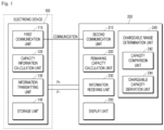
- FIG. 1 is a diagram schematically illustrating a power bank having a chargeable capacity providing function according to the present invention and a battery pack charging system including the same.
- the battery pack charging system of the present invention is configured to include a power bank 200 and a battery pack 100 charged by receiving charging power from the power bank 200.
- the battery pack 100 is a configuration that is charged by receiving charging power from the power bank 200 through a charging terminal (not illustrated and functions as a power driving source for an electronic device (e.g., a mobile phone, a laptop, etc.) in which the battery pack 100 is mounted.
- a charging terminal not illustrated and functions as a power driving source for an electronic device (e.g., a mobile phone, a laptop, etc.) in which the battery pack 100 is mounted.
- the battery pack 100 of the present invention may be configured to include the following detailed configurations.
- the first communication unit 110 is a configuration for mutual data communication with the power bank (200). More specifically, it is communicatively connected to a second communication unit 210 of the power bank 200 to be described later.
- the data communication connection may be made in a wired or wireless connection method.
- the capacity information calculation unit 120 measures an open circuit voltage (OCV, open circuit voltage) value of the battery pack 100, and calculates a measured capacity by using the measured OCV value.
- OCV open circuit voltage
- a known technique is used in calculating the measured capacity according to the OCV measured value.
- the information transmitting unit 130 is a configuration that transmits the measured capacity of the battery pack 100 calculated by the capacity information calculating unit 120, a capacity, and an SOC table stored in a storage unit 140 to be described later to the power bank 200 through the first communication unit 110.
- the storage unit 140 is a configuration that stores a capacity and SOC table in which a capacity for each open circuit voltage (OCV) and a state of charge (SOC, %) corresponding thereto is recorded, prepared in advance through an experiment.
- OCV open circuit voltage
- SOC state of charge
- the capacity and SOC table may be, for example, in the form of the table shown in FIG. 2 .
- the power bank or auxiliary battery 200 is a device for charging a connected electronic device (e.g., the mobile phone, laptop, etc.) (not illustrated) by applying power stored in a battery provided therein to the battery pack 100 built in the connected electronic device.
- a connected electronic device e.g., the mobile phone, laptop, etc.
- the power bank 200 of the present invention is configured to receive capacity information of the battery pack 100 through a communication connection with the battery pack 100, and provide information on a chargeable capacity of the battery pack 100 based on the received capacity information of the battery pack 100 and a remaining capacity of the power bank 200.
- Such a power bank 200 includes a power bank battery, and may be configured to further include the following detailed configuration.
- Second communication unit 210 Second communication unit 210
- the second communication unit 210 is a configuration for mutual data communication with the charging target battery pack 100 to be charged. More specifically, it is communicatively connected to the first communication unit 110 of the battery pack 100 described above.
- the data communication connection may be made in a wired or wireless connection method.
- the remaining capacity calculation unit 220 is a configuration that calculates a remaining capacity of the power bank 200, specifically, the remaining capacity of a power bank battery (not illustrated) built in the power bank 200.
- a known technique is used in calculating the remaining capacity.
- the information receiving unit 230 is a configuration that receives the measured capacity information of the battery pack 100 and the capacity SOC table from the battery pack 100 through the second communication unit 210.
- the chargeable range determination unit is a configuration that compares a sum capacity of the measured capacity of the battery pack 100 received by the information receiving unit 230 and the remaining capacity of the power bank 200 calculated by the remaining capacity calculation unit 220 with a buffer capacity of the battery pack 100 to determine a chargeable range of the battery pack 100 with the power of the power bank 200 according to the comparison result.
- the chargeable range determination unit 240 may be configured to include the following detailed configuration.
- the capacity comparison unit 242 is a configuration that compares the sum capacity of the measured capacity of the battery pack 100 received by the information receiving unit 230 and the remaining capacity of the power bank 200 calculated by the remaining capacity calculation unit 220 with the buffer capacity of the battery pack 100.
- the chargeable capacity derivation unit 244 is a configuration that derives the chargeable capacity of the battery pack 100 with the power of the power bank 200 according to the comparison result of the capacity comparison unit 242.
- the chargeable capacity of the battery pack 100 may be derived as 100%.
- an SOC value corresponding to the sum capacity may be extracted from the capacity and SOC table in which the capacity for each OCV from the battery pack 100 and the SOC (%) is recorded from the battery pack 100, and the extracted SOC value (%) may be derived as the chargeable capacity of the battery pack.
- the sum capacity of the capacity of the battery pack and the capacity of the power bank is 9 Ah.
- 90% which is an SOC value corresponding to 9 Ah, is derived from the capacity and SOC table as shown in the table of FIG. 2 , and this is derived as the chargeable capacity of the battery pack 100.
- the display unit 250 is a configuration that displays the chargeable range of the battery pack 100 determined by the chargeable range determination unit 240 so that the user can check the chargeable range.
- the display unit of the present invention may include a first display unit displaying the remaining capacity of the power bank and a second display unit that numerically displays how much the battery pack 100, that is, a counterpart to be charged, can be charged.
- Such configurations of the power bank 200 may be implemented in a battery management system (BMS) of the power bank 200.
- BMS battery management system
- FIG. 3 is a diagram illustrating a method of charging the battery pack with the power bank having the function of providing a chargeable range of the battery pack according to the present invention.
- the method of the present invention may be configured to include the following steps.
- the communication connection step S100 is a step of connecting data communication between the power bank or the auxiliary battery 200 and the battery pack 100 charged by receiving charging power from the power bank 200.
- the data communication connection may be made in a wired or wireless connection method.
- the capacity and SOC table obtaining step S200 is a step of obtaining, by the power bank 200, a capacity and SOC table in which a capacity for each open circuit voltage (OCV) and SOC (%) are recorded from the battery pack 100 which is communicatively connected in the communication connection step S100.
- the capacity and SOC table may be, for example, in the form of a table as shown in FIG. 2 .
- the measured capacity information receiving step S300 is a step of receiving, by the power bank 200, a measured capacity according to an OCV measurement value of the battery pack 100 from the battery pack which is communicatively connected.
- the open circuit voltage (OCV) value of the battery pack 100 is measured and the measured capacity is calculated using the measured OCV value.
- a known technique is used in calculating the measured capacity according to the OCV measured value.
- the remaining capacity information calculation step S400 is a step of measuring/calculating the remaining capacity of the power bank 200. More specifically, the remaining capacity of the battery (not illustrated) built in the power bank 200 is calculated.
- a known technique is used in calculating the remaining capacity.
- the chargeable range determination step S500 is a step of comparing, by the power bank 200, a sum capacity of the calculated remaining capacity of the power bank 200 and the measured capacity received from the battery pack 100 with a buffer capacity of the battery pack 100 to determine a chargeable range of the battery pack with the power of the power bank 200 according to the comparison result.
- This chargeable range determination step (S500) may be configured to include the following detailed steps.
- the capacity comparison step S510 is a step of comparing the sum of the remaining capacity of the power bank 200 calculated in the remaining capacity information calculation step S400 and the measured capacity of the battery pack 100 received in the measured capacity information receiving step S300 with the buffer capacity of the battery pack 100.
- the chargeable capacity of the battery pack 100 is derived with the power of the power bank 200 according to the comparison result of the capacity comparison step S510.
- the chargeable capacity of the battery pack 100 may be derived as 100%.
- an SOC value corresponding to the sum capacity may be extracted from the capacity and SOC table, in which the capacity for each OCV and the SOC (%) are recorded, obtained from the battery pack 100, and the extracted SOC value (%) may be derived as the chargeable capacity of the battery pack 100.
- the sum capacity of the capacity of the battery pack and the capacity of the power bank is 9 Ah.
- 90% which is an SOC value corresponding to 9 Ah, is derived from the capacity and SOC table as shown in the table of FIG. 2 , and this is derived as the chargeable capacity of the battery pack 100.
- the information display step S600 is a step of displaying the chargeable capacity value (%) derived in the chargeable capacity derivation step S520 of the chargeable range determination step S500 on an external display 250 provided in the power bank 200.
Landscapes
- Engineering & Computer Science (AREA)
- Power Engineering (AREA)
- Physics & Mathematics (AREA)
- General Physics & Mathematics (AREA)
- Charge And Discharge Circuits For Batteries Or The Like (AREA)
- Secondary Cells (AREA)
Abstract
Description
- The present invention relates to a battery pack charging system and a method therefor, and more particularly, to a power bank having a function of providing a chargeable range of a battery pack, and the battery pack charging system including the same, and the method thereof.
- Recently, as the number of people who enjoy camping increases, the demand for a power bank is increasing to use an electronic device in outdoor environments where an electric outlet is not available. In addition, an auxiliary battery is widely used to charge and use various electronic devices including a mobile phone and a notebook computer.
- In order to prevent a sudden unusable situation from occurring due to battery exhaustion of the electronic device in outdoor environments, it is important to predict and use how much the power bank or auxiliary battery can charge the electronic device that a charging counterpart.
- However, in the case of most current power banks and auxiliary batteries, only the remaining capacity information of the power bank or auxiliary battery is provided through an external LED, and information on how far the charging target (electronic device) can be charged with the current power of the power bank or auxiliary battery is not provided. Accordingly, the user is using the power bank and the auxiliary battery depending on empirical rough information (LED) without knowing exact information about chargeable capacity of the charging counterpart and accordingly, a problem accompanied by inconvenience and anxiety occurs in the process of using it.
- As such prior art, there is a following patent document.
- Patent literature 1:
KR 1561069 B1 - The present invention is intended to solve the problems described above, and is to provide information on how far the charging counterpart can be charged through an external display of the power bank (auxiliary battery) based on the remaining capacity of the power bank (auxiliary battery) and the current capacity of the charging counterpart after checking the capacity information through communication between the power bank (auxiliary battery) and the charging counterpart.
- The present invention provides a battery pack charging system configured to include a power bank and a battery pack charged by receiving charging power from the power bank, in which the power bank and the battery pack each include a communication unit for mutual data communication, and a battery management system (BMS) of the power bank receives measured capacity information of the battery pack through a communication connection with the battery pack, and provides information (%) of chargeable capacity of the battery pack based on the received measured capacity information of the battery pack and a remaining capacity of the power bank.
- In this case, the battery pack may be configured to include a first communication unit connected to the power bank through wired/wireless communication, a capacity information calculation unit that measures a value of open circuit voltage (OCV) of the battery pack and calculates a measured capacity using the measured value of OCV, an information transmitting unit that transmits the measured capacity of the battery pack calculated by the capacity information calculation unit and a capacity and SOC table of a storage unit to the power bank through the first communication unit, and the storage unit that stores the capacity and SOC table in which a capacity for each OCV and a state of charge (SOC, %) is recorded.
- In addition, the power bank may be configured to include a second communication unit connected to the battery pack through wired/wireless communication, a remaining capacity calculation unit that calculates the remaining capacity of the power bank, an information receiving unit that receives the measured capacity information of the battery pack and the capacity and SOC table from the battery pack through the second communication unit, a chargeable range determination unit that compares a sum capacity of the measured capacity of the battery pack received by the information receiving unit and the remaining capacity of the power bank calculated by the remaining capacity calculation unit with a buffer capacity of the battery pack to determine a chargeable range of the battery pack according to the comparison result, and a display unit that externally displays the chargeable range of the battery pack determined by the chargeable range determination unit.
- In this case, the chargeable range determination unit may be configured to include a capacity comparison unit that compares the sum capacity of the measured capacity of the battery pack received by the information receiving unit and the remaining capacity of the power bank calculated by the remaining capacity calculation unit with the buffer capacity the battery pack, and a chargeable capacity derivation unit that derives a chargeable capacity (%) of the battery pack with power of the power bank according to the comparison result of the capacity comparison unit.
- The chargeable capacity derivation unit derives the chargeable capacity of the battery pack as 100% when the sum capacity is equal to or greater than the buffer capacity of the battery pack as a result of the comparison of the capacity comparison unit, and extracts an SOC value corresponding to the sum capacity from the capacity and SOC table obtained from the battery pack to derive the extracted SOC value (%) as the chargeable capacity of the battery pack when the sum capacity is less than the buffer capacity of the battery pack as a result of the comparison of the capacity comparison unit.
- In addition, the present invention provides a method for charging a battery pack configured to include a communication connection step of connecting mutual data communication between a power bank and a battery pack charged by receiving charging power from the power bank, a capacity and SOC table obtaining step of obtaining, by the power bank, a capacity and SOC table in which a capacity for each open circuit voltage (OCV) and a SOC (%) are recorded from the battery pack which is communicatively connected in the communication connection step, a measured capacity information receiving step of receiving, by the power bank, a measured capacity according to an OCV measured value of the battery pack from the battery pack which is communicatively connected in the communication connection step, a remaining capacity information calculation step of calculating, by the power bank, a remaining capacity of the power bank, a chargeable range determination step of comparing, by the power bank, a sum capacity of the calculated remaining capacity of the power bank and the measured capacity of the battery pack received from the battery pack with a buffer capacity of the battery pack to determine a chargeable range of the battery pack according to the comparison result, and an information display step of displaying, by the power bank, the determined chargeable range (%) of the battery pack on an external display.
- In this case, the chargeable range determination step may be configured to include a capacity comparison step of comparing the sum capacity of the remaining capacity of the power bank calculated in the remaining capacity information calculation step and the measured capacity of the battery pack received in the measured capacity information receiving step with the buffer capacity of the battery pack, and a chargeable capacity derivation step of deriving the chargeable capacity of the battery pack according to the comparison result in the capacity comparison step.
- In this case, in the chargeable capacity derivation step, when the sum capacity of the remaining capacity of the power bank and the measured capacity of the battery pack is equal to or greater than the buffer capacity of the battery pack as the result of the comparison in the capacity comparison step, the chargeable capacity of the battery pack is derived as 100%, and when the sum capacity of the remaining capacity of the power bank and the measured capacity of the battery pack is less than the buffer capacity of the battery pack as the result of the comparison of the capacity comparison step, an SOC value corresponding to the sum capacity is extracted from the capacity and SOC table, in which a capacity for each OCV and an SOC (%) are recorded, obtained from the battery pack and the extracted SOC value (%) is derived as the chargeable capacity of the battery pack.
- The present invention can improve user convenience by providing information on the chargeable capacity of the charging target (battery pack) to the external display of the power bank (auxiliary battery) based on the remaining capacity of the power bank after checking the capacity information through communication between the power bank and the charging target.
-
-
FIG. 1 is a diagram illustrating a battery pack charging system including a power bank according to the present invention. -
FIG. 2 is a diagram illustrating an example of a capacity and SOC table according to the present invention. -
FIG. 3 is a diagram illustrating a method for charging a battery pack with the power bank according to the present invention. - Hereinafter, embodiments of the present invention will be described in detail with reference to the accompanying drawings so that those of ordinary skill in the art can easily carry out the present invention. However, the present invention may be embodied in various different forms and is not limited to the embodiments described herein. In order to clearly explain the present invention in the drawings, parts irrelevant to the description are omitted, and similar reference numerals are assigned to similar parts throughout the specification.
- Hereinafter, the present invention will be described in detail with reference to the drawings.
-
FIG. 1 is a diagram schematically illustrating a power bank having a chargeable capacity providing function according to the present invention and a battery pack charging system including the same. - Referring to
FIG. 1 , the battery pack charging system of the present invention is configured to include apower bank 200 and abattery pack 100 charged by receiving charging power from thepower bank 200. - The
battery pack 100 is a configuration that is charged by receiving charging power from thepower bank 200 through a charging terminal (not illustrated and functions as a power driving source for an electronic device (e.g., a mobile phone, a laptop, etc.) in which thebattery pack 100 is mounted. - The
battery pack 100 of the present invention may be configured to include the following detailed configurations. - The
first communication unit 110 is a configuration for mutual data communication with the power bank (200). More specifically, it is communicatively connected to asecond communication unit 210 of thepower bank 200 to be described later. The data communication connection may be made in a wired or wireless connection method. - The capacity
information calculation unit 120 measures an open circuit voltage (OCV, open circuit voltage) value of thebattery pack 100, and calculates a measured capacity by using the measured OCV value. - A known technique is used in calculating the measured capacity according to the OCV measured value.
- The
information transmitting unit 130 is a configuration that transmits the measured capacity of thebattery pack 100 calculated by the capacityinformation calculating unit 120, a capacity, and an SOC table stored in astorage unit 140 to be described later to thepower bank 200 through thefirst communication unit 110. - The
storage unit 140 is a configuration that stores a capacity and SOC table in which a capacity for each open circuit voltage (OCV) and a state of charge (SOC, %) corresponding thereto is recorded, prepared in advance through an experiment. - The capacity and SOC table may be, for example, in the form of the table shown in
FIG. 2 . - The power bank or
auxiliary battery 200 is a device for charging a connected electronic device (e.g., the mobile phone, laptop, etc.) (not illustrated) by applying power stored in a battery provided therein to thebattery pack 100 built in the connected electronic device. - The
power bank 200 of the present invention is configured to receive capacity information of thebattery pack 100 through a communication connection with thebattery pack 100, and provide information on a chargeable capacity of thebattery pack 100 based on the received capacity information of thebattery pack 100 and a remaining capacity of thepower bank 200. - Such a
power bank 200 includes a power bank battery, and may be configured to further include the following detailed configuration. - The
second communication unit 210 is a configuration for mutual data communication with the chargingtarget battery pack 100 to be charged. More specifically, it is communicatively connected to thefirst communication unit 110 of thebattery pack 100 described above. The data communication connection may be made in a wired or wireless connection method. - The remaining
capacity calculation unit 220 is a configuration that calculates a remaining capacity of thepower bank 200, specifically, the remaining capacity of a power bank battery (not illustrated) built in thepower bank 200. - A known technique is used in calculating the remaining capacity.
- The
information receiving unit 230 is a configuration that receives the measured capacity information of thebattery pack 100 and the capacity SOC table from thebattery pack 100 through thesecond communication unit 210. - The chargeable range determination unit is a configuration that compares a sum capacity of the measured capacity of the
battery pack 100 received by theinformation receiving unit 230 and the remaining capacity of thepower bank 200 calculated by the remainingcapacity calculation unit 220 with a buffer capacity of thebattery pack 100 to determine a chargeable range of thebattery pack 100 with the power of thepower bank 200 according to the comparison result. - The chargeable
range determination unit 240 may be configured to include the following detailed configuration. - The
capacity comparison unit 242 is a configuration that compares the sum capacity of the measured capacity of thebattery pack 100 received by theinformation receiving unit 230 and the remaining capacity of thepower bank 200 calculated by the remainingcapacity calculation unit 220 with the buffer capacity of thebattery pack 100. - The chargeable
capacity derivation unit 244 is a configuration that derives the chargeable capacity of thebattery pack 100 with the power of thepower bank 200 according to the comparison result of thecapacity comparison unit 242. - Specifically, as a result of the comparison, when the sum capacity is equal to or greater than the buffer capacity of the
battery pack 100, the chargeable capacity of thebattery pack 100 may be derived as 100%. - On the other hand, as a result of the comparison, when the sum capacity is less than the buffer capacity of the
battery pack 100, an SOC value corresponding to the sum capacity may be extracted from the capacity and SOC table in which the capacity for each OCV from thebattery pack 100 and the SOC (%) is recorded from thebattery pack 100, and the extracted SOC value (%) may be derived as the chargeable capacity of the battery pack. - For example, when described with reference to the table of
FIG. 2 , if the measured capacity of thebattery pack 100 is 6 Ah and that of thepower bank 200 is 3 Ah, the sum capacity of the capacity of the battery pack and the capacity of the power bank is 9 Ah. In this case, since the sum capacity is less than thebuffer capacity 10 Ah of the battery pack, 90%, which is an SOC value corresponding to 9 Ah, is derived from the capacity and SOC table as shown in the table ofFIG. 2 , and this is derived as the chargeable capacity of thebattery pack 100. - The
display unit 250 is a configuration that displays the chargeable range of thebattery pack 100 determined by the chargeablerange determination unit 240 so that the user can check the chargeable range. - More specifically, when the chargeable capacity derived from the chargeable
capacity derivation unit 244 of the chargeablerange determination unit 240 is 90%, the display unit displays it externally. The display unit of the present invention may include a first display unit displaying the remaining capacity of the power bank and a second display unit that numerically displays how much thebattery pack 100, that is, a counterpart to be charged, can be charged. - Such configurations of the
power bank 200 may be implemented in a battery management system (BMS) of thepower bank 200. -
FIG. 3 is a diagram illustrating a method of charging the battery pack with the power bank having the function of providing a chargeable range of the battery pack according to the present invention. - Referring to
FIG. 3 , the method of the present invention may be configured to include the following steps. - The communication connection step S100 is a step of connecting data communication between the power bank or the
auxiliary battery 200 and thebattery pack 100 charged by receiving charging power from thepower bank 200. - The data communication connection may be made in a wired or wireless connection method.
- The capacity and SOC table obtaining step S200 is a step of obtaining, by the
power bank 200, a capacity and SOC table in which a capacity for each open circuit voltage (OCV) and SOC (%) are recorded from thebattery pack 100 which is communicatively connected in the communication connection step S100. - Here, the capacity and SOC table may be, for example, in the form of a table as shown in
FIG. 2 . - The measured capacity information receiving step S300 is a step of receiving, by the
power bank 200, a measured capacity according to an OCV measurement value of thebattery pack 100 from the battery pack which is communicatively connected. - Here, in calculating the measured capacity by the
battery pack 100, the open circuit voltage (OCV) value of thebattery pack 100 is measured and the measured capacity is calculated using the measured OCV value. - A known technique is used in calculating the measured capacity according to the OCV measured value.
- The remaining capacity information calculation step S400 is a step of measuring/calculating the remaining capacity of the
power bank 200. More specifically, the remaining capacity of the battery (not illustrated) built in thepower bank 200 is calculated. - A known technique is used in calculating the remaining capacity.
- The chargeable range determination step S500 is a step of comparing, by the
power bank 200, a sum capacity of the calculated remaining capacity of thepower bank 200 and the measured capacity received from thebattery pack 100 with a buffer capacity of thebattery pack 100 to determine a chargeable range of the battery pack with the power of thepower bank 200 according to the comparison result. - This chargeable range determination step (S500) may be configured to include the following detailed steps.
- The capacity comparison step S510 is a step of comparing the sum of the remaining capacity of the
power bank 200 calculated in the remaining capacity information calculation step S400 and the measured capacity of thebattery pack 100 received in the measured capacity information receiving step S300 with the buffer capacity of thebattery pack 100. - In the chargeable capacity derivation step S520, the chargeable capacity of the
battery pack 100 is derived with the power of thepower bank 200 according to the comparison result of the capacity comparison step S510. - Specifically, when the sum of the remaining capacity of the
power bank 200 and the measured capacity of thebattery pack 100 is equal to or greater than the buffer capacity of the battery pack as the result of the comparison in the capacity comparison step S510, the chargeable capacity of thebattery pack 100 may be derived as 100%. - On the other hand, when the sum capacity of the remaining capacity of the
power bank 200 and the measured capacity of thebattery pack 100 is less than the buffer capacity of the battery pack as the result of the comparison of the capacity comparison step S510, an SOC value corresponding to the sum capacity may be extracted from the capacity and SOC table, in which the capacity for each OCV and the SOC (%) are recorded, obtained from thebattery pack 100, and the extracted SOC value (%) may be derived as the chargeable capacity of thebattery pack 100. - For example, when described with reference to the table of
FIG. 2 , if the measured capacity of thebattery pack 100 is 6 Ah and that of thepower bank 200 is 3 Ah, the sum capacity of the capacity of the battery pack and the capacity of the power bank is 9 Ah. In this case, since the sum capacity is less than thebuffer capacity 10 Ah of the battery pack, 90%, which is an SOC value corresponding to 9 Ah, is derived from the capacity and SOC table as shown in the table ofFIG. 2 , and this is derived as the chargeable capacity of thebattery pack 100. - The information display step S600 is a step of displaying the chargeable capacity value (%) derived in the chargeable capacity derivation step S520 of the chargeable range determination step S500 on an
external display 250 provided in thepower bank 200. - In this way, information on how far the battery pack can be charged based the remaining capacity of the power bank and the measured capacity of the battery pack through communication between the power bank (auxiliary battery) and the battery pack built into the charging counterpart (electronic device) is displayed and provided to the user, thereby capable of increasing convenience and satisfaction with use of the user.
- Meanwhile, although the technical idea of the present invention has been described in detail according to the above embodiments, it should be noted that the above embodiments are for description and not for limitation. In addition, those skilled in the art will understand that various embodiments are possible within the scope of the technical spirit of the present invention.
- Although the power bank having a function of providing a chargeable range of a battery pack, the battery pack charging system including the same, and the method therefor have been described with reference to the specific embodiments, they are not limited thereto. Therefore, it will be readily understood by those skilled in the art that various modifications and changes can be made thereto without departing from the spirit and scope of the present invention defined by the appended claims.
Claims (14)
- A battery pack charging system configured to comprise a power bank and a battery pack for charging by receiving charging power from the power bank, whereinthe power bank and the battery pack each comprise a communication unit for mutual data communication, anda battery management system (BMS) of the power bank receives measured capacity information of the battery pack through a communication connection with the battery pack, and provides information (%) of chargeable capacity of the battery pack based on the received measured capacity information of the battery pack and a remaining capacity of the power bank.
- The battery pack charging system of claim 1, wherein
the battery pack is configured to comprisea first communication unit connected to the power bank through wired/wireless communication,a capacity information calculation unit that measures a value of open circuit voltage (OCV) of the battery pack and calculates a measured capacity using the measured value of OCV,an information transmitting unit that transmits the measured capacity of the battery pack calculated by the capacity information calculation unit and a capacity and SOC table of a storage unit to the power bank through the first communication unit, andthe storage unit that stores the capacity and SOC table in which a capacity for each OCV and a state of charge (SOC, %) are recorded. - The battery pack charging system of claim 1, wherein
the power bank is configured to comprisea second communication unit connected to the battery pack through wired/wireless communication,a remaining capacity calculation unit that calculates the remaining capacity of the power bank,an information receiving unit that receives the measured capacity information of the battery pack and the capacity and SOC table from the battery pack through the second communication unit,a chargeable range determination unit that compares a sum capacity of the measured capacity of the battery pack received by the information receiving unit and the remaining capacity of the power bank calculated by the remaining capacity calculation unit with a buffer capacity of the battery pack to determine a chargeable range of the battery pack according to the comparison result, anda display unit that externally displays the chargeable range of the battery pack determined by the chargeable range determination unit. - The battery pack charging system of claim 3, wherein
the chargeable range determination unit is configured to comprisea capacity comparison unit that compares the sum capacity of the measured capacity of the battery pack received by the information receiving unit and the remaining capacity of the power bank calculated by the remaining capacity calculation unit with the buffer capacity the battery pack, anda chargeable capacity derivation unit that derives a chargeable capacity (%) of the battery pack with power of the power bank according to the comparison result of the capacity comparison unit. - The battery pack charging system of claim 4, wherein
the chargeable capacity derivation unit derives the chargeable capacity of the battery pack as 100% when the sum capacity is equal to or greater than the buffer capacity of the battery pack as a result of the comparison of the capacity comparison unit. - The battery pack charging system of claim 4, wherein
the chargeable capacity derivation unit extracts an SOC value corresponding to the sum capacity from the capacity and SOC table obtained from the battery pack to derive the extracted SOC value (%) as the chargeable capacity of the battery pack, when the sum capacity is less than the buffer capacity of the battery pack as a result of the comparison of the capacity comparison unit. - A method for charging a battery pack comprising:a communication connection step of connecting mutual data communication between a power bank and a battery pack charged by receiving charging power from the power bank;a capacity and SOC table obtaining step of obtaining, by the power bank, a capacity and SOC table, in which a capacity for each open circuit voltage (OCV) and a SOC (%) are recorded, from the battery pack which is communicatively connected in the communication connection step;a measured capacity information receiving step of receiving, by the power bank, a measured capacity according to an OCV measured value of the battery pack from the battery pack which is communicatively connected in the communication connection step;a remaining capacity information calculation step of calculating, by the power bank, a remaining capacity of the power bank;a chargeable range determination step of comparing, by the power bank, a sum capacity of the calculated remaining capacity of the power bank and the measured capacity of the battery pack received from the battery pack with a buffer capacity of the battery pack to determine a chargeable range of the battery pack according to the comparison result; andan information display step of displaying, by the power bank, the determined chargeable range (%) of the battery pack on an external display.
- The method of claim 7, wherein
the chargeable range determination step is configured to comprisea capacity comparison step of comparing a sum capacity of the remaining capacity of the power bank calculated in the remaining capacity information calculation step and the measured capacity of the battery pack received in the measured capacity information receiving step with the buffer capacity of the battery pack, anda chargeable capacity derivation step of deriving the chargeable capacity of the battery pack according to the comparison result in the capacity comparison step. - The method of claim 8, whereinin the chargeable capacity derivation step,when the sum capacity of the remaining capacity of the power bank and the measured capacity of the battery pack is equal to or greater than the buffer capacity of the battery pack as the result of the comparison in the capacity comparison step, the chargeable capacity of the battery pack is derived as 100%.
- The method of claim 8, whereinin the chargeable capacity derivation step,when the sum capacity of the remaining capacity of the power bank and the measured capacity of the battery pack is less than the buffer capacity of the battery pack as the result of the comparison of the capacity comparison step, an SOC value corresponding to the sum capacity is extracted from the capacity and SOC table, in which the capacity for each OCV and the SOC (%) are recorded, obtained from the battery pack and the extracted SOC value (%) is derived as the chargeable capacity of the battery pack.
- A power bank comprising:a power bank battery;a communication unit connected to a charging target battery pack to be charged through wired/wireless communication;a remaining capacity calculation unit that calculates a remaining capacity of the power bank battery;an information receiving unit that receives measured capacity information of the charging target battery pack and a capacity and SOC table from the charging target battery pack through the communication unit;a chargeable range determination unit that compares a sum capacity of the measured capacity of the charging target battery pack received by the information receiving unit and the remaining capacity of the power bank calculated by the remaining capacity calculation unit with a buffer capacity of the charging target battery pack to determine a chargeable range of the charging target battery pack according to the comparison result; anda display unit that externally displays the chargeable range of the charging target battery pack determined by the chargeable range determination unit.
- The power bank of claim 11, wherein
the chargeable range determination unit is configured to comprisea capacity comparison unit that compares the sum capacity of the measured capacity of the charging target battery pack received by the information receiving unit and the remaining capacity of the power bank calculated by the remaining capacity calculation unit with the buffer capacity of the charging target battery pack, anda chargeable capacity derivation unit that derives a chargeable capacity (%) of the charging target battery pack with power of the power bank according to the comparison result of the capacity comparison unit. - The power bank of claim 12, wherein
the chargeable capacity derivation unitderives the chargeable capacity of the charging target battery pack as 100% when the sum capacity is equal to or greater than the buffer capacity of the charging target battery pack as a result of the comparison of the capacity comparison unit, andextracts an SOC value corresponding to the sum capacity from the capacity and SOC table obtained from the charging target battery pack to derive the extracted SOC value (%) as the chargeable capacity of the charging target battery pack, when the sum capacity is less than the buffer capacity of the charging target battery pack as a result of the comparison of the capacity comparison unit. - The power bank of claim 13, wherein
the display unit displays a number of the extracted SOC value (%).
Applications Claiming Priority (2)
| Application Number | Priority Date | Filing Date | Title |
|---|---|---|---|
| KR1020210145885A KR20230061043A (en) | 2021-10-28 | 2021-10-28 | A power bank having a function of providing a chargeable range of a battery pack, a battery pack charging system including the same, and a method therefor |
| PCT/KR2022/016501 WO2023075427A1 (en) | 2021-10-28 | 2022-10-26 | Power bank having function for providing rechargeable range of battery pack, battery pack charging system comprising same, and method therefor |
Publications (3)
| Publication Number | Publication Date |
|---|---|
| EP4243241A1 true EP4243241A1 (en) | 2023-09-13 |
| EP4243241A4 EP4243241A4 (en) | 2024-07-10 |
| EP4243241B1 EP4243241B1 (en) | 2025-08-06 |
Family
ID=86158223
Family Applications (1)
| Application Number | Title | Priority Date | Filing Date |
|---|---|---|---|
| EP22887623.1A Active EP4243241B1 (en) | 2021-10-28 | 2022-10-26 | Power bank having function for providing rechargeable range of battery pack, battery pack charging system comprising same, and method therefor |
Country Status (8)
| Country | Link |
|---|---|
| US (1) | US20240085482A1 (en) |
| EP (1) | EP4243241B1 (en) |
| JP (1) | JP7592870B2 (en) |
| KR (1) | KR20230061043A (en) |
| CN (1) | CN116636109A (en) |
| ES (1) | ES3039107T3 (en) |
| HU (1) | HUE072608T2 (en) |
| WO (1) | WO2023075427A1 (en) |
Family Cites Families (17)
| Publication number | Priority date | Publication date | Assignee | Title |
|---|---|---|---|---|
| KR101219920B1 (en) * | 2006-06-08 | 2013-01-18 | 엘지전자 주식회사 | Appratus and Method of Battery management in the portable terminal |
| JP4650567B2 (en) * | 2008-12-24 | 2011-03-16 | 三菱自動車工業株式会社 | Electric vehicle charging display |
| JP5834680B2 (en) * | 2011-09-20 | 2015-12-24 | トヨタ自動車株式会社 | Control device for display device |
| KR101311592B1 (en) * | 2012-02-15 | 2013-09-26 | 세종공업 주식회사 | Display unit for fuel cell system, and fuel cell system including the same |
| KR101644217B1 (en) * | 2013-07-02 | 2016-07-29 | 주식회사 엘지화학 | Apparatus and method for battery protection |
| GB2524973A (en) * | 2014-04-07 | 2015-10-14 | Intelligent Energy Ltd | Power supply apparatus |
| KR20150142216A (en) * | 2014-06-11 | 2015-12-22 | 주식회사 켐트로닉스 | Auxiliary battery having solar collector with transmitter-receiver wireless charge |
| KR101648626B1 (en) * | 2014-08-19 | 2016-08-16 | 경북대학교 산학협력단 | Device, system and method for wireless power relay, recording medium for performing the method |
| KR101501031B1 (en) * | 2014-08-22 | 2015-03-12 | (주)한국전자기술 | A portable charging apparatus and a charging control method thereof |
| KR101561069B1 (en) | 2015-02-09 | 2015-10-22 | 주식회사 에이블유 | Charging cradle with spare battery function |
| KR101792818B1 (en) * | 2015-03-26 | 2017-11-01 | 주식회사 엘지화학 | Energy storage system |
| CN106786961B (en) * | 2017-01-13 | 2019-05-24 | Oppo广东移动通信有限公司 | Charging processing method, device and terminal |
| JP6787220B2 (en) * | 2017-03-29 | 2020-11-18 | Tdk株式会社 | Power storage system |
| JPWO2019240245A1 (en) | 2018-06-14 | 2021-07-15 | 本田技研工業株式会社 | Display device and display method |
| KR102645147B1 (en) * | 2018-10-31 | 2024-03-08 | 삼성전자주식회사 | Electronic device charging battery of multiple parts |
| US11233412B2 (en) * | 2020-03-23 | 2022-01-25 | Duracell U.S. Operations, Inc. | Intelligent determination of charges remaining via a power bank |
| JP7414624B2 (en) | 2020-04-10 | 2024-01-16 | キヤノン株式会社 | Electronic equipment, control methods and computer readable storage media |
-
2021
- 2021-10-28 KR KR1020210145885A patent/KR20230061043A/en active Pending
-
2022
- 2022-10-26 JP JP2023535776A patent/JP7592870B2/en active Active
- 2022-10-26 EP EP22887623.1A patent/EP4243241B1/en active Active
- 2022-10-26 US US18/270,161 patent/US20240085482A1/en active Pending
- 2022-10-26 CN CN202280008158.6A patent/CN116636109A/en active Pending
- 2022-10-26 ES ES22887623T patent/ES3039107T3/en active Active
- 2022-10-26 WO PCT/KR2022/016501 patent/WO2023075427A1/en not_active Ceased
- 2022-10-26 HU HUE22887623A patent/HUE072608T2/en unknown
Also Published As
| Publication number | Publication date |
|---|---|
| KR20230061043A (en) | 2023-05-08 |
| CN116636109A (en) | 2023-08-22 |
| JP7592870B2 (en) | 2024-12-02 |
| EP4243241B1 (en) | 2025-08-06 |
| JP2023553636A (en) | 2023-12-25 |
| EP4243241A4 (en) | 2024-07-10 |
| ES3039107T3 (en) | 2025-10-17 |
| US20240085482A1 (en) | 2024-03-14 |
| HUE072608T2 (en) | 2025-11-28 |
| WO2023075427A1 (en) | 2023-05-04 |
Similar Documents
| Publication | Publication Date | Title |
|---|---|---|
| US7098666B2 (en) | Method and system for battery state of charge estimation by using measured changes in voltage | |
| CN106324508B (en) | Battery health state detection device and method | |
| US6472847B2 (en) | Battery operable device with battery state-of-charge indicator | |
| JP4123184B2 (en) | Secondary battery remaining capacity calculation method and battery pack | |
| US9385552B2 (en) | Method of detecting charger type and estimating remaining recharging time for mobile devices with USB recharging | |
| Pop et al. | State-of-the-art of battery state-of-charge determination | |
| US8319479B2 (en) | Method of estimating battery recharge time and related device | |
| CN101430366B (en) | Battery charge state detection method | |
| US7671566B2 (en) | Method for predicting remaining capacity of a battery | |
| JP6755126B2 (en) | Deterioration judgment device for secondary batteries | |
| WO2017152823A1 (en) | Apparatus and method for detecting state of health of battery | |
| US20120101754A1 (en) | Method of estimating remaining constant current/constant voltage charging time | |
| KR101488828B1 (en) | Apparatus for measuring a life time of secondary battery, electronic equipment comprising it and method for measuring a life time of secondary battery | |
| US20190004115A1 (en) | Battery state estimation device, battery control device, battery system, battery state estimation method | |
| CN102066964A (en) | Systems and methods for determining battery state of charge | |
| CN104112878A (en) | Method and device for determining charging time and electronic device | |
| CN102854471A (en) | Method and device for metering electric quantity of battery | |
| KR20190049272A (en) | Apparatus and method for estimating SOC of battery | |
| JP2018068081A (en) | Secondary battery charging time prediction device and method | |
| JP2013526251A (en) | Built-in charger | |
| JP2025542291A (en) | Battery gas generation amount prediction device and operation method | |
| EP4243241A1 (en) | Power bank having function for providing rechargeable range of battery pack, battery pack charging system comprising same, and method therefor | |
| TW202107108A (en) | Residual power estimation method | |
| EP1199767B1 (en) | Battery operable device with battery state-of-charge indicator | |
| KR20230022667A (en) | Battery Management Method and Battery Management System |
Legal Events
| Date | Code | Title | Description |
|---|---|---|---|
| STAA | Information on the status of an ep patent application or granted ep patent |
Free format text: STATUS: THE INTERNATIONAL PUBLICATION HAS BEEN MADE |
|
| PUAI | Public reference made under article 153(3) epc to a published international application that has entered the european phase |
Free format text: ORIGINAL CODE: 0009012 |
|
| STAA | Information on the status of an ep patent application or granted ep patent |
Free format text: STATUS: REQUEST FOR EXAMINATION WAS MADE |
|
| 17P | Request for examination filed |
Effective date: 20230609 |
|
| AK | Designated contracting states |
Kind code of ref document: A1 Designated state(s): AL AT BE BG CH CY CZ DE DK EE ES FI FR GB GR HR HU IE IS IT LI LT LU LV MC ME MK MT NL NO PL PT RO RS SE SI SK SM TR |
|
| A4 | Supplementary search report drawn up and despatched |
Effective date: 20240606 |
|
| RIC1 | Information provided on ipc code assigned before grant |
Ipc: G01R 31/371 20190101ALI20240531BHEP Ipc: H02J 7/00 20060101ALI20240531BHEP Ipc: H02J 7/34 20060101AFI20240531BHEP |
|
| DAV | Request for validation of the european patent (deleted) | ||
| DAX | Request for extension of the european patent (deleted) | ||
| GRAP | Despatch of communication of intention to grant a patent |
Free format text: ORIGINAL CODE: EPIDOSNIGR1 |
|
| STAA | Information on the status of an ep patent application or granted ep patent |
Free format text: STATUS: GRANT OF PATENT IS INTENDED |
|
| INTG | Intention to grant announced |
Effective date: 20250312 |
|
| P01 | Opt-out of the competence of the unified patent court (upc) registered |
Free format text: CASE NUMBER: APP_16866/2025 Effective date: 20250407 |
|
| GRAS | Grant fee paid |
Free format text: ORIGINAL CODE: EPIDOSNIGR3 |
|
| GRAA | (expected) grant |
Free format text: ORIGINAL CODE: 0009210 |
|
| STAA | Information on the status of an ep patent application or granted ep patent |
Free format text: STATUS: THE PATENT HAS BEEN GRANTED |
|
| AK | Designated contracting states |
Kind code of ref document: B1 Designated state(s): AL AT BE BG CH CY CZ DE DK EE ES FI FR GB GR HR HU IE IS IT LI LT LU LV MC ME MK MT NL NO PL PT RO RS SE SI SK SM TR |
|
| REG | Reference to a national code |
Ref country code: GB Ref legal event code: FG4D |
|
| REG | Reference to a national code |
Ref country code: CH Ref legal event code: EP |
|
| REG | Reference to a national code |
Ref country code: DE Ref legal event code: R096 Ref document number: 602022019169 Country of ref document: DE |
|
| REG | Reference to a national code |
Ref country code: IE Ref legal event code: FG4D |
|
| REG | Reference to a national code |
Ref country code: ES Ref legal event code: FG2A Ref document number: 3039107 Country of ref document: ES Kind code of ref document: T3 Effective date: 20251017 |
|
| REG | Reference to a national code |
Ref country code: HU Ref legal event code: AG4A Ref document number: E072608 Country of ref document: HU |
|
| REG | Reference to a national code |
Ref country code: NL Ref legal event code: MP Effective date: 20250806 |
|
| PGFP | Annual fee paid to national office [announced via postgrant information from national office to epo] |
Ref country code: HU Payment date: 20251127 Year of fee payment: 4 |
|
| PG25 | Lapsed in a contracting state [announced via postgrant information from national office to epo] |
Ref country code: IS Free format text: LAPSE BECAUSE OF FAILURE TO SUBMIT A TRANSLATION OF THE DESCRIPTION OR TO PAY THE FEE WITHIN THE PRESCRIBED TIME-LIMIT Effective date: 20251206 |
|
| PGFP | Annual fee paid to national office [announced via postgrant information from national office to epo] |
Ref country code: DE Payment date: 20251105 Year of fee payment: 4 |
|
| PG25 | Lapsed in a contracting state [announced via postgrant information from national office to epo] |
Ref country code: NO Free format text: LAPSE BECAUSE OF FAILURE TO SUBMIT A TRANSLATION OF THE DESCRIPTION OR TO PAY THE FEE WITHIN THE PRESCRIBED TIME-LIMIT Effective date: 20251106 |
|
| REG | Reference to a national code |
Ref country code: LT Ref legal event code: MG9D |
|
| PG25 | Lapsed in a contracting state [announced via postgrant information from national office to epo] |
Ref country code: PT Free format text: LAPSE BECAUSE OF FAILURE TO SUBMIT A TRANSLATION OF THE DESCRIPTION OR TO PAY THE FEE WITHIN THE PRESCRIBED TIME-LIMIT Effective date: 20251209 |
|
| PG25 | Lapsed in a contracting state [announced via postgrant information from national office to epo] |
Ref country code: FI Free format text: LAPSE BECAUSE OF FAILURE TO SUBMIT A TRANSLATION OF THE DESCRIPTION OR TO PAY THE FEE WITHIN THE PRESCRIBED TIME-LIMIT Effective date: 20250806 |
|
| PG25 | Lapsed in a contracting state [announced via postgrant information from national office to epo] |
Ref country code: HR Free format text: LAPSE BECAUSE OF FAILURE TO SUBMIT A TRANSLATION OF THE DESCRIPTION OR TO PAY THE FEE WITHIN THE PRESCRIBED TIME-LIMIT Effective date: 20250806 Ref country code: NL Free format text: LAPSE BECAUSE OF FAILURE TO SUBMIT A TRANSLATION OF THE DESCRIPTION OR TO PAY THE FEE WITHIN THE PRESCRIBED TIME-LIMIT Effective date: 20250806 |
|
| PGFP | Annual fee paid to national office [announced via postgrant information from national office to epo] |
Ref country code: FR Payment date: 20251031 Year of fee payment: 4 |
|
| PG25 | Lapsed in a contracting state [announced via postgrant information from national office to epo] |
Ref country code: GR Free format text: LAPSE BECAUSE OF FAILURE TO SUBMIT A TRANSLATION OF THE DESCRIPTION OR TO PAY THE FEE WITHIN THE PRESCRIBED TIME-LIMIT Effective date: 20251107 |
|
| PGFP | Annual fee paid to national office [announced via postgrant information from national office to epo] |
Ref country code: BE Payment date: 20251028 Year of fee payment: 4 |
|
| PG25 | Lapsed in a contracting state [announced via postgrant information from national office to epo] |
Ref country code: SE Free format text: LAPSE BECAUSE OF FAILURE TO SUBMIT A TRANSLATION OF THE DESCRIPTION OR TO PAY THE FEE WITHIN THE PRESCRIBED TIME-LIMIT Effective date: 20250806 |
|
| PG25 | Lapsed in a contracting state [announced via postgrant information from national office to epo] |
Ref country code: LV Free format text: LAPSE BECAUSE OF FAILURE TO SUBMIT A TRANSLATION OF THE DESCRIPTION OR TO PAY THE FEE WITHIN THE PRESCRIBED TIME-LIMIT Effective date: 20250806 |
|
| PG25 | Lapsed in a contracting state [announced via postgrant information from national office to epo] |
Ref country code: BG Free format text: LAPSE BECAUSE OF FAILURE TO SUBMIT A TRANSLATION OF THE DESCRIPTION OR TO PAY THE FEE WITHIN THE PRESCRIBED TIME-LIMIT Effective date: 20250806 Ref country code: PL Free format text: LAPSE BECAUSE OF FAILURE TO SUBMIT A TRANSLATION OF THE DESCRIPTION OR TO PAY THE FEE WITHIN THE PRESCRIBED TIME-LIMIT Effective date: 20250806 |
|
| PG25 | Lapsed in a contracting state [announced via postgrant information from national office to epo] |
Ref country code: RS Free format text: LAPSE BECAUSE OF FAILURE TO SUBMIT A TRANSLATION OF THE DESCRIPTION OR TO PAY THE FEE WITHIN THE PRESCRIBED TIME-LIMIT Effective date: 20251106 |
|
| PGFP | Annual fee paid to national office [announced via postgrant information from national office to epo] |
Ref country code: ES Payment date: 20251117 Year of fee payment: 4 |
|
| REG | Reference to a national code |
Ref country code: AT Ref legal event code: MK05 Ref document number: 1823106 Country of ref document: AT Kind code of ref document: T Effective date: 20250806 |
|
| PG25 | Lapsed in a contracting state [announced via postgrant information from national office to epo] |
Ref country code: RO Free format text: LAPSE BECAUSE OF FAILURE TO SUBMIT A TRANSLATION OF THE DESCRIPTION OR TO PAY THE FEE WITHIN THE PRESCRIBED TIME-LIMIT Effective date: 20250806 |
|
| PG25 | Lapsed in a contracting state [announced via postgrant information from national office to epo] |
Ref country code: SM Free format text: LAPSE BECAUSE OF FAILURE TO SUBMIT A TRANSLATION OF THE DESCRIPTION OR TO PAY THE FEE WITHIN THE PRESCRIBED TIME-LIMIT Effective date: 20250806 |
|
| PG25 | Lapsed in a contracting state [announced via postgrant information from national office to epo] |
Ref country code: DK Free format text: LAPSE BECAUSE OF FAILURE TO SUBMIT A TRANSLATION OF THE DESCRIPTION OR TO PAY THE FEE WITHIN THE PRESCRIBED TIME-LIMIT Effective date: 20250806 |
|
| PG25 | Lapsed in a contracting state [announced via postgrant information from national office to epo] |
Ref country code: AT Free format text: LAPSE BECAUSE OF FAILURE TO SUBMIT A TRANSLATION OF THE DESCRIPTION OR TO PAY THE FEE WITHIN THE PRESCRIBED TIME-LIMIT Effective date: 20250806 |
|
| PG25 | Lapsed in a contracting state [announced via postgrant information from national office to epo] |
Ref country code: IT Free format text: LAPSE BECAUSE OF FAILURE TO SUBMIT A TRANSLATION OF THE DESCRIPTION OR TO PAY THE FEE WITHIN THE PRESCRIBED TIME-LIMIT Effective date: 20250806 |
|
| PG25 | Lapsed in a contracting state [announced via postgrant information from national office to epo] |
Ref country code: CZ Free format text: LAPSE BECAUSE OF FAILURE TO SUBMIT A TRANSLATION OF THE DESCRIPTION OR TO PAY THE FEE WITHIN THE PRESCRIBED TIME-LIMIT Effective date: 20250806 |
|
| PG25 | Lapsed in a contracting state [announced via postgrant information from national office to epo] |
Ref country code: EE Free format text: LAPSE BECAUSE OF FAILURE TO SUBMIT A TRANSLATION OF THE DESCRIPTION OR TO PAY THE FEE WITHIN THE PRESCRIBED TIME-LIMIT Effective date: 20250806 Ref country code: SK Free format text: LAPSE BECAUSE OF FAILURE TO SUBMIT A TRANSLATION OF THE DESCRIPTION OR TO PAY THE FEE WITHIN THE PRESCRIBED TIME-LIMIT Effective date: 20250806 |