EP4243213A1 - Connector and connector assembly - Google Patents
Connector and connector assembly Download PDFInfo
- Publication number
- EP4243213A1 EP4243213A1 EP23161014.8A EP23161014A EP4243213A1 EP 4243213 A1 EP4243213 A1 EP 4243213A1 EP 23161014 A EP23161014 A EP 23161014A EP 4243213 A1 EP4243213 A1 EP 4243213A1
- Authority
- EP
- European Patent Office
- Prior art keywords
- safety cover
- connector
- mating
- housing
- voltage interlock
- Prior art date
- Legal status (The legal status is an assumption and is not a legal conclusion. Google has not performed a legal analysis and makes no representation as to the accuracy of the status listed.)
- Pending
Links
Images











Classifications
-
- H—ELECTRICITY
- H01—ELECTRIC ELEMENTS
- H01R—ELECTRICALLY-CONDUCTIVE CONNECTIONS; STRUCTURAL ASSOCIATIONS OF A PLURALITY OF MUTUALLY-INSULATED ELECTRICAL CONNECTING ELEMENTS; COUPLING DEVICES; CURRENT COLLECTORS
- H01R13/00—Details of coupling devices of the kinds covered by groups H01R12/70 or H01R24/00 - H01R33/00
- H01R13/66—Structural association with built-in electrical component
- H01R13/70—Structural association with built-in electrical component with built-in switch
- H01R13/701—Structural association with built-in electrical component with built-in switch the switch being actuated by an accessory, e.g. cover, locking member
-
- H—ELECTRICITY
- H01—ELECTRIC ELEMENTS
- H01R—ELECTRICALLY-CONDUCTIVE CONNECTIONS; STRUCTURAL ASSOCIATIONS OF A PLURALITY OF MUTUALLY-INSULATED ELECTRICAL CONNECTING ELEMENTS; COUPLING DEVICES; CURRENT COLLECTORS
- H01R13/00—Details of coupling devices of the kinds covered by groups H01R12/70 or H01R24/00 - H01R33/00
- H01R13/62—Means for facilitating engagement or disengagement of coupling parts or for holding them in engagement
- H01R13/639—Additional means for holding or locking coupling parts together, after engagement, e.g. separate keylock, retainer strap
-
- H—ELECTRICITY
- H01—ELECTRIC ELEMENTS
- H01R—ELECTRICALLY-CONDUCTIVE CONNECTIONS; STRUCTURAL ASSOCIATIONS OF A PLURALITY OF MUTUALLY-INSULATED ELECTRICAL CONNECTING ELEMENTS; COUPLING DEVICES; CURRENT COLLECTORS
- H01R13/00—Details of coupling devices of the kinds covered by groups H01R12/70 or H01R24/00 - H01R33/00
- H01R13/46—Bases; Cases
- H01R13/53—Bases or cases for heavy duty; Bases or cases for high voltage with means for preventing corona or arcing
-
- H—ELECTRICITY
- H01—ELECTRIC ELEMENTS
- H01R—ELECTRICALLY-CONDUCTIVE CONNECTIONS; STRUCTURAL ASSOCIATIONS OF A PLURALITY OF MUTUALLY-INSULATED ELECTRICAL CONNECTING ELEMENTS; COUPLING DEVICES; CURRENT COLLECTORS
- H01R13/00—Details of coupling devices of the kinds covered by groups H01R12/70 or H01R24/00 - H01R33/00
- H01R13/62—Means for facilitating engagement or disengagement of coupling parts or for holding them in engagement
- H01R13/621—Bolt, set screw or screw clamp
-
- H—ELECTRICITY
- H01—ELECTRIC ELEMENTS
- H01R—ELECTRICALLY-CONDUCTIVE CONNECTIONS; STRUCTURAL ASSOCIATIONS OF A PLURALITY OF MUTUALLY-INSULATED ELECTRICAL CONNECTING ELEMENTS; COUPLING DEVICES; CURRENT COLLECTORS
- H01R13/00—Details of coupling devices of the kinds covered by groups H01R12/70 or H01R24/00 - H01R33/00
- H01R13/64—Means for preventing incorrect coupling
- H01R13/641—Means for preventing incorrect coupling by indicating incorrect coupling; by indicating correct or full engagement
-
- H—ELECTRICITY
- H01—ELECTRIC ELEMENTS
- H01R—ELECTRICALLY-CONDUCTIVE CONNECTIONS; STRUCTURAL ASSOCIATIONS OF A PLURALITY OF MUTUALLY-INSULATED ELECTRICAL CONNECTING ELEMENTS; COUPLING DEVICES; CURRENT COLLECTORS
- H01R13/00—Details of coupling devices of the kinds covered by groups H01R12/70 or H01R24/00 - H01R33/00
- H01R13/66—Structural association with built-in electrical component
- H01R13/70—Structural association with built-in electrical component with built-in switch
- H01R13/707—Structural association with built-in electrical component with built-in switch interlocked with contact members or counterpart
-
- H—ELECTRICITY
- H01—ELECTRIC ELEMENTS
- H01R—ELECTRICALLY-CONDUCTIVE CONNECTIONS; STRUCTURAL ASSOCIATIONS OF A PLURALITY OF MUTUALLY-INSULATED ELECTRICAL CONNECTING ELEMENTS; COUPLING DEVICES; CURRENT COLLECTORS
- H01R4/00—Electrically-conductive connections between two or more conductive members in direct contact, i.e. touching one another; Means for effecting or maintaining such contact; Electrically-conductive connections having two or more spaced connecting locations for conductors and using contact members penetrating insulation
- H01R4/28—Clamped connections, spring connections
- H01R4/30—Clamped connections, spring connections utilising a screw or nut clamping member
- H01R4/34—Conductive members located under head of screw
-
- H—ELECTRICITY
- H02—GENERATION; CONVERSION OR DISTRIBUTION OF ELECTRIC POWER
- H02G—INSTALLATION OF ELECTRIC CABLES OR LINES, OR OF COMBINED OPTICAL AND ELECTRIC CABLES OR LINES
- H02G15/00—Cable fittings
- H02G15/02—Cable terminations
- H02G15/06—Cable terminating boxes, frames or other structures
-
- H—ELECTRICITY
- H01—ELECTRIC ELEMENTS
- H01R—ELECTRICALLY-CONDUCTIVE CONNECTIONS; STRUCTURAL ASSOCIATIONS OF A PLURALITY OF MUTUALLY-INSULATED ELECTRICAL CONNECTING ELEMENTS; COUPLING DEVICES; CURRENT COLLECTORS
- H01R13/00—Details of coupling devices of the kinds covered by groups H01R12/70 or H01R24/00 - H01R33/00
- H01R13/46—Bases; Cases
- H01R13/52—Dustproof, splashproof, drip-proof, waterproof, or flameproof cases
- H01R13/521—Sealing between contact members and housing, e.g. sealing insert
-
- H—ELECTRICITY
- H01—ELECTRIC ELEMENTS
- H01R—ELECTRICALLY-CONDUCTIVE CONNECTIONS; STRUCTURAL ASSOCIATIONS OF A PLURALITY OF MUTUALLY-INSULATED ELECTRICAL CONNECTING ELEMENTS; COUPLING DEVICES; CURRENT COLLECTORS
- H01R2103/00—Two poles
Definitions
- the present invention relates to a connector and a connector assembly including the connector.
- the connector at the cable end usually includes a housing, a terminal, a connection assembly and a cable.
- the terminal is arranged in the housing, and the cable extends into the housing and is electrically connected with the terminal.
- the connection assembly is installed in the housing, which is used to fasten the terminal to a mating terminal of a mating connector, so that the terminal is electrically connected with the mating terminal.
- the present invention has been made to overcome or alleviate at least one aspect of the above mentioned disadvantages.
- a connector comprising of: a housing which is formed with a slot and a mounting port; a connection assembly which is installed in the mounting port of the housing and is adapted to fasten a terminal of the connector to a mating terminal of a mating connector; a safety cover which is movably mounted on the housing and is capable of being moved between an initial position where the connection assembly is not covered by the safety cover and a safety position where the connection assembly is covered by the safety cover; and a high-voltage interlock which is movably installed in the slot and is capable of being moved between a connected position where the high-voltage interlock is engaged with a mating high-voltage interlock of the mating connector and a disconnected position where the high-voltage interlock is separated from the mating high-voltage interlock.
- connection assembly In the process of mating the connector with the mating connector, when the connection assembly is not fastened, the connection assembly is in a position that interferes with the safety cover to prevent the safety cover from being moved from the initial position to the safety position.
- the safety cover is slidably connected with the high-voltage interlock, so that the safety cover and the high-voltage interlock are linked according to the following relationship: when the safety cover is moved to the initial position, the high-voltage interlock is moved to the disconnected position; and when the safety cover is moved to the safety position, the high-voltage interlock is moved to the connected position.
- the high-voltage interlock comprises of: an insulator; and two detection terminals which are fixed to the insulator and are used to electrically connect to positive and negative electrodes of a high-voltage interlock circuit respectively.
- the two detection terminals of the high-voltage interlock are electrically connected with a mating detection terminal of the mating high-voltage interlock to turn on the high-voltage interlock circuit; when the high-voltage interlock is moved to the disconnected position, the two detection terminals are separated from the mating detection terminal to cut off the high-voltage interlock circuit.
- the safety cover is configured to be moved between the initial position and the safety position in a first direction; the high-voltage interlock is configured to be moved between the connected position and the disconnected position in a second direction perpendicular to the first direction.
- a guide slot extending in the first direction is formed on one of the inner wall surface of the safety cover and the outer wall surface of the housing, and a guide rib extending in the first direction is formed on the other; the guide slot is slidably mated with the guide rib to guide the safety cover to move between the initial position and the safety position in the first direction relative to the housing.
- the slot on the housing extends in the second direction
- the insulator of the high-voltage interlock comprises a first part extending in the second direction; the first part of the insulator is slidably mated with the slot of the housing to guide the high-voltage interlock to move between the connected position and the disconnected position in the second direction relative to the housing.
- the insulator of the high-voltage interlock further comprises a second part which is connected with the first part and is located outside the housing; the detection terminal is fixed to the first part of the insulator, and the second part of the insulator is slidably connected with the safety cover.
- a pair of support walls are formed on the inner wall surface of the safety cover, and a part of the second part of the insulator is arranged in a gap between the pair of support walls; a chute is formed on each side of the second part of the insulator facing the support wall, and a convex part is formed on the support wall and is slidably connected with the chute; the chute comprises a main part extending a predetermined length in a direction inclined to the first direction to convert the movement of the safety cover in the first direction into the movement of the high-voltage interlock in the second direction.
- the chute also includes a first end part and a second end part which are respectively connected with the two ends of the main part of the chute, and the first end part and the second end part extend along the first direction; when the safety cover is moved to the initial position, the convex part is moved into the first end part of the chute; when the safety cover is moved to the safety position, the convex part is moved into the second end part of the chute.
- the high-voltage interlock also includes a sealing ring, which is sleeved on the first part of the insulator and used to seal a gap between the first part of the insulator and the slot of the housing.
- the connection assembly has a first operation part exposed from the housing, so that the connection assembly is capable of being fastened or loosened by operating the first operation part; in the process of mating the connector with the mating connector, when the connection assembly is not fastened, the first operation part is in a position that interferes with the safety cover to prevent the safety cover from being moved from the initial position to the safe position; when the safety cover is in the initial position, the first operation part is not covered by the safety cover to allow the connection assembly to be fastened or loosened by operating the first operation part; when the safety cover is in the safety position, the first operation part is covered by the safety cover to prevent the connection assembly from being loosened by operating the first operation part.
- the first operation part in the process of mating the connector with the mating connector, when the connection assembly has been fastened, the first operation part is in a position that does not interfere with the safety cover, to allow the safety cover to be moved from the initial position to the safe position.
- the connector further comprises a mechanical connection member which is installed on the housing and is suitable for threaded connection with a mating housing of the mating connector to fasten the housing to the mating housing.
- the mechanical connection member has a second operation part exposed from the housing, so that the mechanical connection member is capable of being fastened or loosened by operating the second operation part; in the process of mating the connector with the mating connector, when the mechanical connection member is not fastened, the second operation part is in a position of interference with the safety cover to prevent the safety cover from being moved from the initial position to the safe position; when the safety cover is in the initial position, the second operation part is not covered by the safety cover to allow the mechanical connection member to be fastened or loosened by operating the second operation part; when the safety cover is in the safety position, the second operation part is covered by the safety cover to prevent the mechanical connection member from being loosened by operating the second operation part.
- the first operation part and the second operation part are in a position that does not interfere with the safety cover, to allow the safety cover to be moved from the initial position to the safe position.
- the safety cover comprises of: a top wall which is formed with an operation hole; and a pair of side walls which are respectively connected to both sides of the top wall.
- a limit part is formed on the inner wall surface of the top wall of the safety cover; when the safety cover is moved from the initial position to the safe position, the limit part rests against the first operation part to limit the safety cover at the safe position.
- the connector further comprises a terminal which is arranged in the housing for electrical connection with the mating terminal of the mating connector.
- the connector further comprises of: a cable, one end of which is inserted into the housing in the first direction and electrically connected with the terminal; and an end cover which is sleeved on one end of the housing and is used to fix the cable to the housing.
- a cable port allowing the cable to be inserted in the first direction is formed at one end of the housing; the mounting port is formed on the top of the other end of the housing to allow the connection assembly to be inserted in the second direction perpendicular to the first direction; a mating port is formed on the bottom of the other end of the housing to allow the connector to mate with the mating connector in the second direction.
- an elastic cantilever is formed on the safety cover, and a limit protrusion is formed on the housing; when the housing is not mated with the mating housing and the safety cover is in the initial position, the elastic cantilever is in a position of interference with the limit protrusion to prevent the safety cover from being moved from the initial position to the safety position.
- the elastic cantilever when the housing has been mated with the mating housing and the safety cover is in the initial position, the elastic cantilever is pushed by an unlocking part of the mating housing to a position that does not interfere with the limit protrusion, so that the movement of the safety cover will not be hindered by the limit protrusion.
- a connector assembly comprising of: the above connector; and a mating connector adapted to mate with the connector.
- the mating connector comprises of: a mating housing which is suitable for mating with the housing of the connector; a mating terminal which is arranged in the mating housing for electrical connection with the terminal of the connector; and a mating high-voltage interlock which is arranged in the mating housing for mating with the high-voltage interlock of the connector.
- the high-voltage interlock is linked with the safety cover, so it can be ensured that the high-voltage interlock is always in a state of separation from the mating high-voltage interlock before the terminal of the connector is electrically connected to the mating terminal of the mating connector, thus improving the use safety of the connector.
- the safety cover can not only reliably prevent the fastened connection assembly from being accidentally loosened, but also can conveniently judge whether the connection assembly have been fastened, thus improving the use safety of the connector.
- a connector comprising of: a housing which is formed with a slot and a mounting port; a connection assembly which is installed in the mounting port of the housing and is adapted to fasten a terminal of the connector to a mating terminal of a mating connector; a safety cover which is movably mounted on the housing and is capable of being moved between an initial position where the connection assembly is not covered by the safety cover and a safety position where the connection assembly is covered by the safety cover; and a high-voltage interlock which is movably installed in the slot and is capable of being moved between a connected position where the high-voltage interlock is engaged with a mating high-voltage interlock of the mating connector and a disconnected position where the high-voltage interlock is separated from the mating high-voltage interlock.
- connection assembly In the process of mating the connector with the mating connector, when the connection assembly is not fastened, the connection assembly is in a position that interferes with the safety cover to prevent the safety cover from being moved from the initial position to the safety position.
- the safety cover is slidably connected with the high-voltage interlock, so that the safety cover and the high-voltage interlock are linked according to the following relationship: when the safety cover is moved to the initial position, the high-voltage interlock is moved to the disconnected position; and when the safety cover is moved to the safety position, the high-voltage interlock is moved to the connected position.
- a connector assembly comprising of: the above connector; and a mating connector adapted to mate with the connector.
- the mating connector comprises of: a mating housing which is suitable for mating with the housing of the connector; a mating terminal which is arranged in the mating housing for electrical connection with the terminal of the connector; and a mating high-voltage interlock which is arranged in the mating housing for mating with the high-voltage interlock of the connector.
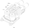
- Figure 1 shows an illustrative exploded view of the connector assembly according to an exemplary embodiment of the present invention, wherein the safety cover 100 of connector 1 is not shown
- Figure 2 shows an illustrative exploded view of the connector assembly according to an exemplary embodiment of the present invention, wherein the safety cover 100 and the housing 10 of the connector 1 are not shown
- Figure 3 shows an illustrative assembly view of the connector assembly according to an exemplary embodiment of the present invention, in which the safety cover 100 and the housing 10 of the connector 1 are not shown.
- the connector assembly mainly includes a connector 1 and a mating connector 2.
- the connector 1 includes a housing 10, a terminal 13 and a connection assembly 11.
- the mating connector 2 includes a mating housing 20 mated with the housing 10 and a mating terminal 21 electrically connected with the terminal 13.
- terminal 13 is arranged in housing 10.
- the housing 10 has a mounting port 1011.
- the connection assembly 11 is installed in the mounting port 1011 of the housing 10, and is suitable for fastening the terminal 13 to the mating terminal 21 of the mating connector 2.
- the connection assembly 11 has a first operation part 111 exposed from the housing 10, which enables the connection assembly 11 to be fastened or loosened by the first operation part 111.
- Figure 4 shows an illustrative view of a connector assembly according to an exemplary embodiment of the present invention, wherein the connection assembly 11 and the mechanical connection member 12 are in the loosened position, and the safety cover 100 is in the initial position
- Figure 5 shows an illustrative view of the connector assembly according to an exemplary embodiment of the present invention, wherein the connection assembly 11 and the mechanical connection member 12 are in the fastened position, and the safety cover 100 is in the initial position
- Figure 6 shows an illustrative view of the connector assembly according to an exemplary embodiment of the present invention, wherein the connection assembly 11 and the mechanical connection member 12 are in the fastened position, and the safety cover 100 is moved to the safe position.
- the connector 1 also includes a safety cover 100, which is slidably mounted on the housing 10.
- the first operation part 111 when the connector 1 is mated with the mating connector 2, and when the connection assembly 11 is not fastened, the first operation part 111 is in the position of interference with the safety cover 100 (for example, as shown in Figure 4 , the top surface of the first operation part 111 is higher than the inner surface of the safety cover 100), to prevent the safety cover 100 from being moved from the initial position to the safe position.
- the first operation part 111 is not covered by the safety cover 100 to allow the connection assembly 11 to be fastened or loosened by operating the first operation part 111.
- connection assembly 11 when the safety cover 100 is in the initial position, the connection assembly 11 can be fastened (as shown in Figure 5 ) or not be fastened (as shown in Figure 4 ).
- the safety cover 100 when the safety cover 100 is in the safe position, the first operation part 111 is covered by the safety cover 100 to prevent the fastened connection assembly 11 from being loosened by operating the first operation part 111.
- the connector 1 also includes a mechanical connection member 12, which is installed on the housing 10 and is suitable for threaded connection with the mating housing 20 of the mating connector 2 to fasten the housing 10 onto the mating housing 20.
- the mechanical connection member 12 has a second operation part 121 exposed from the housing 10, so that the mechanical connection member 12 is capable of being fastened or loosened by operating the second operation part 121.
- the second operation part 121 when the connector 1 is mated with the mating connector 2, and when the mechanical connection member 12 is not fastened, the second operation part 121 is in the position of interference with the safety cover 100 (for example, as shown in Figure 4 , the top surface of the second operation part 121 is higher than the inner surface of the safety cover 100) to prevent the safety cover 100 from being moved from the initial position to the safe position.
- the second operation part 121 is not covered by the safety cover 100 to allow the mechanical connection member 12 to be fastened or loosened by operating the second operation part 121.
- the mechanical connection member 12 when the safety cover 100 is in the initial position, can be fastened (as shown in Figure 5 ) or not be fastened (as shown in Figure 4 ).
- the safety cover 100 when the safety cover 100 is in the safe position, the second operation part 121 is covered by the safety cover 100 to prevent the mechanical connection member 12 from being loosened by operating the second operation part 121.
- the first operation part 111 and the second operation part 121 are in a position that does not interfere with the safety cover 100.
- the safety cover 100 can be moved from the initial position to the safe position.
- Figure 7 shows an illustrative view of the housing 10 of the connector 1 according to an exemplary embodiment of the present invention
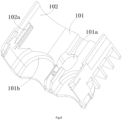
- Figure 8 shows an illustrative perspective view of the safety cover 100 of connector 1 according to an exemplary embodiment of the present invention when viewed from the top
- Figure 9 shows an illustrative perspective view of the safety cover 100 of connector 1 according to an exemplary embodiment of the present invention when viewed from the bottom
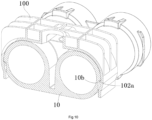
- Figure 10 shows a transverse sectional view of the housing 10 and the safety cover 100 of the connector 1 according to an exemplary embodiment of the present invention.
- the safety cover 100 comprises a top wall 101 and a pair of side walls 102.
- An operation hole 101a is formed on the top wall 101.
- a pair of side walls 102 are respectively connected to the top wall 101.
- a guide slot 10b extending in a first direction is formed on one of the outer wall surface of the housing 10 and the inner wall surface of the side wall 102 of the safety cover 100, and a guide rib 102a extending in the first direction is formed on the other.
- the guide rib 102a is buckled into the guide slot 10b and can be moved along the guide slot 10b in the first direction to guide the safety cover 100 to move between the initial position and the safety position relative to the housing 10.
- the guide slot 10b is formed on the outer wall surface of the housing 10, and the guide rib 102a is formed on the inner wall surface of the side wall 102 of the safety cover 100.
- the guide slot 10b has a guide surface 10c extending in the first direction, and the guide rib 102a slides in contact with the guide surface 10c to guide the guide rib 102a to move in the first direction.
- a limit part 101b is formed on the inner wall surface of the top wall 101 of the safety cover 100.
- the limit part 101b rests against the first operation part 111 to limit the safety cover 100 at the safe position.
- connector 1 also includes a cable 14 and an end cover 15.
- One end of the cable 14 is inserted into the housing 10 in the first direction and electrically connected with the terminal 13.
- the end cover 15 is sleeved on one end of the housing 10 to fix the cable 14 to the housing 10.
- a cable port 1014 allowing the cable 14 to be inserted in the first direction is formed on one end of the housing 10.
- the mounting port 1011 is formed on the top of the other end of the housing 10 to allow the connection assembly 11 to be inserted in the second direction perpendicular to the first direction.
- a mating port is formed at the bottom of the other end of the housing 10 to allow the connector 1 to mate with the mating connector 2 in the second direction.
- each of the safety cover 100 and the end cover 15 has a front end and a rear end which are opposite to each other in the first direction.
- the front end face of the end cover 15 rests against the rear end face of the safety cover 100 to limit the safety cover 100 at the initial position.
- the housing 10 includes at least two housing units and a connection part 10a.
- the connection part 10a is connected between two adjacent housing units of the housing 10.
- a mounting hole is formed on the connection part 10a, and the mechanical connection member 12 is installed in the mounting hole of the connection part 10a.
- connector 1 includes at least two terminals 13, at least two connection assemblies 11, at least two cables 14 and at least two end covers 15. At least two terminals 13 are respectively arranged in at least two housing units for electrical connection with at least two mating terminals 21. At least two connection assemblies 11 are respectively installed in at least two housing units for fastening at least two terminals 13 to at least two mating terminals 21. At least two cables 14 are respectively inserted into at least two housing units and electrically connected with at least two terminals 13. At least two end covers 15 are respectively sleeved on one ends of at least two housing units for fixing at least two cables 14 to at least two housing units.
- the connector 1 can include: one terminal 13, one connection assembly 11, one cable 14 and one end cover 15.
- the safety cover 100 is an integral molded part.
- the safety cover 100 can be integrally molded.
- Figure 11 shows an illustrative view of connector 1 according to an exemplary embodiment of the present invention, wherein the connection assembly 11 and the mechanical connection member 12 are in the fastened position, and the safety cover 100 is in the initial position;
- Figure 12 shows an illustrative perspective view of the mating connector 2 according to an exemplary embodiment of the present invention.
- an elastic cantilever 102b is formed on the safety cover 100, and a limit protrusion 10d is formed on the housing 10.
- the elastic cantilever 102b is in the position of interference with the limit protrusion 10d to prevent the safety cover 100 from being moved from the initial position to the safe position.
- a threaded hole 210 is formed on the mating terminal 21 or a threaded hole 210 is formed on the mating connection assembly 22 assembled with the mating terminal 21, and the connection assembly 11 includes a threaded connection member 110 connected to the threaded hole 210.
- a threaded connection hole 220 is formed on the mating housing 20, and the mechanical connection member 12 of the connector 1 has a threaded connection part 120 connected to the threaded connection hole 220.
- the mating connector 2 also includes an inner housing 200 made of insulation material.
- the inner housing 200 is installed in the mating housing 20.
- the housing 10 and the mating housing 20 are conductive housings made of conductive material.
- the mating housing 20 has a flange portion 20a extending radially, and the threaded connection hole 220 is formed on the flange portion 20a.
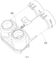
- Figure 13 shows an illustrative assembly view of the housing 10 and the high-voltage interlock 16 of the connector 1 according to an exemplary embodiment of the present invention
- Figure 14 shows an illustrative perspective view of the housing 10 of the connector 1 according to an exemplary embodiment of the present invention
- Figure 15 shows an illustrative perspective view of the high-voltage interlock 16 of the connector 1 according to an exemplary embodiment of the present invention
- Figure 16 shows an illustrative view of high-voltage interlock 16 and safety cover 100 of connector 1 and high-voltage interlock 26 of connector 2 according to an exemplary embodiment of the present invention, wherein the safety cover 100 is in the initial position and the high-voltage interlock 16 is in the disconnected position.
- a connector 1 is also disclosed.
- the connector 1 includes: a housing 10, a terminal 13, a connection assembly 11, a safety cover 100 and a high-voltage interlock 16.
- the housing 10 is formed with a slot 1016 and a mounting port 1011.
- the terminal 13 is arranged in the housing 10.
- the connection assembly 11 is installed in the mounting port 1011 of the housing 10 and is suitable for fastening the terminal 13 to the mating terminal 21 of the mating connector 2.
- the safety cover 100 is movably mounted on the housing 10 and can be moved between the initial position where the connection assembly 11 is not covered by the safety cover 100 and the safety position where the connection assembly 11 is covered by the safety cover 100.
- the high voltage interlock 16 is movably installed in the slot 1016 and can be moved between the connected position where the high voltage interlock 16 is engaged with the mating high voltage interlock 26 of the mating connector 2 and the disconnected position where the high voltage interlock 16 is separated from the mating high voltage interlock 26.
- connection assembly 11 when the connector 1 is mated with the mating connector 2, and when the connection assembly 11 is not fastened, the connection assembly 11 is in the position of interference with the safety cover 100 to prevent the safety cover 100 from being moved from the initial position to the safe position.
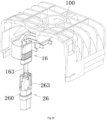
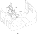
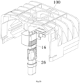
- Figure 19 shows the sectional view of a high-voltage interlock 16 and a safety cover 100 of a connector 1 and a mating high-voltage interlock 26 of a mating connector 2 according to an exemplary embodiment of the present invention, wherein the safety cover 100 is in the safe position and the high-voltage interlock 16 is in the connected position;
- Figure 20 shows an illustrative view of a high-voltage interlock 16 and a safety cover 100 of a connector 1 and a mating high-voltage interlock 26 of a mating connector 2 according to an exemplary embodiment of the present invention, wherein the safety cover 100 is in the safe position and the high-voltage interlock 16 is in the connected position;
- Figure 21 shows the sectional view of a high-voltage interlock 16 and a safety cover 100 of a connector 1 and a mating high-voltage interlock 26 of a mating connector 2 according to an exemplary embodiment of the present invention, wherein the safety cover 100 is in the safe position and the high-voltage interlock 16 is
- the safety cover 100 and the high voltage interlock 16 are connected in a sliding way to make them linked according to the following relationship: when the safety cover 100 is moved to the initial position, the high voltage interlock 16 is moved to the disconnected position; and when the safety cover 100 is moved to the safety position, the high-voltage interlock 16 is moved to the connected position.
- Figure 17 shows an illustrative assembly view of the high-voltage interlock 16 and the safety cover 100 of the connector 1 according to an exemplary embodiment of the present invention, wherein the safety cover 100 is in the initial position;
- Figure 18 shows an illustrative view of the safety cover 100 of connector 1 according to an exemplary embodiment of the present invention when viewed from the bottom, showing the structure connected with the high-voltage interlock 16.
- the high-voltage interlock 16 includes an insulator 161 and two detection terminals 163.
- the two detection terminals 163 are fixed to the insulator 161 for electrical connection to positive and negative electrodes of a high-voltage interlock circuit (not shown).
- the two detection terminals 163 of the high-voltage interlock 16 are electrically connected with the mating detection terminal 263 in the mating high-voltage interlock 26 to turn on the high-voltage interlock circuit.
- the two detection terminals 163 are separated from the mating detection terminal 263 to cut off the high-voltage interlock circuit.
- connection assembly 11 when the connector 1 is mated with the mating connector 2, and when the connection assembly 11 is not fastened, the connection assembly 11 is in the position of interference with the safety cover 100, so that the safety cover 100 cannot be moved from the initial position to the safe position. Therefore, when the connection assembly 11 is not fastened, the high-voltage interlock 16 is always in the disconnected position. Only when the connection assembly 11 is fastened, the high-voltage interlock 16 can be moved to the connected position.
- the high-voltage interlock circuit is turned on only after the high-voltage terminals (terminal 13 and terminal 21) are electrically connected; During the separation of connector 1 and mating connector 2, the high-voltage interlock circuit is cut off before the high-voltage terminals (terminal 13 and terminal 21) are separated. In this way, the high-voltage terminals (terminal 13 and terminal 21) can be avoided from being hot plugged and unplugged, and the use safety of the connector is improved.
- the safety cover 100 is configured to be moved between the initial position and the safety position in the first direction (the horizontal direction in the figures).
- the high-voltage interlock 16 is configured to be moved between the connected position and the disconnected position in the second direction (the vertical direction in the figures) perpendicular to the first direction.
- a guide slot 10b extending in the first direction is formed on one of the inner wall surface of the safety cover 100 and the outer wall surface of the housing 10, and a guide rib 102a extending in the first direction is formed on the other.
- the guide slot 10b is slidably mated with the guide rib 102a to guide the safety cover 100 to move between the initial position and the safety position in the first direction relative to the housing 10.
- the slot 1016 on the housing 10 extends in the second direction
- the insulator 160 of the high-voltage interlock 16 includes the first part 161 extending in the second direction.
- the first part 161 of the insulator 160 is slidably mated with the slot 1016 of the housing 10 to guide the high-voltage interlock 16 to move between the connected position and the disconnected position in the second direction relative to the housing 10.
- the insulator 160 of the high-voltage interlock 16 also includes a second part 162 connected with the first part 161, and the second part 162 is located outside the housing 10.
- the detection terminal 163 is fixed to the first part 161 of the insulator 160, and the second part 162 of the insulator 160 is slidably connected with the safety cover 100.
- a pair of support walls 103 is formed on the inner wall surface of the top wall 101 of the safety cover 100, and a part of the second part 162 of the insulator 160 is arranged in a gap between the pair of support walls 103.
- a chute 1620 is formed on each side of the second part 162 of the insulator 160.
- the pair of support walls 103 are respectively formed with convex parts 103a which are slidably connected with the chutes 1620.
- the chute 1620 includes a main part 1623 extending a predetermined length in a direction inclined to the first direction to convert the movement of the safety cover 100 in the first direction (the horizontal direction in the figure) into the movement of the high-voltage interlock 16 in the second direction (the vertical direction in the figure).
- the chute 1620 also includes a first end part 1621 and a second end part 1622 which are respectively connected with the two ends of the main part 1623 of the chute 1620, and the first end part 1621 and the second end part 1622 extend in the first direction.
- the convex part 103a is moved to the first end part 1621 of the chute 1620.
- the convex part 103a is moved to the second end part 1622 of the chute 1620.
- the high-voltage interlock 16 also includes a sealing ring 164.
- the seal ring 164 is sleeved on the first part 161 of the insulator 160 to seal the gap between the first part 161 of the insulator 160 and the slot 1016 of the housing 10.
- the mating connector 2 includes an inner housing 200 made of insulation material, and the mating high-voltage interlock 26 is fixedly installed in the inner housing 200.
- the mating high-voltage interlock 26 includes an insulator 260 and a mating detection terminal 263 arranged in the insulator 260.
- the mating detection terminal 263 is bridged between the two detection terminals 163 to connect the two detection terminals 163.
- a connector assembly which includes a connector 1 and a mating connector 2 suitable for mating with connector 1.
- the mating connector 2 includes a mating housing 20, a mating terminal 21 and a mating high-voltage interlock 26.
- the mating housing 20 is suitable for mating with the housing 10 of the connector 1.
- the mating terminal 21 is arranged in the mating housing 20 for electrical connection with the terminal 13 of the connector 1.
- the mating high-voltage interlock 26 is arranged in the mating housing 20 for mating with the high-voltage interlock 16 of the connector 1.
- a connector 1 which includes a housing 10, a mechanical connection member 12 and a safety cover 100.
- the safety cover 100 is slidably mounted on the housing 10.
- the mechanical connection member 12 is mounted on the housing 10 and is suitable for threaded connection with the mating housing 20 of the mating connector 2 to fasten the housing 10 to the mating housing 20.
- the mechanical connection member 12 has a second operation part 121 exposed from the housing 10, enabling the mechanical connection member 12 to be fastened or loosened by operating the second operation part 121.
- the second operation part 121 is in the position of interference with the safety cover 100 to prevent the safety cover 100 from being moved from the initial position to the safe position.
- a connector 1 which includes: a housing 10, a terminal 13, a connection assembly 11 and a safety cover 100.
- the terminal 13 is arranged in the housing 10.
- the connection assembly 11 is installed in the housing 10 and is suitable for fastening the terminal 13 to a mating terminal 21 of a mating connector 2.
- the safety cover 100 is slidably mounted on the housing 10.
- the connection assembly 11 has a first operation part 111 exposed from the housing 10, which enables the connection assembly 11 to be fastened or loosened by operating the first operation part 111.
- the first operation part 111 is in the position of interference with the safety cover 100 to prevent the safety cover 100 from being moved from the initial position to the safe position.
- the first operation part 111 is in a position that does not interfere with the safety cover 100 to allow the safety cover 100 to be moved from the initial position to the safe position.
- the safety cover 100 When the safety cover 100 is in the safe position, the first operation part 111 is covered by the safety cover 100 to prevent the connection assembly 11 from being loosened by operating the first operation part 111.
Landscapes
- Details Of Connecting Devices For Male And Female Coupling (AREA)
- Connector Housings Or Holding Contact Members (AREA)
Abstract
Description
- This application claims the benefit of Chinese Patent Application No.
CN202210224214.1 filed on March 9, 2022 CN202220498838.8 filed on March 9, 2022 - The present invention relates to a connector and a connector assembly including the connector.
- In the prior art, the connector at the cable end usually includes a housing, a terminal, a connection assembly and a cable. The terminal is arranged in the housing, and the cable extends into the housing and is electrically connected with the terminal. The connection assembly is installed in the housing, which is used to fasten the terminal to a mating terminal of a mating connector, so that the terminal is electrically connected with the mating terminal.
- In the prior art, when the connector is mated with the mating connector, there is a lack of safety protection device to judge whether the connection assembly has been fastened and prevent the fastened connection assembly from being accidentally loosened, which reduces the use safety of the connector.
- In addition, in the prior art, in order to detect the connection state between the terminal of the connector and the mating terminal of the mating connector, it is also necessary to set a high-voltage interlock (or called a detection connector) and a mating high-voltage interlock (or called a mating detection connector) on the connector and the mating connector respectively. However, the existing high-voltage interlock is fixed on the housing of the connector, so there is a risk that the high-voltage interlock will be mated with the mating high-voltage interlock before the terminal of the connector is electrically connected with the mating terminal of the mating connector, which also reduces the use safety of the connector.
- The present invention has been made to overcome or alleviate at least one aspect of the above mentioned disadvantages.
- According to an aspect of the present invention, there is provided a connector. The connector comprises of: a housing which is formed with a slot and a mounting port; a connection assembly which is installed in the mounting port of the housing and is adapted to fasten a terminal of the connector to a mating terminal of a mating connector; a safety cover which is movably mounted on the housing and is capable of being moved between an initial position where the connection assembly is not covered by the safety cover and a safety position where the connection assembly is covered by the safety cover; and a high-voltage interlock which is movably installed in the slot and is capable of being moved between a connected position where the high-voltage interlock is engaged with a mating high-voltage interlock of the mating connector and a disconnected position where the high-voltage interlock is separated from the mating high-voltage interlock. In the process of mating the connector with the mating connector, when the connection assembly is not fastened, the connection assembly is in a position that interferes with the safety cover to prevent the safety cover from being moved from the initial position to the safety position. The safety cover is slidably connected with the high-voltage interlock, so that the safety cover and the high-voltage interlock are linked according to the following relationship: when the safety cover is moved to the initial position, the high-voltage interlock is moved to the disconnected position; and when the safety cover is moved to the safety position, the high-voltage interlock is moved to the connected position.
- According to an exemplary embodiment of the present invention, the high-voltage interlock comprises of: an insulator; and two detection terminals which are fixed to the insulator and are used to electrically connect to positive and negative electrodes of a high-voltage interlock circuit respectively. When the high-voltage interlock is moved to the connected position, the two detection terminals of the high-voltage interlock are electrically connected with a mating detection terminal of the mating high-voltage interlock to turn on the high-voltage interlock circuit; when the high-voltage interlock is moved to the disconnected position, the two detection terminals are separated from the mating detection terminal to cut off the high-voltage interlock circuit.
- According to another exemplary embodiment of the present invention, the safety cover is configured to be moved between the initial position and the safety position in a first direction; the high-voltage interlock is configured to be moved between the connected position and the disconnected position in a second direction perpendicular to the first direction.
- According to another exemplary embodiment of the present invention, a guide slot extending in the first direction is formed on one of the inner wall surface of the safety cover and the outer wall surface of the housing, and a guide rib extending in the first direction is formed on the other; the guide slot is slidably mated with the guide rib to guide the safety cover to move between the initial position and the safety position in the first direction relative to the housing.
- According to another exemplary embodiment of the present invention, the slot on the housing extends in the second direction, and the insulator of the high-voltage interlock comprises a first part extending in the second direction; the first part of the insulator is slidably mated with the slot of the housing to guide the high-voltage interlock to move between the connected position and the disconnected position in the second direction relative to the housing.
- According to another exemplary embodiment of the present invention, the insulator of the high-voltage interlock further comprises a second part which is connected with the first part and is located outside the housing; the detection terminal is fixed to the first part of the insulator, and the second part of the insulator is slidably connected with the safety cover.
- According to another exemplary embodiment of the present invention, a pair of support walls are formed on the inner wall surface of the safety cover, and a part of the second part of the insulator is arranged in a gap between the pair of support walls; a chute is formed on each side of the second part of the insulator facing the support wall, and a convex part is formed on the support wall and is slidably connected with the chute; the chute comprises a main part extending a predetermined length in a direction inclined to the first direction to convert the movement of the safety cover in the first direction into the movement of the high-voltage interlock in the second direction.
- According to another exemplary embodiment of the present invention, the chute also includes a first end part and a second end part which are respectively connected with the two ends of the main part of the chute, and the first end part and the second end part extend along the first direction; when the safety cover is moved to the initial position, the convex part is moved into the first end part of the chute; when the safety cover is moved to the safety position, the convex part is moved into the second end part of the chute.
- According to another exemplary embodiment of the present invention, the high-voltage interlock also includes a sealing ring, which is sleeved on the first part of the insulator and used to seal a gap between the first part of the insulator and the slot of the housing.
- According to another exemplary embodiment of the present invention, the connection assembly has a first operation part exposed from the housing, so that the connection assembly is capable of being fastened or loosened by operating the first operation part; in the process of mating the connector with the mating connector, when the connection assembly is not fastened, the first operation part is in a position that interferes with the safety cover to prevent the safety cover from being moved from the initial position to the safe position; when the safety cover is in the initial position, the first operation part is not covered by the safety cover to allow the connection assembly to be fastened or loosened by operating the first operation part; when the safety cover is in the safety position, the first operation part is covered by the safety cover to prevent the connection assembly from being loosened by operating the first operation part.
- According to another exemplary embodiment of the present invention, in the process of mating the connector with the mating connector, when the connection assembly has been fastened, the first operation part is in a position that does not interfere with the safety cover, to allow the safety cover to be moved from the initial position to the safe position.
- According to another exemplary embodiment of the present invention, the connector further comprises a mechanical connection member which is installed on the housing and is suitable for threaded connection with a mating housing of the mating connector to fasten the housing to the mating housing. The mechanical connection member has a second operation part exposed from the housing, so that the mechanical connection member is capable of being fastened or loosened by operating the second operation part; in the process of mating the connector with the mating connector, when the mechanical connection member is not fastened, the second operation part is in a position of interference with the safety cover to prevent the safety cover from being moved from the initial position to the safe position; when the safety cover is in the initial position, the second operation part is not covered by the safety cover to allow the mechanical connection member to be fastened or loosened by operating the second operation part; when the safety cover is in the safety position, the second operation part is covered by the safety cover to prevent the mechanical connection member from being loosened by operating the second operation part.
- According to another exemplary embodiment of the present invention, in the process of mating the connector with the mating connector, when the connection assembly and the mechanical connection member are fastened, the first operation part and the second operation part are in a position that does not interfere with the safety cover, to allow the safety cover to be moved from the initial position to the safe position.
- According to another exemplary embodiment of the present invention, the safety cover comprises of: a top wall which is formed with an operation hole; and a pair of side walls which are respectively connected to both sides of the top wall. When the safety cover is in the initial position, the first operation part is located outside the safety cover, and the second operation part is exposed from the safety cover through the operation hole.
- According to another exemplary embodiment of the present invention, a limit part is formed on the inner wall surface of the top wall of the safety cover; when the safety cover is moved from the initial position to the safe position, the limit part rests against the first operation part to limit the safety cover at the safe position.
- According to another exemplary embodiment of the present invention, the connector further comprises a terminal which is arranged in the housing for electrical connection with the mating terminal of the mating connector.
- According to another exemplary embodiment of the present invention, the connector further comprises of: a cable, one end of which is inserted into the housing in the first direction and electrically connected with the terminal; and an end cover which is sleeved on one end of the housing and is used to fix the cable to the housing.
- According to another exemplary embodiment of the present invention, a cable port allowing the cable to be inserted in the first direction is formed at one end of the housing; the mounting port is formed on the top of the other end of the housing to allow the connection assembly to be inserted in the second direction perpendicular to the first direction; a mating port is formed on the bottom of the other end of the housing to allow the connector to mate with the mating connector in the second direction.
- According to another exemplary embodiment of the present invention, an elastic cantilever is formed on the safety cover, and a limit protrusion is formed on the housing; when the housing is not mated with the mating housing and the safety cover is in the initial position, the elastic cantilever is in a position of interference with the limit protrusion to prevent the safety cover from being moved from the initial position to the safety position.
- According to another exemplary embodiment of the present invention, when the housing has been mated with the mating housing and the safety cover is in the initial position, the elastic cantilever is pushed by an unlocking part of the mating housing to a position that does not interfere with the limit protrusion, so that the movement of the safety cover will not be hindered by the limit protrusion.
- According to another aspect of the present invention, there is provided a connector assembly. The connector assembly comprises of: the above connector; and a mating connector adapted to mate with the connector. The mating connector comprises of: a mating housing which is suitable for mating with the housing of the connector; a mating terminal which is arranged in the mating housing for electrical connection with the terminal of the connector; and a mating high-voltage interlock which is arranged in the mating housing for mating with the high-voltage interlock of the connector.
- In the above-mentioned exemplary embodiments according to the present invention, the high-voltage interlock is linked with the safety cover, so it can be ensured that the high-voltage interlock is always in a state of separation from the mating high-voltage interlock before the terminal of the connector is electrically connected to the mating terminal of the mating connector, thus improving the use safety of the connector.
- In addition, in the aforementioned exemplary embodiments according to the present invention, the safety cover can not only reliably prevent the fastened connection assembly from being accidentally loosened, but also can conveniently judge whether the connection assembly have been fastened, thus improving the use safety of the connector.
- The above and other features of the present invention will become more apparent by describing in detail exemplary embodiments thereof with reference to the accompanying drawings, in which:
-
Figure 1 shows an illustrative exploded view of a connector assembly according to an exemplary embodiment of the present invention, in which the safety cover of the connector is not shown; -
Figure 2 shows an illustrative exploded view of the connector assembly according to an exemplary embodiment of the present invention, in which the safety cover and housing of the connector are not shown; -
Figure 3 shows an illustrative assembly view of the connector assembly according to an exemplary embodiment of the present invention, wherein the safety cover and housing of the connector are not shown; -
Figure 4 shows an illustrative view of a connector assembly according to an exemplary embodiment of the present invention, wherein the connection assembly and the mechanical connection member are in the loosened position, and the safety cover is in the initial position; -
Figure 5 shows an illustrative view of the connector assembly according to an exemplary embodiment of the present invention, wherein the connection assembly and the mechanical connection member are in the fastened position, and the safety cover is in the initial position; -
Figure 6 shows an illustrative view of the connector assembly according to an exemplary embodiment of the present invention, wherein the connection assembly and the mechanical connection member are in the fastened position, and the safety cover is moved to the safe position; -
Figure 7 shows an illustrative view of a connector housing according to an exemplary embodiment of the present invention; -
Figure 8 shows an illustrative perspective view of the safety cover of the connector according to an exemplary embodiment of the present invention when viewed from the top; -
Figure 9 shows an illustrative perspective view of the safety cover of the connector according to an exemplary embodiment of the present invention when viewed from the bottom; -
Figure 10 shows a transverse sectional view of a connector housing and a safety cover according to an exemplary embodiment of the present invention; -
Figure 11 shows an illustrative view of a connector according to an exemplary embodiment of the present invention, wherein the connection assembly and mechanical connection member are in the fastened position, and the safety cover is in the initial position; -
Figure 12 shows an illustrative perspective view of a mating connector according to an exemplary embodiment of the present invention; -
Figure 13 shows an illustrative assembly view of the connector housing and the high-voltage interlock according to an exemplary embodiment of the present invention; -
Figure 14 shows an illustrative perspective view of a connector housing according to an exemplary embodiment of the present invention; -
Figure 15 shows an illustrative perspective view of a high-voltage interlock of a connector according to an exemplary embodiment of the present invention; -
Figure 16 shows an illustrative view of a high-voltage interlock and safety cover of a connector and a mating high-voltage interlock of a mating connector according to an exemplary embodiment of the present invention, wherein the safety cover is in the initial position and the high-voltage interlock is in the disconnected position; -
Figure 17 shows an illustrative assembly view of the high-voltage interlock and the safety cover of the connector according to an exemplary embodiment of the present invention, wherein the safety cover is in the initial position; -
Figure 18 shows an illustrative view of the safety cover of the connector according to an exemplary embodiment of the present invention when viewed from the bottom, in which the structure connected with the high-voltage interlock is shown; -
Figure 19 shows the sectional view of the high-voltage interlock and safety cover of the connector and the mating high-voltage interlock of the mating connector according to an exemplary embodiment of the present invention, wherein the safety cover is in the safe position and the high-voltage interlock is in the connected position; -
Figure 20 shows an illustrative view of the high-voltage interlock and safety cover of the connector and the mating high-voltage interlock of the mating connector according to an exemplary embodiment of the present invention, wherein the safety cover is in the safe position and the high-voltage interlock is in the connected position; and -
Figure 21 shows the sectional view of the high-voltage interlock and safety cover of the connector and the mating high-voltage interlock of the mating connector according to an exemplary embodiment of the present invention, wherein the safety cover is in the safe position and the high-voltage interlock is in the connected position. - Exemplary embodiments of the present disclosure will be described hereinafter in detail with reference to the attached drawings, wherein the like reference numerals refer to the like elements. The present disclosure may, however, be embodied in many different forms and should not be construed as being limited to the embodiment set forth herein; rather, these embodiments are provided so that the present disclosure will be thorough and complete, and will fully convey the concept of the disclosure to those skilled in the art.
- In the following detailed description, for purposes of explanation, numerous specific details are set forth in order to provide a thorough understanding of the disclosed embodiments. It will be apparent, however, that one or more embodiments may be practiced without these specific details. In other instances, well-known structures and devices are schematically shown in order to simplify the drawing.
- According to a general concept of the present invention, there is provided a connector. The connector comprises of: a housing which is formed with a slot and a mounting port; a connection assembly which is installed in the mounting port of the housing and is adapted to fasten a terminal of the connector to a mating terminal of a mating connector; a safety cover which is movably mounted on the housing and is capable of being moved between an initial position where the connection assembly is not covered by the safety cover and a safety position where the connection assembly is covered by the safety cover; and a high-voltage interlock which is movably installed in the slot and is capable of being moved between a connected position where the high-voltage interlock is engaged with a mating high-voltage interlock of the mating connector and a disconnected position where the high-voltage interlock is separated from the mating high-voltage interlock. In the process of mating the connector with the mating connector, when the connection assembly is not fastened, the connection assembly is in a position that interferes with the safety cover to prevent the safety cover from being moved from the initial position to the safety position. The safety cover is slidably connected with the high-voltage interlock, so that the safety cover and the high-voltage interlock are linked according to the following relationship: when the safety cover is moved to the initial position, the high-voltage interlock is moved to the disconnected position; and when the safety cover is moved to the safety position, the high-voltage interlock is moved to the connected position.
- According to another general concept of the present invention, there is provided a connector assembly. The connector assembly comprises of: the above connector; and a mating connector adapted to mate with the connector. The mating connector comprises of: a mating housing which is suitable for mating with the housing of the connector; a mating terminal which is arranged in the mating housing for electrical connection with the terminal of the connector; and a mating high-voltage interlock which is arranged in the mating housing for mating with the high-voltage interlock of the connector.
-
Figure 1 shows an illustrative exploded view of the connector assembly according to an exemplary embodiment of the present invention, wherein thesafety cover 100 ofconnector 1 is not shown;Figure 2 shows an illustrative exploded view of the connector assembly according to an exemplary embodiment of the present invention, wherein thesafety cover 100 and thehousing 10 of theconnector 1 are not shown;Figure 3 shows an illustrative assembly view of the connector assembly according to an exemplary embodiment of the present invention, in which thesafety cover 100 and thehousing 10 of theconnector 1 are not shown. - As shown in
Figures 1 to 3 , in the illustrated embodiment, the connector assembly mainly includes aconnector 1 and amating connector 2. Theconnector 1 includes ahousing 10, a terminal 13 and aconnection assembly 11. Themating connector 2 includes amating housing 20 mated with thehousing 10 and amating terminal 21 electrically connected with the terminal 13. - As shown in
Figures 1 to 3 , in the illustrated embodiment, terminal 13 is arranged inhousing 10. Thehousing 10 has a mountingport 1011. Theconnection assembly 11 is installed in the mountingport 1011 of thehousing 10, and is suitable for fastening the terminal 13 to themating terminal 21 of themating connector 2. Theconnection assembly 11 has afirst operation part 111 exposed from thehousing 10, which enables theconnection assembly 11 to be fastened or loosened by thefirst operation part 111. -
Figure 4 shows an illustrative view of a connector assembly according to an exemplary embodiment of the present invention, wherein theconnection assembly 11 and themechanical connection member 12 are in the loosened position, and thesafety cover 100 is in the initial position;Figure 5 shows an illustrative view of the connector assembly according to an exemplary embodiment of the present invention, wherein theconnection assembly 11 and themechanical connection member 12 are in the fastened position, and thesafety cover 100 is in the initial position;Figure 6 shows an illustrative view of the connector assembly according to an exemplary embodiment of the present invention, wherein theconnection assembly 11 and themechanical connection member 12 are in the fastened position, and thesafety cover 100 is moved to the safe position. - As shown in
Figures 1 to 6 , in the illustrated embodiment, theconnector 1 also includes asafety cover 100, which is slidably mounted on thehousing 10. - As shown in
Figure 4 , in the illustrated embodiment, when theconnector 1 is mated with themating connector 2, and when theconnection assembly 11 is not fastened, thefirst operation part 111 is in the position of interference with the safety cover 100 (for example, as shown inFigure 4 , the top surface of thefirst operation part 111 is higher than the inner surface of the safety cover 100), to prevent thesafety cover 100 from being moved from the initial position to the safe position. - As shown in
Figures 4 and5 , in the illustrated embodiment, when thesafety cover 100 is in the initial position, thefirst operation part 111 is not covered by thesafety cover 100 to allow theconnection assembly 11 to be fastened or loosened by operating thefirst operation part 111. - Please note that, as shown in
Figures 4 and5 , in an exemplary embodiment of the present invention, when thesafety cover 100 is in the initial position, theconnection assembly 11 can be fastened (as shown inFigure 5 ) or not be fastened (as shown inFigure 4 ). - As shown in
Figure 6 , in the illustrated embodiment, when thesafety cover 100 is in the safe position, thefirst operation part 111 is covered by thesafety cover 100 to prevent the fastenedconnection assembly 11 from being loosened by operating thefirst operation part 111. - As shown in
Figures 1 to 6 , in the illustrated embodiment, theconnector 1 also includes amechanical connection member 12, which is installed on thehousing 10 and is suitable for threaded connection with themating housing 20 of themating connector 2 to fasten thehousing 10 onto themating housing 20. - As shown in
Figures 1 to 6 , in the illustrated embodiment, themechanical connection member 12 has asecond operation part 121 exposed from thehousing 10, so that themechanical connection member 12 is capable of being fastened or loosened by operating thesecond operation part 121. - As shown in
Figure 4 , in the illustrated embodiment, when theconnector 1 is mated with themating connector 2, and when themechanical connection member 12 is not fastened, thesecond operation part 121 is in the position of interference with the safety cover 100 (for example, as shown inFigure 4 , the top surface of thesecond operation part 121 is higher than the inner surface of the safety cover 100) to prevent thesafety cover 100 from being moved from the initial position to the safe position. - As shown in
Fig. 4 andFig. 5 , in the illustrated embodiment, when thesafety cover 100 is in the initial position, thesecond operation part 121 is not covered by thesafety cover 100 to allow themechanical connection member 12 to be fastened or loosened by operating thesecond operation part 121. - Please note that, as shown in
Figures 4 and5 , in an exemplary embodiment of the present invention, when thesafety cover 100 is in the initial position, themechanical connection member 12 can be fastened (as shown inFigure 5 ) or not be fastened (as shown inFigure 4 ). - As shown in
Figure 6 , in the illustrated embodiment, when thesafety cover 100 is in the safe position, thesecond operation part 121 is covered by thesafety cover 100 to prevent themechanical connection member 12 from being loosened by operating thesecond operation part 121. - As shown in
Figure 4 , in the illustrated embodiment, when theconnector 1 is mated with themating connector 2, and when either of theconnection assembly 11 and themechanical connection member 12 is not fastened, one of thefirst operation part 111 and thesecond operation part 121 will be in the position of interference with thesafety cover 100, so that thesafety cover 100 cannot be moved from the initial position to the safe position. - As shown in
Figure 5 andFigure 6 , in the illustrated embodiment, when theconnector 1 is mated with themating connector 2, and when theconnection assembly 11 and themechanical connection member 12 are fastened, thefirst operation part 111 and thesecond operation part 121 are in a position that does not interfere with thesafety cover 100. At this time, thesafety cover 100 can be moved from the initial position to the safe position. -
Figure 7 shows an illustrative view of thehousing 10 of theconnector 1 according to an exemplary embodiment of the present invention;Figure 8 shows an illustrative perspective view of thesafety cover 100 ofconnector 1 according to an exemplary embodiment of the present invention when viewed from the top;Figure 9 shows an illustrative perspective view of thesafety cover 100 ofconnector 1 according to an exemplary embodiment of the present invention when viewed from the bottom;Figure 10 shows a transverse sectional view of thehousing 10 and thesafety cover 100 of theconnector 1 according to an exemplary embodiment of the present invention. - As shown in
Figures 1 to 10 , in the illustrated embodiment, thesafety cover 100 comprises atop wall 101 and a pair ofside walls 102. Anoperation hole 101a is formed on thetop wall 101. A pair ofside walls 102 are respectively connected to thetop wall 101. When thesafety cover 100 is in the initial position, thefirst operation part 111 is located outside thesafety cover 100, and thesecond operation part 121 is exposed from thesafety cover 100 through theoperation hole 101a. - As shown in
Figures 1 to 10 , in the illustrated embodiment, aguide slot 10b extending in a first direction is formed on one of the outer wall surface of thehousing 10 and the inner wall surface of theside wall 102 of thesafety cover 100, and aguide rib 102a extending in the first direction is formed on the other. Theguide rib 102a is buckled into theguide slot 10b and can be moved along theguide slot 10b in the first direction to guide thesafety cover 100 to move between the initial position and the safety position relative to thehousing 10. - As shown in
Figures 1 to 10 , in the illustrated embodiment, theguide slot 10b is formed on the outer wall surface of thehousing 10, and theguide rib 102a is formed on the inner wall surface of theside wall 102 of thesafety cover 100. Theguide slot 10b has aguide surface 10c extending in the first direction, and theguide rib 102a slides in contact with theguide surface 10c to guide theguide rib 102a to move in the first direction. - As shown in
Figures 1 to 10 , in the illustrated embodiment, alimit part 101b is formed on the inner wall surface of thetop wall 101 of thesafety cover 100. When thesafety cover 100 is moved from the initial position to the safe position, thelimit part 101b rests against thefirst operation part 111 to limit thesafety cover 100 at the safe position. - As shown in
Figures 1 to 10 , in the illustrated embodiment,connector 1 also includes acable 14 and anend cover 15. One end of thecable 14 is inserted into thehousing 10 in the first direction and electrically connected with the terminal 13. Theend cover 15 is sleeved on one end of thehousing 10 to fix thecable 14 to thehousing 10. - As shown in
Figures 1 to 10 , in the illustrated embodiment, acable port 1014 allowing thecable 14 to be inserted in the first direction is formed on one end of thehousing 10. The mountingport 1011 is formed on the top of the other end of thehousing 10 to allow theconnection assembly 11 to be inserted in the second direction perpendicular to the first direction. A mating port is formed at the bottom of the other end of thehousing 10 to allow theconnector 1 to mate with themating connector 2 in the second direction. - As shown in
Figures 1 to 10 , in the illustrated embodiment, each of thesafety cover 100 and theend cover 15 has a front end and a rear end which are opposite to each other in the first direction. When thesafety cover 100 is moved from the safe position to the initial position, the front end face of theend cover 15 rests against the rear end face of thesafety cover 100 to limit thesafety cover 100 at the initial position. - As shown in
Figures 1 to 10 , in the illustrated embodiment, thehousing 10 includes at least two housing units and aconnection part 10a. Theconnection part 10a is connected between two adjacent housing units of thehousing 10. A mounting hole is formed on theconnection part 10a, and themechanical connection member 12 is installed in the mounting hole of theconnection part 10a. - As shown in
Figures 1 to 10 , in the illustrated embodiment,connector 1 includes at least twoterminals 13, at least twoconnection assemblies 11, at least twocables 14 and at least two end covers 15. At least twoterminals 13 are respectively arranged in at least two housing units for electrical connection with at least twomating terminals 21. At least twoconnection assemblies 11 are respectively installed in at least two housing units for fastening at least twoterminals 13 to at least twomating terminals 21. At least twocables 14 are respectively inserted into at least two housing units and electrically connected with at least twoterminals 13. At least two end covers 15 are respectively sleeved on one ends of at least two housing units for fixing at least twocables 14 to at least two housing units. - However, the present invention is not limited to the illustrated embodiment. For example, the
connector 1 can include: oneterminal 13, oneconnection assembly 11, onecable 14 and oneend cover 15. - As shown in
Figures 1 to 10 , in the illustrated embodiment, thesafety cover 100 is an integral molded part. For example, thesafety cover 100 can be integrally molded. -
Figure 11 shows an illustrative view ofconnector 1 according to an exemplary embodiment of the present invention, wherein theconnection assembly 11 and themechanical connection member 12 are in the fastened position, and thesafety cover 100 is in the initial position;Figure 12 shows an illustrative perspective view of themating connector 2 according to an exemplary embodiment of the present invention. - As shown in
Figures 1 to 12 , in the illustrated embodiment, anelastic cantilever 102b is formed on thesafety cover 100, and alimit protrusion 10d is formed on thehousing 10. As shown inFigure 11 , when thehousing 10 is not mated with themating housing 20 and thesafety cover 100 is in the initial position, theelastic cantilever 102b is in the position of interference with thelimit protrusion 10d to prevent thesafety cover 100 from being moved from the initial position to the safe position. - As shown in
Figures 1 to 12 , in the illustrated embodiment, when thehousing 10 has been mated with themating housing 20 and thesafety cover 100 is in the initial position, theelastic cantilever 102b is pushed by the unlockingpart 20d on themating housing 20 to a position that does not interfere with thelimit protrusion 10d, so that the movement of thesafety cover 100 will not be hindered by thelimit protrusion 10d. - As shown in
Figures 1 to 12 , in the illustrated embodiment, when thehousing 10 has been mated with themating housing 20 and thesafety cover 100 has been moved to the safe position, the free end of theelastic cantilever 102b rests against thestop part 20b of themating housing 20 to limit thesafety cover 100 at the safe position. - As shown in
Figures 1 to 12 , in the illustrated embodiment, a threadedhole 210 is formed on themating terminal 21 or a threadedhole 210 is formed on themating connection assembly 22 assembled with themating terminal 21, and theconnection assembly 11 includes a threadedconnection member 110 connected to the threadedhole 210. A threadedconnection hole 220 is formed on themating housing 20, and themechanical connection member 12 of theconnector 1 has a threadedconnection part 120 connected to the threadedconnection hole 220. - As shown in
Figures 1 to 12 , in the illustrated embodiment, themating connector 2 also includes aninner housing 200 made of insulation material. Theinner housing 200 is installed in themating housing 20. In the illustrated embodiment, thehousing 10 and themating housing 20 are conductive housings made of conductive material. Themating housing 20 has aflange portion 20a extending radially, and the threadedconnection hole 220 is formed on theflange portion 20a. -
Figure 13 shows an illustrative assembly view of thehousing 10 and the high-voltage interlock 16 of theconnector 1 according to an exemplary embodiment of the present invention;Figure 14 shows an illustrative perspective view of thehousing 10 of theconnector 1 according to an exemplary embodiment of the present invention;Figure 15 shows an illustrative perspective view of the high-voltage interlock 16 of theconnector 1 according to an exemplary embodiment of the present invention;Figure 16 shows an illustrative view of high-voltage interlock 16 andsafety cover 100 ofconnector 1 and high-voltage interlock 26 ofconnector 2 according to an exemplary embodiment of the present invention, wherein thesafety cover 100 is in the initial position and the high-voltage interlock 16 is in the disconnected position. - As shown in
Figures 1 to 16 , in an exemplary embodiment of the present invention, aconnector 1 is also disclosed. Theconnector 1 includes: ahousing 10, a terminal 13, aconnection assembly 11, asafety cover 100 and a high-voltage interlock 16. Thehousing 10 is formed with aslot 1016 and a mountingport 1011. The terminal 13 is arranged in thehousing 10. Theconnection assembly 11 is installed in the mountingport 1011 of thehousing 10 and is suitable for fastening the terminal 13 to themating terminal 21 of themating connector 2. Thesafety cover 100 is movably mounted on thehousing 10 and can be moved between the initial position where theconnection assembly 11 is not covered by thesafety cover 100 and the safety position where theconnection assembly 11 is covered by thesafety cover 100. Thehigh voltage interlock 16 is movably installed in theslot 1016 and can be moved between the connected position where thehigh voltage interlock 16 is engaged with the matinghigh voltage interlock 26 of themating connector 2 and the disconnected position where thehigh voltage interlock 16 is separated from the matinghigh voltage interlock 26. - As shown in
Figures 1 to 16 , in the illustrated embodiment, when theconnector 1 is mated with themating connector 2, and when theconnection assembly 11 is not fastened, theconnection assembly 11 is in the position of interference with thesafety cover 100 to prevent thesafety cover 100 from being moved from the initial position to the safe position. -
Figure 19 shows the sectional view of a high-voltage interlock 16 and asafety cover 100 of aconnector 1 and a mating high-voltage interlock 26 of amating connector 2 according to an exemplary embodiment of the present invention, wherein thesafety cover 100 is in the safe position and the high-voltage interlock 16 is in the connected position;Figure 20 shows an illustrative view of a high-voltage interlock 16 and asafety cover 100 of aconnector 1 and a mating high-voltage interlock 26 of amating connector 2 according to an exemplary embodiment of the present invention, wherein thesafety cover 100 is in the safe position and the high-voltage interlock 16 is in the connected position;Figure 21 shows the sectional view of a high-voltage interlock 16 and asafety cover 100 of aconnector 1 and a mating high-voltage interlock 26 of amating connector 2 according to an exemplary embodiment of the present invention, wherein thesafety cover 100 is in the safe position and the high-voltage interlock 16 is in the connected position. - As shown in
Figures 1-16 andFigures 19-21 , in the illustrated embodiment, thesafety cover 100 and thehigh voltage interlock 16 are connected in a sliding way to make them linked according to the following relationship: when thesafety cover 100 is moved to the initial position, thehigh voltage interlock 16 is moved to the disconnected position; and when thesafety cover 100 is moved to the safety position, the high-voltage interlock 16 is moved to the connected position. -
Figure 17 shows an illustrative assembly view of the high-voltage interlock 16 and thesafety cover 100 of theconnector 1 according to an exemplary embodiment of the present invention, wherein thesafety cover 100 is in the initial position;Figure 18 shows an illustrative view of thesafety cover 100 ofconnector 1 according to an exemplary embodiment of the present invention when viewed from the bottom, showing the structure connected with the high-voltage interlock 16. - As shown in
Figures 1 to 21 , in the illustrated embodiment, the high-voltage interlock 16 includes aninsulator 161 and twodetection terminals 163. The twodetection terminals 163 are fixed to theinsulator 161 for electrical connection to positive and negative electrodes of a high-voltage interlock circuit (not shown). When the high-voltage interlock 16 is moved to the connected position, the twodetection terminals 163 of the high-voltage interlock 16 are electrically connected with themating detection terminal 263 in the mating high-voltage interlock 26 to turn on the high-voltage interlock circuit. When the high-voltage interlock 16 is moved to the disconnected position, the twodetection terminals 163 are separated from themating detection terminal 263 to cut off the high-voltage interlock circuit. - As shown in
Figures 1 to 21 , in the illustrated embodiment, when theconnector 1 is mated with themating connector 2, and when theconnection assembly 11 is not fastened, theconnection assembly 11 is in the position of interference with thesafety cover 100, so that thesafety cover 100 cannot be moved from the initial position to the safe position. Therefore, when theconnection assembly 11 is not fastened, the high-voltage interlock 16 is always in the disconnected position. Only when theconnection assembly 11 is fastened, the high-voltage interlock 16 can be moved to the connected position. - As shown in
Figures 1 to 21 , in the illustrated embodiment, during mating theconnector 1 with themating connector 2, the high-voltage interlock circuit is turned on only after the high-voltage terminals (terminal 13 and terminal 21) are electrically connected; During the separation ofconnector 1 andmating connector 2, the high-voltage interlock circuit is cut off before the high-voltage terminals (terminal 13 and terminal 21) are separated. In this way, the high-voltage terminals (terminal 13 and terminal 21) can be avoided from being hot plugged and unplugged, and the use safety of the connector is improved. - As shown in
Figures 1 to 21 , in the illustrated embodiment, thesafety cover 100 is configured to be moved between the initial position and the safety position in the first direction (the horizontal direction in the figures). The high-voltage interlock 16 is configured to be moved between the connected position and the disconnected position in the second direction (the vertical direction in the figures) perpendicular to the first direction. - As shown in
Figures 1 to 21 , in the illustrated embodiment, aguide slot 10b extending in the first direction is formed on one of the inner wall surface of thesafety cover 100 and the outer wall surface of thehousing 10, and aguide rib 102a extending in the first direction is formed on the other. Theguide slot 10b is slidably mated with theguide rib 102a to guide thesafety cover 100 to move between the initial position and the safety position in the first direction relative to thehousing 10. - As shown in
Figures 1 to 21 , in the illustrated embodiment, theslot 1016 on thehousing 10 extends in the second direction, and theinsulator 160 of the high-voltage interlock 16 includes thefirst part 161 extending in the second direction. Thefirst part 161 of theinsulator 160 is slidably mated with theslot 1016 of thehousing 10 to guide the high-voltage interlock 16 to move between the connected position and the disconnected position in the second direction relative to thehousing 10. - As shown in
Figures 1 to 21 , in the illustrated embodiment, theinsulator 160 of the high-voltage interlock 16 also includes asecond part 162 connected with thefirst part 161, and thesecond part 162 is located outside thehousing 10. Thedetection terminal 163 is fixed to thefirst part 161 of theinsulator 160, and thesecond part 162 of theinsulator 160 is slidably connected with thesafety cover 100. - As shown in
Figures 1 to 21 , in the illustrated embodiment, a pair ofsupport walls 103 is formed on the inner wall surface of thetop wall 101 of thesafety cover 100, and a part of thesecond part 162 of theinsulator 160 is arranged in a gap between the pair ofsupport walls 103. Achute 1620 is formed on each side of thesecond part 162 of theinsulator 160. The pair ofsupport walls 103 are respectively formed withconvex parts 103a which are slidably connected with thechutes 1620. Thechute 1620 includes amain part 1623 extending a predetermined length in a direction inclined to the first direction to convert the movement of thesafety cover 100 in the first direction (the horizontal direction in the figure) into the movement of the high-voltage interlock 16 in the second direction (the vertical direction in the figure). - As shown in
Figures 1 to 21 , in the illustrated embodiment, thechute 1620 also includes afirst end part 1621 and asecond end part 1622 which are respectively connected with the two ends of themain part 1623 of thechute 1620, and thefirst end part 1621 and thesecond end part 1622 extend in the first direction. When thesafety cover 100 is moved to the initial position, theconvex part 103a is moved to thefirst end part 1621 of thechute 1620. When thesafety cover 100 is moved to the safety position, theconvex part 103a is moved to thesecond end part 1622 of thechute 1620. - As shown in
Figures 1 to 21 , in the illustrated embodiment, the high-voltage interlock 16 also includes asealing ring 164. Theseal ring 164 is sleeved on thefirst part 161 of theinsulator 160 to seal the gap between thefirst part 161 of theinsulator 160 and theslot 1016 of thehousing 10. - As shown in
Figures 1 to 21 , in the illustrated embodiment, themating connector 2 includes aninner housing 200 made of insulation material, and the mating high-voltage interlock 26 is fixedly installed in theinner housing 200. The mating high-voltage interlock 26 includes aninsulator 260 and amating detection terminal 263 arranged in theinsulator 260. When the high-voltage interlock 16 is mated with the mating high-voltage interlock 26, themating detection terminal 263 is bridged between the twodetection terminals 163 to connect the twodetection terminals 163. - As shown in
Figures 1 to 21 , in an exemplary embodiment of the present invention, a connector assembly is also disclosed, which includes aconnector 1 and amating connector 2 suitable for mating withconnector 1. Themating connector 2 includes amating housing 20, amating terminal 21 and a mating high-voltage interlock 26. Themating housing 20 is suitable for mating with thehousing 10 of theconnector 1. Themating terminal 21 is arranged in themating housing 20 for electrical connection with the terminal 13 of theconnector 1. The mating high-voltage interlock 26 is arranged in themating housing 20 for mating with the high-voltage interlock 16 of theconnector 1. - Please note that the present invention is not limited to the illustrated embodiments. According to the technical enlightenment of the present invention, it is easy for ordinary technicians in the art to think of other variations, for example, the following two variations:
- Refer to
Figures 1-12 above. In the first variation, aconnector 1 is disclosed, which includes ahousing 10, amechanical connection member 12 and asafety cover 100. Thesafety cover 100 is slidably mounted on thehousing 10. Themechanical connection member 12 is mounted on thehousing 10 and is suitable for threaded connection with themating housing 20 of themating connector 2 to fasten thehousing 10 to themating housing 20. Themechanical connection member 12 has asecond operation part 121 exposed from thehousing 10, enabling themechanical connection member 12 to be fastened or loosened by operating thesecond operation part 121. - Refer to
Figures 1-12 above, during the mating ofconnector 1 andmating connector 2, when themechanical connection member 12 is not fastened, thesecond operation part 121 is in the position of interference with thesafety cover 100 to prevent thesafety cover 100 from being moved from the initial position to the safe position. - Refer to the above
Figures 1-12 . When themechanical connection member 12 has been fastened during the mating ofconnector 1 andmating connector 2, thesecond operation part 121 is in a position that does not interfere with thesafety cover 100 to allow thesafety cover 100 to be moved from the initial position to the safe position; - Refer to the above
Figures 1-12 , when thesafety cover 100 is in the initial position, thesecond operation part 121 is not covered by thesafety cover 100 to allow themechanical connection member 12 to be fastened or loosened by operating thesecond operation part 121; - Refer to
Figures 1-12 above, when thesafety cover 100 is in the safe position, thesecond operation part 121 is covered by thesafety cover 100 to prevent themechanical connection member 12 from being loosened by operating thesecond operation part 121. - Refer to
Figures 1-12 above, in the second variation, aconnector 1 is disclosed, which includes: ahousing 10, a terminal 13, aconnection assembly 11 and asafety cover 100. The terminal 13 is arranged in thehousing 10. Theconnection assembly 11 is installed in thehousing 10 and is suitable for fastening the terminal 13 to amating terminal 21 of amating connector 2. Thesafety cover 100 is slidably mounted on thehousing 10. Theconnection assembly 11 has afirst operation part 111 exposed from thehousing 10, which enables theconnection assembly 11 to be fastened or loosened by operating thefirst operation part 111. - Refer to
Figures 1-12 above, during the mating ofconnector 1 andmating connector 2, when theconnection assembly 11 is not fastened, thefirst operation part 111 is in the position of interference with thesafety cover 100 to prevent thesafety cover 100 from being moved from the initial position to the safe position. - Refer to
Figures 1-12 above, during the mating ofconnector 1 andmating connector 2, when theconnection assembly 11 has been fastened, thefirst operation part 111 is in a position that does not interfere with thesafety cover 100 to allow thesafety cover 100 to be moved from the initial position to the safe position. - Refer to the above
Figures 1-12 , when thesafety cover 100 is in the initial position, thefirst operation part 111 is not covered by thesafety cover 100 to allow theconnection assembly 11 to be fastened or loosened by operating thefirst operation part 111. - Refer to
Figures 1-12 above. When thesafety cover 100 is in the safe position, thefirst operation part 111 is covered by thesafety cover 100 to prevent theconnection assembly 11 from being loosened by operating thefirst operation part 111. - It should be appreciated for those skilled in this art that the above embodiments are intended to be illustrated, and not restrictive. For example, many modifications may be made to the above embodiments by those skilled in this art, and various features described in different embodiments may be freely combined with each other without conflicting in configuration or principle.
- Although several exemplary embodiments have been shown and described, it would be appreciated by those skilled in the art that various changes or modifications may be made in these embodiments without departing from the principles and spirit of the disclosure, the scope of which is defined in the claims and their equivalents.
- As used herein, an element recited in the singular and proceeded with the word "a" or "an" should be understood as not excluding plural of said elements or steps, unless such exclusion is explicitly stated. Furthermore, references to "one embodiment" of the present invention are not intended to be interpreted as excluding the existence of additional embodiments that also incorporate the recited features. Moreover, unless explicitly stated to the contrary, embodiments "comprising" or "having" an element or a plurality of elements having a particular property may include additional such elements not having that property.
Claims (15)
- A connector, comprising:a housing (10) which is formed with a slot (1016) and a mounting port (1011);a connection assembly (11) which is installed in the mounting port (1011) of the housing (10) and is adapted to fasten a terminal (13) of the connector to a mating terminal (21) of a mating connector (2);a safety cover (100) which is movably mounted on the housing (10) and is capable of being moved between an initial position where the connection assembly (11) is not covered by the safety cover (100) and a safety position where the connection assembly (11) is covered by the safety cover (100); anda high-voltage interlock (16) which is movably installed in the slot (1016) and is capable of being moved between a connected position where the high-voltage interlock (16) is engaged with a mating high-voltage interlock (26) of the mating connector (2) and a disconnected position where the high-voltage interlock (16) is separated from the mating high-voltage interlock (26),wherein in the process of mating the connector (1) with the mating connector (2), when the connection assembly (11) is not fastened, the connection assembly (11) is in a position that interferes with the safety cover (100) to prevent the safety cover (100) from being moved from the initial position to the safety position,wherein the safety cover (100) is slidably connected with the high-voltage interlock (16), so that the safety cover (100) and the high-voltage interlock (16) are linked according to the following relationship:when the safety cover (100) is moved to the initial position, the high-voltage interlock (16) is moved to the disconnected position; andwhen the safety cover (100) is moved to the safety position, the high-voltage interlock (16) is moved to the connected position.
- The connector according to claim 1,wherein the high-voltage interlock (16) comprises of:an insulator (161); andtwo detection terminals (163) which are fixed to the insulator (161) and are used to electrically connect to positive and negative electrodes of a high-voltage interlock circuit respectively,wherein when the high-voltage interlock (16) is moved to the connected position, the two detection terminals (163) of the high-voltage interlock (16) are electrically connected with a mating detection terminal (263) of the mating high-voltage interlock (26) to turn on the high-voltage interlock circuit,wherein when the high-voltage interlock (16) is moved to the disconnected position, the two detection terminals (163) are separated from the mating detection terminal (263) to cut off the high-voltage interlock circuit, in particularwherein the safety cover (100) is configured to be moved between the initial position and the safety position in a first direction andthe high-voltage interlock (16) is configured to be moved between the connected position and the disconnected position in a second direction perpendicular to the first direction.
- The connector according to claim 2,wherein a guide slot (10b) extending in the first direction is formed on one of the inner wall surface of the safety cover (100) and the outer wall surface of the housing (10), and a guide rib (102a) extending in the first direction is formed on the other;wherein the guide slot (10b) is slidably mated with the guide rib (102a) to guide the safety cover (100) to move between the initial position and the safety position in the first direction relative to the housing (10); in particularwherein the slot (1016) on the housing (10) extends in the second direction, the insulator (160) of the high-voltage interlock (16) comprises a first part (161) extending in the second direction, andthe first part (161) of the insulator (160) is slidably mated with the slot (1016) of the housing (10) to guide the high-voltage interlock (16) to move between the connected position and the disconnected position in the second direction relative to the housing (10).
- The connector according to claim 3,wherein the insulator (160) of the high-voltage interlock (16) further comprises a second part (162) which is connected with the first part (161) and is located outside the housing (10);wherein the detection terminal (163) is fixed to the first part (161) of the insulator (160), and the second part (162) of the insulator (160) is slidably connected with the safety cover (100); in particularwherein a pair of support walls (103) are formed on the inner wall surface of the safety cover (100), and a part of the second part (162) of the insulator (160) is arranged in a gap between the pair of support walls (103),a chute (1620) is formed on each side of the second part (162) of the insulator (160) facing the support wall (103), and a convex part (103a) is formed on the support wall (103) and is slidably connected with the chute (1620) andthe chute (1620) comprises a main part (1623) extending a predetermined length in a direction inclined to the first direction to convert the movement of the safety cover (100) in the first direction into the movement of the high-voltage interlock (16) in the second direction.
- The connector according to claim 4,wherein the chute (1620) also includes a first end part (1621) and a second end part (1622) which are respectively connected with the two ends of the main part (1623) of the chute (1620), and the first end part (1621) and the second end part (1622) extend along the first direction;wherein when the safety cover (100) is moved to the initial position, the convex part (103a) is moved into the first end part (1621) of the chute (1620);wherein when the safety cover (100) is moved to the safety position, the convex part (103a) is moved into the second end part (1622) of the chute (1620).
- The connector according to claim 3,
wherein the high-voltage interlock (16) also includes a sealing ring (164), which is sleeved on the first part (161) of the insulator (160) and used to seal a gap between the first part (161) of the insulator (160) and the slot (1016) of the housing (10). - The connector according to any one of claims 1-6,wherein the connection assembly (11) has a first operation part (111) exposed from the housing (10), so that the connection assembly (11) is capable of being fastened or loosened by operating the first operation part (111);wherein in the process of mating the connector (1) with the mating connector (2), when the connection assembly (11) is not fastened, the first operation part (111) is in a position that interferes with the safety cover (100) to prevent the safety cover (100) from being moved from the initial position to the safe position;wherein when the safety cover (100) is in the initial position, the first operation part (111) is not covered by the safety cover (100) to allow the connection assembly (11) to be fastened or loosened by operating the first operation part (111);wherein when the safety cover (100) is in the safety position, the first operation part (111) is covered by the safety cover (100) to prevent the connection assembly (11) from being loosened by operating the first operation part (111).
- The connector according to claim 7,
wherein in the process of mating the connector (1) with the mating connector (2), when the connection assembly (11) has been fastened, the first operation part (111) is in a position that does not interfere with the safety cover (100), to allow the safety cover (100) to be moved from the initial position to the safe position. - The connector according to claim 7, further comprising:a mechanical connection member (12) which is installed on the housing (10) and is suitable for threaded connection with a mating housing (20) of the mating connector (2) to fasten the housing (10) to the mating housing (20),wherein the mechanical connection member (12) has a second operation part (121) exposed from the housing (10), so that the mechanical connection member (12) is capable of being fastened or loosened by operating the second operation part (121);wherein in the process of mating the connector (1) with the mating connector (2), when the mechanical connection member (12) is not fastened, the second operation part (121) is in a position of interference with the safety cover (100) to prevent the safety cover (100) from being moved from the initial position to the safe position;wherein when the safety cover (100) is in the initial position, the second operation part (121) is not covered by the safety cover (100) to allow the mechanical connection member (12) to be fastened or loosened by operating the second operation part (121);wherein when the safety cover (100) is in the safety position, the second operation part (121) is covered by the safety cover (100) to prevent the mechanical connection member (12) from being loosened by operating the second operation part (121); in particularwherein in the process of mating the connector (1) with the mating connector (2), when the connection assembly (11) and the mechanical connection member (12) are fastened, the first operation part (111) and the second operation part (121) are in a position that does not interfere with the safety cover (100), to allow the safety cover (100) to be moved from the initial position to the safe position.
- The connector according to claim 9,wherein the safety cover (100) comprises of:a top wall (101) which is formed with an operation hole (101a); anda pair of side walls (102) which are respectively connected to both sides of the top wall (101),wherein when the safety cover (100) is in the initial position, the first operation part (111) is located outside the safety cover (100), and the second operation part (121) is exposed from the safety cover (100) through the operation hole (101a), in particularwherein a limit part (101b) is formed on the inner wall surface of the top wall (101) of the safety cover (100) and,when the safety cover (100) is moved from the initial position to the safe position, the limit part (101b) rests against the first operation part (111) to limit the safety cover (100) at the safe position.
- The connector according to any one of claims 1-10, further comprising:
a terminal (13) which is arranged in the housing (10) for electrical connection with the mating terminal (21) of the mating connector (2). - The connector according to any one of claims 1-6, further comprising:a cable (14), one end of which is inserted into the housing (10) in the first direction and electrically connected with the terminal (13); andan end cover (15) which is sleeved on one end of the housing (10) and is used to fix the cable (14) to the housing (10).
- The connector according to claim 12,wherein a cable port (1014) allowing the cable (14) to be inserted in the first direction is formed at one end of the housing (10);wherein the mounting port (1011) is formed on the top of the other end of the housing (10) to allow the connection assembly (11) to be inserted in the second direction perpendicular to the first direction;wherein a mating port is formed on the bottom of the other end of the housing (10) to allow the connector (1) to mate with the mating connector (2) in the second direction.
- The connector according to any one of claims 1-6,wherein an elastic cantilever (102b) is formed on the safety cover (100), and a limit protrusion (10d) is formed on the housing (10);wherein when the housing (10) is not mated with the mating housing (20) and the safety cover (100) is in the initial position, the elastic cantilever (102b) is in a position of interference with the limit protrusion (10d) to prevent the safety cover (100) from being moved from the initial position to the safety position, in particularwherein when the housing (10) has been mated with the mating housing (20) and the safety cover (100) is in the initial position, the elastic cantilever (102b) is pushed by an unlocking part (20d) of the mating housing (20) to a position that does not interfere with the limit protrusion (10d), so that the movement of the safety cover (100) will not be hindered by the limit protrusion (10d).
- A connector assembly, comprising:the connector (1) according to any one of claims 1 to 20; anda mating connector (2) adapted to mate with the connector (1),wherein the mating connector (2) comprises of:a mating housing (20) which is suitable for mating with the housing (10) of the connector (1);a mating terminal (21) which is arranged in the mating housing (20) for electrical connection with the terminal (13) of the connector (1); anda mating high-voltage interlock (26) which is arranged in the mating housing (20) for mating with the high-voltage interlock (16) of the connector (1).
Applications Claiming Priority (2)
| Application Number | Priority Date | Filing Date | Title |
|---|---|---|---|
| CN202220498838.8U CN217281459U (en) | 2022-03-09 | 2022-03-09 | Connector and connector assembly |
| CN202210224214.1A CN116780273B (en) | 2022-03-09 | 2022-03-09 | Connectors and connector assemblies |
Publications (1)
| Publication Number | Publication Date |
|---|---|
| EP4243213A1 true EP4243213A1 (en) | 2023-09-13 |
Family
ID=87555998
Family Applications (1)
| Application Number | Title | Priority Date | Filing Date |
|---|---|---|---|
| EP23161014.8A Pending EP4243213A1 (en) | 2022-03-09 | 2023-03-09 | Connector and connector assembly |
Country Status (2)
| Country | Link |
|---|---|
| US (1) | US12438307B2 (en) |
| EP (1) | EP4243213A1 (en) |
Cited By (2)
| Publication number | Priority date | Publication date | Assignee | Title |
|---|---|---|---|---|
| EP4435980A1 (en) * | 2023-03-21 | 2024-09-25 | Lisa Dräxlmaier GmbH | Plug with interlock contact, plug connection and method for producing a plug connection |
| EP4632957A1 (en) * | 2024-04-12 | 2025-10-15 | Tyco Electronics (Shanghai) Co., Ltd. | Connector and connector assembly |
Families Citing this family (5)
| Publication number | Priority date | Publication date | Assignee | Title |
|---|---|---|---|---|
| CN115642414A (en) * | 2021-07-20 | 2023-01-24 | 泰科电子(上海)有限公司 | Connection components, connectors and connector components |
| US12401160B2 (en) * | 2022-03-09 | 2025-08-26 | Tyco Electronics (Shanghai) Co., Ltd. | Connector and connector assembly |
| WO2025171078A1 (en) * | 2024-02-06 | 2025-08-14 | American Axle & Manufacturing, Inc. | Electric drive unit having cover system for interacting with high voltage interlock circuit |
| CN222581616U (en) * | 2024-04-12 | 2025-03-07 | 泰科电子(上海)有限公司 | Connector with a plurality of connectors |
| CN120824589A (en) * | 2024-04-12 | 2025-10-21 | 泰科电子(上海)有限公司 | Connectors and connector assemblies |
Citations (2)
| Publication number | Priority date | Publication date | Assignee | Title |
|---|---|---|---|---|
| US20130078835A1 (en) * | 2010-04-09 | 2013-03-28 | Fci Automotive Holding | Electrical Connector System |
| CN113078513A (en) * | 2021-03-29 | 2021-07-06 | 中航光电科技股份有限公司 | Connector capable of automatically popping open in interlocking during disassembly |
Family Cites Families (3)
| Publication number | Priority date | Publication date | Assignee | Title |
|---|---|---|---|---|
| US7641499B1 (en) * | 2008-08-28 | 2010-01-05 | Delphi Technologies, Inc. | High voltage connector and interlocking loop connector assembly |
| JP5510346B2 (en) * | 2011-01-25 | 2014-06-04 | 住友電装株式会社 | connector |
| US8888521B2 (en) * | 2012-06-13 | 2014-11-18 | J.S.T. Corporation | In-line sealed electrical connector apparatus having a connector apparatus position assurance device, and locking method thereof |
-
2023
- 2023-03-09 EP EP23161014.8A patent/EP4243213A1/en active Pending
- 2023-03-09 US US18/181,193 patent/US12438307B2/en active Active
Patent Citations (2)
| Publication number | Priority date | Publication date | Assignee | Title |
|---|---|---|---|---|
| US20130078835A1 (en) * | 2010-04-09 | 2013-03-28 | Fci Automotive Holding | Electrical Connector System |
| CN113078513A (en) * | 2021-03-29 | 2021-07-06 | 中航光电科技股份有限公司 | Connector capable of automatically popping open in interlocking during disassembly |
Cited By (2)
| Publication number | Priority date | Publication date | Assignee | Title |
|---|---|---|---|---|
| EP4435980A1 (en) * | 2023-03-21 | 2024-09-25 | Lisa Dräxlmaier GmbH | Plug with interlock contact, plug connection and method for producing a plug connection |
| EP4632957A1 (en) * | 2024-04-12 | 2025-10-15 | Tyco Electronics (Shanghai) Co., Ltd. | Connector and connector assembly |
Also Published As
| Publication number | Publication date |
|---|---|
| US12438307B2 (en) | 2025-10-07 |
| US20230291150A1 (en) | 2023-09-14 |
Similar Documents
| Publication | Publication Date | Title |
|---|---|---|
| US12438307B2 (en) | Connector and connector assembly | |
| US5482477A (en) | Micro-miniature coaxial connector with positive locking member | |
| EP0415489B1 (en) | Mountable connector for cable assembly | |
| US7588461B2 (en) | Mating connectors with a continuous EMI shield | |
| KR20230132720A (en) | Connector and connector assembly | |
| CN103004031B (en) | Plug-type connector having a radially acting latching device | |
| EP3811469B1 (en) | Electrical connector with terminal position assurance device | |
| CN109616829B (en) | Connector with a locking member | |
| KR940008168A (en) | Electrical connector between the vehicle body and the door | |
| JP2023133196A5 (en) | ||
| KR20230132719A (en) | Connector and connector assembly | |
| EP4207508A1 (en) | Connector housing assembly, connector and connector assembly | |
| EP0001885B1 (en) | Electrical connector assembly including latching means | |
| KR100198409B1 (en) | Self locking coupling terminal structure | |
| GB2325575A (en) | Latching connector | |
| JP2023133195A5 (en) | ||
| US12401160B2 (en) | Connector and connector assembly | |
| US7601028B2 (en) | Housing and electrical plug for transmitting electrical drive power | |
| CN217281459U (en) | Connector and connector assembly | |
| CN217182532U (en) | Connector and connector assembly | |
| US20240039216A1 (en) | Sub connector, connector, and connector assembly | |
| US20240106175A1 (en) | Connector Assembly and Electrical Connection Assembly | |
| CN101173737A (en) | Signal indicator columnar structure and signal indicator having the structure | |
| EP4307488A1 (en) | Connector housing and connector | |
| CN224233044U (en) | Secondary locking right-angle outgoing line connection assembly |
Legal Events
| Date | Code | Title | Description |
|---|---|---|---|
| PUAI | Public reference made under article 153(3) epc to a published international application that has entered the european phase |
Free format text: ORIGINAL CODE: 0009012 |
|
| STAA | Information on the status of an ep patent application or granted ep patent |
Free format text: STATUS: THE APPLICATION HAS BEEN PUBLISHED |
|
| AK | Designated contracting states |
Kind code of ref document: A1 Designated state(s): AL AT BE BG CH CY CZ DE DK EE ES FI FR GB GR HR HU IE IS IT LI LT LU LV MC ME MK MT NL NO PL PT RO RS SE SI SK SM TR |
|
| STAA | Information on the status of an ep patent application or granted ep patent |
Free format text: STATUS: REQUEST FOR EXAMINATION WAS MADE |
|
| 17P | Request for examination filed |
Effective date: 20240228 |
|
| RBV | Designated contracting states (corrected) |
Designated state(s): AL AT BE BG CH CY CZ DE DK EE ES FI FR GB GR HR HU IE IS IT LI LT LU LV MC ME MK MT NL NO PL PT RO RS SE SI SK SM TR |
|
| STAA | Information on the status of an ep patent application or granted ep patent |
Free format text: STATUS: EXAMINATION IS IN PROGRESS |
|
| 17Q | First examination report despatched |
Effective date: 20250530 |
|
| RIC1 | Information provided on ipc code assigned before grant |
Ipc: H01R 4/34 20060101AFI20260320BHEP Ipc: H01R 13/641 20060101ALI20260320BHEP Ipc: H01R 13/70 20060101ALI20260320BHEP Ipc: H01R 13/707 20060101ALI20260320BHEP Ipc: H01R 13/52 20060101ALN20260320BHEP Ipc: H01R 103/00 20060101ALN20260320BHEP |
|
| GRAP | Despatch of communication of intention to grant a patent |
Free format text: ORIGINAL CODE: EPIDOSNIGR1 |
|
| STAA | Information on the status of an ep patent application or granted ep patent |
Free format text: STATUS: GRANT OF PATENT IS INTENDED |