EP4243162A1 - Battery device and assembling method of battery device - Google Patents
Battery device and assembling method of battery device Download PDFInfo
- Publication number
- EP4243162A1 EP4243162A1 EP22194295.6A EP22194295A EP4243162A1 EP 4243162 A1 EP4243162 A1 EP 4243162A1 EP 22194295 A EP22194295 A EP 22194295A EP 4243162 A1 EP4243162 A1 EP 4243162A1
- Authority
- EP
- European Patent Office
- Prior art keywords
- battery
- beams
- battery group
- box frame
- battery device
- Prior art date
- Legal status (The legal status is an assumption and is not a legal conclusion. Google has not performed a legal analysis and makes no representation as to the accuracy of the status listed.)
- Granted
Links
Images



Classifications
-
- H—ELECTRICITY
- H01—ELECTRIC ELEMENTS
- H01M—PROCESSES OR MEANS, e.g. BATTERIES, FOR THE DIRECT CONVERSION OF CHEMICAL ENERGY INTO ELECTRICAL ENERGY
- H01M50/00—Constructional details or processes of manufacture of the non-active parts of electrochemical cells other than fuel cells, e.g. hybrid cells
- H01M50/10—Primary casings; Jackets or wrappings
- H01M50/102—Primary casings; Jackets or wrappings characterised by their shape or physical structure
- H01M50/103—Primary casings; Jackets or wrappings characterised by their shape or physical structure prismatic or rectangular
-
- H—ELECTRICITY
- H01—ELECTRIC ELEMENTS
- H01M—PROCESSES OR MEANS, e.g. BATTERIES, FOR THE DIRECT CONVERSION OF CHEMICAL ENERGY INTO ELECTRICAL ENERGY
- H01M50/00—Constructional details or processes of manufacture of the non-active parts of electrochemical cells other than fuel cells, e.g. hybrid cells
- H01M50/20—Mountings; Secondary casings or frames; Racks, modules or packs; Suspension devices; Shock absorbers; Transport or carrying devices; Holders
- H01M50/262—Mountings; Secondary casings or frames; Racks, modules or packs; Suspension devices; Shock absorbers; Transport or carrying devices; Holders with fastening means, e.g. locks
- H01M50/264—Mountings; Secondary casings or frames; Racks, modules or packs; Suspension devices; Shock absorbers; Transport or carrying devices; Holders with fastening means, e.g. locks for cells or batteries, e.g. straps, tie rods or peripheral frames
-
- B—PERFORMING OPERATIONS; TRANSPORTING
- B60—VEHICLES IN GENERAL
- B60L—PROPULSION OF ELECTRICALLY-PROPELLED VEHICLES; SUPPLYING ELECTRIC POWER FOR AUXILIARY EQUIPMENT OF ELECTRICALLY-PROPELLED VEHICLES; ELECTRODYNAMIC BRAKE SYSTEMS FOR VEHICLES IN GENERAL; MAGNETIC SUSPENSION OR LEVITATION FOR VEHICLES; MONITORING OPERATING VARIABLES OF ELECTRICALLY-PROPELLED VEHICLES; ELECTRIC SAFETY DEVICES FOR ELECTRICALLY-PROPELLED VEHICLES
- B60L50/00—Electric propulsion with power supplied within the vehicle
- B60L50/50—Electric propulsion with power supplied within the vehicle using propulsion power supplied by batteries or fuel cells
- B60L50/60—Electric propulsion with power supplied within the vehicle using propulsion power supplied by batteries or fuel cells using power supplied by batteries
- B60L50/64—Constructional details of batteries specially adapted for electric vehicles
-
- H—ELECTRICITY
- H01—ELECTRIC ELEMENTS
- H01M—PROCESSES OR MEANS, e.g. BATTERIES, FOR THE DIRECT CONVERSION OF CHEMICAL ENERGY INTO ELECTRICAL ENERGY
- H01M50/00—Constructional details or processes of manufacture of the non-active parts of electrochemical cells other than fuel cells, e.g. hybrid cells
- H01M50/20—Mountings; Secondary casings or frames; Racks, modules or packs; Suspension devices; Shock absorbers; Transport or carrying devices; Holders
- H01M50/202—Casings or frames around the primary casing of a single cell or a single battery
-
- H—ELECTRICITY
- H01—ELECTRIC ELEMENTS
- H01M—PROCESSES OR MEANS, e.g. BATTERIES, FOR THE DIRECT CONVERSION OF CHEMICAL ENERGY INTO ELECTRICAL ENERGY
- H01M50/00—Constructional details or processes of manufacture of the non-active parts of electrochemical cells other than fuel cells, e.g. hybrid cells
- H01M50/20—Mountings; Secondary casings or frames; Racks, modules or packs; Suspension devices; Shock absorbers; Transport or carrying devices; Holders
- H01M50/204—Racks, modules or packs for multiple batteries or multiple cells
- H01M50/207—Racks, modules or packs for multiple batteries or multiple cells characterised by their shape
- H01M50/209—Racks, modules or packs for multiple batteries or multiple cells characterised by their shape adapted for prismatic or rectangular cells
-
- H—ELECTRICITY
- H01—ELECTRIC ELEMENTS
- H01M—PROCESSES OR MEANS, e.g. BATTERIES, FOR THE DIRECT CONVERSION OF CHEMICAL ENERGY INTO ELECTRICAL ENERGY
- H01M50/00—Constructional details or processes of manufacture of the non-active parts of electrochemical cells other than fuel cells, e.g. hybrid cells
- H01M50/20—Mountings; Secondary casings or frames; Racks, modules or packs; Suspension devices; Shock absorbers; Transport or carrying devices; Holders
- H01M50/244—Secondary casings; Racks; Suspension devices; Carrying devices; Holders characterised by their mounting method
-
- H—ELECTRICITY
- H01—ELECTRIC ELEMENTS
- H01M—PROCESSES OR MEANS, e.g. BATTERIES, FOR THE DIRECT CONVERSION OF CHEMICAL ENERGY INTO ELECTRICAL ENERGY
- H01M50/00—Constructional details or processes of manufacture of the non-active parts of electrochemical cells other than fuel cells, e.g. hybrid cells
- H01M50/20—Mountings; Secondary casings or frames; Racks, modules or packs; Suspension devices; Shock absorbers; Transport or carrying devices; Holders
- H01M50/262—Mountings; Secondary casings or frames; Racks, modules or packs; Suspension devices; Shock absorbers; Transport or carrying devices; Holders with fastening means, e.g. locks
-
- H—ELECTRICITY
- H01—ELECTRIC ELEMENTS
- H01M—PROCESSES OR MEANS, e.g. BATTERIES, FOR THE DIRECT CONVERSION OF CHEMICAL ENERGY INTO ELECTRICAL ENERGY
- H01M50/00—Constructional details or processes of manufacture of the non-active parts of electrochemical cells other than fuel cells, e.g. hybrid cells
- H01M50/20—Mountings; Secondary casings or frames; Racks, modules or packs; Suspension devices; Shock absorbers; Transport or carrying devices; Holders
- H01M50/289—Mountings; Secondary casings or frames; Racks, modules or packs; Suspension devices; Shock absorbers; Transport or carrying devices; Holders characterised by spacing elements or positioning means within frames, racks or packs
-
- Y—GENERAL TAGGING OF NEW TECHNOLOGICAL DEVELOPMENTS; GENERAL TAGGING OF CROSS-SECTIONAL TECHNOLOGIES SPANNING OVER SEVERAL SECTIONS OF THE IPC; TECHNICAL SUBJECTS COVERED BY FORMER USPC CROSS-REFERENCE ART COLLECTIONS [XRACs] AND DIGESTS
- Y02—TECHNOLOGIES OR APPLICATIONS FOR MITIGATION OR ADAPTATION AGAINST CLIMATE CHANGE
- Y02E—REDUCTION OF GREENHOUSE GAS [GHG] EMISSIONS, RELATED TO ENERGY GENERATION, TRANSMISSION OR DISTRIBUTION
- Y02E60/00—Enabling technologies; Technologies with a potential or indirect contribution to GHG emissions mitigation
- Y02E60/10—Energy storage using batteries
-
- Y—GENERAL TAGGING OF NEW TECHNOLOGICAL DEVELOPMENTS; GENERAL TAGGING OF CROSS-SECTIONAL TECHNOLOGIES SPANNING OVER SEVERAL SECTIONS OF THE IPC; TECHNICAL SUBJECTS COVERED BY FORMER USPC CROSS-REFERENCE ART COLLECTIONS [XRACs] AND DIGESTS
- Y02—TECHNOLOGIES OR APPLICATIONS FOR MITIGATION OR ADAPTATION AGAINST CLIMATE CHANGE
- Y02P—CLIMATE CHANGE MITIGATION TECHNOLOGIES IN THE PRODUCTION OR PROCESSING OF GOODS
- Y02P70/00—Climate change mitigation technologies in the production process for final industrial or consumer products
- Y02P70/50—Manufacturing or production processes characterised by the final manufactured product
Definitions
- the disclosure relates to the technical field of batteries, and in particular, relates to a battery device and an assembling method of the battery device.
- a chamber is formed by beams.
- each battery group is generally put into the chamber of the box by a clamping tool.
- adhesives are applied on the battery groups and/or the beams, so that the battery groups placed into the chamber are adhered and fixed to the beams.
- the adhesives coated in advance may be scratched off and adhered to other positions. As such, favorable adhering strength may not be provided after coating and curing is performed, and/or the battery device may not be assembled in place, the assembly yield of the battery device may thus be affected, which is not conducive to industrial production.
- the disclosure provides a battery device and an assembling method of the battery device.
- the disclosure provides a battery device, and the battery device includes a box frame, battery groups located in the box frame, and first beams.
- An adhesive layer is provided between each of the first beams and a first side surface of an adjacent one of the battery groups, and the adhesive layer is formed as each of the first beams and the first side surface of the adjacent one of the battery groups are mutually pressed in a first direction.
- a side of one of the first beams located at an end portion facing away from the battery groups is adjacent to the box frame and is separated from the box frame by a first set interval, and the first set interval is configured to allow the first beam at the end portion to move towards the first side surface of the battery group for adhering.
- the disclosure provides an assembling method of a battery device.
- the assembling method includes the following steps.
- a structural adhesive is arranged on a first side surface of each battery group and/or on a first beam adjacent to the first side surface.
- the battery groups and the first beams are installed in a box frame in sequence in a first direction, and a side of one of the first beams located at an end portion facing away from the battery group is allowed to face the box frame and to be separated from the box frame by a first set interval.
- the installation process of each first beam includes the following step.
- the first beam is arranged to be separated from the adjacent battery group by a second set interval in the first direction, and the first beam is then pressed towards the adjacent battery group until the structural adhesive between the first side surface of the battery group and the first beam is squeezed apart, such that the battery group is firmly adhered to the first beam by the structural adhesive.
- connection In particular, a reference to “the” object or “a” and “an” object is intended to denote also one of a possible plurality of such objects.
- the terms “connect”, “fix” should be broadly interpreted, for example, the term “connect” can be “fixedly connect”, “detachably connect”, “integrally connect”, “electrically connect” or “signal connect”.
- the term “connect” also can be “directly connect” or “indirectly connect via a medium”.
- a box of a battery pack is surrounded by beams to form a chamber, and battery groups are directly inserted into the chamber surrounded by the beams.
- the battery groups may be easily displaced or may be easily separated from the chamber due to vibration and other reasons during the use of the battery pack, resulting in danger.
- the vibration/impact force generated by the battery group may all act on a liquid-cooling plate located at the bottom. A slightly stronger impact force may easily cause the connection between the liquid-cooling plate and the beams to loosen or to be disconnected. The liquid-cooling plate may be damaged, and the liquid cooling plate may even leak.
- the adhesive may be scratched off and adhered to other positions during the process of placing the battery group into the chamber.
- the amount of adhesive being actually applied is thereby reduced, and the adhesive is not being evenly applied, such that the batteries may not be stably fixed.
- the disclosure provides a battery device and an assembling method of the battery device, which can enhance the strength of adhering and fixing between beams and battery groups, such that the assembly yield of the battery groups is improved, and the overall yield of the battery device is increased.
- the disclosure provides a battery device.
- the battery device includes a box frame 3, battery groups 2 and first beams 1 that are located in the box frame 3.
- An Adhesive layer is provided between each of the first beams 1 and a first side surface 21 of an adjacent one of the battery groups 2, the adhesive layer is formed as each of the first beams 1 and the first side surface 21 of the adjacent one of the battery groups 2 are mutually pressed in a first direction x.
- a side of one of the first beams 1 located at an end portion facing away from the battery group 2 is adjacent to the box frame 3 and is separated from the box frame 3 by a first set interval s, and the first set interval s is configured to allow the first beam 1 at the end portion to move towards the first side surface 21 of the battery group 2 for adhering.
- the first beam 1 at the end portion is the first beam 1 provided with a battery group 2 on one side and not provided with a battery group 2 on the other side.
- one side of the first beam 1 at the end portion is configured for arranging a battery group 2, and the other side of the first beam 1 at the end portion is not configured for arranging a battery group 2, so this first beam 1 at the end portion is only used to limit the position of a battery group 2 on one side.
- the adhesive layers are provided between the battery groups 2 and the first beams 1, and the battery groups 2 and the first beams 1 are adhered and fixed to each other through the adhesive layers.
- the battery groups 2 and the first beams 1 are arranged in sequence in the first direction x.
- the last first beam 1 is located at an end portion in an arrangement direction of the battery groups 2 and the first beams 1, and the last first beam 1 is adjacent to the box frame 3, and is separated from the close-by box frame 3 by the first set interval s. This first set interval s provides a space for the installation operation of the last first beam 1.
- each of the first beams 1 may be moved towards and pressed against the adjacent battery group 2 in the first direction x during installation until a structural adhesive between the first side surface 21 of the battery group 2 and the first beam 1 is squeezed apart, and installation is performed in place in this way. Therefore, in the installation process of the first beam 1, the adhesive layer is prevented from being scratched off, and the effect of the pressed adhesive overflow may also be achieved.
- the adhesive layer formed by pressing is uniform and dense and provides favorable adhesive strength after final coating and curing is performed, so that the adhesive strength between the first side surface 21 of the battery group 2 and the first beam 1 is improved.
- the adhesive effect between the battery groups 2 and the beams is improved and the assembly yield of the battery device is increased, and the battery device provided by the disclosure is thereby beneficial to industrial production.
- the battery groups 2 and the first beams 1 are arranged in sequence in an alternating manner, that is, arranged in a manner of the battery group 2 - first beam 1 - battery group 2 - first beam 1, in the first direction x. Therefore, when the battery device is assembled, the battery groups 2 and the first beams 1 are installed in an alternating manner in sequence, and the first beam 1 at the end portion is installed last.
- the first direction x it may only provide one battery group 2 and one first beam 1, and in this case, the one first beam 1 is the last first beam 1, which is installed after the battery group 2.
- the first set interval s is greater than 5 mm.
- the first set interval s is greater than 8 mm, for example, the first set interval s may be 8 mm, 10 mm, 12 mm, 14 mm, 16 mm, 18 mm, and 20 mm.
- the first set interval s ranges between 8 mm and 15 mm.
- the entire box frame 3 may be an integral structure or may be a structure that is spliced together by beams, frames, plates, and the like.
- the box frame 3 adjacent to the side of the first beam 1 at the end portion facing away from the battery groups 2 may be a beam or a frame or other structures with substantially the same extending direction as the first beam 1.
- the first set interval s refers to a closest distance between a side surface of the first beam 1 facing away from the battery group 2 and the beam or the frame.
- the box frame 3 includes a second beam 4, and the second beam 4 intersects the extending direction of the first beams 1.
- the first beams 1 are substantially perpendicular to the first direction x
- the second beam 4 is substantially parallel to the first direction x
- the first beams 1 and the second beam 4 are detachably connected.
- the second beam 4 may include either a middle beam 41 that divides the entire box frame 3 into a plurality of chambers, and may include a side beam 42 that is adjacent to the frame of the box frame 3.
- the detachable connection between the first beams 1 and the second beam 4 enables the first beams 1 and the battery groups 2 to be installed in an alternating manner in sequence in turn, and enables the first beams 1 to be conveniently assembled and disassembled, and the reliability of the assembly of the first beams 1 is also ensured.
- both ends of each of the first beams 1 respectively couple two second beams 4, and are respectively secured to the two second beams 4 by fasteners.
- a height of each of the first beams 1 is greater than a height of each of the second beams 4, and both ends of each of the first beams 1 are respectively provided with coupling portions 11 located above the second beams 4.
- Fasteners such as bolts 7 may be used to penetrate through the coupling portions 11 and the second beams 4 in sequence, that is, end portions of the first beams 1 may be connected to the second beams 4. In this way, the fixing yield of the first beams 1 may be ensured.
- each first beam 1 is provided with a first positioning portion
- each second beam 4 is provided with a second positioning portion.
- the first positioning portion and the second positioning portion are matched, so that the first beam 1 and the second beam 4 are positioned and assembled.
- the positioning of the assembly of the first beams 1 may be achieved, and the accuracy of the assembly positions of the first beams 1 may be improved.
- first positioning portions and the second positioning portions may be positioning holes, and the first positioning portions and the second positioning portions are aligned and matched and may be connected by fasteners such as bolts.
- first positioning portions and the second positioning portions may also be the combination of bolts and positioning holes.
- first positioning portions are positioning holes
- second positioning portions are bolts fixed on the second beams 4.
- the alignment and positioning of the first beams 1 and the second beams 4 may be achieved, and the two may be fixed by locking of the nuts and bolts.
- first positioning portions and the second positioning portions in this embodiment are not limited to the abovementioned embodiment and may be arranged according to actual conditions.
- the box frame 3 includes a bottom plate 6, and the first beams 1 and the bottom plate 6 are locked and fixed by fasteners such as bolts.
- the first beams 1 and the bottom plate 6 are detachably connected by fasteners such as bolts, and therefore, the fixing yield of the first beams 1 is further improved, the first beams 1 may be conveniently assembled and disassembled, and the reliability of the assembly of the first beams 1 is ensured. Further, by arranging installation holes on the first beams 1 and the second bottom plate 6, the assembly of the first beams 1 may be positioned, and the accuracy of the assembly positions of the first beams 1 may be improved. An excessively large or excessively small pressure applied on the battery groups 2, due to the improper assembly of the first beams 1 and thereby affecting the assembly yield of the battery device, is thereby prevented from being generated.
- adhesive layers are respectively provided between two opposite second side surfaces 22 of the battery group 2 and the adjacent second beams 4.
- the battery group 2 is formed of at least one column of batteries, the battery group 2 is substantially rectangular, and has six surfaces, specifically a top surface, a bottom surface, and four side surfaces.
- the four side surfaces include the two opposite first side surfaces 21 and the two opposite second side surfaces 22.
- adhesive layers are provided on both the orientations of the two first side surfaces 21 and the two second side surfaces 22 of the battery group 2. That is, the four side surfaces of the battery group 2 and the corresponding beams are all fixed by adhesive layers. In this way, the pressure of the battery group 2 on the bottom plate 6 may be further reduced, and the overall reliability and safety of the battery device may be further improved.
- the battery group 2 includes at least one column of batteries, and an arrangement direction of each column of batteries is perpendicular to larger surfaces of the batteries.
- the larger surface of each battery is a surface with a largest area of the battery.
- the first side surface 21 of the battery group 2 is a side surface formed by the side surfaces of each column of batteries, which is parallel to the arrangement direction of each column of batteries.
- the first beam 1 adhered to the first larger surface 21 is also parallel to the arrangement direction of each column of batteries.
- the second side surface 22 of the battery group 2 is formed by the larger surface of the end battery in each column of batteries.
- the two first side surfaces 21 of the battery group 2 are substantially parallel to the arrangement direction of each column of batteries and include side surfaces of a plurality of batteries.
- the two second side surfaces 22 of the battery group 2 are substantially perpendicular to the arrangement direction of each column of batteries and are formed by the larger surfaces of the end batteries in each column of batteries.
- the larger surfaces of the batteries may be easily bulged and deformed. That is, the deformation in the arrangement direction of each column of batteries is greater, which causes the battery group 2 to be easily displaced in the direction perpendicular to the second side surfaces 22.
- the first side surface 21 of the battery group 2 is formed by the side surfaces of a plurality of batteries.
- the state of the first side surface 21 is relatively stable and is not prone to deformation and displacement. Therefore, relatively speaking, the first beam 1 opposite to the first side surface 21 of the battery group 2 is more suitable for installation in the form of horizontal movement and pressing.
- the first side surfaces 21 of the battery groups 2 face the first beams 1 and are adhered and fixed to the first beams 1, and the battery groups 2 and the first beams 1 are installed in an alternating manner in the first direction x.
- each first beam 1 is gradually moved towards the first side surface 21 of the battery group 2 in the first direction x and is pressed. Therefore, the adhesive between the beam and the first side surface 21 of the battery group 2 is pressed and overflows, so that the adhesive effect between the first side surface 21 of the battery group 2 and the first beam 1 may be improved.
- the second beam 4 opposite to the second side surface 22 does not adopt the method of pressing and installing in sequence.
- the second beam 4 may be pre-installed or integrally formed with the box frame 3, and the position of the second beam 4 is precisely fixed. In this way, the problems of excessively large or excessively small pressing force and inaccurate assembly position when the moving and pressing installation method is adopted may be avoided, the safety performance and the overall assembly yield of the battery device is thereby ensured.
- the battery device provided by this embodiment has a battery group region and a power distribution region.
- the battery group region is the region for assembling the battery groups 2
- the power distribution region is the region for arrangement electrical devices.
- the box frame 3 includes a divider beam 5 that separates the battery group region from the power distribution region.
- the divider beam 5 is substantially perpendicular to the first direction x and is substantially arranged the same as the extending direction of the first beams 1.
- the first beam 1 located at a rear end of the arrangement direction of the battery groups 2 and the first beams 1 is adjacent to the divider beam 5 and is separated from the divider beam 5 by the first set interval s.
- the side of the last-installed first beam 1 facing away from the battery group 2 is adjacent to the divider beam 5 and is separated from the divider beam 5 by the first set interval s.
- This first set interval s provides a space for the installation operation of the last-installed first beam 1. Therefore, when the last first beam 1 is installed, the last first beam 1 may first be disposed to be separated from the adjacent battery group 2 by a second set interval d in the first direction x. The second set interval d is less than or equal to the first set interval s.
- the last first beam 1 is moved towards its adjacent battery group 2 and is pressed until the structural adhesive between the first side surface 21 of the battery group 2 and the first beam 1 is squeezed apart. Installation is performed in place in this way, the adhesive layer is prevented from being scratched off, the effect of pressed adhesive overflow is achieved, and the adhesive strength between the first side surface 21 of the battery group 2 and the first beam 1 is ensured.
- the battery groups 2 and the first beams 1 are installed in an alternating manner from the battery group region to the power distribution region.
- First install the battery group 2 this battery group 2 is adjacent to the frame of the box frame and is adhered to the frame of the box frame, and the first beam 1 is installed to press the battery group 2, so that the first beam 1 and the battery group 2 are adhered and fixed to each other.
- the battery groups 2 and the first beams 1 are installed in an alternating manner until the last first beam 1 is installed.
- the last first beam 1 is adjacent to the divider beam 5 and is separated from the divider beam 5 by the first set interval s.
- a distance between the battery group 2 and an electrical device may be increased, and the probability of a short circuit between the two may be reduced.
- the divider beam is not provided between the battery group region and the power distribution region.
- the battery group region is separated from the power distribution region by the first beam 1 located at the end portion.
- the side of the first beam 1 at the end portion facing away from the battery group 2 is adjacent to the frame of the box frame 3 and is separated from the frame by the first set interval s.
- the side of the last-installed first beam 1 facing away from the battery group 2 directly faces the frame of the box frame and is separated from the frame by the first set interval s.
- This first set interval s provides a space for the installation operation of the last-installed first beam 1, the adhesive layer is further prevented from being scratched during the installation of the first beam 1, and the adhesive is pressed and overflows through the installation of the first beam 1.
- the adhesive strength between the first side surface 21 of the battery group 2 and the first beam 1 is ensured.
- the region where the first set interval s is located is configured as the power distribution region.
- the power distribution region may be configured for arrangement of electrical devices after the first beams 1 are installed, and in this way, the space is reused and is effectively saved, and the energy density of the battery device is thereby improved.
- the divider beam is omitted in this embodiment, so that a weight of the box frame may be reduced, the space may be saved, and the energy density of the battery device may be further improved.
- the solution of the disclosure is not limited to the assembling manner provided by the abovementioned embodiments.
- the battery groups 2 and the first beams 1 may be arranged in an alternating manner in a second direction y.
- the second direction y is substantially perpendicular to the first direction x.
- the first beams 1 extend in the first direction x, and the side of the last first beam 1 facing away from the battery group 2 is adjacent to the box frame and is separated from the box frame by the first set interval s.
- the battery groups 2 and the first beams 1 that are arranged in an alternating manner in sequence in the first direction x are referred to as a group of battery groups 2 and first beams 1.
- a group of battery groups 2 and first beams 1 in the box frame of the battery device, it may only provide one group of battery groups 2 and first beams 1 in an alternating manner in sequence in the first direction x, or it may also provide a plurality of groups of battery groups and first beams may be arranged in an alternating manner in sequence in the first direction x. Specific arrangement may be implemented according to actual conditions, which is not particularly limited by the disclosure.
- the disclosure further provides an assembling method of a battery device. As shown in FIG. 7 , the assembling method includes the following steps.
- a structural adhesive is arranged on the first side surface 21 of the battery group 2 and/or on the first beam 1 adjacent to the first side surface 21.
- the battery groups 2 and the first beams 1 are arranged in the box frame 3 in sequence in the first direction x, and the side of the first beam 1 located at the end portion facing away from the battery groups 2 is allowed to face the box frame 3 and to be separated from the box frame 3 by the first set interval s.
- each of the first beams 1 is provided as follows. With reference to FIG. 3 and FIG. 4 , the first beam 1 is arranged to be separated from the adjacent battery group 2 by the second set interval d in the first direction x. The first beam 1 is then pressed towards the adjacent battery group 2 until the structural adhesive between the first side surface 21 of the battery group 2 and the first beam 1 is squeezed apart, such that the battery group 2 is firmly adhered to the first beam 1 by the structural adhesive.
- the battery groups 2 and the first beams 1 are installed in sequence.
- Each first beam 1 is arranged to be separated from the first side surface 21 of the battery group 2 by the second set interval d first during the installation process and then is moved towards the first side surface 21 of the battery group 2 until it is assembled in place.
- the adhesive layer may be prevented from being scratched off, and the pressed adhesive overflow effect may also be achieved.
- the adhesive layers may exhibit favorable adhesive strength, so that the adhesive strength between the first side surfaces 21 of the battery groups 2 and the first beams 1 is improved, and the assembly yield of the battery device is increased, which is beneficial to industrial production.
- the last-installed first beam 1 is located at the rear end in the arrangement direction of the battery groups 2 and the first beams 1, and the last-installed first beam lis adjacent to the box frame 3, and is separated from the close-by box frame 3 by the first set interval s.
- This first set interval s reserves a space for the installation operation of the last first beam 1. Therefore, it is ensured that the last first beam 1 may be moved horizontally so as to be assembled in place, the adhesive effect between the battery groups 2 and the first beams 1 is improved, and the assembly yield of the battery device is increased.
- the coating process of the structural adhesives and the installation process of the battery groups and the first beams may be performed simultaneously, and specifically, an automated assembly operation may be performed through a processing assembly line. For instance, an adhesive may be applied to each battery group in sequence, and the battery groups are transferred to an assembly station, and the battery groups arriving at the assembly station may be installed into the box frame by a robotic arm. Similarly, the installation operation of the first beams may also be controlled by the robotic arm.
- the battery groups 2 and the first beams 1 are installed in the box frame 3 in sequence in the first direction x.
- the battery groups 2 and the first beams 1 are arranged in the box frame 3 in sequence in an alternating manner, that is, arranged in a manner of the battery group 2 - first beam 1 - battery group 2 - first beam 1, in the first direction x.
- the adhesive layers between the battery groups 2 and the first beams 1 are prevented from being scratched off, and the adhesive between each first beam 1 and each battery group 2 is pressed and overflows, so that the assembly yield of the entire battery device is increased.
- the battery groups 2 include at least one column of batteries, an arrangement direction of each of the at least one column of batteries is perpendicular to the larger surfaces of the batteries.
- the installation process of each battery group 2 includes the following step.
- the battery group 2 is over-pressed and loaded in the arrangement direction of each column of batteries into the box frame 3.
- the first side surfaces 21 of the battery groups 2 are parallel to the arrangement direction of each column of batteries
- each column of batteries in the battery groups 2 are arranged in the second direction y
- the battery groups 2 and the first beams 1 are installed in an alternating manner in the first direction x
- the first direction x is substantially perpendicular to the second direction y.
- the larger surfaces of the batteries may be easily bulged and deformed. That is, the deformation in the arrangement direction of each column of batteries is much more significant, which causes the battery groups 2 to be easily displaced in the direction perpendicular to the second side surfaces 22, that is, the second direction y.
- the first side surface 21 of each battery group 2 is formed by the side surfaces of a plurality of batteries.
- the state of the first side surface 21 is stable. That is, the battery group 2 is not easily deformed and displaced in the direction perpendicular to the first side surface 21, that is, the first direction x. Therefore, relatively speaking, the first beams 1 opposite to the first side surfaces 21 of the battery groups 2 are more suitable for installation in the form of horizontal movement and pressing.
- the box frame 3 includes the second beam 4, and the second beam 4 intersects the extending direction of the first beams 1.
- the assembling method of the battery device provided by this embodiment further includes the following step.
- the first beams 1 and the second beam 4 are locked and fixed by fasteners.
- the fasteners may be the bolts 7.
- both ends of each of the first beams 1 respectively couple two second beams 4 and are respectively connected to the two second beams 4 by the bolts 7.
- the height of each of the first beams 1 is greater than the height of each of the second beams 4, and both ends of each of the first beams 1 are provided with the coupling portions 11 located above the second beams 4.
- Connectors such as the bolts 7 may be used to penetrate through the coupling portions 11 and the second beams 4 in sequence, that is, the end portions of the first beams 1 may be connected to the second beams 4.
- the detachable connection between the first beams 1 and the second beam 4 enables the first beams 1 and the battery groups 2 to be installed in sequence in turn and to be conveniently assembled and disassembled, and the reliability of the assembly of the first beams 1 is also ensured. Further, by arranging the installation holes on the first beams 1 and the second beam 4, the assembly of the first beams 1 may be positioned, and the accuracy of the assembly positions of the first beams 1 may be improved. An excessively small pressure applied on the battery groups 2, due to the improper assembly of the first beams 1 and thereby affecting the assembly yield of the battery device, is thereby prevented from being generated.
- the installation process of the battery groups 2 and the first beams 1 and the locking and fixing process of the first beams 1 may be performed alternately.
- the specific operation may be provided as follows. A pair of battery group 2 and the first beam 1 are installed in the box frame 3 in sequence, and the first beam 1 is secured to the second beam 4. Afterwards, another pair of battery group 2 and the first beam 1 are installed in the box frame 3 in sequence, the first beam 1 is secured to the second beam 4, and so on, until the locking and fixing of the last first beam 1 at the end portion is completed. In other words, after each pair of battery group 2 and the first beam 1 are assembled in place, the first beam 1 is locked and fixed immediately, and then the next pair of battery group 2 and the first beam 1 are assembled.
- the assembly yield is also increased.
- the pressing force of the first beam 1 only acts on the adjacent battery group 2 and the previous one of the first beams 1. As such, it may be ensured that the force applied on each pair of battery group 2 and the first beam 1 is consistent, and the effect of the pressed adhesive overflow between the battery group 2 and the first beam 1 is raised, and that the yield of adhesive fixing between each battery group 2 and the first beam 1 is increased.
- the assembly process of the first beams 1 is specifically provided as follows.
- each first beam 1 is pressed towards the adjacent battery group 2 until the structural adhesives on both sides of the battery group 2 are squeezed apart, such that the battery group 2 is firmly adhered to the structures at two sides of the battery group 2 by the structural adhesives.
- the adhesive between the first beam 1 and its adjacent battery group 2 is pressed and overflows, so the first beam 1 is adhered and fixed to its adjacent battery group 2.
- the adhesive between the adjacent battery group 2 and the previous first beam 1 or the front box frame 3 may be pressed and overflows, so that the adjacent battery group 2 is adhered and fixed to the previous first beam 1 or the front box frame 3. In this way, a simple operation is provided, the feasibility is high, and the adhering and fixing effect of the battery groups 2 and the first beams 1 or the box frame 3 may be improved.
- the step 101 may further include the following step. As shown in FIG. 1 , the structural adhesives are arranged on the two opposite second side surfaces 22 of the battery group 2 or on the second beam 4 adjacent to the second side surfaces 22.
- the structural adhesives are provided on both the orientations of the two first side surfaces 21 and the two second side surfaces 22 of the battery group 2. That is, the four side surfaces of the battery group 2 and the corresponding beams are all fixed by the adhesive layers. In this way, the pressure of the battery group 2 on the bottom plate 6 may be further reduced, and the overall reliability and safety of the battery device may be further improved.
- the box frame 3 includes the bottom plate 6, and the assembling method of the battery device provided by this embodiment further includes the following step.
- the bottom plate 6 and the first beams 1 are locked and fixed by the bolts 7 and the like from a bottom portion of the battery device.
- the first beams 1 and the bottom plate 6 are detachably connected by connectors such as the bolts 7, and in this way, fixing yield of the first beams 1 is further increased, the first beams 1 may be conveniently assembled and disassembled, and the reliability of the assembly of the first beams 1 is ensured. Further, by arranging the installation holes on the first beams 1 and the second bottom plate 6, the assembly of the first beams 1 may be positioned, and the accuracy of the assembly positions of the first beams 1 may be improved. An excessively large or excessively small pressure applied on the battery groups 2, due to the improper assembly of the first beams 1 and thereby affecting the assembly yield of the battery device, is thereby prevented from being generated.
- the battery groups 2 and the first beams 1 are installed in the box frame 3 in sequence in the first direction x, and this step specifically includes the following.
- the structural adhesive is arranged on the first-installed battery group and/or the frame of the box frame adjacent to the first-installed battery group, and the first-installed battery group is placed into the box frame adjacent to the frame of the box frame 3.
- the position adjacent to the frame of the box frame is the starting position, and the battery group 2 that is installed first is placed adjacent to the frame of the box and is adhered to the frame of the box.
- step 102 after the step 102 is performed, the following step may further be included.
- an electrical device is arranged at the first set interval s. In this way, the space in the box frame 3 may be fully utilized, and the energy density of the battery device may be improved.
- the side of the last-installed first beam 1 facing away from the battery group 2 directly faces the frame of the box and is separated from the frame by the first set interval s.
- the region where the first set interval s is located is configured as the power distribution region.
- the power distribution region may be configured for arrangement of the electrical device after the first beams 1 are installed, and in this way, the space is reused and is effectively saved, and the energy density of the battery device is thereby improved.
- the first set interval s is greater than 5 mm.
- the first set interval s is greater than 8 mm, for example, the first set interval s may be 8 mm, 10 mm, 12 mm, 14 mm, 16 mm, 18 mm, and 20 mm.
- the first set interval s is between 8 mm and 15 mm.
- the second set interval d is greater than 5 mm.
- arranging the first beam 1 to be separated from the adjacent battery group 2 by the second set interval d in the first direction x further includes the following step.
- the first beam 1 is arranged at a distance of greater than 5 mm from the battery group 2, preferably at a distance of 8 mm to 15 mm, for example, the distance may specifically be 8 mm, 10 mm, 12 mm, 14 mm, and 15 mm.
- the adhesive layer between the first beam 1 and the battery group 2 is prevented from being scratched off. As such, the assembly yield is ensured, the moving stroke of the first beam 1 in the first direction x is shorter, and installation may be conveniently performed.
- the specific values of the second set interval d between the different first beams 1 and the adjacent battery groups 2 may be different during the installation process. For instance, regarding the last-installed first beam 1, the second set interval d between this first beam 1 and its adjacent battery group 2 during the installation process is required to be less than or equal to the first set interval s. Regarding the rest of the first beams 1, the second set interval d between each of these first beams 1 and its adjacent battery group 2 during the installation process may be greater than the first set interval s.
- the battery groups and the first beams are assembled in an alternating manner. Further, the first beams are adhered and fixed to the battery groups by moving the first beams horizontally until the battery groups are pressed. In this way, the adhesive fixing strength between the first beams and the battery groups may be enhanced, and adhesive scratching caused by direct installation of the battery groups in the chamber of the box is also prevented from occurring. As such, the assembly yield of the battery device is increased, the feasibility of the process is improved through the assembling method, and the production efficiency is raised.
- the assembling method of the battery device provided by the disclosure have the same inventive concept as the battery device provided by the disclosure and have the same embodiments and beneficial effects, and description thereof is not repeated herein in the disclosure.
- the battery device provided by this embodiment may be a battery pack.
- the bottom plate of the battery device may include a liquid cooling plate.
- the battery groups and the beams are fixed by adhesives, and in this way, the pressure of the battery groups on the liquid cooling plate may be reduced, and the safety and reliability of the battery pack is improved.
Landscapes
- Chemical & Material Sciences (AREA)
- Chemical Kinetics & Catalysis (AREA)
- Electrochemistry (AREA)
- General Chemical & Material Sciences (AREA)
- Engineering & Computer Science (AREA)
- Life Sciences & Earth Sciences (AREA)
- Sustainable Development (AREA)
- Sustainable Energy (AREA)
- Power Engineering (AREA)
- Transportation (AREA)
- Mechanical Engineering (AREA)
- Battery Mounting, Suspending (AREA)
Abstract
Description
- The disclosure relates to the technical field of batteries, and in particular, relates to a battery device and an assembling method of the battery device.
- In the box of the battery pack, a chamber is formed by beams. In the assembly process of the battery device, each battery group is generally put into the chamber of the box by a clamping tool. Further, before the battery groups are placed into the chamber, adhesives are applied on the battery groups and/or the beams, so that the battery groups placed into the chamber are adhered and fixed to the beams. However, when the battery groups are placed into the chamber, the adhesives coated in advance may be scratched off and adhered to other positions. As such, favorable adhering strength may not be provided after coating and curing is performed, and/or the battery device may not be assembled in place, the assembly yield of the battery device may thus be affected, which is not conducive to industrial production.
- The disclosure provides a battery device and an assembling method of the battery device.
- In the first aspect, the disclosure provides a battery device, and the battery device includes a box frame, battery groups located in the box frame, and first beams. An adhesive layer is provided between each of the first beams and a first side surface of an adjacent one of the battery groups, and the adhesive layer is formed as each of the first beams and the first side surface of the adjacent one of the battery groups are mutually pressed in a first direction. A side of one of the first beams located at an end portion facing away from the battery groups is adjacent to the box frame and is separated from the box frame by a first set interval, and the first set interval is configured to allow the first beam at the end portion to move towards the first side surface of the battery group for adhering.
- In the second aspect, the disclosure provides an assembling method of a battery device. The assembling method includes the following steps. A structural adhesive is arranged on a first side surface of each battery group and/or on a first beam adjacent to the first side surface. The battery groups and the first beams are installed in a box frame in sequence in a first direction, and a side of one of the first beams located at an end portion facing away from the battery group is allowed to face the box frame and to be separated from the box frame by a first set interval. The installation process of each first beam includes the following step. The first beam is arranged to be separated from the adjacent battery group by a second set interval in the first direction, and the first beam is then pressed towards the adjacent battery group until the structural adhesive between the first side surface of the battery group and the first beam is squeezed apart, such that the battery group is firmly adhered to the first beam by the structural adhesive.
- For a better understanding of the disclosure, reference may be made to exemplary embodiments shown in the following drawings. The components in the drawings are not necessarily to scale and related elements may be omitted, or in some instances proportions may have been exaggerated, so as to emphasize and clearly illustrate the features described herein. In addition, related elements or components can be variously arranged, as known in the art. Further, in the drawings, like reference numerals designate same or like parts throughout the several views.
-
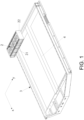
FIG. 1 is a schematic view of a battery device in a process of installing a first battery group according to an embodiment of the disclosure. -
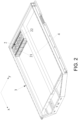
FIG. 2 is a schematic view of the battery device after the first battery group is installed in place according to an embodiment of the disclosure. -
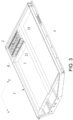
FIG. 3 is a schematic view of the battery device in a process of installing a first beam according to an embodiment of the disclosure. -
FIG. 4 is a schematic view of the battery device when the first beam is installed in place according to an embodiment of the disclosure. -
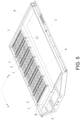
FIG. 5 is a schematic view of the battery device after a group of first beams and battery groups are assembled according to an embodiment of the disclosure. -
FIG. 6 is a schematic view of the battery device after a group of first beam and battery groups are assembled according to another embodiment of the disclosure. -
FIG. 7 is a flow chart of an assembling method of a battery device according to an embodiment of the disclosure. - The technical solutions in the exemplary embodiments of the disclosure will be described clearly and explicitly in conjunction with the drawings in the exemplary embodiments of the disclosure. The description proposed herein is just the exemplary embodiments for the purpose of illustrations only, not intended to limit the scope of the disclosure, so it should be understood that and various modifications and variations could be made thereto without departing from the scope of the disclosure.
- In the description of the present disclosure, unless otherwise specifically defined and limited, the terms "first", "second" and the like are only used for illustrative purposes and are not to be construed as expressing or implying a relative importance. The term "plurality" is two or more. The term "and/or" includes any and all combinations of one or more of the associated listed items.
- In particular, a reference to "the" object or "a" and "an" object is intended to denote also one of a possible plurality of such objects. Unless otherwise defined or described, the terms "connect", "fix" should be broadly interpreted, for example, the term "connect" can be "fixedly connect", "detachably connect", "integrally connect", "electrically connect" or "signal connect". The term "connect" also can be "directly connect" or "indirectly connect via a medium". For the persons skilled in the art, the specific meanings of the abovementioned terms in the present disclosure can be understood according to the specific situation.
- Further, in the description of the present disclosure, it should be understood that spatially relative terms, such as "above", "below" "inside", "outside" and the like, are described based on orientations illustrated in the figures, but are not intended to limit the exemplary embodiments of the present disclosure.
- In the context, it should also be understood that when an element or features is provided "outside" or "inside" of another element(s), it can be directly provided "outside" or "inside" of the other element, or be indirectly provided "outside" or "inside" of the another element(s) by an intermediate element.
- In the related art, a box of a battery pack is surrounded by beams to form a chamber, and battery groups are directly inserted into the chamber surrounded by the beams. In this arrangement, if the battery groups and the beams are not adhered to each other through adhesive, the battery groups may be easily displaced or may be easily separated from the chamber due to vibration and other reasons during the use of the battery pack, resulting in danger. Further, the vibration/impact force generated by the battery group may all act on a liquid-cooling plate located at the bottom. A slightly stronger impact force may easily cause the connection between the liquid-cooling plate and the beams to loosen or to be disconnected. The liquid-cooling plate may be damaged, and the liquid cooling plate may even leak. If an adhesive is applied onto the battery groups and/or the beams before the battery groups and/or the beams are placed into the chamber, the adhesive may be scratched off and adhered to other positions during the process of placing the battery group into the chamber. The amount of adhesive being actually applied is thereby reduced, and the adhesive is not being evenly applied, such that the batteries may not be stably fixed.
- In view of the above, the disclosure provides a battery device and an assembling method of the battery device, which can enhance the strength of adhering and fixing between beams and battery groups, such that the assembly yield of the battery groups is improved, and the overall yield of the battery device is increased.
- In the first aspect, the disclosure provides a battery device. As shown in
FIG. 1 ,FIG. 2 ,FIG. 3 ,FIG. 4 ,FIG. 5 , andFIG. 6 , the battery device includes abox frame 3,battery groups 2 andfirst beams 1 that are located in thebox frame 3. An Adhesive layer is provided between each of thefirst beams 1 and afirst side surface 21 of an adjacent one of thebattery groups 2, the adhesive layer is formed as each of thefirst beams 1 and thefirst side surface 21 of the adjacent one of thebattery groups 2 are mutually pressed in a first direction x. A side of one of thefirst beams 1 located at an end portion facing away from thebattery group 2 is adjacent to thebox frame 3 and is separated from thebox frame 3 by a first set interval s, and the first set interval s is configured to allow thefirst beam 1 at the end portion to move towards thefirst side surface 21 of thebattery group 2 for adhering. To be specific, thefirst beam 1 at the end portion is thefirst beam 1 provided with abattery group 2 on one side and not provided with abattery group 2 on the other side. In other words, one side of thefirst beam 1 at the end portion is configured for arranging abattery group 2, and the other side of thefirst beam 1 at the end portion is not configured for arranging abattery group 2, so thisfirst beam 1 at the end portion is only used to limit the position of abattery group 2 on one side. - In the battery device provided by this embodiment, the adhesive layers are provided between the
battery groups 2 and thefirst beams 1, and thebattery groups 2 and thefirst beams 1 are adhered and fixed to each other through the adhesive layers. In this way, the pressure generated by thebattery groups 2 on abottom plate 6 of a box may be reduced, and overall reliability and safety of the battery device may be improved. To be specific, thebattery groups 2 and thefirst beams 1 are arranged in sequence in the first direction x. The lastfirst beam 1 is located at an end portion in an arrangement direction of thebattery groups 2 and thefirst beams 1, and the lastfirst beam 1 is adjacent to thebox frame 3, and is separated from the close-bybox frame 3 by the first set interval s. This first set interval s provides a space for the installation operation of the lastfirst beam 1. Therefore, when the battery device is assembled, thebattery groups 2 and thefirst beams 1 may be installed in sequence, and thefirst beam 1 at the end portion is installed at last. In this way, the problem of the adhesive layers being scratched caused by insertion of thebattery groups 2 after formation of a chamber by the beam structure is prevented from occurring. To be specific, each of thefirst beams 1 may be moved towards and pressed against theadjacent battery group 2 in the first direction x during installation until a structural adhesive between thefirst side surface 21 of thebattery group 2 and thefirst beam 1 is squeezed apart, and installation is performed in place in this way. Therefore, in the installation process of thefirst beam 1, the adhesive layer is prevented from being scratched off, and the effect of the pressed adhesive overflow may also be achieved. The adhesive layer formed by pressing is uniform and dense and provides favorable adhesive strength after final coating and curing is performed, so that the adhesive strength between thefirst side surface 21 of thebattery group 2 and thefirst beam 1 is improved. In view of the above, in the battery device provided by the disclosure, the adhesive effect between thebattery groups 2 and the beams is improved and the assembly yield of the battery device is increased, and the battery device provided by the disclosure is thereby beneficial to industrial production. - In some embodiments, as shown in
FIG. 5 andFIG. 6 , in the battery device, thebattery groups 2 and thefirst beams 1 are arranged in sequence in an alternating manner, that is, arranged in a manner of the battery group 2 - first beam 1 - battery group 2 -first beam 1, in the first direction x. Therefore, when the battery device is assembled, thebattery groups 2 and thefirst beams 1 are installed in an alternating manner in sequence, and thefirst beam 1 at the end portion is installed last. - Certainly, in the first direction x, it may only provide one
battery group 2 and onefirst beam 1, and in this case, the onefirst beam 1 is the lastfirst beam 1, which is installed after thebattery group 2. - In some embodiments, as shown in
FIG. 5 andFIG. 6 , the first set interval s is greater than 5 mm. Preferably, the first set interval s is greater than 8 mm, for example, the first set interval s may be 8 mm, 10 mm, 12 mm, 14 mm, 16 mm, 18 mm, and 20 mm. Preferably, the first set interval s ranges between 8 mm and 15 mm. Through the arrangement of the first set interval s, a space that is sufficient for installation of the lastfirst beam 1 is kept. As such, the adhesive layer is prevented from being scratched off when thisfirst beam 1 is installed, so the assembly yield is ensured, a moving stroke of thisfirst beam 1 in the first direction x is shorter, and installation may thus be conveniently performed. Besides, the first set interval s does not occupy much space of the battery device, so that the energy density of the battery device is ensured. - Specifically, the
entire box frame 3 may be an integral structure or may be a structure that is spliced together by beams, frames, plates, and the like. In the disclosure, thebox frame 3 adjacent to the side of thefirst beam 1 at the end portion facing away from thebattery groups 2 may be a beam or a frame or other structures with substantially the same extending direction as thefirst beam 1. The first set interval s refers to a closest distance between a side surface of thefirst beam 1 facing away from thebattery group 2 and the beam or the frame. - In some embodiments, as shown in
FIG. 4 ,FIG. 5 , andFIG. 6 , thebox frame 3 includes asecond beam 4, and thesecond beam 4 intersects the extending direction of the first beams 1. To be specific, thefirst beams 1 are substantially perpendicular to the first direction x, thesecond beam 4 is substantially parallel to the first direction x, and thefirst beams 1 and thesecond beam 4 are detachably connected. - To be specific, the
second beam 4 may include either amiddle beam 41 that divides theentire box frame 3 into a plurality of chambers, and may include aside beam 42 that is adjacent to the frame of thebox frame 3. - The detachable connection between the
first beams 1 and thesecond beam 4 enables thefirst beams 1 and thebattery groups 2 to be installed in an alternating manner in sequence in turn, and enables thefirst beams 1 to be conveniently assembled and disassembled, and the reliability of the assembly of thefirst beams 1 is also ensured. - Exemplarily, both ends of each of the
first beams 1 respectively couple twosecond beams 4, and are respectively secured to the twosecond beams 4 by fasteners. To be specific, a height of each of thefirst beams 1 is greater than a height of each of thesecond beams 4, and both ends of each of thefirst beams 1 are respectively provided withcoupling portions 11 located above the second beams 4. Fasteners such as bolts 7 may be used to penetrate through thecoupling portions 11 and thesecond beams 4 in sequence, that is, end portions of thefirst beams 1 may be connected to the second beams 4. In this way, the fixing yield of thefirst beams 1 may be ensured. - Exemplarily, each
first beam 1 is provided with a first positioning portion, and eachsecond beam 4 is provided with a second positioning portion. The first positioning portion and the second positioning portion are matched, so that thefirst beam 1 and thesecond beam 4 are positioned and assembled. - To be specific, by arranging mutually matched positioning portions on the
first beams 1 and thesecond beams 4, the positioning of the assembly of thefirst beams 1 may be achieved, and the accuracy of the assembly positions of thefirst beams 1 may be improved. An excessively large or excessively small pressure applied on thebattery groups 2, due to the improper assembly of thefirst beams 1 and thereby affecting the assembly yield of the battery device, is thereby prevented from being generated. - For instance, the first positioning portions and the second positioning portions may be positioning holes, and the first positioning portions and the second positioning portions are aligned and matched and may be connected by fasteners such as bolts.
- Alternatively, the first positioning portions and the second positioning portions may also be the combination of bolts and positioning holes. For instance, the first positioning portions are positioning holes, and the second positioning portions are bolts fixed on the second beams 4. By placing the positioning holes on the bolts, the alignment and positioning of the
first beams 1 and thesecond beams 4 may be achieved, and the two may be fixed by locking of the nuts and bolts. Certainly, the first positioning portions and the second positioning portions in this embodiment are not limited to the abovementioned embodiment and may be arranged according to actual conditions. - In some embodiments, as shown in
FIG. 5 andFIG. 6 , thebox frame 3 includes abottom plate 6, and thefirst beams 1 and thebottom plate 6 are locked and fixed by fasteners such as bolts. - The
first beams 1 and thebottom plate 6 are detachably connected by fasteners such as bolts, and therefore, the fixing yield of thefirst beams 1 is further improved, thefirst beams 1 may be conveniently assembled and disassembled, and the reliability of the assembly of thefirst beams 1 is ensured. Further, by arranging installation holes on thefirst beams 1 and thesecond bottom plate 6, the assembly of thefirst beams 1 may be positioned, and the accuracy of the assembly positions of thefirst beams 1 may be improved. An excessively large or excessively small pressure applied on thebattery groups 2, due to the improper assembly of thefirst beams 1 and thereby affecting the assembly yield of the battery device, is thereby prevented from being generated. - In some embodiments, as shown in
FIG. 1 ,FIG. 2 ,FIG. 3 , andFIG. 4 , adhesive layers are respectively provided between two opposite second side surfaces 22 of thebattery group 2 and the adjacentsecond beams 4. - To be specific, the
battery group 2 is formed of at least one column of batteries, thebattery group 2 is substantially rectangular, and has six surfaces, specifically a top surface, a bottom surface, and four side surfaces. The four side surfaces include the two opposite first side surfaces 21 and the two opposite second side surfaces 22. In this embodiment, adhesive layers are provided on both the orientations of the two first side surfaces 21 and the two second side surfaces 22 of thebattery group 2. That is, the four side surfaces of thebattery group 2 and the corresponding beams are all fixed by adhesive layers. In this way, the pressure of thebattery group 2 on thebottom plate 6 may be further reduced, and the overall reliability and safety of the battery device may be further improved. - In some embodiments, as shown in
FIG. 1 ,FIG. 2 ,FIG. 3 , andFIG. 4 , thebattery group 2 includes at least one column of batteries, and an arrangement direction of each column of batteries is perpendicular to larger surfaces of the batteries. The larger surface of each battery is a surface with a largest area of the battery. Thefirst side surface 21 of thebattery group 2 is a side surface formed by the side surfaces of each column of batteries, which is parallel to the arrangement direction of each column of batteries. Correspondingly, thefirst beam 1 adhered to the firstlarger surface 21 is also parallel to the arrangement direction of each column of batteries. Thesecond side surface 22 of thebattery group 2 is formed by the larger surface of the end battery in each column of batteries. - To be specific, the two first side surfaces 21 of the
battery group 2 are substantially parallel to the arrangement direction of each column of batteries and include side surfaces of a plurality of batteries. The two second side surfaces 22 of thebattery group 2 are substantially perpendicular to the arrangement direction of each column of batteries and are formed by the larger surfaces of the end batteries in each column of batteries. When thebattery group 2 functions, the larger surfaces of the batteries may be easily bulged and deformed. That is, the deformation in the arrangement direction of each column of batteries is greater, which causes thebattery group 2 to be easily displaced in the direction perpendicular to the second side surfaces 22. Thefirst side surface 21 of thebattery group 2 is formed by the side surfaces of a plurality of batteries. When thebattery group 2 functions, the state of thefirst side surface 21 is relatively stable and is not prone to deformation and displacement. Therefore, relatively speaking, thefirst beam 1 opposite to thefirst side surface 21 of thebattery group 2 is more suitable for installation in the form of horizontal movement and pressing. - In this embodiment, the first side surfaces 21 of the
battery groups 2 face thefirst beams 1 and are adhered and fixed to thefirst beams 1, and thebattery groups 2 and thefirst beams 1 are installed in an alternating manner in the first direction x. During installation, eachfirst beam 1 is gradually moved towards thefirst side surface 21 of thebattery group 2 in the first direction x and is pressed. Therefore, the adhesive between the beam and thefirst side surface 21 of thebattery group 2 is pressed and overflows, so that the adhesive effect between thefirst side surface 21 of thebattery group 2 and thefirst beam 1 may be improved. - Besides, since it is difficult to control the pressing force of the
second side surface 22, thesecond beam 4 opposite to thesecond side surface 22 does not adopt the method of pressing and installing in sequence. To be specific, thesecond beam 4 may be pre-installed or integrally formed with thebox frame 3, and the position of thesecond beam 4 is precisely fixed. In this way, the problems of excessively large or excessively small pressing force and inaccurate assembly position when the moving and pressing installation method is adopted may be avoided, the safety performance and the overall assembly yield of the battery device is thereby ensured. - In some embodiments, as shown in
FIG. 1 ,FIG. 2 ,FIG. 3 ,FIG. 4 , andFIG. 5 , the battery device provided by this embodiment has a battery group region and a power distribution region. The battery group region is the region for assembling thebattery groups 2, and the power distribution region is the region for arrangement electrical devices. To be specific, thebox frame 3 includes adivider beam 5 that separates the battery group region from the power distribution region. Thedivider beam 5 is substantially perpendicular to the first direction x and is substantially arranged the same as the extending direction of the first beams 1. Thefirst beam 1 located at a rear end of the arrangement direction of thebattery groups 2 and thefirst beams 1 is adjacent to thedivider beam 5 and is separated from thedivider beam 5 by the first set interval s. - In other words, the side of the last-installed
first beam 1 facing away from thebattery group 2 is adjacent to thedivider beam 5 and is separated from thedivider beam 5 by the first set interval s. This first set interval s provides a space for the installation operation of the last-installedfirst beam 1. Therefore, when the lastfirst beam 1 is installed, the lastfirst beam 1 may first be disposed to be separated from theadjacent battery group 2 by a second set interval d in the first direction x. The second set interval d is less than or equal to the first set interval s. Next, the lastfirst beam 1 is moved towards itsadjacent battery group 2 and is pressed until the structural adhesive between thefirst side surface 21 of thebattery group 2 and thefirst beam 1 is squeezed apart. Installation is performed in place in this way, the adhesive layer is prevented from being scratched off, the effect of pressed adhesive overflow is achieved, and the adhesive strength between thefirst side surface 21 of thebattery group 2 and thefirst beam 1 is ensured. - In this embodiment, the
battery groups 2 and thefirst beams 1 are installed in an alternating manner from the battery group region to the power distribution region. First install thebattery group 2, thisbattery group 2 is adjacent to the frame of the box frame and is adhered to the frame of the box frame, and thefirst beam 1 is installed to press thebattery group 2, so that thefirst beam 1 and thebattery group 2 are adhered and fixed to each other. After that, in sequence, thebattery groups 2 and thefirst beams 1 are installed in an alternating manner until the lastfirst beam 1 is installed. The lastfirst beam 1 is adjacent to thedivider beam 5 and is separated from thedivider beam 5 by the first set interval s. In this embodiment, through the arrangement of the first set interval s, a distance between thebattery group 2 and an electrical device may be increased, and the probability of a short circuit between the two may be reduced. - In some embodiments, as shown in
FIG. 1 ,FIG. 2 ,FIG. 3 ,FIG. 4 , andFIG. 6 , the divider beam is not provided between the battery group region and the power distribution region. The battery group region is separated from the power distribution region by thefirst beam 1 located at the end portion. The side of thefirst beam 1 at the end portion facing away from thebattery group 2 is adjacent to the frame of thebox frame 3 and is separated from the frame by the first set interval s. - In this embodiment, the side of the last-installed
first beam 1 facing away from thebattery group 2 directly faces the frame of the box frame and is separated from the frame by the first set interval s. This first set interval s provides a space for the installation operation of the last-installedfirst beam 1, the adhesive layer is further prevented from being scratched during the installation of thefirst beam 1, and the adhesive is pressed and overflows through the installation of thefirst beam 1. As such, the adhesive strength between thefirst side surface 21 of thebattery group 2 and thefirst beam 1 is ensured. Besides, the region where the first set interval s is located is configured as the power distribution region. The power distribution region may be configured for arrangement of electrical devices after thefirst beams 1 are installed, and in this way, the space is reused and is effectively saved, and the energy density of the battery device is thereby improved. Further, the divider beam is omitted in this embodiment, so that a weight of the box frame may be reduced, the space may be saved, and the energy density of the battery device may be further improved. - To be specific, in actual operation, the solution of the disclosure is not limited to the assembling manner provided by the abovementioned embodiments. As long as it is ensured that the first set interval s is kept between the last-installed
first beam 1 and itsadjacent box frame 3, so as to ensure that thefirst beams 1 may move horizontally to implement the assembly operation. For instance, in some other embodiments, thebattery groups 2 and thefirst beams 1 may be arranged in an alternating manner in a second direction y. The second direction y is substantially perpendicular to the first direction x. Herein, thefirst beams 1 extend in the first direction x, and the side of the lastfirst beam 1 facing away from thebattery group 2 is adjacent to the box frame and is separated from the box frame by the first set interval s. - Further, in the disclosure, the
battery groups 2 and thefirst beams 1 that are arranged in an alternating manner in sequence in the first direction x are referred to as a group ofbattery groups 2 andfirst beams 1. As such, in the embodiments of the disclosure, in the box frame of the battery device, it may only provide one group ofbattery groups 2 andfirst beams 1 in an alternating manner in sequence in the first direction x, or it may also provide a plurality of groups of battery groups and first beams may be arranged in an alternating manner in sequence in the first direction x. Specific arrangement may be implemented according to actual conditions, which is not particularly limited by the disclosure. - In the second aspect, based on the same inventive concept as the battery device provided by the embodiments of the disclosure, the disclosure further provides an assembling method of a battery device. As shown in
FIG. 7 , the assembling method includes the following steps. - In the
step 101, as shown inFIG. 1 andFIG. 3 , a structural adhesive is arranged on thefirst side surface 21 of thebattery group 2 and/or on thefirst beam 1 adjacent to thefirst side surface 21. - In the
step 102, as shown inFIG. 1 ,FIG. 2 ,FIG. 3 ,FIG. 4 , andFIG. 5 , thebattery groups 2 and thefirst beams 1 are arranged in thebox frame 3 in sequence in the first direction x, and the side of thefirst beam 1 located at the end portion facing away from thebattery groups 2 is allowed to face thebox frame 3 and to be separated from thebox frame 3 by the first set interval s. - To be specific, the installation process of each of the
first beams 1 is provided as follows. With reference toFIG. 3 andFIG. 4 , thefirst beam 1 is arranged to be separated from theadjacent battery group 2 by the second set interval d in the first direction x. Thefirst beam 1 is then pressed towards theadjacent battery group 2 until the structural adhesive between thefirst side surface 21 of thebattery group 2 and thefirst beam 1 is squeezed apart, such that thebattery group 2 is firmly adhered to thefirst beam 1 by the structural adhesive. - In the assembling method of the battery device provided by this embodiment, the
battery groups 2 and thefirst beams 1 are installed in sequence. Eachfirst beam 1 is arranged to be separated from thefirst side surface 21 of thebattery group 2 by the second set interval d first during the installation process and then is moved towards thefirst side surface 21 of thebattery group 2 until it is assembled in place. Compared with the method of directly inserting thebattery groups 2 into the box chamber, in this installation method, the adhesive layer may be prevented from being scratched off, and the pressed adhesive overflow effect may also be achieved. As such, after the final coating and curing is performed, the adhesive layers may exhibit favorable adhesive strength, so that the adhesive strength between the first side surfaces 21 of thebattery groups 2 and thefirst beams 1 is improved, and the assembly yield of the battery device is increased, which is beneficial to industrial production. Besides, the last-installedfirst beam 1 is located at the rear end in the arrangement direction of thebattery groups 2 and thefirst beams 1, and the last-installed first beam lis adjacent to thebox frame 3, and is separated from the close-bybox frame 3 by the first set interval s. This first set interval s reserves a space for the installation operation of the lastfirst beam 1. Therefore, it is ensured that the lastfirst beam 1 may be moved horizontally so as to be assembled in place, the adhesive effect between thebattery groups 2 and thefirst beams 1 is improved, and the assembly yield of the battery device is increased. - It should be noted that, the coating process of the structural adhesives and the installation process of the battery groups and the first beams may be performed simultaneously, and specifically, an automated assembly operation may be performed through a processing assembly line. For instance, an adhesive may be applied to each battery group in sequence, and the battery groups are transferred to an assembly station, and the battery groups arriving at the assembly station may be installed into the box frame by a robotic arm. Similarly, the installation operation of the first beams may also be controlled by the robotic arm.
- In some embodiments, in the
step 102, thebattery groups 2 and thefirst beams 1 are installed in thebox frame 3 in sequence in the first direction x. To be specific, as shown inFIG. 5 andFIG. 6 , thebattery groups 2 and thefirst beams 1 are arranged in thebox frame 3 in sequence in an alternating manner, that is, arranged in a manner of the battery group 2 - first beam 1 - battery group 2 -first beam 1, in the first direction x. In this way, the adhesive layers between thebattery groups 2 and thefirst beams 1 are prevented from being scratched off, and the adhesive between eachfirst beam 1 and eachbattery group 2 is pressed and overflows, so that the assembly yield of the entire battery device is increased. - In some embodiments, the
battery groups 2 include at least one column of batteries, an arrangement direction of each of the at least one column of batteries is perpendicular to the larger surfaces of the batteries. In the assembling method of the battery device provided by the disclosure, the installation process of eachbattery group 2 includes the following step. Thebattery group 2 is over-pressed and loaded in the arrangement direction of each column of batteries into thebox frame 3. To be specific, the first side surfaces 21 of thebattery groups 2 are parallel to the arrangement direction of each column of batteries, each column of batteries in thebattery groups 2 are arranged in the second direction y, thebattery groups 2 and thefirst beams 1 are installed in an alternating manner in the first direction x, and the first direction x is substantially perpendicular to the second direction y. - When the
battery groups 2 function, the larger surfaces of the batteries may be easily bulged and deformed. That is, the deformation in the arrangement direction of each column of batteries is much more significant, which causes thebattery groups 2 to be easily displaced in the direction perpendicular to the second side surfaces 22, that is, the second direction y. Thefirst side surface 21 of eachbattery group 2 is formed by the side surfaces of a plurality of batteries. When thebattery group 2 functions, the state of thefirst side surface 21 is stable. That is, thebattery group 2 is not easily deformed and displaced in the direction perpendicular to thefirst side surface 21, that is, the first direction x. Therefore, relatively speaking, thefirst beams 1 opposite to the first side surfaces 21 of thebattery groups 2 are more suitable for installation in the form of horizontal movement and pressing. - In some embodiments, as shown in
FIG. 5 andFIG. 6 , thebox frame 3 includes thesecond beam 4, and thesecond beam 4 intersects the extending direction of the first beams 1. The assembling method of the battery device provided by this embodiment further includes the following step. - In the step, the
first beams 1 and thesecond beam 4 are locked and fixed by fasteners. For instance, the fasteners may be the bolts 7. - Exemplarily, both ends of each of the
first beams 1 respectively couple twosecond beams 4 and are respectively connected to the twosecond beams 4 by the bolts 7. To be specific, the height of each of thefirst beams 1 is greater than the height of each of thesecond beams 4, and both ends of each of thefirst beams 1 are provided with thecoupling portions 11 located above the second beams 4. Connectors such as the bolts 7 may be used to penetrate through thecoupling portions 11 and thesecond beams 4 in sequence, that is, the end portions of thefirst beams 1 may be connected to the second beams 4. - To be specific, the detachable connection between the
first beams 1 and thesecond beam 4 enables thefirst beams 1 and thebattery groups 2 to be installed in sequence in turn and to be conveniently assembled and disassembled, and the reliability of the assembly of thefirst beams 1 is also ensured. Further, by arranging the installation holes on thefirst beams 1 and thesecond beam 4, the assembly of thefirst beams 1 may be positioned, and the accuracy of the assembly positions of thefirst beams 1 may be improved. An excessively small pressure applied on thebattery groups 2, due to the improper assembly of thefirst beams 1 and thereby affecting the assembly yield of the battery device, is thereby prevented from being generated. - Exemplarily, the installation process of the
battery groups 2 and thefirst beams 1 and the locking and fixing process of thefirst beams 1 may be performed alternately. The specific operation may be provided as follows. A pair ofbattery group 2 and thefirst beam 1 are installed in thebox frame 3 in sequence, and thefirst beam 1 is secured to thesecond beam 4. Afterwards, another pair ofbattery group 2 and thefirst beam 1 are installed in thebox frame 3 in sequence, thefirst beam 1 is secured to thesecond beam 4, and so on, until the locking and fixing of the lastfirst beam 1 at the end portion is completed. In other words, after each pair ofbattery group 2 and thefirst beam 1 are assembled in place, thefirst beam 1 is locked and fixed immediately, and then the next pair ofbattery group 2 and thefirst beam 1 are assembled. Through this assembling method, it is beneficial to improve the installation and positioning effect of eachbattery group 2 and thefirst beam 1, and the assembly yield is also increased. Further, during the installation of each pair ofbattery group 2 and thefirst beam 1, the pressing force of thefirst beam 1 only acts on theadjacent battery group 2 and the previous one of the first beams 1. As such, it may be ensured that the force applied on each pair ofbattery group 2 and thefirst beam 1 is consistent, and the effect of the pressed adhesive overflow between thebattery group 2 and thefirst beam 1 is raised, and that the yield of adhesive fixing between eachbattery group 2 and thefirst beam 1 is increased. - In some embodiments, in the
step 102, the assembly process of thefirst beams 1 is specifically provided as follows. - As shown in
FIG. 5 andFIG. 6 , eachfirst beam 1 is pressed towards theadjacent battery group 2 until the structural adhesives on both sides of thebattery group 2 are squeezed apart, such that thebattery group 2 is firmly adhered to the structures at two sides of thebattery group 2 by the structural adhesives. In this way, through the assembly operation of eachfirst beam 1, the adhesive between thefirst beam 1 and itsadjacent battery group 2 is pressed and overflows, so thefirst beam 1 is adhered and fixed to itsadjacent battery group 2. Further, the adhesive between theadjacent battery group 2 and the previousfirst beam 1 or thefront box frame 3 may be pressed and overflows, so that theadjacent battery group 2 is adhered and fixed to the previousfirst beam 1 or thefront box frame 3. In this way, a simple operation is provided, the feasibility is high, and the adhering and fixing effect of thebattery groups 2 and thefirst beams 1 or thebox frame 3 may be improved. - In some embodiments, in the assembling method of the battery device provided by the disclosure, the
step 101 may further include the following step. As shown inFIG. 1 , the structural adhesives are arranged on the two opposite second side surfaces 22 of thebattery group 2 or on thesecond beam 4 adjacent to the second side surfaces 22. - In this embodiment, the structural adhesives are provided on both the orientations of the two first side surfaces 21 and the two second side surfaces 22 of the
battery group 2. That is, the four side surfaces of thebattery group 2 and the corresponding beams are all fixed by the adhesive layers. In this way, the pressure of thebattery group 2 on thebottom plate 6 may be further reduced, and the overall reliability and safety of the battery device may be further improved. - In some embodiments, as shown in
FIG. 5 , thebox frame 3 includes thebottom plate 6, and the assembling method of the battery device provided by this embodiment further includes the following step. - In the step, the
bottom plate 6 and thefirst beams 1 are locked and fixed by the bolts 7 and the like from a bottom portion of the battery device. - The
first beams 1 and thebottom plate 6 are detachably connected by connectors such as the bolts 7, and in this way, fixing yield of thefirst beams 1 is further increased, thefirst beams 1 may be conveniently assembled and disassembled, and the reliability of the assembly of thefirst beams 1 is ensured. Further, by arranging the installation holes on thefirst beams 1 and thesecond bottom plate 6, the assembly of thefirst beams 1 may be positioned, and the accuracy of the assembly positions of thefirst beams 1 may be improved. An excessively large or excessively small pressure applied on thebattery groups 2, due to the improper assembly of thefirst beams 1 and thereby affecting the assembly yield of the battery device, is thereby prevented from being generated. - In some embodiments, the
battery groups 2 and thefirst beams 1 are installed in thebox frame 3 in sequence in the first direction x, and this step specifically includes the following. - As shown in
FIG. 1 andFIG. 2 , the structural adhesive is arranged on the first-installed battery group and/or the frame of the box frame adjacent to the first-installed battery group, and the first-installed battery group is placed into the box frame adjacent to the frame of thebox frame 3. In other words, the position adjacent to the frame of the box frame is the starting position, and thebattery group 2 that is installed first is placed adjacent to the frame of the box and is adhered to the frame of the box. - In some embodiments, after the
step 102 is performed, the following step may further be included. - In the step, an electrical device is arranged at the first set interval s. In this way, the space in the
box frame 3 may be fully utilized, and the energy density of the battery device may be improved. - For instance, the side of the last-installed
first beam 1 facing away from thebattery group 2 directly faces the frame of the box and is separated from the frame by the first set interval s. The region where the first set interval s is located is configured as the power distribution region. The power distribution region may be configured for arrangement of the electrical device after thefirst beams 1 are installed, and in this way, the space is reused and is effectively saved, and the energy density of the battery device is thereby improved. - In some embodiments, as shown in
FIG. 5 andFIG. 6 , the first set interval s is greater than 5 mm. Preferably, the first set interval s is greater than 8 mm, for example, the first set interval s may be 8 mm, 10 mm, 12 mm, 14 mm, 16 mm, 18 mm, and 20 mm. Preferably, the first set interval s is between 8 mm and 15 mm. Through the arrangement of the first set interval s, a space that is sufficient for installation of the lastfirst beam 1 is kept. As such, the adhesive layer is prevented from being scratched off when thisfirst beam 1 is installed, so the assembly yield is ensured, the moving stroke of thisfirst beam 1 in the first direction x is short, and installation may thus be conveniently performed. Besides, the first set interval s does not occupy much space of the battery device, so that the energy density of the battery device is ensured. - In some embodiments, as shown in
FIG. 3 , the second set interval d is greater than 5 mm. In thestep 102, arranging thefirst beam 1 to be separated from theadjacent battery group 2 by the second set interval d in the first direction x further includes the following step. To be specific, thefirst beam 1 is arranged at a distance of greater than 5 mm from thebattery group 2, preferably at a distance of 8 mm to 15 mm, for example, the distance may specifically be 8 mm, 10 mm, 12 mm, 14 mm, and 15 mm. - Through the arrangement of the second set interval d, the adhesive layer between the
first beam 1 and thebattery group 2 is prevented from being scratched off. As such, the assembly yield is ensured, the moving stroke of thefirst beam 1 in the first direction x is shorter, and installation may be conveniently performed. - To be specific, as shown in
FIG. 3 andFIG. 5 , the specific values of the second set interval d between the differentfirst beams 1 and theadjacent battery groups 2 may be different during the installation process. For instance, regarding the last-installedfirst beam 1, the second set interval d between thisfirst beam 1 and itsadjacent battery group 2 during the installation process is required to be less than or equal to the first set interval s. Regarding the rest of thefirst beams 1, the second set interval d between each of thesefirst beams 1 and itsadjacent battery group 2 during the installation process may be greater than the first set interval s. - In the assembling method of the battery device provided by this embodiment, the battery groups and the first beams are assembled in an alternating manner. Further, the first beams are adhered and fixed to the battery groups by moving the first beams horizontally until the battery groups are pressed. In this way, the adhesive fixing strength between the first beams and the battery groups may be enhanced, and adhesive scratching caused by direct installation of the battery groups in the chamber of the box is also prevented from occurring. As such, the assembly yield of the battery device is increased, the feasibility of the process is improved through the assembling method, and the production efficiency is raised.
- To be specific, the assembling method of the battery device provided by the disclosure have the same inventive concept as the battery device provided by the disclosure and have the same embodiments and beneficial effects, and description thereof is not repeated herein in the disclosure.
- To be specific, the battery device provided by this embodiment may be a battery pack. The bottom plate of the battery device may include a liquid cooling plate. The battery groups and the beams are fixed by adhesives, and in this way, the pressure of the battery groups on the liquid cooling plate may be reduced, and the safety and reliability of the battery pack is improved.
- Other embodiments of the disclosure will be apparent to those skilled in the art from consideration of the specification and practice of the disclosure disclosed herein. The disclosure is intended to cover any variations, uses or adaptations of the disclosure. These variations, uses, or adaptations follow the general principles of the disclosure and include common general knowledge or conventional technical means in the art that are not disclosed in the present disclosure. The specification and embodiments are illustrative.
Claims (23)
- A battery device, comprising a box frame (3), and battery groups (2) and first beams (1) located in the box frame (3), wherein an adhesive layer is provided between each of the first beams (1) and a first side surface (21) of an adjacent one of the battery groups (2), the adhesive layer is formed as each of the first beams (1) and the first side surface (21) of the adjacent one of the battery groups (2) are mutually pressed in a first direction (x), a side of one of the first beams (1) located at an end portion facing away from the battery groups (2) is adjacent to the box frame (3) and is separated from the box frame (3) by a first set interval (s), and the first set interval (s) is configured to allow the first beam (1) at the end portion to move towards the first side surface (21) of the battery group (2) for adhering.
- The battery device according to claim 1, wherein the battery groups (2) and the first beams (1) are arranged in an alternating manner in sequence in the first direction (x).
- The battery device according to claim 1, wherein the first set interval (s) is greater than 5 mm.
- The battery device according to claim 1, wherein each of the battery groups (2) comprises at least one column of batteries, an arrangement direction of the at least one column of batteries is perpendicular to larger surfaces of the batteries, and the first beams (1) are parallel to the arrangement direction of the at least one column of batteries.
- The battery device according to claim 1, wherein the box frame (3) comprises a second beam (4), the second beam (4) intersects an extending direction of the first beams (1), and the first beams (1) and the second beams (4) are detachably connected.
- The battery device according to claim 5, wherein both ends of each of the first beams respectively couple two second beams (4), and are respectively secured to the two second beams (4) by fasteners (7).
- The battery device according to claim 5, wherein each of the first beams (1) is provided with a first positioning portion, the second beam (4) is provided with a second positioning portion, and the first positioning portion and the second positioning portion are matched, such that the first beams (1) and the second beam (4) are positioned and assembled.
- The battery device according to claim 7, wherein the first positioning portion and the second positioning portion are positioning holes, and the first positioning portion and the second positioning portion are connected by a fastener (7).
- The battery device according to claim 5, wherein an adhesive layer is provided between the second beam (4) and a second side surface (22) of the adjacent one of the battery groups (2).
- The battery device according to claim 1, wherein the box frame (3) further comprises a bottom plate (6), and the first beams (1) and the bottom plate (6) are connected by fasteners.
- The battery device according to any one of claims 1-10, wherein the battery device has a battery group region and a power distribution region, the box frame (3) comprises a divider beam (5) separating the battery group region from the power distribution region, and the side of the first beam (1) located at the end portion facing away from the battery group (2) is adjacent to the divider beam (5) and is separated from the divider beam (5) by the first set interval (s).
- The battery device according to any one of claims 1-10, wherein the battery device has a battery group region and a power distribution region, the first beam (1) at the end portion separates the battery group region from the power distribution region, and the side of the first beam (1) located at the end portion facing away from the battery group (2) is adjacent to a frame of the box frame (3) and is separated from the frame by the first set interval (s).
- An assembling method of a battery device, comprising the following steps:arranging a structural adhesive on a first side surface (21) of each battery group (2) and/or on a first beams (1) adjacent to the first side surface (21); andinstalling the battery groups (2) and the first beams (1) in a box frame (3) in sequence in a first direction (x), and allowing a side of one of the first beams (1) located at an end portion facing away from the battery groups (2) to face the box frame (3) and to be separated from the box frame (3) by a first set interval (s), wherein an installation process of each first beam (1) includes:
arranging the first beam (1) to be separated from the adjacent battery group (2) by a second set interval (d) in the first direction (x), and then pressing the first beam (1) towards the adjacent battery group (2) until the structural adhesive between the first side surface (21) of the battery group (2) and the first beam (1) is squeezed apart, such that the battery group (2) is firmly adhered to the first beam (1) by the structural adhesive. - The assembling method of the battery device according to claim 13, wherein the step of installing the battery groups (2) and the first beams (1) in the box frame (3) in sequence in the first direction (x) further comprises: installing the battery groups (2) and the first beams (1) in the box frame (3) in an alternating manner in sequence in the first direction (x).
- The assembling method of the battery device according to claim 13, wherein the first set interval (s) is greater than 5 mm.
- The assembling method of the battery device according to claim 13, wherein each of the battery groups (2) comprises at least one column of batteries, an arrangement direction of the at least one column of batteries is perpendicular to larger surfaces of the batteries, and an installation process of each battery group (2) comprises:
over-pressing and loading the battery group (2) in the arrangement direction of the at least one column of batteries into the box frame (3), wherein the first side surface (21) of the battery group (2) is parallel to the arrangement direction of the at least one column of batteries. - The assembling method of the battery device according to claim 13, wherein the box frame (3) comprises second beams (4), the second beams (4) intersect an extending direction of the first beams (1), and the assembling method of the battery device further comprises:
securing the first beams (1) and the second beam (4) by fasteners (7). - The assembling method of the battery device according to claim 17, further comprising: arranging structural adhesives on two opposite second side surfaces (22) of each battery group (2) or on the second beams (4) adjacent to the second side surfaces (22).
- The assembling method of the battery device according to claim 13, wherein the box frame (3) comprises a bottom plate (6), and the assembling method of the battery device further comprises:
securing the bottom plate (6) and the first beams (1) by fasteners from a bottom portion of the battery device. - The assembling method of the battery device according to claim 13, wherein the step of arranging the first beam (1) to be separated from the adjacent battery group (2) by the second set interval (d) in the first direction (x) further comprises:
arranging the first beam (1) to be separated from the adjacent battery group (2) by 8 mm to 15 mm. - The assembling method of the battery device according to claim 13, wherein the step of installing the battery groups (2) and the first beams (1) in the box frame (3) in sequence in the first direction (x) further comprises:
arranging the structural adhesive on the first-installed battery group (2) and/or a frame of the box frame (3) adjacent to the first-installed battery group (2) and placing the first-installed battery group (2) into the box frame (3) and adjacent to the frame of the box frame (3). - The assembling method of the battery device according to claim 13, wherein the step of pressing the first beam (1) towards the adjacent battery group (2) until the structural adhesive between the first side surface (21) of the battery group (2) and the first beam (1) is squeezed apart, such that the battery group (2) is firmly adhered to the first beam (1) by the structural adhesive further comprises:
pressing the first beam (1) towards the adjacent battery group (2) until the structural adhesives on two sides of the battery group (2) are squeezed apart, such that the battery group (2) is firmly adhered to the structures at the two sides of the battery group (2) by the structural adhesives. - The assembling method of the battery device according to any one of claims 13-22, wherein after the step of installing the battery groups (2) and the first beams (1) in the box frame (3) in sequence in the first direction (x), further comprises:
arranging an electrical device at the first set interval (s).
Applications Claiming Priority (1)
| Application Number | Priority Date | Filing Date | Title |
|---|---|---|---|
| CN202210235154.3A CN114335862B (en) | 2022-03-11 | 2022-03-11 | Battery device and battery device assembly method |
Publications (2)
| Publication Number | Publication Date |
|---|---|
| EP4243162A1 true EP4243162A1 (en) | 2023-09-13 |
| EP4243162B1 EP4243162B1 (en) | 2024-04-10 |
Family
ID=81033606
Family Applications (1)
| Application Number | Title | Priority Date | Filing Date |
|---|---|---|---|
| EP22194295.6A Active EP4243162B1 (en) | 2022-03-11 | 2022-09-07 | Battery device and assembling method of battery device |
Country Status (3)
| Country | Link |
|---|---|
| US (1) | US20230291056A1 (en) |
| EP (1) | EP4243162B1 (en) |
| CN (1) | CN114335862B (en) |
Families Citing this family (8)
| Publication number | Priority date | Publication date | Assignee | Title |
|---|---|---|---|---|
| CN114725606A (en) * | 2022-04-14 | 2022-07-08 | 中创新航科技股份有限公司 | Terminal insulating plate, battery device, and method for assembling battery device |
| CN114843693A (en) * | 2022-07-01 | 2022-08-02 | 中创新航科技股份有限公司 | Battery box and battery package |
| CN117673605A (en) * | 2022-08-24 | 2024-03-08 | 优跑汽车技术(上海)有限公司 | A connection structure and connection method between a battery module and a box |
| WO2024044970A1 (en) * | 2022-08-30 | 2024-03-07 | 宁德时代新能源科技股份有限公司 | Box, battery and electric device |
| CN115498349B (en) * | 2022-11-18 | 2023-03-28 | 中创新航科技股份有限公司 | Collinear assembly method and collinear assembly equipment for battery device and battery device |
| CN117154324B (en) * | 2023-10-30 | 2024-04-05 | 宁德时代新能源科技股份有限公司 | Battery and electricity utilization device |
| CN222394967U (en) * | 2024-04-23 | 2025-01-24 | 惠州亿纬锂能股份有限公司 | Battery pack and electronic equipment |
| CN221614109U (en) * | 2024-06-07 | 2024-08-27 | 宁德时代新能源科技股份有限公司 | Battery, power consumption device and vehicle |
Citations (3)
| Publication number | Priority date | Publication date | Assignee | Title |
|---|---|---|---|---|
| DE102018214889A1 (en) * | 2018-08-31 | 2020-03-05 | Bayerische Motoren Werke Aktiengesellschaft | Motor vehicle battery |
| CN215680823U (en) * | 2021-09-15 | 2022-01-28 | 东软睿驰汽车技术(沈阳)有限公司 | Battery pack and vehicle |
| CN215955398U (en) * | 2021-08-13 | 2022-03-04 | 中航锂电科技有限公司 | Battery pack |
Family Cites Families (6)
| Publication number | Priority date | Publication date | Assignee | Title |
|---|---|---|---|---|
| CN111312956B (en) * | 2020-02-27 | 2022-10-11 | 爱驰汽车有限公司 | Battery pack, battery pack manufacturing device, and battery pack manufacturing method |
| CN212500789U (en) * | 2020-04-20 | 2021-02-09 | 安徽易合新能源科技有限公司 | Square electricity core bicycle power battery module erects dress structure |
| CN111446397A (en) * | 2020-04-26 | 2020-07-24 | 天津市捷威动力工业有限公司 | Battery pack box and battery pack |
| CN112259856A (en) * | 2020-09-30 | 2021-01-22 | 远景动力技术(江苏)有限公司 | Battery pack |
| CN113363645B (en) * | 2021-05-18 | 2023-01-17 | 中国第一汽车股份有限公司 | Quick-change power battery assembly capable of delaying thermal diffusion and electric vehicle |
| CN215342761U (en) * | 2021-06-09 | 2021-12-28 | 泰州南洋塑料制品有限公司 | Low-temperature-resistant storage battery cover with adjustable structure |
-
2022
- 2022-03-11 CN CN202210235154.3A patent/CN114335862B/en active Active
- 2022-09-05 US US17/902,905 patent/US20230291056A1/en not_active Abandoned
- 2022-09-07 EP EP22194295.6A patent/EP4243162B1/en active Active
Patent Citations (3)
| Publication number | Priority date | Publication date | Assignee | Title |
|---|---|---|---|---|
| DE102018214889A1 (en) * | 2018-08-31 | 2020-03-05 | Bayerische Motoren Werke Aktiengesellschaft | Motor vehicle battery |
| CN215955398U (en) * | 2021-08-13 | 2022-03-04 | 中航锂电科技有限公司 | Battery pack |
| CN215680823U (en) * | 2021-09-15 | 2022-01-28 | 东软睿驰汽车技术(沈阳)有限公司 | Battery pack and vehicle |
Also Published As
| Publication number | Publication date |
|---|---|
| CN114335862B (en) | 2022-05-17 |
| EP4243162B1 (en) | 2024-04-10 |
| CN114335862A (en) | 2022-04-12 |
| US20230291056A1 (en) | 2023-09-14 |
Similar Documents
| Publication | Publication Date | Title |
|---|---|---|
| EP4243162A1 (en) | Battery device and assembling method of battery device | |
| EP3905371B1 (en) | Battery box and battery module | |
| US11302986B2 (en) | Battery module, battery pack, and vehicle | |
| EP2808922A1 (en) | Battery module | |
| US20250007073A1 (en) | Battery module unit, battery module, energy storage system, and electric vehicle | |
| US20230322065A1 (en) | Battery device, assembling method and assembling equipment thereof, and battery component positioning tooling | |
| KR20240140885A (en) | Battery assembly and assembly method thereof | |
| JP2023528973A (en) | battery pack and vehicle | |
| CN115995651B (en) | Battery pack and electricity utilization device | |
| CN114571194A (en) | Method and tool for machining whole hole positions of battery tray of new energy automobile | |
| US20230335844A1 (en) | End insulating plate, battery device, and assembly method of battery device | |
| US10944141B2 (en) | Composite end plate and battery module | |
| CN220155705U (en) | Conductive sheet, busbar bracket, busbar mounting structure, battery module and battery | |
| CN112355940A (en) | Carrier tool | |
| CN219801140U (en) | CTP battery mounting structure and battery pack | |
| CN217334318U (en) | Battery device | |
| CN217405578U (en) | Battery module | |
| CN118801021A (en) | Battery, power-consuming device, and battery assembly method | |
| CN220628102U (en) | Battery box | |
| CN113471596A (en) | Manufacturing method for battery and battery | |
| CN220162259U (en) | Cell module clamping device and discharging equipment | |
| EP4651269A1 (en) | Battery pack and vehicle | |
| CN223039059U (en) | A battery module and a battery pack | |
| CN223527278U (en) | A battery device and a vehicle | |
| CN222813747U (en) | Compacting and shaping device |
Legal Events
| Date | Code | Title | Description |
|---|---|---|---|
| PUAI | Public reference made under article 153(3) epc to a published international application that has entered the european phase |
Free format text: ORIGINAL CODE: 0009012 |
|
| STAA | Information on the status of an ep patent application or granted ep patent |
Free format text: STATUS: REQUEST FOR EXAMINATION WAS MADE |
|
| 17P | Request for examination filed |
Effective date: 20220907 |
|
| AK | Designated contracting states |
Kind code of ref document: A1 Designated state(s): AL AT BE BG CH CY CZ DE DK EE ES FI FR GB GR HR HU IE IS IT LI LT LU LV MC MK MT NL NO PL PT RO RS SE SI SK SM TR |
|
| GRAP | Despatch of communication of intention to grant a patent |
Free format text: ORIGINAL CODE: EPIDOSNIGR1 |
|
| STAA | Information on the status of an ep patent application or granted ep patent |
Free format text: STATUS: GRANT OF PATENT IS INTENDED |
|
| RIC1 | Information provided on ipc code assigned before grant |
Ipc: B60L 50/64 20190101ALI20231215BHEP Ipc: H01M 50/289 20210101ALI20231215BHEP Ipc: H01M 50/262 20210101ALI20231215BHEP Ipc: H01M 50/244 20210101ALI20231215BHEP Ipc: H01M 50/209 20210101ALI20231215BHEP Ipc: H01M 50/202 20210101ALI20231215BHEP Ipc: H01M 50/103 20210101AFI20231215BHEP |
|
| INTG | Intention to grant announced |
Effective date: 20240111 |
|
| GRAS | Grant fee paid |
Free format text: ORIGINAL CODE: EPIDOSNIGR3 |
|
| GRAA | (expected) grant |
Free format text: ORIGINAL CODE: 0009210 |
|
| STAA | Information on the status of an ep patent application or granted ep patent |
Free format text: STATUS: THE PATENT HAS BEEN GRANTED |
|
| AK | Designated contracting states |
Kind code of ref document: B1 Designated state(s): AL AT BE BG CH CY CZ DE DK EE ES FI FR GB GR HR HU IE IS IT LI LT LU LV MC MK MT NL NO PL PT RO RS SE SI SK SM TR |
|
| REG | Reference to a national code |
Ref country code: GB Ref legal event code: FG4D |
|
| REG | Reference to a national code |
Ref country code: CH Ref legal event code: EP |
|
| REG | Reference to a national code |
Ref country code: DE Ref legal event code: R096 Ref document number: 602022002809 Country of ref document: DE |
|
| REG | Reference to a national code |
Ref country code: IE Ref legal event code: FG4D |
|
| REG | Reference to a national code |
Ref country code: LT Ref legal event code: MG9D |
|
| REG | Reference to a national code |
Ref country code: NL Ref legal event code: MP Effective date: 20240410 |
|
| REG | Reference to a national code |
Ref country code: AT Ref legal event code: MK05 Ref document number: 1675872 Country of ref document: AT Kind code of ref document: T Effective date: 20240410 |
|
| PG25 | Lapsed in a contracting state [announced via postgrant information from national office to epo] |
Ref country code: NL Free format text: LAPSE BECAUSE OF FAILURE TO SUBMIT A TRANSLATION OF THE DESCRIPTION OR TO PAY THE FEE WITHIN THE PRESCRIBED TIME-LIMIT Effective date: 20240410 |
|
| PG25 | Lapsed in a contracting state [announced via postgrant information from national office to epo] |
Ref country code: NL Free format text: LAPSE BECAUSE OF FAILURE TO SUBMIT A TRANSLATION OF THE DESCRIPTION OR TO PAY THE FEE WITHIN THE PRESCRIBED TIME-LIMIT Effective date: 20240410 |
|
| PG25 | Lapsed in a contracting state [announced via postgrant information from national office to epo] |
Ref country code: IS Free format text: LAPSE BECAUSE OF FAILURE TO SUBMIT A TRANSLATION OF THE DESCRIPTION OR TO PAY THE FEE WITHIN THE PRESCRIBED TIME-LIMIT Effective date: 20240810 |
|
| PG25 | Lapsed in a contracting state [announced via postgrant information from national office to epo] |
Ref country code: BG Free format text: LAPSE BECAUSE OF FAILURE TO SUBMIT A TRANSLATION OF THE DESCRIPTION OR TO PAY THE FEE WITHIN THE PRESCRIBED TIME-LIMIT Effective date: 20240410 |
|
| PG25 | Lapsed in a contracting state [announced via postgrant information from national office to epo] |
Ref country code: FI Free format text: LAPSE BECAUSE OF FAILURE TO SUBMIT A TRANSLATION OF THE DESCRIPTION OR TO PAY THE FEE WITHIN THE PRESCRIBED TIME-LIMIT Effective date: 20240410 Ref country code: HR Free format text: LAPSE BECAUSE OF FAILURE TO SUBMIT A TRANSLATION OF THE DESCRIPTION OR TO PAY THE FEE WITHIN THE PRESCRIBED TIME-LIMIT Effective date: 20240410 |
|
| PG25 | Lapsed in a contracting state [announced via postgrant information from national office to epo] |
Ref country code: GR Free format text: LAPSE BECAUSE OF FAILURE TO SUBMIT A TRANSLATION OF THE DESCRIPTION OR TO PAY THE FEE WITHIN THE PRESCRIBED TIME-LIMIT Effective date: 20240711 |
|
| PG25 | Lapsed in a contracting state [announced via postgrant information from national office to epo] |
Ref country code: PT Free format text: LAPSE BECAUSE OF FAILURE TO SUBMIT A TRANSLATION OF THE DESCRIPTION OR TO PAY THE FEE WITHIN THE PRESCRIBED TIME-LIMIT Effective date: 20240812 |
|
| PG25 | Lapsed in a contracting state [announced via postgrant information from national office to epo] |
Ref country code: ES Free format text: LAPSE BECAUSE OF FAILURE TO SUBMIT A TRANSLATION OF THE DESCRIPTION OR TO PAY THE FEE WITHIN THE PRESCRIBED TIME-LIMIT Effective date: 20240410 |
|
| PG25 | Lapsed in a contracting state [announced via postgrant information from national office to epo] |
Ref country code: AT Free format text: LAPSE BECAUSE OF FAILURE TO SUBMIT A TRANSLATION OF THE DESCRIPTION OR TO PAY THE FEE WITHIN THE PRESCRIBED TIME-LIMIT Effective date: 20240410 |
|
| PG25 | Lapsed in a contracting state [announced via postgrant information from national office to epo] |
Ref country code: PL Free format text: LAPSE BECAUSE OF FAILURE TO SUBMIT A TRANSLATION OF THE DESCRIPTION OR TO PAY THE FEE WITHIN THE PRESCRIBED TIME-LIMIT Effective date: 20240410 |
|
| PG25 | Lapsed in a contracting state [announced via postgrant information from national office to epo] |
Ref country code: LV Free format text: LAPSE BECAUSE OF FAILURE TO SUBMIT A TRANSLATION OF THE DESCRIPTION OR TO PAY THE FEE WITHIN THE PRESCRIBED TIME-LIMIT Effective date: 20240410 |
|
| PG25 | Lapsed in a contracting state [announced via postgrant information from national office to epo] |
Ref country code: PT Free format text: LAPSE BECAUSE OF FAILURE TO SUBMIT A TRANSLATION OF THE DESCRIPTION OR TO PAY THE FEE WITHIN THE PRESCRIBED TIME-LIMIT Effective date: 20240812 Ref country code: PL Free format text: LAPSE BECAUSE OF FAILURE TO SUBMIT A TRANSLATION OF THE DESCRIPTION OR TO PAY THE FEE WITHIN THE PRESCRIBED TIME-LIMIT Effective date: 20240410 Ref country code: NO Free format text: LAPSE BECAUSE OF FAILURE TO SUBMIT A TRANSLATION OF THE DESCRIPTION OR TO PAY THE FEE WITHIN THE PRESCRIBED TIME-LIMIT Effective date: 20240710 Ref country code: LV Free format text: LAPSE BECAUSE OF FAILURE TO SUBMIT A TRANSLATION OF THE DESCRIPTION OR TO PAY THE FEE WITHIN THE PRESCRIBED TIME-LIMIT Effective date: 20240410 Ref country code: IS Free format text: LAPSE BECAUSE OF FAILURE TO SUBMIT A TRANSLATION OF THE DESCRIPTION OR TO PAY THE FEE WITHIN THE PRESCRIBED TIME-LIMIT Effective date: 20240810 Ref country code: HR Free format text: LAPSE BECAUSE OF FAILURE TO SUBMIT A TRANSLATION OF THE DESCRIPTION OR TO PAY THE FEE WITHIN THE PRESCRIBED TIME-LIMIT Effective date: 20240410 Ref country code: GR Free format text: LAPSE BECAUSE OF FAILURE TO SUBMIT A TRANSLATION OF THE DESCRIPTION OR TO PAY THE FEE WITHIN THE PRESCRIBED TIME-LIMIT Effective date: 20240711 Ref country code: FI Free format text: LAPSE BECAUSE OF FAILURE TO SUBMIT A TRANSLATION OF THE DESCRIPTION OR TO PAY THE FEE WITHIN THE PRESCRIBED TIME-LIMIT Effective date: 20240410 Ref country code: ES Free format text: LAPSE BECAUSE OF FAILURE TO SUBMIT A TRANSLATION OF THE DESCRIPTION OR TO PAY THE FEE WITHIN THE PRESCRIBED TIME-LIMIT Effective date: 20240410 Ref country code: BG Free format text: LAPSE BECAUSE OF FAILURE TO SUBMIT A TRANSLATION OF THE DESCRIPTION OR TO PAY THE FEE WITHIN THE PRESCRIBED TIME-LIMIT Effective date: 20240410 Ref country code: AT Free format text: LAPSE BECAUSE OF FAILURE TO SUBMIT A TRANSLATION OF THE DESCRIPTION OR TO PAY THE FEE WITHIN THE PRESCRIBED TIME-LIMIT Effective date: 20240410 Ref country code: RS Free format text: LAPSE BECAUSE OF FAILURE TO SUBMIT A TRANSLATION OF THE DESCRIPTION OR TO PAY THE FEE WITHIN THE PRESCRIBED TIME-LIMIT Effective date: 20240710 |
|
| REG | Reference to a national code |
Ref country code: DE Ref legal event code: R097 Ref document number: 602022002809 Country of ref document: DE |
|
| PG25 | Lapsed in a contracting state [announced via postgrant information from national office to epo] |
Ref country code: DK Free format text: LAPSE BECAUSE OF FAILURE TO SUBMIT A TRANSLATION OF THE DESCRIPTION OR TO PAY THE FEE WITHIN THE PRESCRIBED TIME-LIMIT Effective date: 20240410 |
|
| PG25 | Lapsed in a contracting state [announced via postgrant information from national office to epo] |
Ref country code: EE Free format text: LAPSE BECAUSE OF FAILURE TO SUBMIT A TRANSLATION OF THE DESCRIPTION OR TO PAY THE FEE WITHIN THE PRESCRIBED TIME-LIMIT Effective date: 20240410 |
|
| PG25 | Lapsed in a contracting state [announced via postgrant information from national office to epo] |
Ref country code: CZ Free format text: LAPSE BECAUSE OF FAILURE TO SUBMIT A TRANSLATION OF THE DESCRIPTION OR TO PAY THE FEE WITHIN THE PRESCRIBED TIME-LIMIT Effective date: 20240410 |
|
| PG25 | Lapsed in a contracting state [announced via postgrant information from national office to epo] |
Ref country code: RO Free format text: LAPSE BECAUSE OF FAILURE TO SUBMIT A TRANSLATION OF THE DESCRIPTION OR TO PAY THE FEE WITHIN THE PRESCRIBED TIME-LIMIT Effective date: 20240410 Ref country code: SK Free format text: LAPSE BECAUSE OF FAILURE TO SUBMIT A TRANSLATION OF THE DESCRIPTION OR TO PAY THE FEE WITHIN THE PRESCRIBED TIME-LIMIT Effective date: 20240410 |
|
| PG25 | Lapsed in a contracting state [announced via postgrant information from national office to epo] |
Ref country code: SM Free format text: LAPSE BECAUSE OF FAILURE TO SUBMIT A TRANSLATION OF THE DESCRIPTION OR TO PAY THE FEE WITHIN THE PRESCRIBED TIME-LIMIT Effective date: 20240410 |
|
| PG25 | Lapsed in a contracting state [announced via postgrant information from national office to epo] |
Ref country code: SM Free format text: LAPSE BECAUSE OF FAILURE TO SUBMIT A TRANSLATION OF THE DESCRIPTION OR TO PAY THE FEE WITHIN THE PRESCRIBED TIME-LIMIT Effective date: 20240410 Ref country code: SK Free format text: LAPSE BECAUSE OF FAILURE TO SUBMIT A TRANSLATION OF THE DESCRIPTION OR TO PAY THE FEE WITHIN THE PRESCRIBED TIME-LIMIT Effective date: 20240410 Ref country code: RO Free format text: LAPSE BECAUSE OF FAILURE TO SUBMIT A TRANSLATION OF THE DESCRIPTION OR TO PAY THE FEE WITHIN THE PRESCRIBED TIME-LIMIT Effective date: 20240410 Ref country code: EE Free format text: LAPSE BECAUSE OF FAILURE TO SUBMIT A TRANSLATION OF THE DESCRIPTION OR TO PAY THE FEE WITHIN THE PRESCRIBED TIME-LIMIT Effective date: 20240410 Ref country code: DK Free format text: LAPSE BECAUSE OF FAILURE TO SUBMIT A TRANSLATION OF THE DESCRIPTION OR TO PAY THE FEE WITHIN THE PRESCRIBED TIME-LIMIT Effective date: 20240410 Ref country code: CZ Free format text: LAPSE BECAUSE OF FAILURE TO SUBMIT A TRANSLATION OF THE DESCRIPTION OR TO PAY THE FEE WITHIN THE PRESCRIBED TIME-LIMIT Effective date: 20240410 |
|
| PG25 | Lapsed in a contracting state [announced via postgrant information from national office to epo] |
Ref country code: IT Free format text: LAPSE BECAUSE OF FAILURE TO SUBMIT A TRANSLATION OF THE DESCRIPTION OR TO PAY THE FEE WITHIN THE PRESCRIBED TIME-LIMIT Effective date: 20240410 |
|
| PLBE | No opposition filed within time limit |
Free format text: ORIGINAL CODE: 0009261 |
|
| STAA | Information on the status of an ep patent application or granted ep patent |
Free format text: STATUS: NO OPPOSITION FILED WITHIN TIME LIMIT |
|
| 26N | No opposition filed |
Effective date: 20250113 |
|
| PG25 | Lapsed in a contracting state [announced via postgrant information from national office to epo] |
Ref country code: SI Free format text: LAPSE BECAUSE OF FAILURE TO SUBMIT A TRANSLATION OF THE DESCRIPTION OR TO PAY THE FEE WITHIN THE PRESCRIBED TIME-LIMIT Effective date: 20240410 Ref country code: MC Free format text: LAPSE BECAUSE OF FAILURE TO SUBMIT A TRANSLATION OF THE DESCRIPTION OR TO PAY THE FEE WITHIN THE PRESCRIBED TIME-LIMIT Effective date: 20240410 |
|
| PG25 | Lapsed in a contracting state [announced via postgrant information from national office to epo] |
Ref country code: LU Free format text: LAPSE BECAUSE OF NON-PAYMENT OF DUE FEES Effective date: 20240907 |
|
| REG | Reference to a national code |
Ref country code: BE Ref legal event code: MM Effective date: 20240930 |
|
| PG25 | Lapsed in a contracting state [announced via postgrant information from national office to epo] |
Ref country code: BE Free format text: LAPSE BECAUSE OF NON-PAYMENT OF DUE FEES Effective date: 20240930 |
|
| PG25 | Lapsed in a contracting state [announced via postgrant information from national office to epo] |
Ref country code: IE Free format text: LAPSE BECAUSE OF NON-PAYMENT OF DUE FEES Effective date: 20240907 |
|
| PG25 | Lapsed in a contracting state [announced via postgrant information from national office to epo] |
Ref country code: SE Free format text: LAPSE BECAUSE OF FAILURE TO SUBMIT A TRANSLATION OF THE DESCRIPTION OR TO PAY THE FEE WITHIN THE PRESCRIBED TIME-LIMIT Effective date: 20240410 |
|
| PGFP | Annual fee paid to national office [announced via postgrant information from national office to epo] |
Ref country code: DE Payment date: 20250919 Year of fee payment: 4 |
|
| PGFP | Annual fee paid to national office [announced via postgrant information from national office to epo] |
Ref country code: FR Payment date: 20250922 Year of fee payment: 4 |
|
| PG25 | Lapsed in a contracting state [announced via postgrant information from national office to epo] |
Ref country code: CY Free format text: LAPSE BECAUSE OF FAILURE TO SUBMIT A TRANSLATION OF THE DESCRIPTION OR TO PAY THE FEE WITHIN THE PRESCRIBED TIME-LIMIT; INVALID AB INITIO Effective date: 20220907 |
|
| PG25 | Lapsed in a contracting state [announced via postgrant information from national office to epo] |
Ref country code: HU Free format text: LAPSE BECAUSE OF FAILURE TO SUBMIT A TRANSLATION OF THE DESCRIPTION OR TO PAY THE FEE WITHIN THE PRESCRIBED TIME-LIMIT; INVALID AB INITIO Effective date: 20220907 |