EP4242996A1 - Status determination device, status determination system, and status determination method - Google Patents
Status determination device, status determination system, and status determination method Download PDFInfo
- Publication number
- EP4242996A1 EP4242996A1 EP21888979.8A EP21888979A EP4242996A1 EP 4242996 A1 EP4242996 A1 EP 4242996A1 EP 21888979 A EP21888979 A EP 21888979A EP 4242996 A1 EP4242996 A1 EP 4242996A1
- Authority
- EP
- European Patent Office
- Prior art keywords
- facility
- object detection
- moving body
- inspected
- labeled training
- Prior art date
- Legal status (The legal status is an assumption and is not a legal conclusion. Google has not performed a legal analysis and makes no representation as to the accuracy of the status listed.)
- Pending
Links
- 238000000034 method Methods 0.000 title claims description 41
- 238000001514 detection method Methods 0.000 claims abstract description 132
- 238000012549 training Methods 0.000 claims abstract description 111
- 238000013459 approach Methods 0.000 claims abstract description 11
- 230000008569 process Effects 0.000 claims description 16
- 230000002776 aggregation Effects 0.000 claims description 5
- 238000004220 aggregation Methods 0.000 claims description 5
- 238000007689 inspection Methods 0.000 description 57
- 238000010586 diagram Methods 0.000 description 22
- 238000005259 measurement Methods 0.000 description 6
- 238000012545 processing Methods 0.000 description 4
- 230000006870 function Effects 0.000 description 3
- 238000010801 machine learning Methods 0.000 description 3
- 230000005856 abnormality Effects 0.000 description 2
- 238000004891 communication Methods 0.000 description 2
- 238000013461 design Methods 0.000 description 2
- 230000000694 effects Effects 0.000 description 2
- 238000001914 filtration Methods 0.000 description 2
- 230000004931 aggregating effect Effects 0.000 description 1
- 238000013528 artificial neural network Methods 0.000 description 1
- 238000006243 chemical reaction Methods 0.000 description 1
- 238000000354 decomposition reaction Methods 0.000 description 1
- 230000007423 decrease Effects 0.000 description 1
- 230000003247 decreasing effect Effects 0.000 description 1
- 238000013135 deep learning Methods 0.000 description 1
- 230000007547 defect Effects 0.000 description 1
- 230000003203 everyday effect Effects 0.000 description 1
- 239000000284 extract Substances 0.000 description 1
- 238000000605 extraction Methods 0.000 description 1
- 230000006872 improvement Effects 0.000 description 1
- 238000010348 incorporation Methods 0.000 description 1
- 238000012986 modification Methods 0.000 description 1
- 230000004048 modification Effects 0.000 description 1
- 238000003672 processing method Methods 0.000 description 1
- 230000001737 promoting effect Effects 0.000 description 1
- 239000007787 solid Substances 0.000 description 1
- 230000001360 synchronised effect Effects 0.000 description 1
Images


Classifications
-
- B—PERFORMING OPERATIONS; TRANSPORTING
- B61—RAILWAYS
- B61L—GUIDING RAILWAY TRAFFIC; ENSURING THE SAFETY OF RAILWAY TRAFFIC
- B61L23/00—Control, warning, or like safety means along the route or between vehicles or vehicle trains
- B61L23/04—Control, warning, or like safety means along the route or between vehicles or vehicle trains for monitoring the mechanical state of the route
- B61L23/041—Obstacle detection
-
- B—PERFORMING OPERATIONS; TRANSPORTING
- B61—RAILWAYS
- B61L—GUIDING RAILWAY TRAFFIC; ENSURING THE SAFETY OF RAILWAY TRAFFIC
- B61L23/00—Control, warning, or like safety means along the route or between vehicles or vehicle trains
- B61L23/04—Control, warning, or like safety means along the route or between vehicles or vehicle trains for monitoring the mechanical state of the route
-
- G—PHYSICS
- G06—COMPUTING; CALCULATING OR COUNTING
- G06F—ELECTRIC DIGITAL DATA PROCESSING
- G06F18/00—Pattern recognition
- G06F18/20—Analysing
- G06F18/21—Design or setup of recognition systems or techniques; Extraction of features in feature space; Blind source separation
- G06F18/214—Generating training patterns; Bootstrap methods, e.g. bagging or boosting
-
- G—PHYSICS
- G06—COMPUTING; CALCULATING OR COUNTING
- G06N—COMPUTING ARRANGEMENTS BASED ON SPECIFIC COMPUTATIONAL MODELS
- G06N20/00—Machine learning
-
- G—PHYSICS
- G06—COMPUTING; CALCULATING OR COUNTING
- G06V—IMAGE OR VIDEO RECOGNITION OR UNDERSTANDING
- G06V20/00—Scenes; Scene-specific elements
- G06V20/50—Context or environment of the image
- G06V20/56—Context or environment of the image exterior to a vehicle by using sensors mounted on the vehicle
- G06V20/58—Recognition of moving objects or obstacles, e.g. vehicles or pedestrians; Recognition of traffic objects, e.g. traffic signs, traffic lights or roads
- G06V20/584—Recognition of moving objects or obstacles, e.g. vehicles or pedestrians; Recognition of traffic objects, e.g. traffic signs, traffic lights or roads of vehicle lights or traffic lights
-
- G—PHYSICS
- G06—COMPUTING; CALCULATING OR COUNTING
- G06V—IMAGE OR VIDEO RECOGNITION OR UNDERSTANDING
- G06V10/00—Arrangements for image or video recognition or understanding
- G06V10/70—Arrangements for image or video recognition or understanding using pattern recognition or machine learning
- G06V10/82—Arrangements for image or video recognition or understanding using pattern recognition or machine learning using neural networks
-
- G—PHYSICS
- G08—SIGNALLING
- G08G—TRAFFIC CONTROL SYSTEMS
- G08G1/00—Traffic control systems for road vehicles
- G08G1/09—Arrangements for giving variable traffic instructions
- G08G1/0962—Arrangements for giving variable traffic instructions having an indicator mounted inside the vehicle, e.g. giving voice messages
- G08G1/09623—Systems involving the acquisition of information from passive traffic signs by means mounted on the vehicle
Definitions
- the present invention relates to a state determination device.
- PTL 1 discloses that "A pallet is an object to be transported by a transport device and includes a specific portion. Markers are attached to predetermined positions on the pallet during learning.”
- a computer includes a processor, and during learning, the processor detects the positions of the markers from second image data based on first image data, cuts out, as labeled training data, a portion including the specific portion of the pallet from the second image data, performs machine learning using the labeled training data, and generates information necessary for an identifier.”
- a state determination device and a state determination method there is a facility inspection system that is mounted on a moving body and inspects a facility such as a sign using a captured image of a periphery thereof.
- a facility inspection system that is mounted on a moving body and inspects a facility such as a sign using a captured image of a periphery thereof.
- object detection based on a machine learning technique such as deep learning
- an enormous number of man-hours may be required to create labeled training information.
- the pallet is the object to be transported by the transport device and includes the specific portion.
- the markers are attached to the predetermined positions on the pallet during learning.
- the computer includes the processor, and during learning, the processor detects the positions of the markers from the second image data based on the first image data, cuts out, as the labeled training data, the portion including the specific portion of the pallet from the second image data, performs the machine learning using the labeled training data, and generates the information necessary for the identifier.
- the technique described in JP2020-107174A is applied to a known facility inspection system, an enormous number of man-hours are required to attach markers to an existing facility in a wide range, and thus there is room for improvement.
- An object of the present invention is to provide a state determination device and a state determination method for automatically creating labeled training information, to be used for object detection, by specifying a region matching with dimension data of a facility based on three-dimensional data of a periphery of a traveling space.
- a state determination device includes: a first sensor mounted on a moving body and configured to capture an image of a periphery of a traveling space; a second sensor mounted on the moving body and configured to acquire three-dimensional data of the periphery of the traveling space; a facility database configured to store dimension data of one or more types of facilities to be inspected; a labeled training information creation unit configured to create labeled training information by specifying a region matching with the dimension data from the three-dimensional data; an object detection unit configured to input the captured image to an object detection model and output a name and a region of each of the facilities to be inspected; and a learning unit configured to learn, using at least the three-dimensional data, an internal parameter of the object detection model such that an output result of the object detection unit approaches the labeled training information.
- the labeled training information to be used for object detection can be automatically created. Problems, configurations, and effects other than those described above will be clarified with the following description of embodiments.
- An object of the facility inspection system is to inspect the presence or absence of dirt, damage, or the like in a facility such as a sign using a captured image of a periphery of a moving body.
- FIGS. 1(a) and 1(b) are diagrams illustrating an overall configuration of the facility inspection system according to Embodiment 1 of the present invention
- FIGS. 2(a) to 4(b) are schematic diagrams illustrating an operation of the facility inspection system according to Embodiment 1 of the present invention.
- the facility inspection system will be described in which labeled training information to be used for object detection is automatically created by acquiring three-dimensional data of a periphery of a traveling space and specifying a region matching with dimension data of a facility from the three-dimensional data while capturing a training image for object detection.
- the traveling space is a range in which the moving body (for example, a train or an automobile) can travel, and a facility to be inspected is disposed around an outside of the traveling space.
- the facility inspection system of the present embodiment includes a first sensor 1, a second sensor 2, an object detection unit 3, a labeled training information creation unit 4, a facility database 5, and a learning unit 6.
- the first sensor 1 is a device such as a camera that acquires an image.
- the second sensor 2 is a device such as a lidar, a millimeter wave radar, and a stereo camera that acquires spatial three-dimensional data.
- the lidar is characterized in that highly accurate point cloud data can be acquired, the millimeter wave radar is characterized in that point cloud data with a low decomposition ability can be acquired regardless of a surrounding environment, and the stereo camera is characterized in that a distance image can be obtained at a low cost.
- the first sensor 1 and the second sensor 2 are synchronized and acquire data at the same timing.
- the facility database 5 stores actual dimension data of the facility to be inspected.
- the facility database 5 may store data on a position or a height at which the facility to be inspected is disposed.
- the facility to be inspected is not limited to one type, and may be of a plurality of types.
- the dimension data stored in the facility database 5, and an upper limit value and a lower limit value of a dimension of the facility to be inspected may be used, or an error range that may occur between a design value and recognition of the facility to be inspected may be used.
- the error range may hold different values for each sensor.
- the present system after completion of learning can be mounted on many moving bodies while reducing a cost, thereby enabling facility inspection over a wide area.
- the first sensor 1 captures an image of a state of the periphery of the moving body and acquires the image.
- the second sensor 2 acquires three-dimensional data of the periphery of the moving body.
- the three-dimensional data is point cloud data, for example, the three-dimensional data may be appropriately converted into a distance image that matches with the image in a capturing direction and an angle of view.
- the three-dimensional data is prepared such that correspondence between a subject in the image and the three-dimensional data can be obtained.
- the labeled training information creation unit 4 reads the facility database 5 and specifies a region matching with the dimension data of the facility from the three-dimensional data.
- the object detection unit 3 includes an object detection model such as a deep neural network (DNN) therein, receives the captured image and the three-dimensional data, and outputs a name and a region of the facility to be inspected as a detection result.
- the learning unit 6 updates an internal parameter of the object detection model so as to reduce a difference between the output labeled training information and the detection result, that is, to increase a detection accuracy (accuracy of identifying the facility name and accuracy of specifying the region) of the object detection unit 3.
- the accuracy of specifying the region can be calculated using, for example, an intersection over union (IoU).
- the learning unit 6 may update the internal parameter using the image and the labeled training information as a pair. Alternatively, the learning unit 6 may update the internal parameter using a predetermined number of pieces of labeled training information stored in a labeled training information buffer and a predetermined number of captured images stored in an image buffer. By learning using a plurality of images, more general-purpose image features can be learned.
- FIGS. 2(a) to 2(c) are schematic diagrams illustrating the operation in the learning phase of the facility inspection system according to an embodiment of the present invention.
- An image F201 captured by the first sensor 1 shows a traffic light F202 to be inspected, as shown in FIG. 2(a) .
- Labeled training information F205 (see FIG. 2(c) ) of the object detection unit 3 is created by finding out the region F204 matching with a dimension of a traffic light by searching.
- a facility candidate region group F206 having a predetermined size at a position above the ground surface is calculated. Then, when a region satisfying a lower limit and an upper limit of the dimension of the facility to be searched for which are read from the facility database 5 is extracted from the facility candidate region group F206, the region F204 matching with a dimension of a traffic light can be specified.
- FIGS. 2(b) and 2(c) show a state of searching for a traffic light in the distance image, but the region matching with a dimension of a traffic light may be found by searching in a point cloud state, and then converted into a coordinate system in the image captured by the first sensor 1.
- FIG. 3 is a schematic diagram of an operation when the labeled training information of the facility to be inspected and disposed at a curve is created. Since a sharp curve has a large cant, an image or three-dimensional data is acquired in an inclined state. Therefore, the labeled training information is created in consideration of influence of the inclination.
- a gyro sensor mounted on the moving body or design values of a track to be laid can be used.
- the search is performed by adjusting the lower limit and the upper limit of the dimension to be searched for (a dimension in a horizontal direction is increased and a dimension in a vertical direction is decreased) in consideration of the influence of the inclination.
- the search may be performed after correcting the inclination of the entire three-dimensional data so as to match with an actual arrangement situation of a traffic light F302.
- labeled training information F303 is created based on a search result and inclination information so as to include the traffic light F302 in an image F301 captured by the first sensor 1.
- the moving body is a streetcar
- a traveling space of the streetcar may be adjacent to or overlap with a traveling space of an automobile
- various objects such as an automobile or a two-wheeled vehicle are reflected in the first sensor 1 and the second sensor 2. Therefore, when a facility to be inspected is searched for using dimension data, for example, a detection unit that detects the automobile or the two-wheeled vehicle based on the image is separately provided, and filtering is performed on the three-dimensional data so as to exclude, from a search range, a position at which the automobile or the two-wheeled vehicle is detected, thereby reducing erroneous determinations of specifying these objects as a facility to be inspected.
- FIG. 4(a) is a schematic diagram illustrating an object detection result in a state immediately after the start of training of the object detection unit 3
- FIG. 4(b) is a schematic diagram illustrating an object detection result in a state after training of the object detection unit 3 progresses.
- a detection result F401 immediately after the start of training includes erroneous detection indicating places at which no traffic light is present and non-detection in which the traffic light is missed.
- the learning of the image features of the traffic lights progress, and as shown in FIG.
- a detection result F402 after the learning progresses indicates that a position or a size of the traffic light can be suitably estimated.
- An object detection performance can be improved by using the three-dimensional data acquired by the second sensor 2 when training the object detection model for detecting the facility to be inspected from the image acquired by the first sensor 1.
- a first example of a learning method is a method of treating both the image and the three-dimensional data as input data and learning the labeled training information associated with the input data. That is, an object detection task for estimating a name and a region of the facility to be inspected is trained based on both the three-dimensional data and the image, and knowledge acquired through the object detection task based on the three-dimensional data is utilized for detecting an object from the image.
- an accuracy of detecting an object from the image can be improved by embedding knowledge that cannot be acquired based on only an image in the object detection model.
- a second example of the learning method is a method of learning by treating the image as input data and the three-dimensional data as labeled training information different from that used for object detection. That is, the object detection task based on the image and a distance estimation task for estimating distance information to an object based on the image are simultaneously trained.
- an accuracy of the object detection task itself can be improved by solving multiple different tasks at the same time and promoting the acquisition of a latent knowledge common to the multiple tasks.
- the first sensor 1 captures an image of a state of the periphery of the moving body and acquires the image.
- the trained object detection unit 3 receives the image acquired by the first sensor 1 and outputs a name and a region of a facility to be inspected as a detection result.
- a process of visualizing a detection basis of the object detection model provided in the object detection unit 3 may be added to the object detection unit 3.
- a method of visualizing the detection basis for example, there is a method of highlighting an internal signal of a DNN that greatly contributes to the output of the detection result (for example, highlighting in a heat map representing a degree of reaction). For example, when an object other than the facility to be inspected is erroneously detected in the operation phase, similar erroneous detection of the object can be reduced by visualizing a determination basis of the erroneous detection and additionally learning a scene similar to an erroneous detection scene.
- an extraction processing unit may be provided that extracts and stores a facility region detected from the image so as to facilitate subsequent inspection, or an abnormality determination unit may be provided that automatically determines the presence or absence of dirt, damage, or the like.
- Both the first sensor 1 and the second sensor 2 are mounted on the moving body and acquire a state of the periphery thereof.
- the moving body is a railway vehicle.
- the object detection unit 3, the labeled training information creation unit 4, the facility database 5, and the learning unit 6 are mounted on the moving body, learning can be performed under a suitable condition in which influence of communication delay is small.
- a part of the configuration (for example, the object detection unit 3, the labeled training information creation unit 4, the facility database 5, and the learning unit 6) may be provided in a facility on the ground such as a data center outside the moving body, and learning may be performed while performing communication.
- FIG. 5 shows an example of a process flow of the present embodiment.
- the facility inspection system proceeds to a process loop, and in step S501, the presence or absence of an operation end command for the facility inspection system of the present embodiment is monitored in the process loop.
- the process ends.
- step S502 three-dimensional data of the periphery of the moving body is acquired by the second sensor 2.
- step S503 the three-dimensional data is searched for a region matching with dimension data of a facility by referring to the facility database 5.
- step S505 When the facility to be inspected is detected, in step S505, labeled training information to be used for object detection in the image captured by the first sensor 1 is created. Then, in step S506, a captured image of the periphery of the moving body is acquired from the first sensor 1. In step S507, the acquired image is input to the object detection model, and a detection result is output. In step S508, an internal parameter of the object detection model is updated to reduce a difference between the created labeled training information and the output detection result, that is, to improve a detection accuracy of the object detection model.
- Embodiment 1 of the present invention by acquiring the three-dimensional data of the periphery of the traveling space and specifying the region matching with the dimension data of the facility from the three-dimensional data while capturing the training image for object detection, it is possible to automatically create the labeled training information to be used by the facility inspection system for object detection.
- FIG. 6 is a diagram illustrating an overall configuration of a facility inspection system according to Embodiment 2 of the present invention.
- An object of the present embodiment is to provide a facility inspection system in which labeled training information to be used for object detection is automatically created by acquiring position information of a moving body and specifying a region matching with dimension data of a facility at a current location of the moving body.
- the facility inspection system of the present embodiment is implemented by adding a position information acquisition unit 7 and a labeled training information creation method control unit 8 to the configuration shown in FIG. 1(a) of Embodiment 1.
- the position information acquisition unit 7 for example, a GNSS receiver such as a GPS is used.
- the position information acquisition unit 7 acquires current position information of the moving body.
- the labeled training information creation method control unit 8 acquires dimension data and arrangement location information of a facility to be inspected from the facility database 5, compares the arrangement location information with the current position information of the moving body acquired by the position information acquisition unit 7, activates the labeled training information creation unit 4 at a timing when the moving body approaches a location at which a facility is present, and supplies the name and the dimension data of the facility to be inspected acquired from the facility database 5 to the labeled training information creation unit 4.
- the creation of erroneous labeled training information can be reduced by creating the labeled training information only at the timing when the moving body approaches the location at which the facility is present.
- erroneous detection of the facility can be reduced.
- the labeled training information creation unit 4 attempts to create the labeled training information at the timing when the moving body approaches the location at which the facility is present, but when the region matching with the dimension data of the facility cannot be specified from the three-dimensional data, a failure in specifying the region may be stored as a log. In this situation, there is a possibility that the facility significantly deviates from a normal arrangement situation, and it is also possible to determine the presence or absence of an abnormality such as a remarkable arrangement defect in a process of the learning phase of the present system in which the learning is performed while the labeled training information for the object detection unit 3 is created.
- Embodiment 2 of the present invention by acquiring the position information of the moving body and specifying the region matching with the dimension data of the facility at the current location of the moving body, the power consumption when the labeled training information to be used by the facility inspection system for object detection is automatically created can be reduced, and the creation of erroneous labeled training information can be reduced.
- FIG. 7 is a diagram illustrating an overall configuration of a facility inspection system according to Embodiment 3 of the present invention.
- An object of the present embodiment is to provide a facility inspection system in which three-dimensional data acquired at the current time point is interpolated by using three-dimensional data acquired in the past at the same location, thereby improving a spatial measurement resolution of the periphery of a moving body and automatically creating labeled training information to be used for object detection.
- the facility inspection system of the present embodiment is implemented by adding the position information acquisition unit 7, a second sensor database 9, and an interpolation unit 10 to the configuration shown in FIG. 1(a) of Embodiment 1.
- the second sensor database 9 stores three-dimensional data acquired by the second sensor 2 during traveling and position information of the moving body in association with each other, and supplies the three-dimensional data acquired in the past at the same location to the interpolation unit 10.
- the interpolation unit 10 interpolates the three-dimensional data acquired at the current time point by using the three-dimensional data acquired in the past at the same location, and outputs the interpolated three-dimensional data.
- Embodiment 3 of the present invention by interpolating the three-dimensional data acquired at the current time point by using the three-dimensional data acquired in the past at the same location, it is possible to improve the spatial measurement resolution of the periphery of the moving body when the labeled training information to be used for object detection is automatically created.
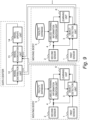
- FIG. 8 is a diagram illustrating an overall configuration of a facility inspection system according to Embodiment 4 of the present invention.
- An object of the present embodiment is to provide a facility inspection system in which a traveling space of a moving body is recognized from an image, a region in three-dimensional data at which a facility to be inspected may be present is limited based on the recognized traveling space, and labeled training information to be used for object detection is automatically created.
- FIG. 8 the facility inspection system of the present embodiment is implemented by adding a traveling space recognition unit 11 to the configuration shown in FIG. 1(a) of Embodiment 1.
- the traveling space recognition unit 11 recognizes a traveling space of the moving body from an image acquired by the first sensor 1, calculates a region at which a facility to be inspected may be present at the periphery of the recognized traveling space, and supplies information on the calculated region to the labeled training information creation unit 4.
- an outer periphery of the traveling space may be set as one region, different ranges at the top, bottom, left, and right of the traveling space may be set, ranges different for each traveling section may be set, and ranges different for each facility to be inspected may be set.
- the labeled training information creation unit 4 reads the facility database 5, and specifies, in the three-dimensional data acquired by the second sensor 2, a region matching with dimension data of a facility from the region at which the facility to be inspected may be present.
- the traveling space recognized by the traveling space recognition unit 11 can be estimated to be between white lines detected on the left and right sides based on white lines (lane marks or the like) detected in the image.
- the traveling space can be estimated to be a predetermined region in an upward direction and right and left directions from a position of the track based on the detected track.
- the facility to be inspected is disposed outside the traveling space, instead of being in the traveling space in which the moving body travels. Therefore, when the labeled training information creation unit 4 specifies a region matching with dimension data of a facility from the three-dimensional data, by limiting a search range to the outside of the traveling space, a process time required for the search can be shortened, and erroneous detection of the facility to be inspected in the traveling space can be reduced.
- the traveling space of the moving body is recognized based on the image
- the region in the three-dimensional data at which the facility to be inspected may be present is limited based on the traveling space
- the process time when the labeled training information to be used for object detection is automatically created can be shortened, and the creation of erroneous labeled training information can be reduced.
- the facility inspection system of the present embodiment is implemented by adding a model distribution unit 12, a model aggregation unit 13, and a model update unit 14 to the configuration shown in FIG. 1(a) of Embodiment 1.
- the model distribution unit 12 distributes the commonly used object detection models to the object detection units 3 of the plurality of moving bodies.
- labeled training information for the object detection unit 3 is created in any of the configurations described in Embodiments 1 to 4, the object detection model is trained, and the trained object detection models updated by the model aggregation unit 13 are aggregated into the data center.
- the object detection models to be aggregated may be all of the object detection models or only differences generated due to the update. By aggregating only the differences, an amount of data to be transmitted can be reduced.
- the model update unit 14 updates the commonly used object detection models based on the aggregated object detection models.
- the commonly used object detection models can be trained by repeating the above process.
- the configuration of the present embodiment when the configuration of the present embodiment is used in an obstacle detection system in front of the moving body, it is better not to transmit a captured image of a person as a main learning target of the object detection unit 3 to the outside of the moving body via a network line from the viewpoint of privacy protection.
- the commonly used object detection models can be trained while protecting privacy of the person to be used for training.
- the model distribution unit 12, the model aggregation unit 13, and the model update unit 14 are provided in the data center disposed in a place different from the moving bodies, but these processing units may be provided in one of the plurality of moving bodies so as to share the common object detection models.
- the facility inspection system can be implemented in which the plurality of moving bodies are connected to the data center in the edge cloud configuration, the common object detection models are distributed to the plurality of moving bodies and trained, and the training results are aggregated to update the common object detection models.
- the present invention may be applied to the facility inspection system for inspecting the facility such as a sign, but the present invention may be applied to other applications.
- the present invention may be applied to the obstacle detection system in front of the moving body described in Embodiment 5.
- the moving body may be an automobile, a railway vehicle, a streetcar, a drone, and the like.
- the facility inspection system includes: the first sensor 1 mounted on a moving body and configured to capture an image of a periphery of a traveling space; the second sensor 2 mounted on the moving body and configured to acquire three-dimensional data of the periphery of the traveling space; the facility database 5 configured to store dimension data of one or more types of facilities to be inspected; the labeled training information creation unit 4 configured to create labeled training information by specifying a region matching with the dimension data from the three-dimensional data; the object detection unit 3 configured to input the captured image to an object detection model and output a name and a region of each of the facilities to be inspected; and the learning unit 6 configured to learn, using at least the three-dimensional data, an internal parameter of the object detection model such that an output result of the object detection unit approaches the labeled training information, so that the labeled training information to be used for object detection can be automatically created by specifying the region matching with the dimension data of the facility from the three-dimensional data of the traveling space.
- the facility to be inspected is detected from the image captured by the first sensor 1 after the learning of the learning unit 6 is completed, a state of the periphery of the moving body is grasped using only the first sensor 1 in the operation phase, and the present system after completion of learning can be mounted on many moving bodies while reducing a cost, thereby enabling facility inspection over a wide area.
- the facility inspection system further includes: the position information acquisition unit 7 configured to acquire current position information of the moving body; and the labeled training information creation method control unit 8 configured to supply information on the facility to be inspected to the labeled training information creation unit 4, and the labeled training information creation method control unit 8 is configured to acquire the dimension data and arrangement location information of the facility to be inspected from the facility database 5, compare the acquired arrangement location information with the current position information of the moving body, and supply the information on the facility to be inspected to the labeled training information creation unit 4 at a timing at which the moving body approaches a location at which the facility to be inspected is present, so that it is possible to stop an operation of the labeled training information creation unit 4 at a position at which no facility is present, reduce the power consumption when the labeled training information is created, and reduce creation of erroneous labeled training information.
- the facility inspection system further includes: the position information acquisition unit 7 configured to acquire current position information of the moving body; the second sensor database 9 configured to store the three-dimensional data acquired by the second sensor 2 and the position information of the moving body in association with each other; and the interpolation unit 10 configured to read out the three-dimensional data acquired in the past from the second sensor database 9, interpolate the current three-dimensional data using the three-dimensional data acquired in the past at the same location, and output the interpolated three-dimensional data, so that the three-dimensional data acquired at the current time point can be interpolated using the three-dimensional data acquired in the past at the same location, and a spatial measurement resolution of three-dimensional data to be used for creating the labeled training information can be improved.
- the moving body is a railway vehicle, and the moving body travels at the same position every day, so that data of the same scene can be repeatedly acquired and high-quality labeled training information can be created.
- the moving body is a railway vehicle
- the traveling space recognition unit 11 is configured to detect a track from the image captured by the first sensor 1 and recognize the traveling space of the moving body, so that the traveling space can be reliably recognized and the creation of erroneous labeled training information can be reduced.
- a state determination system includes: the state determination device (moving body); and a center device (data center), the center device includes: the model distribution unit 12 configured to distribute the object detection models commonly used in the object detection units of a plurality of the moving bodies to the object detection units of the respective moving bodies; the model aggregation unit 13 configured to aggregate all of the object detection models trained in the plurality of moving bodies or a difference generated by update due to the training; and the model update unit 14 configured to update the commonly used object detection models based on the aggregated object detection models, and the object detection unit 3 of the moving body is configured to output the name and the region of the facility to be inspected using the object detection model distributed by the model distribution unit 12, training results of the respective moving bodies can be aggregated to update the common object detection models, and the facility to be inspected in a wide area can be efficiently learned.
- the present invention is not limited to the embodiments described above, and includes various modifications and equivalent configurations within the spirit of the appended claims.
- the embodiments described above have been described in detail for easy understanding of the present invention, and the present invention is not necessarily limited to those having all the configurations described above.
- a part of a configuration of a certain embodiment may be replaced with a configuration of another embodiment.
- the configuration of the other embodiment may be added to the configuration of the certain embodiment.
- a part of a configuration of each embodiment may be added to, deleted from, and replaced with another configuration.
- a part or all of the configurations, functions, processing units, processing methods described above or the like may be implemented by hardware, for example by designing an integrated circuit, or may be implemented by software by a processor interpreting and executing a program for implementing each function.
- Information such as a program, a table, and a file that implements each function can be stored in a storage device such as a memory, a hard disk, and a solid state drive (SSD), or a recording medium such as an IC card, an SD card, and a DVD.
- a storage device such as a memory, a hard disk, and a solid state drive (SSD), or a recording medium such as an IC card, an SD card, and a DVD.
- SSD solid state drive
- control lines and information lines indicate what is considered necessary for description, and not all the control lines and the information lines necessary for implementation are shown. In practice, it may be considered that almost all the configurations are connected to one another.
Landscapes
- Engineering & Computer Science (AREA)
- Theoretical Computer Science (AREA)
- Physics & Mathematics (AREA)
- General Physics & Mathematics (AREA)
- Data Mining & Analysis (AREA)
- General Engineering & Computer Science (AREA)
- Mechanical Engineering (AREA)
- Software Systems (AREA)
- Evolutionary Computation (AREA)
- Multimedia (AREA)
- Computer Vision & Pattern Recognition (AREA)
- Artificial Intelligence (AREA)
- Mathematical Physics (AREA)
- Medical Informatics (AREA)
- Computing Systems (AREA)
- Life Sciences & Earth Sciences (AREA)
- Bioinformatics & Cheminformatics (AREA)
- Bioinformatics & Computational Biology (AREA)
- Evolutionary Biology (AREA)
- Image Analysis (AREA)
- Train Traffic Observation, Control, And Security (AREA)
Abstract
A state determination device includes: a first sensor mounted on a moving body and configured to capture an image of a periphery of a traveling space; a second sensor mounted on the moving body and configured to acquire three-dimensional data of the periphery of the traveling space; a facility database configured to store dimension data of one or more types of facilities to be inspected; a labeled training information creation unit configured to create labeled training information by specifying a region matching with the dimension data from the three-dimensional data; an object detection unit configured to input the captured image to an object detection model and output a name and a region of each of the facilities to be inspected; and a learning unit configured to learn, using at least the three-dimensional data, an internal parameter of the object detection model such that an output result of the object detection unit approaches the labeled training information.
Description
- The present application claims priority from
Japanese Patent Application No. 2020-184282 filed on November 4, 2020 - The present invention relates to a state determination device.
- As a background art of the technical field, there is
JP2020-107174A PTL 1 discloses that "A pallet is an object to be transported by a transport device and includes a specific portion. Markers are attached to predetermined positions on the pallet during learning.", and that "A computer includes a processor, and during learning, the processor detects the positions of the markers from second image data based on first image data, cuts out, as labeled training data, a portion including the specific portion of the pallet from the second image data, performs machine learning using the labeled training data, and generates information necessary for an identifier.". - As a main application of a state determination device and a state determination method, for example, there is a facility inspection system that is mounted on a moving body and inspects a facility such as a sign using a captured image of a periphery thereof. In order to construct the present system using object detection based on a machine learning technique such as deep learning, an enormous number of man-hours may be required to create labeled training information.
- In the technique described in
JP2020-107174A JP2020-107174A - An object of the present invention is to provide a state determination device and a state determination method for automatically creating labeled training information, to be used for object detection, by specifying a region matching with dimension data of a facility based on three-dimensional data of a periphery of a traveling space.
- A representative example of the invention disclosed in the present application is as follows. That is, a state determination device includes: a first sensor mounted on a moving body and configured to capture an image of a periphery of a traveling space; a second sensor mounted on the moving body and configured to acquire three-dimensional data of the periphery of the traveling space; a facility database configured to store dimension data of one or more types of facilities to be inspected; a labeled training information creation unit configured to create labeled training information by specifying a region matching with the dimension data from the three-dimensional data; an object detection unit configured to input the captured image to an object detection model and output a name and a region of each of the facilities to be inspected; and a learning unit configured to learn, using at least the three-dimensional data, an internal parameter of the object detection model such that an output result of the object detection unit approaches the labeled training information. Advantageous Effects of Invention
- According to one aspect of the present invention, the labeled training information to be used for object detection can be automatically created. Problems, configurations, and effects other than those described above will be clarified with the following description of embodiments.
-
- [
FIG. 1(a)] FIG. 1(a) is a diagram illustrating an overall configuration in a learning phase of a facility inspection system according toEmbodiment 1 of the present invention. - [
FIG. 1(b)] FIG. 1(b) is a diagram illustrating an overall configuration in an operation phase of the facility inspection system according toEmbodiment 1 of the present invention. - [
FIG. 2(a)] FIG. 2(a) is a diagram illustrating an image acquired in the learning phase of the facility inspection system according toEmbodiment 1 of the present invention. - [
FIG. 2(b)] FIG. 2(b) is a diagram illustrating three-dimensional data acquired in the learning phase of the facility inspection system according toEmbodiment 1 of the present invention. - [
FIG. 2(c)] FIG. 2(c) is a diagram illustrating labeled training information created in the learning phase of the facility inspection system according toEmbodiment 1 of the present invention. - [
FIG. 3] FIG. 3 is a diagram illustrating an operation of the facility inspection system according toEmbodiment 1 of the present invention when the labeled training information is created for a facility to be inspected disposed at a curve. - [
FIG. 4(a)] FIG. 4(a) is a diagram illustrating an object detection result in a state immediately after the start of training of an object detection unit in the facility inspection system according toEmbodiment 1 of the present invention. - [
FIG. 4(b)] FIG. 4(b) is a diagram illustrating an object detection result in a state after training of the object detection unit progresses in the facility inspection system according toEmbodiment 1 of the present invention. - [
FIG. 5] FIG. 5 is a flowchart illustrating an example of an internal process in the facility inspection system according toEmbodiment 1 of the present invention. - [
FIG. 6] FIG. 6 is a diagram illustrating an overall configuration of a facility inspection system according toEmbodiment 2 of the present invention. - [
FIG. 7] FIG. 7 is a diagram illustrating an overall configuration of a facility inspection system according toEmbodiment 3 of the present invention. - [
FIG. 8] FIG. 8 is a diagram illustrating an overall configuration of a facility inspection system according toEmbodiment 4 of the present invention. - [
FIG. 9] FIG. 9 is a diagram illustrating an overall configuration of a facility inspection system according toEmbodiment 5 of the present invention. - Embodiments of the present invention will be described below with reference to the drawings.
- In the present embodiment, a facility inspection system which is a main application of a state determination device, a state determination system, and a state determination method of the present invention will be described. An object of the facility inspection system is to inspect the presence or absence of dirt, damage, or the like in a facility such as a sign using a captured image of a periphery of a moving body.
-
FIGS. 1(a) and 1(b) are diagrams illustrating an overall configuration of the facility inspection system according toEmbodiment 1 of the present invention, andFIGS. 2(a) to 4(b) are schematic diagrams illustrating an operation of the facility inspection system according toEmbodiment 1 of the present invention. In the present embodiment, the facility inspection system will be described in which labeled training information to be used for object detection is automatically created by acquiring three-dimensional data of a periphery of a traveling space and specifying a region matching with dimension data of a facility from the three-dimensional data while capturing a training image for object detection. In the present embodiment, the traveling space is a range in which the moving body (for example, a train or an automobile) can travel, and a facility to be inspected is disposed around an outside of the traveling space. - A configuration and an operation of the facility inspection system according to
Embodiment 1 of the present invention will be described. As shown inFIG. 1(a) , the facility inspection system of the present embodiment includes afirst sensor 1, asecond sensor 2, anobject detection unit 3, a labeled traininginformation creation unit 4, afacility database 5, and alearning unit 6. Thefirst sensor 1 is a device such as a camera that acquires an image. Thesecond sensor 2 is a device such as a lidar, a millimeter wave radar, and a stereo camera that acquires spatial three-dimensional data. The lidar is characterized in that highly accurate point cloud data can be acquired, the millimeter wave radar is characterized in that point cloud data with a low decomposition ability can be acquired regardless of a surrounding environment, and the stereo camera is characterized in that a distance image can be obtained at a low cost. Thefirst sensor 1 and thesecond sensor 2 are synchronized and acquire data at the same timing. Thefacility database 5 stores actual dimension data of the facility to be inspected. Thefacility database 5 may store data on a position or a height at which the facility to be inspected is disposed. The facility to be inspected is not limited to one type, and may be of a plurality of types. The dimension data stored in thefacility database 5, and an upper limit value and a lower limit value of a dimension of the facility to be inspected may be used, or an error range that may occur between a design value and recognition of the facility to be inspected may be used. The error range may hold different values for each sensor. - In the facility inspection system, in a learning phase, all the components are active as shown in
FIG. 1(a) , and in an operation phase after completion of learning, thefirst sensor 1 and theobject detection unit 3 are active as shown inFIG. 1(b) . In the operation phase, by grasping a state of the periphery of the moving body using only thefirst sensor 1, the present system after completion of learning can be mounted on many moving bodies while reducing a cost, thereby enabling facility inspection over a wide area. - An operation in the learning phase will be described with reference to
FIG. 1(a) . First, thefirst sensor 1 captures an image of a state of the periphery of the moving body and acquires the image. Thesecond sensor 2 acquires three-dimensional data of the periphery of the moving body. At this time, when the three-dimensional data is point cloud data, for example, the three-dimensional data may be appropriately converted into a distance image that matches with the image in a capturing direction and an angle of view. In addition, the three-dimensional data is prepared such that correspondence between a subject in the image and the three-dimensional data can be obtained. The labeled traininginformation creation unit 4 reads thefacility database 5 and specifies a region matching with the dimension data of the facility from the three-dimensional data. Then, the specified region is converted into a coordinate system in the captured image. Then, a name of the facility and information on the specified region are output as labeled training information to be used for object detection in the captured image. Theobject detection unit 3 includes an object detection model such as a deep neural network (DNN) therein, receives the captured image and the three-dimensional data, and outputs a name and a region of the facility to be inspected as a detection result. Thelearning unit 6 updates an internal parameter of the object detection model so as to reduce a difference between the output labeled training information and the detection result, that is, to increase a detection accuracy (accuracy of identifying the facility name and accuracy of specifying the region) of theobject detection unit 3. The accuracy of specifying the region can be calculated using, for example, an intersection over union (IoU). - The
learning unit 6 may update the internal parameter using the image and the labeled training information as a pair. Alternatively, thelearning unit 6 may update the internal parameter using a predetermined number of pieces of labeled training information stored in a labeled training information buffer and a predetermined number of captured images stored in an image buffer. By learning using a plurality of images, more general-purpose image features can be learned. -
FIGS. 2(a) to 2(c) are schematic diagrams illustrating the operation in the learning phase of the facility inspection system according to an embodiment of the present invention. An image F201 captured by thefirst sensor 1 shows a traffic light F202 to be inspected, as shown inFIG. 2(a) . At this time, in three-dimensional data (distance image) F203 acquired at the same timing, as shown inFIG. 2(b) , there is a region F204 matching with a dimension of a traffic light read from thefacility database 5. Labeled training information F205 (seeFIG. 2(c) ) of theobject detection unit 3 is created by finding out the region F204 matching with a dimension of a traffic light by searching. - An example of the method for searching for the region F204 matching with a dimension of a traffic light will be described. First, in the three-dimensional data (distance image) F203, a facility candidate region group F206 having a predetermined size at a position above the ground surface is calculated. Then, when a region satisfying a lower limit and an upper limit of the dimension of the facility to be searched for which are read from the
facility database 5 is extracted from the facility candidate region group F206, the region F204 matching with a dimension of a traffic light can be specified. When a condition related to a arrangement position such as a height at which the facility to be searched for is disposed is recorded in thefacility database 5, in a step of calculating the facility candidate region group F206 or in a step of specifying the region F204 matching with a dimension of a traffic light, erroneous specifications can be reduced by performing a filtering process according to the condition of the arrangement position. - When the stereo camera is used as the
second sensor 2, a distance image is obtained as three-dimensional data by calculating a parallax at each pixel position between left and right captured images. On the other hand, when the lidar and the millimeter wave radar are used as thesecond sensor 2, discrete point cloud data forming a space is obtained as three-dimensional data.FIGS. 2(b) and2(c) show a state of searching for a traffic light in the distance image, but the region matching with a dimension of a traffic light may be found by searching in a point cloud state, and then converted into a coordinate system in the image captured by thefirst sensor 1. -
FIG. 3 is a schematic diagram of an operation when the labeled training information of the facility to be inspected and disposed at a curve is created. Since a sharp curve has a large cant, an image or three-dimensional data is acquired in an inclined state. Therefore, the labeled training information is created in consideration of influence of the inclination. As information on the inclination, for example, a gyro sensor mounted on the moving body or design values of a track to be laid can be used. When searching for the region matching with a dimension of a traffic light, for example, the search is performed by adjusting the lower limit and the upper limit of the dimension to be searched for (a dimension in a horizontal direction is increased and a dimension in a vertical direction is decreased) in consideration of the influence of the inclination. Alternatively, the search may be performed after correcting the inclination of the entire three-dimensional data so as to match with an actual arrangement situation of a traffic light F302. After the search, labeled training information F303 is created based on a search result and inclination information so as to include the traffic light F302 in an image F301 captured by thefirst sensor 1. - For example, when the moving body is a streetcar, since a traveling space of the streetcar may be adjacent to or overlap with a traveling space of an automobile, various objects such as an automobile or a two-wheeled vehicle are reflected in the
first sensor 1 and thesecond sensor 2. Therefore, when a facility to be inspected is searched for using dimension data, for example, a detection unit that detects the automobile or the two-wheeled vehicle based on the image is separately provided, and filtering is performed on the three-dimensional data so as to exclude, from a search range, a position at which the automobile or the two-wheeled vehicle is detected, thereby reducing erroneous determinations of specifying these objects as a facility to be inspected. -
FIG. 4(a) is a schematic diagram illustrating an object detection result in a state immediately after the start of training of theobject detection unit 3, andFIG. 4(b) is a schematic diagram illustrating an object detection result in a state after training of theobject detection unit 3 progresses. As shown inFIG. 4 (a) , since image features of the traffic light cannot be suitably captured immediately after the start of training of theobject detection unit 3, a detection result F401 immediately after the start of training includes erroneous detection indicating places at which no traffic light is present and non-detection in which the traffic light is missed. Eventually, the learning of the image features of the traffic lights progress, and as shown inFIG. 4(b) , a detection result F402 after the learning progresses indicates that a position or a size of the traffic light can be suitably estimated. In the facility inspection system of the present invention, it is possible to automatically create the labeled training information and train theobject detection unit 3 in a process during which the moving body travels. - An object detection performance can be improved by using the three-dimensional data acquired by the
second sensor 2 when training the object detection model for detecting the facility to be inspected from the image acquired by thefirst sensor 1. A first example of a learning method is a method of treating both the image and the three-dimensional data as input data and learning the labeled training information associated with the input data. That is, an object detection task for estimating a name and a region of the facility to be inspected is trained based on both the three-dimensional data and the image, and knowledge acquired through the object detection task based on the three-dimensional data is utilized for detecting an object from the image. In the first example, an accuracy of detecting an object from the image can be improved by embedding knowledge that cannot be acquired based on only an image in the object detection model. A second example of the learning method is a method of learning by treating the image as input data and the three-dimensional data as labeled training information different from that used for object detection. That is, the object detection task based on the image and a distance estimation task for estimating distance information to an object based on the image are simultaneously trained. In the second example, an accuracy of the object detection task itself can be improved by solving multiple different tasks at the same time and promoting the acquisition of a latent knowledge common to the multiple tasks. - An operation in the operation phase will be described with reference to
FIG. 1(b) . First, thefirst sensor 1 captures an image of a state of the periphery of the moving body and acquires the image. Then, the trainedobject detection unit 3 receives the image acquired by thefirst sensor 1 and outputs a name and a region of a facility to be inspected as a detection result. - As an example of a method of confirming a reliability of an operation of the
object detection unit 3, a process of visualizing a detection basis of the object detection model provided in theobject detection unit 3 may be added to theobject detection unit 3. As a method of visualizing the detection basis, for example, there is a method of highlighting an internal signal of a DNN that greatly contributes to the output of the detection result (for example, highlighting in a heat map representing a degree of reaction). For example, when an object other than the facility to be inspected is erroneously detected in the operation phase, similar erroneous detection of the object can be reduced by visualizing a determination basis of the erroneous detection and additionally learning a scene similar to an erroneous detection scene. - In a subsequent stage of the
object detection unit 3, an extraction processing unit may be provided that extracts and stores a facility region detected from the image so as to facilitate subsequent inspection, or an abnormality determination unit may be provided that automatically determines the presence or absence of dirt, damage, or the like. - Both the
first sensor 1 and thesecond sensor 2 are mounted on the moving body and acquire a state of the periphery thereof. When the facility inspection system is used for inspection of a railway sign or the like, the moving body is a railway vehicle. When all of theobject detection unit 3, the labeled traininginformation creation unit 4, thefacility database 5, and thelearning unit 6 are mounted on the moving body, learning can be performed under a suitable condition in which influence of communication delay is small. Depending on convenience of hardware mounting, a part of the configuration (for example, theobject detection unit 3, the labeled traininginformation creation unit 4, thefacility database 5, and the learning unit 6) may be provided in a facility on the ground such as a data center outside the moving body, and learning may be performed while performing communication. -
FIG. 5 shows an example of a process flow of the present embodiment. After being operated, the facility inspection system proceeds to a process loop, and in step S501, the presence or absence of an operation end command for the facility inspection system of the present embodiment is monitored in the process loop. When the operation end command is detected, the process ends. On the other hand, when no operation end command can be detected and the operation is continued, in step S502, three-dimensional data of the periphery of the moving body is acquired by thesecond sensor 2. In step S503, the three-dimensional data is searched for a region matching with dimension data of a facility by referring to thefacility database 5. In step S504, it is determined whether there is a facility to be inspected, that is, whether the facility to be inspected is detected by the search. When the facility to be inspected is detected, in step S505, labeled training information to be used for object detection in the image captured by thefirst sensor 1 is created. Then, in step S506, a captured image of the periphery of the moving body is acquired from thefirst sensor 1. In step S507, the acquired image is input to the object detection model, and a detection result is output. In step S508, an internal parameter of the object detection model is updated to reduce a difference between the created labeled training information and the output detection result, that is, to improve a detection accuracy of the object detection model. - The process flow shown in
FIG. 5 illustrates a method of training the object detection model each time an image is acquired from thefirst sensor 1, but a labeled training information buffer and an image buffer may be provided, and the internal parameter may be updated using a predetermined number of pieces of labeled training information stored in the labeled training information buffer and a predetermined number of captured images stored in the image buffer. By learning using a plurality of images, more general-purpose image features can be learned. - According to the above process flow, the facility inspection system that continuously performs an internal process of the present embodiment can be implemented.
- As described above, in
Embodiment 1 of the present invention, by acquiring the three-dimensional data of the periphery of the traveling space and specifying the region matching with the dimension data of the facility from the three-dimensional data while capturing the training image for object detection, it is possible to automatically create the labeled training information to be used by the facility inspection system for object detection. -
FIG. 6 is a diagram illustrating an overall configuration of a facility inspection system according toEmbodiment 2 of the present invention. An object of the present embodiment is to provide a facility inspection system in which labeled training information to be used for object detection is automatically created by acquiring position information of a moving body and specifying a region matching with dimension data of a facility at a current location of the moving body. - A configuration and an operation of the facility inspection system according to
Embodiment 2 of the present invention will be described. As illustrated inFIG. 6 , the facility inspection system of the present embodiment is implemented by adding a positioninformation acquisition unit 7 and a labeled training information creation method control unit 8 to the configuration shown inFIG. 1(a) ofEmbodiment 1. - As the position
information acquisition unit 7, for example, a GNSS receiver such as a GPS is used. The positioninformation acquisition unit 7 acquires current position information of the moving body. The labeled training information creation method control unit 8 acquires dimension data and arrangement location information of a facility to be inspected from thefacility database 5, compares the arrangement location information with the current position information of the moving body acquired by the positioninformation acquisition unit 7, activates the labeled traininginformation creation unit 4 at a timing when the moving body approaches a location at which a facility is present, and supplies the name and the dimension data of the facility to be inspected acquired from thefacility database 5 to the labeled traininginformation creation unit 4. The labeled traininginformation creation unit 4 creates labeled training information based on the supplied name and dimension data of the facility to be inspected at a timing when the name and the dimension data of the facility to be inspected are supplied. Thelearning unit 6 updates an internal parameter of theobject detection unit 3 at a timing when the labeled training information is supplied. - When the
facility database 5 includes the arrangement location information of the facility to be inspected, the creation of erroneous labeled training information can be reduced by creating the labeled training information only at the timing when the moving body approaches the location at which the facility is present. In particular, when there are a plurality of types of facilities to be inspected and dimension data of the facilities are similar, erroneous detection of the facility can be reduced. - In the configuration shown in
FIG. 6 , the current position information of the moving body acquired by the positioninformation acquisition unit 7 is supplied only to the labeled training information creation method control unit 8, but for example, the current position information of the moving body acquired by the positioninformation acquisition unit 7 may also be supplied to both thefirst sensor 1 and thesecond sensor 2, and the data may be acquired from each sensor only at the timing when the moving body approaches the location at which the facility is present. The power consumption can be reduced by acquiring the sensor data only at a necessary timing. - Alternatively, when the labeled training
information creation unit 4 attempts to create the labeled training information at the timing when the moving body approaches the location at which the facility is present, but when the region matching with the dimension data of the facility cannot be specified from the three-dimensional data, a failure in specifying the region may be stored as a log. In this situation, there is a possibility that the facility significantly deviates from a normal arrangement situation, and it is also possible to determine the presence or absence of an abnormality such as a remarkable arrangement defect in a process of the learning phase of the present system in which the learning is performed while the labeled training information for theobject detection unit 3 is created. - As described above, according to
Embodiment 2 of the present invention, by acquiring the position information of the moving body and specifying the region matching with the dimension data of the facility at the current location of the moving body, the power consumption when the labeled training information to be used by the facility inspection system for object detection is automatically created can be reduced, and the creation of erroneous labeled training information can be reduced. -
FIG. 7 is a diagram illustrating an overall configuration of a facility inspection system according toEmbodiment 3 of the present invention. An object of the present embodiment is to provide a facility inspection system in which three-dimensional data acquired at the current time point is interpolated by using three-dimensional data acquired in the past at the same location, thereby improving a spatial measurement resolution of the periphery of a moving body and automatically creating labeled training information to be used for object detection. - A configuration and an operation of the facility inspection system according to
Embodiment 3 of the present invention will be described. As shown inFIG. 7 , the facility inspection system of the present embodiment is implemented by adding the positioninformation acquisition unit 7, asecond sensor database 9, and aninterpolation unit 10 to the configuration shown inFIG. 1(a) ofEmbodiment 1. - The
second sensor database 9 stores three-dimensional data acquired by thesecond sensor 2 during traveling and position information of the moving body in association with each other, and supplies the three-dimensional data acquired in the past at the same location to theinterpolation unit 10. Theinterpolation unit 10 interpolates the three-dimensional data acquired at the current time point by using the three-dimensional data acquired in the past at the same location, and outputs the interpolated three-dimensional data. - When three-dimensional data is acquired as a discrete point cloud forming a space by using, for example, a lidar or a millimeter wave radar as the
second sensor 2, a portion at which no point cloud is present cannot be measured. In particular, since a density of an acquirable point cloud is low when a speed of the moving body is high, the spatial measurement resolution decreases. Therefore, by interpolating the portion at which no point cloud is present by using the three-dimensional data acquired in the past at the same location, the density of the point cloud can be increased and the spatial measurement resolution can be improved. One or more of pieces of past three-dimensional data may be used for interpolation. In addition, the past three-dimensional data used for interpolation may be data at the same time or data at a different time. - In the interpolation of the three-dimensional data, for example, the current point cloud and the past point cloud are matched with each other, or one or both of the point clouds are converted into meshes and then matched with each other, and the three-dimensional data can be interpolated by calculating an alignment parameter in which space structures indicated by both point clouds match each other. In particular, when the moving body is a railway vehicle, since traveling of the railway vehicle is limited to a track, three-dimensional data under approximate conditions can be repeatedly acquired, a large amount of three-dimensional data to be used for interpolation can be held, and the spatial measurement resolution can be efficiently improved. Accordingly, an accuracy of specifying a region matching with dimension data of a facility at a current location of the moving body can be increased, and omissions and mistakes in creating the labeled training information can be reduced.
- As described above, in
Embodiment 3 of the present invention, by interpolating the three-dimensional data acquired at the current time point by using the three-dimensional data acquired in the past at the same location, it is possible to improve the spatial measurement resolution of the periphery of the moving body when the labeled training information to be used for object detection is automatically created. -
FIG. 8 is a diagram illustrating an overall configuration of a facility inspection system according toEmbodiment 4 of the present invention. An object of the present embodiment is to provide a facility inspection system in which a traveling space of a moving body is recognized from an image, a region in three-dimensional data at which a facility to be inspected may be present is limited based on the recognized traveling space, and labeled training information to be used for object detection is automatically created. - A configuration and an operation of the facility inspection system according to
Embodiment 4 of the present invention will be described. As shown inFIG. 8 , the facility inspection system of the present embodiment is implemented by adding a travelingspace recognition unit 11 to the configuration shown inFIG. 1(a) ofEmbodiment 1. - The traveling
space recognition unit 11 recognizes a traveling space of the moving body from an image acquired by thefirst sensor 1, calculates a region at which a facility to be inspected may be present at the periphery of the recognized traveling space, and supplies information on the calculated region to the labeled traininginformation creation unit 4. For the region at which the facility to be inspected may be present, an outer periphery of the traveling space may be set as one region, different ranges at the top, bottom, left, and right of the traveling space may be set, ranges different for each traveling section may be set, and ranges different for each facility to be inspected may be set. The labeled traininginformation creation unit 4 reads thefacility database 5, and specifies, in the three-dimensional data acquired by thesecond sensor 2, a region matching with dimension data of a facility from the region at which the facility to be inspected may be present. - For example, if the moving body is an automobile, the traveling space recognized by the traveling
space recognition unit 11 can be estimated to be between white lines detected on the left and right sides based on white lines (lane marks or the like) detected in the image. Alternatively, for example, if the moving body is a railway vehicle, a track can be detected in the image, and the traveling space can be estimated to be a predetermined region in an upward direction and right and left directions from a position of the track based on the detected track. - The facility to be inspected is disposed outside the traveling space, instead of being in the traveling space in which the moving body travels. Therefore, when the labeled training
information creation unit 4 specifies a region matching with dimension data of a facility from the three-dimensional data, by limiting a search range to the outside of the traveling space, a process time required for the search can be shortened, and erroneous detection of the facility to be inspected in the traveling space can be reduced. - As described above, according to
Embodiment 4 of the present invention, the traveling space of the moving body is recognized based on the image, the region in the three-dimensional data at which the facility to be inspected may be present is limited based on the traveling space, the process time when the labeled training information to be used for object detection is automatically created can be shortened, and the creation of erroneous labeled training information can be reduced. -
FIG. 9 is a diagram illustrating an overall configuration of a facility inspection system according toEmbodiment 5 of the present invention. An object of the present embodiment is to provide a facility inspection system in which a plurality of moving bodies are connected to a data center in an edge cloud configuration, common object detection models are distributed to the plurality of moving bodies to perform training, and training results are aggregated to update the common object detection models. - A configuration and an operation of the facility inspection system according to
Embodiment 5 of the present invention will be described. As illustrated inFIG. 9 , the facility inspection system of the present embodiment is implemented by adding amodel distribution unit 12, amodel aggregation unit 13, and amodel update unit 14 to the configuration shown inFIG. 1(a) ofEmbodiment 1. - The
model distribution unit 12 distributes the commonly used object detection models to theobject detection units 3 of the plurality of moving bodies. In each of the moving bodies, labeled training information for theobject detection unit 3 is created in any of the configurations described inEmbodiments 1 to 4, the object detection model is trained, and the trained object detection models updated by themodel aggregation unit 13 are aggregated into the data center. The object detection models to be aggregated may be all of the object detection models or only differences generated due to the update. By aggregating only the differences, an amount of data to be transmitted can be reduced. Themodel update unit 14 updates the commonly used object detection models based on the aggregated object detection models. The commonly used object detection models can be trained by repeating the above process. - According to the configuration shown in
FIG. 9 , it is possible to efficiently learn facilities to be inspected in a wide area by collecting data from the plurality of moving bodies. In addition, in the configuration, since no data such as the image and the three-dimensional data is transmitted from the moving body to the data center, the commonly used object detection models can be trained while maintaining a confidentiality of data. - For example, when the configuration of the present embodiment is used in an obstacle detection system in front of the moving body, it is better not to transmit a captured image of a person as a main learning target of the
object detection unit 3 to the outside of the moving body via a network line from the viewpoint of privacy protection. According to the configuration of the present embodiment, since no data is transmitted to the outside of the moving body, the commonly used object detection models can be trained while protecting privacy of the person to be used for training. - In the configuration shown in
FIG. 9 , themodel distribution unit 12, themodel aggregation unit 13, and themodel update unit 14 are provided in the data center disposed in a place different from the moving bodies, but these processing units may be provided in one of the plurality of moving bodies so as to share the common object detection models. - As described above, in
Embodiment 5 of the present invention, the facility inspection system can be implemented in which the plurality of moving bodies are connected to the data center in the edge cloud configuration, the common object detection models are distributed to the plurality of moving bodies and trained, and the training results are aggregated to update the common object detection models. - In the above-described embodiments, a case in which the present invention is applied to the facility inspection system for inspecting the facility such as a sign has been mainly described, but the present invention may be applied to other applications. For example, the present invention may be applied to the obstacle detection system in front of the moving body described in
Embodiment 5. The moving body may be an automobile, a railway vehicle, a streetcar, a drone, and the like. - As described above, the facility inspection system according to embodiments of the present invention includes: the
first sensor 1 mounted on a moving body and configured to capture an image of a periphery of a traveling space; thesecond sensor 2 mounted on the moving body and configured to acquire three-dimensional data of the periphery of the traveling space; thefacility database 5 configured to store dimension data of one or more types of facilities to be inspected; the labeled traininginformation creation unit 4 configured to create labeled training information by specifying a region matching with the dimension data from the three-dimensional data; theobject detection unit 3 configured to input the captured image to an object detection model and output a name and a region of each of the facilities to be inspected; and thelearning unit 6 configured to learn, using at least the three-dimensional data, an internal parameter of the object detection model such that an output result of the object detection unit approaches the labeled training information, so that the labeled training information to be used for object detection can be automatically created by specifying the region matching with the dimension data of the facility from the three-dimensional data of the traveling space. - In addition, since the facility to be inspected is detected from the image captured by the
first sensor 1 after the learning of thelearning unit 6 is completed, a state of the periphery of the moving body is grasped using only thefirst sensor 1 in the operation phase, and the present system after completion of learning can be mounted on many moving bodies while reducing a cost, thereby enabling facility inspection over a wide area. - In addition, the facility inspection system further includes: the position
information acquisition unit 7 configured to acquire current position information of the moving body; and the labeled training information creation method control unit 8 configured to supply information on the facility to be inspected to the labeled traininginformation creation unit 4, and the labeled training information creation method control unit 8 is configured to acquire the dimension data and arrangement location information of the facility to be inspected from thefacility database 5, compare the acquired arrangement location information with the current position information of the moving body, and supply the information on the facility to be inspected to the labeled traininginformation creation unit 4 at a timing at which the moving body approaches a location at which the facility to be inspected is present, so that it is possible to stop an operation of the labeled traininginformation creation unit 4 at a position at which no facility is present, reduce the power consumption when the labeled training information is created, and reduce creation of erroneous labeled training information. - In addition, the facility inspection system further includes: the position
information acquisition unit 7 configured to acquire current position information of the moving body; thesecond sensor database 9 configured to store the three-dimensional data acquired by thesecond sensor 2 and the position information of the moving body in association with each other; and theinterpolation unit 10 configured to read out the three-dimensional data acquired in the past from thesecond sensor database 9, interpolate the current three-dimensional data using the three-dimensional data acquired in the past at the same location, and output the interpolated three-dimensional data, so that the three-dimensional data acquired at the current time point can be interpolated using the three-dimensional data acquired in the past at the same location, and a spatial measurement resolution of three-dimensional data to be used for creating the labeled training information can be improved. - In addition, the facility inspection system further includes: the traveling
space recognition unit 11 configured to recognize the traveling space of the moving body from the image captured by thefirst sensor 1, and calculate a region at which the facility to be inspected is capable of being present based on the recognized traveling space, and the labeled traininginformation creation unit 4 is configured to read data from thefacility database 5, and create the labeled training information by specifying, in the three-dimensional data acquired by thesecond sensor 2, the region matching with the dimension data of the facility to be inspected from the region that is calculated by the travelingspace recognition unit 11 and at which the facility to be inspected is capable of being present, so that the traveling space of the moving body is recognized from the image, and the region in the three-dimensional data at which the facility to be inspected is capable of being present is limited based on the traveling space, and therefore, a processing time when the labeled training information is created can be shortened, and the creation of erroneous labeled training information can be reduced. - In addition, the moving body is a railway vehicle, and the moving body travels at the same position every day, so that data of the same scene can be repeatedly acquired and high-quality labeled training information can be created.
- In addition, the moving body is a railway vehicle, and the traveling
space recognition unit 11 is configured to detect a track from the image captured by thefirst sensor 1 and recognize the traveling space of the moving body, so that the traveling space can be reliably recognized and the creation of erroneous labeled training information can be reduced. - In addition, a state determination system includes: the state determination device (moving body); and a center device (data center), the center device includes: the
model distribution unit 12 configured to distribute the object detection models commonly used in the object detection units of a plurality of the moving bodies to the object detection units of the respective moving bodies; themodel aggregation unit 13 configured to aggregate all of the object detection models trained in the plurality of moving bodies or a difference generated by update due to the training; and themodel update unit 14 configured to update the commonly used object detection models based on the aggregated object detection models, and theobject detection unit 3 of the moving body is configured to output the name and the region of the facility to be inspected using the object detection model distributed by themodel distribution unit 12, training results of the respective moving bodies can be aggregated to update the common object detection models, and the facility to be inspected in a wide area can be efficiently learned. - The present invention is not limited to the embodiments described above, and includes various modifications and equivalent configurations within the spirit of the appended claims. For example, the embodiments described above have been described in detail for easy understanding of the present invention, and the present invention is not necessarily limited to those having all the configurations described above. In addition, a part of a configuration of a certain embodiment may be replaced with a configuration of another embodiment. In addition, the configuration of the other embodiment may be added to the configuration of the certain embodiment. In addition, a part of a configuration of each embodiment may be added to, deleted from, and replaced with another configuration.
- In addition, a part or all of the configurations, functions, processing units, processing methods described above or the like may be implemented by hardware, for example by designing an integrated circuit, or may be implemented by software by a processor interpreting and executing a program for implementing each function.
- Information such as a program, a table, and a file that implements each function can be stored in a storage device such as a memory, a hard disk, and a solid state drive (SSD), or a recording medium such as an IC card, an SD card, and a DVD.
- In addition, control lines and information lines indicate what is considered necessary for description, and not all the control lines and the information lines necessary for implementation are shown. In practice, it may be considered that almost all the configurations are connected to one another.
Claims (9)
- A state determination device comprising:a first sensor mounted on a moving body and configured to capture an image of a periphery of a traveling space;a second sensor mounted on the moving body and configured to acquire three-dimensional data of the periphery of the traveling space;a facility database configured to store dimension data of one or more types of facilities to be inspected;a labeled training information creation unit configured to create labeled training information by specifying a region matching with the dimension data from the three-dimensional data;an object detection unit configured to input the captured image to an object detection model and output a name and a region of each of the facilities to be inspected; anda learning unit configured to learn, using at least the three-dimensional data, an internal parameter of the object detection model such that an output result of the object detection unit approaches the labeled training information.
- The state determination device according to claim 1, wherein
after completion of the learning of the learning unit, the facility to be inspected is detected from the image captured by the first sensor. - The state determination device according to claim 1, further comprising:a position information acquisition unit configured to acquire current position information of the moving body; anda labeled training information creation method control unit configured to supply information on the facility to be inspected to the labeled training information creation unit, whereinthe labeled training information creation method control unit is configured to acquire the dimension data and arrangement location information of the facility to be inspected from the facility database, compare the acquired arrangement location information with the current position information of the moving body, and supply the information on the facility to be inspected to the labeled training information creation unit at a timing at which the moving body approaches a location at which the facility to be inspected is present.
- The state determination device according to claim 1, further comprising:a position information acquisition unit configured to acquire current position information of the moving body;a second sensor database configured to store the three-dimensional data acquired by the second sensor and the position information of the moving body in association with each other; andan interpolation unit configured to read out the three-dimensional data acquired in the past from the second sensor database, interpolate the current three-dimensional data using the three-dimensional data acquired in the past at the same location, and output the interpolated three-dimensional data.
- The state determination device according to claim 1, further comprising:a traveling space recognition unit configured to recognize the traveling space of the moving body from the image captured by the first sensor, and calculate a region at which the facility to be inspected is capable of being present based on the recognized traveling space, whereinthe labeled training information creation unit is configured to read data from the facility database, and create the labeled training information by specifying, in the three-dimensional data acquired by the second sensor, the region matching with the dimension data of the facility to be inspected from the region that is calculated by the traveling space recognition unit and at which the facility to be inspected is capable of being present.
- The state determination device according to claim 1, wherein
the moving body is a railway vehicle. - The state determination device according to claim 5, whereinthe moving body is a railway vehicle, andthe traveling space recognition unit is configured to detect a track from the image captured by the first sensor and recognize the traveling space of the moving body.
- A state determination system comprising:the state determination device according to any one of claims 1 to 7; anda center device communicably connected to the state determination device, whereinthe center device includes:a model distribution unit configured to distribute the object detection models commonly used in the object detection units in a plurality of the moving bodies to the object detection units of the respective moving bodies;a model aggregation unit configured to aggregate all of the object detection models trained in the plurality of moving bodies or a difference generated by update due to the training; anda model update unit configured to update the commonly used object detection models based on the aggregated object detection models, andthe object detection unit of the state determination device is configured to output the name and the region of the facility to be inspected using the object detection model distributed by the model distribution unit.
- A state determination method to be executed by a computer,the computer including an arithmetic unit configured to execute a predetermined process, a storage device connected to the arithmetic unit, and a facility database configured to store dimension data of one or more types of facilities to be inspected,the state determination method comprising the arithmetic unit executing:a step of acquiring data from a first sensor mounted on a moving body and configured to capture an image of a periphery of a traveling space;a step of acquiring data from a second sensor mounted on the moving body and configured to acquire three-dimensional data of the periphery of the traveling space;a labeled training information creation step of creating labeled training information by specifying a region matching with the dimension data from the three-dimensional data;an object detection step of inputting the captured image to an object detection model and outputting a name and a region of each of the facilities to be inspected; anda learning step of learning, using at least the three-dimensional data, an internal parameter of the object detection model such that an output result of the object detection step approaches the labeled training information.
Applications Claiming Priority (2)
| Application Number | Priority Date | Filing Date | Title |
|---|---|---|---|
| JP2020184282A JP7427569B2 (en) | 2020-11-04 | 2020-11-04 | Condition determination device, condition determination system, and condition determination method |
| PCT/JP2021/037487 WO2022097426A1 (en) | 2020-11-04 | 2021-10-08 | Status determination device, status determination system, and status determination method |
Publications (1)
| Publication Number | Publication Date |
|---|---|
| EP4242996A1 true EP4242996A1 (en) | 2023-09-13 |
Family
ID=81457105
Family Applications (1)
| Application Number | Title | Priority Date | Filing Date |
|---|---|---|---|
| EP21888979.8A Pending EP4242996A1 (en) | 2020-11-04 | 2021-10-08 | Status determination device, status determination system, and status determination method |
Country Status (3)
| Country | Link |
|---|---|
| EP (1) | EP4242996A1 (en) |
| JP (1) | JP7427569B2 (en) |
| WO (1) | WO2022097426A1 (en) |
Families Citing this family (1)
| Publication number | Priority date | Publication date | Assignee | Title |
|---|---|---|---|---|
| CN116992780B (en) * | 2023-09-25 | 2024-01-02 | 中南大学 | Temperature sensor arrangement method for digital electrolytic tank |
Family Cites Families (6)
| Publication number | Priority date | Publication date | Assignee | Title |
|---|---|---|---|---|
| JP6682833B2 (en) | 2015-12-04 | 2020-04-15 | トヨタ自動車株式会社 | Database construction system for machine learning of object recognition algorithm |
| JP6766844B2 (en) | 2018-06-01 | 2020-10-14 | 株式会社デンソー | Object identification device, mobile system, object identification method, object identification model learning method and object identification model learning device |
| JP7082545B2 (en) * | 2018-08-01 | 2022-06-08 | パナソニック インテレクチュアル プロパティ コーポレーション オブ アメリカ | Information processing methods, information processing equipment and programs |
| JP7029728B2 (en) | 2018-12-28 | 2022-03-04 | 住友ナコ フォ-クリフト株式会社 | Transport system, transport device, computer, learning method |
| JP2020184282A (en) | 2019-05-04 | 2020-11-12 | 五十嵐 敬一 | Copyright management system |
| JP2021047120A (en) * | 2019-09-19 | 2021-03-25 | 本田技研工業株式会社 | Recognition device, control system, recognition method and program |
-
2020
- 2020-11-04 JP JP2020184282A patent/JP7427569B2/en active Active
-
2021
- 2021-10-08 WO PCT/JP2021/037487 patent/WO2022097426A1/en unknown
- 2021-10-08 EP EP21888979.8A patent/EP4242996A1/en active Pending
Also Published As
| Publication number | Publication date |
|---|---|
| WO2022097426A1 (en) | 2022-05-12 |
| JP7427569B2 (en) | 2024-02-05 |
| JP2022074331A (en) | 2022-05-18 |
Similar Documents
| Publication | Publication Date | Title |
|---|---|---|
| US10996062B2 (en) | Information processing device, data management device, data management system, method, and program | |
| JP6826421B2 (en) | Equipment patrol system and equipment patrol method | |
| CN110163904A (en) | Object marking method, control method for movement, device, equipment and storage medium | |
| JPH10143659A (en) | Object detector | |
| JP2018092483A (en) | Object recognition device | |
| CN110197173B (en) | Road edge detection method based on binocular vision | |
| US11551411B2 (en) | Data processor, data processing method, and data processing program for determining correspondence relationships between laser scanning point clouds | |
| JP2017083245A (en) | Clearance limit determination device | |
| JP2022051770A (en) | Map generation system, map generation method and map generation program | |
| US20190385010A1 (en) | Determining geographical map features with multi-sensor input | |
| EP4242996A1 (en) | Status determination device, status determination system, and status determination method | |
| CN112686951A (en) | Method, device, terminal and storage medium for determining robot position | |
| CN112561859A (en) | Monocular vision-based steel belt drilling and anchor net identification method and device for anchoring and protecting | |
| US20210304518A1 (en) | Method and system for generating an environment model for positioning | |
| CN107767366B (en) | A kind of transmission line of electricity approximating method and device | |
| Hu et al. | A high-resolution surface image capture and mapping system for public roads | |
| CN110687548A (en) | Radar data processing system based on unmanned ship | |
| WO2023166411A1 (en) | Automatic digital inspection of railway environment | |
| US20190354781A1 (en) | Method and system for determining an object location by using map information | |
| CN115599119A (en) | Unmanned aerial vehicle keeps away barrier system | |
| JP2022074331A5 (en) | ||
| Izquierdo et al. | Road lane landmark extraction: a state-of-the-art review | |
| Cuypers et al. | Planimetric Rail Positioning Using Uav Photogrammetry: Towards Automated and Safe Railway Infrastructure Monitoring | |
| CN117784162B (en) | Target annotation data acquisition method, target tracking method, intelligent device and medium | |
| WO2024004325A1 (en) | External world recognition device and external world recognition method |
Legal Events
| Date | Code | Title | Description |
|---|---|---|---|
| STAA | Information on the status of an ep patent application or granted ep patent |
Free format text: STATUS: THE INTERNATIONAL PUBLICATION HAS BEEN MADE |
|
| PUAI | Public reference made under article 153(3) epc to a published international application that has entered the european phase |
Free format text: ORIGINAL CODE: 0009012 |
|
| STAA | Information on the status of an ep patent application or granted ep patent |
Free format text: STATUS: REQUEST FOR EXAMINATION WAS MADE |
|
| 17P | Request for examination filed |
Effective date: 20230426 |
|
| AK | Designated contracting states |
Kind code of ref document: A1 Designated state(s): AL AT BE BG CH CY CZ DE DK EE ES FI FR GB GR HR HU IE IS IT LI LT LU LV MC MK MT NL NO PL PT RO RS SE SI SK SM TR |
|
| DAV | Request for validation of the european patent (deleted) | ||
| DAX | Request for extension of the european patent (deleted) |