EP4242882A2 - Programmable customization of a user interface of an electronic equipment - Google Patents
Programmable customization of a user interface of an electronic equipment Download PDFInfo
- Publication number
- EP4242882A2 EP4242882A2 EP23160380.4A EP23160380A EP4242882A2 EP 4242882 A2 EP4242882 A2 EP 4242882A2 EP 23160380 A EP23160380 A EP 23160380A EP 4242882 A2 EP4242882 A2 EP 4242882A2
- Authority
- EP
- European Patent Office
- Prior art keywords
- electronic equipment
- input pattern
- user
- circuitry
- functionality
- Prior art date
- Legal status (The legal status is an assumption and is not a legal conclusion. Google has not performed a legal analysis and makes no representation as to the accuracy of the status listed.)
- Granted
Links
Images



Classifications
-
- G—PHYSICS
- G06—COMPUTING OR CALCULATING; COUNTING
- G06F—ELECTRIC DIGITAL DATA PROCESSING
- G06F18/00—Pattern recognition
- G06F18/20—Analysing
- G06F18/21—Design or setup of recognition systems or techniques; Extraction of features in feature space; Blind source separation
-
- A—HUMAN NECESSITIES
- A24—TOBACCO; CIGARS; CIGARETTES; SIMULATED SMOKING DEVICES; SMOKERS' REQUISITES
- A24F—SMOKERS' REQUISITES; MATCH BOXES; SIMULATED SMOKING DEVICES
- A24F40/00—Electrically operated smoking devices; Component parts thereof; Manufacture thereof; Maintenance or testing thereof; Charging means specially adapted therefor
- A24F40/50—Control or monitoring
-
- A—HUMAN NECESSITIES
- A24—TOBACCO; CIGARS; CIGARETTES; SIMULATED SMOKING DEVICES; SMOKERS' REQUISITES
- A24F—SMOKERS' REQUISITES; MATCH BOXES; SIMULATED SMOKING DEVICES
- A24F40/00—Electrically operated smoking devices; Component parts thereof; Manufacture thereof; Maintenance or testing thereof; Charging means specially adapted therefor
- A24F40/60—Devices with integrated user interfaces
-
- A—HUMAN NECESSITIES
- A24—TOBACCO; CIGARS; CIGARETTES; SIMULATED SMOKING DEVICES; SMOKERS' REQUISITES
- A24F—SMOKERS' REQUISITES; MATCH BOXES; SIMULATED SMOKING DEVICES
- A24F40/00—Electrically operated smoking devices; Component parts thereof; Manufacture thereof; Maintenance or testing thereof; Charging means specially adapted therefor
- A24F40/65—Devices with integrated communication means, e.g. wireless communication means
-
- G—PHYSICS
- G06—COMPUTING OR CALCULATING; COUNTING
- G06F—ELECTRIC DIGITAL DATA PROCESSING
- G06F18/00—Pattern recognition
- G06F18/20—Analysing
- G06F18/21—Design or setup of recognition systems or techniques; Extraction of features in feature space; Blind source separation
- G06F18/214—Generating training patterns; Bootstrap methods, e.g. bagging or boosting
-
- G—PHYSICS
- G06—COMPUTING OR CALCULATING; COUNTING
- G06N—COMPUTING ARRANGEMENTS BASED ON SPECIFIC COMPUTATIONAL MODELS
- G06N3/00—Computing arrangements based on biological models
- G06N3/02—Neural networks
- G06N3/04—Architecture, e.g. interconnection topology
- G06N3/0499—Feedforward networks
-
- G—PHYSICS
- G06—COMPUTING OR CALCULATING; COUNTING
- G06N—COMPUTING ARRANGEMENTS BASED ON SPECIFIC COMPUTATIONAL MODELS
- G06N3/00—Computing arrangements based on biological models
- G06N3/02—Neural networks
- G06N3/08—Learning methods
-
- G—PHYSICS
- G06—COMPUTING OR CALCULATING; COUNTING
- G06N—COMPUTING ARRANGEMENTS BASED ON SPECIFIC COMPUTATIONAL MODELS
- G06N3/00—Computing arrangements based on biological models
- G06N3/02—Neural networks
- G06N3/08—Learning methods
- G06N3/09—Supervised learning
-
- G—PHYSICS
- G06—COMPUTING OR CALCULATING; COUNTING
- G06N—COMPUTING ARRANGEMENTS BASED ON SPECIFIC COMPUTATIONAL MODELS
- G06N3/00—Computing arrangements based on biological models
- G06N3/02—Neural networks
- G06N3/08—Learning methods
- G06N3/091—Active learning
-
- H—ELECTRICITY
- H04—ELECTRIC COMMUNICATION TECHNIQUE
- H04L—TRANSMISSION OF DIGITAL INFORMATION, e.g. TELEGRAPHIC COMMUNICATION
- H04L63/00—Network architectures or network communication protocols for network security
- H04L63/08—Network architectures or network communication protocols for network security for authentication of entities
-
- H—ELECTRICITY
- H04—ELECTRIC COMMUNICATION TECHNIQUE
- H04L—TRANSMISSION OF DIGITAL INFORMATION, e.g. TELEGRAPHIC COMMUNICATION
- H04L63/00—Network architectures or network communication protocols for network security
- H04L63/08—Network architectures or network communication protocols for network security for authentication of entities
- H04L63/083—Network architectures or network communication protocols for network security for authentication of entities using passwords
Definitions
- the present disclosure relates generally to electronic equipments offering a plurality of controllable functionalities, and more to the customization of the user interface of such electronic equipments.
- Some electronic equipments offer a plurality of functionalities that are each controllable by means of an input pattern comprising at least one user input. This is notably the case of vaping devices or so-called electronic nicotine delivery systems (also known by the acronym "ENDS") producing an aerosol by heating an aerosol-forming substance mixed with air during a user vaping session.
- vaping devices or so-called electronic nicotine delivery systems (also known by the acronym "ENDS") producing an aerosol by heating an aerosol-forming substance mixed with air during a user vaping session.
- ETS electronic nicotine delivery systems
- the input pattern associated to a functionality of an electronic equipment is a default input pattern set by a manufacturer of this electronic equipment. Therefore, when the user of this electronic equipment wants to use this functionality, he has to reproduce the associated default input pattern with his electronic equipment or with an external device coupled to, and capable of remotely controlling, his electronic equipment. So, there is no possibility for the user to customize the input patterns associated respectively to the functionalities of his electronic equipment, and any other user knowing the default input patterns of an electronic equipment may use the latter.
- An electronic equipment, a device and a server for customizing a user interface based on recognition of input patterns associated to functionalities from recordings of group of user input(s), are provided substantially as shown in, and/or described in connection with, at least one of the figures, as set forth in the appended claims.
- the present description is directed to an electronic equipment 1, a device 2 and a server 3 for customizing a user interface based on recognition of input patterns, associated to functionalities offered by this electronic equipment 1, from recordings of a group or groups of user input(s).
- any type of user input is concerned, and notably gesture, squeeze, tap, tilt, rotation, movement, sound or word(s), for instance.
- the electronic equipment 1 is a vaping device, such as an electronic cigarette for generating an inhalable vapor from a liquid substrate or a heat-not-burn device for generating an inhalable vapor from heating a plant-based substrate, in particular tobacco, without combustion and pyrolysis thereof.
- the electronic equipment 1 could be of another type, as long as it may be used and carried by a user and offers at least one controllable functionality.
- the (user) device 2 is any connected electronic communication device, i.e. any electronic device comprising a communication interface allowing wireless communications with another electronic device using any known wireless communication protocol, in particular any of WiFi (IEEE 802.11), Bluetooth ® (IEEE 801.15.1), Zigbee (IEEE 802.15.4), LoRaWan or Sigfox protocols. So, for instance, the user device 2 could be any of a smartphone, an electronic tablet, a laptop or else a smartwatch.
- FIG. 1 An example of electronic equipment 1 according to an embodiment of the invention is illustrated in figure 1 .
- the electronic equipment 1 is a heat-not-burn device. But such an electronic equipment 1, that is a vaping device, could be also a liquid vaporization device.
- an electronic equipment 1 offers at least one controllable functionality and comprises at least a first circuitry 4 and a group of elements allowing generation of an aerosol by heating an aerosol-forming substance mixed with air during a vaping session of its user.
- each controllable functionality may comprise any of a locking/unlocking of the electronic equipment 1, a start of use of the electronic equipment 1, a stop of use of the electronic equipment 1, a communication of the electronic equipment 1 with an external device 2 or 3, a control of a heating element 10 of the electronic equipment 1, an opening/closing of a shutter controlling access to an internal chamber 6 of the electronic equipment 1, and a cleaning of this heating element 10.
- the above-mentioned group of elements of the electronic equipment 1 is housed in an external casing 5 comprising the internal chamber 6 in which a consumable 7 comprising the aerosol-forming substance 8 can be introduced.
- this consumable 7 may be a tobacco stick.
- the aerosol-forming substance 8 comprises tobacco and/or reconstituted tobacco material.
- the substance comprises homogenized tobacco material (i.e. reconstituted tobacco such as cast sheet, tobacco paper or laminated tobacco sheet) and one or more of tobacco lamina, cellulose fibre or flavor.
- the invention is not limited to this type of consumable 7.
- the consumable 7 may comprise a filter 9 attached at an end of the aerosol-forming substance 8.
- the consumable 7 is partly inserted into the internal chamber 6. However, in an embodiment, it could be fully inserted in the internal chamber 6.
- the aerosol-forming substance 8 is heated by the heating element (or heater) 10 that is supplied with electrical energy from a power source 11.
- the heating element 10 surrounds the internal chamber 6, and therefore a part of the consumable 7 (and more precisely its aerosol-forming substance 8) to heat the latter.
- the heating element 10 may be a thin film heater wrapped around the outer surface of the internal chamber 6 to heat its side walls and at least a part of its internal volume (which therefore defines a heating chamber).
- the heating element 10 could be a coil associated to a susceptor or a resistive coil heater.
- the heating element 10 could be located inside the consumable 7 or inside the internal chamber 6.
- the electrical energy supplied to the heating element 10 during a vaping session is controlled by the first circuitry 4, that may be provided onto a printed circuit board (or PCB) 12 (here housed into the external casing 5).
- the first circuitry 4 comprises at least a processor and a memory arranged for performing operations.
- the processor may be a digital signal processor (or DSP), or an application specific integrated circuit (ASIC), or else a field programmable gate array (FPGA).
- the processor may comprise integrated (or printed) circuits, or several integrated (or printed) circuits connected therebetween through wired or wireless connections.
- integrated (or printed) circuits refers here to any type of device capable of carrying out at least one electric or electronic operation.
- the memory may be a random access memory (RAM). But it may be any type of device arranged for storing program instructions for the associated processor.
- the functions of the first circuitry 4 may be carried out through the operation of program logic, through dedicated logic, through the interaction of program control and dedicated logic, or even partially manually (by a user). These functions may be provided through the use of dedicated hardware as well as hardware capable of executing software in association with appropriate software.
- the first circuitry 4 may also comprise, in addition with its processor(s) and memory(ies), an input interface, a mass memory (notably for storing intermediate data produced during its calculus and processing), and an output interface for delivering messages and instructions.
- the first circuitry 4 is configured to carry out at least five operations 100-140.
- the first operation 100 consists in receiving information designating a functionality of the electronic equipment 1 that is selected amongst its plurality of controllable functionalities.
- the functionality may be selected via a dedicated application running on the electronic equipment 1, and more precisely on its first circuitry 4, and controllable by the user by means of a user interface 13 connected to the first circuitry 4.
- the dedicated application could run on the user device 2 (here a smartphone) that is used by the user of the electronic equipment 1 and paired to the latter.
- the user selects the functionality via the dedicated application running on his user device 2 and the latter transmits the information designating the selected functionality to the electronic equipment 1.
- the electronic equipment 1 may comprise a communication interface 14 coupled to its first circuitry 4 and that allows communications with the paired user device 2.
- the transmission of this information may be carried out by means of a short-range wireless communication, for instance.
- a short-range wireless communication may be a Bluetooth communication, for instance.
- the second operation 110 carried out by the first circuitry 4 consists in receiving a plurality of recordings of a same group of at least one user input for the selected functionality.
- Each recording of a group of at least one user input may be carried out by at least one sensor via the above-mentioned dedicated application.
- the electronic equipment 1 may comprise each sensor 15-18, and in this embodiment each recording starts when the user handles his electronic equipment 1 and carries out a user input that is recorded by at least one sensor 15-18.
- each sensor be provided in an external device communicatively coupled (or intended to be coupled) to the electronic equipment 1.
- Such an external device may be the user device 2 or another device used by the user (for instance a virtual assistant).
- each recording starts when the user handles or uses his external device and carries out a user input that is recorded by at least one sensor.
- a user input may be a user action on the electronic equipment 1, a user gesture associated with the electronic equipment 1, a sequence of user actions on the electronic equipment 1, and a sequence of user gestures associated with the electronic equipment 1.
- any type of user input is concerned, and notably gesture, squeeze, tap, shake, tilt, rotation, movement, sound or word(s), for instance.
- a sensor 15-18 may be an accelerometer, a gyroscope, a pendulum, a strain gauge, button(s), a touch screen, or a microphone, for instance.
- a user action when the electronic equipment 1 comprises two strain gauges 15 and 16 arranged on two opposite faces of its external casing 5, a user action may consist in simultaneous squeezes on these opposite faces.
- a user action when the electronic equipment 1 comprises an accelerometer 17 arranged on another face of its external casing 5, a user action may consist in tapping at least one time on this other face.
- a user action when the electronic equipment 1 comprises at least one strain gauge 15, 16 and an accelerometer 17 a user action may consist in squeezing and tapping.
- the first circuitry 4 of the electronic equipment 1 may be configured to control the sensor(s) 15-18 to capture the plurality of recordings of each group of user inputs.
- the recordings are only captured but not processed by the first circuitry 4 of the electronic equipment 1, the data defining them are transmitted by the communication interface 14 of the electronic equipment 1 to the user device 2.
- the third operation 120 carried out by this first circuitry 4 consists in applying a trained neural network model on the received plurality of recordings to recognize an input pattern.
- the neural network model has been previously supervisedly trained to be capable of determining (or recognizing) an input pattern based on a plurality of recordings of a same group of user inputs. The higher the number of recordings, the easier it will be to determine (or recognize) an input pattern for the trained neural network model.
- the fourth operation 130 carried out by this first circuitry 4 consists in associating the recognized input pattern with the selected functionality, and in storing this association in a memory.
- the fifth operation 140 carried out by this first circuitry 4 consists in controlling the selected functionality based on the stored association.
- the latter are recorded by the sensor(s) 15-18 and this recording is compared to the recognized input pattern(s) stored in the association(s), and if this recording matches with a recognized input pattern then the first circuitry 4 controls the selected functionality associated with this recognized input pattern.
- the invention allows a user to programmably customize the user interface 13 of his electronic equipment 1, and since each recognized input pattern is based on several group recordings the input pattern recognition task is facilitated, and therefore the number of input pattern recognition errors is notably decreased.
- the first circuitry 4 may be further configured to generate a distribution of at least one user input of an input pattern based on the plurality of recordings, and to determine a variability of each user input of this input pattern based on this generated distribution.
- Each user input variability is then associated with the concerned user input before recognition of a potential input pattern and then may be used for deciding whether or not an input pattern is effectively recognized and then stored or not with the concerned selected functionality as an association in the concerned memory of the first circuitry 4.
- the first circuitry 4 may be configured to recognize an input pattern as such when each determined variability of the corresponding user input(s) is smaller than a first threshold value. This allows to reject user inputs of recordings having an associated determined variability greater than the first threshold value, and in this situation there is no recognized input pattern based on these recordings.
- the first circuitry 4 may be configured to set an input pattern as a password for authentication of a user of the electronic equipment 1 when the determined variability is smaller than a second threshold value (possibly equal to the first threshold value), and to associate this user with this input pattern.
- the first circuitry 4 may be configured to request for additional recordings of user input(s) for a potential input pattern when the determined variability associated with at least one user input of previously received recordings is larger than a third threshold value (possibly equal to the first threshold value). This option is intended to improve the definition of a recognized input pattern, and therefore to facilitate recognition of the coming input patterns provided by the user.
- the request may be provided to the user by the electronic equipment 1 (by means of its user interface 13), or by an external device communicatively coupled to the electronic equipment 1 (for instance the user device 2 or a virtual assistant).
- a request may be a message displayed on a screen of a user interface (13) and/or broadcasted by a loudspeaker.
- the first circuitry 4 may be configured to receive another (or second) plurality of recordings for a selected functionality to which a (first) recognized input pattern has been already associated with.
- the first circuitry 4 is also configured to apply the trained neural network model on this other (or second) received plurality of recordings to recognize another (or second) input pattern, then to associate these first and second recognized input patterns with this selected functionality, and then to control this selected functionality based on the first or second recognized input pattern. So, the first circuitry 4 carries out one more time each one of the five operations 100-140.
- the invention allows a same selected functionality to be associated with at least two different recognized input patterns, possibly, but not necessarily, associated with different users of the same electronic equipment 1.
- the first circuitry 4 may be configured to update an association of a selected functionality with a default input pattern with a recognized input pattern. This option allows the user of an electronic equipment 1 (offering a functionality associated with a default input pattern) to replace this default input pattern with a customized input pattern.
- This recognized input pattern may be obtained by the first circuitry 4 by reproducing the first 100 to fourth 130 operations with new recordings of a same group of user input(s), or by receiving a message originating from an external device communicatively coupled to the electronic equipment 1 (for instance the user device 2 or a virtual assistant).
- the first circuitry 4 may be configured to execute an input pattern recognition process on a user input of an input pattern subsequent to its association with a selected functionality, and to control execution of this selected functionality or authentication of a user associated with this input pattern, based on the execution of this pattern recognition process.
- many different custom user inputs may be mapped to (or associated with) the same user device functionality, and therefore different users might be authenticated or the user might use the input that is the most adequate in the current environment or mode. For instance, if the user device 2 is connected with the associated electronic equipment 1, it may rely on electronic equipment input(s), otherwise on inputbased only on sensors integrated into the user device 2. This allows to adapt the current configuration to the concerned mode.
- the first circuitry 4 may be configured, during a sixth operation 150, to trigger transmission of information defining an association between a recognized input pattern and a selected functionality to a communication equipment for backup storage of this transmitted information.
- this communication equipment may be the server 3. This requires this communication equipment to be accessible via at least one communication network 19 to which the electronic equipment 1 can be coupled via its communication interface 14. This option allows the user to have at his disposal a copy of a recognized input pattern he has customized to reuse it later with another electronic equipment, or to make this recognized input pattern available for other authorized users.
- the first circuitry 4 may be configured to receive a user input of a recognized input pattern during a seventh operation 160 to control the corresponding selected functionality after the latter has been associated with this recognized input pattern, and to train the trained neural network model based on this received user input as a learning input to this trained neural network model.
- This option allows to unsupervisedly continuously train the trained neural network model during normal use of the electronic equipment 1 (e.g. for mapping the clustering on the classification generated during the supervised training), and therefore to facilitate recognition of the coming input patterns but also recognition of new input patterns based on new pluralities of recordings and to be associated to selected functionalities.
- the first circuitry 4 may be configured to control the trained neural network model during the third operation 120 to determine a complexity level of an input pattern under recognition based on a set of criteria, and to associate this input pattern to the concerned selected functionality when this determined complexity level is greater than a first threshold complexity.
- the trained neural network model has been previously trained based on this set of criteria and this first threshold complexity. This option allows to reject an input pattern that is too simple before it is associated to a selected functionality.
- the set of criteria may include at least one of a minimum number of actions/gestures, a maximum number of actions/gestures, a similarity/repetition of the same action/gesture, a difficulty in recognizing a specific action/gesture, and a sequence of actions/gestures.
- the first circuitry 4 may be configured to control the trained neural network model to reject an input pattern under recognition when the determined complexity level is greater than a second threshold complexity that is greater than the first threshold complexity. This option allows to reject an input pattern that is too complex before it is associated to a selected functionality.
- the user device 2 may be in charge, at least partly, of the recognition of the user patterns and of their association to selected functionalities of an electronic equipment 1' that is not capable of such recognitions and associations.
- the user device 2 comprises a second circuitry 20 and a communication interface 21 that is configured to communicate with the communication interface 14 of the electronic equipment 1'.
- This electronic equipment 1' offers at least one functionality that is remotely controllable by the user device 2, and more precisely by its second circuitry 20.
- This second circuitry 20 comprises at least a processor and a memory arranged for performing operations.
- the (each) processor may be a digital signal processor (or DSP), or an application specific integrated circuit (ASIC), or else a field programmable gate array (FPGA).
- the processor may comprise integrated (or printed) circuits, or several integrated (or printed) circuits connected therebetween through wired or wireless connections.
- the memory may be a random access memory (or RAM). But it may be any type of device arranged for storing program instructions for the associated processor.
- the functions of the second circuitry 20 may be carried out through the operation of program logic, through dedicated logic, through the interaction of program control and dedicated logic, or even partially manually (by a user). These functions may be provided through the use of dedicated hardware as well as hardware capable of executing software in association with appropriate software.
- the second circuitry 20 may also comprise, in addition with its processor(s) and memory(ies), an input interface, a mass memory (notably for storing intermediate data produced during its calculus and processing), and an output interface for delivering messages and instructions.
- the second circuitry 20 may be fixed onto a printed circuit board (or PCB) 27 that is housed into an external casing 28.
- PCB printed circuit board
- the second circuitry 20 is configured to carry out at least five operations 200-240.
- the first operation 200 consists in receiving information designating a functionality of the controlled electronic equipment 1' that is selected amongst its plurality of controllable functionalities.
- the functionality may be selected via a dedicated application running on the user device 2, and more precisely on its second circuitry 20, and controllable by the user by means of a user interface 22 connected to the second circuitry 20.
- the dedicated application could run on the electronic equipment 1' that is used by the user of the user device 2 and paired to the latter.
- the user selects the functionality via the dedicated application running on his electronic equipment 1' and the latter transmits the information designating the selected functionality to the paired user device 2, via its communication interface 14.
- the transmission of this information may be carried out by means of a short-range wireless communication, for instance.
- a short-range wireless communication may be a Bluetooth communication, for instance. But this is a non-limiting example, and other types of short-range wireless communications are possible, and notably NFC, RFID, ZigBee, and Wi-Fi Direct. It could be also possible to couple the user device 2 with the electronic equipment 1' by means of a cable (possibly of the USB type).
- the second operation 210 carried out by the second circuitry 20 consists in receiving a plurality of recordings of a same group of at least one user input for the selected functionality.
- Each recording of a group of at least one user input may be carried out by at least one sensor via the above-mentioned dedicated application.
- the user device 2 may comprise each sensor 23-26, and in this embodiment each recording starts when the user handles his user device 2 and carries out a user input that is recorded by at least one sensor 23-26.
- each sensor could be provided in an external device communicatively coupled (or intended to be coupled) to the user device 2.
- Such an external device may be the electronic equipment 1' or another device used by the user (for instance a virtual assistant).
- each recording starts when the user handles or uses his external device and carries out a user input that is recorded by at least one sensor.
- the second circuitry 20 of the user device 2 may be configured to control the sensor(s) 23-26 to capture the plurality of recordings of each group of user input(s).
- the recordings are only captured but not processed by the electronic equipment 1', the data defining them are transmitted to the user device 2 by its communication interface 14.
- the third operation 220 carried out by this second circuitry 20 consists in applying a trained neural network model on the received plurality of recordings to recognize an input pattern.
- the fourth operation 230 carried out by this second circuitry 20 consists in associating the recognized input pattern with the selected functionality, and in storing this association in a memory.
- the fifth operation 240 carried out by this second circuitry 20 consists in transmitting a control signal to the controlled electronic equipment 1' to control this selected functionality each time the user provides the associated recognized input pattern to the user device 2.
- the invention allows a user to programmably customize a part of the user interface 22 of his user device 2 that allows recognition of a user pattern concerning a controllable functionality of the electronic equipment 1'. Moreover, since each recognized input pattern is based on several group recordings, the input pattern recognition task of the user device 2 is facilitated, and therefore the number of input pattern recognition errors with this user device 2 is notably decreased.
- Every option described above and concerning the first circuitry 4 concerns also the second circuitry 20, and notably the ones concerning the third 120, fourth 130, sixth 150 and seventh 160 operations.
- the third operation 220 carried out by the second circuitry 20 is equivalent to the third operation 120 carried out by the first circuitry 4
- the fourth operation 230 carried out by the second circuitry 20 is equivalent to the fourth operation 130 carried out by the first circuitry 4
- a sixth operation 250 carried out by the second circuitry 20 is equivalent to the sixth operation 150 (transmission of association information to the server 3) carried out by the first circuitry 4
- a seventh operation 260 carried out by the second circuitry 20 is equivalent to the seventh operation 160 (training the trained neural network model based on newly received user input) carried out by the first circuitry 4.
- the server 3 may comprise a memory 29 and a third circuitry 30.
- This third circuitry 30 is configured to carry out five operations 300-340 as illustrated in figure 5 .
- the first operation 300 consists in receiving at least one recognized input pattern associated with a functionality of an electronic equipment 1 or 1' offering a plurality of controllable functionalities.
- the second operation 310 carried out by the third circuitry 30 consists in storing this received recognized input pattern in association with the electronic equipment functionality in the memory 29.
- the third operation 320 carried out by the third circuitry 30 consists in receiving a request including an input criterion from a device different from the concerned electronic equipment 1 or 1'.
- This device may be another electronic equipment different from the electronic equipment 1, or a user device different from the user device 2 paired with the electronic equipment 1 or 1'.
- the fourth operation 330 carried out by the third circuitry 30 consists in selecting a recognized input pattern into the memory 29 based on this received input criterion.
- the fifth operation 340 carried out by the third circuitry 30 consists in transmitting this selected recognized input pattern to the requesting device.
- the input criterion may be chosen from a group comprising a selection of a recognized input pattern associated to a functionality of the concerned electronic equipment, a selection of a functionality of the concerned electronic equipment, and a selection of a filter criterion including a complexity level of an input pattern associated to a functionality of the concerned electronic equipment.
Landscapes
- Engineering & Computer Science (AREA)
- Theoretical Computer Science (AREA)
- Data Mining & Analysis (AREA)
- Physics & Mathematics (AREA)
- General Engineering & Computer Science (AREA)
- Life Sciences & Earth Sciences (AREA)
- Artificial Intelligence (AREA)
- General Physics & Mathematics (AREA)
- Evolutionary Computation (AREA)
- Computing Systems (AREA)
- Evolutionary Biology (AREA)
- Bioinformatics & Cheminformatics (AREA)
- Computer Vision & Pattern Recognition (AREA)
- Bioinformatics & Computational Biology (AREA)
- Mathematical Physics (AREA)
- Health & Medical Sciences (AREA)
- Software Systems (AREA)
- Biomedical Technology (AREA)
- Biophysics (AREA)
- Computational Linguistics (AREA)
- General Health & Medical Sciences (AREA)
- Molecular Biology (AREA)
- Computer Networks & Wireless Communication (AREA)
- Human Computer Interaction (AREA)
- Computer Hardware Design (AREA)
- Computer Security & Cryptography (AREA)
- Signal Processing (AREA)
- User Interface Of Digital Computer (AREA)
- Selective Calling Equipment (AREA)
- Input From Keyboards Or The Like (AREA)
Abstract
Description
- The present disclosure relates generally to electronic equipments offering a plurality of controllable functionalities, and more to the customization of the user interface of such electronic equipments.
- Some electronic equipments offer a plurality of functionalities that are each controllable by means of an input pattern comprising at least one user input. This is notably the case of vaping devices or so-called electronic nicotine delivery systems (also known by the acronym "ENDS") producing an aerosol by heating an aerosol-forming substance mixed with air during a user vaping session.
- Generally, the input pattern associated to a functionality of an electronic equipment is a default input pattern set by a manufacturer of this electronic equipment. Therefore, when the user of this electronic equipment wants to use this functionality, he has to reproduce the associated default input pattern with his electronic equipment or with an external device coupled to, and capable of remotely controlling, his electronic equipment. So, there is no possibility for the user to customize the input patterns associated respectively to the functionalities of his electronic equipment, and any other user knowing the default input patterns of an electronic equipment may use the latter.
- It has been proposed, notably in the patent document
US 10,500,600 B2 - Accordingly, it would be beneficial to improve the situation to decrease the number of input pattern recognition errors.
- An electronic equipment, a device and a server for customizing a user interface based on recognition of input patterns associated to functionalities from recordings of group of user input(s), are provided substantially as shown in, and/or described in connection with, at least one of the figures, as set forth in the appended claims.
- The features, functions and advantages that have been discussed above and are described below in details can be achieved independently in various examples or may be combined in other examples. Further details of the examples can be seen with references to the following description and drawings.
- The illustrative examples, however, as well as preferred modes of use, further objectives and descriptions thereof, will be better understood upon reading the following detailed description, which is given solely by way of non-limiting examples and which is made with reference to the appended drawings, wherein:
-
FIG.1 (figure 1 ) is a diagram that illustrates an example of electronic equipment according to an embodiment of the disclosure coupled to a server according to another embodiment of the disclosure, -
FIG.2 (figure 2 ) is a diagram that illustrates an example of algorithm that may be implemented by an electronic equipment according to an embodiment of the disclosure, -
FIG.3 (figure 3 ) is a diagram that illustrates an example of user device according to another embodiment of the invention, coupled to an electronic equipment and a server according to still another embodiment of the disclosure, -
FIG.4 (figure 4 ) is a diagram that illustrates an example of algorithm that may be implemented by a user device according to an embodiment of the disclosure, and -
FIG.5 (figure 5 ) is a diagram that illustrates an example of algorithm that may be implemented by a server according to an embodiment of the disclosure. - The present description is directed to an
electronic equipment 1, adevice 2 and aserver 3 for customizing a user interface based on recognition of input patterns, associated to functionalities offered by thiselectronic equipment 1, from recordings of a group or groups of user input(s). - In the following description any type of user input is concerned, and notably gesture, squeeze, tap, tilt, rotation, movement, sound or word(s), for instance.
- In the following description it will be considered that the
electronic equipment 1 is a vaping device, such as an electronic cigarette for generating an inhalable vapor from a liquid substrate or a heat-not-burn device for generating an inhalable vapor from heating a plant-based substrate, in particular tobacco, without combustion and pyrolysis thereof.. But theelectronic equipment 1 could be of another type, as long as it may be used and carried by a user and offers at least one controllable functionality. - Moreover, in the following description it will be considered that the (user)
device 2 is any connected electronic communication device, i.e. any electronic device comprising a communication interface allowing wireless communications with another electronic device using any known wireless communication protocol, in particular any of WiFi (IEEE 802.11), Bluetooth® (IEEE 801.15.1), Zigbee (IEEE 802.15.4), LoRaWan or Sigfox protocols. So, for instance, theuser device 2 could be any of a smartphone, an electronic tablet, a laptop or else a smartwatch. - An example of
electronic equipment 1 according to an embodiment of the invention is illustrated infigure 1 . In this example of embodiment, theelectronic equipment 1 is a heat-not-burn device. But such anelectronic equipment 1, that is a vaping device, could be also a liquid vaporization device. - As illustrated in
figure 1 , anelectronic equipment 1 according to the invention offers at least one controllable functionality and comprises at least afirst circuitry 4 and a group of elements allowing generation of an aerosol by heating an aerosol-forming substance mixed with air during a vaping session of its user. - For instance, each controllable functionality may comprise any of a locking/unlocking of the
electronic equipment 1, a start of use of theelectronic equipment 1, a stop of use of theelectronic equipment 1, a communication of theelectronic equipment 1 with anexternal device heating element 10 of theelectronic equipment 1, an opening/closing of a shutter controlling access to aninternal chamber 6 of theelectronic equipment 1, and a cleaning of thisheating element 10. - The above-mentioned group of elements of the
electronic equipment 1 is housed in anexternal casing 5 comprising theinternal chamber 6 in which a consumable 7 comprising the aerosol-formingsubstance 8 can be introduced. For instance, this consumable 7 may be a tobacco stick. In this case the aerosol-formingsubstance 8 comprises tobacco and/or reconstituted tobacco material. For instance, the substance comprises homogenized tobacco material (i.e. reconstituted tobacco such as cast sheet, tobacco paper or laminated tobacco sheet) and one or more of tobacco lamina, cellulose fibre or flavor. But the invention is not limited to this type of consumable 7. Also as illustrated, the consumable 7 may comprise afilter 9 attached at an end of the aerosol-formingsubstance 8. In the non-limiting example offigure 1 , the consumable 7 is partly inserted into theinternal chamber 6. However, in an embodiment, it could be fully inserted in theinternal chamber 6. - The aerosol-forming
substance 8 is heated by the heating element (or heater) 10 that is supplied with electrical energy from apower source 11. In the non-limiting example illustrated infigure 1 theheating element 10 surrounds theinternal chamber 6, and therefore a part of the consumable 7 (and more precisely its aerosol-forming substance 8) to heat the latter. For instance, theheating element 10 may be a thin film heater wrapped around the outer surface of theinternal chamber 6 to heat its side walls and at least a part of its internal volume (which therefore defines a heating chamber). But in a non-illustrated embodiment, theheating element 10 could be a coil associated to a susceptor or a resistive coil heater. In other non-illustrated embodiments, theheating element 10 could be located inside the consumable 7 or inside theinternal chamber 6. - The electrical energy supplied to the
heating element 10 during a vaping session is controlled by thefirst circuitry 4, that may be provided onto a printed circuit board (or PCB) 12 (here housed into the external casing 5). - The
first circuitry 4 comprises at least a processor and a memory arranged for performing operations. For instance, the processor may be a digital signal processor (or DSP), or an application specific integrated circuit (ASIC), or else a field programmable gate array (FPGA). More generally, the processor may comprise integrated (or printed) circuits, or several integrated (or printed) circuits connected therebetween through wired or wireless connections. The term "integrated (or printed) circuits" refers here to any type of device capable of carrying out at least one electric or electronic operation. Also, for instance, the memory may be a random access memory (RAM). But it may be any type of device arranged for storing program instructions for the associated processor. - In general, the functions of the
first circuitry 4 may be carried out through the operation of program logic, through dedicated logic, through the interaction of program control and dedicated logic, or even partially manually (by a user). These functions may be provided through the use of dedicated hardware as well as hardware capable of executing software in association with appropriate software. - The
first circuitry 4 may also comprise, in addition with its processor(s) and memory(ies), an input interface, a mass memory (notably for storing intermediate data produced during its calculus and processing), and an output interface for delivering messages and instructions. - As illustrated in
figure 2 , thefirst circuitry 4 is configured to carry out at least five operations 100-140. - The
first operation 100 consists in receiving information designating a functionality of theelectronic equipment 1 that is selected amongst its plurality of controllable functionalities. - The functionality may be selected via a dedicated application running on the
electronic equipment 1, and more precisely on itsfirst circuitry 4, and controllable by the user by means of auser interface 13 connected to thefirst circuitry 4. - In a non-illustrated embodiment, the dedicated application could run on the user device 2 (here a smartphone) that is used by the user of the
electronic equipment 1 and paired to the latter. In this embodiment, the user selects the functionality via the dedicated application running on hisuser device 2 and the latter transmits the information designating the selected functionality to theelectronic equipment 1. So, in this embodiment theelectronic equipment 1 may comprise acommunication interface 14 coupled to itsfirst circuitry 4 and that allows communications with the paireduser device 2. The transmission of this information may be carried out by means of a short-range wireless communication, for instance. Such a short-range wireless communication may be a Bluetooth communication, for instance. But this is a non-limiting example, and other types of short-range wireless communications are possible, and notably NFC, RFID, ZigBee, and Wi-Fi Direct. It could be also possible to couple theuser device 2 with theelectronic equipment 1 by means of a cable, such as a USB type cable. - The
second operation 110 carried out by thefirst circuitry 4 consists in receiving a plurality of recordings of a same group of at least one user input for the selected functionality. - Each recording of a group of at least one user input may be carried out by at least one sensor via the above-mentioned dedicated application. For instance, the
electronic equipment 1 may comprise each sensor 15-18, and in this embodiment each recording starts when the user handles hiselectronic equipment 1 and carries out a user input that is recorded by at least one sensor 15-18. It should be recognized that the disclosure is not limited in this regard, and each sensor be provided in an external device communicatively coupled (or intended to be coupled) to theelectronic equipment 1. Such an external device may be theuser device 2 or another device used by the user (for instance a virtual assistant). In this embodiment, each recording starts when the user handles or uses his external device and carries out a user input that is recorded by at least one sensor. - For instance, when the
electronic equipment 1 comprises the sensor(s) 15-18, a user input may be a user action on theelectronic equipment 1, a user gesture associated with theelectronic equipment 1, a sequence of user actions on theelectronic equipment 1, and a sequence of user gestures associated with theelectronic equipment 1. As mentioned above, any type of user input is concerned, and notably gesture, squeeze, tap, shake, tilt, rotation, movement, sound or word(s), for instance. So, a sensor 15-18 may be an accelerometer, a gyroscope, a pendulum, a strain gauge, button(s), a touch screen, or a microphone, for instance. - In an exemplary embodiment, when the
electronic equipment 1 comprises twostrain gauges external casing 5, a user action may consist in simultaneous squeezes on these opposite faces. In another embodiment, when theelectronic equipment 1 comprises anaccelerometer 17 arranged on another face of itsexternal casing 5, a user action may consist in tapping at least one time on this other face. In still another embodiment, when theelectronic equipment 1 comprises at least onestrain gauge - It should be understood that a same group of user inputs needs to be carried out at least two consecutive times by the same user and recorded by the sensor(s) 15-18 in order to have a sufficient number of recordings of this group.
- The
first circuitry 4 of theelectronic equipment 1 may be configured to control the sensor(s) 15-18 to capture the plurality of recordings of each group of user inputs. - When the recordings are only captured but not processed by the
first circuitry 4 of theelectronic equipment 1, the data defining them are transmitted by thecommunication interface 14 of theelectronic equipment 1 to theuser device 2. - When the recordings are captured and processed by the
first circuitry 4, thethird operation 120 carried out by thisfirst circuitry 4 consists in applying a trained neural network model on the received plurality of recordings to recognize an input pattern. This means that the neural network model has been previously supervisedly trained to be capable of determining (or recognizing) an input pattern based on a plurality of recordings of a same group of user inputs. The higher the number of recordings, the easier it will be to determine (or recognize) an input pattern for the trained neural network model. - When the recordings are captured and processed by the
first circuitry 4, thefourth operation 130 carried out by thisfirst circuitry 4 consists in associating the recognized input pattern with the selected functionality, and in storing this association in a memory. - When the recordings are captured and processed by the
first circuitry 4, thefifth operation 140 carried out by thisfirst circuitry 4 consists in controlling the selected functionality based on the stored association. - In other words, when the user carries out user inputs, the latter are recorded by the sensor(s) 15-18 and this recording is compared to the recognized input pattern(s) stored in the association(s), and if this recording matches with a recognized input pattern then the
first circuitry 4 controls the selected functionality associated with this recognized input pattern. - So, the invention allows a user to programmably customize the
user interface 13 of hiselectronic equipment 1, and since each recognized input pattern is based on several group recordings the input pattern recognition task is facilitated, and therefore the number of input pattern recognition errors is notably decreased. - For instance, in an embodiment, during the
third operation 120 thefirst circuitry 4 may be further configured to generate a distribution of at least one user input of an input pattern based on the plurality of recordings, and to determine a variability of each user input of this input pattern based on this generated distribution. Each user input variability is then associated with the concerned user input before recognition of a potential input pattern and then may be used for deciding whether or not an input pattern is effectively recognized and then stored or not with the concerned selected functionality as an association in the concerned memory of thefirst circuitry 4. - In the last embodiment, the
first circuitry 4 may be configured to recognize an input pattern as such when each determined variability of the corresponding user input(s) is smaller than a first threshold value. This allows to reject user inputs of recordings having an associated determined variability greater than the first threshold value, and in this situation there is no recognized input pattern based on these recordings. - In the last embodiment, the
first circuitry 4 may be configured to set an input pattern as a password for authentication of a user of theelectronic equipment 1 when the determined variability is smaller than a second threshold value (possibly equal to the first threshold value), and to associate this user with this input pattern. - In the last embodiment, the
first circuitry 4 may be configured to request for additional recordings of user input(s) for a potential input pattern when the determined variability associated with at least one user input of previously received recordings is larger than a third threshold value (possibly equal to the first threshold value). This option is intended to improve the definition of a recognized input pattern, and therefore to facilitate recognition of the coming input patterns provided by the user. - The request may be provided to the user by the electronic equipment 1 (by means of its user interface 13), or by an external device communicatively coupled to the electronic equipment 1 (for instance the
user device 2 or a virtual assistant). For instance, such a request may be a message displayed on a screen of a user interface (13) and/or broadcasted by a loudspeaker. - In an exemplary embodiment, the
first circuitry 4 may be configured to receive another (or second) plurality of recordings for a selected functionality to which a (first) recognized input pattern has been already associated with. In this embodiment, thefirst circuitry 4 is also configured to apply the trained neural network model on this other (or second) received plurality of recordings to recognize another (or second) input pattern, then to associate these first and second recognized input patterns with this selected functionality, and then to control this selected functionality based on the first or second recognized input pattern. So, thefirst circuitry 4 carries out one more time each one of the five operations 100-140. In other words, the invention allows a same selected functionality to be associated with at least two different recognized input patterns, possibly, but not necessarily, associated with different users of the sameelectronic equipment 1. - In an embodiment, the
first circuitry 4 may be configured to update an association of a selected functionality with a default input pattern with a recognized input pattern. This option allows the user of an electronic equipment 1 (offering a functionality associated with a default input pattern) to replace this default input pattern with a customized input pattern. This recognized input pattern may be obtained by thefirst circuitry 4 by reproducing the first 100 to fourth 130 operations with new recordings of a same group of user input(s), or by receiving a message originating from an external device communicatively coupled to the electronic equipment 1 (for instance theuser device 2 or a virtual assistant). - In an embodiment, the
first circuitry 4 may be configured to execute an input pattern recognition process on a user input of an input pattern subsequent to its association with a selected functionality, and to control execution of this selected functionality or authentication of a user associated with this input pattern, based on the execution of this pattern recognition process. So, many different custom user inputs may be mapped to (or associated with) the same user device functionality, and therefore different users might be authenticated or the user might use the input that is the most adequate in the current environment or mode. For instance, if theuser device 2 is connected with the associatedelectronic equipment 1, it may rely on electronic equipment input(s), otherwise on inputbased only on sensors integrated into theuser device 2. This allows to adapt the current configuration to the concerned mode. - In an embodiment, the
first circuitry 4 may be configured, during asixth operation 150, to trigger transmission of information defining an association between a recognized input pattern and a selected functionality to a communication equipment for backup storage of this transmitted information. For instance, this communication equipment may be theserver 3. This requires this communication equipment to be accessible via at least onecommunication network 19 to which theelectronic equipment 1 can be coupled via itscommunication interface 14. This option allows the user to have at his disposal a copy of a recognized input pattern he has customized to reuse it later with another electronic equipment, or to make this recognized input pattern available for other authorized users. - In an embodiment, the
first circuitry 4 may be configured to receive a user input of a recognized input pattern during aseventh operation 160 to control the corresponding selected functionality after the latter has been associated with this recognized input pattern, and to train the trained neural network model based on this received user input as a learning input to this trained neural network model. This option allows to unsupervisedly continuously train the trained neural network model during normal use of the electronic equipment 1 (e.g. for mapping the clustering on the classification generated during the supervised training), and therefore to facilitate recognition of the coming input patterns but also recognition of new input patterns based on new pluralities of recordings and to be associated to selected functionalities. - In an embodiment, the
first circuitry 4 may be configured to control the trained neural network model during thethird operation 120 to determine a complexity level of an input pattern under recognition based on a set of criteria, and to associate this input pattern to the concerned selected functionality when this determined complexity level is greater than a first threshold complexity. In this case, the trained neural network model has been previously trained based on this set of criteria and this first threshold complexity. This option allows to reject an input pattern that is too simple before it is associated to a selected functionality. - For instance, the set of criteria may include at least one of a minimum number of actions/gestures, a maximum number of actions/gestures, a similarity/repetition of the same action/gesture, a difficulty in recognizing a specific action/gesture, and a sequence of actions/gestures.
- In the previously described embodiment, the
first circuitry 4 may be configured to control the trained neural network model to reject an input pattern under recognition when the determined complexity level is greater than a second threshold complexity that is greater than the first threshold complexity. This option allows to reject an input pattern that is too complex before it is associated to a selected functionality. - In another embodiment, the user device 2 (here a smartphone) may be in charge, at least partly, of the recognition of the user patterns and of their association to selected functionalities of an electronic equipment 1' that is not capable of such recognitions and associations. In this embodiment, as illustrated in
figure 3 , theuser device 2 comprises asecond circuitry 20 and acommunication interface 21 that is configured to communicate with thecommunication interface 14 of the electronic equipment 1'. This electronic equipment 1' offers at least one functionality that is remotely controllable by theuser device 2, and more precisely by itssecond circuitry 20. - This
second circuitry 20 comprises at least a processor and a memory arranged for performing operations. For instance, the (each) processor may be a digital signal processor (or DSP), or an application specific integrated circuit (ASIC), or else a field programmable gate array (FPGA). More generally, the processor may comprise integrated (or printed) circuits, or several integrated (or printed) circuits connected therebetween through wired or wireless connections. Also, for instance, the memory may be a random access memory (or RAM). But it may be any type of device arranged for storing program instructions for the associated processor. - In general, the functions of the
second circuitry 20 may be carried out through the operation of program logic, through dedicated logic, through the interaction of program control and dedicated logic, or even partially manually (by a user). These functions may be provided through the use of dedicated hardware as well as hardware capable of executing software in association with appropriate software. - The
second circuitry 20 may also comprise, in addition with its processor(s) and memory(ies), an input interface, a mass memory (notably for storing intermediate data produced during its calculus and processing), and an output interface for delivering messages and instructions. - As illustrated in
figure 3 , thesecond circuitry 20 may be fixed onto a printed circuit board (or PCB) 27 that is housed into anexternal casing 28. - As illustrated in
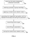
figure 4 , thesecond circuitry 20 is configured to carry out at least five operations 200-240. - The
first operation 200 consists in receiving information designating a functionality of the controlled electronic equipment 1' that is selected amongst its plurality of controllable functionalities. - The functionality may be selected via a dedicated application running on the
user device 2, and more precisely on itssecond circuitry 20, and controllable by the user by means of auser interface 22 connected to thesecond circuitry 20. - In a non-illustrated embodiment, the dedicated application could run on the electronic equipment 1' that is used by the user of the
user device 2 and paired to the latter. In the embodiment, the user selects the functionality via the dedicated application running on his electronic equipment 1' and the latter transmits the information designating the selected functionality to the paireduser device 2, via itscommunication interface 14. The transmission of this information may be carried out by means of a short-range wireless communication, for instance. Such a short-range wireless communication may be a Bluetooth communication, for instance. But this is a non-limiting example, and other types of short-range wireless communications are possible, and notably NFC, RFID, ZigBee, and Wi-Fi Direct. It could be also possible to couple theuser device 2 with the electronic equipment 1' by means of a cable (possibly of the USB type). - The
second operation 210 carried out by thesecond circuitry 20 consists in receiving a plurality of recordings of a same group of at least one user input for the selected functionality. - Each recording of a group of at least one user input may be carried out by at least one sensor via the above-mentioned dedicated application. For instance, the
user device 2 may comprise each sensor 23-26, and in this embodiment each recording starts when the user handles hisuser device 2 and carries out a user input that is recorded by at least one sensor 23-26. It should be recognized that the disclosure is not limited in this regard, and each sensor could be provided in an external device communicatively coupled (or intended to be coupled) to theuser device 2. Such an external device may be the electronic equipment 1' or another device used by the user (for instance a virtual assistant). In the embodiment, each recording starts when the user handles or uses his external device and carries out a user input that is recorded by at least one sensor. - The
second circuitry 20 of theuser device 2 may be configured to control the sensor(s) 23-26 to capture the plurality of recordings of each group of user input(s). - When the recordings are only captured but not processed by the electronic equipment 1', the data defining them are transmitted to the
user device 2 by itscommunication interface 14. - When the recordings are captured and processed by the
second circuitry 20, thethird operation 220 carried out by thissecond circuitry 20 consists in applying a trained neural network model on the received plurality of recordings to recognize an input pattern. - When the recordings are captured and processed by the
second circuitry 20, thefourth operation 230 carried out by thissecond circuitry 20 consists in associating the recognized input pattern with the selected functionality, and in storing this association in a memory. - When the recordings are captured and processed by the
second circuitry 20, thefifth operation 240 carried out by thissecond circuitry 20 consists in transmitting a control signal to the controlled electronic equipment 1' to control this selected functionality each time the user provides the associated recognized input pattern to theuser device 2. - In other words, when the user carries out user input(s) with his
user device 2, these user inputs are recorded by the sensor(s) 23-26 and this recording is compared to the recognized input pattern(s) stored in the association(s), and if this recording matches with a recognized input pattern then thesecond circuitry 20 transmits a control signal to the controlled electronic equipment 1' to control the selected functionality associated with this recognized input pattern. - So, the invention allows a user to programmably customize a part of the
user interface 22 of hisuser device 2 that allows recognition of a user pattern concerning a controllable functionality of the electronic equipment 1'. Moreover, since each recognized input pattern is based on several group recordings, the input pattern recognition task of theuser device 2 is facilitated, and therefore the number of input pattern recognition errors with thisuser device 2 is notably decreased. - Every option described above and concerning the
first circuitry 4 concerns also thesecond circuitry 20, and notably the ones concerning the third 120, fourth 130, sixth 150 and seventh 160 operations. So, thethird operation 220 carried out by thesecond circuitry 20 is equivalent to thethird operation 120 carried out by thefirst circuitry 4, thefourth operation 230 carried out by thesecond circuitry 20 is equivalent to thefourth operation 130 carried out by thefirst circuitry 4, asixth operation 250 carried out by thesecond circuitry 20 is equivalent to the sixth operation 150 (transmission of association information to the server 3) carried out by thefirst circuitry 4, and aseventh operation 260 carried out by thesecond circuitry 20 is equivalent to the seventh operation 160 (training the trained neural network model based on newly received user input) carried out by thefirst circuitry 4. - In still another embodiment illustrated in
figures 1 and3 , theserver 3 may comprise amemory 29 and athird circuitry 30. Thisthird circuitry 30 is configured to carry out five operations 300-340 as illustrated infigure 5 . - The
first operation 300 consists in receiving at least one recognized input pattern associated with a functionality of anelectronic equipment 1 or 1' offering a plurality of controllable functionalities. - The
second operation 310 carried out by thethird circuitry 30 consists in storing this received recognized input pattern in association with the electronic equipment functionality in thememory 29. - The
third operation 320 carried out by thethird circuitry 30 consists in receiving a request including an input criterion from a device different from the concernedelectronic equipment 1 or 1'. This device may be another electronic equipment different from theelectronic equipment 1, or a user device different from theuser device 2 paired with theelectronic equipment 1 or 1'. - The
fourth operation 330 carried out by thethird circuitry 30 consists in selecting a recognized input pattern into thememory 29 based on this received input criterion. - The
fifth operation 340 carried out by thethird circuitry 30 consists in transmitting this selected recognized input pattern to the requesting device. - For instance, the input criterion may be chosen from a group comprising a selection of a recognized input pattern associated to a functionality of the concerned electronic equipment, a selection of a functionality of the concerned electronic equipment, and a selection of a filter criterion including a complexity level of an input pattern associated to a functionality of the concerned electronic equipment.
Claims (20)
- An electronic equipment, comprising:
circuitry configured to:receive information designating a functionality selected amongst a plurality of controllable functionalities,receive a plurality of recordings of a same group of at least one user input for said selected functionality,apply a trained neural network model on said received plurality of recordings to recognize an input pattern,associate said recognized input pattern with said selected functionality, and store said association in a memory, andcontrol said selected functionality based on said stored association. - The electronic equipment according to claim 1, wherein said circuitry is further configured to:generate a distribution of at least one user input of said input pattern based on said plurality of recordings, anddetermine a variability of each user input of said recordings based on said generated distribution.
- The electronic equipment according to claim 2, wherein said circuitry is further configured to recognize an input pattern when each determined variability of the corresponding user input is smaller than a threshold value.
- The electronic equipment according to claim 2, wherein said circuitry is further configured to set said input pattern as a password for authentication of a user of said electronic equipment when said determined variability is smaller than a threshold value, and to associate said user with said input pattern.
- The electronic equipment according to claim 2, wherein said circuitry is further configured to request for additional recordings of user input(s) for said input pattern when said determined variability associated with at least one user input of previously received recordings is larger than a threshold value.
- The electronic equipment according to claim 1, wherein said circuitry is further configured to:receive another plurality of recordings for said selected functionality,apply said trained neural network model on said other received plurality of recordings to recognize another input pattern,associate said recognized input pattern and other input pattern with said selected functionality, andcontrol said selected functionality based on said input pattern or said other input pattern.
- The electronic equipment according to claim 1, wherein said circuitry is further configured to update an association of said selected functionality with a default input pattern with a recognized input pattern.
- The electronic equipment according to claim 1, wherein said circuitry is further configured to:execute an input pattern recognition process on a user input of said input pattern subsequent to said association, andcontrol execution of said selected functionality or authentication of a user associated with said input pattern, based on the execution of said pattern recognition process.
- The electronic equipment according to claim 1, wherein said circuitry is further configured to:receive a user input of said recognized input pattern to control said selected functionality after it has been associated with said recognized input pattern, andtrain said trained neural network model based on said received user input as a learning input to said trained neural network model.
- The electronic equipment according to claim 1, wherein said input pattern includes at least one of a user action on said electronic equipment, a user gesture associated with said electronic equipment, a sequence of user actions on said electronic equipment, and a sequence of user gestures associated with said electronic equipment.
- The electronic equipment according to claim 1, further comprising at least one sensor, and wherein said circuitry is further configured to control said sensor to capture said plurality of recordings of said group of user input(s).
- The electronic equipment according to claim 1, wherein said circuitry is further configured to receive said plurality of recordings of said input pattern from an external device communicatively coupled with said electronic equipment and comprising at least one sensor arranged for capturing said plurality of recordings.
- The electronic equipment according to claim 1, wherein each controllable functionality of the plurality of controllable functionalities is chosen from a group comprising a locking/unlocking of said electronic equipment, a start of use of said electronic equipment, a stop of use of the electronic equipment 1, a communication of said electronic equipment with an external device, a control of a heating element of said electronic equipment, an opening/closing of a shutter controlling access to a chamber of said electronic equipment, and a cleaning of said heating element.
- The electronic equipment according to claim 1, wherein said circuitry is further configured to control said trained neural network model to:determine a complexity level of an input pattern under recognition based on a set of criteria, andassociate said input pattern to said selected functionality when said determined complexity level is greater than a first threshold complexity, said trained neural network model being trained based on said set of criteria and said first threshold complexity.
- The electronic equipment according to claim 14, wherein said circuitry is further configured to control said trained neural network model to reject said input pattern when said determined complexity level is greater than a second threshold complexity that is greater than said first threshold complexity.
- The electronic equipment according to claim 1, wherein said circuitry is further configured to trigger transmission of information defining said association between said recognized input pattern and said selected functionality to a communication equipment for backup storage of said transmitted information.
- The electronic equipment according to claim 1, wherein the electronic equipment is any one of a vaping device, an aerosol generation device, an electronic cigarette, or a tobacco and/or nicotine delivery device.
- A device, comprising:
circuitry configured to:receive information designating a selected functionality of a controlled electronic equipment offering a plurality of controllable functionalities,receive a plurality of recordings of user input(s) for said selected functionality,apply a trained neural network model on said received plurality of recordings to recognize an input pattern,associate said recognized input pattern with said selected functionality, and store said association in a memory, andtransmit a control signal to said controlled electronic equipment to control said selected functionality each time a user provides said recognized input pattern to said device. - A server, comprising:a memory, andcircuitry configured to:receive at least one recognized input pattern associated with a functionality of an electronic equipment offering a plurality of controllable functionalities,store said received recognized input pattern in association with said electronic equipment functionality in said memory,receive a request including an input criterion from a device different from said electronic equipment,select a recognized input pattern into said memory based on said received input criterion, andtransmit said selected recognized input pattern to said device.
- The server according to claim 19, wherein said input criterion is chosen from a group comprising a selection of a recognized input pattern associated to a functionality of said electronic equipment, a selection of a functionality of said electronic equipment, and a selection of a filter criterion including a complexity level of an input pattern associated to a functionality of said electronic equipment.
Applications Claiming Priority (1)
| Application Number | Priority Date | Filing Date | Title |
|---|---|---|---|
| US17/690,370 US11526686B1 (en) | 2022-03-09 | 2022-03-09 | Programmable customization of a user interface of an electronic equipment |
Publications (4)
| Publication Number | Publication Date |
|---|---|
| EP4242882A2 true EP4242882A2 (en) | 2023-09-13 |
| EP4242882A3 EP4242882A3 (en) | 2023-11-01 |
| EP4242882C0 EP4242882C0 (en) | 2025-02-19 |
| EP4242882B1 EP4242882B1 (en) | 2025-02-19 |
Family
ID=84426739
Family Applications (1)
| Application Number | Title | Priority Date | Filing Date |
|---|---|---|---|
| EP23160380.4A Active EP4242882B1 (en) | 2022-03-09 | 2023-03-07 | Programmable customization of a user interface of an electronic equipment |
Country Status (6)
| Country | Link |
|---|---|
| US (2) | US11526686B1 (en) |
| EP (1) | EP4242882B1 (en) |
| JP (1) | JP7355956B2 (en) |
| KR (1) | KR102738811B1 (en) |
| PL (1) | PL4242882T3 (en) |
| WO (1) | WO2023170040A1 (en) |
Citations (1)
| Publication number | Priority date | Publication date | Assignee | Title |
|---|---|---|---|---|
| US10500600B2 (en) | 2014-12-09 | 2019-12-10 | Rai Strategic Holdings, Inc. | Gesture recognition user interface for an aerosol delivery device |
Family Cites Families (9)
| Publication number | Priority date | Publication date | Assignee | Title |
|---|---|---|---|---|
| DE102007016408A1 (en) * | 2007-03-26 | 2008-10-02 | Ident Technology Ag | Mobile communication device and input device therefor |
| KR101511381B1 (en) * | 2008-07-04 | 2015-04-10 | 엘지전자 주식회사 | User Authentication Device and Method |
| US9015093B1 (en) * | 2010-10-26 | 2015-04-21 | Michael Lamport Commons | Intelligent control with hierarchical stacked neural networks |
| US11696604B2 (en) * | 2014-03-13 | 2023-07-11 | Rai Strategic Holdings, Inc. | Aerosol delivery device and related method and computer program product for controlling an aerosol delivery device based on input characteristics |
| US10222868B2 (en) * | 2014-06-02 | 2019-03-05 | Samsung Electronics Co., Ltd. | Wearable device and control method using gestures |
| US11972367B2 (en) * | 2017-07-11 | 2024-04-30 | Sap Se | Pattern recognition to detect erroneous data |
| CN112602080B (en) * | 2018-06-27 | 2025-09-02 | 尤尔实验室有限公司 | Connected evaporator unit system |
| PL3932225T3 (en) * | 2020-06-30 | 2022-10-03 | Philip Morris Products S.A. | AEROSOL DEVICE PROVIDING STATUS INQUIRY INITIATED BY GESTURES |
| JP2023536828A (en) * | 2020-07-28 | 2023-08-30 | ジェイティー インターナショナル エスエイ | Method of operating an aerosol generator |
-
2022
- 2022-03-09 US US17/690,370 patent/US11526686B1/en active Active
- 2022-11-09 US US18/053,843 patent/US20230289403A1/en not_active Abandoned
-
2023
- 2023-03-07 PL PL23160380.4T patent/PL4242882T3/en unknown
- 2023-03-07 EP EP23160380.4A patent/EP4242882B1/en active Active
- 2023-03-07 KR KR1020247028620A patent/KR102738811B1/en active Active
- 2023-03-07 WO PCT/EP2023/055701 patent/WO2023170040A1/en not_active Ceased
- 2023-03-08 JP JP2023035249A patent/JP7355956B2/en active Active
Patent Citations (1)
| Publication number | Priority date | Publication date | Assignee | Title |
|---|---|---|---|---|
| US10500600B2 (en) | 2014-12-09 | 2019-12-10 | Rai Strategic Holdings, Inc. | Gesture recognition user interface for an aerosol delivery device |
Also Published As
| Publication number | Publication date |
|---|---|
| EP4242882C0 (en) | 2025-02-19 |
| KR20240134055A (en) | 2024-09-05 |
| EP4242882B1 (en) | 2025-02-19 |
| EP4242882A3 (en) | 2023-11-01 |
| WO2023170040A1 (en) | 2023-09-14 |
| JP7355956B2 (en) | 2023-10-03 |
| US11526686B1 (en) | 2022-12-13 |
| JP2023133221A (en) | 2023-09-22 |
| KR102738811B1 (en) | 2024-12-04 |
| US20230289403A1 (en) | 2023-09-14 |
| PL4242882T3 (en) | 2025-06-23 |
Similar Documents
| Publication | Publication Date | Title |
|---|---|---|
| JP6317400B2 (en) | Integration of sensory functions into social networking services and social networking applications | |
| US12438738B2 (en) | Electronic device and method for sharing data using blockchain network | |
| TWI639114B (en) | Electronic device with a function of smart voice service and method of adjusting output sound | |
| CN105706416B (en) | User equipment and computer readable medium for network access | |
| CN108076052A (en) | Authorization server, non-transitory computer-readable medium and delegation system | |
| TWI574256B (en) | Interactive beat effect system and method for processing interactive beat effect | |
| CN117056892A (en) | Secure authorization for access to private data in virtual reality | |
| CN108156155B (en) | Wireless network-based biometric authentication system, mobile device and method | |
| CN104851440B (en) | A kind of music shuffle method and intelligent sound box | |
| US20140115492A1 (en) | System and method for transposing an external user interface on a mobile device | |
| CN114331448B (en) | Biometric information verification method and equipment | |
| WO2016075792A1 (en) | Information processing apparatus, control method, and program | |
| CN113168435A (en) | Non-contact user authentication method | |
| US20230005458A1 (en) | Parameter Inference Method, Parameter Inference System, and Parameter Inference Program | |
| CN113287791A (en) | Unlocking method, device and system of electronic atomization device, authentication end and battery rod | |
| CN114146426A (en) | Control method and device for game in secret room, computer equipment and storage medium | |
| CN113596030B (en) | Equipment distribution methods, devices, storage media and electronic equipment | |
| EP4242882B1 (en) | Programmable customization of a user interface of an electronic equipment | |
| CN105116862B (en) | Household electric appliance control method, device and wearable device based on biometric information verification | |
| JP6385100B2 (en) | Information processing apparatus, information processing system, information processing apparatus control method, and computer program | |
| WO2022246925A1 (en) | Anti-counterfeiting method, apparatus, and system for atomizer assembly, authentication terminal, and battery stick | |
| CN110934345B (en) | Electronic device, registration and interaction system, and registration and interaction method | |
| JP2019041362A (en) | Microphone cooperation device | |
| KR20230034786A (en) | Electronic apparatus and operaintg method thereof | |
| KR20240036656A (en) | Information processing methods, aerosol generation systems and programs |
Legal Events
| Date | Code | Title | Description |
|---|---|---|---|
| PUAI | Public reference made under article 153(3) epc to a published international application that has entered the european phase |
Free format text: ORIGINAL CODE: 0009012 |
|
| STAA | Information on the status of an ep patent application or granted ep patent |
Free format text: STATUS: THE APPLICATION HAS BEEN PUBLISHED |
|
| AK | Designated contracting states |
Kind code of ref document: A2 Designated state(s): AL AT BE BG CH CY CZ DE DK EE ES FI FR GB GR HR HU IE IS IT LI LT LU LV MC ME MK MT NL NO PL PT RO RS SE SI SK SM TR |
|
| PUAL | Search report despatched |
Free format text: ORIGINAL CODE: 0009013 |
|
| AK | Designated contracting states |
Kind code of ref document: A3 Designated state(s): AL AT BE BG CH CY CZ DE DK EE ES FI FR GB GR HR HU IE IS IT LI LT LU LV MC ME MK MT NL NO PL PT RO RS SE SI SK SM TR |
|
| RIC1 | Information provided on ipc code assigned before grant |
Ipc: H04L 9/40 20220101ALI20230926BHEP Ipc: A24F 40/51 20200101ALI20230926BHEP Ipc: G06F 18/214 20230101ALI20230926BHEP Ipc: G06F 18/21 20230101ALI20230926BHEP Ipc: G06F 18/00 20230101AFI20230926BHEP |
|
| STAA | Information on the status of an ep patent application or granted ep patent |
Free format text: STATUS: REQUEST FOR EXAMINATION WAS MADE |
|
| 17P | Request for examination filed |
Effective date: 20240411 |
|
| RBV | Designated contracting states (corrected) |
Designated state(s): AL AT BE BG CH CY CZ DE DK EE ES FI FR GB GR HR HU IE IS IT LI LT LU LV MC ME MK MT NL NO PL PT RO RS SE SI SK SM TR |
|
| STAA | Information on the status of an ep patent application or granted ep patent |
Free format text: STATUS: EXAMINATION IS IN PROGRESS |
|
| 17Q | First examination report despatched |
Effective date: 20240531 |
|
| REG | Reference to a national code |
Ref legal event code: R079 Ipc: G06N0003080000 Ref country code: DE Ref legal event code: R079 Ref document number: 602023002050 Country of ref document: DE Free format text: PREVIOUS MAIN CLASS: G06F0018000000 Ipc: G06N0003080000 |
|
| GRAP | Despatch of communication of intention to grant a patent |
Free format text: ORIGINAL CODE: EPIDOSNIGR1 |
|
| STAA | Information on the status of an ep patent application or granted ep patent |
Free format text: STATUS: GRANT OF PATENT IS INTENDED |
|
| RIC1 | Information provided on ipc code assigned before grant |
Ipc: H04L 9/40 20220101ALI20240903BHEP Ipc: G06F 18/214 20230101ALI20240903BHEP Ipc: G06F 18/21 20230101ALI20240903BHEP Ipc: G06N 3/08 20230101AFI20240903BHEP |
|
| INTG | Intention to grant announced |
Effective date: 20240916 |
|
| GRAS | Grant fee paid |
Free format text: ORIGINAL CODE: EPIDOSNIGR3 |
|
| GRAA | (expected) grant |
Free format text: ORIGINAL CODE: 0009210 |
|
| STAA | Information on the status of an ep patent application or granted ep patent |
Free format text: STATUS: THE PATENT HAS BEEN GRANTED |
|
| AK | Designated contracting states |
Kind code of ref document: B1 Designated state(s): AL AT BE BG CH CY CZ DE DK EE ES FI FR GB GR HR HU IE IS IT LI LT LU LV MC ME MK MT NL NO PL PT RO RS SE SI SK SM TR |
|
| REG | Reference to a national code |
Ref country code: GB Ref legal event code: FG4D |
|
| REG | Reference to a national code |
Ref country code: CH Ref legal event code: EP |
|
| REG | Reference to a national code |
Ref country code: IE Ref legal event code: FG4D |
|
| REG | Reference to a national code |
Ref country code: DE Ref legal event code: R096 Ref document number: 602023002050 Country of ref document: DE |
|
| U01 | Request for unitary effect filed |
Effective date: 20250318 |
|
| U07 | Unitary effect registered |
Designated state(s): AT BE BG DE DK EE FI FR IT LT LU LV MT NL PT RO SE SI Effective date: 20250325 |
|
| PGFP | Annual fee paid to national office [announced via postgrant information from national office to epo] |
Ref country code: AT Payment date: 20250417 Year of fee payment: 3 |
|
| U20 | Renewal fee for the european patent with unitary effect paid |
Year of fee payment: 3 Effective date: 20250425 |
|
| PG25 | Lapsed in a contracting state [announced via postgrant information from national office to epo] |
Ref country code: RS Free format text: LAPSE BECAUSE OF FAILURE TO SUBMIT A TRANSLATION OF THE DESCRIPTION OR TO PAY THE FEE WITHIN THE PRESCRIBED TIME-LIMIT Effective date: 20250519 |
|
| PG25 | Lapsed in a contracting state [announced via postgrant information from national office to epo] |
Ref country code: ES Free format text: LAPSE BECAUSE OF FAILURE TO SUBMIT A TRANSLATION OF THE DESCRIPTION OR TO PAY THE FEE WITHIN THE PRESCRIBED TIME-LIMIT Effective date: 20250219 |
|
| PG25 | Lapsed in a contracting state [announced via postgrant information from national office to epo] |
Ref country code: IS Free format text: LAPSE BECAUSE OF FAILURE TO SUBMIT A TRANSLATION OF THE DESCRIPTION OR TO PAY THE FEE WITHIN THE PRESCRIBED TIME-LIMIT Effective date: 20250619 Ref country code: NO Free format text: LAPSE BECAUSE OF FAILURE TO SUBMIT A TRANSLATION OF THE DESCRIPTION OR TO PAY THE FEE WITHIN THE PRESCRIBED TIME-LIMIT Effective date: 20250519 |
|
| PG25 | Lapsed in a contracting state [announced via postgrant information from national office to epo] |
Ref country code: HR Free format text: LAPSE BECAUSE OF FAILURE TO SUBMIT A TRANSLATION OF THE DESCRIPTION OR TO PAY THE FEE WITHIN THE PRESCRIBED TIME-LIMIT Effective date: 20250219 |
|
| PG25 | Lapsed in a contracting state [announced via postgrant information from national office to epo] |
Ref country code: GR Free format text: LAPSE BECAUSE OF FAILURE TO SUBMIT A TRANSLATION OF THE DESCRIPTION OR TO PAY THE FEE WITHIN THE PRESCRIBED TIME-LIMIT Effective date: 20250520 |
|
| PG25 | Lapsed in a contracting state [announced via postgrant information from national office to epo] |
Ref country code: SM Free format text: LAPSE BECAUSE OF FAILURE TO SUBMIT A TRANSLATION OF THE DESCRIPTION OR TO PAY THE FEE WITHIN THE PRESCRIBED TIME-LIMIT Effective date: 20250219 |
|
| PG25 | Lapsed in a contracting state [announced via postgrant information from national office to epo] |
Ref country code: CZ Free format text: LAPSE BECAUSE OF FAILURE TO SUBMIT A TRANSLATION OF THE DESCRIPTION OR TO PAY THE FEE WITHIN THE PRESCRIBED TIME-LIMIT Effective date: 20250219 |
|
| PG25 | Lapsed in a contracting state [announced via postgrant information from national office to epo] |
Ref country code: SK Free format text: LAPSE BECAUSE OF FAILURE TO SUBMIT A TRANSLATION OF THE DESCRIPTION OR TO PAY THE FEE WITHIN THE PRESCRIBED TIME-LIMIT Effective date: 20250219 |
|
| PG25 | Lapsed in a contracting state [announced via postgrant information from national office to epo] |
Ref country code: MC Free format text: LAPSE BECAUSE OF FAILURE TO SUBMIT A TRANSLATION OF THE DESCRIPTION OR TO PAY THE FEE WITHIN THE PRESCRIBED TIME-LIMIT Effective date: 20250219 |
|
| PLBE | No opposition filed within time limit |
Free format text: ORIGINAL CODE: 0009261 |
|
| STAA | Information on the status of an ep patent application or granted ep patent |
Free format text: STATUS: NO OPPOSITION FILED WITHIN TIME LIMIT |
|
| REG | Reference to a national code |
Ref country code: CH Ref legal event code: L10 Free format text: ST27 STATUS EVENT CODE: U-0-0-L10-L00 (AS PROVIDED BY THE NATIONAL OFFICE) Effective date: 20251231 |
|
| PG25 | Lapsed in a contracting state [announced via postgrant information from national office to epo] |
Ref country code: IE Free format text: LAPSE BECAUSE OF NON-PAYMENT OF DUE FEES Effective date: 20250307 |
|
| 26N | No opposition filed |
Effective date: 20251120 |
|
| REG | Reference to a national code |
Ref country code: CH Ref legal event code: U11 Free format text: ST27 STATUS EVENT CODE: U-0-0-U10-U11 (AS PROVIDED BY THE NATIONAL OFFICE) Effective date: 20260401 |
|
| PGFP | Annual fee paid to national office [announced via postgrant information from national office to epo] |
Ref country code: PL Payment date: 20260302 Year of fee payment: 4 |
|
| U20 | Renewal fee for the european patent with unitary effect paid |
Year of fee payment: 4 Effective date: 20260326 |