EP4242759A1 - Improved electrospindle - Google Patents
Improved electrospindle Download PDFInfo
- Publication number
- EP4242759A1 EP4242759A1 EP23159951.5A EP23159951A EP4242759A1 EP 4242759 A1 EP4242759 A1 EP 4242759A1 EP 23159951 A EP23159951 A EP 23159951A EP 4242759 A1 EP4242759 A1 EP 4242759A1
- Authority
- EP
- European Patent Office
- Prior art keywords
- motor
- ventilation device
- temperature
- value
- electrospindle
- Prior art date
- Legal status (The legal status is an assumption and is not a legal conclusion. Google has not performed a legal analysis and makes no representation as to the accuracy of the status listed.)
- Pending
Links
Images


Classifications
-
- G—PHYSICS
- G05—CONTROLLING; REGULATING
- G05B—CONTROL OR REGULATING SYSTEMS IN GENERAL; FUNCTIONAL ELEMENTS OF SUCH SYSTEMS; MONITORING OR TESTING ARRANGEMENTS FOR SUCH SYSTEMS OR ELEMENTS
- G05B19/00—Program-control systems
- G05B19/02—Program-control systems electric
- G05B19/18—Numerical control [NC], i.e. automatically operating machines, in particular machine tools, e.g. in a manufacturing environment, so as to execute positioning, movement or co-ordinated operations by means of program data in numerical form
- G05B19/404—Numerical control [NC], i.e. automatically operating machines, in particular machine tools, e.g. in a manufacturing environment, so as to execute positioning, movement or co-ordinated operations by means of program data in numerical form characterised by control arrangements for compensation, e.g. for backlash, overshoot, tool offset, tool wear, temperature, machine construction errors, load, inertia
-
- B—PERFORMING OPERATIONS; TRANSPORTING
- B23—MACHINE TOOLS; METAL-WORKING NOT OTHERWISE PROVIDED FOR
- B23Q—DETAILS, COMPONENTS, OR ACCESSORIES FOR MACHINE TOOLS, e.g. ARRANGEMENTS FOR COPYING OR CONTROLLING; MACHINE TOOLS IN GENERAL CHARACTERISED BY THE CONSTRUCTION OF PARTICULAR DETAILS OR COMPONENTS; COMBINATIONS OR ASSOCIATIONS OF METAL-WORKING MACHINES, NOT DIRECTED TO A PARTICULAR RESULT
- B23Q1/00—Members which are comprised in the general build-up of a form of machine, particularly relatively large fixed members
- B23Q1/70—Stationary or movable members for carrying working-spindles for attachment of tools or work
-
- B—PERFORMING OPERATIONS; TRANSPORTING
- B23—MACHINE TOOLS; METAL-WORKING NOT OTHERWISE PROVIDED FOR
- B23Q—DETAILS, COMPONENTS, OR ACCESSORIES FOR MACHINE TOOLS, e.g. ARRANGEMENTS FOR COPYING OR CONTROLLING; MACHINE TOOLS IN GENERAL CHARACTERISED BY THE CONSTRUCTION OF PARTICULAR DETAILS OR COMPONENTS; COMBINATIONS OR ASSOCIATIONS OF METAL-WORKING MACHINES, NOT DIRECTED TO A PARTICULAR RESULT
- B23Q11/00—Accessories fitted to machine tools for keeping tools or parts of the machine in good working condition or for cooling work; Safety devices specially combined with or arranged in, or specially adapted for use in connection with, machine tools
- B23Q11/12—Arrangements for cooling or lubricating parts of the machine
- B23Q11/126—Arrangements for cooling or lubricating parts of the machine for cooling only
- B23Q11/127—Arrangements for cooling or lubricating parts of the machine for cooling only for cooling motors or spindles
-
- B—PERFORMING OPERATIONS; TRANSPORTING
- B23—MACHINE TOOLS; METAL-WORKING NOT OTHERWISE PROVIDED FOR
- B23Q—DETAILS, COMPONENTS, OR ACCESSORIES FOR MACHINE TOOLS, e.g. ARRANGEMENTS FOR COPYING OR CONTROLLING; MACHINE TOOLS IN GENERAL CHARACTERISED BY THE CONSTRUCTION OF PARTICULAR DETAILS OR COMPONENTS; COMBINATIONS OR ASSOCIATIONS OF METAL-WORKING MACHINES, NOT DIRECTED TO A PARTICULAR RESULT
- B23Q17/00—Arrangements for observing, indicating or measuring on machine tools
- B23Q17/09—Arrangements for observing, indicating or measuring on machine tools for indicating or measuring cutting pressure or for determining cutting-tool condition, e.g. cutting ability, load on tool
- B23Q17/0952—Arrangements for observing, indicating or measuring on machine tools for indicating or measuring cutting pressure or for determining cutting-tool condition, e.g. cutting ability, load on tool during machining
- B23Q17/0985—Arrangements for observing, indicating or measuring on machine tools for indicating or measuring cutting pressure or for determining cutting-tool condition, e.g. cutting ability, load on tool during machining by measuring temperature
-
- G—PHYSICS
- G05—CONTROLLING; REGULATING
- G05B—CONTROL OR REGULATING SYSTEMS IN GENERAL; FUNCTIONAL ELEMENTS OF SUCH SYSTEMS; MONITORING OR TESTING ARRANGEMENTS FOR SUCH SYSTEMS OR ELEMENTS
- G05B19/00—Program-control systems
- G05B19/02—Program-control systems electric
- G05B19/18—Numerical control [NC], i.e. automatically operating machines, in particular machine tools, e.g. in a manufacturing environment, so as to execute positioning, movement or co-ordinated operations by means of program data in numerical form
- G05B19/406—Numerical control [NC], i.e. automatically operating machines, in particular machine tools, e.g. in a manufacturing environment, so as to execute positioning, movement or co-ordinated operations by means of program data in numerical form characterised by monitoring or safety
-
- G—PHYSICS
- G05—CONTROLLING; REGULATING
- G05B—CONTROL OR REGULATING SYSTEMS IN GENERAL; FUNCTIONAL ELEMENTS OF SUCH SYSTEMS; MONITORING OR TESTING ARRANGEMENTS FOR SUCH SYSTEMS OR ELEMENTS
- G05B2219/00—Program-control systems
- G05B2219/30—Nc systems
- G05B2219/37—Measurements
- G05B2219/37429—Temperature of motor
-
- G—PHYSICS
- G05—CONTROLLING; REGULATING
- G05B—CONTROL OR REGULATING SYSTEMS IN GENERAL; FUNCTIONAL ELEMENTS OF SUCH SYSTEMS; MONITORING OR TESTING ARRANGEMENTS FOR SUCH SYSTEMS OR ELEMENTS
- G05B2219/00—Program-control systems
- G05B2219/30—Nc systems
- G05B2219/49—Nc machine tool, till multiple
- G05B2219/49052—Accessory, coolant
Definitions
- the present invention relates to an improved electrospindle.
- the present invention relates to an electrospindle designed to adjust the velocity of a fan of at least one ventilation device (included in said electrospindle) in order to cool the electric motor of said electrospindle.
- a machine tool comprises a machining head provided with one or more electrospindles.
- An electrospindle comprises a shaft having a longitudinal axis and an electric motor for rotating said shaft about said longitudinal axis.
- the electric motor comprises a stator and a rotor and said shaft is arranged inside said rotor and integral with said rotor.
- an electrospindle has a first end portion, on which a respective tool can be positioned and a second end portion, opposite to said first end portion.
- the first end portion can be coupled directly to the tool or provided with a support/tool holder that can be coupled with the tool.
- the tool is chosen based on the machining to be performed. For example, if a hole needs to be drilled, the tool can be a drill bit.
- the electric motor causes the rotation of the shaft, and the rotation of the shaft causes rotation of the tool.
- the temperature of the electric motor rises as a workpiece is being machined.
- the temperature increases significantly when the workpiece is made of a hard material, such as marble, glass, stone, etc.
- the electrospindle can be provided with a ventilation device to emit an air jet.
- a first example of a known type of electrospindle comprises a single ventilation device comprising at least one blade and a motor for rotating said blade.
- the air jet emitted by this ventilation device must dissipate a quantity of heat produced by the electric motor of the electrospindle, so that the temperature of the electric motor is compatible with the temperature of the materials of which the electrospindle is made of, and in particular with the temperature referred to the insulating materials present inside the stator, as well as with the temperature of the bearings that support the rotor.
- a disadvantage is given by the fact that it is not possible to adjust the velocity of the motor and consequently of the blade based on the temperature of the electric motor of the electrospindle.
- a further disadvantage is that the ventilation device generates a high noise level while in use.
- the number of revolutions of the motor of the ventilation device is equal to the maximum number of revolutions available, i.e. the maximum number of revolutions associated with the motor of said ventilation device.
- the aim of the present invention is to overcome said disadvantages, providing an improved electrospindle comprising a casing and at least one ventilation device provided with one or more blades and a motor for rotating said one or more blades, in which said electrospindle is designed to adjust the velocity of said motor and, therefore, the velocity of said one or more blades, in order to cool the electric motor of said electrospindle according to the temperature detected on said electrospindle.
- a second aim of the invention is to provide an improved electrospindle for cooling the electric motor, with a reduced noise level compared to the noise level of a known type of electrospindle.
- a third aim of the invention is to provide an improved electrospindle, in which said at least one ventilation device emits an air jet inside the casing, towards a portion of said casing arranged around the electric motor of the electrospindle.
- the electric motor of the electrospindle comprises a stator and a rotor
- the rotation of said electric motor i.e., the rotation of the rotor
- the direction of said air jet is parallel to the longitudinal axis of said shaft.
- Further aim of the invention is to provide a reliable electrospindle having a simple structure and a low production cost.
- an electrospindle comprising:
- Said electrospindle includes:
- Said electrospindle also comprises:
- Said first velocity value associated with said motor of said motor E of said first ventilation device F and stored in said storage means 6 is a predetermined velocity value V REF .
- Said predetermined velocity value V REF it is a fixed value.
- Said fixed value can be a value chosen regardless of the temperature of the electric motor of the electrospindle, or a value depending on the temperature of the electrospindle electric motor.
- said electric motor 2 comprises a stator 21 and a rotor 22.
- the rotor 22 is arranged inside said stator 21.
- said shaft 3 is arranged at least partially inside said electric motor 2.
- the shaft 3 is arranged inside the rotor 22 of the electric motor 2.
- the shaft 3 is integral with the electric motor 2 (in particular with the rotor 22 of the electric motor 2) so that the rotation of said electric motor 2 causes the rotation of said shaft 3.
- the rotation of said shaft 3 causes the rotation of the tool 7 mounted on the electrospindle.
- said first detecting device can be arranged on a portion of the casing 11 of the electrospindle at, or near said electric motor 2.
- said first detecting device 4 is a first temperature sensor.
- the air jet generated by said first ventilation device F is directed inside a portion of said casing 1 arranged around the electric motor 2 of the electrospindle.
- the electrospindle comprises a duct for joining the first ventilation device F to the electric motor 2 of the electrospindle, so that the air jet generated by said first ventilation device F easily reaches said electric motor.
- said duct has an axis, which coincides with the longitudinal axis A of shaft 3 of the electrospindle.
- the motor E for rotating the blade B is an electric motor, different from the electric motor of the electrospindle.
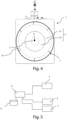
- Figures 2 and 3 show the second end wall 1B of the electrospindle, wherein the first ventilation device F is positioned, respectively with a protection device S to protect said first ventilation device, and without said protection device S.
- said protective device S is a casing.
- said storage means 6 comprise a memory.
- said storage means are external to said control unit U.
- said storage means can be arranged inside said control unit, without departing from the scope of the invention.
- a first temperature threshold T S 1 associated with said electric motor 2 and a first velocity value associated with the motor E of the first ventilation device F are stored in said storage means.
- the control unit U acquires temperature values T Mi associated with the electric motor 2 of the electrospindle (via the first temperature detecting device 4) over time, compares each of said temperature values T Mi with said first temperature threshold T S 1 , and sends a command signal to the motor E of the first ventilation device F, so that the velocity of said motor E is equal to said first velocity value when a temperature value T Mi is greater than said first temperature threshold T S 1 .
- further data can be stored in said storage means 6.
- the following data can be stored in said storage means: a reference ratio ⁇ T ref between a predetermined temperature difference T ref 2 - T ref1 and a predetermined time interval ⁇ t .
- control unit U can be configured to:
- the predetermined time interval ⁇ t used in the reference ratio ⁇ T ref stored in said storage means 6 is equal to each predetermined time interval, wherein a respective ratio ⁇ T is to be calculated.
- said first velocity value is a predetermined velocity value V REF , which is a fixed value
- said first velocity value is a dynamic value, i.e. a value that changes over time.
- the ventilation device F can further comprise detection means for detecting in at least one time instant t i a respective velocity value V Mi associated with the motor E of the first ventilation device F.
- Said control unit U can be configured to acquire each velocity value V Mi , associated with the motor E of said first ventilation device F to check whether the blade B rotates.
- control unit U be configured so as not to send any control signal to the motor E of the first ventilation device F if a temperature value T Mi associated with the electric motor 2 of the electrospindle is less than, or equal to said first temperature threshold T S 1 .
- said electrospindle preferably comprises:
- the first velocity value associated with the motor E of the ventilation device F and stored in said storage means 6 is a value, which depends on the temperature of said bearing 13.
- a second temperature threshold T S 2 associated with said bearing 13 is stored in said storage means 6.
- control unit U is connected to said second temperature sensing device 5 and configured to:
- said first velocity value is a dynamic value, i.e. a value that changes over time.
- a second velocity value associated with the electric motor E of the ventilation device F and dependent on the temperature of said electric motor 2 of said electrospindle is stored in said storage means 6.
- control unit U can be connected to said second temperature detecting device 5 and configured to:
- control unit U identifies the maximum velocity value v max between the velocity value v Ci calculated using the first formula, and the velocity value v M 2 i calculated using the second formula, and sends a control signal to the motor E of the first ventilation device F, so that the velocity of said motor E of said first ventilation device F is equal to said maximum velocity value v max .
- said bearing 13 is arranged on said first end wall 1A of said casing 11.
- said second sensing device is a second temperature sensor.
- control unit U can be configured not to send any control signal to said motor E of said first ventilation device F when said temperature value TC i associated with said bearing 13 is less than or equal to said second temperature threshold T S 2 .
- a third temperature threshold T S 3 can be stored in said storage means 6 and said control unit U can be configured to:
- Said third temperature threshold T S 3 is associated with said electric motor 2.
- said third temperature threshold T S 3 is a further temperature threshold associated with the electric motor 2 with respect to the first temperature threshold T S 1 mentioned above.
- said third temperature threshold T S 3 associated with the electric motor 2 is different from said first temperature threshold T S 1 associated with the electric motor 2.
- said third temperature threshold T S 3 is greater than said first temperature threshold T S 1 .
- a fourth temperature threshold T S 4 can be stored in said storage means 6 and said control unit U can be configured to:
- said fourth temperature threshold T S 4 is a further temperature threshold associated with the bearing 13 with respect to the second temperature threshold T S 2 mentioned above.
- said fourth temperature threshold T S 4 associated with the bearing 13 is different from said second temperature threshold T S 2 associated with bearing 13.
- said fourth temperature threshold T S 4 is greater than said second temperature threshold T S 2 .
- Figures 6 to 9 show a second embodiment of the electrospindle.
- said electrospindle comprises a plurality of ventilation devices for cooling the electric motor 2 of the electrospindle itself.
- said electrospindle comprises four ventilation devices: a first ventilation device F1, a second ventilation device F2, a third ventilation device F3, and a fourth ventilation device F4.
- Each ventilation device F1, F2, F3, F4 respectively comprises at least one blade B1, B2, B3, B4 and a motor E1, E2, E3, E4 for rotating said blade B1, B2, B3, B4.
- Each ventilation device F1, F2, F3, F4 is arranged on said second end wall 1B of said casing 1.
- the electrospindle comprises a respective protection device S1, S2, S3, S4 to protect each ventilation device F1,F2, F3, F4.
- each protection device S1, S2, S3, S4 is a respective carter.
- Said control unit U is configured to:
- control unit U is configured to send a number of command signals equal to the number of ventilation devices so that the velocity value of the respective motor of each ventilation device is equal to said first velocity value.
- the electrospindle comprises a plurality of ducts (not shown), in particular a respective duct for each ventilation device F1, F2, F3, F4, so that a respective air jet is emitted into a respective duct.
- the ducts of said plurality of ducts are arranged inside the casing in such a way that the engine is in a central position with respect to said ducts.
- the ducts allow cooling a portion of the casing 1 arranged around the electric motor 2 of the electrospindle.
- Each duct of said plurality of ducts has a respective axis, parallel to the longitudinal axis A of the shaft and each ventilation device F1, F2, F3, F4 is arranged along the axis of a respective duct.
- each duct has a first end and a second end.
- Each ventilation device can be arranged at said first end of a respective duct, while the second end of each duct is a free end.
- the control unit U is configured to send a respective command signal to each motor E1, E2, E3, E4 of the respective ventilation device F1, F2, F3, F4.
- control unit U is configured to send a plurality of command signals according to the number of ventilation devices F1, F2, F3, F4 included in the electrospindle.
- the present invention relates to a machining head comprising at least one electrospindle as described above with reference to the first embodiment or the second embodiment.
- the present invention also refers to a machine tool for machining parts, comprising:
- a first advantage of the improved electrospindle object of the invention is given by the possibility of adjusting the velocity of the motor of at least one ventilation device in order to cool the electric motor of the electrospindle according to the temperature associated with said electric motor, in which said temperature is detected by at least one temperature sensor installed on said electrospindle.
- a further advantage is given by the possibility of emitting an air jet inside the electrospindle casing, to cool a portion of said casing located inside the electric motor on the basis of the amount of heat to be dissipated, with a level of reduced noise.
Landscapes
- Engineering & Computer Science (AREA)
- Mechanical Engineering (AREA)
- Human Computer Interaction (AREA)
- Manufacturing & Machinery (AREA)
- Physics & Mathematics (AREA)
- General Physics & Mathematics (AREA)
- Automation & Control Theory (AREA)
Abstract
Description
- The present invention relates to an improved electrospindle.
- In particular, the present invention relates to an electrospindle designed to adjust the velocity of a fan of at least one ventilation device (included in said electrospindle) in order to cool the electric motor of said electrospindle.
- As is known, a machine tool comprises a machining head provided with one or more electrospindles.
- An electrospindle comprises a shaft having a longitudinal axis and an electric motor for rotating said shaft about said longitudinal axis.
- In particular, the electric motor comprises a stator and a rotor and said shaft is arranged inside said rotor and integral with said rotor.
- Furthermore, an electrospindle has a first end portion, on which a respective tool can be positioned and a second end portion, opposite to said first end portion.
- For machining a workpiece, the first end portion can be coupled directly to the tool or provided with a support/tool holder that can be coupled with the tool.
- The tool is chosen based on the machining to be performed. For example, if a hole needs to be drilled, the tool can be a drill bit.
- When an electrospindle is in use, the electric motor causes the rotation of the shaft, and the rotation of the shaft causes rotation of the tool.
- The temperature of the electric motor rises as a workpiece is being machined.
- In particular, the temperature increases significantly when the workpiece is made of a hard material, such as marble, glass, stone, etc.
- Consequently, the electric motor of the electrospindle should be cooled.
- To this end, the electrospindle can be provided with a ventilation device to emit an air jet.
- A first example of a known type of electrospindle comprises a single ventilation device comprising at least one blade and a motor for rotating said blade.
- The air jet emitted by this ventilation device must dissipate a quantity of heat produced by the electric motor of the electrospindle, so that the temperature of the electric motor is compatible with the temperature of the materials of which the electrospindle is made of, and in particular with the temperature referred to the insulating materials present inside the stator, as well as with the temperature of the bearings that support the rotor.
- A disadvantage is given by the fact that it is not possible to adjust the velocity of the motor and consequently of the blade based on the temperature of the electric motor of the electrospindle.
- Accordingly, a further disadvantage is that the ventilation device generates a high noise level while in use.
- In fact, currently, when the electric motor of the electrospindle needs to be cooled, the number of revolutions of the motor of the ventilation device is equal to the maximum number of revolutions available, i.e. the maximum number of revolutions associated with the motor of said ventilation device.
- The aim of the present invention is to overcome said disadvantages, providing an improved electrospindle comprising a casing and at least one ventilation device provided with one or more blades and a motor for rotating said one or more blades, in which said electrospindle is designed to adjust the velocity of said motor and, therefore, the velocity of said one or more blades, in order to cool the electric motor of said electrospindle according to the temperature detected on said electrospindle.
- A second aim of the invention is to provide an improved electrospindle for cooling the electric motor, with a reduced noise level compared to the noise level of a known type of electrospindle.
- A third aim of the invention is to provide an improved electrospindle, in which said at least one ventilation device emits an air jet inside the casing, towards a portion of said casing arranged around the electric motor of the electrospindle.
- In particular, since the electric motor of the electrospindle comprises a stator and a rotor, and the rotation of said electric motor (i.e., the rotation of the rotor) causes the rotation of a shaft around its longitudinal axis, arranged at least partially inside the rotor, the direction of said air jet is parallel to the longitudinal axis of said shaft.
- Further aim of the invention is to provide a reliable electrospindle having a simple structure and a low production cost.
- It is therefore a specific object of the present invention an electrospindle comprising:
- a casing comprising a first end wall and a second end wall, opposite to said first end wall,
- a shaft having a longitudinal axis, arranged at least partially inside said casing,
- an electric motor for rotating said shaft around said longitudinal axis, wherein said electric motor is arranged inside said casing,
- a first temperature detecting device for detecting in at least one time instant ti with i=1 ...N, where N is a positive integer, a respective temperature value TMi associated with said electric motor,
- at least one first ventilation device for emitting an air jet, wherein said first ventilation device is arranged on said end wall in such a way that, when in use, said air jet is directed inside a portion of said casing arranged around said electric motor, said first ventilation device comprising at least one blade and a motor for rotating said blade,
- storage means wherein a first temperature threshold T S1 associated with said electric motor and at least one first velocity value associated with the motor of said first ventilation device are stored,
- a control unit, connected to said first temperature detecting device, to said motor of said first ventilation device and to said storage means, and configured to:
- ∘ acquire each temperature value TMi associated with said electric motor of said electrospindle through said first temperature detecting device,
- ∘ compare each temperature value TMi associated with said electric motor of said electrospindle with said first temperature threshold T S1 stored in said storage means,
- ∘ if a temperature value TMi associated with said electric motor of said electrospindle is greater than said first temperature threshold T S1, send a control signal to said motor of said first ventilation device so that the value of velocity of said motor of said first ventilation device is equal to said first velocity value stored in said storage means.
- Preferred embodiments are defined in the dependent claims.
- The present invention will be now described, for illustrative but not limitative purposes, according to its preferred embodiments, with particular reference to the Figures of the enclosed drawings, wherein:
-
Figure 1 is a perspective view of a first embodiment of an electrospindle according to the present invention; -
Figure 2 is a first rear view of the electrospindle ofFigure 1 to show a ventilation device, included in said electrospindle, and a protection device for protecting said ventilation device; -
Figure 3 is a second rear view of the electrospindle ofFigure 1 , similar tofigure 1 , to show said ventilation device, in which said protection device has been removed; -
Figure 4 is a cross-sectional view of the electrospindle ofFigure 1 to show the electric motor comprising a stator and a rotor, as well as a shaft arranged inside the rotor and integral with said rotor; -
Figure 5 is a circuit diagram to show a control unit included in the electrospindle ofFigure 1 , in which said control unit is connected to storage means, to a ventilation device, to a first sensing device for detecting the temperature of the electric motor of the electrospindle and a second detection device for detecting the temperature of a bearing included in said electrospindle; -
Figure 6 is a perspective view of a second embodiment of the electrospindle according to the invention; -
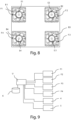
Figure 7 is a first rear view of the electrospindle ofFigure 6 to show a plurality of ventilation devices, included in said electrospindle, and a respective protection device for protecting each ventilation device; -
Figure 8 is a second rear view of the electrospindle ofFigure 7 , similar toFigure 7 , to show each ventilation device, in which the respective protection device has been removed; -
Figure 9 is a circuit diagram for showing a control unit included in the electrospindle ofFigure 6 , in which said control unit is connected to storage means, to a plurality of ventilation devices, to a first detecting device for detecting the temperature of the electric motor of the electrospindle, and to a second sensing device for detecting the temperature of a bearing included in said electrospindle. - In the various Figures, similar parts will be indicated with the same reference numbers.
- With reference to
Figure 1 , an improved electrospindle is described. - Said electrospindle includes:
- a
casing 11 comprising a first end wall 1A and asecond end wall 1B, opposite said first end wall 1A, - a
shaft 3 having a longitudinal axis A, arranged at least partially inside saidcasing 11, - an
electric motor 2 for rotating saidshaft 3 around said longitudinal axis A, arranged inside saidcasing 11, - a first
temperature detecting device 4, for sensing in at least one time instant ti with i=1...N, where N is a positive integer, a respective temperature value TMi associated with saidelectric motor 2, - a first ventilation device F for emitting an air jet, wherein the first said ventilation device F is arranged on said
second end wall 1B, in such a way that, when in use, said air jet is directed towards the inside a portion of saidcasing 1, arranged around saidelectric motor 2, wherein said first ventilation device F comprises at least one blade B, and a motor E for rotating said blade B, - storage means 6, wherein a first temperature threshold T S1 associated with said
electric motor 2, and at least one first velocity value associated with the motor E of the first ventilation device F are stored. - Said electrospindle also comprises:
- a control unit U, connected to said first
temperature detecting device 4, to said motor E of said first ventilation device F and to said storage means 6, and configured to:- ∘ acquire each temperature value TMi associated with said
electric motor 2 through said firsttemperature detecting device 4, - ∘ compare each temperature value TMi associated with said
electric motor 2 of said electrospindle with said first temperature threshold T S1 stored in said storage means 6, - ∘ if a temperature value TMi associated with said
electric motor 2 is greater than said first temperature threshold T S1, send a control signal to said motor E of said first ventilation device, so that the velocity value of motor E of said first ventilation device F is equal to said first velocity value stored in said storage means 6.
- ∘ acquire each temperature value TMi associated with said
- Said first velocity value associated with said motor of said motor E of said first ventilation device F and stored in said storage means 6 is a predetermined velocity value VREF.
- Said predetermined velocity value VREF it is a fixed value.
- Said fixed value can be a value chosen regardless of the temperature of the electric motor of the electrospindle, or a value depending on the temperature of the electrospindle electric motor.
- With reference to the electrospindle
electric motor 2, saidelectric motor 2 comprises astator 21 and arotor 22. - The
rotor 22 is arranged inside saidstator 21. - With reference to the
shaft 3, saidshaft 3 is arranged at least partially inside saidelectric motor 2. - In particular, the
shaft 3 is arranged inside therotor 22 of theelectric motor 2. - The
shaft 3 is integral with the electric motor 2 (in particular with therotor 22 of the electric motor 2) so that the rotation of saidelectric motor 2 causes the rotation of saidshaft 3. - The rotation of said
shaft 3 causes the rotation of thetool 7 mounted on the electrospindle. - With reference to the first detecting
device 4, said first detecting device can be arranged on a portion of thecasing 11 of the electrospindle at, or near saidelectric motor 2. - In the example being described, said first detecting
device 4 is a first temperature sensor. - With reference to the first ventilation device F, the air jet generated by said first ventilation device F is directed inside a portion of said
casing 1 arranged around theelectric motor 2 of the electrospindle. - It is preferable that the electrospindle comprises a duct for joining the first ventilation device F to the
electric motor 2 of the electrospindle, so that the air jet generated by said first ventilation device F easily reaches said electric motor. - In particular that said duct has an axis, which coincides with the longitudinal axis A of
shaft 3 of the electrospindle. - In the example described, the motor E for rotating the blade B is an electric motor, different from the electric motor of the electrospindle.
-
Figures 2 and 3 show thesecond end wall 1B of the electrospindle, wherein the first ventilation device F is positioned, respectively with a protection device S to protect said first ventilation device, and without said protection device S. - In the example described, said protective device S is a casing.
- With reference to the storage means 6, said storage means 6 comprise a memory.
- In the example described, said storage means are external to said control unit U.
- However, said storage means can be arranged inside said control unit, without departing from the scope of the invention.
- As mentioned, a first temperature threshold T S1 associated with said
electric motor 2, and a first velocity value associated with the motor E of the first ventilation device F are stored in said storage means. - When the electrospindle is in use, the control unit U acquires temperature values TMi associated with the
electric motor 2 of the electrospindle (via the first temperature detecting device 4) over time, compares each of said temperature values TMi with said first temperature threshold T S1, and sends a command signal to the motor E of the first ventilation device F, so that the velocity of said motor E is equal to said first velocity value when a temperature value TMi is greater than said first temperature threshold T S1. - In a variant, further data can be stored in said storage means 6.
- For example, the following data can be stored in said storage means: a reference ratio ΔTref between a predetermined temperature difference T ref2 - Tref1 and a predetermined time interval Δt.
- In this case, said control unit U can be configured to:
- ∘ calculate in a plurality of predetermined time intervals Δt a respective ratio

electric motor 2 of said electrospindle varies in each predetermined time interval Δt,
wherein- Tfin is the temperature of said
electric motor 2 of said electrospindle measured at the end of said predetermined time interval Δt (through said first temperature detecting device 4), - Tin is the temperature of said
electric motor 2 of said electrospindle measured at the beginning of said predetermined time interval Δt (through said first temperature detecting device 4),
- Tfin is the temperature of said
- ∘ compare each ratio ΔT calculated with said reference ratio ΔTref ;
- ∘ if a ratio calculated ΔT is greater than said reference ratio ΔTref, calculate a respective velocity value v M1i of the motor E of said first ventilation device F using the following formula:

n M1 is a number of revolutions of the motor E of said first ventilation device F per minute min, wherein
electric motor 2 of said electrospindle, wherein said first velocity value is equal to said calculated velocity value v M1 i, and - ∘ send a control signal to said motor E of said first ventilation device F, so that the velocity of said motor E of said first ventilation device F changes over time according to said formula.
- The predetermined time interval Δt used in the reference ratio ΔTref stored in said storage means 6 is equal to each predetermined time interval, wherein a respective ratio ΔT is to be calculated.
- In other words, whenever the velocity value v M1i is calculated according to the above formula, said value is stored in said storage means 6, so that said first velocity value is equal to said calculated velocity value v M1i .
- Differently from the case in which said first velocity value is a predetermined velocity value VREF, which is a fixed value, said first velocity value is a dynamic value, i.e. a value that changes over time.
- The ventilation device F can further comprise detection means for detecting in at least one time instant ti a respective velocity value VMi associated with the motor E of the first ventilation device F.
- Said control unit U can be configured to acquire each velocity value VMi, associated with the motor E of said first ventilation device F to check whether the blade B rotates.
- Furthermore, it is preferable that said control unit U be configured so as not to send any control signal to the motor E of the first ventilation device F if a temperature value TMi associated with the
electric motor 2 of the electrospindle is less than, or equal to said first temperature threshold T S1. - In the example described, said electrospindle preferably comprises:
- a
bearing 13, and - a second
temperature detecting device 5 for detecting in at least one time instant ti a respective temperature value TCi associated with saidbearing 13. - The first velocity value associated with the motor E of the ventilation device F and stored in said storage means 6 is a value, which depends on the temperature of said
bearing 13. - A second temperature threshold T S2 associated with said
bearing 13 is stored in said storage means 6. - Furthermore, said control unit U is connected to said second
temperature sensing device 5 and configured to: - ∘ acquire each temperature value TCi associated with said
bearing 13 through said secondtemperature detecting device 5, - ∘ compare each temperature value TCi associated with said
bearing 13 with said second temperature threshold T S2 stored in said storage means 6, - ∘ if a temperature value TCi associated with said
bearing 13 is greater than said second temperature threshold T S2, calculate a respective velocity value vCi of the motor E of said first ventilation device F using the following formula: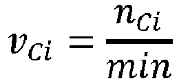
-

- b is a predetermined dimensionless value depending on the thermal characteristics of said
bearing 13, wherein said first velocity value is equal to said calculated velocity value vCi, and
-
- ∘ send a control signal to said motor E of said first ventilation device F, so that the velocity of said motor E of said first ventilation device F is equal to said calculated velocity value vCi.
- In other words, whenever the velocity value vCi is calculated according to the above formula, said value is stored in said storage means 6, so that said first velocity value is equal to calculated said velocity value vCi.
- Therefore, even if the electrospindle comprises a
bearing 13, said first velocity value is a dynamic value, i.e. a value that changes over time. - In an alternative, in addition to the first velocity value associated with the motor E of the ventilation device F (in which said first velocity value is a value depending on the temperature of said bearing 13) and a second temperature threshold T S2 associated with the
bearing 13, a second velocity value associated with the electric motor E of the ventilation device F and dependent on the temperature of saidelectric motor 2 of said electrospindle is stored in said storage means 6. - In said alternative, said control unit U can be connected to said second
temperature detecting device 5 and configured to: - ∘ acquire each temperature value TCi associated with said
bearing 13 through said secondtemperature detecting device 5, - ∘ compare each temperature value TCi associated with said
bearing 13 with said second temperature threshold T S2 stored in said storage means 6, - ∘ if a temperature value TCi associated with said
bearing 13 is greater than said second temperature threshold T S2, calculate a respective velocity value vCi of the motor E of said first ventilation device F using the following first formula:
-

- b is a predetermined dimensionless value depending on the thermal characteristics of said
bearing 13, wherein said first velocity value is equal to said calculated velocity value vCi,
-
- ∘ calculate a respective velocity value vMi of the motor E of said first ventilation device F using the following second formula:

n M2 is a further number of revolutions per minute of the motor E of said first ventilation device F at the minute min, in which
electric motor 2 of said electrospindle, wherein said second velocity value is equal to said calculated velocity value v M2i , - ∘ compare in at least one time instant ti each velocity value vCi of the motor E of said first ventilation device F with a respective velocity value v M2i of the motor E of said first ventilation device F to identify a maximum velocity value vmax between said velocity value vCi of the motor E of said first ventilation device F calculated by means of the first formula and said velocity value v M2i of the
electric motor 2 of said electrospindle calculated using the second formula, and - ∘ send a control signal to said motor E of said first ventilation device F, so that the velocity of said motor E of said first ventilation device F is equal to said maximum velocity value vmax .
- In other words, in said alternative, the control unit U identifies the maximum velocity value vmax between the velocity value vCi calculated using the first formula, and the velocity value v M2i calculated using the second formula, and sends a control signal to the motor E of the first ventilation device F, so that the velocity of said motor E of said first ventilation device F is equal to said maximum velocity value vmax .
- With reference to the
bearing 13, saidbearing 13 is arranged on said first end wall 1A of saidcasing 11. - With reference to the second detecting
device 5, said second sensing device is a second temperature sensor. - Furthermore, said control unit U can be configured not to send any control signal to said motor E of said first ventilation device F when said temperature value TCi associated with said
bearing 13 is less than or equal to said second temperature threshold T S2. - A third temperature threshold T S3 can be stored in said storage means 6 and said control unit U can be configured to:
- ∘ compare each temperature value TMi associated with said
electric motor 2 of said electrospindle with said third temperature threshold T S3, - ∘ if said temperature value TMi is greater than said third temperature threshold T S3, send an alarm signal and/or a control signal to the motor E of said first ventilation device F, so that the blade B rotates at a velocity that is the maximum velocity associated with said motor E of said first ventilation device F.
- Said third temperature threshold T S3 is associated with said
electric motor 2. - In other words, said third temperature threshold T S3 is a further temperature threshold associated with the
electric motor 2 with respect to the first temperature threshold T S1 mentioned above. - In particular, said third temperature threshold T S3 associated with the
electric motor 2 is different from said first temperature threshold T S1 associated with theelectric motor 2. - More specifically, it is preferable that said third temperature threshold T S3 is greater than said first temperature threshold T S1.
- Furthermore, a fourth temperature threshold T S4 can be stored in said storage means 6 and said control unit U can be configured to:
- ∘ compare each temperature value TCi associated with said
bearing 13 with said fourth temperature threshold T S4, - ∘ if said temperature value TCi is greater than said fourth temperature threshold T S4, send an alarm signal and/or a control signal to the motor E of said first ventilation device F, so that the blade B rotates at a velocity that is the maximum velocity associated with said motor E of said first ventilation device F.
- Said fourth temperature threshold T S4 is associated with said
bearing 13. - In other words, said fourth temperature threshold T S4 is a further temperature threshold associated with the bearing 13 with respect to the second temperature threshold T S2 mentioned above.
- In particular, said fourth temperature threshold T S4 associated with the
bearing 13 is different from said second temperature threshold T S2 associated with bearing 13. - More particularly, it is preferable that said fourth temperature threshold T S4 is greater than said second temperature threshold T S2.
-
Figures 6 to 9 show a second embodiment of the electrospindle. - In said second embodiment, said electrospindle comprises a plurality of ventilation devices for cooling the
electric motor 2 of the electrospindle itself. - In particular, said electrospindle comprises four ventilation devices: a first ventilation device F1, a second ventilation device F2, a third ventilation device F3, and a fourth ventilation device F4.
- Each ventilation device F1, F2, F3, F4 respectively comprises at least one blade B1, B2, B3, B4 and a motor E1, E2, E3, E4 for rotating said blade B1, B2, B3, B4.
- Each ventilation device F1, F2, F3, F4 is arranged on said
second end wall 1B of saidcasing 1. - The electrospindle comprises a respective protection device S1, S2, S3, S4 to protect each ventilation device F1,F2, F3, F4.
- In the example described, each protection device S1, S2, S3, S4 is a respective carter.
- Said control unit U is configured to:
- ∘ acquire each temperature value TMi associated with said
electric motor 2 of said electrospindle through said firsttemperature detecting device 4, - ∘ compare each temperature value TMi associated with said
electric motor 2 of said electrospindle with said first temperature threshold T S1 stored in said storage means 6, - ∘ if a temperature value TMi associated with said
electric motor 2 of said electrospindle is greater than said first temperature threshold T S1, - ∘ send a respective control signal to the respective motor E1, E2, E3, E4 of each ventilation device F1, F2, F3, F4, so that the velocity value of each motor E1, E2, E3, E4 of each ventilation device F1, F2, F3, F4 is equal to said first velocity value stored in said storage means 6.
- In other words, differently from the first embodiment, the control unit U is configured to send a number of command signals equal to the number of ventilation devices so that the velocity value of the respective motor of each ventilation device is equal to said first velocity value.
- In said second embodiment, the electrospindle comprises a plurality of ducts (not shown), in particular a respective duct for each ventilation device F1, F2, F3, F4, so that a respective air jet is emitted into a respective duct.
- The ducts of said plurality of ducts are arranged inside the casing in such a way that the engine is in a central position with respect to said ducts.
- When the ventilation devices F1, F2, F3, F4 are in use, the ducts allow cooling a portion of the
casing 1 arranged around theelectric motor 2 of the electrospindle. - Each duct of said plurality of ducts has a respective axis, parallel to the longitudinal axis A of the shaft and each ventilation device F1, F2, F3, F4 is arranged along the axis of a respective duct.
- In particular, each duct has a first end and a second end.
- Each ventilation device can be arranged at said first end of a respective duct, while the second end of each duct is a free end.
- Differently from the first embodiment of the electrospindle described above (in which the electrospindle comprises a single ventilation device), in the second embodiment, i.e., when the electrospindle comprises a plurality of ventilation devices, the control unit U is configured to send a respective command signal to each motor E1, E2, E3, E4 of the respective ventilation device F1, F2, F3, F4.
- Consequently, the control unit U is configured to send a plurality of command signals according to the number of ventilation devices F1, F2, F3, F4 included in the electrospindle.
- Furthermore, the present invention relates to a machining head comprising at least one electrospindle as described above with reference to the first embodiment or the second embodiment.
- The present invention also refers to a machine tool for machining parts, comprising:
- a base,
- a working table for supporting at least one workpiece, wherein said working table is arranged on said base, and
- a working unit for working said piece, wherein said working unit comprises said at least one working head mentioned above.
- A first advantage of the improved electrospindle object of the invention is given by the possibility of adjusting the velocity of the motor of at least one ventilation device in order to cool the electric motor of the electrospindle according to the temperature associated with said electric motor, in which said temperature is detected by at least one temperature sensor installed on said electrospindle.
- A further advantage is given by the possibility of emitting an air jet inside the electrospindle casing, to cool a portion of said casing located inside the electric motor on the basis of the amount of heat to be dissipated, with a level of reduced noise.
- The present invention has been described for illustrative but not limitative purposes, according to its preferred embodiments, but it is to be understood that modifications and/or changes can be introduced by those skilled in the art without departing from the relevant scope as defined in the enclosed claims.
Claims (13)
- Electrospindle comprising:- a casing (11) comprising a first end wall (1A) and a second end wall (1B), opposite to said first end wall (1A),- a shaft (3) having a longitudinal axis (A), arranged at least partially inside said casing (11),- an electric motor (2) for rotating said shaft (3) around said longitudinal axis (A), wherein said electric motor is arranged inside said casing (11),- a first temperature detecting device (4) for detecting in at least one time instant ti with i=1...N, where N is a positive integer, a respective temperature value TMi associated with said electric motor (2),- at least one first ventilation device (F) for emitting an air jet, wherein said first ventilation device (F) is arranged on said end wall (1B) in such a way that, when in use, said air jet is directed inside a portion of said casing (11) arranged around said electric motor (2), said first ventilation device (F) comprising at least one blade (B) and a motor (E) for rotating said blade (B),- storage means (6) wherein a first temperature threshold T S1 associated with said electric motor (2) and at least one first velocity value associated with the motor (E) of said first ventilation device (F) are stored,- a control unit (U), connected to said first temperature detecting device (4), to said motor (E) of said first ventilation device (F) and to said storage means (6), and configured to:∘ acquire each temperature value TMi associated with said electric motor (2) of said electrospindle through said first temperature detecting device (4),∘ compare each temperature value TMi associated with said electric motor (2) of said electrospindle with said first temperature threshold T S1 stored in said storage means (6),∘ if a temperature value TMi associated with said electric motor (2) of said electrospindle is greater than said first temperature threshold T S1, send a control signal to said motor (E) of said first ventilation device (F) so that the value of velocity of said motor (E) of said first ventilation device (F) is equal to said first velocity value stored in said storage means (6).
- Electrospindle according to claim 1, wherein said first velocity value associated with said motor (E) of said first ventilation device (F) is a predetermined velocity value VREF.
- Electrospindle according to claim 1 or 2, wherein said first velocity value associated with said motor (E) of said first ventilation device (F) is a value depending on the temperature of the electric motor (2) of said electrospindle.
- Electrospindle according to the previous claim, whereinthe following data are stored in said storage means (6):
a reference ratio ΔTref between a predetermined temperature difference T ref2 - T ref1 and a predetermined time interval Δt,whereinsaid control unit (U) is configured to:∘ calculate in a plurality of predetermined time intervals Δt a respective ratio
whereTfin is the temperature of said electric motor (2) of said electrospindle detected at the end of said predetermined time interval Δt,Tin is the temperature of said electric motor (2) of said electrospindle detected at the beginning of said predetermined time interval Δt,∘ compare each calculated ratio ΔT with said reference ratio ΔTref ;∘ if a calculated ratio ΔT is greater than said reference ratio ΔTref, calculate a respective velocity value v M1i of the motor (E) of said first ventilation device (F) using the following formula:
n M1 is a number of revolutions of the motor (E) of said first ventilation device (F) per minute min, wherein ∘ send a control signal to said motor (E) of said first ventilation device (F) so that the velocity of said motor (E) of said first ventilation device (F) changes over time according to said formula.
 - Electrospindle according to any one of the previous claims, whereinsaid first ventilation device (F) comprises detecting means for detecting in said time instant ti a respective velocity value VMi associated with said motor (E) of said first ventilation device (F), andwhereinsaid control unit (U) is configured to:∘ acquire each velocity value VMi associated with the motor (E) of said first ventilation device (F) to verify if the blade (B) rotates.
- Electrospindle according to any one of the previous claims, wherein said control unit (U) is configured not to send any control signal to said motor (E) of said first ventilation device (F) if a temperature value TMi associated with said electric motor (2) of said electrospindle is less than or equal to said first temperature threshold T S1.
- Electrospindle according to claim 1 or 2, whereinsaid electrospindle comprises:- a bearing (13),- a second temperature detecting device (5) for detecting in at least one time instant ti a respective temperature value TCi associated with said bearing (13),whereinsaid first velocity value associated with said motor (E) of said first ventilation device (F) is a value depending on the temperature of said bearing (13),whereina second temperature threshold T S2 associated with said bearing (13) is stored in said storage means (6),whereinsaid control unit (U) is connected to said second temperature detecting device (5) is configured to:∘ acquire each temperature value TCi associated with said bearing (13) through said second temperature detecting device (5),∘ compare each temperature value TCi associated with said bearing (13) with said second temperature threshold T S2 stored in said storage means (6),∘ if a temperature value TCi associated with said bearing (13) is greater than said second temperature threshold T S2, calculate a respective velocity value vCi of the motor (E) of said first ventilation device (F) through the following formula:

nci is the number of revolutions of the motor (E) of said first ventilation device (F) per minute min, with ∘ send a control signal to said motor (E) of said first ventilation device (F) so that the velocity of said motor (E) of said first ventilation device (F) is equal to said calculated velocity value vCi.
 - Electrospindle according to claim 1 or 2, whereinsaid electrospindle comprises:- a bearing (13),- a second temperature detecting device (5) for detecting in at least one time instant ti a respective temperature value TCi associated with said bearing (13),whereinsaid first velocity value associated with said motor (E) of said first ventilation device (F) is a value depending on the temperature of said bearing (13),whereina second velocity value associated with said electric motor (E) of said first ventilation device (F) and depending on the temperature of said electric motor (2) of said electrospindle, as well as a second temperature threshold T S2 associated with said bearing (13) are stored in said storage means (6),whereinsaid control unit (U) is connected to said second temperature detecting device (5) and configured to:∘ acquire each temperature value TCi associated with said bearing (13) through said second temperature detecting device (5),∘ compare each temperature value TCi associated with said bearing (13) with said second temperature threshold T S2 stored in said storage means (6),∘ if a temperature value TCi associated with said bearing (13) is greater of said second temperature threshold T S2, calculate a respective velocity value vCi of the motor (E) of said first ventilation device (F) through the following first formula:

nci is the number of revolutions of the motor (E) of said first ventilation device (F) per minute min, with ∘ calculate a respective velocity value v M2i of the motor (E) of said first ventilation device (F) through the following second formula:
n M2 is a further number of revolutions of the motor (E) of said first ventilation device (F) per minute min, wherein ∘ compare in at least one time instant ti each velocity value vCi of the motor (E) of said first ventilation device (F) calculated through the first formula with a respective velocity value v M2i of the motor (E) of said first ventilation device (F) calculated through the second formula to identify a maximum velocity value vmax between said velocity value vCi of the motor (E) of said first ventilation device (F) calculated through the first formula and said velocity value v M2i of the motor (E) of said first ventilation device (F) calculated through the second formula, and∘ send a control signal to said motor (E) of said first ventilation device (F) so that the velocity of said motor (E) of said first ventilation device (F) is equal to said maximum velocity value vmax .
 - Electrospindle according to claim 7 or 8, wherein said control unit (U) is configured not to send any control signal to said motor (E) of said first ventilation device (F) when said temperature value TCi associated with said bearing (13) is less than or equal to said second temperature threshold T S2.
- Electrospindle according to any one of the previous claims, whereina third temperature threshold T S3 is stored in said storage means (6),whereinsaid control unit (U) is configured to:∘ compare each temperature value TMi associated with said electric motor (2) of said electrospindle with said third temperature threshold T S3,∘ if said temperature value TMi is greater than said third temperature threshold T S3, sand an alarm signal and/or a control signal to said motor (E) of said first ventilation device (F) so that the blade (B) rotates at a velocity, which is the maximum velocity associated with said motor (E) of said first ventilation device (F).
- Electrospindle according to any one of the previous claims 7-10, whereina fourth temperature threshold T S4 is stored in said storage means (6),whereinsaid control unit (U) is configured to:∘ compare each temperature value TCi associated with said bearing (13) with said fourth temperature threshold T S4,∘ if said temperature value TCi is greater than said fourth temperature threshold T S4, send an alarm signal and/or a control signal to the motor (E) of said first ventilation device (F) so that the blade (B) rotates at a velocity, which is the maximum velocity associated with said motor (E) of said first ventilation device (F).
- Working head comprising at least one electrospindle according to any one of the claims 1-11.
- Machine tool for working pieces, comprising:- a basement,- a working table for supporting at least one piece, wherein said working table is arranged on said basement, and- a working unit for working said piece, wherein said working unit comprising at least one working head according to the previous claim.
Applications Claiming Priority (1)
| Application Number | Priority Date | Filing Date | Title |
|---|---|---|---|
| IT102022000004217A IT202200004217A1 (en) | 2022-03-07 | 2022-03-07 | Improved electrospindle. |
Publications (1)
| Publication Number | Publication Date |
|---|---|
| EP4242759A1 true EP4242759A1 (en) | 2023-09-13 |
Family
ID=81850923
Family Applications (1)
| Application Number | Title | Priority Date | Filing Date |
|---|---|---|---|
| EP23159951.5A Pending EP4242759A1 (en) | 2022-03-07 | 2023-03-03 | Improved electrospindle |
Country Status (2)
| Country | Link |
|---|---|
| EP (1) | EP4242759A1 (en) |
| IT (1) | IT202200004217A1 (en) |
Citations (7)
| Publication number | Priority date | Publication date | Assignee | Title |
|---|---|---|---|---|
| JPH07237085A (en) * | 1994-03-01 | 1995-09-12 | Rokuroku Sangyo Kk | Main spindle cooling device for finishing machine |
| US5594603A (en) * | 1993-12-02 | 1997-01-14 | Fujitsu Limited | Seek control system based upon a detected temperature of a positioning mechanism in a disk device |
| US6078115A (en) * | 1996-11-07 | 2000-06-20 | Fanuc Ltd | Air-cooled motor |
| US20050207899A1 (en) * | 2003-08-08 | 2005-09-22 | Shin Caterpillar Mitsubishi Ltd | Method for controlling number of revolution of fan |
| US20160351041A1 (en) * | 2015-06-01 | 2016-12-01 | Fanuc Corporation | Motor drive device and method capable of notifying malfunction in fluid flow in heat sink |
| US20190329370A1 (en) * | 2018-04-27 | 2019-10-31 | Fanuc Corporation | Motor controller and machine tool |
| CN113305311A (en) * | 2021-07-01 | 2021-08-27 | 卧龙电气驱动集团股份有限公司 | Electric spindle and air-cooled temperature control system |
-
2022
- 2022-03-07 IT IT102022000004217A patent/IT202200004217A1/en unknown
-
2023
- 2023-03-03 EP EP23159951.5A patent/EP4242759A1/en active Pending
Patent Citations (7)
| Publication number | Priority date | Publication date | Assignee | Title |
|---|---|---|---|---|
| US5594603A (en) * | 1993-12-02 | 1997-01-14 | Fujitsu Limited | Seek control system based upon a detected temperature of a positioning mechanism in a disk device |
| JPH07237085A (en) * | 1994-03-01 | 1995-09-12 | Rokuroku Sangyo Kk | Main spindle cooling device for finishing machine |
| US6078115A (en) * | 1996-11-07 | 2000-06-20 | Fanuc Ltd | Air-cooled motor |
| US20050207899A1 (en) * | 2003-08-08 | 2005-09-22 | Shin Caterpillar Mitsubishi Ltd | Method for controlling number of revolution of fan |
| US20160351041A1 (en) * | 2015-06-01 | 2016-12-01 | Fanuc Corporation | Motor drive device and method capable of notifying malfunction in fluid flow in heat sink |
| US20190329370A1 (en) * | 2018-04-27 | 2019-10-31 | Fanuc Corporation | Motor controller and machine tool |
| CN113305311A (en) * | 2021-07-01 | 2021-08-27 | 卧龙电气驱动集团股份有限公司 | Electric spindle and air-cooled temperature control system |
Also Published As
| Publication number | Publication date |
|---|---|
| IT202200004217A1 (en) | 2023-09-07 |
Similar Documents
| Publication | Publication Date | Title |
|---|---|---|
| US6655929B2 (en) | Cooling fan dust guard | |
| US6700266B2 (en) | Multiple fault redundant motor | |
| JP6312645B2 (en) | Motor driving apparatus capable of reporting abnormal operation of fan and method thereof | |
| EP0470265A1 (en) | Balance structure of motor | |
| US9558303B2 (en) | Tool gravity center position estimation device and machine tool | |
| US20190363608A1 (en) | Connecting element for connecting a motor shaft of a motor to a rotary encoder and motor | |
| CN106211706B (en) | The method of the flow abnormalities of motor drive and notice fluid | |
| EP3943221A1 (en) | Lubricating oil supply unit and bearing device | |
| HU204212B (en) | Method and control arrangement for protecting against the excess of permissible revolution number of centrifuges having high speed of revolutions | |
| US20160184952A1 (en) | Recovery rotational speed for diamond-tipped core drilling devices after a temperature switch-off (overheating of the motor) | |
| US6712515B2 (en) | Redundant ball bearing | |
| US20030122438A1 (en) | Method and apparatus for fan redundancy | |
| JPH11252857A (en) | Electric motor and heat sink device using the same | |
| WO2022059573A1 (en) | Bearing device | |
| US20040045375A1 (en) | Method and apparatus for detecting bearing failure | |
| KR102819906B1 (en) | bearing device | |
| KR20170069034A (en) | Fan monitoring system | |
| CN111954762A (en) | Method for controlling at least one radial fan in a refrigeration plant and radial fan | |
| CA3005534C (en) | Static pressure tap | |
| EP1184762B1 (en) | Rotary hammer | |
| GB410015A (en) | Improvements in or relating to high speed electrically driven portable dulling and like tools | |
| JP2013003121A (en) | Rotary encoder, and motor with rotary encoder | |
| JP2001269828A (en) | Magnetic bearing devices for machine tools | |
| US20210265897A1 (en) | Electric motor and ventilator with corresponding electric motor | |
| KR102746045B1 (en) | Device for protecting driving motor and Apparatus for driving rotor disk having the same |
Legal Events
| Date | Code | Title | Description |
|---|---|---|---|
| PUAI | Public reference made under article 153(3) epc to a published international application that has entered the european phase |
Free format text: ORIGINAL CODE: 0009012 |
|
| STAA | Information on the status of an ep patent application or granted ep patent |
Free format text: STATUS: THE APPLICATION HAS BEEN PUBLISHED |
|
| AK | Designated contracting states |
Kind code of ref document: A1 Designated state(s): AL AT BE BG CH CY CZ DE DK EE ES FI FR GB GR HR HU IE IS IT LI LT LU LV MC ME MK MT NL NO PL PT RO RS SE SI SK SM TR |
|
| STAA | Information on the status of an ep patent application or granted ep patent |
Free format text: STATUS: REQUEST FOR EXAMINATION WAS MADE |
|
| 17P | Request for examination filed |
Effective date: 20240311 |
|
| RBV | Designated contracting states (corrected) |
Designated state(s): AL AT BE BG CH CY CZ DE DK EE ES FI FR GB GR HR HU IE IS IT LI LT LU LV MC ME MK MT NL NO PL PT RO RS SE SI SK SM TR |
|
| STAA | Information on the status of an ep patent application or granted ep patent |
Free format text: STATUS: EXAMINATION IS IN PROGRESS |
|
| 17Q | First examination report despatched |
Effective date: 20260203 |