EP4242672A1 - Isolation resistance monitoring for high voltage systems - Google Patents
Isolation resistance monitoring for high voltage systems Download PDFInfo
- Publication number
- EP4242672A1 EP4242672A1 EP23160557.7A EP23160557A EP4242672A1 EP 4242672 A1 EP4242672 A1 EP 4242672A1 EP 23160557 A EP23160557 A EP 23160557A EP 4242672 A1 EP4242672 A1 EP 4242672A1
- Authority
- EP
- European Patent Office
- Prior art keywords
- isolation
- smartcell
- charging
- high voltage
- electric vehicle
- Prior art date
- Legal status (The legal status is an assumption and is not a legal conclusion. Google has not performed a legal analysis and makes no representation as to the accuracy of the status listed.)
- Granted
Links
Images



Classifications
-
- G—PHYSICS
- G01—MEASURING; TESTING
- G01R—MEASURING ELECTRIC VARIABLES; MEASURING MAGNETIC VARIABLES
- G01R31/00—Arrangements for testing electric properties; Arrangements for locating electric faults; Arrangements for electrical testing characterised by what is being tested not provided for elsewhere
- G01R31/005—Testing of electric installations on transport means
- G01R31/006—Testing of electric installations on transport means on road vehicles, e.g. automobiles or trucks
-
- G—PHYSICS
- G01—MEASURING; TESTING
- G01R—MEASURING ELECTRIC VARIABLES; MEASURING MAGNETIC VARIABLES
- G01R27/00—Arrangements for measuring resistance, reactance, impedance, or electric characteristics derived therefrom
- G01R27/02—Measuring real or complex resistance, reactance, impedance, or other two-pole characteristics derived therefrom, e.g. time constant
- G01R27/025—Measuring very high resistances, e.g. isolation resistances, i.e. megohm-meters
-
- B—PERFORMING OPERATIONS; TRANSPORTING
- B60—VEHICLES IN GENERAL
- B60L—PROPULSION OF ELECTRICALLY-PROPELLED VEHICLES; SUPPLYING ELECTRIC POWER FOR AUXILIARY EQUIPMENT OF ELECTRICALLY-PROPELLED VEHICLES; ELECTRODYNAMIC BRAKE SYSTEMS FOR VEHICLES IN GENERAL; MAGNETIC SUSPENSION OR LEVITATION FOR VEHICLES; MONITORING OPERATING VARIABLES OF ELECTRICALLY-PROPELLED VEHICLES; ELECTRIC SAFETY DEVICES FOR ELECTRICALLY-PROPELLED VEHICLES
- B60L53/00—Methods of charging batteries, specially adapted for electric vehicles; Charging stations or on-board charging equipment therefor; Exchange of energy storage elements in electric vehicles
- B60L53/60—Monitoring or controlling charging stations
-
- G—PHYSICS
- G01—MEASURING; TESTING
- G01R—MEASURING ELECTRIC VARIABLES; MEASURING MAGNETIC VARIABLES
- G01R27/00—Arrangements for measuring resistance, reactance, impedance, or electric characteristics derived therefrom
- G01R27/02—Measuring real or complex resistance, reactance, impedance, or other two-pole characteristics derived therefrom, e.g. time constant
-
- G—PHYSICS
- G01—MEASURING; TESTING
- G01R—MEASURING ELECTRIC VARIABLES; MEASURING MAGNETIC VARIABLES
- G01R31/00—Arrangements for testing electric properties; Arrangements for locating electric faults; Arrangements for electrical testing characterised by what is being tested not provided for elsewhere
- G01R31/50—Testing of electric apparatus, lines, cables or components for short-circuits, continuity, leakage current or incorrect line connections
- G01R31/52—Testing for short-circuits, leakage current or ground faults
-
- Y—GENERAL TAGGING OF NEW TECHNOLOGICAL DEVELOPMENTS; GENERAL TAGGING OF CROSS-SECTIONAL TECHNOLOGIES SPANNING OVER SEVERAL SECTIONS OF THE IPC; TECHNICAL SUBJECTS COVERED BY FORMER USPC CROSS-REFERENCE ART COLLECTIONS [XRACs] AND DIGESTS
- Y02—TECHNOLOGIES OR APPLICATIONS FOR MITIGATION OR ADAPTATION AGAINST CLIMATE CHANGE
- Y02T—CLIMATE CHANGE MITIGATION TECHNOLOGIES RELATED TO TRANSPORTATION
- Y02T10/00—Road transport of goods or passengers
- Y02T10/60—Other road transportation technologies with climate change mitigation effect
- Y02T10/70—Energy storage systems for electromobility, e.g. batteries
-
- Y—GENERAL TAGGING OF NEW TECHNOLOGICAL DEVELOPMENTS; GENERAL TAGGING OF CROSS-SECTIONAL TECHNOLOGIES SPANNING OVER SEVERAL SECTIONS OF THE IPC; TECHNICAL SUBJECTS COVERED BY FORMER USPC CROSS-REFERENCE ART COLLECTIONS [XRACs] AND DIGESTS
- Y02—TECHNOLOGIES OR APPLICATIONS FOR MITIGATION OR ADAPTATION AGAINST CLIMATE CHANGE
- Y02T—CLIMATE CHANGE MITIGATION TECHNOLOGIES RELATED TO TRANSPORTATION
- Y02T10/00—Road transport of goods or passengers
- Y02T10/60—Other road transportation technologies with climate change mitigation effect
- Y02T10/7072—Electromobility specific charging systems or methods for batteries, ultracapacitors, supercapacitors or double-layer capacitors
-
- Y—GENERAL TAGGING OF NEW TECHNOLOGICAL DEVELOPMENTS; GENERAL TAGGING OF CROSS-SECTIONAL TECHNOLOGIES SPANNING OVER SEVERAL SECTIONS OF THE IPC; TECHNICAL SUBJECTS COVERED BY FORMER USPC CROSS-REFERENCE ART COLLECTIONS [XRACs] AND DIGESTS
- Y02—TECHNOLOGIES OR APPLICATIONS FOR MITIGATION OR ADAPTATION AGAINST CLIMATE CHANGE
- Y02T—CLIMATE CHANGE MITIGATION TECHNOLOGIES RELATED TO TRANSPORTATION
- Y02T90/00—Enabling technologies or technologies with a potential or indirect contribution to GHG emissions mitigation
- Y02T90/10—Technologies relating to charging of electric vehicles
- Y02T90/12—Electric charging stations
Definitions
- One or more embodiments herein relate to electrical circuits, and more specifically, to systems, methods, and/or computer program products that can facilitate isolation resistance monitoring for high voltage systems.
- An embodiment includes an isolation resistance monitoring system comprising an electrical circuit.
- the electrical circuit further comprises one or more resistors and a voltage meter which measures voltage, such that the voltage measurement assists with monitoring isolation resistance, simultaneously, for a smartcell system of an electric vehicle, and for a direct current (DC) charging source external to the electric vehicle.
- DC direct current
- the isolation resistance monitoring method comprises monitoring, by an isolation resistance monitoring system, isolation resistance, simultaneously, for a smartcell system of an electric vehicle, and for a DC charging source external to the electric vehicle.
- the isolation fault detection method comprises detecting, by an isolation resistance monitoring system, an isolation fault in a smartcell system, wherein one or more contactors of the smartcell system are configured to design an isolation test for detecting the isolation fault.
- the principal challenge addressed by the invention is that it can provide a system for simultaneously monitoring isolation resistance of two isolated high voltage systems, galvanically connected to one another, wherein one high voltage system can be the smartcell system of an electric vehicle and the other high voltage system can be an external DC charging source for the electric vehicle.
- the isolation resistance monitoring system can also detect isolation fault in different areas of the smartcell system, which can further assist with providing good drivability for the electric vehicle, even when an isolation fault can be present.
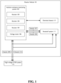
- FIG. 1 illustrates a block diagram of an isolation resistance monitoring system integrated with two high voltage systems, in accordance with one or more embodiments described herein.
- the block diagram comprises electric vehicle 101, isolation resistance monitoring system 102, resistors 103 -105, voltage meter 106, switches 107-110, smartcell system 111, high voltage EVSE system 112 and electrical chassis 113.
- electric vehicle 101 can comprise an isolation resistance monitoring system 102.
- Isolation resistance monitoring system 102 can be an electrical circuit comprising resistors 103, 104, and 105, and voltage meter 106.
- the isolation resistance monitoring system can monitor isolation resistance between the smartcell system 111 and the electrical chassis 113 of electric vehicle 101, and it can simultaneously monitor isolation resistance between the high voltage Electric Vehicle Supply Equipment (EVSE) system and the electrical chassis 113, wherein the EVSE system is an external DC charging station for electric vehicle 101.
- Isolation resistance monitoring system 102 can be electrically integrated with the smartcell system 111 via switches 107 and 108, wherein switches 107 and 108 can be respectively connected to each of the high voltage terminals of a high voltage bus of the smartcell system 111.
- isolation resistance monitoring system 102 can be electrically integrated with the high voltage EVSE system 112 via switches 109 and 110.
- Switches 109 and 110 can further provide a connection between the isolation resistance monitoring system 102 and the electrical circuit of the smartcell system 111, and they can allow the isolation resistance monitoring system to simultaneously monitor isolation resistance for the smartcell system and the high voltage EVSE system, during DC charging of electric vehicle 101.
- Isolation resistance monitoring system 102 can be integrated with the electrical chassis 113 of the electric vehicle 101, wherein the electrical chassis can be a reference point for the isolation resistance monitoring system 102.
- Voltage meter 106 can measure voltage through the smartcell system 111 and through the high voltage EVSE system 112 to assist the isolation resistance monitoring system 102 to monitor isolation resistance. Switches 107, 108, 109 and 110 can further assist the isolation resistance monitoring system 102 with measuring isolation resistance for electric vehicle 101. Isolation resistance monitoring system 102 can be controlled by a software and it can be used to locate isolation fault in different areas of the smartcell system 111, including isolation faults in cable harnesses, busbars, fuses, and other high voltage components of the smartcell system 111.
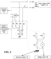
- FIG. 2 illustrates the architecture of the isolation resistance monitoring system, in accordance with one or more embodiments described herein.
- FIG. 2 comprises isolation resistance monitoring system 102, resistors 103-105, voltage meter 106, smartcell system 111, high voltage EVSE system 112, electrical chassis 113, and switches 107-110 of FIG. 1 , wherein resistors 103, 104 and 105 are respectively represented as R1, R2 and R3, and switches 107, 108, 109 and 110 are respectively represented as S1, S2, S3 and S4.
- resistor R3 can be connected in parallel with voltage meter 106.
- Resistors R1 and R2 can be connected in parallel with one another, and the parallel combination of resistor R3 and voltage meter 106 can be in series connection with the parallel combination of resistors R1 and R2.
- Switch S1 can be in series with resistor R1 and switch S2 can be in series with resistor R2 such that the isolation resistance monitoring system 102 can be galvanically connected with a high voltage bus of the smartcell system 111 via switches S1 and S2.
- the high voltage bus can be in parallel combination with one or more high voltage buses of smartcell system 111.
- switch S3 can be in series with resistor R1 and switch S4 can be in series with resistor R2 such that the isolation resistance monitoring system 102 can be galvanically connected with the smartcell system 111, and with high voltage EVSE system 112, wherein the high voltage EVSE system can be an external DC charging station, as discussed in one or more embodiments herein.
- switches S1, S2, S3 and S4 can be operated consecutively. Initially, all switches can be in the open position, switch S1 can be closed and the voltage through the circuit can be measured using the voltage meter 106, switch S1 can be opened, and the procedure can be repeated for switch S2 to measure isolation resistance for the parallel combination of high voltage buses of smartcell system. The procedure of consecutively opening and closing the plurality of switches can be repeated for switches S3 and S4 to measure isolation resistance for the smartcell system and for the high voltage EVSE system, wherein the smartcell system and the high voltage EVSE system are galvanically connected during DC charging.
- FIG. 3 illustrates the architecture of the isolation resistance monitoring system integrated with a smartcell system, in accordance with one or more embodiments described herein.
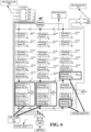
- FIG. 4 illustrates the architecture of the smartcell system, in accordance with one or more embodiments described herein.
- FIG. 3 and FIG. 4 comprise the smartcell system 111 and isolation resistance monitoring system 102 of FIG. 1 , contactors 301 - 314 of FIG. 3 , and smartcell battery pack 402, smartcell board 404, asynchronous motor (ASM) 406, high voltage bus 408, alternating current (AC) charging inlet 410, and DC charging inlet 411 of FIG. 4 .
- ASM synchronous motor
- AC alternating current
- the isolation resistance monitoring system 102 can be electrically integrated with the smartcell system 111 via switches S1 and S2 (also known as switches 107 and 108 per FIG. 1 and 2 ), as well as via switches S3 and S4 (also known as switches 109 and 110 per FIG. 3 and 4 ).
- the smartcell system topology comprises a smartcell battery pack 402 which can further comprise multiples of smartcell board 404.
- Each smartcell board 404 can control a battery module comprising one or more cells.
- a master node can control each smartcell board 404 and their respective battery modules such that the smartcell battery pack can produce different levels of AC output voltage at the pack level and it can produce different levels of DC output voltage at the pack or module level.
- a battery module can output up to 14 volts (V), and the one or more battery modules can be combined in series such that each series combination can be arranged to form three parallel strings of the battery modules.
- Each string can also comprise a combination of battery modules configured to form a high voltage bus 408 that can produce a galvanically isolated output of 400V.
- the 14 V battery modules on each string form the low voltage side of the smartcell system, which can be galvanically isolated from the high voltage buses on each string.
- the isolation resistance monitoring system 102 can be utilized for both AC and DC applications, for charging and non-charging use cases.
- the charging use cases can comprise DC charging of an electric vehicle via a high voltage EVSE system, during which the isolation resistance monitoring system can simultaneously monitor isolation resistance for the secondary circuit of the high voltage EVSE system and for the high voltage circuit of the smartcell system, including the high voltage buses and not including the low voltage, 14 V battery modules, by using switches S3 and S4.
- the isolated 400V bus if alive, can also be monitored by using S1 and S2.
- Contactors 301, 302, 305, 306, 307, and 308 can be closed for DC charging.
- the charging use cases can further comprise AC charging of the electric vehicle, during which isolation resistance can be monitored for the high voltage circuit of the smartcell system, including the high voltage buses and not including the low voltage, 14 V battery modules, by using switches S1 and S2.
- Contactors 301, 302, 311, 312, 313, and 314 can be closed for AC charging.
- the high voltage buses of the smartcell system can be energized to high voltage levels. Therefore, the solution can allow continuous isolation monitoring functionality for isolated high voltage buses with various voltage levels.
- the non-charging use cases can comprise isolation resistance measurement, as part of an isolation test, to detect isolation fault prior to AC and/or DC charging, during short-term and long-term parking, before every start-up, during every power-down, and before and after every service action of the electric vehicle.
- the high voltage buses of the smartcell system can be energized to safe voltage levels by the smartcell battery pack 402, wherein safe voltage levels can include voltage levels under 30 V for AC applications and voltage levels under 60 V for DC applications.
- the isolation resistance monitoring system 102 can detect isolation fault in the smartcell system 111, wherein the fault can be in cable harnesses, busbars, fuses, and other high voltage components of the smartcell system 111. Energizing the high voltage buses to non-hazardous voltage levels, for isolation resistance measurement for detecting isolation fault, can further allow service technicians to troubleshoot isolation faults much easier.
- the fault detection sequence which is described in greater detail in subsequent figures, can involve closing and opening several combinations of contactors 301 through 314 illustrated in the smartcell topology.
- the smartcell system 111 further comprises AC charging inlet 410 and DC charging inlet 411, and it is integrated with an asynchronous motor 406 (ASM 406).
- ASM is also known as the electric front axle drive (EFAD) since it drives the front axle of the electric vehicle.
- the isolation resistance monitoring system can employ the isolation fault detection sequence such that depending on where an isolation fault is detected in the smartcell system, it can prevent AC charging, DC charging or front wheel drive of the vehicle, by opening the respective contactors to the AC charging inlet, DC charging inlet and the ASM, and it can prevent energization of the high voltage buses.
- FIG. 5 illustrates an isolation resistance monitoring method that facilitates isolation resistance monitoring, in accordance with one or more embodiments described herein. Repetitive description of like elements and/or processes employed in respective embodiments is omitted for sake of brevity.
- environment 500 can comprise, at 502, an isolation resistance monitoring method which can facilitate monitoring, by an isolation resistance monitoring system, isolation resistance, simultaneously, for a smartcell system of an electric vehicle, and for a DC charging source external to the electric vehicle, wherein a voltage meter measures voltage to assist with the isolation resistance monitoring.
- FIG. 6 illustrates a flow diagram of an isolation resistance monitoring method that facilitates isolation resistance monitoring and isolation fault detection, in accordance with one or more embodiments described herein.
- environment 600 can comprise, at 502, an isolation resistance monitoring method which can facilitate monitoring, by an isolation resistance monitoring system, isolation resistance, simultaneously, for a smartcell system of an electric vehicle, and for a DC charging source external to the electric vehicle, wherein a voltage meter measures voltage to assist with the isolation resistance monitoring.
- the isolation resistance monitoring method can facilitate detecting, by an isolation resistance monitoring system, an isolation fault in the smartcell system, wherein one or more contactors of the smartcell system are configured to design an isolation test for detecting the isolation fault.
- FIG. 7 illustrates a flow diagram of an isolation resistance monitoring method that facilitates isolation fault detection, in accordance with one or more embodiments described herein. Repetitive description of like elements and/or processes employed in respective embodiments is omitted for sake of brevity.
- FIG. 7 is to be understood in conjunction with FIG. 3 and 4 where the smartcell system architecture is addressed.
- one or more contactors of a smartcell system can be configured to design an isolation test for detecting isolation fault, using the isolation resistance monitoring system, due to one or more components in the smartcell system.
- the isolation test can comprise two isolation test sequences, respectively, for a first and a second use case.
- the first use case comprises isolation fault detection in the smartcell system prior to AC charging and/or DC charging.
- the second use case comprises isolation fault detection in the smartcell system during short-term and long-term parking, before every start-up, during every power-down, and before and after every service action of an electric vehicle.
- the first isolation test sequence is described by steps 701 -706 which address the first use case comprising isolation fault detection in the smartcell system prior to AC charging and/or DC charging.
- all contactors can be in the open position.
- contactors 301, 302, 305, 306, 309, and 310 (as illustrated in FIG. 3 ) can be closed, and the system can be energized by the smartcell battery pack 402 to low DC voltage levels at 702, followed by isolation resistance measurement of the smartcell system 111 at 703. If an isolation failure is detected in the system, charging can be prevented at 704.
- the test can be concluded by opening contactors 301, 302, 305, 306, 309, and 310, at 705, and the smartcell battery pack can be allowed to be charged either via an AC charging source or a DC charging source, at 706. Further isolation resistance monitoring of the smartcell system can operate upon a request.
- the second isolation test sequence is described by steps 707-717 which address the second use case comprising isolation fault detection in the smartcell system 111 during short-term and long-term parking, before every start-up, during every power-down, and before and after every service action of an electric vehicle.
- all contactors can be in the open position.
- contactors 301, 302, 305, 306, 307, 308, 309, 310, 311, 312, 313, and 314 (as illustrated in FIG. 3 ) can be closed, and the system can be energized by the smartcell battery pack 402 to low DC voltage levels at 708.
- the isolation resistance of the smartcell system 111 can be measured by the isolation resistance monitoring system 102. If no isolation faults can be detected, high voltage energization of the smartcell system 111 can be allowed at 711, and if an isolation fault can be detected, contactors 311, 312, 313 and 314 can be disconnected at 710.
- step 710 If no isolation fault can be detected after step 710, it can imply that the fault exists within the onboard section of the AC charging bus, since contactors 311, 312, 313, and 314 can provide a connection between the smartcell system 111 and the AC charging inlet 410. Thus, AC charging can be prevented, and high voltage energization of the smartcell system can be allowed at 713. If an isolation fault can be detected after step 710, contactors 307 and 308 can be opened at 712.
- step 712 If no isolation fault can be detected after step 712, it can imply that the fault exists within the onboard section of the DC charging bus, since contactors 307 and 308 can provide a connection between the smartcell system 111 and the DC charging inlet 411. Thus, DC charging can be prevented, and high voltage energization of the smartcell system can be allowed at 715. If an isolation fault can be detected after step 712, contactors 309 and 310 can be opened at 714.
- step 714 If no isolation fault can be detected after step 714, it can imply that the fault exists with ASM 406, since contactors 309 and 310 can provide a connection between the smartcell system 111 and ASM 406. Thus, front wheel drive can be prevented, and high voltage energization of the smartcell system can be allowed at 717. If an isolation fault can be detected after step 714, high voltage energization can be prevented at 716, and the test can be concluded.
- an isolation fault detection test can be performed upon a request, and the isolation test sequence can be executed at safe voltage levels by energizing the high voltage buses of the smartcell system accordingly.
- the isolation fault detection test can detect isolation faults in the smartcell system, where in the faults can be caused in cable harness, busbars, fuses and other high voltage components of the smartcell system.
Landscapes
- Physics & Mathematics (AREA)
- General Physics & Mathematics (AREA)
- Engineering & Computer Science (AREA)
- Chemical & Material Sciences (AREA)
- Combustion & Propulsion (AREA)
- Power Engineering (AREA)
- Transportation (AREA)
- Mechanical Engineering (AREA)
- Electric Propulsion And Braking For Vehicles (AREA)
- Testing Of Short-Circuits, Discontinuities, Leakage, Or Incorrect Line Connections (AREA)
- Secondary Cells (AREA)
Abstract
Description
- One or more embodiments herein relate to electrical circuits, and more specifically, to systems, methods, and/or computer program products that can facilitate isolation resistance monitoring for high voltage systems.
- The following presents a summary to provide a basic understanding of one or more embodiments described herein. This summary is not intended to identify key or critical elements, or to delineate any scope of the particular embodiments and/or any scope of the claims. The sole purpose of the summary is to present concepts in a simplified form as a prelude to the more detailed description that is presented later. In one or more embodiments described herein, systems and/or methods are described that can facilitate isolation resistance monitoring for high voltage systems.
- An embodiment includes an isolation resistance monitoring system comprising an electrical circuit. The electrical circuit further comprises one or more resistors and a voltage meter which measures voltage, such that the voltage measurement assists with monitoring isolation resistance, simultaneously, for a smartcell system of an electric vehicle, and for a direct current (DC) charging source external to the electric vehicle.
- Another embodiment includes an isolation resistance monitoring method. The isolation resistance monitoring method comprises monitoring, by an isolation resistance monitoring system, isolation resistance, simultaneously, for a smartcell system of an electric vehicle, and for a DC charging source external to the electric vehicle.
- Another embodiment includes an isolation fault detection method. The isolation fault detection method comprises detecting, by an isolation resistance monitoring system, an isolation fault in a smartcell system, wherein one or more contactors of the smartcell system are configured to design an isolation test for detecting the isolation fault.
- One or more exemplary embodiments are described below in the Detailed Description section with reference to the following drawings.
-
FIG. 1 illustrates a block diagram of an isolation resistance monitoring system integrated with two high voltage systems, in accordance with one or more embodiments described herein. -
FIG. 2 illustrates the architecture of the isolation resistance monitoring system, in accordance with one or more embodiments described herein. -
FIG. 3 illustrates the architecture of the isolation resistance monitoring system integrated with a smartcell system, in accordance with one or more embodiments described herein. -
FIG. 4 illustrates the architecture of the smartcell system, in accordance with one or more embodiments described herein. -
FIG. 5 illustrates an isolation resistance monitoring method that facilitates isolation resistance monitoring, in accordance with one or more embodiments described herein. -
FIG. 6 illustrates a flow diagram of an isolation resistance monitoring method that facilitates isolation resistance monitoring and isolation fault detection, in accordance with one or more embodiments described herein. -
FIG. 7 illustrates a flow diagram of an isolation resistance monitoring method that facilitates isolation fault detection, in accordance with one or more embodiments described herein. - The following detailed description is merely illustrative and is not intended to limit embodiments and/or application or uses of embodiments. Furthermore, there is no intention to be bound by any expressed or implied information presented in the preceding Background or Summary sections, or in the Detailed Description section.
- One or more embodiments are now described with reference to the drawings, wherein like referenced numerals are used to refer to like elements throughout. In the following description, for purposes of explanation, numerous specific details are set forth in order to provide a more thorough understanding of the one or more embodiments. It is evident, however, in various cases, that the one or more embodiments can be practiced without these specific details.
- The principal challenge addressed by the invention is that it can provide a system for simultaneously monitoring isolation resistance of two isolated high voltage systems, galvanically connected to one another, wherein one high voltage system can be the smartcell system of an electric vehicle and the other high voltage system can be an external DC charging source for the electric vehicle. The isolation resistance monitoring system can also detect isolation fault in different areas of the smartcell system, which can further assist with providing good drivability for the electric vehicle, even when an isolation fault can be present.
-
FIG. 1 illustrates a block diagram of an isolation resistance monitoring system integrated with two high voltage systems, in accordance with one or more embodiments described herein. The block diagram compriseselectric vehicle 101, isolationresistance monitoring system 102, resistors 103 -105,voltage meter 106, switches 107-110,smartcell system 111, highvoltage EVSE system 112 andelectrical chassis 113. - In an embodiment,
electric vehicle 101 can comprise an isolationresistance monitoring system 102. Isolationresistance monitoring system 102 can be an electricalcircuit comprising resistors voltage meter 106. The isolation resistance monitoring system can monitor isolation resistance between thesmartcell system 111 and theelectrical chassis 113 ofelectric vehicle 101, and it can simultaneously monitor isolation resistance between the high voltage Electric Vehicle Supply Equipment (EVSE) system and theelectrical chassis 113, wherein the EVSE system is an external DC charging station forelectric vehicle 101. Isolationresistance monitoring system 102 can be electrically integrated with thesmartcell system 111 viaswitches switches smartcell system 111. In a similar manner, isolationresistance monitoring system 102 can be electrically integrated with the highvoltage EVSE system 112 viaswitches Switches resistance monitoring system 102 and the electrical circuit of thesmartcell system 111, and they can allow the isolation resistance monitoring system to simultaneously monitor isolation resistance for the smartcell system and the high voltage EVSE system, during DC charging ofelectric vehicle 101. Isolationresistance monitoring system 102 can be integrated with theelectrical chassis 113 of theelectric vehicle 101, wherein the electrical chassis can be a reference point for the isolationresistance monitoring system 102. -
Voltage meter 106 can measure voltage through thesmartcell system 111 and through the highvoltage EVSE system 112 to assist the isolationresistance monitoring system 102 to monitor isolation resistance.Switches resistance monitoring system 102 with measuring isolation resistance forelectric vehicle 101. Isolationresistance monitoring system 102 can be controlled by a software and it can be used to locate isolation fault in different areas of thesmartcell system 111, including isolation faults in cable harnesses, busbars, fuses, and other high voltage components of thesmartcell system 111. -
FIG. 2 illustrates the architecture of the isolation resistance monitoring system, in accordance with one or more embodiments described herein.FIG. 2 comprises isolationresistance monitoring system 102, resistors 103-105,voltage meter 106,smartcell system 111, highvoltage EVSE system 112,electrical chassis 113, and switches 107-110 ofFIG. 1 , whereinresistors switches - In an embodiment, resistor R3 can be connected in parallel with
voltage meter 106. Resistors R1 and R2 can be connected in parallel with one another, and the parallel combination of resistor R3 andvoltage meter 106 can be in series connection with the parallel combination of resistors R1 and R2. Switch S1 can be in series with resistor R1 and switch S2 can be in series with resistor R2 such that the isolationresistance monitoring system 102 can be galvanically connected with a high voltage bus of thesmartcell system 111 via switches S1 and S2. The high voltage bus can be in parallel combination with one or more high voltage buses ofsmartcell system 111. Similarly, switch S3 can be in series with resistor R1 and switch S4 can be in series with resistor R2 such that the isolationresistance monitoring system 102 can be galvanically connected with thesmartcell system 111, and with highvoltage EVSE system 112, wherein the high voltage EVSE system can be an external DC charging station, as discussed in one or more embodiments herein. - For measuring isolation resistance, switches S1, S2, S3 and S4 can be operated consecutively. Initially, all switches can be in the open position, switch S1 can be closed and the voltage through the circuit can be measured using the
voltage meter 106, switch S1 can be opened, and the procedure can be repeated for switch S2 to measure isolation resistance for the parallel combination of high voltage buses of smartcell system. The procedure of consecutively opening and closing the plurality of switches can be repeated for switches S3 and S4 to measure isolation resistance for the smartcell system and for the high voltage EVSE system, wherein the smartcell system and the high voltage EVSE system are galvanically connected during DC charging. -
FIG. 3 illustrates the architecture of the isolation resistance monitoring system integrated with a smartcell system, in accordance with one or more embodiments described herein.FIG. 4 illustrates the architecture of the smartcell system, in accordance with one or more embodiments described herein.FIG. 3 andFIG. 4 comprise thesmartcell system 111 and isolationresistance monitoring system 102 ofFIG. 1 , contactors 301 - 314 ofFIG. 3 , andsmartcell battery pack 402,smartcell board 404, asynchronous motor (ASM) 406,high voltage bus 408, alternating current (AC)charging inlet 410, andDC charging inlet 411 ofFIG. 4 . - As discussed in one or more embodiments herein, the isolation
resistance monitoring system 102 can be electrically integrated with thesmartcell system 111 via switches S1 and S2 (also known asswitches FIG. 1 and2 ), as well as via switches S3 and S4 (also known asswitches FIG. 3 and4 ). The smartcell system topology comprises asmartcell battery pack 402 which can further comprise multiples ofsmartcell board 404. Eachsmartcell board 404 can control a battery module comprising one or more cells. A master node can control eachsmartcell board 404 and their respective battery modules such that the smartcell battery pack can produce different levels of AC output voltage at the pack level and it can produce different levels of DC output voltage at the pack or module level. In the smartcell topology, a battery module can output up to 14 volts (V), and the one or more battery modules can be combined in series such that each series combination can be arranged to form three parallel strings of the battery modules. Each string can also comprise a combination of battery modules configured to form ahigh voltage bus 408 that can produce a galvanically isolated output of 400V. The 14 V battery modules on each string form the low voltage side of the smartcell system, which can be galvanically isolated from the high voltage buses on each string. - Due to the nature of the smartcell topology in conjunction with the architecture of the isolation
resistance monitoring system 102, the isolationresistance monitoring system 102 can be utilized for both AC and DC applications, for charging and non-charging use cases. The charging use cases can comprise DC charging of an electric vehicle via a high voltage EVSE system, during which the isolation resistance monitoring system can simultaneously monitor isolation resistance for the secondary circuit of the high voltage EVSE system and for the high voltage circuit of the smartcell system, including the high voltage buses and not including the low voltage, 14 V battery modules, by using switches S3 and S4. During DC charging, the isolated 400V bus, if alive, can also be monitored by using S1 and S2.Contactors Contactors - The non-charging use cases can comprise isolation resistance measurement, as part of an isolation test, to detect isolation fault prior to AC and/or DC charging, during short-term and long-term parking, before every start-up, during every power-down, and before and after every service action of the electric vehicle. For isolation resistance measurement during non-charging use cases, the high voltage buses of the smartcell system can be energized to safe voltage levels by the
smartcell battery pack 402, wherein safe voltage levels can include voltage levels under 30 V for AC applications and voltage levels under 60 V for DC applications. - The isolation
resistance monitoring system 102 can detect isolation fault in thesmartcell system 111, wherein the fault can be in cable harnesses, busbars, fuses, and other high voltage components of thesmartcell system 111. Energizing the high voltage buses to non-hazardous voltage levels, for isolation resistance measurement for detecting isolation fault, can further allow service technicians to troubleshoot isolation faults much easier. The fault detection sequence, which is described in greater detail in subsequent figures, can involve closing and opening several combinations ofcontactors 301 through 314 illustrated in the smartcell topology. This can facilitate isolation fault location in thesmartcell system 111 prior to AC and/or DC charging, during short-term and long-term parking, before every start-up, during every power-down, before and after every service action, and before high voltage energization of the smartcell battery pack. Thesmartcell system 111 further comprisesAC charging inlet 410 andDC charging inlet 411, and it is integrated with an asynchronous motor 406 (ASM 406). The ASM is also known as the electric front axle drive (EFAD) since it drives the front axle of the electric vehicle. The isolation resistance monitoring system can employ the isolation fault detection sequence such that depending on where an isolation fault is detected in the smartcell system, it can prevent AC charging, DC charging or front wheel drive of the vehicle, by opening the respective contactors to the AC charging inlet, DC charging inlet and the ASM, and it can prevent energization of the high voltage buses. -
FIG. 5 illustrates an isolation resistance monitoring method that facilitates isolation resistance monitoring, in accordance with one or more embodiments described herein. Repetitive description of like elements and/or processes employed in respective embodiments is omitted for sake of brevity. - In an embodiment,
environment 500 can comprise, at 502, an isolation resistance monitoring method which can facilitate monitoring, by an isolation resistance monitoring system, isolation resistance, simultaneously, for a smartcell system of an electric vehicle, and for a DC charging source external to the electric vehicle, wherein a voltage meter measures voltage to assist with the isolation resistance monitoring. -
FIG. 6 illustrates a flow diagram of an isolation resistance monitoring method that facilitates isolation resistance monitoring and isolation fault detection, in accordance with one or more embodiments described herein. - In an embodiment,
environment 600 can comprise, at 502, an isolation resistance monitoring method which can facilitate monitoring, by an isolation resistance monitoring system, isolation resistance, simultaneously, for a smartcell system of an electric vehicle, and for a DC charging source external to the electric vehicle, wherein a voltage meter measures voltage to assist with the isolation resistance monitoring. At 602, the isolation resistance monitoring method can facilitate detecting, by an isolation resistance monitoring system, an isolation fault in the smartcell system, wherein one or more contactors of the smartcell system are configured to design an isolation test for detecting the isolation fault. -
FIG. 7 illustrates a flow diagram of an isolation resistance monitoring method that facilitates isolation fault detection, in accordance with one or more embodiments described herein. Repetitive description of like elements and/or processes employed in respective embodiments is omitted for sake of brevity.FIG. 7 is to be understood in conjunction withFIG. 3 and4 where the smartcell system architecture is addressed. - In an embodiment, one or more contactors of a smartcell system can be configured to design an isolation test for detecting isolation fault, using the isolation resistance monitoring system, due to one or more components in the smartcell system. The isolation test can comprise two isolation test sequences, respectively, for a first and a second use case. The first use case comprises isolation fault detection in the smartcell system prior to AC charging and/or DC charging. The second use case comprises isolation fault detection in the smartcell system during short-term and long-term parking, before every start-up, during every power-down, and before and after every service action of an electric vehicle.
- In
FIG. 7 , the first isolation test sequence is described by steps 701 -706 which address the first use case comprising isolation fault detection in the smartcell system prior to AC charging and/or DC charging. Initially, all contactors can be in the open position. At 701,contactors FIG. 3 ) can be closed, and the system can be energized by thesmartcell battery pack 402 to low DC voltage levels at 702, followed by isolation resistance measurement of thesmartcell system 111 at 703. If an isolation failure is detected in the system, charging can be prevented at 704. If no isolation fault is detected, the test can be concluded by openingcontactors - The second isolation test sequence is described by steps 707-717 which address the second use case comprising isolation fault detection in the
smartcell system 111 during short-term and long-term parking, before every start-up, during every power-down, and before and after every service action of an electric vehicle. Initially, all contactors can be in the open position. At 707,contactors FIG. 3 ) can be closed, and the system can be energized by thesmartcell battery pack 402 to low DC voltage levels at 708. - At 709, the isolation resistance of the
smartcell system 111 can be measured by the isolationresistance monitoring system 102. If no isolation faults can be detected, high voltage energization of thesmartcell system 111 can be allowed at 711, and if an isolation fault can be detected,contactors - If no isolation fault can be detected after
step 710, it can imply that the fault exists within the onboard section of the AC charging bus, sincecontactors smartcell system 111 and theAC charging inlet 410. Thus, AC charging can be prevented, and high voltage energization of the smartcell system can be allowed at 713. If an isolation fault can be detected afterstep 710,contactors - If no isolation fault can be detected after
step 712, it can imply that the fault exists within the onboard section of the DC charging bus, sincecontactors smartcell system 111 and theDC charging inlet 411. Thus, DC charging can be prevented, and high voltage energization of the smartcell system can be allowed at 715. If an isolation fault can be detected afterstep 712,contactors - If no isolation fault can be detected after
step 714, it can imply that the fault exists withASM 406, sincecontactors smartcell system 111 andASM 406. Thus, front wheel drive can be prevented, and high voltage energization of the smartcell system can be allowed at 717. If an isolation fault can be detected afterstep 714, high voltage energization can be prevented at 716, and the test can be concluded. - Thus, an isolation fault detection test can be performed upon a request, and the isolation test sequence can be executed at safe voltage levels by energizing the high voltage buses of the smartcell system accordingly. As discussed in one or more embodiments herein, the isolation fault detection test can detect isolation faults in the smartcell system, where in the faults can be caused in cable harness, busbars, fuses and other high voltage components of the smartcell system.
- Further aspects of the invention are provided by the subject matter of the following clauses:
- 1. An isolation resistance monitoring system, comprising:
an electrical circuit, comprising:- one or more resistors; and
- a voltage meter which measures voltage, such that the voltage
- measurement assists with monitoring isolation resistance, simultaneously, for a smartcell system of an electric vehicle, and for a direct current (DC) charging source external to the electric vehicle.
- 2. The system according to
clause 1, wherein the DC charging source comprises a high voltage Electric Vehicle Supply Equipment (EVSE) system which is an external charging station for the electric vehicle. - 3. The system according to
clause 1, further comprising:- a first plurality of switches which electrically integrate the isolation monitoring system with the smartcell system of the electric vehicle; and
- a second plurality of switches which electrically integrate the isolation monitoring system with the high voltage EVSE system.
- 4. The system according to
clause 1, wherein the isolation resistance monitoring system monitors isolation resistance, simultaneously, for the high voltage EVSE system and for one or more high voltage buses of the smartcell system during DC charging. - 5. The system according to
clause 4, wherein the one or more high voltage buses of the smartcell system are energized to high voltage levels for the DC charging use case. - 6. The system according to
clause 4, wherein the one or more high voltage buses are energized to low voltage levels during non-charging use cases of the isolation resistance monitoring system. - 7. The system according to
clause 6, wherein the non-charging uses cases include isolation resistance measurement, as part of an isolation test, for detecting isolation fault in the smartcell system prior to AC and/or DC charging, during short-term and long-term parking, before every start-up, during every power-down, and before and after every service action of the electric vehicle, for AC and/or DC applications. - 8. An isolation resistance monitoring method, comprising:
monitoring, by an isolation resistance monitoring system, isolation resistance, simultaneously, for a smartcell system of an electric vehicle, and for a DC charging source external to the electric vehicle, wherein a voltage meter measures voltage to assist with the isolation resistance monitoring. - 9. The method according to
clause 8, wherein the DC charging source comprises a high voltage Electric Vehicle Supply Equipment (EVSE) system which is an external charging station for the electric vehicle. - 10. The system according to
clause 8, further comprising:- integrating, by the system, the isolation monitoring system with the smartcell system of the electric vehicle using a first plurality of switches;
- integrating, by the system, the isolation monitoring system with the high voltage EVSE system of the electric vehicle using a second plurality of switches; and
- monitoring, by the system, isolation resistance, simultaneously, for the high voltage EVSE system and for one or more high voltage buses of the smartcell system during DC charging.
- 11. The system according to
clause 10, wherein the one or more high voltage buses of the smartcell system are energized to high voltage levels for the DC charging use case; and wherein the one or more high voltage buses are energized to low voltage levels during non-charging use cases of the isolation resistance monitoring system. - 12. The system according to
clause 11, wherein the non-charging uses cases include isolation resistance measurement, as part of an isolation test, for detecting isolation fault in the smartcell system prior to AC and/or DC charging, during short-term and long-term parking, before every start-up, during every power-down, and before and after every service action of the electric vehicle, for AC and/or DC applications. - 13. An isolation fault detection method, comprising:
detecting, by an isolation resistance monitoring system, an isolation fault in a smartcell system, wherein one or more contactors of the smartcell system are configured to design an isolation test for detecting the isolation fault. - 14. The method according to
clause 13, further comprising:- executing, by the system, a first isolation test sequence of the isolation test, for a first use case;
- executing, by the system, the first isolation test sequence such that the isolation fault is located by energizing the smartcell system to low voltage levels;
- detecting, by the system, the isolation fault for the first use case, wherein the first use case comprises isolation fault detection in the smartcell system prior to AC charging and/or DC charging;
- executing, by the system, a second isolation test sequence of the isolation test, for a second use case;
- executing, by the system, the second isolation test sequence such that the isolation fault is located by energizing the smartcell system to low voltage levels; and
- detecting, by the system, the isolation fault for the second use case, wherein the second use case comprises isolation fault detection in the smartcell system during short-term and long-term parking, before every start-up, during every power-down, and before and after every service action of an electric vehicle.
- 15. The method according to
clause 13, further comprising:
detecting, by the system, the isolation fault in the smartcell system, wherein the isolation fault detection method assists service technicians to troubleshoot isolation faults and assists with the drivability of an electric vehicle. - Further aspects of the invention are provided by the subject matter of the following examples:
- 1. An isolation resistance monitoring system, comprising:
an electrical circuit, comprising:- one or more resistors; and
- a voltage meter which measures voltage, such that the voltage measurement assists with monitoring isolation resistance, simultaneously, for a smartcell system of an electric vehicle, and for a direct current (DC) charging source external to the electric vehicle.
- 2. The system of example 1, wherein the DC charging source comprises a high voltage Electric Vehicle Supply Equipment (EVSE) system which is an external charging station for the electric vehicle.
- 3. The system of example 1, further comprising:
- a first plurality of switches which electrically integrate the isolation monitoring system with the smartcell system of the electric vehicle; and
- a second plurality of switches which electrically integrate the isolation monitoring system with the high voltage EVSE system.
- 4. The system of example 1, wherein the isolation resistance monitoring system monitors isolation resistance, simultaneously, for the high voltage EVSE system and for one or more high voltage buses of the smartcell system during DC charging.
- 5. The system of example 4, wherein the one or more high voltage buses of the smartcell system are energized to high voltage levels for the DC charging use case.
- 6. The system of example 4, wherein the one or more high voltage buses are energized to low voltage levels during non-charging use cases of the isolation resistance monitoring system.
- 7. The system of example 6, wherein the non-charging uses cases include isolation resistance measurement, as part of an isolation test, for detecting isolation fault in the smartcell system prior to AC and/or DC charging, during short-term and long-term parking, before every start-up, during every power-down, and before and after every service action of the electric vehicle, for AC and/or DC applications.
- 8. An isolation resistance monitoring method, comprising:
monitoring, by an isolation resistance monitoring system, isolation resistance, simultaneously, for a smartcell system of an electric vehicle, and for a DC charging source external to the electric vehicle, wherein a voltage meter measures voltage to assist with the isolation resistance monitoring. - 9. The method of example 8, wherein the DC charging source comprises a high voltage Electric Vehicle Supply Equipment (EVSE) system which is an external charging station for the electric vehicle.
- 10. The system of example 8, further comprising:
- integrating, by the system, the isolation monitoring system with the smartcell system of the electric vehicle using a first plurality of switches; and
- integrating, by the system, the isolation monitoring system with the high voltage EVSE system of the electric vehicle using a second plurality of switches.
- 11. The system of example 8, further comprising:
monitoring, by the system, isolation resistance, simultaneously, for the high voltage EVSE system and for one or more high voltage buses of the smartcell system during DC charging. - 12. The system of example 11, wherein the one or more high voltage buses of the smartcell system are energized to high voltage levels for the DC charging use case.
- 13. The system of example 11, wherein the one or more high voltage buses are energized to low voltage levels during non-charging use cases of the isolation resistance monitoring system.
- 14. The system of example 13, wherein the non-charging uses cases include isolation resistance measurement, as part of an isolation test, for detecting isolation fault in the smartcell system prior to AC and/or DC charging, during short-term and long-term parking, before every start-up, during every power-down, and before and after every service action of the electric vehicle, for AC and/or DC applications.
- 15. An isolation fault detection method, comprising:
detecting, by an isolation resistance monitoring system, an isolation fault in a smartcell system, wherein one or more contactors of the smartcell system are configured to design an isolation test for detecting the isolation fault. - 16. The method of example 15, further comprising:
- executing, by the system, a first isolation test sequence of the isolation test, for a first use case; and
- executing, by the system, the first isolation test sequence such that the isolation fault is located by energizing the smartcell system to low voltage levels.
- 17. The method of example 16, further comprising:
detecting, by the system, the isolation fault for the first use case, wherein the first use case comprises isolation fault detection in the smartcell system prior to AC charging and/or DC charging. - 18. The method of example 15, further comprising:
- executing, by the system, a second isolation test sequence of the isolation test, for a second use case; and
- executing, by the system, the second isolation test sequence such that the isolation fault is located by energizing the smartcell system to low voltage levels.
- 19. The method of example 18, further comprising:
detecting, by the system, the isolation fault for the second use case, wherein the second use case comprises isolation fault detection in the smartcell system during short-term and long-term parking, before every start-up, during every power-down, and before and after every service action of an electric vehicle. - 20. The method of example 15, further comprising:
detecting, by the system, the isolation fault in the smartcell system, wherein the isolation fault detection method assists service technicians to troubleshoot isolation faults and assists with the drivability of an electric vehicle.
Claims (15)
- An isolation resistance monitoring system, comprising:
an electrical circuit, comprising:one or more resistors; anda voltage meter which measures voltage, such that the voltage measurement assists with monitoring isolation resistance, simultaneously, for a smartcell system of an electric vehicle, and for a direct current (DC) charging source external to the electric vehicle. - The system according to claim 1, wherein the DC charging source comprises a high voltage Electric Vehicle Supply Equipment (EVSE) system which is an external charging station for the electric vehicle.
- The system according to claim 1, further comprising:a first plurality of switches which electrically integrate the isolation monitoring system with the smartcell system of the electric vehicle; anda second plurality of switches which electrically integrate the isolation monitoring system with the high voltage EVSE system.
- The system according to claim 1, wherein the isolation resistance monitoring system monitors isolation resistance, simultaneously, for the high voltage EVSE system and for one or more high voltage buses of the smartcell system during DC charging.
- The system according to claim 4, wherein the one or more high voltage buses of the smartcell system are energized to high voltage levels for the DC charging use case.
- The system according to claim 4, wherein the one or more high voltage buses are energized to low voltage levels during non-charging use cases of the isolation resistance monitoring system.
- The system according to claim 6, wherein the non-charging uses cases include isolation resistance measurement, as part of an isolation test, for detecting isolation fault in the smartcell system prior to AC and/or DC charging, during short-term and long-term parking, before every start-up, during every power-down, and before and after every service action of the electric vehicle, for AC and/or DC applications.
- An isolation resistance monitoring method, comprising:
monitoring, by an isolation resistance monitoring system, isolation resistance, simultaneously, for a smartcell system of an electric vehicle, and for a DC charging source external to the electric vehicle, wherein a voltage meter measures voltage to assist with the isolation resistance monitoring. - The method according to claim 8, wherein the DC charging source comprises a high voltage Electric Vehicle Supply Equipment (EVSE) system which is an external charging station for the electric vehicle.
- The system according to claim 8, further comprising:integrating, by the system, the isolation monitoring system with the smartcell system of the electric vehicle using a first plurality of switches;integrating, by the system, the isolation monitoring system with the high voltage EVSE system of the electric vehicle using a second plurality of switches; andmonitoring, by the system, isolation resistance, simultaneously, for the high voltage EVSE system and for one or more high voltage buses of the smartcell system during DC charging.
- The system according to claim 10, wherein the one or more high voltage buses of the smartcell system are energized to high voltage levels for the DC charging use case; and wherein the one or more high voltage buses are energized to low voltage levels during non-charging use cases of the isolation resistance monitoring system.
- The system according to claim 11, wherein the non-charging uses cases include isolation resistance measurement, as part of an isolation test, for detecting isolation fault in the smartcell system prior to AC and/or DC charging, during short-term and long-term parking, before every start-up, during every power-down, and before and after every service action of the electric vehicle, for AC and/or DC applications.
- An isolation fault detection method, comprising:
detecting, by an isolation resistance monitoring system, an isolation fault in a smartcell system, wherein one or more contactors of the smartcell system are configured to design an isolation test for detecting the isolation fault. - The method according to claim 13, further comprising:executing, by the system, a first isolation test sequence of the isolation test, for a first use case;executing, by the system, the first isolation test sequence such that the isolation fault is located by energizing the smartcell system to low voltage levels;detecting, by the system, the isolation fault for the first use case, wherein the first use case comprises isolation fault detection in the smartcell system prior to AC charging and/or DC charging;executing, by the system, a second isolation test sequence of the isolation test, for a second use case;executing, by the system, the second isolation test sequence such that the isolation fault is located by energizing the smartcell system to low voltage levels; anddetecting, by the system, the isolation fault for the second use case, wherein the second use case comprises isolation fault detection in the smartcell system during short-term and long-term parking, before every start-up, during every power-down, and before and after every service action of an electric vehicle.
- The method according to claim 13, further comprising:
detecting, by the system, the isolation fault in the smartcell system, wherein the isolation fault detection method assists service technicians to troubleshoot isolation faults and assists with the drivability of an electric vehicle.
Applications Claiming Priority (1)
| Application Number | Priority Date | Filing Date | Title |
|---|---|---|---|
| US17/653,666 US12123904B2 (en) | 2022-03-07 | 2022-03-07 | Isolation resistance monitoring for high voltage systems |
Publications (2)
| Publication Number | Publication Date |
|---|---|
| EP4242672A1 true EP4242672A1 (en) | 2023-09-13 |
| EP4242672B1 EP4242672B1 (en) | 2025-05-28 |
Family
ID=85510824
Family Applications (1)
| Application Number | Title | Priority Date | Filing Date |
|---|---|---|---|
| EP23160557.7A Active EP4242672B1 (en) | 2022-03-07 | 2023-03-07 | Isolation resistance monitoring for high voltage systems |
Country Status (3)
| Country | Link |
|---|---|
| US (1) | US12123904B2 (en) |
| EP (1) | EP4242672B1 (en) |
| CN (1) | CN116718835A (en) |
Families Citing this family (1)
| Publication number | Priority date | Publication date | Assignee | Title |
|---|---|---|---|---|
| JP7652101B2 (en) * | 2022-02-08 | 2025-03-27 | トヨタ自動車株式会社 | CHARGING/DISCHARGING DEVICE, VEHICLE, AND METHOD FOR CONTROLLING CHARGING/DISCHARGING DEVICE |
Citations (8)
| Publication number | Priority date | Publication date | Assignee | Title |
|---|---|---|---|---|
| US7453232B2 (en) * | 2004-07-06 | 2008-11-18 | Sanyo Electric Co., Ltd. | Leakage detector for a power supply apparatus for a vehicle |
| US20130300430A1 (en) * | 2012-05-09 | 2013-11-14 | Curtis Instruments, Inc. | Isolation monitor |
| KR101512395B1 (en) * | 2013-10-08 | 2015-04-16 | 현대오트론 주식회사 | Apparatus and method for measuring insulation resistance |
| CN105109361A (en) * | 2015-07-01 | 2015-12-02 | 深圳电擎科技有限公司 | Electric vehicle multifunctional electric power integration system and integration control system |
| JP6772720B2 (en) * | 2016-09-23 | 2020-10-21 | 三菱自動車工業株式会社 | Leakage detector |
| US20210293896A1 (en) * | 2018-12-03 | 2021-09-23 | Denso Corporation | Insulation resistance determination apparatus |
| CN113715663A (en) * | 2021-08-12 | 2021-11-30 | 深圳欣锐科技股份有限公司 | Insulation detection circuit, electric automobile and fill electric pile |
| CN114076878A (en) * | 2020-08-14 | 2022-02-22 | 北京新能源汽车股份有限公司 | Insulation detection method and device, control equipment and automobile |
Family Cites Families (10)
| Publication number | Priority date | Publication date | Assignee | Title |
|---|---|---|---|---|
| US9696384B2 (en) * | 2012-08-24 | 2017-07-04 | GM Global Technology Operations LLC | High voltage bus-to-chassis isolation resistance and Y-capacitance measurement |
| US9063179B2 (en) * | 2012-09-26 | 2015-06-23 | Lg Chem, Ltd. | System and method for determining an isolation resistance of a battery pack disposed on a vehicle chassis |
| GB2517184B (en) * | 2013-08-14 | 2016-01-20 | Jaguar Land Rover Ltd | Method and system for controlling an isolated HV circuit |
| US9720049B2 (en) | 2014-07-22 | 2017-08-01 | Robert Bosch Battery Systems Llc | System and method for high voltage system isolation resistance measurement |
| EP3361271B1 (en) | 2017-02-08 | 2022-06-01 | Fico Triad, S.A. | Device and method for measuring isolation resistance of battery powered systems |
| EP3608152B1 (en) | 2018-08-06 | 2022-06-22 | Ningbo Geely Automobile Research & Development Co. Ltd. | Method for detecting an isolation fault |
| US11353563B2 (en) * | 2018-09-13 | 2022-06-07 | Pixart Imaging Inc. | Avalanche diode based object detection device |
| US11254215B2 (en) | 2018-11-21 | 2022-02-22 | Volvo Car Corporation | Isolation resistance measurement of power system in vehicle |
| US11754629B2 (en) * | 2019-08-06 | 2023-09-12 | GM Global Technology Operations LLC | Active isolation detection using adaptive bias resistance |
| US20240109448A1 (en) * | 2022-09-29 | 2024-04-04 | Rivian Ip Holdings, Llc | Monitoring isolation resistance to validate vehicle charger functionality |
-
2022
- 2022-03-07 US US17/653,666 patent/US12123904B2/en active Active
-
2023
- 2023-03-07 EP EP23160557.7A patent/EP4242672B1/en active Active
- 2023-03-07 CN CN202310234165.4A patent/CN116718835A/en active Pending
Patent Citations (8)
| Publication number | Priority date | Publication date | Assignee | Title |
|---|---|---|---|---|
| US7453232B2 (en) * | 2004-07-06 | 2008-11-18 | Sanyo Electric Co., Ltd. | Leakage detector for a power supply apparatus for a vehicle |
| US20130300430A1 (en) * | 2012-05-09 | 2013-11-14 | Curtis Instruments, Inc. | Isolation monitor |
| KR101512395B1 (en) * | 2013-10-08 | 2015-04-16 | 현대오트론 주식회사 | Apparatus and method for measuring insulation resistance |
| CN105109361A (en) * | 2015-07-01 | 2015-12-02 | 深圳电擎科技有限公司 | Electric vehicle multifunctional electric power integration system and integration control system |
| JP6772720B2 (en) * | 2016-09-23 | 2020-10-21 | 三菱自動車工業株式会社 | Leakage detector |
| US20210293896A1 (en) * | 2018-12-03 | 2021-09-23 | Denso Corporation | Insulation resistance determination apparatus |
| CN114076878A (en) * | 2020-08-14 | 2022-02-22 | 北京新能源汽车股份有限公司 | Insulation detection method and device, control equipment and automobile |
| CN113715663A (en) * | 2021-08-12 | 2021-11-30 | 深圳欣锐科技股份有限公司 | Insulation detection circuit, electric automobile and fill electric pile |
Also Published As
| Publication number | Publication date |
|---|---|
| US12123904B2 (en) | 2024-10-22 |
| CN116718835A (en) | 2023-09-08 |
| US20230280384A1 (en) | 2023-09-07 |
| EP4242672B1 (en) | 2025-05-28 |
Similar Documents
| Publication | Publication Date | Title |
|---|---|---|
| US11091039B2 (en) | Bus leakage resistance estimation for electrical isolation testing and diagnostics | |
| US10114058B2 (en) | System and method for high voltage leakage detection | |
| US8688317B2 (en) | Method for diagnosing the operation of a device for cutting off and connecting a battery from/to the onboard power network of a motor vehicle | |
| US9194918B2 (en) | Leakage detection circuit with integral circuit robustness check | |
| CN105938171B (en) | AC Traction Motor Failure Detection Using DC Bus Leakage Hardware | |
| US9260015B2 (en) | Method and system for contactor weld detection | |
| CN107472029B (en) | High-voltage fault detection method for vehicle and vehicle | |
| KR20150080122A (en) | Method for diagnosing breakdown during pre-charging | |
| KR101708984B1 (en) | Method for determining the absence of voltage in an electrical high-voltage system, and electrical high-voltage system | |
| KR101189582B1 (en) | Voltage sensing system for detecting disconnection of voltage sensing line of battery | |
| CN109302852A (en) | Manage devices and power systems | |
| KR101795319B1 (en) | System and method for detecting opening of fuse in high voltage system of vehicle | |
| CN105572540A (en) | Self-adaptive electric automobile high-voltage safety fault diagnosis early-warning positioning monitoring system | |
| CN113533872B (en) | Vehicle testing device, system, method, vehicle and vehicle test bench | |
| EP4116724A1 (en) | Ground impedance and fault detection system and method | |
| US20250076353A1 (en) | System and method for isolation resistance measurement | |
| EP4242672B1 (en) | Isolation resistance monitoring for high voltage systems | |
| CN109968980B (en) | A high voltage interlock detection system | |
| CN103376407B (en) | Method and device, storage battery and the motor vehicle of the Drive Diagnostics of contactor | |
| CN109839587A (en) | A kind of fault detection of battery system and positioning device and method | |
| WO2022136434A2 (en) | Method and equipment for monitoring a failure in a high-voltage circuit of a vehicle, and high-voltage circuit system | |
| KR20220135327A (en) | Electric vehicle power distribution unit failure diagnosis device | |
| KR102839450B1 (en) | Battery apparatus and drift fault diagnosis method | |
| US20250052802A1 (en) | Supply circuit having a computer device for diagnosing a connecting circuit, in particular for power electronics in a vehicle, and method for operating a supply circuit having a computer device for diagnosing a connecting circuit | |
| US20250070588A1 (en) | Partial pre-charge of the high voltage system |
Legal Events
| Date | Code | Title | Description |
|---|---|---|---|
| PUAI | Public reference made under article 153(3) epc to a published international application that has entered the european phase |
Free format text: ORIGINAL CODE: 0009012 |
|
| STAA | Information on the status of an ep patent application or granted ep patent |
Free format text: STATUS: THE APPLICATION HAS BEEN PUBLISHED |
|
| AK | Designated contracting states |
Kind code of ref document: A1 Designated state(s): AL AT BE BG CH CY CZ DE DK EE ES FI FR GB GR HR HU IE IS IT LI LT LU LV MC ME MK MT NL NO PL PT RO RS SE SI SK SM TR |
|
| STAA | Information on the status of an ep patent application or granted ep patent |
Free format text: STATUS: REQUEST FOR EXAMINATION WAS MADE |
|
| 17P | Request for examination filed |
Effective date: 20240308 |
|
| RBV | Designated contracting states (corrected) |
Designated state(s): AL AT BE BG CH CY CZ DE DK EE ES FI FR GB GR HR HU IE IS IT LI LT LU LV MC ME MK MT NL NO PL PT RO RS SE SI SK SM TR |
|
| GRAP | Despatch of communication of intention to grant a patent |
Free format text: ORIGINAL CODE: EPIDOSNIGR1 |
|
| STAA | Information on the status of an ep patent application or granted ep patent |
Free format text: STATUS: GRANT OF PATENT IS INTENDED |
|
| INTG | Intention to grant announced |
Effective date: 20241008 |
|
| GRAJ | Information related to disapproval of communication of intention to grant by the applicant or resumption of examination proceedings by the epo deleted |
Free format text: ORIGINAL CODE: EPIDOSDIGR1 |
|
| STAA | Information on the status of an ep patent application or granted ep patent |
Free format text: STATUS: REQUEST FOR EXAMINATION WAS MADE |
|
| GRAP | Despatch of communication of intention to grant a patent |
Free format text: ORIGINAL CODE: EPIDOSNIGR1 |
|
| STAA | Information on the status of an ep patent application or granted ep patent |
Free format text: STATUS: GRANT OF PATENT IS INTENDED |
|
| INTC | Intention to grant announced (deleted) | ||
| INTG | Intention to grant announced |
Effective date: 20250210 |
|
| GRAS | Grant fee paid |
Free format text: ORIGINAL CODE: EPIDOSNIGR3 |
|
| GRAA | (expected) grant |
Free format text: ORIGINAL CODE: 0009210 |
|
| STAA | Information on the status of an ep patent application or granted ep patent |
Free format text: STATUS: THE PATENT HAS BEEN GRANTED |
|
| AK | Designated contracting states |
Kind code of ref document: B1 Designated state(s): AL AT BE BG CH CY CZ DE DK EE ES FI FR GB GR HR HU IE IS IT LI LT LU LV MC ME MK MT NL NO PL PT RO RS SE SI SK SM TR |
|
| REG | Reference to a national code |
Ref country code: GB Ref legal event code: FG4D |
|
| REG | Reference to a national code |
Ref country code: CH Ref legal event code: EP |
|
| REG | Reference to a national code |
Ref country code: IE Ref legal event code: FG4D Ref country code: DE Ref legal event code: R096 Ref document number: 602023003655 Country of ref document: DE |
|
| P01 | Opt-out of the competence of the unified patent court (upc) registered |
Free format text: CASE NUMBER: APP_25238/2025 Effective date: 20250527 |
|
| REG | Reference to a national code |
Ref country code: NL Ref legal event code: MP Effective date: 20250528 |
|
| PG25 | Lapsed in a contracting state [announced via postgrant information from national office to epo] |
Ref country code: FI Free format text: LAPSE BECAUSE OF FAILURE TO SUBMIT A TRANSLATION OF THE DESCRIPTION OR TO PAY THE FEE WITHIN THE PRESCRIBED TIME-LIMIT Effective date: 20250528 Ref country code: ES Free format text: LAPSE BECAUSE OF FAILURE TO SUBMIT A TRANSLATION OF THE DESCRIPTION OR TO PAY THE FEE WITHIN THE PRESCRIBED TIME-LIMIT Effective date: 20250528 |
|
| REG | Reference to a national code |
Ref country code: LT Ref legal event code: MG9D |
|
| PG25 | Lapsed in a contracting state [announced via postgrant information from national office to epo] |
Ref country code: GR Free format text: LAPSE BECAUSE OF FAILURE TO SUBMIT A TRANSLATION OF THE DESCRIPTION OR TO PAY THE FEE WITHIN THE PRESCRIBED TIME-LIMIT Effective date: 20250829 Ref country code: NO Free format text: LAPSE BECAUSE OF FAILURE TO SUBMIT A TRANSLATION OF THE DESCRIPTION OR TO PAY THE FEE WITHIN THE PRESCRIBED TIME-LIMIT Effective date: 20250828 |
|
| PG25 | Lapsed in a contracting state [announced via postgrant information from national office to epo] |
Ref country code: NL Free format text: LAPSE BECAUSE OF FAILURE TO SUBMIT A TRANSLATION OF THE DESCRIPTION OR TO PAY THE FEE WITHIN THE PRESCRIBED TIME-LIMIT Effective date: 20250528 Ref country code: PL Free format text: LAPSE BECAUSE OF FAILURE TO SUBMIT A TRANSLATION OF THE DESCRIPTION OR TO PAY THE FEE WITHIN THE PRESCRIBED TIME-LIMIT Effective date: 20250528 |
|
| PG25 | Lapsed in a contracting state [announced via postgrant information from national office to epo] |
Ref country code: BG Free format text: LAPSE BECAUSE OF FAILURE TO SUBMIT A TRANSLATION OF THE DESCRIPTION OR TO PAY THE FEE WITHIN THE PRESCRIBED TIME-LIMIT Effective date: 20250528 |
|
| PG25 | Lapsed in a contracting state [announced via postgrant information from national office to epo] |
Ref country code: HR Free format text: LAPSE BECAUSE OF FAILURE TO SUBMIT A TRANSLATION OF THE DESCRIPTION OR TO PAY THE FEE WITHIN THE PRESCRIBED TIME-LIMIT Effective date: 20250528 |
|
| PG25 | Lapsed in a contracting state [announced via postgrant information from national office to epo] |
Ref country code: RS Free format text: LAPSE BECAUSE OF FAILURE TO SUBMIT A TRANSLATION OF THE DESCRIPTION OR TO PAY THE FEE WITHIN THE PRESCRIBED TIME-LIMIT Effective date: 20250828 |
|
| PG25 | Lapsed in a contracting state [announced via postgrant information from national office to epo] |
Ref country code: IS Free format text: LAPSE BECAUSE OF FAILURE TO SUBMIT A TRANSLATION OF THE DESCRIPTION OR TO PAY THE FEE WITHIN THE PRESCRIBED TIME-LIMIT Effective date: 20250928 |
|
| PG25 | Lapsed in a contracting state [announced via postgrant information from national office to epo] |
Ref country code: LV Free format text: LAPSE BECAUSE OF FAILURE TO SUBMIT A TRANSLATION OF THE DESCRIPTION OR TO PAY THE FEE WITHIN THE PRESCRIBED TIME-LIMIT Effective date: 20250528 |
|
| REG | Reference to a national code |
Ref country code: AT Ref legal event code: MK05 Ref document number: 1798871 Country of ref document: AT Kind code of ref document: T Effective date: 20250528 |
|
| PG25 | Lapsed in a contracting state [announced via postgrant information from national office to epo] |
Ref country code: DK Free format text: LAPSE BECAUSE OF FAILURE TO SUBMIT A TRANSLATION OF THE DESCRIPTION OR TO PAY THE FEE WITHIN THE PRESCRIBED TIME-LIMIT Effective date: 20250528 Ref country code: SM Free format text: LAPSE BECAUSE OF FAILURE TO SUBMIT A TRANSLATION OF THE DESCRIPTION OR TO PAY THE FEE WITHIN THE PRESCRIBED TIME-LIMIT Effective date: 20250528 Ref country code: AT Free format text: LAPSE BECAUSE OF FAILURE TO SUBMIT A TRANSLATION OF THE DESCRIPTION OR TO PAY THE FEE WITHIN THE PRESCRIBED TIME-LIMIT Effective date: 20250528 |
|
| PG25 | Lapsed in a contracting state [announced via postgrant information from national office to epo] |
Ref country code: CZ Free format text: LAPSE BECAUSE OF FAILURE TO SUBMIT A TRANSLATION OF THE DESCRIPTION OR TO PAY THE FEE WITHIN THE PRESCRIBED TIME-LIMIT Effective date: 20250528 |
|
| PG25 | Lapsed in a contracting state [announced via postgrant information from national office to epo] |
Ref country code: EE Free format text: LAPSE BECAUSE OF FAILURE TO SUBMIT A TRANSLATION OF THE DESCRIPTION OR TO PAY THE FEE WITHIN THE PRESCRIBED TIME-LIMIT Effective date: 20250528 |
|
| PG25 | Lapsed in a contracting state [announced via postgrant information from national office to epo] |
Ref country code: SK Free format text: LAPSE BECAUSE OF FAILURE TO SUBMIT A TRANSLATION OF THE DESCRIPTION OR TO PAY THE FEE WITHIN THE PRESCRIBED TIME-LIMIT Effective date: 20250528 |
|
| PG25 | Lapsed in a contracting state [announced via postgrant information from national office to epo] |
Ref country code: IT Free format text: LAPSE BECAUSE OF FAILURE TO SUBMIT A TRANSLATION OF THE DESCRIPTION OR TO PAY THE FEE WITHIN THE PRESCRIBED TIME-LIMIT Effective date: 20250528 |
|
| REG | Reference to a national code |
Ref country code: DE Ref legal event code: R097 Ref document number: 602023003655 Country of ref document: DE |
|
| PLBE | No opposition filed within time limit |
Free format text: ORIGINAL CODE: 0009261 |
|
| STAA | Information on the status of an ep patent application or granted ep patent |
Free format text: STATUS: NO OPPOSITION FILED WITHIN TIME LIMIT |
|
| REG | Reference to a national code |
Ref country code: CH Ref legal event code: L10 Free format text: ST27 STATUS EVENT CODE: U-0-0-L10-L00 (AS PROVIDED BY THE NATIONAL OFFICE) Effective date: 20260409 |
|
| PGFP | Annual fee paid to national office [announced via postgrant information from national office to epo] |
Ref country code: DE Payment date: 20260219 Year of fee payment: 4 |
|
| PGFP | Annual fee paid to national office [announced via postgrant information from national office to epo] |
Ref country code: FR Payment date: 20260219 Year of fee payment: 4 |
|
| 26N | No opposition filed |
Effective date: 20260303 |