EP4242633A2 - System und verfahren zur gleichzeitigen exposition einer testprobe an eine erste umgebung und eine zweite umgebung - Google Patents
System und verfahren zur gleichzeitigen exposition einer testprobe an eine erste umgebung und eine zweite umgebung Download PDFInfo
- Publication number
- EP4242633A2 EP4242633A2 EP22199493.2A EP22199493A EP4242633A2 EP 4242633 A2 EP4242633 A2 EP 4242633A2 EP 22199493 A EP22199493 A EP 22199493A EP 4242633 A2 EP4242633 A2 EP 4242633A2
- Authority
- EP
- European Patent Office
- Prior art keywords
- environment
- test specimen
- pressure
- temperature
- fluid
- Prior art date
- Legal status (The legal status is an assumption and is not a legal conclusion. Google has not performed a legal analysis and makes no representation as to the accuracy of the status listed.)
- Granted
Links
Images




Classifications
-
- G—PHYSICS
- G01—MEASURING; TESTING
- G01N—INVESTIGATING OR ANALYSING MATERIALS BY DETERMINING THEIR CHEMICAL OR PHYSICAL PROPERTIES
- G01N17/00—Investigating resistance of materials to the weather, to corrosion, or to light
- G01N17/002—Test chambers
-
- G—PHYSICS
- G01—MEASURING; TESTING
- G01N—INVESTIGATING OR ANALYSING MATERIALS BY DETERMINING THEIR CHEMICAL OR PHYSICAL PROPERTIES
- G01N17/00—Investigating resistance of materials to the weather, to corrosion, or to light
-
- G—PHYSICS
- G01—MEASURING; TESTING
- G01N—INVESTIGATING OR ANALYSING MATERIALS BY DETERMINING THEIR CHEMICAL OR PHYSICAL PROPERTIES
- G01N37/00—Details not covered by any other group of this subclass
-
- B—PERFORMING OPERATIONS; TRANSPORTING
- B64—AIRCRAFT; AVIATION; COSMONAUTICS
- B64F—GROUND OR AIRCRAFT-CARRIER-DECK INSTALLATIONS SPECIALLY ADAPTED FOR USE IN CONNECTION WITH AIRCRAFT; DESIGNING, MANUFACTURING, ASSEMBLING, CLEANING, MAINTAINING OR REPAIRING AIRCRAFT, NOT OTHERWISE PROVIDED FOR; HANDLING, TRANSPORTING, TESTING OR INSPECTING AIRCRAFT COMPONENTS, NOT OTHERWISE PROVIDED FOR
- B64F5/00—Designing, manufacturing, assembling, cleaning, maintaining or repairing aircraft, not otherwise provided for; Handling, transporting, testing or inspecting aircraft components, not otherwise provided for
- B64F5/60—Testing or inspecting aircraft components or systems
-
- G—PHYSICS
- G01—MEASURING; TESTING
- G01D—MEASURING NOT SPECIALLY ADAPTED FOR A SPECIFIC VARIABLE; ARRANGEMENTS FOR MEASURING TWO OR MORE VARIABLES NOT COVERED IN A SINGLE OTHER SUBCLASS; TARIFF METERING APPARATUS; MEASURING OR TESTING NOT OTHERWISE PROVIDED FOR
- G01D21/00—Measuring or testing not otherwise provided for
-
- G—PHYSICS
- G01—MEASURING; TESTING
- G01N—INVESTIGATING OR ANALYSING MATERIALS BY DETERMINING THEIR CHEMICAL OR PHYSICAL PROPERTIES
- G01N17/00—Investigating resistance of materials to the weather, to corrosion, or to light
- G01N17/006—Investigating resistance of materials to the weather, to corrosion, or to light of metals
-
- G—PHYSICS
- G01—MEASURING; TESTING
- G01N—INVESTIGATING OR ANALYSING MATERIALS BY DETERMINING THEIR CHEMICAL OR PHYSICAL PROPERTIES
- G01N19/00—Investigating materials by mechanical methods
-
- G—PHYSICS
- G01—MEASURING; TESTING
- G01N—INVESTIGATING OR ANALYSING MATERIALS BY DETERMINING THEIR CHEMICAL OR PHYSICAL PROPERTIES
- G01N25/00—Investigating or analyzing materials by the use of thermal means
Definitions
- the present disclosure generally relates to testing materials and, more particularly, to methods and systems for concurrently exposing a test specimen to a first environment and a second environment, the second environment being different from the first environment.
- Disclosed are methods for testing materials after exposure to extreme conditions comprising concurrently exposing a test specimen to a first environment and a second environment, the test specimen having an outside surface and an inside surface, the inside surface defining an internal volume.
- the disclosed method includes exposing the outside surface of the test specimen to the first environment for a predetermined period of time, the first environment comprising a first temperature, a first pressure and a first composition.
- the method further includes exposing the inside surface of the test specimen to the second environment for a second predetermined period of time, the second environment comprising a second temperature, a second pressure and a second composition.
- Also disclosed are systems for testing materials after exposure to extreme conditions comprising concurrently exposing a test specimen to a first environment and a second environment, the first environment having a first fluid (e.g., a gaseous fluid) having a first composition at a first temperature and a first pressure, and the second environment having a second fluid having a second composition at a second temperature and a second pressure, the test specimen having an outside surface to be exposed to the first environment and an inside surface to be exposed to the second environment, the inside surface defining an internal volume of the test specimen.
- a first fluid e.g., a gaseous fluid
- the disclosed system includes a housing defining a chamber.
- the system further includes a first fluid source fluidly coupled with the chamber of the housing to supply the first fluid to the chamber.
- the system further includes a first pressure control apparatus associated with the first fluid source and configured to control, at least partially, the first pressure of the first fluid.
- the system further includes a second fluid source fluidly couplable with the internal volume of the test specimen to supply the second fluid to the internal volume of the test specimen.
- the system further includes a second pressure control apparatus associated with the second fluid source and configured to control, at least partially, the second pressure of the second fluid.
- the system further includes a heat source located in the housing, the heat source defining a heated chamber for receiving the test specimen, wherein the heated chamber is configured to control, at least partially, the first temperature of the first fluid and the second temperature of the second fluid.
- example means that one or more feature, structure, element, component, characteristic, and/or operational step described in connection with the example is included in at least one embodiment and/or implementation of the subject matter according to the present disclosure.
- the phrases “an example,” “another example,” “an example,” and similar language throughout the present disclosure may, but do not necessarily, refer to the same example.
- the subject matter characterizing any one example may, but does not necessarily, include the subject matter characterizing any other example.
- subject matter characterizing any one example may be, but is not necessarily, combined with the subject matter characterizing any other example.
- the material compatibility test system 100 disclosed herein characterizes the behavior of materials at high temperatures, and, in examples, after exposure to extreme conditions, including exposure to supercritical CO 2 . Material testing subjected to realistic conditions is necessary to validate the design performance of parts. Realistic pressure thickness temperature and stress distribution applied simultaneous can significantly improve the confidence in the use of those materials.
- the disclosed system 100 and method 200 simulate stresses comparable to the ones present in a heat exchanger, and allow for testing of those stresses, including creep measurements.
- the disclosed system 100 and method 200 allow for simultaneous testing of multiple specimens having the same or different geometries and chemistries and collection of data on each specimen to verify material compatibility at high temperature in the presence of supercritical CO2.
- the disclosed system 100 and method 200 further allow for selectively controlled testing conditions, including temperature and pressure, to avoid triple point and provide smooth changes in compressibility and specific heat as a result of changes in temperature.
- the system 100 and method 200 herein allow for uniform temperature on test specimens, in part, due to the use of forced air, which, in turn, allows for smaller gauge length.
- the disclosed system 100 and method 200 provide a means for concurrently testing a material in extreme conditions including elevated temperature, elevated pressure, corrosive fluids including supercritical CO 2 , fuel and other hydrocarbons, steam, halon materials and other fire extinguisher materials, etc.
- the disclosed system 100 and method 200 further provide a means for concurrently testing an inside surface 108 and an outside surface 104 of a test specimen 102 to two different environmental conditions.
- the disclosed system 100 and method 200 may be subject to vacuum conditions prior to introduction of environmental conditions including heat, pressure, and fluids in order to ensure controlled testing environments.
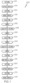
- the method 200 includes exposing 210 the outside surface 104 of the test specimen 102 to a medium, such as the first environment 122, for a predetermined period of time.
- the first environment 122 has a first temperature T 1 , a first pressure P 1 and a first composition C 1 .
- the first temperature T 1 may be selectively controlled via any means of heating based upon desired testing conditions.
- the first temperature T 1 is about 800 °C to about 1000 °C.
- the first environment 122 is ambient air or inert gas.
- the first pressure P 1 may be selectively controlled via any means of pressurizing based upon desired testing conditions, including a plurality of valves 180, see FIG. 3 , and manifolds.
- the first pressure P 1 is ambient or inert such that it is a medium.
- the first pressure P 1 is about 15 psi to about 2500 psi. in another example, the first pressure P 1 is about 1500 psi to about 2500 psi.
- Each valve 182 of the plurality of valves 180 may be individually adjustable based upon desired testing parameters.
- the first environment 122 may include any fluid.
- the first environment 122 includes an inert gas.
- the first environment 122 comprises at least one of nitrogen and oxygen.
- the first environment 122 comprises a supercritical fluid.
- the supercritical fluid may include carbon dioxide.
- the first environment 122 may include any fluid that yields an acidic pH.
- the method 200 includes exposing 220 the inside surface 108 of the test specimen 102 to a medium, for example to the second environment 124, for a second predetermined period of time.
- the second environment 124 has a second temperature T 2 , a second pressure P 2 and a second composition C 2 .
- the second temperature T 2 may be selectively controlled via any means of heating based upon desired testing conditions. In one or more examples, the second temperature T 2 is about 800 °C to about 1000 °C.
- the second pressure P 2 may be selectively controlled via any means of pressurizing based upon desired testing conditions, including a second plurality of valves 184, see FIG. 3 , and manifolds.
- the second pressure P 2 may be the same as the first pressure P 1 or may be different than the first pressure P 1 . In one or more examples, the second pressure P 2 is about 1500 psi to about 2500 psi.
- Each valve 186 of the second plurality of valves 184 may be individually adjustable based upon desired testing parameters.
- the second environment 124 may include any fluid.
- the second environment 124 includes an inert gas.
- the second environment 124 includes at least one of nitrogen and oxygen.
- the second environment 124 includes a supercritical fluid.
- the supercritical fluid may include carbon dioxide.
- the second environment 124 includes a fluid that yields an acidic pH.
- the first environment 122 and the second environment 124 have the first composition C 1 and the second composition C 2 , respectively, which may be defined by any fluid present in each environment.
- the first composition C 1 is different from the second composition C 2 .
- the first composition C 1 may be provided via a first fluid source 140 and may be selectively controlled via first pressure control apparatus 142, FIG. 2 .
- the test specimen 102 may include any material, including metallic, ceramic, and composite materials.
- the test specimen 102 includes a refractory alloy.
- the test specimen 102 includes a nickel-based superalloy.
- the test specimen 102 includes a ceramic material.
- the test specimen 102 includes HAYNES 282 alloy.
- the test specimen 102 is tapered.
- Wall thickness of the test specimen 102 is representative of the manufacturing process.
- the test specimen 102 may have a first thickness, the first thickness is representative of the wall thickness of the portions for testing and adding fidelity to the properties of the material.
- the test specimen 102 may further have a second thickness to ensure that there is not failure outside the furnace (thick enough to not to fail) but thin enough to limit the heat exchange.
- the first thickness is about 10 to 20 thousandths of an inch, and the second thickness is at least 40 thousandths of an inch.
- the test specimen 102 has a wall thickness of about 0.01 inches to about 0.020 inches, such as from about 0.01 inches to about 0.014 inches.
- the test specimen 102 may be about 8" long and have an outside diameter of about 0.65" and an inside diameter of about 0.4".
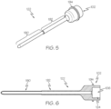
- the test specimen 102 has a testing portion or gauge length 190, see FIG. 5 and FIG. 6 , that may be about 2" to about 3" in length and have a wall thickness of about 0.020 inches.
- the test specimen 102 may further have a mid-portion 192 that is about 3" to about 4" in length and has a greater wall thickness than the wall thickness of the testing portion or gauge length 190.
- the geometry of the test specimen 102 may be comparable to that of a part manufactured by additive manufacturing.
- the amount of second pressure P 2 introduced may be a function of the geometry of the test specimen 102. For example, a range of about 13 KSI to about 21 KSI may be interested when the test specimen 102 has an inner diameter of about 0.25". In another example, a range of about 20 KSI to about 30 KSI may be interested when the test specimen 102 has an inner diameter of about 0.4". In another example, a test specimen 102 having a tin thickness of about 0.010 inches may have a second pressure P 2 of about 18 KSI to about 45 KSI. Other factors may determine wall thickness of the test specimen 102, such as oxygen diffusion rate.
- the first predetermined time and the second predetermined time may be any desired time for testing under desired conditions.
- the first predetermined time is at least 1000 hours and the second predetermined time is at least 1000 hours.
- the method 200 may further include coupling 250 a mechanical load 125 to the test specimen 102 during the exposing 210 the outside surface 104 of the test specimen 102 and the exposing 220 the inside surface 108 of the test specimen 102.
- the coupling 250 may be performed to further test the test specimen 102 for strength-related material properties when exposed to various corrosive and extreme environments.
- the method 200 may further include collecting 230 a sample 232 from the first environment 122.
- the sample 232 may be drawn from the first environment 122 at any point during testing.
- the method 200 may further include qualitative testing 235 the sample 232 from the first environment 122.
- the qualitative testing 235 may determine if any reactions have occurred in the first environment 122 due to the combined conditions of the first composition C 1 , first temperature T 1 , first pressure P 1 , and the composition of the test specimen 102.
- the method 200 further includes collecting 240 a sample 242 from the second environment 124. Additionally, after the collecting 240, the method 200 includes qualitative testing 245 the sample 242 from the second environment 124. The qualitative testing 245 may determine if any reactions have occurred in second environment 124 due to the combined conditions of the second composition C 2 , second temperature T 2 , second pressure P 2 , and the composition of the test specimen 102.
- the method 200 may be implemented with more than one test specimen 102.
- the method 200 may include exposing 260 an outside surface 104' of a second test specimen 102' to the first environment 122 for a predetermined period of time.
- the method 200 may further include exposing 270 an inside surface 108' of the second test specimen 102' to a third environment 126 for a predetermined period of time, the third environment 126 having a third temperature T 3 , a third pressure P 3 and a third composition C 3 .
- the exposing 210 the outside surface 104 of the test specimen 102 and the exposing 260 the outside surface 104' of the second test specimen 102' are performed concurrently.
- the second composition C2 may be different from the third composition C3.
- the test specimen 102 and the second test specimen 102' may include any materials selected for a particular test and may be of the same composition. In one example, the test specimen 102 and the second test specimen 102' are compositionally different. Further, the test specimen 102 and the second test specimen 102' may both be metallic or ceramic or, alternatively, one of the test specimen 102 and the second test specimen 102' may be metallic and the other ceramic.
- the test specimen 102 may include any desired material and may be of any shape and configuration that defines an internal volume.
- the test specimen 102 comprises a refractory alloy.
- the test specimen 102 comprises a nickel-based superalloy.
- the test specimen 102 comprises a ceramic.
- the test specimen 102 comprises a composite material.
- the test specimen 102 is tapered, see FIG. 5 and FIG. 6 .
- the first environment 122 has a first fluid having a first composition C 1 at a first temperature T 1 and a first pressure P 1
- the second environment 124 has a second fluid having a second composition C 2 at a second temperature T 2 and a second pressure P 2
- the test specimen 102 has an outside surface 104 to be exposed to the first environment 122 and an inside surface 108 to be exposed to the second environment 124.
- the inside surface 108 of the test specimen 102 defines an internal volume 106 of the test specimen 102, see FIG. 6 .
- the first composition C 1 is different from the second composition C 2 .
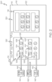
- the system 100 includes a housing 110, see FIG. 2 and FIG. 3 .
- the housing 110 defines a chamber 112.
- the chamber 112 is configured to receive at least one test specimen 102.
- the housing 110 is an autoclave.
- the system 100 may further include a pressure relief port 114 fluidly coupled with the chamber 112 of the housing 110.
- the system 100 includes a first fluid source 140.
- the first fluid source 140 is fluidly coupled with the chamber 112 of the housing 110 and configured to supply the first fluid to the chamber 112.
- the first fluid source 140 comprises at least one of nitrogen and oxygen to provide the first environment 122 with at least one of nitrogen and oxygen.
- the first fluid source 140 comprises ambient air.
- the first fluid source 140 comprises an inert gas.
- the first fluid source 140 comprises a supercritical fluid to provide the first environment 122 with a supercritical fluid.
- the supercritical fluid may include carbon dioxide.
- the first fluid source 140 comprises a fluid that yields an acidic pH in the first environment 122.
- the system 100 further includes a first pressure control apparatus 142 associated with the first fluid source 140, FIG. 2 .
- the first pressure control apparatus 142 is configured to control, at least partially, the first pressure P 1 of the first fluid.
- the first pressure P 1 is about 1500 psi to about 2500 psi.
- the first pressure control apparatus 142 is couplable with the first fluid source 140.
- the system 100 further includes a second fluid source 144 fluidly couplable with the internal volume 106 of the test specimen 102 to supply the second fluid to the internal volume 106 of the test specimen 102.
- the first fluid source 140 and the second fluid source 144 are one and the same.
- the second fluid source 144 may include any fluid needed to desired testing parameters.
- the second fluid source 144 comprises an inert gas to provide the second environment 124 with an inert gas.
- the second fluid source 144 comprises at least one of nitrogen and oxygen to provide the second environment 124 with at least one of nitrogen and oxygen.
- the second fluid source 144 comprises a supercritical fluid to provide the second environment 124 with a supercritical fluid.
- the supercritical fluid may include carbon dioxide.
- the second fluid source 144 comprises a fluid that yields an acidic pH in the second environment 124.
- the system 100 further includes a second pressure control apparatus 146 associated with the second fluid source 144, FIG. 2 .
- the second pressure control apparatus 146 is configured to control, at least partially, the second pressure P 2 of the second fluid.
- the second pressure P 2 is about 1500 psi to about 2500 psi.
- the first pressure P 1 is different than the second pressure P 2 .
- the system 100 includes a heat source 150 located in the housing 110.
- the heat source 150 defines a heated chamber 152 for receiving the test specimen 102.
- the heated chamber 152 is configured to control, at least partially, the first temperature T 1 of the first fluid and the second temperature T 2 of the second fluid.
- the heat source 150 may be a furnace.
- the temperature of the furnace may be automated such that it automatically assumes a desired temperature or may be manually adjusted to a desired temperature.
- the first temperature T 1 may be about 800 °C to about 1000 °C.
- the second temperature T 2 is about 800 °C to about 1000 °C.
- the first temperature T 1 may be different than the second temperature T 2 .
- first temperature T 1 may be at least 100 °C different than the second temperature T 2 .
- the system 100 may further include a second heat source 130 located in the housing 110.
- the second heat source 130 is a furnace.
- the second heat source 130 may include a plurality of test specimens 116 disposed therein, see FIG. 4 .
- the second heat source 130 may have a first temperature T 1 1 of the second heat source 130, a first pressure P 1 1 of the second heat source 130, and a first composition C 1 1 of the second heat source 130.
- the system 100 may further include a sample collection apparatus 160.
- the sample collection apparatus 160 is fluidly coupled with the first environment 122 such that it is configured to draw fluid from the first environment 122 for testing.
- the sample collection apparatus 160 may also be fluidly coupled with the second environment 124 such that it is configured to draw fluid from the second environment 124 for testing.
- the system 100 further includes a mechanical load 125 couplable with the test specimen 102.
- the system 100 may include more than one mechanical load 125, each being coupled with a test specimen 102 of a plurality of test specimens 116.
- each mechanical load 125 coupled with the plurality of test specimens 116 is the same weight.
- the system 100 may include at least one sensor to monitor environmental conditions.
- the system 100 includes a carbon dioxide sensor 170 in the chamber 112 of the housing 110.
- the system 100 includes a temperature sensor 172 in the chamber 112 of the housing 110.
- the system 100 includes a pressure sensor 174 in the chamber 112 of the housing 110.
- service method 1100 may include specification and design (block 1104) of aircraft 1102 and material procurement (Block 1106).
- component and subassembly manufacturing (Block 1108) and system integration (Block 1110) of aircraft 1102 may take place.
- aircraft 1102 may go through certification and delivery (Block 1112) to be placed in service (Block 1114).
- aircraft 1102 may be scheduled for routine maintenance and service (Block 1116). Routine maintenance and service may include modification, reconfiguration, refurbishment, etc. of one or more systems of aircraft 1102.
- Each of the processes of service method 1100 may be performed or carried out by a system integrator, a third party, and/or an operator (e.g., a customer).
- a system integrator may include, without limitation, any number of aircraft manufacturers and major-system subcontractors
- a third party may include, without limitation, any number of vendors, subcontractors, and suppliers
- an operator may be an airline, leasing company, military entity, service organization, and so on.
- aircraft 1102 produced by service method 1100 may include airframe 1118 with a plurality of high-level systems 1120 and interior 1122.
- high-level systems 1120 include one or more of propulsion system 1124, electrical system 1126, hydraulic system 1128, and environmental system 1130. Any number of other systems may be included.
- propulsion system 1124 one or more of propulsion system 1124, electrical system 1126, hydraulic system 1128, and environmental system 1130. Any number of other systems may be included.
- propulsion system 1124 include one or more of propulsion system 1124, electrical system 1126, hydraulic system 1128, and environmental system 1130. Any number of other systems may be included.
- an aerospace example is shown, the principles disclosed herein may be applied to other industries, such as the automotive industry. Accordingly, in addition to aircraft 1102, the principles disclosed herein may apply to other vehicles, e.g., land vehicles, marine vehicles, space vehicles, etc.
- System(s) and method(s) shown or described herein may be employed during any one or more of the stages of the manufacturing and service method 1100.
- components or subassemblies corresponding to component and subassembly manufacturing (block 1108) may be fabricated or manufactured in a manner similar to components or subassemblies produced while aircraft 1102 is in service (Block 1114).
- one or more examples of the system(s), method(s), or combination thereof may be utilized during production stages component and subassembly manufacturing (Block 1108) and system integration (Block 1110), for example, by substantially expediting assembly of or reducing the cost of aircraft 1102.
- one or more examples of the system or method realizations, or a combination thereof may be utilized, for example and without limitation, while aircraft 1102 is in service (Block 1114) and/or during maintenance and service (Block 1116).
Landscapes
- Life Sciences & Earth Sciences (AREA)
- Physics & Mathematics (AREA)
- General Physics & Mathematics (AREA)
- Immunology (AREA)
- General Health & Medical Sciences (AREA)
- Pathology (AREA)
- Health & Medical Sciences (AREA)
- Chemical & Material Sciences (AREA)
- Analytical Chemistry (AREA)
- Biochemistry (AREA)
- Environmental Sciences (AREA)
- Ecology (AREA)
- Biodiversity & Conservation Biology (AREA)
- Environmental & Geological Engineering (AREA)
- Engineering & Computer Science (AREA)
- Manufacturing & Machinery (AREA)
- Transportation (AREA)
- Aviation & Aerospace Engineering (AREA)
- Testing Resistance To Weather, Investigating Materials By Mechanical Methods (AREA)
Applications Claiming Priority (1)
| Application Number | Priority Date | Filing Date | Title |
|---|---|---|---|
| US17/673,085 US12111330B2 (en) | 2022-02-16 | 2022-02-16 | Systems and methods for concurrently exposing a test specimen to a first environment and a second environment |
Publications (3)
| Publication Number | Publication Date |
|---|---|
| EP4242633A2 true EP4242633A2 (de) | 2023-09-13 |
| EP4242633A3 EP4242633A3 (de) | 2023-11-08 |
| EP4242633B1 EP4242633B1 (de) | 2025-12-10 |
Family
ID=83593857
Family Applications (1)
| Application Number | Title | Priority Date | Filing Date |
|---|---|---|---|
| EP22199493.2A Active EP4242633B1 (de) | 2022-02-16 | 2022-10-04 | System und verfahren zur gleichzeitigen exposition einer testprobe an eine erste umgebung und eine zweite umgebung |
Country Status (3)
| Country | Link |
|---|---|
| US (1) | US12111330B2 (de) |
| EP (1) | EP4242633B1 (de) |
| CN (1) | CN116609245A (de) |
Families Citing this family (1)
| Publication number | Priority date | Publication date | Assignee | Title |
|---|---|---|---|---|
| US20260043735A1 (en) * | 2024-08-09 | 2026-02-12 | The Boeing Company | Test fixtures and methods for improving fidelity of thermal oxidative stability testing |
Family Cites Families (13)
| Publication number | Priority date | Publication date | Assignee | Title |
|---|---|---|---|---|
| US5260218A (en) * | 1990-10-29 | 1993-11-09 | Combustion Engineering, Inc. | Autoclave corrosion test for zirconium alloys |
| WO2001069223A2 (en) * | 2000-03-14 | 2001-09-20 | British Nuclear Fuels Plc | Method and apparatus for investigating corrosion |
| US20040056654A1 (en) | 2002-05-21 | 2004-03-25 | Jentek Sensors, Inc. | Magnetic field characterization of stresses and properties in materials |
| US7704324B2 (en) | 2005-01-25 | 2010-04-27 | General Electric Company | Apparatus for processing materials in supercritical fluids and methods thereof |
| US8209133B2 (en) | 2007-08-16 | 2012-06-26 | Board Of Supervisors Of Louisiana State University And Agricultural And Mechanical College | Rapid determination of fatigue failure based on temperature evolution |
| US8521445B2 (en) * | 2009-09-17 | 2013-08-27 | Conocophillips Company | Corrosion rate monitoring |
| US8474324B2 (en) * | 2011-11-30 | 2013-07-02 | King Fahd University Of Petroleum And Minerals | Stress corrosion cracking testing device |
| KR101440554B1 (ko) | 2013-05-10 | 2014-09-17 | 재단법인 포항산업과학연구원 | 해수부식 피로시험 시스템 |
| JP6153501B2 (ja) * | 2014-07-17 | 2017-06-28 | エスペック株式会社 | 環境試験装置及び環境試験方法 |
| US9429510B2 (en) * | 2014-11-18 | 2016-08-30 | General Electric Company | Corrosion sensor for internal structure of machine |
| EP3411708A1 (de) * | 2016-02-01 | 2018-12-12 | Quipip, LLC | Erfassungsvorrichtung, erfassungsvorrichtungssystem und verfahren zum messen einer eigenschaft einer betonmischung und zur vorhersage einer leistungseigenschaft einer betonmischung |
| KR101636692B1 (ko) * | 2016-06-17 | 2016-07-06 | 주식회사 신한이엔지 | 통합시험장치 |
| CN108593198A (zh) | 2018-04-23 | 2018-09-28 | 武汉华星光电技术有限公司 | 电容式隔膜真空计及干刻蚀设备腔体压力测试系统 |
-
2022
- 2022-02-16 US US17/673,085 patent/US12111330B2/en active Active
- 2022-10-04 EP EP22199493.2A patent/EP4242633B1/de active Active
- 2022-12-15 CN CN202211618781.1A patent/CN116609245A/zh active Pending
Also Published As
| Publication number | Publication date |
|---|---|
| EP4242633A3 (de) | 2023-11-08 |
| US12111330B2 (en) | 2024-10-08 |
| EP4242633B1 (de) | 2025-12-10 |
| US20230258484A1 (en) | 2023-08-17 |
| CN116609245A (zh) | 2023-08-18 |
Similar Documents
| Publication | Publication Date | Title |
|---|---|---|
| EP4242633A2 (de) | System und verfahren zur gleichzeitigen exposition einer testprobe an eine erste umgebung und eine zweite umgebung | |
| CN108204938B (zh) | 一种阻氚涂层中氢扩散渗透性能测定装置 | |
| Katsivalis et al. | Hydrogen permeability of thin-ply composites after mechanical loading | |
| Ellyin et al. | Testing facilities for multiaxial loading of tubular specimens | |
| CN110926972A (zh) | 微动疲劳表面裂纹检测方法及系统 | |
| CN112326472B (zh) | 一种高温环境疲劳试验装置 | |
| CN115219360A (zh) | 原位多轴蠕变疲劳测试装置 | |
| Yu et al. | Failure modeling of SiC/SiC mini-composites in air oxidizing environments | |
| Panigrahi et al. | Experimental evaluation of overload capability of an annular combustor casing of a gas turbine engine | |
| US20260043735A1 (en) | Test fixtures and methods for improving fidelity of thermal oxidative stability testing | |
| US9091618B1 (en) | Gas sampling system | |
| CN119147438B (zh) | 金属支撑件、基于其的非金属材料气体渗透性能参数测试装置及修正方法 | |
| Koh et al. | Fundamental study of transpiration cooling | |
| Bechel et al. | Through-laminate damage in cryogenically cycled polymer composites | |
| Waller et al. | Qualification of products fabricated via additive manufacturing using nondestructive evaluation | |
| Boettner | Experimental Analysis of Cryogenic Hydrogen Leakage in Additively Manufactured Hydrogen Tanks | |
| MacDonald et al. | Carbon Growth Chamber: Development and Operation | |
| Gangloff et al. | Low cost glass-ceramic matrix composites for harsh environment heat exchanger applications | |
| Brockmeyer et al. | Fiber-reinforced ceramic composites for Earth-to-orbit rocket engine turbines | |
| Katoh et al. | Determination of He and D permeability of neutron-irradiated SiC tubes to examine the potential for release due to micro-cracking | |
| Saturn et al. | Benefit | |
| Martinez et al. | Lessons learned from the design, certification, and operation of the space shuttle integrated main propulsion system (IMPS) | |
| HODGE | The Langley 15-inch Mach 6 High Temperature Tunnel | |
| Parker | Structural evaluation of the inner reflector | |
| Waller et al. | ASTM E07 Committee on Nondestructive Testing Activities |
Legal Events
| Date | Code | Title | Description |
|---|---|---|---|
| PUAI | Public reference made under article 153(3) epc to a published international application that has entered the european phase |
Free format text: ORIGINAL CODE: 0009012 |
|
| STAA | Information on the status of an ep patent application or granted ep patent |
Free format text: STATUS: THE APPLICATION HAS BEEN PUBLISHED |
|
| AK | Designated contracting states |
Kind code of ref document: A2 Designated state(s): AL AT BE BG CH CY CZ DE DK EE ES FI FR GB GR HR HU IE IS IT LI LT LU LV MC ME MK MT NL NO PL PT RO RS SE SI SK SM TR |
|
| PUAL | Search report despatched |
Free format text: ORIGINAL CODE: 0009013 |
|
| AK | Designated contracting states |
Kind code of ref document: A3 Designated state(s): AL AT BE BG CH CY CZ DE DK EE ES FI FR GB GR HR HU IE IS IT LI LT LU LV MC ME MK MT NL NO PL PT RO RS SE SI SK SM TR |
|
| RIC1 | Information provided on ipc code assigned before grant |
Ipc: G01N 17/00 20060101AFI20231002BHEP |
|
| STAA | Information on the status of an ep patent application or granted ep patent |
Free format text: STATUS: REQUEST FOR EXAMINATION WAS MADE |
|
| 17P | Request for examination filed |
Effective date: 20240424 |
|
| RBV | Designated contracting states (corrected) |
Designated state(s): AL AT BE BG CH CY CZ DE DK EE ES FI FR GB GR HR HU IE IS IT LI LT LU LV MC ME MK MT NL NO PL PT RO RS SE SI SK SM TR |
|
| GRAP | Despatch of communication of intention to grant a patent |
Free format text: ORIGINAL CODE: EPIDOSNIGR1 |
|
| STAA | Information on the status of an ep patent application or granted ep patent |
Free format text: STATUS: GRANT OF PATENT IS INTENDED |
|
| INTG | Intention to grant announced |
Effective date: 20250908 |
|
| GRAS | Grant fee paid |
Free format text: ORIGINAL CODE: EPIDOSNIGR3 |
|
| GRAA | (expected) grant |
Free format text: ORIGINAL CODE: 0009210 |
|
| STAA | Information on the status of an ep patent application or granted ep patent |
Free format text: STATUS: THE PATENT HAS BEEN GRANTED |
|
| AK | Designated contracting states |
Kind code of ref document: B1 Designated state(s): AL AT BE BG CH CY CZ DE DK EE ES FI FR GB GR HR HU IE IS IT LI LT LU LV MC ME MK MT NL NO PL PT RO RS SE SI SK SM TR |
|
| P01 | Opt-out of the competence of the unified patent court (upc) registered |
Free format text: CASE NUMBER: UPC_APP_0012326_4242633/2025 Effective date: 20251105 |
|
| REG | Reference to a national code |
Ref country code: CH Ref legal event code: F10 Free format text: ST27 STATUS EVENT CODE: U-0-0-F10-F00 (AS PROVIDED BY THE NATIONAL OFFICE) Effective date: 20251210 Ref country code: GB Ref legal event code: FG4D |
|
| REG | Reference to a national code |
Ref country code: DE Ref legal event code: R096 Ref document number: 602022026484 Country of ref document: DE |
|
| REG | Reference to a national code |
Ref country code: IE Ref legal event code: FG4D |
|
| PG25 | Lapsed in a contracting state [announced via postgrant information from national office to epo] |
Ref country code: ES Free format text: LAPSE BECAUSE OF FAILURE TO SUBMIT A TRANSLATION OF THE DESCRIPTION OR TO PAY THE FEE WITHIN THE PRESCRIBED TIME-LIMIT Effective date: 20251210 |
|
| REG | Reference to a national code |
Ref country code: LT Ref legal event code: MG9D |
|
| PG25 | Lapsed in a contracting state [announced via postgrant information from national office to epo] |
Ref country code: NO Free format text: LAPSE BECAUSE OF FAILURE TO SUBMIT A TRANSLATION OF THE DESCRIPTION OR TO PAY THE FEE WITHIN THE PRESCRIBED TIME-LIMIT Effective date: 20260310 |
|
| PG25 | Lapsed in a contracting state [announced via postgrant information from national office to epo] |
Ref country code: HR Free format text: LAPSE BECAUSE OF FAILURE TO SUBMIT A TRANSLATION OF THE DESCRIPTION OR TO PAY THE FEE WITHIN THE PRESCRIBED TIME-LIMIT Effective date: 20251210 Ref country code: FI Free format text: LAPSE BECAUSE OF FAILURE TO SUBMIT A TRANSLATION OF THE DESCRIPTION OR TO PAY THE FEE WITHIN THE PRESCRIBED TIME-LIMIT Effective date: 20251210 |
|
| REG | Reference to a national code |
Ref country code: NL Ref legal event code: MP Effective date: 20251210 |
|
| PG25 | Lapsed in a contracting state [announced via postgrant information from national office to epo] |
Ref country code: RS Free format text: LAPSE BECAUSE OF FAILURE TO SUBMIT A TRANSLATION OF THE DESCRIPTION OR TO PAY THE FEE WITHIN THE PRESCRIBED TIME-LIMIT Effective date: 20260310 |
|
| PG25 | Lapsed in a contracting state [announced via postgrant information from national office to epo] |
Ref country code: LV Free format text: LAPSE BECAUSE OF FAILURE TO SUBMIT A TRANSLATION OF THE DESCRIPTION OR TO PAY THE FEE WITHIN THE PRESCRIBED TIME-LIMIT Effective date: 20251210 |