EP4242410A2 - Fenêtre transparente aux micro-ondes à efficacité énergétique compatible avec la présente conception - Google Patents
Fenêtre transparente aux micro-ondes à efficacité énergétique compatible avec la présente conception Download PDFInfo
- Publication number
- EP4242410A2 EP4242410A2 EP23188301.8A EP23188301A EP4242410A2 EP 4242410 A2 EP4242410 A2 EP 4242410A2 EP 23188301 A EP23188301 A EP 23188301A EP 4242410 A2 EP4242410 A2 EP 4242410A2
- Authority
- EP
- European Patent Office
- Prior art keywords
- glass layer
- glass
- window structure
- gigahertz
- frequency
- Prior art date
- Legal status (The legal status is an assumption and is not a legal conclusion. Google has not performed a legal analysis and makes no representation as to the accuracy of the status listed.)
- Pending
Links
- 238000013461 design Methods 0.000 title description 13
- 239000011521 glass Substances 0.000 claims abstract description 404
- 238000000576 coating method Methods 0.000 claims abstract description 122
- BJQHLKABXJIVAM-UHFFFAOYSA-N bis(2-ethylhexyl) phthalate Chemical compound CCCCC(CC)COC(=O)C1=CC=CC=C1C(=O)OCC(CC)CCCC BJQHLKABXJIVAM-UHFFFAOYSA-N 0.000 claims abstract description 99
- 239000011248 coating agent Substances 0.000 claims description 59
- 238000002310 reflectometry Methods 0.000 claims description 48
- 239000005361 soda-lime glass Substances 0.000 claims description 42
- 230000005855 radiation Effects 0.000 claims description 26
- 238000000034 method Methods 0.000 claims description 23
- 230000035699 permeability Effects 0.000 claims description 6
- 239000010410 layer Substances 0.000 description 289
- 230000005540 biological transmission Effects 0.000 description 33
- 230000006870 function Effects 0.000 description 20
- 239000007789 gas Substances 0.000 description 12
- 230000008901 benefit Effects 0.000 description 11
- 239000000853 adhesive Substances 0.000 description 9
- 230000001070 adhesive effect Effects 0.000 description 9
- 230000003595 spectral effect Effects 0.000 description 9
- 238000007499 fusion processing Methods 0.000 description 6
- 230000001965 increasing effect Effects 0.000 description 6
- 230000009467 reduction Effects 0.000 description 6
- 230000004044 response Effects 0.000 description 5
- BQCADISMDOOEFD-UHFFFAOYSA-N Silver Chemical compound [Ag] BQCADISMDOOEFD-UHFFFAOYSA-N 0.000 description 4
- 230000006872 improvement Effects 0.000 description 4
- 239000006060 molten glass Substances 0.000 description 4
- 238000012545 processing Methods 0.000 description 4
- 229910052709 silver Inorganic materials 0.000 description 4
- 239000004332 silver Substances 0.000 description 4
- 238000001228 spectrum Methods 0.000 description 4
- 230000002238 attenuated effect Effects 0.000 description 3
- 238000005516 engineering process Methods 0.000 description 3
- 229920002037 poly(vinyl butyral) polymer Polymers 0.000 description 3
- 239000002994 raw material Substances 0.000 description 3
- 230000035945 sensitivity Effects 0.000 description 3
- XKRFYHLGVUSROY-UHFFFAOYSA-N Argon Chemical compound [Ar] XKRFYHLGVUSROY-UHFFFAOYSA-N 0.000 description 2
- 239000003513 alkali Substances 0.000 description 2
- 239000002585 base Substances 0.000 description 2
- 230000009286 beneficial effect Effects 0.000 description 2
- 239000004566 building material Substances 0.000 description 2
- 238000013016 damping Methods 0.000 description 2
- 238000010586 diagram Methods 0.000 description 2
- 239000011261 inert gas Substances 0.000 description 2
- 238000000411 transmission spectrum Methods 0.000 description 2
- 108700019404 Pro-Gly-Pro- ACTH (4-7) Proteins 0.000 description 1
- 238000010521 absorption reaction Methods 0.000 description 1
- 229910052786 argon Inorganic materials 0.000 description 1
- 238000004364 calculation method Methods 0.000 description 1
- 230000010267 cellular communication Effects 0.000 description 1
- 230000001413 cellular effect Effects 0.000 description 1
- 230000008859 change Effects 0.000 description 1
- 230000001427 coherent effect Effects 0.000 description 1
- 238000004891 communication Methods 0.000 description 1
- 230000001143 conditioned effect Effects 0.000 description 1
- 230000001419 dependent effect Effects 0.000 description 1
- 238000000151 deposition Methods 0.000 description 1
- 230000000694 effects Effects 0.000 description 1
- 230000002708 enhancing effect Effects 0.000 description 1
- 230000001747 exhibiting effect Effects 0.000 description 1
- 229910010272 inorganic material Inorganic materials 0.000 description 1
- 239000011147 inorganic material Substances 0.000 description 1
- 230000003993 interaction Effects 0.000 description 1
- -1 low-E coatings Substances 0.000 description 1
- 238000004519 manufacturing process Methods 0.000 description 1
- 239000000463 material Substances 0.000 description 1
- 230000007246 mechanism Effects 0.000 description 1
- 238000002844 melting Methods 0.000 description 1
- 230000008018 melting Effects 0.000 description 1
- 239000000203 mixture Substances 0.000 description 1
- 230000003287 optical effect Effects 0.000 description 1
- 238000004806 packaging method and process Methods 0.000 description 1
- 230000035515 penetration Effects 0.000 description 1
- 230000008569 process Effects 0.000 description 1
- 238000011002 quantification Methods 0.000 description 1
- 239000004576 sand Substances 0.000 description 1
- AFEHBIGDWIGTEH-AQRCPPRCSA-N semax Chemical compound C([C@H](NC(=O)[C@H](CCC(O)=O)NC(=O)[C@@H](N)CCSC)C(=O)N[C@@H](CC=1C=CC=CC=1)C(=O)N1[C@@H](CCC1)C(=O)NCC(=O)N1[C@@H](CCC1)C(O)=O)C1=CNC=N1 AFEHBIGDWIGTEH-AQRCPPRCSA-N 0.000 description 1
- 239000002356 single layer Substances 0.000 description 1
- 239000000758 substrate Substances 0.000 description 1
- 238000005496 tempering Methods 0.000 description 1
- 238000012546 transfer Methods 0.000 description 1
- 238000002834 transmittance Methods 0.000 description 1
- XLYOFNOQVPJJNP-UHFFFAOYSA-N water Substances O XLYOFNOQVPJJNP-UHFFFAOYSA-N 0.000 description 1
Images


Classifications
-
- C—CHEMISTRY; METALLURGY
- C03—GLASS; MINERAL OR SLAG WOOL
- C03C—CHEMICAL COMPOSITION OF GLASSES, GLAZES OR VITREOUS ENAMELS; SURFACE TREATMENT OF GLASS; SURFACE TREATMENT OF FIBRES OR FILAMENTS MADE FROM GLASS, MINERALS OR SLAGS; JOINING GLASS TO GLASS OR OTHER MATERIALS
- C03C17/00—Surface treatment of glass, not in the form of fibres or filaments, by coating
- C03C17/34—Surface treatment of glass, not in the form of fibres or filaments, by coating with at least two coatings having different compositions
- C03C17/36—Surface treatment of glass, not in the form of fibres or filaments, by coating with at least two coatings having different compositions at least one coating being a metal
- C03C17/3602—Surface treatment of glass, not in the form of fibres or filaments, by coating with at least two coatings having different compositions at least one coating being a metal the metal being present as a layer
- C03C17/3681—Surface treatment of glass, not in the form of fibres or filaments, by coating with at least two coatings having different compositions at least one coating being a metal the metal being present as a layer the multilayer coating being used in glazing, e.g. windows or windscreens
-
- G—PHYSICS
- G02—OPTICS
- G02B—OPTICAL ELEMENTS, SYSTEMS OR APPARATUS
- G02B5/00—Optical elements other than lenses
- G02B5/20—Filters
- G02B5/28—Interference filters
- G02B5/285—Interference filters comprising deposited thin solid films
- G02B5/288—Interference filters comprising deposited thin solid films comprising at least one thin film resonant cavity, e.g. in bandpass filters
-
- C—CHEMISTRY; METALLURGY
- C03—GLASS; MINERAL OR SLAG WOOL
- C03C—CHEMICAL COMPOSITION OF GLASSES, GLAZES OR VITREOUS ENAMELS; SURFACE TREATMENT OF GLASS; SURFACE TREATMENT OF FIBRES OR FILAMENTS MADE FROM GLASS, MINERALS OR SLAGS; JOINING GLASS TO GLASS OR OTHER MATERIALS
- C03C17/00—Surface treatment of glass, not in the form of fibres or filaments, by coating
- C03C17/06—Surface treatment of glass, not in the form of fibres or filaments, by coating with metals
-
- C—CHEMISTRY; METALLURGY
- C03—GLASS; MINERAL OR SLAG WOOL
- C03C—CHEMICAL COMPOSITION OF GLASSES, GLAZES OR VITREOUS ENAMELS; SURFACE TREATMENT OF GLASS; SURFACE TREATMENT OF FIBRES OR FILAMENTS MADE FROM GLASS, MINERALS OR SLAGS; JOINING GLASS TO GLASS OR OTHER MATERIALS
- C03C17/00—Surface treatment of glass, not in the form of fibres or filaments, by coating
- C03C17/34—Surface treatment of glass, not in the form of fibres or filaments, by coating with at least two coatings having different compositions
- C03C17/36—Surface treatment of glass, not in the form of fibres or filaments, by coating with at least two coatings having different compositions at least one coating being a metal
- C03C17/3602—Surface treatment of glass, not in the form of fibres or filaments, by coating with at least two coatings having different compositions at least one coating being a metal the metal being present as a layer
- C03C17/3644—Surface treatment of glass, not in the form of fibres or filaments, by coating with at least two coatings having different compositions at least one coating being a metal the metal being present as a layer the metal being silver
-
- C—CHEMISTRY; METALLURGY
- C03—GLASS; MINERAL OR SLAG WOOL
- C03C—CHEMICAL COMPOSITION OF GLASSES, GLAZES OR VITREOUS ENAMELS; SURFACE TREATMENT OF GLASS; SURFACE TREATMENT OF FIBRES OR FILAMENTS MADE FROM GLASS, MINERALS OR SLAGS; JOINING GLASS TO GLASS OR OTHER MATERIALS
- C03C17/00—Surface treatment of glass, not in the form of fibres or filaments, by coating
- C03C17/34—Surface treatment of glass, not in the form of fibres or filaments, by coating with at least two coatings having different compositions
- C03C17/36—Surface treatment of glass, not in the form of fibres or filaments, by coating with at least two coatings having different compositions at least one coating being a metal
- C03C17/3602—Surface treatment of glass, not in the form of fibres or filaments, by coating with at least two coatings having different compositions at least one coating being a metal the metal being present as a layer
- C03C17/3657—Surface treatment of glass, not in the form of fibres or filaments, by coating with at least two coatings having different compositions at least one coating being a metal the metal being present as a layer the multilayer coating having optical properties
- C03C17/366—Low-emissivity or solar control coatings
-
- E—FIXED CONSTRUCTIONS
- E06—DOORS, WINDOWS, SHUTTERS, OR ROLLER BLINDS IN GENERAL; LADDERS
- E06B—FIXED OR MOVABLE CLOSURES FOR OPENINGS IN BUILDINGS, VEHICLES, FENCES OR LIKE ENCLOSURES IN GENERAL, e.g. DOORS, WINDOWS, BLINDS, GATES
- E06B3/00—Window sashes, door leaves, or like elements for closing wall or like openings; Layout of fixed or moving closures, e.g. windows in wall or like openings; Features of rigidly-mounted outer frames relating to the mounting of wing frames
- E06B3/66—Units comprising two or more parallel glass or like panes permanently secured together
- E06B3/67—Units comprising two or more parallel glass or like panes permanently secured together characterised by additional arrangements or devices for heat or sound insulation or for controlled passage of light
- E06B3/6715—Units comprising two or more parallel glass or like panes permanently secured together characterised by additional arrangements or devices for heat or sound insulation or for controlled passage of light specially adapted for increased thermal insulation or for controlled passage of light
-
- G—PHYSICS
- G02—OPTICS
- G02B—OPTICAL ELEMENTS, SYSTEMS OR APPARATUS
- G02B5/00—Optical elements other than lenses
- G02B5/20—Filters
- G02B5/28—Interference filters
- G02B5/281—Interference filters designed for the infrared light
- G02B5/282—Interference filters designed for the infrared light reflecting for infrared and transparent for visible light, e.g. heat reflectors, laser protection
-
- C—CHEMISTRY; METALLURGY
- C03—GLASS; MINERAL OR SLAG WOOL
- C03C—CHEMICAL COMPOSITION OF GLASSES, GLAZES OR VITREOUS ENAMELS; SURFACE TREATMENT OF GLASS; SURFACE TREATMENT OF FIBRES OR FILAMENTS MADE FROM GLASS, MINERALS OR SLAGS; JOINING GLASS TO GLASS OR OTHER MATERIALS
- C03C2217/00—Coatings on glass
- C03C2217/70—Properties of coatings
- C03C2217/73—Anti-reflective coatings with specific characteristics
- C03C2217/734—Anti-reflective coatings with specific characteristics comprising an alternation of high and low refractive indexes
-
- C—CHEMISTRY; METALLURGY
- C03—GLASS; MINERAL OR SLAG WOOL
- C03C—CHEMICAL COMPOSITION OF GLASSES, GLAZES OR VITREOUS ENAMELS; SURFACE TREATMENT OF GLASS; SURFACE TREATMENT OF FIBRES OR FILAMENTS MADE FROM GLASS, MINERALS OR SLAGS; JOINING GLASS TO GLASS OR OTHER MATERIALS
- C03C2218/00—Methods for coating glass
- C03C2218/30—Aspects of methods for coating glass not covered above
- C03C2218/365—Coating different sides of a glass substrate
Definitions
- Modern windows often include multiple sheets (e.g., panes) of glass. Each sheet may include a single layer of glass or multiple layers of glass that are attached using an adhesive.
- the energy efficiency of such windows may be increased by covering a surface of at least one of the sheets with a low thermal emissivity coating (a.k.a. low-E coating) and/or by filling a space between the sheets with an inert gas having relatively low thermal conductivity.
- a low thermal emissivity coating a.k.a. low-E coating
- Each low-E coating manages electromagnetic (EM) radiation that is incident on the coating.
- Low-E coatings often are metallic. For instance, silver is commonly used as a low-E coating. Accordingly, low-E coatings typically reflect frequencies that are used in cellular communications in addition to infrared frequencies that are intended to be blocked for greater energy efficiency. A low-E coating may attenuate radio waves having a frequency of greater than 1.0 GHz up to 40dB. Building materials typically allow frequencies in the range of 0.6 gigahertz (GHz) to 2.7 GHz, which are used by 3G and 4G cellular systems, to pass through. Thus, attenuations of 3G and 4G frequencies by low-E coatings in windows traditionally has not been a significant issue.
- GHz gigahertz
- 5G systems typically do not allow frequencies in the range of 6 GHz to 100 GHz, which are used by 5G systems, to pass through. Accordingly, 5G systems often require line of sight (LOS) to a receiver due to relatively low penetration through walls, foliage, etc.
- LOS line of sight
- an outside unit is likely to include the antenna and a receiver to convert centimeter-wave and millimeter-wave signals into baseband signals and to transmit them through an interconnect that may carry up to several gigabits-per-second (Gb/s) data rates. Placing such a unit outside may cause challenges with cable routing, powering the unit, and bringing the cable inside the structure.
- Gb/s gigabits-per-second
- Each of these window structures includes a Fabry-Perot etalon.
- a Fabry-Perot etalon includes a transparent layer having reflecting surfaces.
- the transparent layer may be glass, and the reflective surfaces may be formed using low-E coating(s).
- a first example window structure includes first, second, and third glass layers.
- the third glass layer is positioned between the first and second glass layers.
- the first example window structure further includes first and second low-E coatings on respective first and second opposing surfaces of the third glass layer to form a Fabry-Perot etalon that is configured as a bandpass filter having a designated frequency passband that includes at least one frequency in a range of frequencies from 6 gigahertz to 80 gigahertz.
- a second example window structure includes first, second, and third glass layers.
- Each of the first and second glass layers includes a soda-lime glass.
- the third glass layer has a first face and a second face, a thickness of less than 2.5 millimeters (mm), a thickness variation of less than 10 micrometers ( ⁇ m), and a dielectric loss tangent of less than 0.01.
- the third glass layer is positioned between the first and second glass layers to form a first cavity between the first glass layer and the third glass layer.
- the second example window structure further includes a first coating on the first face of the third glass layer and a second coating on the second face of the third glass layer.
- the first and second coatings include respective reflective low-emissive coatings.
- the third glass layer in combination with the first and second coatings form a Fabry-Perot etalon that is configured as a bandpass filter having a designated frequency passband that includes at least one frequency in a range of frequencies from 20 gigahertz to 80 gigahertz.
- infrared radiation is received at a Fabry-Perot etalon, which is formed by the third glass layer and further by first and second low-E coatings on respective first and second opposing surfaces of the third glass layer, via the first glass layer.
- the infrared radiation is attenuated using the first and second low-E coatings.
- a signal having a frequency in a range of frequencies from 6 gigahertz to 80 gigahertz is received at the Fabry-Perot etalon via the first glass layer.
- the signal is passed through the bandpass filter and the third glass layer based at least in part on the bandpass filter having a designated frequency passband that includes the frequency.
- references in the specification to "one embodiment,” “an embodiment,” “an example embodiment,” or the like, indicate that the embodiment described may include a particular feature, structure, or characteristic, but every embodiment may not necessarily include the particular feature, structure, or characteristic. Moreover, such phrases are not necessarily referring to the same embodiment. Furthermore, when a particular feature, structure, or characteristic is described in connection with an embodiment, it is submitted that it is within the knowledge of one skilled in the relevant art(s) to implement such feature, structure, or characteristic in connection with other embodiments whether or not explicitly described.
- Descriptors such as “first”, “second”, “third”, etc. are used to reference some elements discussed herein. Such descriptors are used to facilitate the discussion of the example embodiments and do not indicate a required order of the referenced elements, unless an affirmative statement is made herein that such an order is required.
- Example window structures described herein are configured to provide energy efficiency and microwave transparency.
- Each of these window structures includes a Fabry-Perot etalon.
- One example implementation of a Fabry-Perot etalon includes a transparent layer having reflecting surfaces.
- the transparent layer may be glass, and the reflective surfaces may be formed using low-E coating(s).
- Example window structures described herein have a variety of benefits as compared to conventional window structures.
- the example window structures may provide a relatively high energy efficiency (e.g., by attenuating infrared frequencies) while enabling at least some microwaves frequencies (e.g., 5G frequencies) to pass through.
- a structural design of an otherwise standard triple-pane or double-pane window may be used with as little change as possible and yet provide microwave transmission at 5G frequencies. Such microwave transmission may be provided while maintaining the full required infrared reflectivity.
- the example window structures may be capable of being fabricated using existing window processing techniques, and the Fabry-Perot etalon may be compatible with existing window structures.
- the middle pane of a triple-pane window may be fabricated to include a Fabry-Perot etalon that functions as a microwave band passband filter, or a relatively thin layer of glass that includes such a Fabry-Perot etalon may be added to one of the panes of a double-pane window.
- the Fabry-Perot can be formed using a glass layer having infrared-reflecting coatings on both of its faces.
- the Fabry-Perot etalon may be fabricated to have relatively low loss and to maintain a relatively low thickness variation of the glass layer over an entirety of a window to enable the coatings to act as mirrors for a resulting passband filter having a passband that includes one or more desired microwave frequency (e.g., a range of microwave frequencies).
- the glass layer in the Fabry-Perot etalon may be low-alkali (e.g., less than 10 mol% alkali content) or alkali-free, though the scope of the example embodiments is not limited in this respect.
- EXG TM Eagle XG
- SLG soda-lime glass
- any suitable type of glass may be used in combination with or in lieu of EXG TM glass in any of the window structures described herein.
- any of the glass layers described herein may be fabricated to have any one or more of the properties associated with EXG TM glass or none of the properties associated with EXG TM glass.
- the glass that is used to form the Fabry-Perot etalons described herein may exhibit a relatively low inherent loss for centimeter waves and/or millimeter waves.
- EXG TM glass may have a dielectric loss tangent that is approximately nine or ten times lower than the loss tangent of SLG (e.g., at 28 GHz, 37 GHz, 39 GHz, and/or 60 GHz).
- the loss tangent may be less than or equal to 0.01, 0.008, or 0.006 for a targeted frequency or a range of targeted frequencies.
- FIG. 1 is an example plot 100 of loss tangent with respect to frequency for soda-lime glass and EXG TM glass in accordance with an embodiment. As shown in FIG.
- the loss tangent of EXG TM glass is substantially less than the loss tangent of SLG across the frequency band depicted in FIG. 1 .
- the loss tangent of EXG TM glass is shown to be less than or equal to 0.01 across the frequency band.
- the glass that is used to form the Fabry-Perot etalons described herein may have a relatively low thickness variation (e.g., less than 10 ⁇ m or less than 20 ⁇ m).
- a fusion process may be used to fabricate the glass to maintain a desired thickness tolerance across an entire sheet of the glass.
- the fusion process heats raw materials (e.g., pure sand and other inorganic materials) to provide high-purity molten glass, which is formed into a sheet.
- the raw material may flow into a melting tank where the raw materials are heated (e.g., well above 1000 degrees Celsius) to provide the molten glass.
- the molten glass may be homogenized and conditioned before it is released into a collection trough with a V-shaped bottom, known as an isopipe.
- the isopipe may be heated to manage the viscosity of the mixture and maintain uniform flow.
- the molten glass may flow evenly over the top edges of the isopipe, forming two thin, sheet-like streams along the outer surfaces of the isopipe.
- the two sheets meet at the V-shaped bottom point of the isopipe and fuse into a single sheet.
- the sheet, still attached to the bottom of the isopipe, may feed into drawing equipment as it lengthens and begins to cool in midair.
- the sheet is cooled and stabilized until it reaches the bottom of the draw, where it may be cut and moved to another area to complete processing and packaging.
- Using the fusion process may eliminate a need to grind and polish the glass in order to achieve the desired thickness tolerance.
- the glass that is used to form the Fabry-Perot etalons described herein may have a relatively low dielectric constant.
- the dielectric constant may be less than five or less than six.
- the glass may have a relatively low surface flatness variation.
- the glass may be strong, cost effective, and/or serve as an excellent substrate for a Fabry-Perot insert design having microwave passband properties.
- the glass may have a relatively low coefficient of thermal expansion (CTE).
- CTE coefficient of thermal expansion
- the relatively low CTE may enable the glass to withstand thermal edge stresses in the field; whereas a thin piece of SLG may need to be thermal strengthened, which is not possible with incumbent tempering technologies for SLG having a thickness of less than 2.5 mm.
- the glass may have substantially better optical properties than SLG, which may enhance window g-value and/or visible light transmission.
- the glass may be thinner than glass layers that are traditionally used in window structures, which may reduce the weight of such window structures and/or increase the width of any cavities that are formed between the glass and other glass layers (e.g., thereby improving solar performance). Conventional coatings may be used to form the Fabry-Perot etalon, which may facilitate maintaining a relatively low cost for the window structure.
- FIG. 2 shows a cross-section of an example triple-pane window structure 200 that includes a Fabry-Perot etalon 226 in accordance with an embodiment.
- the window structure 200 includes a first pane 202, a second pane 204, and a third pane 206.
- the third pane 206 is positioned between the first pane 202 and the second pane 204.
- a first cavity 208 is formed between the first pane 202 and the third pane 206.
- a second cavity 210 is formed between the second pane 204 and the third pane 206.
- Each of the first and second cavities 208 and 210 may be filled with a gas (e.g., an inert gas).
- a gas e.g., an inert gas
- the gas may have a relatively low thermal conductivity (e.g., less than 20 milliwatts per meter K (mW / m K) at 300 K) to help increase energy efficiency of the window structure 200.
- the gas may be Argon, which is known to have a thermal conductivity of 18 mW / m K at 300 K.
- Each of the first and second cavities 208 and 210 may be sealed.
- the first pane 202 includes a first glass layer 212.
- the second pane 204 includes a second glass layer 214 and a fourth glass layer 218, which are attached using an adhesive 220.
- the adhesive 220 may be polyvinyl butyral, for example.
- the third pane 206 includes a third glass layer 216.
- the third glass layer 216 has first and second opposing surfaces, which face the respective first and second cavities 208 and 210.
- a first low-E coating 222 is on the first surface of the third glass layer 216.
- a second low-E coating 224 is on the second surface of the third glass layer 216.
- the first low-E coating 222, the second low-E coating 224, and the third glass layer 216 combine to form the Fabry-Perot etalon 226, which is configured as a bandpass filter.
- the bandpass filter has a designated frequency passband that includes at least one microwave frequency (e.g., a range of microwave frequencies).
- Example implementations of a Fabry-Perot etalon, such as the Fabry-Perot etalon 226, and their properties are discussed in further detail below.
- a low-E coating may be placed on a surface of the first glass layer 212 that faces the first cavity 208 and/or a surface of the second glass layer 214 that faces the second cavity 210, though the scope of the example embodiments is not limited in this respect.
- the first pane 202 is shown in FIG. 2 to face an exterior of an object on which the window structure 200 is to be installed, and the second pane 204 is shown to face an interior of the object, for illustrative, non-limiting purposes. Accordingly, the first glass layer 212 may be said to face the exterior of the object. The second glass layer 214 and/or the third glass layer 216 may be said to face the interior of the object. Examples of an object on which the window structure 200 may be installed include but are not limited to a commercial building, a residential building, a train, a car, a coach, a boat, a truck, an industrial vehicle, an airplane, a helicopter, and a ski lift. In an alternative embodiment, the first pane 202 faces the interior of the object, and the second pane 204 faces the exterior of the object.
- the window structure 200 is formed by replacing the middle glass sheet in a conventional triple-pane window with high precision thickness glass made with EXG TM glass with standard low E-coatings deposited on respective sides of the glass.
- the thickness of the EXG TM glass together with specific reflectivity values of the low-E coatings on the respective sides of the glass are designed to create the Fabri-Perot cavity 226 to form the pass band filter around one or more targeted frequencies (e.g., around 28 GHz).
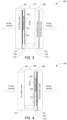
- FIGS. 3-4 show cross-sections of example double-pane window structures 300 and 400 that include Fabry-Perot etalons 326 and 426 in accordance with embodiments.
- the window structure 300 includes a first pane 302 and a second pane 304.
- a cavity 310 is formed between the first pane 302 and the second pane 304.
- the cavity 310 may be filled with a gas and/or sealed.
- the first pane 302 includes a first glass layer 312 and a third glass layer 316.
- the third glass layer 316 has first and second opposing surfaces. The second surface of the third glass layer 316 faces the cavity 310.
- a first low-E coating 322 is on the first surface of the third glass layer 316.
- a second low-E coating 324 is on the second surface of the third glass layer 316.
- the first low-E coating 322, the second low-E coating 324, and the third glass layer 316 combine to form the Fabry-Perot etalon 326, which is configured as a bandpass filter.
- the bandpass filter has a designated frequency passband that includes at least one microwave frequency (e.g., a range of microwave frequencies).
- Example implementations of a Fabry-Perot etalon, such as the Fabry-Perot etalon 326, and their properties are discussed in further detail below.
- the Fabry-Perot etalon 326 and the first glass layer 312 are attached using an adhesive 330. Accordingly, the first glass layer 312 is adhered to the first thermal emissivity coating 322.
- the second pane 304 includes a second glass layer 314 and a fourth glass layer 318, which are attached using an adhesive 320.
- Each of the adhesives 320 and 330 may be polyvinyl butyral, for example.
- a low-E coating may be placed on a surface of the second glass layer 314 that faces the cavity 310, though the scope of the example embodiments is not limited in this respect.
- the first pane 302 is shown in FIG. 3 to face an exterior of an object on which the window structure 300 is to be installed, and the second pane 304 is shown to face an interior of the object, for illustrative, non-limiting purposes. Accordingly, the first glass layer 312 may be said to face the exterior of the object. The second glass layer 314 and/or the fourth glass layer 318 may be said to face the interior of the object.
- the window structure 300 is formed by attaching a layer of EXG TM glass, which has standard low E-coatings deposited on respective sides of the glass, to an outer pane of a conventional double-pane window.
- the thickness of the EXG TM glass together with specific reflectivity values of the low-E coatings on the respective sides of the glass are designed to create the Fabri-Perot cavity 326 to form the pass band filter.
- the window structure 400 includes a first pane 402 and a second pane 404.
- a cavity 408 is formed between the first pane 402 and the second pane 404.
- the cavity 408 may be filled with a gas and/or sealed.
- the first pane 402 includes a first glass layer 412.
- the second pane 404 includes a second glass layer 414 and a third glass layer 416.
- the third glass layer 416 has first and second opposing surfaces. The first surface of the third glass layer 416 faces the cavity 408.
- a first low-E coating 422 is on the first surface of the third glass layer 416.
- a second low-E coating 424 is on the second surface of the third glass layer 416.
- the first low-E coating 422, the second low-E coating 424, and the third glass layer 416 combine to form the Fabry-Perot etalon 426, which is configured as a bandpass filter.
- the bandpass filter has a designated frequency passband that includes at least one microwave frequency (e.g., a range of microwave frequencies).
- Example implementations of a Fabry-Perot etalon, such as the Fabry-Perot etalon 426, and their properties are discussed in further detail below.
- the Fabry-Perot etalon 426 and the second glass layer 414 are attached using an adhesive 440. Accordingly, the second glass layer 414 is adhered to the second thermal emissivity coating 424.
- the adhesive 440 may be polyvinyl butyral, for example.
- a low-E coating may be placed on a surface of the first glass layer 412 that faces the cavity 408, though the scope of the example embodiments is not limited in this respect.
- the first pane 402 is shown in FIG. 4 to face an exterior of an object on which the window structure 400 is to be installed, and the second pane 404 is shown to face an interior of the object, for illustrative, non-limiting purposes. Accordingly, the first glass layer 412 may be said to face the exterior of the object. The second glass layer 414 may be said to face the interior of the object.
- the window structure 400 is formed by attaching a layer of EXG TM glass, which has standard low E-coatings deposited on respective sides of the glass, to an inner pane of a conventional double-pane window.
- the first low-E coating 222, 322, 422 shown in respective FIGS. 2-4 may have a first reflectivity with regard to infrared wavelengths.
- the second low-E coating 224, 324, 424 shown in respective FIGS. 2-4 may have a second reflectivity with regard to infrared wavelengths.
- the first and second low-E coatings 222 and 224, 322 and 324, 422 and 424 may be selected such that an average of the first reflectivity and the second reflectivity is at least a threshold percentage.
- the threshold percentage may be 85%, 90%, 95%, or other suitable percentage.
- the third glass layer 206, 306, 406 shown in respective FIGS. 2-4 may be fabricated using a fusion process, though the example embodiments are not limited in this respect. Relatively low thickness variation and relatively high flatness may be inherent characteristics of the fusion process. Accordingly, utilizing the fusion process may obviate a need to grind and polish the glass, which are customary steps in conventional glass fabrication processes.
- the designated frequency passband of any of the bandpass filters formed by the Fabry-Perot etalons 226, 326, and 426 mentioned above with reference to FIGS. 2-4 may include at least one frequency in a range of frequencies from 6 GHz to 80 GHz.
- the designated frequency passband may include at least one frequency in a range of frequencies from 20 GHz to 80 GHz, from 28 GHz to 80 GHz, or from 28 GHz to 60 GHz.
- the designated frequency passband may include 28 GHz, 37 GHz, 39 GHz, and/or 60 GHz.
- the designated frequency passband includes a range of frequencies from 28 GHz to 60 GHz.
- the designated frequency passband includes a range of frequencies from 6 GHz to 80 GHz.
- at least one of the Fabry-Perot etalons 226, 326, or 426 is configured to enable a signal that has a frequency in the range from 6 GHz to 80 GHz to have an attenuation, which results from the signal traveling at least 100 meters and passing through the respective window structure 200, 300, or 400, of less than or equal to 70dB.
- the thickness of the third glass layers 206, 306, and 406 in the respective Fabry-Perot etalons 226, 326, and 426 may be chosen based on which design criteria are most important for a given use case. For example, having a relatively thicker third glass layer 206, 306, 406 (e.g., in a range from 0.5 mm to 3.0 mm, or from 0.5 mm to 2.5 mm) may result in the Fabry-Perot etalon 226, 326, 426 having greater transmissivity (e.g., ⁇ 90%), though the Fabry-Perot etalon 226, 326, 426 may be more susceptible to incidence angle variations and have a narrower passband.
- the third glass layer 206, 306, 406 may be at least nine times or ten times more transmissive than soda-lime glass with regard to at least one frequency in the passband (e.g., at least one of 28 GHz, 37 GHz, 39 GHz, or 60 GHz). Accordingly, a relatively thicker third glass layer 206, 306, 406 may be more suitable for line-of-sight applications in which the angle of incidence of the targeted waveforms is near normal to the first and/or second surface(s) of the third glass layer 206, 306, 406 (e.g., less than a threshold angle of 10 degrees or 20 degrees with reference to normal). A relatively thicker third glass layer 206, 306, 406 may be more suitable for applications that require relatively greater transmissivity or that pertain to a relatively narrow band of frequencies.
- a relatively thicker third glass layer 206, 306, 406 may be more suitable for applications that require relatively greater transmissivity or that pertain to a relatively narrow band of frequencies.
- the Fabry-Perot etalon 206, 306, 406 may be configured such that a product of (a) a square of a permeability of the third glass layer 206, 306, 406 at a designated frequency in the passband and (b) a thickness of the third glass layer 206, 306, 406 equals approximately one-half of a wavelength that corresponds to a central frequency of the bandpass filter (or an integer multiple thereof).
- the third glass layer 206, 306, 406 has a thickness equal to an integer multiple of approximately 1.2 mm (e.g., for a target frequency of 60 GHz), approximately 1.7 mm (e.g., for a target frequency of 39 GHz), approximately 1.8 mm (e.g., for a target frequency of 37 GHz), or approximately 2.5 mm (e.g., for a target frequency of 28 GHz).
- having a relatively thinner third glass layer 206, 306, 406 may result in the Fabry-Perot etalon 226, 326, 426 being less affected by incidence angle and having a wider passband, though the Fabry-Perot etalon 226, 326, 426 may have less transmissivity (e.g., ⁇ 10%).
- the Fabry-Perot etalon 226, 326, 426 may be unaffected by (e.g., agnostic to) the angle of incidence for frequencies in the passband of the bandpass filter. Accordingly, a relatively thinner third glass layer 206, 306, 406 may be more suitable for applications in which the angle of incidence of the targeted waveforms varies substantially or in which the targeted frequencies cover a substantial portion (e.g., all) of the 5G frequency range (e.g., 28 GHz - 60 GHz or broader).
- the 5G frequency range e.g., 28 GHz - 60 GHz or broader.
- the third glass layer 206, 306, 406 may be fabricated to have a thickness variation that is less than a threshold variation.
- the thickness of the third glass layer 206, 306, 406 may vary no more than 20 ⁇ m or no more than 10 ⁇ m.
- the variation of a central frequency of the bandpass filter may be controlled.
- the third glass layer 206, 306, 406 may be configured to cause the central frequency of the bandpass filter to vary less than 1.0% or less than 0.5%.
- each of the window structures 200, 300, and 400 shown in FIGS. 2-4 may not include one or more of the components shown therein.
- each of the window structures 200, 300, and 400 may include components in addition to or in lieu of the components shown therein.
- any of the window structures 200, 300, and 400 may include one or more additional glass layers, low-E coatings, cavities, gases filling the cavities, adhesives, and so on.
- Embodiments in which the third glass layer 206, 306, 406 is relatively thick will be discussed first, followed by embodiments in which the third glass layer 206, 306, 406 is relatively thin.
- FIG. 5 is a cross-section of an example Fabry-Perot etalon 500 with normal angle of incidence of a microwave signal 528 in accordance with an embodiment.
- the Fabry-Perot etalon 500 includes a glass layer 516 having a thickness, d.
- First and second low emissivity coatings 522 and 524 are formed on opposing faces of the glass layer 516.
- the first and second low emissivity coatings 522 and 524 have respective reflectivities, R1 and R2.
- T( ⁇ ) represents the transmission of electromagnetic waves (e.g., microwave signal 528) through the Fabry-Perot etalon 500.
- ⁇ is the attenuation coefficient
- b. ⁇ 2 ⁇ ⁇ . n . tan ⁇
- tan( ⁇ ) is the dielectric loss tangent of the glass layer 516
- c. ⁇ 2 2 ⁇ ⁇ c nd cos ⁇ where f is the microwave frequency
- R1 and R2 are reflectivity coefficients (0-100%) of the respective first and second low emissivity coatings 522 and 524.
- the transmission T( ⁇ ) for the Fabry-Perot etalon 526 reaches a maximum when nd in Equation 3 reaches ⁇ /2, where ⁇ is wavelength.
- FIG. 6 is a plot 600 of an example transmission spectrum of a Fabry-Perot etalon 526 shown in FIG. 5 as a function of frequency in accordance with an embodiment.
- the resonant frequency is shown to be 28 GHz for non-limiting illustrative purposes. It will be recognzied that the Fabry-Perot etalon 526 may be configured to have any suitable resonant frequency.
- This relatively low reflectivity value results in a rather broad passband filter function such that the width at the 3dB level (i.e., transmission of 0.5 in the plot) is approximately 1 GHz, as depicted in FIG. 6 .
- the Fabry-Perot etalon may designed to have the width at the 3dB level be greater than or equal to approximately 1 GHz (e.g., greater than or equal to 0.8 GHz). Designing the Fabry-Perot etalon 526 to have a passband filter function with a width of approximately 1 GHz at the 3dB level is consistent with the expected 0.8 GHz frequency spectrum allocated for 5Guse.
- the glass layer 516 of the Fabry-Perot etalon 526 is EXG TM glass.
- the thickness variation ⁇ d of EXG TM glass is less than the thickness variation of SLG, which results in the EXG TM glass exhibiting a lower central frequency variation ⁇ f 0 than the SLG.
- the thickness variations and frequency variations shown in FIG. 7 are not to scale and are provided merely for illustrative purposes.
- the thickness variation ⁇ d of EXG TM glass is approximately 10 ⁇ m, and the thickness variation of SLG is at least ten times higher (i.e., at least 100 ⁇ m). Accordingly, the cential frequency variation ⁇ f of EXG TM glass is on the order of 0.4%; whereas, the resonance position (i.e., central frequency) of SLG can shift by as much as 3.55%. The shift in the central frequency of the passband filter will result in increased loss of the microwave signal. It should also be noted that SLG requires a greater thickness than EXG TM glass, which adds weight.
- a single silver-based coating provides a 1.5 dB improvement in shielding effectiveness for EXG TM glass versus SLG.
- a double silver-based coating provides a 2dB improvement when using EXG TM glass versus SLG.
- a triple silver-based coating provides more than 3dB improvement for EXG TM glass versus SLG.
- the window industry tends to provide even more performant low-E coatings (i.e., higher reflectivity) to improve the thermal performance of the window. By using EXG TM glass, low dielectric loss tangent will improve the microwave signal against standard SLG by 3dB.
- FIG. 10 is a cross-section of an example Fabry-Perot etalon 1000 for which an angle of incidence of a microwave signal 1028 is not normal in accordance with an embodiment.
- the Fabry-Perot etalon 1000 includes a glass layer 1016 and low-E coatings 1022 and 1024 on opposing surfaces of the glass layer 1016.
- FIG. 10 is provided to illustrate reflection and transmission of the microwave signal 1028, which is incident on the Fabry-Perot etalon 1000 at an angle, i.
- FIG. 11 is an example plot 1100 showing transmission of EXG TM glass having a thickness of 2.33 mm (optimized for 28 GHz) at a variety of incidence angles in accordance with an embodiment.
- an angle of incidence other than zero has negatively affects transmission through the Fabry-Perot etalon.
- reflectivity of the low-E coatings on respective faces of the EXG TM glass layer were set at 90%, and the losses due to the relatively low thickness d of the EXG TM glass layer were neglected.
- the pass band transfer function of the Fabry-Perot etalon shifts at the angles of incidence other than zero, such that a relatively greater angle of incidence results in a relatively greater shift.
- BB radiation will see two reflective surfaces with each having a reflectivity of 90% (i.e., letting through only 1% of BB 10 ⁇ m radiation), and the low-E coatings will contribute to enhancing energy efficiency of the window.
- Double-pane design may have several implementaions.
- the EXG TM glass layer coated with low-E coatings with the same thickness d as in the tripple pane design can be attached to either the cavity-facing surface of the first pane or the cavity-facing surface of the second pane, as depicted in FIGS. 3-4 .
- the passband function is similar to the pasband function of the triple-pane design, an example of which is shown in FIG. 2
- the glass layer of the Fabry-Perot etalon is relatively thin (e.g., d ⁇ 1 mm).
- the glass layer may have a thickness of approximately 0.7 mm.
- the thicknes of the glass layer may be as thin as possible while maintaining mechanical integrity, rather than choosing a very specific thickness of the glass layer to tune the Fabri-Perot etalon at the maximum of the transmittance.
- the thin glass layer is attached (e.g., glazed) to one of the glass layers that have larger glass thickness.
- the thickness d in Equation 10 is less than or equal to 220 ⁇ m.
- FIG. 12 is an example plot 1200 showing transmission as a function of frequency for an EXG TM glass layer having a thickness of 50 ⁇ m in accordance with an embodiment.
- the plot 1200 includes multiple curves corresponding to incidence angles of 0°, 10°, 20°, 30°.
- FIG. 13 is an example plot 1300 showing transmission as a function of frequency for a Fabry-Perot etalon that includes an EXG TM glass layer having a thickness of 50 ⁇ m with low emissivity coatings on opposing surfaces of the EXG TM glass layer in accordance with an embodiment.
- each of the low-E coatings has a reflection of 90% for illustrative purposes.
- the plot 1300 includes multiple curves corresponding to incidence angles of 0°, 10°, 20°, 30°.
- Embodiments in which the Fabry-Perot etalon has a relatively thin glass layer have a variety of advantages as compared to embodiments in which the Fabry-Perot etalon has a relatively thick glass layer.
- the transmission function for the embodiments having a relatively thin glass layer becomes very independent of frequency. Equation 9 in the assimptotical limit of d ⁇ 0 shows 1 1 + ⁇ cos 2 ⁇ 2 behavior with frequency rather than sharp "passband" function. ⁇ is a relatively small parameter in this calculation.
- FIG. 14 is an example plot showing transmission of an EXG TM glass layer at a target frequency of 28 GHz as a function of angle of incidence for a range of glass thicknesses in accordance with an embodiment.
- FIG. 14 shows a first curve 1402 corresponding to a glass thickness of 1/2 of the wavelength of the electromagnetic wave, a second curve 1404 corresponding to a glass thickness of 100 ⁇ m, and a third curve 1406 corresponding to a glass thickness of 50 ⁇ m.
- the transmission is much less affected by the angle of incidence for the relatively thin glass layers (i.e., curves 1404 and 1406) as compared to the relatively thicker glass layer (i.e., curve 1402).
- Fabry-Perot etalon structures described herein with reference to a double-pane design may be incorporated into a triple-panel design by adhering the Fabry-Perot etalon to a cavity-facing surface of any of the panes in the triple-pane design.
- FIGS. 15 and 16 are provided as example plots 1500 and 1600 showing filter response of a Fabry-Perot etalon that includes a relatively thin glass layer and low-E coatings having a reflectance of 90% for an angle of incidence of 0° at respective target frequencies of 28 GHz and 60 GHz in accordance with embodiments.
- curves 1502 and 1504 represent the shielding effectiveness of SLG and EXG TM glass, respectively, over a range of glass thicknesses from 10 to 200 ⁇ m.
- Curves 1512 and 1514 represent the transmissivity of SLG and EXG TM glass, respectively, over the range of thicknesses.
- curves 1602 and 1604 represent the shielding effectiveness SE(dB) of SLG and EXG TM glass, respectively, over the range of thicknesses.
- Curves 1612 and 1614 represent the transmissivity T(%) of SLG and EXG TM glass, respectively, over the range of thicknesses.
- Equation 1 shows that transmission T( ⁇ ) tends towards 100% (i.e., SE(dB) towards 0dB) when thickness d tends towards 0 mm.
- the maximum signal dampening may be 10 dB for 60 Ghz and 4-5 dB for 28 Ghz.
- a frequency agnostic window e.g., from 20 GHz to 60 GHz
- the relatively low thickness of the glass layer may cause the Fabry-Perot etalon to be incidence angle agnostic, as well.
- the glass layer may be laminated onto a thicker piece of glass in accordance with the dual-pane embodiments described above with regard to FIGS. 3 -E.
- FIG. 17 depicts a flowchart 1700 of an example method for using a window structure having first, second, and third glass layers in accordance with an embodiment.
- Flowchart 1700 may be performed by any of window structures 200, 300, and 400 shown in respective FIGS. 2-4 , for example.
- flowchart 1700 will be described with reference to the Fabry-Perot etalons 226, 326, 426, 500, or 1000 shown in respective FIGS. 2-5 and 10 . Further structural and operational embodiments will be apparent to persons skilled in the relevant art(s) based on the discussion regarding the flowchart 1700.
- step 1702 infrared radiation is received at a Fabry-Perot etalon, which is formed by the third glass layer and further by first and second low-E coatings on respective first and second opposing surfaces of the third glass layer, via the first glass layer.
- Fabry-Perot etalon 226, 326, 426, 500, or 1000 receives the infrared radiation.
- receiving the infrared radiation at step 1702 includes receiving the infrared radiation at the Fabry-Perot etalon via the first glass layer and a sealed gas-filled cavity that is formed between the first glass layer and the third glass layer.
- the infrared radiation is attenuated using the first and second low-E coatings.
- first and second low-E coatings 222 and 224, 322 and 324, 422 and 424, 522 and 524, or 1022 and 1024 attenuate the infrared radiation.
- a signal having a frequency in a range of frequencies from 6 gigahertz to 80 gigahertz is received at the Fabry-Perot etalon via the first glass layer.
- Fabry-Perot etalon 226, 326, 426, 500, or 1000 receives the signal having the frequency in the range of frequencies from 6 gigahertz to 80 gigahertz.
- the signal is passed through the bandpass filter and the third glass layer based at least in part on the bandpass filter having a designated frequency passband that includes the frequency.
- the bandpass filter that is formed by the Fabry-Perot etalon 226, 326, 426, 500, or 1000 and the third glass layer 216, 316, 416, 516, or 1016 pass the signal based at least in part on the bandpass filter having the designated frequency passband that includes the frequency.
- passing the signal through the bandpass filter at step 1708 includes passing the signal through the bandpass filter, a sealed gas-filled cavity that is formed between the second glass layer and the third glass layer, and the third glass layer based at least in part on the designated frequency passband of the bandpass filter including the frequency.
- one or more steps 1702, 1704, 1706, and/or 1708 of flowchart 1700 may not be performed. Moreover, steps in addition to or in lieu of steps 1702, 1704, 1706, and/or 1708 may be performed.
- the example embodiments may improve the transmission coefficient for a window structure that uses low-E coatings that otherwise (i.e., without a Fabry-Perot etalon described herein) would exhibit microwave loss of 20-30 dB.
- low-E coatings having reflectivities of 90% i.e., transmission of 10%
- the low-E coatings may have any suitable reflectivities. Two low-E coatings having reflectivities of 90% and being separated by an arbitrary distance would result in a combined transmission of 1% (i.e., signal will suffer from 20 dB of loss).
- a variety of example window structures that include a Fabry-Perot etalon (e.g., Fabry-Perot cavity filter) have been presented to increase transmission in the targeted frequency bands.
- the greatest transmission may be achieved by using a half-wavelength Fabry-Perot cavity formed by EXG TM glass having a thickness of 2.33 mm, though such a half-wavelength Fabry-Perot cavity may have a finite bandwidth and sharp angle dependence, as depicted by curve 1402 in FIG. 14 .
- the cavity may be formed by a relatively thin glass (e.g., an EXG TM glass layer having a thickness of 50 ⁇ m or 100 ⁇ m).
- EXG TM glass having a thickness of 50 ⁇ m exhibits less than 5 dB of loss at 28 GHz.
- EXG TM glass having a thickness of 100 ⁇ m exhibits less than 9 dB of loss at 28 GHz.
- a loss reduction midway between these two values i.e., 13 dB
- 13 dB is selected merely for illustrative purposes and is not intended to be limiting. Any suitable loss reduction may be selected.
- FIG. 18 is a diagram of an example microwave link 1800 in accordance with an embodiment.
- the microwave link 1800 includes a transmitter 1842, a receiver 1844, and a window 1846.
- the transmitter 1842 and the receiver 1844 are separated by a distance D.
- Equation 11 stipulates that receiver power (S RX ) is equal to transmitter power (P TX ) minis all pass losses (PL FS , PL W ) plus antenna gains (A TX , A RX ).
- PL FS represents free space propagation loss (i.e., the loss through free space between the transmitter 1842 and the window 1846).
- PL W represents window loss (i.e., the loss through the window 1846).
- a TX represents the gain of the transmitter antenna.
- a RX represents the gain of the receiver antenna.
- FIG. 19 is an example plot 1900 of free space propagation loss (PL FS ) with respect to distance for a variety of frequencies in accordance with an embodiment.
- the propagation loss PL FS increases by 6 dB for every doubling of the distance. Since window loss and free space propagation loss are subtracted from the transmitter power in Equation 11, reduction in window loss by 13 dB would enable the link to be at least 4 times longer. In other words, such reduction in window loss would enable the distance D between the transmitter 1842 and the receiver 1844 to be quadrupled because the 13 dB reduction in window loss can accommodate the 12 dB increase in free space propagation loss that would result from the distance D being quadrupled.
- the example embodiments described herein could theortically enable increasing the propagation distance by 4 times.
- the increase in distance will inevitably coincide with introduction of other losses (e.g., foliage and absoprtion due to water (e.g., rain)), which may reduce an actual acheiveable increase in distance.
- SNR signal-to-noise ratio
- Equation 13 shows that having higher Psig at the receiver 1844 enables higher SNR, which in turn allows higher data rate B.
- Equation 12 The increase in the bit rate cannot be determined using Equation 12 because the increase depends on the starting SNR (i.e., with the window not having enhanced microwave transparency).
- Equation 14 shows a maximum acheivable spectral efficiency in real hardware, very high spectral efficiency may not be realized due to complexity of the modulaion format that is needed for its realization.
- replacing a conventional window with a microwave-transparent window in accordance with the techniques described herein may (a) enable the distance from the 5G transmitter to the receiver to be increased by 4 times, assuming that there are no other sources of loss except free space propagation loss and window loss), and (b) increase data rate in the communication channel by up to 66%.
- FIG. 20 is an example table of some common modulation formats that are used in 5G links, along with corresponding maximum spectral efficiencies and minimum required signal-to-noise ratios (SNR) at the receiver, in accordance with an embodiment.
- FIG. 21 is an example plot 2100 of receiver power (i.e., signal power at the receiver) with respect to distance from a transmitting antenna for three example windows in accordance with an embodiment.
- the signal that is incident at the receiver has a frequency of 60 GHz.
- the receiver includes an antenna having an antenna gain of 30 dBi and an effective isotropic radiated power (EIRP) of 40 dBm for purposes of illustration.
- EIRP effective isotropic radiated power
- the signal needs to have a power greater than or equal to a sensitivity threshold of -60 dB in order to be detected by the antenna.
- the sensitivity threshold is represented by line 2102.
- Curve 2104 represents the power of the signal in free space (e.g., without passing through a window) at various distances from the transmitting antenna. As shown in FIG. 21 , the signal can travel approximately 375 m in free space before reaching the sensitivity threshold.
- Curve 2106 represents the power of the signal as it passes through a first window (i.e., Window #1) having a first window loss of approximately -15 dB.
- the signal has approximately -60 dB of power after passing through the first window when the first window is approximately 125 m from the transmitting antenna. Accordingly, 125 m is the maximum distance that the first window can be from the transmitting antenna in order for the signal to be detected through the first window.
- Curve 2108 represents the power of the signal as it passes through a second window (i.e., Window #2) having a second window loss of approximately -20 dB.
- the signal has approximately -60 dB of power after passing through the second window when the second window is approximately 85 m from the transmitting antenna. Accordingly, 85 m is the maximum distance that the second window can be from the transmitting antenna in order for the signal to be detected through the second window.
- Curve 2110 represents the power of the signal as it passes through a low thermal emissivity (a.k.a. low-E) coated window having a third window loss of approximately -30 dB.
- the signal has approximately -60 dB of power after passing through the low-E coated window when the low-E coated window is approximately 50 m from the transmitting antenna. Accordingly, 50 m is the maximum distance that the low-E coated window can be from the transmitting antenna in order for the signal to be detected through the low-E coated window.
- a signal that has a frequency in the range from 6 GHz to 80 GHz may have an attenuation, which results from the signal traveling at least a threshold distance and passing through the window structure, of less than or equal to -70dB.
- the threshold distance may be 100 m, 125 m, or 150 m.
- a first example window structure comprises first, second, and third glass layers.
- the third glass layer is positioned between the first and second glass layers.
- First and second low thermal emissivity coatings are on respective first and second opposing surfaces of the third glass layer to form a Fabry-Perot etalon that is configured as a bandpass filter having a designated frequency passband that includes at least one frequency in a range of frequencies from 6 gigahertz to 80 gigahertz.
- the third glass layer is positioned between the first and second glass layers to form a first cavity between the first glass layer and the third glass layer and to form a second cavity between the second glass layer and the third glass layer.
- a distance between the first surface and the first glass layer is less than a distance between the second surface and the first glass layer.
- the first glass layer is adhered to the first low thermal emissivity coating.
- the third glass layer is positioned between the first and second glass layers to form a cavity between the second glass layer and the third glass layer.
- the first glass layer is configured to face an exterior of a building when the window structure is installed.
- the second glass layer is configured to face an interior of the building when the window structure is installed.
- a distance between the first surface and the first glass layer is less than a distance between the second surface and the first glass layer.
- the third glass layer is positioned between the first and second glass layers to form a cavity between the first glass layer and the third glass layer.
- the second glass layer is adhered to the second low thermal emissivity coating.
- the first glass layer is configured to face an exterior of a building when the window structure is installed.
- the second glass layer is configured to face an interior of the building when the window structure is installed.
- the third glass layer is at least nine times more transmissive than soda lime glass with regard to at least one of 28 gigahertz, 37 gigahertz, 39 gigahertz, or 60 gigahertz.
- the fourth aspect of the first example window structure may be implemented in combination with the first, second, and/or third aspect of the first example window structure, though the example embodiments are not limited in this respect.
- the fifth aspect of the first example window structure may be implemented in combination with the first, second, third, and/or fourth aspect of the first example window structure, though the example embodiments are not limited in this respect.
- the designated frequency passband of the bandpass filter includes at least one frequency in a range of frequencies from 28 gigahertz to 80 gigahertz.
- the sixth aspect of the first example window structure may be implemented in combination with the first, second, third, fourth, and/or fifth aspect of the first example window structure, though the example embodiments are not limited in this respect.
- the designated frequency passband of the bandpass filter includes at least one of 28 gigahertz, 37 gigahertz, 39 gigahertz, or 60 gigahertz.
- the seventh aspect of the first example window structure may be implemented in combination with the first, second, third, fourth, fifth, and/or sixth aspect of the first example window structure, though the example embodiments are not limited in this respect.
- the designated frequency passband of the bandpass filter includes a range of frequencies from 28 gigahertz to 60 gigahertz.
- the eighth aspect of the first example window structure may be implemented in combination with the first, second, third, fourth, fifth, sixth, and/or seventh aspect of the first example window structure, though the example embodiments are not limited in this respect.
- the designated frequency passband of the bandpass filter includes a range of frequencies from 6 gigahertz to 80 gigahertz.
- the ninth aspect of the first example window structure may be implemented in combination with the first, second, third, fourth, fifth, sixth, seventh, and/or eighth aspect of the first example window structure, though the example embodiments are not limited in this respect.
- the third glass layer has a maximum thickness variation of less than or equal to 20 micrometers.
- the tenth aspect of the first example window structure may be implemented in combination with the first, second, third, fourth, fifth, sixth, seventh, eighth, and/or ninth aspect of the first example window structure, though the example embodiments are not limited in this respect.
- the third glass layer has a maximum thickness variation of less than or equal to 10 micrometers.
- the eleventh aspect of the first example window structure may be implemented in combination with the first, second, third, fourth, fifth, sixth, seventh, eighth, ninth, and/or tenth aspect of the first example window structure, though the example embodiments are not limited in this respect.
- the third glass layer has a thickness in a range from 0.5 millimeters to 3.0 millimeters.
- the twelfth aspect of the first example window structure may be implemented in combination with the first, second, third, fourth, fifth, sixth, seventh, eighth, ninth, tenth, and/or eleventh aspect of the first example window structure, though the example embodiments are not limited in this respect.
- the third glass layer has a thickness equal to an integer multiple of approximately 1.2 millimeters, approximately 1.7 millimeters, approximately 1.8 millimeters, or approximately 2.5 millimeters.
- the thirteenth aspect of the first example window structure may be implemented in combination with the first, second, third, fourth, fifth, sixth, seventh, eighth, ninth, tenth, eleventh, and/or twelfth aspect of the first example window structure, though the example embodiments are not limited in this respect.
- the third glass layer has a thickness in a range from 10 micrometers to 500 micrometers.
- the fourteenth aspect of the first example window structure may be implemented in combination with the first, second, third, fourth, fifth, sixth, seventh, eighth, ninth, tenth, eleventh, twelfth, and/or thirteenth aspect of the first example window structure, though the example embodiments are not limited in this respect.
- a frequency response of the bandpass filter is unaffected by incidence angles of signals having frequencies in the designated frequency passband.
- the fifteenth aspect of the first example window structure may be implemented in combination with the first, second, third, fourth, fifth, sixth, seventh, eighth, ninth, tenth, eleventh, twelfth, thirteenth, and/or fourteenth aspect of the first example window structure, though the example embodiments are not limited in this respect.
- the third glass layer is configured to cause a central frequency of the bandpass filter to vary less than 1.0 percent.
- the sixteenth aspect of the first example window structure may be implemented in combination with the first, second, third, fourth, fifth, sixth, seventh, eighth, ninth, tenth, eleventh, twelfth, thirteenth, fourteenth, and/or fifteenth aspect of the first example window structure, though the example embodiments are not limited in this respect.
- the third glass layer is configured to cause a central frequency of the bandpass filter to vary less than 0.5 percent.
- the seventeenth aspect of the first example window structure may be implemented in combination with the first, second, third, fourth, fifth, sixth, seventh, eighth, ninth, tenth, eleventh, twelfth, thirteenth, fourteenth, fifteenth, and/or sixteenth aspect of the first example window structure, though the example embodiments are not limited in this respect.
- the third glass layer has a dielectric loss tangent of less than 0.01.
- the eighteenth aspect of the first example window structure may be implemented in combination with the first, second, third, fourth, fifth, sixth, seventh, eighth, ninth, tenth, eleventh, twelfth, thirteenth, fourteenth, fifteenth, sixteenth, and/or seventeenth aspect of the first example window structure, though the example embodiments are not limited in this respect.
- the third glass layer has a dielectric loss tangent of less than 0.006.
- the nineteenth aspect of the first example window structure may be implemented in combination with the first, second, third, fourth, fifth, sixth, seventh, eighth, ninth, tenth, eleventh, twelfth, thirteenth, fourteenth, fifteenth, sixteenth, seventeenth, and/or eighteenth aspect of the first example window structure, though the example embodiments are not limited in this respect.
- the window structure is capable of being fabricated using existing window processing techniques.
- the Fabry-Perot etalon is compatible with existing window structures.
- the twentieth aspect of the first example window structure may be implemented in combination with the first, second, third, fourth, fifth, sixth, seventh, eighth, ninth, tenth, eleventh, twelfth, thirteenth, fourteenth, fifteenth, sixteenth, seventeenth, eighteenth, and/or nineteenth aspect of the first example window structure, though the example embodiments are not limited in this respect.
- the bandpass filter has a 3dB bandwidth greater than or equal to approximately one gigahertz.
- the twenty-first aspect of the first example window structure may be implemented in combination with the first, second, third, fourth, fifth, sixth, seventh, eighth, ninth, tenth, eleventh, twelfth, thirteenth, fourteenth, fifteenth, sixteenth, seventeenth, eighteenth, nineteenth, and/or twentieth aspect of the first example window structure, though the example embodiments are not limited in this respect.
- the first low thermal emissivity coating and the second low thermal emissivity coating have respective first and second reflectivities with regard to infrared wavelengths.
- an average of the first reflectivity and the second reflectivity is at least 85%.
- the twenty-second aspect of the first example window structure may be implemented in combination with the first, second, third, fourth, fifth, sixth, seventh, eighth, ninth, tenth, eleventh, twelfth, thirteenth, fourteenth, fifteenth, sixteenth, seventeenth, eighteenth, nineteenth, twentieth, and/or twenty-first aspect of the first example window structure, though the example embodiments are not limited in this respect.
- the first low thermal emissivity coating and the second low thermal emissivity coating have respective first and second reflectivities with regard to infrared wavelengths.
- an average of the first reflectivity and the second reflectivity is at least 90%.
- the twenty-third aspect of the first example window structure may be implemented in combination with the first, second, third, fourth, fifth, sixth, seventh, eighth, ninth, tenth, eleventh, twelfth, thirteenth, fourteenth, fifteenth, sixteenth, seventeenth, eighteenth, nineteenth, twentieth, twenty-first, and/or twenty-second aspect of the first example window structure, though the example embodiments are not limited in this respect.
- the first low thermal emissivity coating and the second low thermal emissivity coating have respective first and second reflectivities with regard to infrared wavelengths.
- an average of the first reflectivity and the second reflectivity is at least 95%.
- the twenty-fourth aspect of the first example window structure may be implemented in combination with the first, second, third, fourth, fifth, sixth, seventh, eighth, ninth, tenth, eleventh, twelfth, thirteenth, fourteenth, fifteenth, sixteenth, seventeenth, eighteenth, nineteenth, twentieth, twenty-first, twenty-second, and/or twenty-third aspect of the first example window structure, though the example embodiments are not limited in this respect.
- the Fabry-Perot etalon is configured to enable a signal that has a frequency in the range from 6 gigahertz to 80 gigahertz to have an attenuation, which results from the signal traveling at least 100 meters and passing through the window structure, of less than or equal to 70dB.
- the twenty-fifth aspect of the first example window structure may be implemented in combination with the first, second, third, fourth, fifth, sixth, seventh, eighth, ninth, tenth, eleventh, twelfth, thirteenth, fourteenth, fifteenth, sixteenth, seventeenth, eighteenth, nineteenth, twentieth, twenty-first, twenty-second, twenty-third, and/or twenty-fourth aspect of the first example window structure, though the example embodiments are not limited in this respect.
- a second example window structure comprises first, second, and third glass layers.
- Each of the first and second glass layers comprises a soda-lime glass.
- the third glass layer has a first face and a second face, a thickness of less than 2.5 millimeters, a thickness variation of less than 10 micrometers, and a dielectric loss tangent of less than 0.01.
- the third glass layer is positioned between the first and second glass layers to form a first cavity between the first glass layer and the third glass layer.
- the second example window structure further comprises first coating on the first face of the third glass layer and a second coating on the second face of the third glass layer.
- the first and second coatings comprise respective reflective low-emissive coatings.
- the third glass layer in combination with the first and second coatings form a Fabry-Perot etalon that is configured as a bandpass filter having a designated frequency passband that includes at least one frequency in a range of frequencies from 20 gigahertz to 80 gigahertz.
- the third glass layer is positioned between the first and second glass layers further to form a second cavity between the second glass layer and the third glass layer.
- the third glass layer is configured to be at least ten times more transmissive than soda lime glass with regard to at least one of 28 gigahertz, 37 gigahertz, 39 gigahertz, or 60 gigahertz.
- the second aspect of the second example window structure may be implemented in combination with the first aspect of the second example window structure, though the example embodiments are not limited in this respect.
- a product of (a) a square of a permeability of the third glass layer at a designated frequency that is included among the at least one frequency and (b) the thickness of the third glass layer equals approximately one-half of a wavelength that corresponds to a central frequency of the bandpass filter.
- the third aspect of the second example window structure may be implemented in combination with the first and/or second aspect of the second example window structure, though the example embodiments are not limited in this respect.
- the designated frequency passband of the bandpass filter includes a range of frequencies from 28 gigahertz to 60 gigahertz.
- the fourth aspect of the second example window structure may be implemented in combination with the first, second, and/or third aspect of the second example window structure, though the example embodiments are not limited in this respect.
- the bandpass filter has a 3dB bandwidth greater than or equal to 0.8 gigahertz.
- the fifth aspect of the second example window structure may be implemented in combination with the first, second, third, and/or fourth aspect of the second example window structure, though the example embodiments are not limited in this respect.
- the low-emissive coatings in the respective first and second coatings have respective first and second reflectivities with regard to infrared wavelengths.
- an average of the first reflectivity and the second reflectivity is at least 90%.
- the sixth aspect of the second example window structure may be implemented in combination with the first, second, third, fourth, and/or fifth aspect of the second example window structure, though the example embodiments are not limited in this respect.
- infrared radiation is received at a Fabry-Perot etalon, which is formed by the third glass layer and further by first and second low thermal emissivity coatings on respective first and second opposing surfaces of the third glass layer, via the first glass layer.
- the infrared radiation is attenuated using the first and second low thermal emissivity coatings.
- a signal having a frequency in a range of frequencies from 6 gigahertz to 80 gigahertz is received at the Fabry-Perot etalon via the first glass layer.
- the signal is passed through the bandpass filter and the third glass layer based at least in part on the bandpass filter having a designated frequency passband that includes the frequency.
- receiving the infrared radiation comprises receiving the infrared radiation at the Fabry-Perot etalon via the first glass layer and a sealed gas-filled cavity that is formed between the first glass layer and the third glass layer.
- passing the signal through the bandpass filter comprises passing the signal through the bandpass filter, a sealed gas-filled cavity that is formed between the second glass layer and the third glass layer, and the third glass layer based at least in part on the designated frequency passband of the bandpass filter including the frequency.
- the second aspect of the example method may be implemented in combination with the first aspect of the example method, though the example embodiments are not limited in this respect.
Landscapes
- Chemical & Material Sciences (AREA)
- Engineering & Computer Science (AREA)
- Physics & Mathematics (AREA)
- Life Sciences & Earth Sciences (AREA)
- Chemical Kinetics & Catalysis (AREA)
- General Chemical & Material Sciences (AREA)
- Geochemistry & Mineralogy (AREA)
- Materials Engineering (AREA)
- Organic Chemistry (AREA)
- Optics & Photonics (AREA)
- General Physics & Mathematics (AREA)
- Civil Engineering (AREA)
- Structural Engineering (AREA)
- Optical Filters (AREA)
- Joining Of Glass To Other Materials (AREA)
Applications Claiming Priority (3)
| Application Number | Priority Date | Filing Date | Title |
|---|---|---|---|
| US201862649808P | 2018-03-29 | 2018-03-29 | |
| EP19722262.3A EP3774685B1 (fr) | 2018-03-29 | 2019-03-28 | Fenêtre transparente aux micro-ondes à efficacité énergétique compatible avec la présente conception |
| PCT/US2019/024666 WO2019191485A1 (fr) | 2018-03-29 | 2019-03-28 | Fenêtre transparente aux micro-ondes à efficacité énergétique compatible avec la présente conception |
Related Parent Applications (2)
| Application Number | Title | Priority Date | Filing Date |
|---|---|---|---|
| EP19722262.3A Division EP3774685B1 (fr) | 2018-03-29 | 2019-03-28 | Fenêtre transparente aux micro-ondes à efficacité énergétique compatible avec la présente conception |
| EP19722262.3A Division-Into EP3774685B1 (fr) | 2018-03-29 | 2019-03-28 | Fenêtre transparente aux micro-ondes à efficacité énergétique compatible avec la présente conception |
Publications (2)
| Publication Number | Publication Date |
|---|---|
| EP4242410A2 true EP4242410A2 (fr) | 2023-09-13 |
| EP4242410A3 EP4242410A3 (fr) | 2023-10-25 |
Family
ID=66429489
Family Applications (2)
| Application Number | Title | Priority Date | Filing Date |
|---|---|---|---|
| EP23188301.8A Pending EP4242410A3 (fr) | 2018-03-29 | 2019-03-28 | Fenêtre transparente aux micro-ondes à efficacité énergétique compatible avec la présente conception |
| EP19722262.3A Active EP3774685B1 (fr) | 2018-03-29 | 2019-03-28 | Fenêtre transparente aux micro-ondes à efficacité énergétique compatible avec la présente conception |
Family Applications After (1)
| Application Number | Title | Priority Date | Filing Date |
|---|---|---|---|
| EP19722262.3A Active EP3774685B1 (fr) | 2018-03-29 | 2019-03-28 | Fenêtre transparente aux micro-ondes à efficacité énergétique compatible avec la présente conception |
Country Status (7)
| Country | Link |
|---|---|
| US (1) | US20210032926A1 (fr) |
| EP (2) | EP4242410A3 (fr) |
| KR (1) | KR20200138768A (fr) |
| CN (2) | CN112004784B (fr) |
| CA (1) | CA3095306A1 (fr) |
| TW (1) | TW201942462A (fr) |
| WO (1) | WO2019191485A1 (fr) |
Families Citing this family (1)
| Publication number | Priority date | Publication date | Assignee | Title |
|---|---|---|---|---|
| CA3198811A1 (fr) * | 2020-10-16 | 2022-04-21 | Agc Glass Europe | Procede de determination d'un pourcentage de surface de verre a traiter et invention mobile associee |
Family Cites Families (10)
| Publication number | Priority date | Publication date | Assignee | Title |
|---|---|---|---|---|
| JP2004231471A (ja) * | 2003-01-30 | 2004-08-19 | National Institute Of Advanced Industrial & Technology | 結晶化ガラス |
| US20040234198A1 (en) * | 2003-03-21 | 2004-11-25 | Aegis Semiconductor, Inc. | Tunable and switchable multiple-cavity thin film optical filters |
| US20070242358A1 (en) * | 2006-04-18 | 2007-10-18 | Xerox Corporation | Fabry-perot tunable filter |
| WO2013052927A2 (fr) * | 2011-10-07 | 2013-04-11 | Svaya Nanotechnologies, Inc. | Film de contrôle solaire à large bande |
| US9556066B2 (en) * | 2011-12-13 | 2017-01-31 | Guardian Industries Corp. | Insulating glass units with low-E and antireflective coatings, and/or methods of making the same |
| US9499438B2 (en) * | 2013-02-28 | 2016-11-22 | Guardian Industries Corp. | Window for attenuating RF and IR electromagnetic signals |
| PL2964585T3 (pl) * | 2013-03-07 | 2020-05-18 | Saint-Gobain Glass France | Szyba powlekana z obszarami częściowo niepowlekanymi |
| US8927069B1 (en) * | 2013-10-02 | 2015-01-06 | Eritek, Inc. | Method and apparatus for improving radio frequency signal transmission through low-emissivity coated glass |
| EP3440778B1 (fr) * | 2016-04-04 | 2022-03-23 | NxGen Partners IP, LLC | Re-génération et re-transmission d'ondes millimétriques destinées à pénétrer dans un bâtiment |
| DK3309343T3 (da) * | 2016-10-11 | 2019-08-05 | Lammin Ikkuna Oy | Rudeindretning |
-
2019
- 2019-03-28 CN CN201980027489.2A patent/CN112004784B/zh active Active
- 2019-03-28 EP EP23188301.8A patent/EP4242410A3/fr active Pending
- 2019-03-28 CA CA3095306A patent/CA3095306A1/fr active Pending
- 2019-03-28 EP EP19722262.3A patent/EP3774685B1/fr active Active
- 2019-03-28 CN CN202310509423.5A patent/CN116591585A/zh active Pending
- 2019-03-28 KR KR1020207030698A patent/KR20200138768A/ko not_active Application Discontinuation
- 2019-03-28 US US17/042,651 patent/US20210032926A1/en not_active Abandoned
- 2019-03-28 WO PCT/US2019/024666 patent/WO2019191485A1/fr active Application Filing
- 2019-03-29 TW TW108111138A patent/TW201942462A/zh unknown
Also Published As
| Publication number | Publication date |
|---|---|
| EP4242410A3 (fr) | 2023-10-25 |
| WO2019191485A1 (fr) | 2019-10-03 |
| CA3095306A1 (fr) | 2019-10-03 |
| CN112004784B (zh) | 2023-05-26 |
| EP3774685A1 (fr) | 2021-02-17 |
| US20210032926A1 (en) | 2021-02-04 |
| KR20200138768A (ko) | 2020-12-10 |
| TW201942462A (zh) | 2019-11-01 |
| CN116591585A (zh) | 2023-08-15 |
| EP3774685B1 (fr) | 2023-09-06 |
| CN112004784A (zh) | 2020-11-27 |
Similar Documents
| Publication | Publication Date | Title |
|---|---|---|
| US5488371A (en) | Radio frequency absorbing windows | |
| EP3309343B1 (fr) | Agencement de vitrage | |
| EP3399595B1 (fr) | Fenêtre de transparence de fréquence radio multibande dans un film conducteur | |
| EP3774685B1 (fr) | Fenêtre transparente aux micro-ondes à efficacité énergétique compatible avec la présente conception | |
| WO2019173369A1 (fr) | Utilisation d'une lentille de plaque à zone de fresnel pour amplifier un signal hyperfréquence atténué par une fenêtre réfléchissant les micro-ondes | |
| WO2007009004A2 (fr) | Systeme et procede de protection reseau sans fil | |
| US20220396989A1 (en) | Glass body | |
| CA3112544A1 (fr) | Substrat transmettant les ondes radio | |
| US11677142B2 (en) | Glazing unit with a housing | |
| CN113677643A (zh) | 具有传输微波信号并反射红外线信号的金属层的窗 | |
| Wang et al. | Switchable optically transparent frequency selective surface for ultrawide-band electromagnetic shielding | |
| EP4115042A1 (fr) | Unité de vitrage | |
| US20230010144A1 (en) | 4g and/or 5g signal communication device | |
| US20230006329A1 (en) | Glazing unit with a housing | |
| KR102579285B1 (ko) | 전자기파 선택적 투과 유리창 장치 | |
| EP3918658A1 (fr) | Unité de vitrage avec unité d'antenne | |
| US20220158323A1 (en) | Glazing unit with antenna unit | |
| US11938701B2 (en) | Electromagnetic radiation permeable glazing | |
| US11996613B2 (en) | Glazing unit with frequency selective coating and method | |
| US20220166126A1 (en) | Insulating glazing unit with antenna unit | |
| US20220131273A1 (en) | Glazing unit with frequency selective coating and method | |
| Akiyoshi et al. | Penetration loss of outer wall materials for co-existence of indoor and outdoor-use sensors at 79 GHz |
Legal Events
| Date | Code | Title | Description |
|---|---|---|---|
| PUAI | Public reference made under article 153(3) epc to a published international application that has entered the european phase |
Free format text: ORIGINAL CODE: 0009012 |
|
| STAA | Information on the status of an ep patent application or granted ep patent |
Free format text: STATUS: THE APPLICATION HAS BEEN PUBLISHED |
|
| AC | Divisional application: reference to earlier application |
Ref document number: 3774685 Country of ref document: EP Kind code of ref document: P |
|
| AK | Designated contracting states |
Kind code of ref document: A2 Designated state(s): AL AT BE BG CH CY CZ DE DK EE ES FI FR GB GR HR HU IE IS IT LI LT LU LV MC MK MT NL NO PL PT RO RS SE SI SK SM TR |
|
| REG | Reference to a national code |
Ref country code: DE Ref legal event code: R079 Free format text: PREVIOUS MAIN CLASS: E06B0003670000 Ipc: C03C0027060000 |
|
| PUAL | Search report despatched |
Free format text: ORIGINAL CODE: 0009013 |
|
| AK | Designated contracting states |
Kind code of ref document: A3 Designated state(s): AL AT BE BG CH CY CZ DE DK EE ES FI FR GB GR HR HU IE IS IT LI LT LU LV MC MK MT NL NO PL PT RO RS SE SI SK SM TR |
|
| RIC1 | Information provided on ipc code assigned before grant |
Ipc: E06B 3/67 20060101ALI20230915BHEP Ipc: G02B 5/28 20060101ALI20230915BHEP Ipc: C03C 17/36 20060101ALI20230915BHEP Ipc: C03C 27/06 20060101AFI20230915BHEP |