EP4242355A1 - Fe-based electroplated steel sheet, electrodeposition coated steel sheet, automobile component, method for manufacturing electrodeposition coated steel sheet, and method for manufacturing fe-based electroplated steel sheet - Google Patents
Fe-based electroplated steel sheet, electrodeposition coated steel sheet, automobile component, method for manufacturing electrodeposition coated steel sheet, and method for manufacturing fe-based electroplated steel sheet Download PDFInfo
- Publication number
- EP4242355A1 EP4242355A1 EP21889284.2A EP21889284A EP4242355A1 EP 4242355 A1 EP4242355 A1 EP 4242355A1 EP 21889284 A EP21889284 A EP 21889284A EP 4242355 A1 EP4242355 A1 EP 4242355A1
- Authority
- EP
- European Patent Office
- Prior art keywords
- steel sheet
- less
- cold
- rolled steel
- sheet
- Prior art date
- Legal status (The legal status is an assumption and is not a legal conclusion. Google has not performed a legal analysis and makes no representation as to the accuracy of the status listed.)
- Pending
Links
Images




Classifications
-
- C—CHEMISTRY; METALLURGY
- C25—ELECTROLYTIC OR ELECTROPHORETIC PROCESSES; APPARATUS THEREFOR
- C25D—PROCESSES FOR THE ELECTROLYTIC OR ELECTROPHORETIC PRODUCTION OF COATINGS; ELECTROFORMING; APPARATUS THEREFOR
- C25D3/00—Electroplating: Baths therefor
- C25D3/02—Electroplating: Baths therefor from solutions
- C25D3/20—Electroplating: Baths therefor from solutions of iron
-
- C—CHEMISTRY; METALLURGY
- C23—COATING METALLIC MATERIAL; COATING MATERIAL WITH METALLIC MATERIAL; CHEMICAL SURFACE TREATMENT; DIFFUSION TREATMENT OF METALLIC MATERIAL; COATING BY VACUUM EVAPORATION, BY SPUTTERING, BY ION IMPLANTATION OR BY CHEMICAL VAPOUR DEPOSITION, IN GENERAL; INHIBITING CORROSION OF METALLIC MATERIAL OR INCRUSTATION IN GENERAL
- C23C—COATING METALLIC MATERIAL; COATING MATERIAL WITH METALLIC MATERIAL; SURFACE TREATMENT OF METALLIC MATERIAL BY DIFFUSION INTO THE SURFACE, BY CHEMICAL CONVERSION OR SUBSTITUTION; COATING BY VACUUM EVAPORATION, BY SPUTTERING, BY ION IMPLANTATION OR BY CHEMICAL VAPOUR DEPOSITION, IN GENERAL
- C23C30/00—Coating with metallic material characterised only by the composition of the metallic material, i.e. not characterised by the coating process
-
- B—PERFORMING OPERATIONS; TRANSPORTING
- B23—MACHINE TOOLS; METAL-WORKING NOT OTHERWISE PROVIDED FOR
- B23K—SOLDERING OR UNSOLDERING; WELDING; CLADDING OR PLATING BY SOLDERING OR WELDING; CUTTING BY APPLYING HEAT LOCALLY, e.g. FLAME CUTTING; WORKING BY LASER BEAM
- B23K11/00—Resistance welding; Severing by resistance heating
- B23K11/10—Spot welding; Stitch welding
- B23K11/11—Spot welding
-
- B—PERFORMING OPERATIONS; TRANSPORTING
- B23—MACHINE TOOLS; METAL-WORKING NOT OTHERWISE PROVIDED FOR
- B23K—SOLDERING OR UNSOLDERING; WELDING; CLADDING OR PLATING BY SOLDERING OR WELDING; CUTTING BY APPLYING HEAT LOCALLY, e.g. FLAME CUTTING; WORKING BY LASER BEAM
- B23K11/00—Resistance welding; Severing by resistance heating
- B23K11/10—Spot welding; Stitch welding
- B23K11/11—Spot welding
- B23K11/115—Spot welding by means of two electrodes placed opposite one another on both sides of the welded parts
-
- B—PERFORMING OPERATIONS; TRANSPORTING
- B23—MACHINE TOOLS; METAL-WORKING NOT OTHERWISE PROVIDED FOR
- B23K—SOLDERING OR UNSOLDERING; WELDING; CLADDING OR PLATING BY SOLDERING OR WELDING; CUTTING BY APPLYING HEAT LOCALLY, e.g. FLAME CUTTING; WORKING BY LASER BEAM
- B23K11/00—Resistance welding; Severing by resistance heating
- B23K11/16—Resistance welding; Severing by resistance heating taking account of the properties of the material to be welded
-
- B—PERFORMING OPERATIONS; TRANSPORTING
- B23—MACHINE TOOLS; METAL-WORKING NOT OTHERWISE PROVIDED FOR
- B23K—SOLDERING OR UNSOLDERING; WELDING; CLADDING OR PLATING BY SOLDERING OR WELDING; CUTTING BY APPLYING HEAT LOCALLY, e.g. FLAME CUTTING; WORKING BY LASER BEAM
- B23K11/00—Resistance welding; Severing by resistance heating
- B23K11/16—Resistance welding; Severing by resistance heating taking account of the properties of the material to be welded
- B23K11/163—Welding of coated materials
-
- C—CHEMISTRY; METALLURGY
- C21—METALLURGY OF IRON
- C21D—MODIFYING THE PHYSICAL STRUCTURE OF FERROUS METALS; GENERAL DEVICES FOR HEAT TREATMENT OF FERROUS OR NON-FERROUS METALS OR ALLOYS; MAKING METAL MALLEABLE, e.g. BY DECARBURISATION OR TEMPERING
- C21D1/00—General methods or devices for heat treatment, e.g. annealing, hardening, quenching or tempering
- C21D1/26—Methods of annealing
-
- C—CHEMISTRY; METALLURGY
- C21—METALLURGY OF IRON
- C21D—MODIFYING THE PHYSICAL STRUCTURE OF FERROUS METALS; GENERAL DEVICES FOR HEAT TREATMENT OF FERROUS OR NON-FERROUS METALS OR ALLOYS; MAKING METAL MALLEABLE, e.g. BY DECARBURISATION OR TEMPERING
- C21D1/00—General methods or devices for heat treatment, e.g. annealing, hardening, quenching or tempering
- C21D1/74—Methods of treatment in inert gas, controlled atmosphere, vacuum or pulverulent material
- C21D1/76—Adjusting the composition of the atmosphere
-
- C—CHEMISTRY; METALLURGY
- C21—METALLURGY OF IRON
- C21D—MODIFYING THE PHYSICAL STRUCTURE OF FERROUS METALS; GENERAL DEVICES FOR HEAT TREATMENT OF FERROUS OR NON-FERROUS METALS OR ALLOYS; MAKING METAL MALLEABLE, e.g. BY DECARBURISATION OR TEMPERING
- C21D6/00—Heat treatment of ferrous alloys
- C21D6/005—Heat treatment of ferrous alloys containing Mn
-
- C—CHEMISTRY; METALLURGY
- C21—METALLURGY OF IRON
- C21D—MODIFYING THE PHYSICAL STRUCTURE OF FERROUS METALS; GENERAL DEVICES FOR HEAT TREATMENT OF FERROUS OR NON-FERROUS METALS OR ALLOYS; MAKING METAL MALLEABLE, e.g. BY DECARBURISATION OR TEMPERING
- C21D6/00—Heat treatment of ferrous alloys
- C21D6/008—Heat treatment of ferrous alloys containing Si
-
- C—CHEMISTRY; METALLURGY
- C21—METALLURGY OF IRON
- C21D—MODIFYING THE PHYSICAL STRUCTURE OF FERROUS METALS; GENERAL DEVICES FOR HEAT TREATMENT OF FERROUS OR NON-FERROUS METALS OR ALLOYS; MAKING METAL MALLEABLE, e.g. BY DECARBURISATION OR TEMPERING
- C21D8/00—Modifying the physical properties of ferrous metals or ferrous alloys by deformation combined with, or followed by, heat treatment
- C21D8/02—Modifying the physical properties of ferrous metals or ferrous alloys by deformation combined with, or followed by, heat treatment during manufacturing of plates or strips
-
- C—CHEMISTRY; METALLURGY
- C21—METALLURGY OF IRON
- C21D—MODIFYING THE PHYSICAL STRUCTURE OF FERROUS METALS; GENERAL DEVICES FOR HEAT TREATMENT OF FERROUS OR NON-FERROUS METALS OR ALLOYS; MAKING METAL MALLEABLE, e.g. BY DECARBURISATION OR TEMPERING
- C21D8/00—Modifying the physical properties of ferrous metals or ferrous alloys by deformation combined with, or followed by, heat treatment
- C21D8/02—Modifying the physical properties of ferrous metals or ferrous alloys by deformation combined with, or followed by, heat treatment during manufacturing of plates or strips
- C21D8/0221—Modifying the physical properties of ferrous metals or ferrous alloys by deformation combined with, or followed by, heat treatment during manufacturing of plates or strips characterised by the working steps
- C21D8/0236—Cold rolling
-
- C—CHEMISTRY; METALLURGY
- C21—METALLURGY OF IRON
- C21D—MODIFYING THE PHYSICAL STRUCTURE OF FERROUS METALS; GENERAL DEVICES FOR HEAT TREATMENT OF FERROUS OR NON-FERROUS METALS OR ALLOYS; MAKING METAL MALLEABLE, e.g. BY DECARBURISATION OR TEMPERING
- C21D8/00—Modifying the physical properties of ferrous metals or ferrous alloys by deformation combined with, or followed by, heat treatment
- C21D8/02—Modifying the physical properties of ferrous metals or ferrous alloys by deformation combined with, or followed by, heat treatment during manufacturing of plates or strips
- C21D8/0247—Modifying the physical properties of ferrous metals or ferrous alloys by deformation combined with, or followed by, heat treatment during manufacturing of plates or strips characterised by the heat treatment
-
- C—CHEMISTRY; METALLURGY
- C21—METALLURGY OF IRON
- C21D—MODIFYING THE PHYSICAL STRUCTURE OF FERROUS METALS; GENERAL DEVICES FOR HEAT TREATMENT OF FERROUS OR NON-FERROUS METALS OR ALLOYS; MAKING METAL MALLEABLE, e.g. BY DECARBURISATION OR TEMPERING
- C21D8/00—Modifying the physical properties of ferrous metals or ferrous alloys by deformation combined with, or followed by, heat treatment
- C21D8/02—Modifying the physical properties of ferrous metals or ferrous alloys by deformation combined with, or followed by, heat treatment during manufacturing of plates or strips
- C21D8/0247—Modifying the physical properties of ferrous metals or ferrous alloys by deformation combined with, or followed by, heat treatment during manufacturing of plates or strips characterised by the heat treatment
- C21D8/0273—Final recrystallisation annealing
-
- C—CHEMISTRY; METALLURGY
- C21—METALLURGY OF IRON
- C21D—MODIFYING THE PHYSICAL STRUCTURE OF FERROUS METALS; GENERAL DEVICES FOR HEAT TREATMENT OF FERROUS OR NON-FERROUS METALS OR ALLOYS; MAKING METAL MALLEABLE, e.g. BY DECARBURISATION OR TEMPERING
- C21D8/00—Modifying the physical properties of ferrous metals or ferrous alloys by deformation combined with, or followed by, heat treatment
- C21D8/02—Modifying the physical properties of ferrous metals or ferrous alloys by deformation combined with, or followed by, heat treatment during manufacturing of plates or strips
- C21D8/0278—Modifying the physical properties of ferrous metals or ferrous alloys by deformation combined with, or followed by, heat treatment during manufacturing of plates or strips involving a particular surface treatment
-
- C—CHEMISTRY; METALLURGY
- C21—METALLURGY OF IRON
- C21D—MODIFYING THE PHYSICAL STRUCTURE OF FERROUS METALS; GENERAL DEVICES FOR HEAT TREATMENT OF FERROUS OR NON-FERROUS METALS OR ALLOYS; MAKING METAL MALLEABLE, e.g. BY DECARBURISATION OR TEMPERING
- C21D9/00—Heat treatment, e.g. annealing, hardening, quenching or tempering, adapted for particular articles; Furnaces therefor
- C21D9/46—Heat treatment, e.g. annealing, hardening, quenching or tempering, adapted for particular articles; Furnaces therefor for sheet metals
-
- C—CHEMISTRY; METALLURGY
- C22—METALLURGY; FERROUS OR NON-FERROUS ALLOYS; TREATMENT OF ALLOYS OR NON-FERROUS METALS
- C22C—ALLOYS
- C22C38/00—Ferrous alloys, e.g. steel alloys
-
- C—CHEMISTRY; METALLURGY
- C22—METALLURGY; FERROUS OR NON-FERROUS ALLOYS; TREATMENT OF ALLOYS OR NON-FERROUS METALS
- C22C—ALLOYS
- C22C38/00—Ferrous alloys, e.g. steel alloys
- C22C38/001—Ferrous alloys, e.g. steel alloys containing N
-
- C—CHEMISTRY; METALLURGY
- C22—METALLURGY; FERROUS OR NON-FERROUS ALLOYS; TREATMENT OF ALLOYS OR NON-FERROUS METALS
- C22C—ALLOYS
- C22C38/00—Ferrous alloys, e.g. steel alloys
- C22C38/002—Ferrous alloys, e.g. steel alloys containing In, Mg, or other elements not provided for in one single group C22C38/001 - C22C38/60
-
- C—CHEMISTRY; METALLURGY
- C22—METALLURGY; FERROUS OR NON-FERROUS ALLOYS; TREATMENT OF ALLOYS OR NON-FERROUS METALS
- C22C—ALLOYS
- C22C38/00—Ferrous alloys, e.g. steel alloys
- C22C38/02—Ferrous alloys, e.g. steel alloys containing silicon
-
- C—CHEMISTRY; METALLURGY
- C22—METALLURGY; FERROUS OR NON-FERROUS ALLOYS; TREATMENT OF ALLOYS OR NON-FERROUS METALS
- C22C—ALLOYS
- C22C38/00—Ferrous alloys, e.g. steel alloys
- C22C38/04—Ferrous alloys, e.g. steel alloys containing manganese
-
- C—CHEMISTRY; METALLURGY
- C22—METALLURGY; FERROUS OR NON-FERROUS ALLOYS; TREATMENT OF ALLOYS OR NON-FERROUS METALS
- C22C—ALLOYS
- C22C38/00—Ferrous alloys, e.g. steel alloys
- C22C38/06—Ferrous alloys, e.g. steel alloys containing aluminium
-
- C—CHEMISTRY; METALLURGY
- C22—METALLURGY; FERROUS OR NON-FERROUS ALLOYS; TREATMENT OF ALLOYS OR NON-FERROUS METALS
- C22C—ALLOYS
- C22C38/00—Ferrous alloys, e.g. steel alloys
- C22C38/08—Ferrous alloys, e.g. steel alloys containing nickel
-
- C—CHEMISTRY; METALLURGY
- C22—METALLURGY; FERROUS OR NON-FERROUS ALLOYS; TREATMENT OF ALLOYS OR NON-FERROUS METALS
- C22C—ALLOYS
- C22C38/00—Ferrous alloys, e.g. steel alloys
- C22C38/12—Ferrous alloys, e.g. steel alloys containing tungsten, tantalum, molybdenum, vanadium, or niobium
-
- C—CHEMISTRY; METALLURGY
- C22—METALLURGY; FERROUS OR NON-FERROUS ALLOYS; TREATMENT OF ALLOYS OR NON-FERROUS METALS
- C22C—ALLOYS
- C22C38/00—Ferrous alloys, e.g. steel alloys
- C22C38/14—Ferrous alloys, e.g. steel alloys containing titanium or zirconium
-
- C—CHEMISTRY; METALLURGY
- C22—METALLURGY; FERROUS OR NON-FERROUS ALLOYS; TREATMENT OF ALLOYS OR NON-FERROUS METALS
- C22C—ALLOYS
- C22C38/00—Ferrous alloys, e.g. steel alloys
- C22C38/16—Ferrous alloys, e.g. steel alloys containing copper
-
- C—CHEMISTRY; METALLURGY
- C22—METALLURGY; FERROUS OR NON-FERROUS ALLOYS; TREATMENT OF ALLOYS OR NON-FERROUS METALS
- C22C—ALLOYS
- C22C38/00—Ferrous alloys, e.g. steel alloys
- C22C38/60—Ferrous alloys, e.g. steel alloys containing lead, selenium, tellurium, or antimony, or more than 0.04% by weight of sulfur
-
- C—CHEMISTRY; METALLURGY
- C23—COATING METALLIC MATERIAL; COATING MATERIAL WITH METALLIC MATERIAL; CHEMICAL SURFACE TREATMENT; DIFFUSION TREATMENT OF METALLIC MATERIAL; COATING BY VACUUM EVAPORATION, BY SPUTTERING, BY ION IMPLANTATION OR BY CHEMICAL VAPOUR DEPOSITION, IN GENERAL; INHIBITING CORROSION OF METALLIC MATERIAL OR INCRUSTATION IN GENERAL
- C23C—COATING METALLIC MATERIAL; COATING MATERIAL WITH METALLIC MATERIAL; SURFACE TREATMENT OF METALLIC MATERIAL BY DIFFUSION INTO THE SURFACE, BY CHEMICAL CONVERSION OR SUBSTITUTION; COATING BY VACUUM EVAPORATION, BY SPUTTERING, BY ION IMPLANTATION OR BY CHEMICAL VAPOUR DEPOSITION, IN GENERAL
- C23C22/00—Chemical surface treatment of metallic material by reaction of the surface with a reactive liquid, leaving reaction products of surface material in the coating, e.g. conversion coatings, passivation of metals
- C23C22/05—Chemical surface treatment of metallic material by reaction of the surface with a reactive liquid, leaving reaction products of surface material in the coating, e.g. conversion coatings, passivation of metals using aqueous solutions
- C23C22/06—Chemical surface treatment of metallic material by reaction of the surface with a reactive liquid, leaving reaction products of surface material in the coating, e.g. conversion coatings, passivation of metals using aqueous solutions using aqueous acidic solutions with pH less than 6
- C23C22/07—Chemical surface treatment of metallic material by reaction of the surface with a reactive liquid, leaving reaction products of surface material in the coating, e.g. conversion coatings, passivation of metals using aqueous solutions using aqueous acidic solutions with pH less than 6 containing phosphates
- C23C22/08—Orthophosphates
- C23C22/12—Orthophosphates containing zinc cations
-
- C—CHEMISTRY; METALLURGY
- C23—COATING METALLIC MATERIAL; COATING MATERIAL WITH METALLIC MATERIAL; CHEMICAL SURFACE TREATMENT; DIFFUSION TREATMENT OF METALLIC MATERIAL; COATING BY VACUUM EVAPORATION, BY SPUTTERING, BY ION IMPLANTATION OR BY CHEMICAL VAPOUR DEPOSITION, IN GENERAL; INHIBITING CORROSION OF METALLIC MATERIAL OR INCRUSTATION IN GENERAL
- C23C—COATING METALLIC MATERIAL; COATING MATERIAL WITH METALLIC MATERIAL; SURFACE TREATMENT OF METALLIC MATERIAL BY DIFFUSION INTO THE SURFACE, BY CHEMICAL CONVERSION OR SUBSTITUTION; COATING BY VACUUM EVAPORATION, BY SPUTTERING, BY ION IMPLANTATION OR BY CHEMICAL VAPOUR DEPOSITION, IN GENERAL
- C23C22/00—Chemical surface treatment of metallic material by reaction of the surface with a reactive liquid, leaving reaction products of surface material in the coating, e.g. conversion coatings, passivation of metals
- C23C22/78—Pretreatment of the material to be coated
-
- C—CHEMISTRY; METALLURGY
- C23—COATING METALLIC MATERIAL; COATING MATERIAL WITH METALLIC MATERIAL; CHEMICAL SURFACE TREATMENT; DIFFUSION TREATMENT OF METALLIC MATERIAL; COATING BY VACUUM EVAPORATION, BY SPUTTERING, BY ION IMPLANTATION OR BY CHEMICAL VAPOUR DEPOSITION, IN GENERAL; INHIBITING CORROSION OF METALLIC MATERIAL OR INCRUSTATION IN GENERAL
- C23C—COATING METALLIC MATERIAL; COATING MATERIAL WITH METALLIC MATERIAL; SURFACE TREATMENT OF METALLIC MATERIAL BY DIFFUSION INTO THE SURFACE, BY CHEMICAL CONVERSION OR SUBSTITUTION; COATING BY VACUUM EVAPORATION, BY SPUTTERING, BY ION IMPLANTATION OR BY CHEMICAL VAPOUR DEPOSITION, IN GENERAL
- C23C28/00—Coating for obtaining at least two superposed coatings either by methods not provided for in a single one of groups C23C2/00 - C23C26/00 or by combinations of methods provided for in subclasses C23C and C25C or C25D
- C23C28/02—Coating for obtaining at least two superposed coatings either by methods not provided for in a single one of groups C23C2/00 - C23C26/00 or by combinations of methods provided for in subclasses C23C and C25C or C25D only coatings only including layers of metallic material
-
- C—CHEMISTRY; METALLURGY
- C25—ELECTROLYTIC OR ELECTROPHORETIC PROCESSES; APPARATUS THEREFOR
- C25D—PROCESSES FOR THE ELECTROLYTIC OR ELECTROPHORETIC PRODUCTION OF COATINGS; ELECTROFORMING; APPARATUS THEREFOR
- C25D13/00—Electrophoretic coating characterised by the process
- C25D13/20—Pretreatment
-
- C—CHEMISTRY; METALLURGY
- C25—ELECTROLYTIC OR ELECTROPHORETIC PROCESSES; APPARATUS THEREFOR
- C25D—PROCESSES FOR THE ELECTROLYTIC OR ELECTROPHORETIC PRODUCTION OF COATINGS; ELECTROFORMING; APPARATUS THEREFOR
- C25D13/00—Electrophoretic coating characterised by the process
- C25D13/22—Servicing or operating apparatus or multistep processes
-
- C—CHEMISTRY; METALLURGY
- C25—ELECTROLYTIC OR ELECTROPHORETIC PROCESSES; APPARATUS THEREFOR
- C25D—PROCESSES FOR THE ELECTROLYTIC OR ELECTROPHORETIC PRODUCTION OF COATINGS; ELECTROFORMING; APPARATUS THEREFOR
- C25D3/00—Electroplating: Baths therefor
- C25D3/02—Electroplating: Baths therefor from solutions
- C25D3/56—Electroplating: Baths therefor from solutions of alloys
- C25D3/562—Electroplating: Baths therefor from solutions of alloys containing more than 50% by weight of iron or nickel or cobalt
-
- C—CHEMISTRY; METALLURGY
- C25—ELECTROLYTIC OR ELECTROPHORETIC PROCESSES; APPARATUS THEREFOR
- C25D—PROCESSES FOR THE ELECTROLYTIC OR ELECTROPHORETIC PRODUCTION OF COATINGS; ELECTROFORMING; APPARATUS THEREFOR
- C25D5/00—Electroplating characterised by the process; Pretreatment or after-treatment of workpieces
- C25D5/34—Pretreatment of metallic surfaces to be electroplated
- C25D5/36—Pretreatment of metallic surfaces to be electroplated of iron or steel
-
- C—CHEMISTRY; METALLURGY
- C25—ELECTROLYTIC OR ELECTROPHORETIC PROCESSES; APPARATUS THEREFOR
- C25D—PROCESSES FOR THE ELECTROLYTIC OR ELECTROPHORETIC PRODUCTION OF COATINGS; ELECTROFORMING; APPARATUS THEREFOR
- C25D5/00—Electroplating characterised by the process; Pretreatment or after-treatment of workpieces
- C25D5/48—After-treatment of electroplated surfaces
-
- C—CHEMISTRY; METALLURGY
- C25—ELECTROLYTIC OR ELECTROPHORETIC PROCESSES; APPARATUS THEREFOR
- C25D—PROCESSES FOR THE ELECTROLYTIC OR ELECTROPHORETIC PRODUCTION OF COATINGS; ELECTROFORMING; APPARATUS THEREFOR
- C25D5/00—Electroplating characterised by the process; Pretreatment or after-treatment of workpieces
- C25D5/48—After-treatment of electroplated surfaces
- C25D5/50—After-treatment of electroplated surfaces by heat-treatment
-
- C—CHEMISTRY; METALLURGY
- C25—ELECTROLYTIC OR ELECTROPHORETIC PROCESSES; APPARATUS THEREFOR
- C25D—PROCESSES FOR THE ELECTROLYTIC OR ELECTROPHORETIC PRODUCTION OF COATINGS; ELECTROFORMING; APPARATUS THEREFOR
- C25D5/00—Electroplating characterised by the process; Pretreatment or after-treatment of workpieces
- C25D5/60—Electroplating characterised by the structure or texture of the layers
- C25D5/615—Microstructure of the layers, e.g. mixed structure
- C25D5/617—Crystalline layers
-
- C—CHEMISTRY; METALLURGY
- C25—ELECTROLYTIC OR ELECTROPHORETIC PROCESSES; APPARATUS THEREFOR
- C25D—PROCESSES FOR THE ELECTROLYTIC OR ELECTROPHORETIC PRODUCTION OF COATINGS; ELECTROFORMING; APPARATUS THEREFOR
- C25D7/00—Electroplating characterised by the article coated
-
- C—CHEMISTRY; METALLURGY
- C25—ELECTROLYTIC OR ELECTROPHORETIC PROCESSES; APPARATUS THEREFOR
- C25D—PROCESSES FOR THE ELECTROLYTIC OR ELECTROPHORETIC PRODUCTION OF COATINGS; ELECTROFORMING; APPARATUS THEREFOR
- C25D7/00—Electroplating characterised by the article coated
- C25D7/06—Wires; Strips; Foils
- C25D7/0614—Strips or foils
-
- C—CHEMISTRY; METALLURGY
- C21—METALLURGY OF IRON
- C21D—MODIFYING THE PHYSICAL STRUCTURE OF FERROUS METALS; GENERAL DEVICES FOR HEAT TREATMENT OF FERROUS OR NON-FERROUS METALS OR ALLOYS; MAKING METAL MALLEABLE, e.g. BY DECARBURISATION OR TEMPERING
- C21D2201/00—Treatment for obtaining particular effects
- C21D2201/05—Grain orientation
-
- C—CHEMISTRY; METALLURGY
- C23—COATING METALLIC MATERIAL; COATING MATERIAL WITH METALLIC MATERIAL; CHEMICAL SURFACE TREATMENT; DIFFUSION TREATMENT OF METALLIC MATERIAL; COATING BY VACUUM EVAPORATION, BY SPUTTERING, BY ION IMPLANTATION OR BY CHEMICAL VAPOUR DEPOSITION, IN GENERAL; INHIBITING CORROSION OF METALLIC MATERIAL OR INCRUSTATION IN GENERAL
- C23G—CLEANING OR DE-GREASING OF METALLIC MATERIAL BY CHEMICAL METHODS OTHER THAN ELECTROLYSIS
- C23G1/00—Cleaning or pickling metallic material with solutions or molten salts
- C23G1/02—Cleaning or pickling metallic material with solutions or molten salts with acid solutions
- C23G1/08—Iron or steel
Definitions
- This disclosure relates to an Fe-based electroplated steel sheet with excellent resistance to cracking in resistance welding, an electrodeposition-coated steel sheet, an automotive part, a method of producing an electrodeposition-coated steel sheet, and a method of producing an Fe-based electroplated steel sheet.
- JP 6388099 B (PTL 1) describes a steel sheet having an internal oxidation layer in which the crystal grain boundaries are coated at least partially with oxides from the surface of the base metal to a depth of 5.0 ⁇ m or more, wherein the grain boundary coverage of the oxides is 60 % or more in the region ranging from the surface of the base metal to a depth of 5.0 ⁇ m.
- a soft Fe-based electroplating layer with a coating weight of more than 20.0 g/m 2 per surface of the cold-rolled steel sheet reduces the stress applied to the steel sheet surface during welding, and, when the cold-rolled steel sheet contains Si, the Fe-based electroplating layer can act as a layer deficient in solute Si to suppress the decrease in toughness due to solid dissolution of Si and improve the resistance to cracking in resistance welding at a welded portion, thereby completing the present disclosure.
- the cold-rolled steel sheet is a cold-rolled steel sheet where a test specimen of the cold-rolled steel sheet that is cut to a size of 50 mm ⁇ 150 mm with a direction orthogonal to a rolling direction as a lengthwise direction is overlapped with a test galvannealed steel sheet that is cut to the same size having a hot-dip galvanized layer with a coating weight per surface of 50 g/m 2 to obtain a sheet combination,
- An electrodeposition-coated steel sheet comprising: a chemical conversion layer formed on the Fe-based electroplated steel sheet as recited in any one of aspects [1] to [8] so as to contact the Fe-based electroplating layer; and an electrodeposition coating layer formed on the chemical conversion layer.
- a method of producing an electrodeposition-coated steel sheet comprising:
- a method of producing an Fe-based electroplated steel sheet comprising:
- a method of producing an Fe-based electroplated steel sheet comprising:
- the cold-rolled steel sheet is a cold-rolled steel sheet where a test specimen of the cold-rolled steel sheet that is cut to a size of 50 mm ⁇ 150 mm with a direction orthogonal to a rolling direction as a lengthwise direction is overlapped with a test galvannealed steel sheet that is cut to the same size having a hot-dip galvanized layer with a coating weight per surface of 50 g/m 2 to obtain a sheet combination,
- the LME cracking described above can be broadly classified into cracking that occurs on the surface in contact with the electrode (hereinafter referred to as “surface cracking") and cracking that occurs near the corona bond between steel sheets (hereinafter referred to as “internal cracking"). It is known that surface cracking is likely to occur in resistance welding at high currents where spatter is generated, and surface cracking can be suppressed by keeping the current within an appropriate range where spatter is not generated. On the other hand, internal cracking occurs even when the current during resistance welding is kept within an appropriate range where spatter is not generated. Surface cracking is easily detected by visual inspection during the manufacturing process, whereas internal cracking is difficult to detect by visual inspection.
- internal cracking is a particularly significant issue among LME cracking. If resistance welding is performed with the welding electrode at an angle to the steel sheet, residual stresses may increase and internal cracks may form. Since residual stresses are expected to increase as the steel sheet has higher strength, there is concern about internal cracking associated with higher strength of the steel sheet. According to the present disclosure, among the resistance to cracking in resistance welding, the property of preventing such internal cracking can be improved.
- the units for the content of each element in the chemical composition of the Si-containing cold-rolled steel sheet and the content of each element in the chemical composition of the coated or plated layer are all "mass%", and are simply expressed in “%” unless otherwise specified.
- a numerical range expressed by using “to” means a range including numerical values described before and after “to”, as the lower limit value and the upper limit value.
- a steel sheet having "high strength” means that the steel sheet has a tensile strength TS of 590 MPa or higher when measured in accordance with JIS Z 2241 (2011).
- FIG. 1 schematically illustrates a cross section of an Fe-based electroplated steel sheet 1 according to this embodiment.
- the Fe-based electroplated steel sheet 1 has an Fe-based electroplating layer 3 on at least one surface of a Si-containing cold-rolled steel sheet 2.
- the chemical composition of the Si-containing cold-rolled steel sheet will be explained.
- Si 0.1 % or more and 3.0 % or less
- Si is an effective element for increasing the strength of a steel sheet because it has a large effect of increasing the strength of steel by solid dissolution (i.e., high solid solution strengthening capacity) without significantly impairing formability.
- Si is also an element that adversely affects the resistance to cracking in resistance welding at a welded portion.
- the addition amount needs to be 0.1 % or more.
- the Si content is less than 0.50 %, welding at a conventional hold time of about 0.24 seconds will not cause any problem in terms of resistance to cracking in resistance welding at a welded portion.
- the tact time during spot welding in the assembly process of automotive parts has become an issue from the viewpoint of production cost, and when measures are taken to reduce the hold time, the resistance to cracking in resistance welding at a welded portion may become insufficient even if the Si content is less than 0.50 %.
- the Si content exceeds 3.0 %, hot rolling manufacturability and cold rolling manufacturability are greatly reduced, which may adversely affect productivity and reduce the ductility of the steel sheet itself. Therefore, Si needs to be added in the range of 0.1 % to 3.0 %.
- the Si content is preferably 0.50 % or more, more preferably 0.7 % or more, and even more preferably 0.9 % or more. Further, the Si content is preferably 2.5 % or less, more preferably 2.0 % or less, and even more preferably 1.7 % or less.
- the Si-containing cold-rolled steel sheet in this embodiment is required to contain Si in the above range, yet it may contain other components within a range allowable for ordinary cold-rolled steel sheets.
- the other components are not restricted in any particular way.
- the Si-containing cold-rolled steel sheet in this embodiment is to be made to have high strength with a tensile strength (TS) of 590 MPa or higher, the following chemical composition is preferred.
- TS tensile strength
- the C content improves formability by forming, for example, martensite as a steel microstructure.
- the C content is preferably 0.8 % or less, and more preferably 0.3 % or less, from the perspective of good weldability.
- the lower limit of C is not particularly limited. However, to obtain good formability, the C content is preferably more than 0 %, more preferably 0.03 % or more, and even more preferably 0.08 % or more.
- Mn 1.0 % or more and 12.0 % or less
- Mn is an element that increases the strength of steel by solid solution strengthening, improves quench hardenability, and promotes the formation of retained austenite, bainite, and martensite. These effects are obtained by the addition of Mn in an amount of 1.0 % or more. On the other hand, if the Mn content is 12.0 % or less, these effects can be obtained without causing an increase in cost. Therefore, the Mn content is preferably 1.0 % or more. The Mn content is preferably 12.0 % or less. The Mn content is more preferably 1.3 % or more, even more preferably 1.5 % or more, and most preferably 1.8 % or more. The Mn content is more preferably 3.5 % or less, and even more preferably 3.3 % or less.
- the P content can contribute to preventing deterioration of weldability. Suppressing the P content can also prevent P from segregating at grain boundaries, thus preventing deterioration of ductility, bendability, and toughness. In addition, adding a large amount of P promotes ferrite transformation, causing an increase in the crystal grain size. Therefore, the P content is preferably 0.1 % or less.
- the lower limit of the P content is not particularly limited, yet may be greater than 0 % or 0.001 % or more, in terms of production technology constraints.
- the S content is preferably 0.03 % or less, and more preferably 0.02 % or less. Suppressing the S content can prevent deterioration of weldability as well as deterioration of ductility during hot working, suppress hot cracking, and significantly improve surface characteristics. Furthermore, suppressing the S content can prevent deterioration of ductility, bendability, and stretch flangeability of the steel sheet due to the formation of coarse sulfides as impurity elements. These problems become more pronounced when the S content exceeds 0.03 %, and it is preferable to reduce the S content as much as possible.
- the lower limit of the S content is not particularly limited, yet may be greater than 0 % or 0.0001 % or more, in terms of production technology constraints.
- N 0.010 % or less (exclusive of 0 %)
- the N content is preferably 0.010 % or less.
- the N content is preferably 0.010 % or less.
- the N content is preferably 0.005 % or less, more preferably 0.003 % or less, and even more preferably 0.002 % or less.
- the lower limit of the N content is not particularly limited, yet may be greater than 0 % or 0.0005 % or more, in terms of production technology constraints.
- Al Since Al is thermodynamically most oxidizable, it oxidizes prior to Si and Mn, suppressing oxidation of Si and Mn at the topmost surface layer of the steel sheet and promoting oxidation of Si and Mn inside the steel sheet. This effect is obtained with an Al content of 0.01 % or more. On the other hand, an Al content exceeding 1.0 % increases the cost. Therefore, when added, the Al content is preferably 1.0 % or less. The Al content is more preferably 0.1 % or less. The lower limit of A1 is not particularly limited, yet may be greater than 0 % or 0.001 % or more.
- the chemical composition may further optionally contain at least one element selected from the group consisting of B: 0.005 % or less, Ti: 0.2 % or less, Cr: 1.0 % or less, Cu: 1.0 % or less, Ni: 1.0 % or less, Mo: 1.0 % or less, Nb: 0.20 % or less, V: 0.5 % or less, Sb: 0.200 % or less, Ta: 0.1 % or less, W: 0.5 % or less, Zr: 0.1 % or less, Sn: 0.20 % or less, Ca: 0.005 % or less, Mg: 0.005 % or less, and REM: 0.005 % or less.
- the B is an effective element in improving the quench hardenability of steel.
- the B content is preferably 0.0003 % or more, and more preferably 0.0005 % or more.
- the B content is preferably 0.005 % or less.
- Ti is effective for strengthening of steel by precipitation.
- the lower limit of Ti is not limited, yet is preferably 0.005 % or more to obtain the strength adjustment effect.
- the Ti content, when added, is preferably 0.2 % or less, and more preferably 0.05 % or less.
- the Cr content is preferably 0.005 % or more. Setting the Cr content to 0.005 % or more improves the quench hardenability and the balance between strength and ductility.
- the Cr content is preferably 1.0 % or less from the viewpoint of preventing cost increase.
- the Cu content is preferably 0.005 % or more. Setting the Cu content to 0.005 % or more can promote formation of retained ⁇ phase. When added, the Cu content is preferably 1.0 % or less from the viewpoint of preventing cost increase.
- the Ni content is preferably 0.005 % or more. Setting the Ni content to 0.005 % or more can promote formation of retained ⁇ phase. When added, the Ni content is preferably 1.0 % or less from the viewpoint of preventing cost increase.
- the Mo content is preferably 0.005 % or more. Setting the Mo content to 0.005 % or more can yield a strength adjustment effect.
- the Mo content is more preferably 0.05 % or more.
- the Mo content is preferably 1.0 % or less from the viewpoint of preventing cost increase.
- the Nb content is preferably 0.20 % or less from the viewpoint of preventing cost increase.
- V 0.5 % or less
- V content is preferably 0.5 % or less from the viewpoint of preventing cost increase.
- Sb can be contained from the viewpoint of suppressing nitriding and oxidation of the steel sheet surface, or decarburization in an area of several tens of microns on the steel sheet surface caused by oxidation.
- Sb suppresses nitriding and oxidation of the steel sheet surface, thereby preventing a decrease in the formation of martensite on the steel sheet surface and improving the fatigue resistance and surface quality of the steel sheet.
- the Sb content is preferably 0.001 % or more.
- the Sb content is preferably 0.200 % or less.
- Ta 0.1 % or less
- the Ta content is preferably 0.1 % or less from the viewpoint of preventing cost increase.
- the W content is preferably 0.5 % or less from the viewpoint of preventing cost increase.
- the Zr content is preferably 0.1 % or less from the viewpoint of preventing cost increase.
- Sn is an effective element in suppressing, for example, denitrification and deboronization, thereby reducing the strength loss of steel.
- the content is preferably 0.002 % or more.
- the Sn content is preferably 0.20 % or less.
- the Ca content is preferably 0.005 % or less.
- the Mg content is preferably 0.005 % or less from the viewpoint of preventing cost increase.
- the REM content is preferably 0.005 % or less from the viewpoint of obtaining good toughness.
- the balance other than the above components is Fe and inevitable impurities.
- Fe-based electroplating layer more than 20.0 g/m 2
- the Fe-based electroplating layer functions as a soft layer to relax the stress given to the steel sheet surface during welding and can reduce the residual stress at a resistance-welded portion to improve the resistance to cracking in resistance welding, especially internal cracking, at a welded portion (hereinafter referred to as the "stress relaxation effect"). Further, it is considered that, when there is a large amount of solute Si on the steel sheet surface, the toughness of a welded portion is decreased, and the resistance to cracking in resistance welding at a welded portion is deteriorated.
- the Fe-based electroplating layer acts as a layer deficient in solute Si and reduces the amount of solid dissolution of Si in a welded portion, which suppresses the decrease in toughness of a welded portion due to solid dissolution of Si and improves the resistance to cracking in resistance welding, especially internal cracking, at a welded portion (hereinafter referred to as the "toughness degradation suppression effect").
- annealing is performed after forming the Fe-based electroplating layer in this embodiment, which will be described later.
- the crystal orientations of the Fe-based electroplating layer and the Si-containing cold-rolled steel sheet are integrated at a ratio of more than 50 % at the interface between the Fe-based electroplating layer and the Si-containing cold-rolled steel sheet in this case. Accordingly, molten zinc easily penetrates into the crystal grain boundaries in the Si-containing cold-rolled steel sheet via the crystal grain boundaries in the Fe-based electroplating layer.
- an Fe-based electroplating layer with a coating weight of more than 20.0 g/m 2 is formed in this embodiment. Forming an Fe-based electroplating layer with a coating weight of more than 20.0 g/m 2 is considered to delay the time for the zinc melted during resistance welding to reach the crystal grain boundaries in the Si-containing cold-rolled steel sheet, which improves the resistance to cracking in resistance welding, especially internal cracking, at a welded portion (hereinafter referred to as the "effect of suppressing the intergranular penetration of zinc").
- the coating weight per surface of the Fe-based electroplating layer needs to be more than 20.0 g/m 2 .
- the upper limit of the coating weight per surface of the Fe-based electroplating layer is not particularly limited, yet is preferably 60.0 g/m 2 or less from the cost perspective.
- the coating weight of the Fe-based electroplating layer is preferably 25.0 g/m 2 or more, more preferably 30.0 g/m 2 or more, and even more preferably 35.0 g/m 2 or more.
- the Fe-based electroplated steel sheet preferably has Fe-based electroplating layers on both front and back surfaces of the Si-containing cold-rolled steel sheet. By setting the coating weight of the Fe-based electroplating layer to 25.0 g/m 2 or more, particularly good resistance to cracking in resistance welding at a welded portion can be obtained.
- the thickness of the Fe-based electroplating layer is measured as follows. A sample of 10 mm ⁇ 15 mm in size is taken from an Fe-based electroplated steel sheet and embedded in resin to make a cross-sectional embedded sample. Three arbitrary locations on the same cross section are observed using a scanning electron microscope (SEM) at an accelerating voltage of 15 kV and a magnification of 2,000x to 10,000x depending on the thickness of the Fe-based electroplating layer. Then, the average thickness in the three fields of view is multiplied by the density of iron to convert the result of observation to the coating weight per surface of the Fe-based electroplating layer.
- SEM scanning electron microscope
- the Fe-based electroplating layer may be an Fe (pure Fe) plating layer, or an alloy plating layer such as the one formed from Fe-B alloy, Fe-C alloy, Fe-P alloy, Fe-N alloy, Fe-O alloy, Fe-Ni alloy, Fe-Mn alloy, Fe-Mo alloy, FeW alloy, or another alloy.
- the chemical composition of the Fe-based electroplating layer is not particularly limited, it is preferable that the chemical composition contain at least one element selected from the group consisting of B, C, P, N, O, Ni, Mn, Mo, Zn, W, Pb, Sn, Cr, V, and Co, in a total amount of 10 mass% or less, with the balance being Fe and inevitable impurities.
- the C content is preferably 0.08 mass% or less.
- the Si-containing cold-rolled steel sheet in this embodiment has no coated or plated layer other than the Fe-based electroplating layer on its surface.
- the fact that the Si-containing cold-rolled steel sheet has no coated or plated layer other than the Fe-based electroplating layer on its surface makes it possible to provide parts that do not require excessive galvanized steel sheets for corrosion prevention, or parts that are used in mild corrosion environments where excessive corrosion prevention is not required, at low cost.
- the crystal orientations of the Fe-based electroplating layer and the Si-containing cold-rolled steel sheet needs to be integrated at a ratio of more than 50 % at the interface between the Fe-based electroplating layer and the Si-containing cold-rolled steel sheet. This is because, when the crystal orientations of the Fe-based electroplating layer and the Si-containing cold-rolled steel sheet are integrated at a ratio of more than 50 % at the interface between the Fe-based electroplating layer and the Si-containing cold-rolled steel sheet, molten zinc easily penetrates into the crystal grain boundaries in the Si-containing cold-rolled steel sheet via the crystal grain boundaries in the Fe-based electroplating layer, and the effect of providing an Fe-based electroplating layer according to this embodiment becomes more pronounced.
- the crystal orientations of the Fe-based electroplating layer and the Si-containing cold-rolled steel sheet may be integrated at a ratio of 70 % or more or even 75 % or more at the interface between the Fe-based electroplating layer and the Si-containing cold-rolled steel sheet.
- the crystal orientations of the Fe-based electroplating layer and the Si-containing cold-rolled steel sheet may be integrated at a ratio of 100 % at the interface between the Fe-based electroplating layer and the Si-containing cold-rolled steel sheet, where the upper limit of the ratio is not particularly limited.
- the crystal orientations of the Fe-based electroplating layer and the Si-containing cold-rolled steel sheet are integrated at a high ratio because the Si-containing cold-rolled steel sheet is subjected to Fe-based electroplating and then annealing, and it is annealed in a low dew-point atmosphere as described below. Therefore, forming an Fe-based electroplating layer with a coating weight of more than 20.0 g/m 2 is expected to delay the penetration of molten zinc into the crystal grain boundaries in the Si-containing cold-rolled steel sheet via the crystal grain boundaries in the Fe-based electroplating layer, which is expected to further improve the resistance to cracking in resistance welding, especially internal cracking, at a welded portion.
- the ratio at which the crystal orientations of the Fe-based electroplating layer and the Si-containing cold-rolled steel sheet are integrated at the interface between the Fe-based electroplating layer and the Si-containing cold-rolled steel sheet is measured as follows. A sample of 10 mm ⁇ 10 mm in size is taken from a Fe-based electroplated steel sheet.
- any part of the sample is processed with a focused ion beam (FIB) device to form, at the processed part, a 45° cross section at an angle of 45° relative to the direction of a T-section (i.e., a cross section parallel to a direction orthogonal to the rolling direction of the steel sheet and perpendicular to the steel sheet surface) with a width of 30 ⁇ m in a direction orthogonal to the rolling direction and a length of 50 ⁇ m in a direction 45° relative to the T-section direction.
- the 45° cross section thus formed is used as a sample for observation.
- FIGS. 2A and 2B schematically illustrate the sample for observation.
- FIG. 2A is an oblique view of the sample for observation.
- FIG. 2B is an A-A cross section of the sample for observation illustrated in FIG. 2A .
- SIM scanning ion microscope
- the center of the 45° cross section of the sample for observation is observed at a magnification of 5000x to capture an 8-bit SIM image with a width of 1024 pixels and a height of 943 pixels.
- the ratio at which the crystal orientations of the Fe-based electroplating layer and the Si-containing cold-rolled steel sheet are integrated at the interface between the Fe-based electroplating layer and the Si-containing cold-rolled steel sheet is determined based on the following equation (1). The result is rounded up to an integer.
- FIGS. 3A to 3C are used to illustrate a method of evaluating the ratio of integrated crystal orientations.
- a boundary line B is drawn on the interface between the Fe-based electroplating layer and the Si-containing cold-rolled steel sheet in the aforementioned SIM image using a scanning electron microscope.
- an image-processed SIM image is created separately from the image in which the boundary line has been drawn.
- the crystal grain boundaries are first emphasized by the Sobel filter on the captured 8-bit SIM image with a width of 1024 pixels and a height of 943 pixels.
- the image in which the crystal grain boundaries have been emphasized is then smoothed by the Gaussian filter (where the radius (R) is 10 pixels).
- binarization (where the threshold is 17) is performed on the image after smoothing.
- the boundary line B in the image where the interface has been depicted is transferred to the binarized image.
- an area for evaluation with a width of 40 pixels centered on the boundary line B (the area enclosed by Li and L 2 in FIG. 3B ) is drawn along the boundary line B in the binarized image.
- the total length where the interface between the Fe-based electroplating layer and the Si-containing cold-rolled steel sheet (the black-and-white boundary on the binarized image) does not exist in the area for evaluation along the length of the boundary line B is regarded as the length of the area where the crystal orientations are integrated.
- the total length where the interface between the Fe-based electroplating layer and the Si-containing cold-rolled steel sheet does not exist in the area for evaluation along the length of the boundary line is determined as follows. First, locations where the area for evaluation can be divided into substantially rectangular parts where only one of black and white is included by two normal lines of the boundary line B are found out in the entire area for evaluation.
- FIG. 3C illustrates an enlarged view of the area enclosed by the square in FIG. 3B .
- locations where the area for evaluation can be divided into substantially rectangular parts where two colors, black and white, are included by the two normal lines of the boundary line B (i.e. l 1 and l 2 , and l 3 and l 4 in FIG. 3(C) ) are found out in the entire area for evaluation.
- the maximum distance between the intersections of the boundary line and the two normal lines in those locations is summed over the entire area for evaluation, and the result is regarded as the total length where the interface between the Fe-based electroplating layer and the Si-containing cold-rolled steel sheet exists in the area for evaluation along the length of the boundary line.
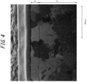
- FIG. 4 illustrates a SIM image of the interface between the Fe-based electroplating layer and the Si-containing cold-rolled steel sheet for Example No. 31 described below.
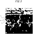
- FIG. 5 illustrates an image after the SIM image has been subjected to image processing and binarization processing as described above.
- the crystal orientations of the Fe-based electroplating layer and the Si-containing cold-rolled steel sheet were integrated at a ratio of 97 % at the interface between the Fe-based electroplating layer and the Si-containing cold-rolled steel sheet.
- FIG. 6 illustrates a SIM image of the interface between the Fe-based electroplating layer and the Si-containing cold-rolled steel sheet for Example No. 34 described below.
- FIG. 34 illustrates a SIM image of the interface between the Fe-based electroplating layer and the Si-containing cold-rolled steel sheet for Example No. 34 described below.
- Example 7 illustrates an image after the SIM image has been subjected to image processing and binarization processing as described above.
- Example No. 34 the crystal orientations of the Fe-based electroplating layer and the Si-containing cold-rolled steel sheet were integrated at a ratio of 95 % at the interface between the Fe-based electroplating layer and the Si-containing cold-rolled steel sheet.
- the present disclosure it is possible to provide a high-strength Fe-based electroplated steel sheet with a tensile strength TS of 590 MPa or more when measured in accordance with JIS Z 2241 (2011).
- the strength of the Fe-based electroplating steel sheet is more preferably 800 MPa or more.
- the thickness of the Fe-based electroplated steel sheet in this embodiment is not particularly limited, yet may usually be 0.5 mm or more and 3.2 mm or less.
- a cold-rolled steel sheet containing Si in an amount of 0.1 mass% or more and 3.0 mass% or less is produced.
- the cold-rolled steel sheet may contain Si in an amount of 0.50 mass% or more and 3.0 mass% or less.
- conventional methods may be followed.
- a cold-rolled steel sheet is produced by hot rolling a steel slab having the chemical composition described above to obtain a hot-rolled sheet, then subjecting the hot-rolled sheet to acid cleaning, and then cold rolling the hot-rolled sheet to obtain a cold-rolled steel sheet.
- the Fe-based electroplating is not limited to a particular method.
- a sulfuric acid bath, a hydrochloric acid bath, or a mixture of the two can be used as an Fe-based electroplating bath.
- pre-annealing Fe-based electroplated steel sheet means that the Fe-based electroplating layer has not undergone an annealing process, and does not exclude the cold-rolled steel sheet having been annealed before subjection to Fe-based electroplating.
- the Fe ion content in the Fe-based electroplating bath before the start of current passage is preferably 0.5 mol/L or more as Fe 2+ . If the Fe ion content in the Fe-based electroplating bath is 0.5 mol/L or more as Fe 2+ , a sufficient Fe coating weight can be obtained. In order to obtain a sufficient Fe coating weight, the Fe ion content in the Fe-based electroplating bath before the start of current passage is preferably 2.0 mol/L or less.
- the Fe-based electroplating bath may contain Fe ions and at least one element selected from the group consisting of B, C, P, N, O, Ni, Mn, Mo, Zn, W, Pb, Sn, Cr, V, and Co.
- the total content of these elements in the Fe-based electroplating bath is preferably adjusted so that the total content of these elements in the pre-annealing Fe-based electroplating layer is 10 mass% or less.
- Metallic elements may be contained as metal ions, while non-metallic elements may be contained as part of, for example, boric acid, phosphoric acid, nitric acid, or organic acid.
- the iron sulfate plating solution may also contain conductivity aids such as sodium sulfate and potassium sulfate, chelating agents, or pH buffers.
- the temperature of the Fe-based electroplating solution is preferably 30 °C or higher, and it is preferably 85 °C or lower, for constant temperature retention.
- the pH of the Fe-based electroplating bath is not specified, it is preferably 1.0 or more from the viewpoint of preventing a decrease in current efficiency due to hydrogen generation. In addition, it is preferably 3.0 or less considering the electrical conductivity of the Fe-based electroplating bath.
- the current density is preferably 10 A/dm 2 or higher for productivity. It is preferably 150 A/dm 2 or lower for ease of control of coating weight of the Fe-based electroplating layer.
- the sheet passing speed is preferably 5 mpm or higher for productivity. It is preferably 150 mpm or lower for stable control of coating weight.
- degreasing and water washing may be performed to clean the surface of the cold-rolled steel sheet, and acid cleaning and water washing may also be performed to activate the surface of the cold-rolled steel sheet. Following these pretreatments, Fe-based electroplating is performed.
- the methods of degreasing and water washing are not limited, and conventional methods may be followed.
- Various acids such as sulfuric acid, hydrochloric acid, nitric acid, and mixtures of these acids can be used in the acid cleaning. Among these preferred are sulfuric acid, hydrochloric acid, or a mixture of these.
- the acid concentration is not specified, approximately 1 mass% to 20 mass% is preferable considering the ability to remove oxide coating and the prevention of rough skin (surface defects) due to excessive acid cleaning.
- the acid cleaning solution may also contain, for example, a defoamer, an acid cleaning promoter, or an acid cleaning inhibitor.
- the pre-annealing Fe-based electroplated steel sheet is subjected to an annealing process in which the steel sheet is held in a temperature range of 650 °C to 900 °C for 30 seconds to 600 seconds in a reducing atmosphere with a dew point of -30 °C or lower and a hydrogen concentration from 1.0 vol.% to 30.0 vol.%, and then cooled to obtain an Fe-based electroplated steel sheet.
- the annealing process is performed to increase the strength of the steel sheet by relieving the stress in the pre-annealing Fe-based electroplated steel sheet caused by the rolling process and recrystallizing the microstructure of the pre-annealing Fe-based electroplated steel sheet.
- the dew point of the annealing atmosphere in the annealing process is a low dew point of -30 °C or lower, which is a condition that requires no additional equipment such as humidification equipment. It is preferable to control the dew point to -30 °C or lower in a temperature range of 650 °C to 900 °C. According to our original study, we have found that there is a correlation between the ratio at which the crystal orientations of the Fe-based electroplating layer and the Si-containing cold-rolled steel sheet are integrated at the interface between the Fe-based electroplating layer and the Si-containing cold-rolled steel sheet and the dew point of the annealing atmosphere in the annealing process after the formation of the Fe-based electroplating layer.
- the ratio at which the crystal orientations of the Fe-based electroplating layer and the Si-containing cold-rolled steel sheet are integrated of the Fe-based electroplated steel sheet obtained after annealing increases as the dew point of the annealing atmosphere decreases, and the ratio at which the crystal orientations of the Fe-based electroplating layer and the Si-containing cold-rolled steel sheet are integrated decreases as the dew point of the annealing atmosphere increases.
- the crystal orientation of the Fe-based electroplating layer integrates with the crystal orientation of the Si-containing cold-rolled steel sheet at a high ratio when annealing is performed at a low dew point.
- the ratio at which the crystal orientations of the Fe-based electroplating layer and the Si-containing cold-rolled steel sheet are integrated at the interface between the Fe-based electroplating layer and the Si-containing cold-rolled steel sheet increases. Accordingly, when it is combined with a galvanized steel sheet, zinc melted during resistance welding easily penetrates into the crystal grain boundaries in the Si-containing cold-rolled steel sheet via the crystal grain boundaries in the Fe-based electroplating layer.
- forming an Fe-based electroplating layer with a certain coating weight delays the time for the zinc melted during resistance welding to reach the crystal grain boundaries in the Si-containing cold-rolled steel sheet via the crystal grain boundaries in the Fe-based electroplating layer when combined with a galvanized steel sheet, thereby improving the resistance to cracking in resistance welding at a welded portion.
- the lower limit of the dew point of the annealing atmosphere is not specified, yet it is preferably -80 °C or higher because it is industrially difficult to achieve a dew point lower than -80 °C.
- the dew point of the annealing atmosphere is more preferably -55 °C or higher.
- the annealing process is performed in a reducing atmosphere with a hydrogen concentration of 1.0 vol.% or more and 30.0 vol.% or less. Hydrogen plays a role in suppressing the oxidation of Fe on the surface of the pre-annealing Fe-based electroplated steel sheet during the annealing process and activating the steel sheet surface. If the hydrogen concentration is 1.0 vol.% or more, it is possible to avoid the deterioration of the chemical convertibility, which would otherwise be caused by the oxidation of Fe on the steel sheet surface when a chemical conversion layer is formed as described below. Therefore, the annealing process is performed in a reducing atmosphere with a hydrogen concentration of preferably 1.0 vol.% or more, and more preferably 2.0 vol.% or more.
- the hydrogen concentration in the annealing process is not particularly limited, from the cost perspective, the hydrogen concentration is preferably 30.0 vol.% or less, and more preferably 20.0 vol.% or less.
- the balance of the annealing atmosphere other than hydrogen is preferably nitrogen.
- the holding time in the temperature range of 650 °C to 900 °C is preferably from 30 seconds to 600 seconds.
- the holding time in this temperature range is preferably 30 seconds or more.
- the upper limit of the holding time in this temperature range is not specified, yet from the viewpoint of productivity, the holding time in this temperature range is preferably 600 seconds or less.
- the maximum arrival temperature of the pre-annealing Fe-based electroplated steel sheet is not particularly limited, yet it is preferably from 650 °C to 900 °C.
- the maximum arrival temperature of the pre-annealing Fe-based electroplated steel sheet is preferably from 650 °C to 900 °C.
- recrystallization of the microstructure of the steel sheet can suitably proceed and the desired strength can be obtained.
- the natural oxide layer of Fe formed on the surface of the pre-annealing Fe-based electroplating layer can be suitably reduced, improving the chemical convertibility when forming a chemical conversion layer on the surface of the Fe-based electroplated steel sheet as described below.
- the maximum arrival temperature of the Fe-based electroplated steel sheet is preferably 900 °C or lower. The maximum arrival temperature is based on the temperature measured on the surface of the pre-annealing Fe-based electroplated steel sheet.
- an electrodeposition-coated steel sheet comprising: a chemical conversion layer formed on the aforementioned Fe-based electroplated steel sheet so as to contact the Fe-based electroplating layer; and an electrodeposition coating layer formed on the chemical conversion layer.
- the Fe-based electroplated steel sheet in this embodiment has excellent resistance to cracking in resistance welding at a welded portion. Therefore, an electrodeposition-coated steel sheet formed using the Fe-based electroplated steel sheet disclosed herein is particularly suitable for application to automotive parts. It is preferable that the electrodeposition-coated steel sheet in this embodiment have a chemical conversion layer formed directly on the Fe-based electroplating layer.
- the electrodeposition-coated steel sheet in this embodiment have no additional coated or plated layer besides the Fe-based electroplating layer.
- the types of the chemical conversion layer and the electrodeposition coating layer are not limited, and publicly known chemical conversion layers and electrodeposition coating layers may be used.
- the chemical conversion layer may be, for example, a zinc phosphate layer or a zirconium layer.
- the electrodeposition coating layer is not limited as long as it is an electrodeposition coating layer for automotive use.
- the thickness of the electrodeposition coating layer varies depending on the application. However, it is preferably about 10 ⁇ m or more in the dry state. It is preferably about 30 ⁇ m or less in the dry state. According to this embodiment, it is also possible to provide an Fe-based electroplated steel sheet for electrodeposition coating to apply electrodeposition coating.
- the aforementioned electrodeposition-coated steel sheet may be produced with a method of producing an electrodeposition-coated steel sheet, the method comprising: subjecting the Fe-based electroplated steel sheet to chemical conversion treatment, without additional coating or plating treatment, to obtain a chemical-conversion-treated steel sheet with a chemical conversion layer formed in contact with the Fe-based electroplating layer; and subjecting the chemical-conversion-treated steel sheet to electrodeposition coating treatment to obtain an electrodeposition-coated steel sheet with an electrodeposition coating layer formed on the chemical conversion layer.
- the chemical conversion treatment and electrodeposition coating treatment conventional methods may be followed.
- degreasing, water washing, and if necessary, surface conditioning treatment may be performed to clean the surface of the Fe-based electroplated steel sheet. These pretreatments are followed by the chemical conversion treatment.
- the methods of degreasing and water washing are not limited, and conventional methods may be followed.
- surface conditioners containing Ti colloids or zinc phosphate colloids can be used, for example.
- no special process is required and conventional methods may be followed.
- the desired surface conditioner is dissolved in a certain deionized water and stirred thoroughly to obtain a treatment solution at a predetermined temperature (usually room temperature, i.e., 25 °C to 30 °C).
- the steel sheet is immersed in the obtained treatment solution for a predetermined time (e.g., 20 seconds to 30 seconds).
- the steel sheet is then subjected to the subsequent chemical conversion treatment without being dried.
- the chemical conversion treatment conventional methods may be followed.
- the desired chemical conversion treatment agent is dissolved in a certain deionized water and stirred thoroughly to obtain a treatment solution at a predetermined temperature (usually 35 °C to 45 °C).
- a predetermined time e.g. 60 seconds to 120 seconds.
- a zinc phosphate treatment agent for steel for example, a zinc phosphate treatment agent for combined use of steel and aluminum, or a zirconium treatment agent may be used.
- the steel sheet is then subjected to the subsequent electrodeposition coating.
- conventional methods may be followed. After pretreatment such as water washing, if necessary, the steel sheet is immersed in an electrodeposition coating material that has been thoroughly stirred to obtain the desired thickness of electrodeposition coating by electrodeposition treatment.
- the electrodeposition coating anionic electrodeposition coating as well as cationic electrodeposition coating can be used.
- top coating may be applied after the electrodeposition coating, depending on the application.
- an automotive part that is at least partially made from the electrodeposition-coated steel sheet described above.
- the Fe-based electroplated steel sheet in this embodiment has excellent resistance to cracking in resistance welding at a welded portion. Therefore, an electrodeposition-coated steel sheet using the Fe-based electroplated steel sheet disclosed herein is particularly suitable for application to automotive parts.
- the automotive part made from the electrodeposition-coated steel sheet may contain a steel sheet other than the electrodeposition-coated steel sheet in this embodiment as the raw material.
- the electrodeposition-coated steel sheet in this embodiment has excellent resistance to cracking in resistance welding at a welded portion, cracking is suitably prevented from occurring at a welded portion even when the automotive part made from the Fe-based electroplated steel sheet includes a high-strength hot-dip galvanized steel sheet as a welding counterpart.
- the types of the automotive part at least partially made from the electrodeposition-coated steel sheet are not limited. However, the automotive part may be, for example, a side sill part, a pillar part, or an automotive body.
- the cold-rolled steel sheet is a cold-rolled steel sheet where a test specimen of the cold-rolled steel sheet that is cut to a size of 50 mm ⁇ 150 mm with a direction orthogonal to the rolling direction as the lengthwise direction is overlapped with a test galvannealed steel sheet that is cut to the same size having a hot-dip galvanized layer with a coating weight per surface of 50 g/m 2 to obtain a sheet combination,
- the cold-rolled steel sheet in this embodiment is not particularly limited if it is a steel sheet inferior in resistance to cracking in resistance welding at a welded portion when combined with a galvanized steel sheet and evaluated by the following test.
- the chemical composition of the cold-rolled steel sheet is not particularly limited. We have found that a cold-rolled steel sheet containing Si in an amount of 0.1 mass% or more in the steel is inferior in resistance to cracking in resistance welding at a welded portion when evaluated by the following test.
- the cold-rolled steel sheet may be a cold-rolled steel sheet where the sheet combination with a welded portion is obtained by performing the resistance welding at a hold time of 0.24 seconds, a cross section of the welded portion is observed under an optical microscopy (magnification 200x), and a crack as long as 0.1 mm or more is observed.
- the resistance to cracking in resistance welding at a welded portion generally deteriorates as the hold time decreases.
- a test specimen 6 that is cut to a size of 50 mm ⁇ 150 mm with the transverse direction ("TD", direction orthogonal to the rolling direction) as the lengthwise direction and the rolling direction as the widthwise direction is overlapped with a test galvannealed steel sheet 5 that is cut to the same size having a hot-dip galvanized layer with a coating weight per surface of 50 g/m 2 .
- the sheet combination is assembled so that the surface to be evaluated (Fe-based electroplated layer) of the test specimen 6 and the galvanized layer of the test galvannealed steel sheet 5 face each other.
- the sheet combination is fixed to a fixing stand 8 via spacers 7 of 2.0 mm thick.
- the spacers 7 are a pair of steel sheets, each measuring 50 mm long (lengthwise direction) ⁇ 45 mm wide (widthwise direction) ⁇ 2.0 mm thick (thickness direction). As illustrated in FIG. 8A , the lengthwise end faces of the pair of steel sheets are aligned with the widthwise end faces of the sheet combination. Thus, the distance between the pair of steel sheets is 60 mm.
- the fixing stand 8 is a single plate with a hole in the center.
- the sheet combination is subjected to resistance welding at a welding current and a welding time that result in a nugget diameter r of 5.9 mm while being deflected by applying pressure with a pair of electrodes 9 (tip diameter: 6 mm) under the conditions of an applied pressure of 3.5 kN and a hold time of 0.18 seconds or 0.24 seconds, to form a sheet combination with a welded portion.
- the pair of electrodes 9 pressurize the sheet combination from above and below in the vertical direction, with the lower electrode pressurizing the test specimen 6 through the hole in the fixing stand 8.
- the lower electrode of the pair of electrodes 9 and the fixing stand 8 are fixed, and the upper electrode is movable so that the lower electrode is in contact with a plane that is an extension of a plane where the spacer 7 touches the fixing stand 8.
- the upper electrode is in contact with the center of the test galvannealed steel sheet 5.
- the sheet combination is welded with the sheet combination inclined 5° to the lengthwise direction side of the sheet combination with respect to a plane perpendicular to a line connecting the central axes of the electrode pair of the resistance welding machine (horizontal direction in FIG. 8A ).
- a gap of 60 mm in the lengthwise direction of the sheet combination and 2.0 mm in the thickness direction of the sheet combination is formed between the lower electrode and the test specimen 6 by the spacers.
- the hold time refers to the time between the end of welding current and the beginning of release of the electrodes.
- the nugget diameter r means the distance between the ends of a nugget 10 in the lengthwise direction of the sheet combination.
- the sheet combination with a welded portion is cut along the B-B line indicated in the upper part of FIG. 8B to include the center of the welded portion including the nugget 10, and the cross section of the welded portion is observed under an optical microscopy (200x) to evaluate the resistance to cracking in resistance welding at the welded portion using the following criteria. If the result is ⁇ or O, the sheet combination is judged to have satisfactory resistance to cracking in resistance welding at the welded portion. If the result is ⁇ , the sheet combination is judged to have poor resistance to cracking in resistance welding at the welded portion.
- the resistance to cracking in resistance welding at the welded portion may be evaluated using the following criteria under milder welding conditions.
- FIG. 12B An example of a crack in the test specimen 6 is schematically illustrated in the lower part of FIG. 12B, as indicated by reference numeral 11.
- the Fe-based electroplating layer of the Fe-based electroplated steel sheet in this embodiment is the same as in the Embodiment 1 described above, and the description thereof is omitted.
- the crystal orientations of the Fe-based electroplating layer and the cold-rolled steel sheet are integrated at a ratio of more than 50 % at the interface between the Fe-based electroplating layer and the cold-rolled steel sheet, as in the Embodiment 1 described above.
- the details of the ratio at which the crystal orientations of the Fe-based electroplating layer and the cold-rolled steel sheet are integrated at the interface between the Fe-based electroplating layer and the cold-rolled steel sheet are the same as in the Embodiment 1 described above, and the description thereof is omitted.
- the cold-rolled steel sheet is a cold-rolled steel sheet where a test specimen of the cold-rolled steel sheet that is cut to a size of 50 mm ⁇ 150 mm with a direction orthogonal to the rolling direction as the lengthwise direction is overlapped with a test galvannealed steel sheet that is cut to the same size having a hot-dip galvanized layer with a coating weight per surface of 50 g/m 2 to obtain a sheet combination,
- a cold-rolled steel sheet is produced.
- conventional methods may be followed.
- a cold-rolled steel sheet is produced by hot rolling a steel slab to obtain a hot-rolled sheet, then subjecting the hot-rolled sheet to acid cleaning, and then cold rolling the hot-rolled sheet to obtain a cold-rolled steel sheet.
- the cold-rolled steel sheet according to this embodiment is not particularly limited if it is a steel sheet inferior in resistance to cracking in resistance welding at a welded portion when combined with a galvanized steel sheet and evaluated by the test described above.
- the chemical composition of the cold-rolled steel sheet is not particularly limited, either. If it is a cold-rolled steel sheet containing Si in an amount of 0.1 mass% or more in the steel, it is inferior in resistance to cracking in resistance welding at a welded portion when evaluated by the test described above.
- the cold-rolled steel sheet may be a cold-rolled steel sheet where the sheet combination with a welded portion is obtained by performing the resistance welding at a hold time of 0.24 seconds, a cross section of the welded portion is observed under an optical microscopy (magnification 200x), and a crack as long as 0.1 mm or more is observed.
- the resistance to cracking in resistance welding at a welded portion generally deteriorates as the hold time decreases.
- the surface of the cold-rolled steel sheet is subjected to Fe-based electroplating to obtain a pre-annealing Fe-based electroplated steel sheet.
- Fe-based electroplating treatment The details of the Fe-based electroplating treatment have been described above, and the description thereof is omitted.
- the pre-annealing Fe-based electroplated steel sheet is subjected to an annealing process in which the steel sheet is held in a temperature range of 650 °C to 900 °C for 30 seconds to 600 seconds in a reducing atmosphere with a dew point of -30 °C or lower and a hydrogen concentration from 1.0 vol.% to 30.0 vol.%, and then cooled to obtain an Fe-based electroplated steel sheet.
- the details of the annealing process have been described above, and the description thereof is omitted.
- an electrodeposition-coated steel sheet comprising: a chemical conversion layer formed on the Fe-based electroplated steel sheet in this embodiment so as to contact the Fe-based electroplating layer; and an electrodeposition coating layer formed on the chemical conversion layer, as in the Embodiment 1 described above. Further, it is possible to provide an Fe-based electroplated steel sheet for electrodeposition coating to apply electrodeposition coating.
- the details of the electrodeposition-coated steel sheet and a method of producing the electrodeposition-coated steel sheet are the same as in the Embodiment 1 described above, and the description thereof is omitted.
- this embodiment also can provide an automotive part, as in the Embodiment 1 described above.
- the details of the automotive part have been described above, and the description thereof is omitted.
- Cast steel samples were prepared by smelting steel with the chemical compositions listed in Tables 1 and 3, and they were subjected to hot rolling, acid cleaning, and cold rolling to obtain cold-rolled steel sheets with a thickness of 1.6 mm.
- each cold-rolled steel sheet was subjected to degreasing with alkali, followed by electrolytic treatment with the steel sheet as the cathode under the conditions described below to produce a pre-annealing Fe-based electroplated steel sheet having an Fe-based electroplating layer on one surface.
- the coating weight of the Fe-based electroplating layer was controlled by current passage time.
- the pre-annealing Fe-based electroplated steel sheets were subjected to reduction annealing at 15 % H 2 -N 2 and a soaking zone temperature of 800 °C, with the dew point of the atmosphere adjusted as listed in Tables 2-1, 2-2, and 4, to obtain Fe-based electroplated steel sheets.
- the reduction annealing was performed for 100 seconds.
- the coating weight per surface of the Fe-based electroplating layer, and the ratio at which the crystal orientations of the Fe-based electroplating layer and the Si-containing cold-rolled steel sheet are integrated at the interface between the Fe-based electroplating layer and the Si-containing cold-rolled steel sheet were determined according to the methods described above.
- the resistance to cracking in resistance welding at a welded portion was also investigated for each Fe-based electroplated steel sheet thus prepared. The following describes the measurement and evaluation methods of the resistance to cracking in resistance welding at a welded portion.
- the resistance to cracking in resistance welding at a welded portion was evaluated with the method described above when combined with a test galvannealed steel sheet (1.6 mm thick) having a tensile strength of 980 MPa and a coating weight per surface of 50 g/m 2 , with a Si content of less than 0.50 %, where the resistance to cracking in resistance welding was not an issue at a hold time of 0.18 seconds.
- the welding time was 0.36 seconds and the hold times were 0.18 seconds and 0.24 seconds.
- the nugget diameter was measured by changing the welding current for each Example No., and the evaluation was performed at the welding current where the nugget diameter was 5.9 mm.
- the coating weight of the Fe-based electroplating layer is indicated as "-" for the examples where no Fe-based electroplating layer was formed.
- Reference Examples No. 17, 30, and 46 where annealing processes at high dew point were performed the ratio at which the crystal orientations of the Fe-based electroplating layer and the Si-containing cold-rolled steel sheet were integrated at the interface between the Fe-based electroplating layer and the Si-containing cold-rolled steel sheet was low because of the annealing at high dew point, and the resistance to cracking in resistance welding at a welded portion was good.
- the pre-annealing Fe-based electroplated steel sheets were heated to a soaking zone temperature of 800 °C at an average heating rate of at least 10 °C/s in the temperature range of 400 °C to 650 °C, and then subjected to reduction annealing.
- Cast steel samples were prepared by smelting steel with the chemical compositions listed in Table 5, and they were subjected to hot rolling, acid cleaning, and cold rolling to obtain cold-rolled steel sheets with a thickness of 1.6 mm.
- each cold-rolled steel sheet was subjected to degreasing with alkali, followed by electrolytic treatment with the steel sheet as the cathode under the conditions described below to produce a pre-annealing Fe-based electroplated steel sheet having an Fe-based electroplating layer on one surface.
- the coating weight of the Fe-based electroplating layer was controlled by current passage time.
- the pre-annealing Fe-based electroplated steel sheets were subjected to reduction annealing at 15 % H 2 -N 2 and a soaking zone temperature of 800 °C, with the dew point of the atmosphere adjusted as listed in Table 6, to obtain Fe-based electroplated steel sheets.
- the reduction annealing was performed for 100 seconds.
- the coating weight per surface of the Fe-based electroplating layer, and the ratio at which the crystal orientations of the Fe-based electroplating layer and the Si-containing cold-rolled steel sheet are integrated at the interface between the Fe-based electroplating layer and the Si-containing cold-rolled steel sheet were determined according to the methods described above.
- the resistance to cracking in resistance welding at a welded portion was also investigated for each Fe-based electroplated steel sheet thus prepared. The following describes the measurement and evaluation methods of the resistance to cracking in resistance welding at a welded portion.
- the resistance to cracking in resistance welding at a welded portion was evaluated with the method described above when combined with a test galvannealed steel sheet (1.6 mm thick) having a tensile strength of 590 MPa and a coating weight per surface of 50 g/m 2 , with a Si content of less than 0.1 %, where the resistance to cracking in resistance welding was not an issue at a hold time of 0.14 seconds.
- the welding time was 0.36 seconds and the hold times were 0.14 seconds and 0.16 seconds.
- the nugget diameter was measured by changing the welding current for each Example No., and the evaluation was performed at the welding current where the nugget diameter was 5.9 mm.
- the Fe-based electroplated steel sheet produced with the method disclosed herein not only has excellent resistance to cracking in resistance welding, especially internal cracking, at a welded portion when combined with a galvanized steel sheet, but also has high strength and excellent formability, making it suitable not only as the raw material used in automotive parts but also as the raw material for applications requiring similar properties in fields such as home appliances and construction materials.
Landscapes
- Chemical & Material Sciences (AREA)
- Engineering & Computer Science (AREA)
- Organic Chemistry (AREA)
- Materials Engineering (AREA)
- Metallurgy (AREA)
- Mechanical Engineering (AREA)
- Chemical Kinetics & Catalysis (AREA)
- Electrochemistry (AREA)
- Crystallography & Structural Chemistry (AREA)
- Physics & Mathematics (AREA)
- Thermal Sciences (AREA)
- General Chemical & Material Sciences (AREA)
- Electroplating Methods And Accessories (AREA)
- Heat Treatment Of Sheet Steel (AREA)
- Other Surface Treatments For Metallic Materials (AREA)
- Resistance Welding (AREA)
Abstract
Description
- This disclosure relates to an Fe-based electroplated steel sheet with excellent resistance to cracking in resistance welding, an electrodeposition-coated steel sheet, an automotive part, a method of producing an electrodeposition-coated steel sheet, and a method of producing an Fe-based electroplated steel sheet.
- In recent years, there has been a strong demand to improve the fuel efficiency of automobiles from the viewpoint of protecting the global environment. In addition, there has been a strong demand for improved automobile safety from the viewpoint of ensuring occupant safety in the event of a collision. In order to meet these demands, it is necessary to achieve lightweight and high-strength automotive bodies, and the use of high-strength cold-rolled steel sheets as the material for automotive parts is being actively promoted to achieve sheet metal thinning. However, since most automotive parts are manufactured by forming steel sheets, these steel sheets are required to have excellent formability in addition to high strength.
- There are various methods to increase the strength of cold-rolled steel sheets. One method that can increase strength without significantly compromising the formability of cold-rolled steel sheets is solid solution strengthening by adding Si. On the other hand, in the manufacture of automotive parts, press-formed parts are often combined by resistance welding (spot welding). If the part to be subjected to resistance welding contains a high-strength galvanized steel sheet, there is concern that liquid metal embrittlement (LME) may occur during resistance welding when residual stresses are generated in the vicinity of a welded portion and the zinc in the coated or plated layer melts and diffuses into crystal grain boundaries, resulting in intergranular cracking (or LME cracking) in the steel sheet. In particular, if welding is performed with the welding electrode at an angle to the steel sheet, residual stresses may increase and cracks may form. Residual stresses are expected to increase with higher strength of the steel sheet, and thus there is concern about LME cracking associated with higher strength of the steel sheet. The problem is that even if a high-strength steel sheet does not have a galvanized layer, if the counterpart steel sheet to be welded is a galvanized steel sheet, the galvanized layer thereof melts and LME cracking can occur in the steel sheet without a galvanized layer. This problem of LME cracking is particularly pronounced in steel sheets containing Si.
- Therefore, there is a need for a high-strength steel sheet with excellent resistance to cracking in resistance welding at a welded portion when combined with a galvanized steel sheet (hereinafter referred to simply as "resistance to cracking in resistance welding at a welded portion").
- Conventionally, remedial measures for the above issues have been reported. For example,
JP 6388099 B - PTL 1:
JP 6388099 B - We have newly found that forming an Fe-based electroplating layer on the surface of a cold-rolled steel sheet can improve the resistance to cracking in resistance welding. On the other hand, we also have found that, when annealing is performed after the formation of the Fe-based electroplating layer, the crystal orientations of the Fe-based electroplating layer and the cold-rolled steel sheet are integrated at a high ratio at the interface between the Fe-based electroplating layer and the cold-rolled steel sheet depending on the annealing conditions. We have found that, when such an Fe-based electroplated steel sheet is combined with a galvanized steel sheet, molten zinc easily penetrates into the crystal grain boundaries in the cold-rolled steel sheet via the crystal grain boundaries in the Fe-based electroplating layer. This is not described in
PTL 1 at all. - It could thus be helpful to provide a steel sheet with excellent resistance to cracking in resistance welding at a welded portion, even if the crystal orientations of an Fe-based electroplating layer and a Si-containing cold-rolled steel sheet are integrated at a high ratio at the interface between the Fe-based electroplating layer and the cold-rolled steel sheet.
- In order to solve the above problem, we have made intensive studies and found that it is important to form an Fe-based electroplating layer with a coating weight per surface of more than 20.0 g/m2 on a surface of a cold-rolled steel sheet after subjection to cold rolling and before subjection to continuous annealing to satisfy a high level of resistance to cracking in resistance welding at a welded portion. We have found that forming a soft Fe-based electroplating layer with a coating weight of more than 20.0 g/m2 per surface of the cold-rolled steel sheet reduces the stress applied to the steel sheet surface during welding, and, when the cold-rolled steel sheet contains Si, the Fe-based electroplating layer can act as a layer deficient in solute Si to suppress the decrease in toughness due to solid dissolution of Si and improve the resistance to cracking in resistance welding at a welded portion, thereby completing the present disclosure.
- The present disclosure is based on the aforementioned discoveries. Specifically, primary features of the present disclosure are as follows.
- [1] An Fe-based electroplated steel sheet comprising:
- a Si-containing cold-rolled steel sheet containing Si in an amount of 0.1 mass% or more and 3.0 mass% or less; and
- an Fe-based electroplating layer formed on at least one surface of the Si-containing cold-rolled steel sheet with a coating weight per surface of more than 20.0 g/m2, wherein
- crystal orientations of the Fe-based electroplating layer and the Si-containing cold-rolled steel sheet are integrated at a ratio of more than 50 % at an interface between the Fe-based electroplating layer and the Si-containing cold-rolled steel sheet.
- [2] The Fe-based electroplated steel sheet according to aspect [1], wherein the Si-containing cold-rolled steel sheet contains Si in an amount of 0.50 mass% or more and 3.0 mass% or less.
- [3] The Fe-based electroplated steel sheet according to aspect [1] or [2], wherein the Fe-based electroplating layer is formed with a coating weight per surface of 25.0 g/m2 or more.
- [4] The Fe-based electroplated steel sheet according to any one of aspects [1] to [3], wherein the Si-containing cold-rolled steel sheet has a chemical composition containing, in addition to Si, in mass%,
- C: 0.8 % or less,
- Mn: 1.0 % or more and 12.0 % or less,
- P: 0.1 % or less,
- S: 0.03 % or less,
- N: 0.010 % or less, and
- Al: 1.0 % or less, with the balance being Fe and inevitable impurities.
- [5] The Fe-based electroplated steel sheet according to aspect [4], wherein the chemical composition further contains at least one selected from the group consisting of
- B: 0.005 % or less,
- Ti: 0.2 % or less,
- Cr: 1.0 % or less,
- Cu: 1.0 % or less,
- Ni: 1.0 % or less,
- Mo: 1.0 % or less,
- Nb: 0.20 % or less,
- V: 0.5 % or less,
- Sb: 0.200 % or less,
- Ta: 0.1 % or less,
- W: 0.5 % or less,
- Zr: 0.1 % or less,
- Sn: 0.20 % or less,
- Ca: 0.005 % or less,
- Mg: 0.005 % or less, and
- REM: 0.005 % or less.
- [6] The Fe-based electroplated steel sheet according to any one of aspects [1] to [5], wherein the Fe-based electroplating layer has a chemical composition containing at least one element selected from the group consisting of B, C, P, N, O, Ni, Mn, Mo, Zn, W, Pb, Sn, Cr, V, and Co, in a total amount of 10 mass% or less, with the balance being Fe and inevitable impurities.
- [7] An Fe-based electroplated steel sheet comprising:
- a cold-rolled steel sheet; and
- an Fe-based electroplating layer formed on at least one surface of the cold-rolled steel sheet with a coating weight per surface of more than 20.0 g/m2, wherein
- crystal orientations of the Fe-based electroplating layer and the cold-rolled steel sheet are integrated at a ratio of more than 50 % at an interface between the Fe-based electroplating layer and the cold-rolled steel sheet.
- As used herein, the cold-rolled steel sheet is a cold-rolled steel sheet where a test specimen of the cold-rolled steel sheet that is cut to a size of 50 mm × 150 mm with a direction orthogonal to a rolling direction as a lengthwise direction is overlapped with a test galvannealed steel sheet that is cut to the same size having a hot-dip galvanized layer with a coating weight per surface of 50 g/m2 to obtain a sheet combination,
- next, using a 50-Hz single-phase AC resistance welding machine of servomotor pressure type, the sheet combination is inclined 5° to a lengthwise direction side of the sheet combination with respect to a plane perpendicular to a line connecting central axes of an electrode pair with a tip diameter of 6 mm of the resistance welding machine, a lower electrode of the electrode pair and the sheet combination are fixed so that a gap of 60 mm in a lengthwise direction of the sheet combination and 2.0 mm in a thickness direction of the sheet combination is provided between the lower electrode and the test specimen, an upper electrode of the electrode pair is movable, and resistance welding is applied to the sheet combination under a set of conditions: applied pressure: 3.5 kN, hold time: 0.16 seconds, and welding current and welding time to produce a nugget diameter of 5.9 mm, to obtain a sheet combination with a welded portion, and
- the sheet combination with a welded portion is then cut in half along a lengthwise direction of the test specimen to include a welded portion, a cross section of the welded portion is observed under an optical microscopy at a magnification of 200x, and a crack as long as 0.1 mm or more is observed.
- [8] The Fe-based electroplated steel sheet according to aspect [7], wherein the cold-rolled steel sheet is a cold-rolled steel sheet where the sheet combination with a welded portion is obtained by performing the resistance welding with the hold time being 0.24 seconds, a cross section of the welded portion is observed under the optical microscopy at a magnification of 200x, and a crack as long as 0.1 mm or more is observed.
- [9] An electrodeposition-coated steel sheet comprising: a chemical conversion layer formed on the Fe-based electroplated steel sheet as recited in any one of aspects [1] to [8] so as to contact the Fe-based electroplating layer; and an electrodeposition coating layer formed on the chemical conversion layer.
- [10] An automotive part at least partially made from the electrodeposition-coated steel sheet as recited in aspect [9].
- [11] A method of producing an electrodeposition-coated steel sheet, the method comprising:
- subjecting the Fe-based electroplated steel sheet as recited in any one of aspects [1] to [8] to chemical conversion treatment, without additional coating or plating treatment, to obtain a chemical-conversion-treated steel sheet with a chemical conversion layer formed in contact with the Fe-based electroplating layer; and
- subjecting the chemical-conversion-treated steel sheet to electrodeposition coating treatment to obtain an electrodeposition-coated steel sheet with an electrodeposition coating layer formed on the chemical conversion layer.
- [12] A method of producing an Fe-based electroplated steel sheet, the method comprising:
- subjecting a cold-rolled steel sheet containing Si in an amount of 0.1 mass% or more and 3.0 mass% or less to Fe-based electroplating to obtain a pre-annealing Fe-based electroplated steel sheet with a pre-annealing Fe-based electroplating layer formed on at least one surface thereof with a coating weight per surface of more than 20.0 g/m2; and
- then subjecting the pre-annealing Fe-based electroplated steel sheet to annealing in an atmosphere with a dew point of -30 °C or lower to obtain an Fe-based electroplated steel sheet.
- [13] The method of producing an Fe-based electroplated steel sheet according to aspect [12], wherein the cold-rolled steel sheet contains Si in an amount of 0.5 mass% or more and 3.0 mass% or less.
- [14] A method of producing an Fe-based electroplated steel sheet, the method comprising:
- subjecting a cold-rolled steel sheet to Fe-based electroplating to obtain a pre-annealing Fe-based electroplated steel sheet with a pre-annealing Fe-based electroplating layer formed on at least one surface thereof with a coating weight per surface of more than 20.0 g/m2; and
- then subjecting the pre-annealing Fe-based electroplated steel sheet to annealing to obtain an Fe-based electroplated steel sheet.
- As used herein, the cold-rolled steel sheet is a cold-rolled steel sheet where a test specimen of the cold-rolled steel sheet that is cut to a size of 50 mm × 150 mm with a direction orthogonal to a rolling direction as a lengthwise direction is overlapped with a test galvannealed steel sheet that is cut to the same size having a hot-dip galvanized layer with a coating weight per surface of 50 g/m2 to obtain a sheet combination,
- next, using a 50-Hz single-phase AC resistance welding machine of servomotor pressure type, the sheet combination is inclined 5° to a lengthwise direction side of the sheet combination with respect to a plane perpendicular to a line connecting central axes of an electrode pair with a tip diameter of 6 mm of the resistance welding machine, a lower electrode of the electrode pair and the sheet combination are fixed so that a gap of 60 mm in a lengthwise direction of the sheet combination and 2.0 mm in a thickness direction of the sheet combination is provided between the lower electrode and the test specimen, an upper electrode of the electrode pair is movable, and resistance welding is applied to the sheet combination under a set of conditions: applied pressure: 3.5 kN, hold time: 0.16 seconds, and welding current and welding time to produce a nugget diameter of 5.9 mm, to obtain a sheet combination with a welded portion, and
- the sheet combination with a welded portion is then cut in half along a lengthwise direction of the test specimen to include a welded portion, a cross section of the welded portion is observed under an optical microscopy at a magnification of 200x, and a crack as long as 0.1 mm or more is observed.
- [15] The method of producing an Fe-based electroplated steel sheet according to aspect [14], wherein the cold-rolled steel sheet is a cold-rolled steel sheet where the sheet combination with a welded portion is obtained by performing the resistance welding with the hold time being 0.24 seconds, a cross section of the welded portion is observed under an optical microscopy at a magnification of 200x, and a crack as long as 0.1 mm or more is observed.
- [16] The method of producing an Fe-based electroplated steel sheet according to any one of aspects [12] to [15], wherein the Fe-based electroplating is performed in an Fe-based electroplating bath containing at least one element selected from the group consisting of B, C, P, N, O, Ni, Mn, Mo, Zn, W, Pb, Sn, Cr, V, and Co, so that the at least one element is contained in the pre-annealing Fe-based electroplating layer in a total amount of 10 mass% or less.
- According to this disclosure, it is possible to provide a steel sheet with excellent resistance to cracking in resistance welding at a welded portion, even if the crystal orientations of an Fe-based electroplating layer and a Si-containing cold-rolled steel sheet are integrated at a high ratio at the interface between the Fe-based electroplating layer and the cold-rolled steel sheet.
- In the accompanying drawings:
-
FIG. 1 schematically illustrates a cross section of an Fe-based electroplated steel sheet; -
FIG. 2A is an oblique overview of a sample for observation to measure the ratio of integrated crystal orientations, andFIG. 2B is an A-A cross section of the sample for observation; -
FIGS. 3A to 3C illustrate a method of evaluating the ratio of integrated crystal orientations, whereFIG. 3A illustrates a boundary line at the interface between an Fe-based electroplating layer and a Si-containing cold-rolled steel sheet in a SIM image,FIG. 3B illustrates a boundary line and an area for evaluation in a binarized image, andFIG. 3C is an enlarged view of the area enclosed by a square inFIG. 3B ; -
FIG. 4 illustrates an image for observing the interface between the Fe-based electroplating layer and the Si-containing cold-rolled steel sheet in Example No. 31; -
FIG. 5 illustrates an image of the interface between the Fe-based electroplating layer and the Si-containing cold-rolled steel sheet in Example No. 31, where a binarized boundary line and a binarized area for evaluation are depicted; -
FIG. 6 illustrates an image for observing the interface between the Fe-based electroplating layer and the Si-containing cold-rolled steel sheet in Example No. 34; -
FIG. 7 illustrates an image of the interface between the Fe-based electroplating layer and the Si-containing cold-rolled steel sheet in Example No. 34, where a binarized boundary line and a binarized area for evaluation are depicted; and -
FIG. 8A illustrates evaluation of resistance to cracking in resistance welding at a welded portion, andFIG. 8B illustrates a top view of a sheet combination after welding in the evaluation in the upper part, and a B-B cross section in the lower part. - The LME cracking described above can be broadly classified into cracking that occurs on the surface in contact with the electrode (hereinafter referred to as "surface cracking") and cracking that occurs near the corona bond between steel sheets (hereinafter referred to as "internal cracking"). It is known that surface cracking is likely to occur in resistance welding at high currents where spatter is generated, and surface cracking can be suppressed by keeping the current within an appropriate range where spatter is not generated. On the other hand, internal cracking occurs even when the current during resistance welding is kept within an appropriate range where spatter is not generated. Surface cracking is easily detected by visual inspection during the manufacturing process, whereas internal cracking is difficult to detect by visual inspection. For these reasons, internal cracking is a particularly significant issue among LME cracking. If resistance welding is performed with the welding electrode at an angle to the steel sheet, residual stresses may increase and internal cracks may form. Since residual stresses are expected to increase as the steel sheet has higher strength, there is concern about internal cracking associated with higher strength of the steel sheet. According to the present disclosure, among the resistance to cracking in resistance welding, the property of preventing such internal cracking can be improved.
- The following describes embodiments of the present disclosure.
- In the following, the units for the content of each element in the chemical composition of the Si-containing cold-rolled steel sheet and the content of each element in the chemical composition of the coated or plated layer are all "mass%", and are simply expressed in "%" unless otherwise specified. As used herein, a numerical range expressed by using "to" means a range including numerical values described before and after "to", as the lower limit value and the upper limit value. As used herein, a steel sheet having "high strength" means that the steel sheet has a tensile strength TS of 590 MPa or higher when measured in accordance with JIS Z 2241 (2011).
-
FIG. 1 schematically illustrates a cross section of an Fe-basedelectroplated steel sheet 1 according to this embodiment. As illustrated inFIG. 1 , the Fe-basedelectroplated steel sheet 1 has an Fe-basedelectroplating layer 3 on at least one surface of a Si-containing cold-rolledsteel sheet 2. First, the chemical composition of the Si-containing cold-rolled steel sheet will be explained. - Si is an effective element for increasing the strength of a steel sheet because it has a large effect of increasing the strength of steel by solid dissolution (i.e., high solid solution strengthening capacity) without significantly impairing formability. On the other hand, Si is also an element that adversely affects the resistance to cracking in resistance welding at a welded portion. When Si is added to increase the strength of a steel sheet, the addition amount needs to be 0.1 % or more. When the Si content is less than 0.50 %, welding at a conventional hold time of about 0.24 seconds will not cause any problem in terms of resistance to cracking in resistance welding at a welded portion. However, the tact time during spot welding in the assembly process of automotive parts has become an issue from the viewpoint of production cost, and when measures are taken to reduce the hold time, the resistance to cracking in resistance welding at a welded portion may become insufficient even if the Si content is less than 0.50 %. On the other hand, if the Si content exceeds 3.0 %, hot rolling manufacturability and cold rolling manufacturability are greatly reduced, which may adversely affect productivity and reduce the ductility of the steel sheet itself. Therefore, Si needs to be added in the range of 0.1 % to 3.0 %. The Si content is preferably 0.50 % or more, more preferably 0.7 % or more, and even more preferably 0.9 % or more. Further, the Si content is preferably 2.5 % or less, more preferably 2.0 % or less, and even more preferably 1.7 % or less.
- The Si-containing cold-rolled steel sheet in this embodiment is required to contain Si in the above range, yet it may contain other components within a range allowable for ordinary cold-rolled steel sheets. The other components are not restricted in any particular way. However, if the Si-containing cold-rolled steel sheet in this embodiment is to be made to have high strength with a tensile strength (TS) of 590 MPa or higher, the following chemical composition is preferred.
- C improves formability by forming, for example, martensite as a steel microstructure. When C is contained, the C content is preferably 0.8 % or less, and more preferably 0.3 % or less, from the perspective of good weldability. The lower limit of C is not particularly limited. However, to obtain good formability, the C content is preferably more than 0 %, more preferably 0.03 % or more, and even more preferably 0.08 % or more.
- Mn is an element that increases the strength of steel by solid solution strengthening, improves quench hardenability, and promotes the formation of retained austenite, bainite, and martensite. These effects are obtained by the addition of Mn in an amount of 1.0 % or more. On the other hand, if the Mn content is 12.0 % or less, these effects can be obtained without causing an increase in cost. Therefore, the Mn content is preferably 1.0 % or more. The Mn content is preferably 12.0 % or less. The Mn content is more preferably 1.3 % or more, even more preferably 1.5 % or more, and most preferably 1.8 % or more. The Mn content is more preferably 3.5 % or less, and even more preferably 3.3 % or less.
- Suppressing the P content can contribute to preventing deterioration of weldability. Suppressing the P content can also prevent P from segregating at grain boundaries, thus preventing deterioration of ductility, bendability, and toughness. In addition, adding a large amount of P promotes ferrite transformation, causing an increase in the crystal grain size. Therefore, the P content is preferably 0.1 % or less. The lower limit of the P content is not particularly limited, yet may be greater than 0 % or 0.001 % or more, in terms of production technology constraints.
- The S content is preferably 0.03 % or less, and more preferably 0.02 % or less. Suppressing the S content can prevent deterioration of weldability as well as deterioration of ductility during hot working, suppress hot cracking, and significantly improve surface characteristics. Furthermore, suppressing the S content can prevent deterioration of ductility, bendability, and stretch flangeability of the steel sheet due to the formation of coarse sulfides as impurity elements. These problems become more pronounced when the S content exceeds 0.03 %, and it is preferable to reduce the S content as much as possible. The lower limit of the S content is not particularly limited, yet may be greater than 0 % or 0.0001 % or more, in terms of production technology constraints.
- The N content is preferably 0.010 % or less. By setting the N content to 0.010 % or less, it is possible to prevent the effect of the addition of Ti, Nb, and V in increasing the strength of the steel sheet from being lost as a result of N forming coarse nitrides with Ti, Nb, and V at high temperatures. Setting the N content to 0.010 % or less can also prevent deterioration of toughness. Furthermore, setting the N content to 0.010 % or less can prevent slab cracking and surface defects during hot rolling. The N content is preferably 0.005 % or less, more preferably 0.003 % or less, and even more preferably 0.002 % or less. The lower limit of the N content is not particularly limited, yet may be greater than 0 % or 0.0005 % or more, in terms of production technology constraints.
- Since Al is thermodynamically most oxidizable, it oxidizes prior to Si and Mn, suppressing oxidation of Si and Mn at the topmost surface layer of the steel sheet and promoting oxidation of Si and Mn inside the steel sheet. This effect is obtained with an Al content of 0.01 % or more. On the other hand, an Al content exceeding 1.0 % increases the cost. Therefore, when added, the Al content is preferably 1.0 % or less. The Al content is more preferably 0.1 % or less. The lower limit of A1 is not particularly limited, yet may be greater than 0 % or 0.001 % or more.
- The chemical composition may further optionally contain at least one element selected from the group consisting of B: 0.005 % or less, Ti: 0.2 % or less, Cr: 1.0 % or less, Cu: 1.0 % or less, Ni: 1.0 % or less, Mo: 1.0 % or less, Nb: 0.20 % or less, V: 0.5 % or less, Sb: 0.200 % or less, Ta: 0.1 % or less, W: 0.5 % or less, Zr: 0.1 % or less, Sn: 0.20 % or less, Ca: 0.005 % or less, Mg: 0.005 % or less, and REM: 0.005 % or less.
- B is an effective element in improving the quench hardenability of steel. To improve the quench hardenability, the B content is preferably 0.0003 % or more, and more preferably 0.0005 % or more. However, since excessive addition of B reduces formability, the B content is preferably 0.005 % or less.
- Ti is effective for strengthening of steel by precipitation. The lower limit of Ti is not limited, yet is preferably 0.005 % or more to obtain the strength adjustment effect. However, since excessive addition of Ti causes excessive hard phase and reduces formability, the Ti content, when added, is preferably 0.2 % or less, and more preferably 0.05 % or less.
- The Cr content is preferably 0.005 % or more. Setting the Cr content to 0.005 % or more improves the quench hardenability and the balance between strength and ductility. When added, the Cr content is preferably 1.0 % or less from the viewpoint of preventing cost increase.
- The Cu content is preferably 0.005 % or more. Setting the Cu content to 0.005 % or more can promote formation of retained γ phase. When added, the Cu content is preferably 1.0 % or less from the viewpoint of preventing cost increase.
- The Ni content is preferably 0.005 % or more. Setting the Ni content to 0.005 % or more can promote formation of retained γ phase. When added, the Ni content is preferably 1.0 % or less from the viewpoint of preventing cost increase.
- The Mo content is preferably 0.005 % or more. Setting the Mo content to 0.005 % or more can yield a strength adjustment effect. The Mo content is more preferably 0.05 % or more. When added, the Mo content is preferably 1.0 % or less from the viewpoint of preventing cost increase.
- Setting the Nb content to 0.005 % or more is effective in increasing strength. When added, the Nb content is preferably 0.20 % or less from the viewpoint of preventing cost increase.
- Setting the V content to 0.005 % or more is effective in increasing strength. When added, the V content is preferably 0.5 % or less from the viewpoint of preventing cost increase.
- Sb can be contained from the viewpoint of suppressing nitriding and oxidation of the steel sheet surface, or decarburization in an area of several tens of microns on the steel sheet surface caused by oxidation. Sb suppresses nitriding and oxidation of the steel sheet surface, thereby preventing a decrease in the formation of martensite on the steel sheet surface and improving the fatigue resistance and surface quality of the steel sheet. To obtain this effect, the Sb content is preferably 0.001 % or more. On the other hand, to obtain good toughness, the Sb content is preferably 0.200 % or less.
- Setting the Ta content to 0.001 % or more is effective in increasing strength. When added, the Ta content is preferably 0.1 % or less from the viewpoint of preventing cost increase.
- Setting the W content to 0.005 % or more is effective in increasing strength. When added, the W content is preferably 0.5 % or less from the viewpoint of preventing cost increase.
- Setting the Zr content to 0.0005 % or more is effective in increasing strength. When added, the Zr content is preferably 0.1 % or less from the viewpoint of preventing cost increase.
- Sn is an effective element in suppressing, for example, denitrification and deboronization, thereby reducing the strength loss of steel. To obtain these effects, the content is preferably 0.002 % or more. On the other hand, to obtain good impact resistance, the Sn content is preferably 0.20 % or less.
- Setting the Ca content to 0.0005 % or more makes it possible to control sulfide morphology and improve ductility and toughness. From the viewpoint of obtaining good ductility, the Ca content is preferably 0.005 % or less.
- Setting the Mg content to 0.0005 % or more makes it possible to control sulfide morphology and improve ductility and toughness. When added, the Mg content is preferably 0.005 % or less from the viewpoint of preventing cost increase.
- Setting the REM content to 0.0005 % or more makes it possible to control sulfide morphology and improve ductility and toughness. When added, the REM content is preferably 0.005 % or less from the viewpoint of obtaining good toughness.
- In the Si-containing cold-rolled steel sheet according to this embodiment, the balance other than the above components is Fe and inevitable impurities.
- Next, an Fe-based electroplating layer formed on at least one surface of the aforementioned Si-containing cold-rolled steel sheet will be described. Fe-based electroplating layer: more than 20.0 g/m2
- Although the mechanism by which the presence of an Fe-based electroplating layer with a coating weight per surface of more than 20.0 g/m2 improves the resistance to cracking in resistance welding at a welded portion is unclear, it is considered that the Fe-based electroplating layer functions as a soft layer to relax the stress given to the steel sheet surface during welding and can reduce the residual stress at a resistance-welded portion to improve the resistance to cracking in resistance welding, especially internal cracking, at a welded portion (hereinafter referred to as the "stress relaxation effect"). Further, it is considered that, when there is a large amount of solute Si on the steel sheet surface, the toughness of a welded portion is decreased, and the resistance to cracking in resistance welding at a welded portion is deteriorated. In contrast, it is considered that, when a certain amount or more of an Fe-based electroplating layer is present on the steel sheet surface, the Fe-based electroplating layer acts as a layer deficient in solute Si and reduces the amount of solid dissolution of Si in a welded portion, which suppresses the decrease in toughness of a welded portion due to solid dissolution of Si and improves the resistance to cracking in resistance welding, especially internal cracking, at a welded portion (hereinafter referred to as the "toughness degradation suppression effect"). On the other hand, annealing is performed after forming the Fe-based electroplating layer in this embodiment, which will be described later. By performing annealing after forming the Fe-based electroplating layer, it is possible to suppress the occurrence of scratches called pick-ups on the surface of the Fe-based electroplated steel sheet due to surface oxides of Si and Mn and the like formed during the annealing. On the other hand, the crystal orientations of the Fe-based electroplating layer and the Si-containing cold-rolled steel sheet are integrated at a ratio of more than 50 % at the interface between the Fe-based electroplating layer and the Si-containing cold-rolled steel sheet in this case. Accordingly, molten zinc easily penetrates into the crystal grain boundaries in the Si-containing cold-rolled steel sheet via the crystal grain boundaries in the Fe-based electroplating layer. Therefore, an Fe-based electroplating layer with a coating weight of more than 20.0 g/m2 is formed in this embodiment. Forming an Fe-based electroplating layer with a coating weight of more than 20.0 g/m2 is considered to delay the time for the zinc melted during resistance welding to reach the crystal grain boundaries in the Si-containing cold-rolled steel sheet, which improves the resistance to cracking in resistance welding, especially internal cracking, at a welded portion (hereinafter referred to as the "effect of suppressing the intergranular penetration of zinc"). Although the mechanism by which the stress relaxation effect, the toughness degradation suppression effect, and the effect of suppressing the intergranular penetration of zinc obtained by the formation of the Fe-based electroplating layer contribute to the improvement of the resistance to cracking in resistance welding is complicated and not quantitatively clear, it is considered that these effects act in combination to improve the resistance to cracking in resistance welding. In order to obtain the effect of improving the resistance to cracking in resistance welding at a welded portion, the coating weight per surface of the Fe-based electroplating layer needs to be more than 20.0 g/m2. The upper limit of the coating weight per surface of the Fe-based electroplating layer is not particularly limited, yet is preferably 60.0 g/m2 or less from the cost perspective. The coating weight of the Fe-based electroplating layer is preferably 25.0 g/m2 or more, more preferably 30.0 g/m2 or more, and even more preferably 35.0 g/m2 or more. The Fe-based electroplated steel sheet preferably has Fe-based electroplating layers on both front and back surfaces of the Si-containing cold-rolled steel sheet. By setting the coating weight of the Fe-based electroplating layer to 25.0 g/m2 or more, particularly good resistance to cracking in resistance welding at a welded portion can be obtained.
- The thickness of the Fe-based electroplating layer is measured as follows. A sample of 10 mm × 15 mm in size is taken from an Fe-based electroplated steel sheet and embedded in resin to make a cross-sectional embedded sample. Three arbitrary locations on the same cross section are observed using a scanning electron microscope (SEM) at an accelerating voltage of 15 kV and a magnification of 2,000x to 10,000x depending on the thickness of the Fe-based electroplating layer. Then, the average thickness in the three fields of view is multiplied by the density of iron to convert the result of observation to the coating weight per surface of the Fe-based electroplating layer.
- The Fe-based electroplating layer may be an Fe (pure Fe) plating layer, or an alloy plating layer such as the one formed from Fe-B alloy, Fe-C alloy, Fe-P alloy, Fe-N alloy, Fe-O alloy, Fe-Ni alloy, Fe-Mn alloy, Fe-Mo alloy, FeW alloy, or another alloy. Although the chemical composition of the Fe-based electroplating layer is not particularly limited, it is preferable that the chemical composition contain at least one element selected from the group consisting of B, C, P, N, O, Ni, Mn, Mo, Zn, W, Pb, Sn, Cr, V, and Co, in a total amount of 10 mass% or less, with the balance being Fe and inevitable impurities. Setting the total amount of elements other than Fe to 10 mass% or less can prevent a decrease in electrolytic efficiency, making it possible to form an Fe-based electroplating layer at low cost. In the case of Fe-C alloy, the C content is preferably 0.08 mass% or less.
- Preferably, the Si-containing cold-rolled steel sheet in this embodiment has no coated or plated layer other than the Fe-based electroplating layer on its surface. The fact that the Si-containing cold-rolled steel sheet has no coated or plated layer other than the Fe-based electroplating layer on its surface makes it possible to provide parts that do not require excessive galvanized steel sheets for corrosion prevention, or parts that are used in mild corrosion environments where excessive corrosion prevention is not required, at low cost.
- The crystal orientations of the Fe-based electroplating layer and the Si-containing cold-rolled steel sheet needs to be integrated at a ratio of more than 50 % at the interface between the Fe-based electroplating layer and the Si-containing cold-rolled steel sheet. This is because, when the crystal orientations of the Fe-based electroplating layer and the Si-containing cold-rolled steel sheet are integrated at a ratio of more than 50 % at the interface between the Fe-based electroplating layer and the Si-containing cold-rolled steel sheet, molten zinc easily penetrates into the crystal grain boundaries in the Si-containing cold-rolled steel sheet via the crystal grain boundaries in the Fe-based electroplating layer, and the effect of providing an Fe-based electroplating layer according to this embodiment becomes more pronounced. For the Fe-based electroplated steel sheet in this embodiment, the crystal orientations of the Fe-based electroplating layer and the Si-containing cold-rolled steel sheet may be integrated at a ratio of 70 % or more or even 75 % or more at the interface between the Fe-based electroplating layer and the Si-containing cold-rolled steel sheet. The crystal orientations of the Fe-based electroplating layer and the Si-containing cold-rolled steel sheet may be integrated at a ratio of 100 % at the interface between the Fe-based electroplating layer and the Si-containing cold-rolled steel sheet, where the upper limit of the ratio is not particularly limited.
- As described above, when the ratio at which the crystal orientations of the Fe-based electroplating layer and the Si-containing cold-rolled steel sheet are integrated at the interface between the Fe-based electroplating layer and the Si-containing cold-rolled steel sheet increases, it becomes easier for molten zinc to penetrate into the crystal grain boundaries in the Si-containing cold-rolled steel sheet via the crystal grain boundaries in the Fe-based electroplating layer. This tendency is particularly pronounced when the crystal orientations of the Fe-based electroplating layer and the Si-containing cold-rolled steel sheet are integrated at a ratio of more than 50 % at the interface between the Fe-based electroplating layer and the Si-containing cold-rolled steel sheet. In this embodiment, the crystal orientations of the Fe-based electroplating layer and the Si-containing cold-rolled steel sheet are integrated at a high ratio because the Si-containing cold-rolled steel sheet is subjected to Fe-based electroplating and then annealing, and it is annealed in a low dew-point atmosphere as described below. Therefore, forming an Fe-based electroplating layer with a coating weight of more than 20.0 g/m2 is expected to delay the penetration of molten zinc into the crystal grain boundaries in the Si-containing cold-rolled steel sheet via the crystal grain boundaries in the Fe-based electroplating layer, which is expected to further improve the resistance to cracking in resistance welding, especially internal cracking, at a welded portion.
- The ratio at which the crystal orientations of the Fe-based electroplating layer and the Si-containing cold-rolled steel sheet are integrated at the interface between the Fe-based electroplating layer and the Si-containing cold-rolled steel sheet is measured as follows. A sample of 10 mm × 10 mm in size is taken from a Fe-based electroplated steel sheet. Any part of the sample is processed with a focused ion beam (FIB) device to form, at the processed part, a 45° cross section at an angle of 45° relative to the direction of a T-section (i.e., a cross section parallel to a direction orthogonal to the rolling direction of the steel sheet and perpendicular to the steel sheet surface) with a width of 30 µm in a direction orthogonal to the rolling direction and a length of 50 µm in a direction 45° relative to the T-section direction. The 45° cross section thus formed is used as a sample for observation.
FIGS. 2A and 2B schematically illustrate the sample for observation.FIG. 2A is an oblique view of the sample for observation.FIG. 2B is an A-A cross section of the sample for observation illustrated inFIG. 2A . Then, using a scanning ion microscope (SIM), the center of the 45° cross section of the sample for observation is observed at a magnification of 5000x to capture an 8-bit SIM image with a width of 1024 pixels and a height of 943 pixels. Using the SIM images taken at each 45° cross section formed at three parts, the ratio at which the crystal orientations of the Fe-based electroplating layer and the Si-containing cold-rolled steel sheet are integrated at the interface between the Fe-based electroplating layer and the Si-containing cold-rolled steel sheet is determined based on the following equation (1). The result is rounded up to an integer.
- Whether the crystal orientations of the Fe-based electroplating layer and the Si-containing cold-rolled steel sheet are integrated at the interface between the Fe-based electroplating layer and the Si-containing cold-rolled steel sheet or not is determined by image processing.
FIGS. 3A to 3C are used to illustrate a method of evaluating the ratio of integrated crystal orientations. First, as illustrated inFIG. 3A , a boundary line B is drawn on the interface between the Fe-based electroplating layer and the Si-containing cold-rolled steel sheet in the aforementioned SIM image using a scanning electron microscope. Next, an image-processed SIM image is created separately from the image in which the boundary line has been drawn. Specifically, the crystal grain boundaries are first emphasized by the Sobel filter on the captured 8-bit SIM image with a width of 1024 pixels and a height of 943 pixels. The image in which the crystal grain boundaries have been emphasized is then smoothed by the Gaussian filter (where the radius (R) is 10 pixels). Next, binarization (where the threshold is 17) is performed on the image after smoothing. Next, the boundary line B in the image where the interface has been depicted is transferred to the binarized image. Next, as illustrated inFIG. 3B , in the image after binarization, an area for evaluation with a width of 40 pixels centered on the boundary line B (the area enclosed by Li and L2 inFIG. 3B ) is drawn along the boundary line B in the binarized image. The total length where the interface between the Fe-based electroplating layer and the Si-containing cold-rolled steel sheet (the black-and-white boundary on the binarized image) does not exist in the area for evaluation along the length of the boundary line B is regarded as the length of the area where the crystal orientations are integrated. The total length where the interface between the Fe-based electroplating layer and the Si-containing cold-rolled steel sheet does not exist in the area for evaluation along the length of the boundary line is determined as follows. First, locations where the area for evaluation can be divided into substantially rectangular parts where only one of black and white is included by two normal lines of the boundary line B are found out in the entire area for evaluation. Next, the maximum distance between the intersections of the boundary line and the two normal lines in those locations is summed over the entire area for evaluation, and the result is regarded as the total length where the interface between the Fe-based electroplating layer and the Si-containing cold-rolled steel sheet does not exist in the area for evaluation along the length of the boundary line. The length of the area where the crystal orientations are integrated may be determined by subtracting the length of the area where the crystal orientations are not integrated from the length of the interface in the observation field of view. For explanation,FIG. 3C illustrates an enlarged view of the area enclosed by the square inFIG. 3B . First, as illustrated inFIG. 3C , locations where the area for evaluation can be divided into substantially rectangular parts where two colors, black and white, are included by the two normal lines of the boundary line B (i.e. l1 and l2, and l3 and l4 inFIG. 3(C) ) are found out in the entire area for evaluation. Next, the maximum distance between the intersections of the boundary line and the two normal lines in those locations is summed over the entire area for evaluation, and the result is regarded as the total length where the interface between the Fe-based electroplating layer and the Si-containing cold-rolled steel sheet exists in the area for evaluation along the length of the boundary line. By subtracting this length, i.e., the length of the area where the crystal orientations are not integrated, from the length of the interface in the observation field of view, the length of the area where the crystal orientations are integrated can be determined. -
FIG. 4 illustrates a SIM image of the interface between the Fe-based electroplating layer and the Si-containing cold-rolled steel sheet for Example No. 31 described below.FIG. 5 illustrates an image after the SIM image has been subjected to image processing and binarization processing as described above. In Example No. 31, the crystal orientations of the Fe-based electroplating layer and the Si-containing cold-rolled steel sheet were integrated at a ratio of 97 % at the interface between the Fe-based electroplating layer and the Si-containing cold-rolled steel sheet. Further,FIG. 6 illustrates a SIM image of the interface between the Fe-based electroplating layer and the Si-containing cold-rolled steel sheet for Example No. 34 described below.FIG. 7 illustrates an image after the SIM image has been subjected to image processing and binarization processing as described above. In Example No. 34, the crystal orientations of the Fe-based electroplating layer and the Si-containing cold-rolled steel sheet were integrated at a ratio of 95 % at the interface between the Fe-based electroplating layer and the Si-containing cold-rolled steel sheet. - According to the present disclosure, it is possible to provide a high-strength Fe-based electroplated steel sheet with a tensile strength TS of 590 MPa or more when measured in accordance with JIS Z 2241 (2011). The strength of the Fe-based electroplating steel sheet is more preferably 800 MPa or more.
- The thickness of the Fe-based electroplated steel sheet in this embodiment is not particularly limited, yet may usually be 0.5 mm or more and 3.2 mm or less.
- Next, a method of producing an Fe-based electroplated steel sheet will be described.
- A method of producing an Fe-based electroplated steel sheet according to one embodiment may be a method of producing an Fe-based electroplated steel sheet comprising:
- subjecting a cold-rolled steel sheet containing Si in an amount of 0.1 mass% or more and 3.0 mass% or less to Fe-based electroplating to obtain a pre-annealing Fe-based electroplated steel sheet with a pre-annealing Fe-based electroplating layer formed on at least one surface thereof with a coating weight per surface of more than 20.0 g/m2; and
- then subjecting the pre-annealing Fe-based electroplated steel sheet to annealing in an atmosphere with a dew point of -30 °C or lower to obtain an Fe-based electroplated steel sheet.
- First, a cold-rolled steel sheet containing Si in an amount of 0.1 mass% or more and 3.0 mass% or less is produced. The cold-rolled steel sheet may contain Si in an amount of 0.50 mass% or more and 3.0 mass% or less. Regarding the method of producing a cold-rolled steel sheet, conventional methods may be followed. In one example, a cold-rolled steel sheet is produced by hot rolling a steel slab having the chemical composition described above to obtain a hot-rolled sheet, then subjecting the hot-rolled sheet to acid cleaning, and then cold rolling the hot-rolled sheet to obtain a cold-rolled steel sheet.
- Next, the surface of the cold-rolled steel sheet is subjected to Fe-based electroplating to obtain a pre-annealing Fe-based electroplated steel sheet. The Fe-based electroplating is not limited to a particular method. For example, a sulfuric acid bath, a hydrochloric acid bath, or a mixture of the two can be used as an Fe-based electroplating bath. The term "pre-annealing Fe-based electroplated steel sheet" means that the Fe-based electroplating layer has not undergone an annealing process, and does not exclude the cold-rolled steel sheet having been annealed before subjection to Fe-based electroplating.
- The Fe ion content in the Fe-based electroplating bath before the start of current passage is preferably 0.5 mol/L or more as Fe2+. If the Fe ion content in the Fe-based electroplating bath is 0.5 mol/L or more as Fe2+, a sufficient Fe coating weight can be obtained. In order to obtain a sufficient Fe coating weight, the Fe ion content in the Fe-based electroplating bath before the start of current passage is preferably 2.0 mol/L or less.
- The Fe-based electroplating bath may contain Fe ions and at least one element selected from the group consisting of B, C, P, N, O, Ni, Mn, Mo, Zn, W, Pb, Sn, Cr, V, and Co. The total content of these elements in the Fe-based electroplating bath is preferably adjusted so that the total content of these elements in the pre-annealing Fe-based electroplating layer is 10 mass% or less. Metallic elements may be contained as metal ions, while non-metallic elements may be contained as part of, for example, boric acid, phosphoric acid, nitric acid, or organic acid. The iron sulfate plating solution may also contain conductivity aids such as sodium sulfate and potassium sulfate, chelating agents, or pH buffers.
- Other conditions for the Fe-based electroplating bath are not limited. The temperature of the Fe-based electroplating solution is preferably 30 °C or higher, and it is preferably 85 °C or lower, for constant temperature retention. Although the pH of the Fe-based electroplating bath is not specified, it is preferably 1.0 or more from the viewpoint of preventing a decrease in current efficiency due to hydrogen generation. In addition, it is preferably 3.0 or less considering the electrical conductivity of the Fe-based electroplating bath. The current density is preferably 10 A/dm2 or higher for productivity. It is preferably 150 A/dm2 or lower for ease of control of coating weight of the Fe-based electroplating layer. The sheet passing speed is preferably 5 mpm or higher for productivity. It is preferably 150 mpm or lower for stable control of coating weight.
- Prior to the Fe-based electroplating, degreasing and water washing may be performed to clean the surface of the cold-rolled steel sheet, and acid cleaning and water washing may also be performed to activate the surface of the cold-rolled steel sheet. Following these pretreatments, Fe-based electroplating is performed. The methods of degreasing and water washing are not limited, and conventional methods may be followed. Various acids such as sulfuric acid, hydrochloric acid, nitric acid, and mixtures of these acids can be used in the acid cleaning. Among these preferred are sulfuric acid, hydrochloric acid, or a mixture of these. Although the acid concentration is not specified, approximately 1 mass% to 20 mass% is preferable considering the ability to remove oxide coating and the prevention of rough skin (surface defects) due to excessive acid cleaning. The acid cleaning solution may also contain, for example, a defoamer, an acid cleaning promoter, or an acid cleaning inhibitor.
- Then, after the Fe-based electroplating, the pre-annealing Fe-based electroplated steel sheet is subjected to an annealing process in which the steel sheet is held in a temperature range of 650 °C to 900 °C for 30 seconds to 600 seconds in a reducing atmosphere with a dew point of -30 °C or lower and a hydrogen concentration from 1.0 vol.% to 30.0 vol.%, and then cooled to obtain an Fe-based electroplated steel sheet. The annealing process is performed to increase the strength of the steel sheet by relieving the stress in the pre-annealing Fe-based electroplated steel sheet caused by the rolling process and recrystallizing the microstructure of the pre-annealing Fe-based electroplated steel sheet.
- In this embodiment, the dew point of the annealing atmosphere in the annealing process is a low dew point of -30 °C or lower, which is a condition that requires no additional equipment such as humidification equipment. It is preferable to control the dew point to -30 °C or lower in a temperature range of 650 °C to 900 °C. According to our original study, we have found that there is a correlation between the ratio at which the crystal orientations of the Fe-based electroplating layer and the Si-containing cold-rolled steel sheet are integrated at the interface between the Fe-based electroplating layer and the Si-containing cold-rolled steel sheet and the dew point of the annealing atmosphere in the annealing process after the formation of the Fe-based electroplating layer. We found that, when the pre-annealing Fe-based electroplated steel sheet is subjected to annealing after the formation of the Fe-based electroplating layer, the ratio at which the crystal orientations of the Fe-based electroplating layer and the Si-containing cold-rolled steel sheet are integrated of the Fe-based electroplated steel sheet obtained after annealing increases as the dew point of the annealing atmosphere decreases, and the ratio at which the crystal orientations of the Fe-based electroplating layer and the Si-containing cold-rolled steel sheet are integrated decreases as the dew point of the annealing atmosphere increases. The reason why there is such a correlation between the ratio at which the crystal orientations of the Fe-based electroplating layer and the Si-containing cold-rolled steel sheet are integrated and the dew point is not clear, but can be inferred as follows. In the case of a high dew point not lower than a certain temperature, elements that diffuse from the steel sheet to the Fe-based electroplating layer during annealing form oxides inside the Fe-based electroplating layer, and these oxides inhibit the crystal growth of the Fe-based electroplating layer and make the grains finer. On the other hand, if annealing is performed in an atmosphere with a low dew point after the formation of the Fe-based electroplating layer, the abovementioned oxides are less likely to form, and the crystal grains of the Fe-based electroplating layer are coarsened. Therefore, it is considered that the crystal orientation of the Fe-based electroplating layer integrates with the crystal orientation of the Si-containing cold-rolled steel sheet at a high ratio when annealing is performed at a low dew point. When the dew point of the annealing atmosphere in the annealing process is set to -30 °C or lower considering, for example, costs of humidification equipment in an annealing furnace, the ratio at which the crystal orientations of the Fe-based electroplating layer and the Si-containing cold-rolled steel sheet are integrated at the interface between the Fe-based electroplating layer and the Si-containing cold-rolled steel sheet increases. Accordingly, when it is combined with a galvanized steel sheet, zinc melted during resistance welding easily penetrates into the crystal grain boundaries in the Si-containing cold-rolled steel sheet via the crystal grain boundaries in the Fe-based electroplating layer. In this embodiment, forming an Fe-based electroplating layer with a certain coating weight delays the time for the zinc melted during resistance welding to reach the crystal grain boundaries in the Si-containing cold-rolled steel sheet via the crystal grain boundaries in the Fe-based electroplating layer when combined with a galvanized steel sheet, thereby improving the resistance to cracking in resistance welding at a welded portion. The lower limit of the dew point of the annealing atmosphere is not specified, yet it is preferably -80 °C or higher because it is industrially difficult to achieve a dew point lower than -80 °C. The dew point of the annealing atmosphere is more preferably -55 °C or higher.
- The annealing process is performed in a reducing atmosphere with a hydrogen concentration of 1.0 vol.% or more and 30.0 vol.% or less. Hydrogen plays a role in suppressing the oxidation of Fe on the surface of the pre-annealing Fe-based electroplated steel sheet during the annealing process and activating the steel sheet surface. If the hydrogen concentration is 1.0 vol.% or more, it is possible to avoid the deterioration of the chemical convertibility, which would otherwise be caused by the oxidation of Fe on the steel sheet surface when a chemical conversion layer is formed as described below. Therefore, the annealing process is performed in a reducing atmosphere with a hydrogen concentration of preferably 1.0 vol.% or more, and more preferably 2.0 vol.% or more. Although the upper limit of the hydrogen concentration in the annealing process is not particularly limited, from the cost perspective, the hydrogen concentration is preferably 30.0 vol.% or less, and more preferably 20.0 vol.% or less. The balance of the annealing atmosphere other than hydrogen is preferably nitrogen.
- Holding Time in Temperature Range of 650 °C to 900 °C: 30 Seconds to 600 Seconds
- In the annealing process, the holding time in the temperature range of 650 °C to 900 °C is preferably from 30 seconds to 600 seconds. By setting the holding time in this temperature range to 30 seconds or more, the natural oxide layer of Fe formed on the surface of the pre-annealing Fe-based electroplating layer can be suitably removed, and the chemical convertibility can be improved when a chemical conversion layer is formed on the surface of the Fe-based electroplated steel sheet as described below. Therefore, the holding time in this temperature range is preferably 30 seconds or more. The upper limit of the holding time in this temperature range is not specified, yet from the viewpoint of productivity, the holding time in this temperature range is preferably 600 seconds or less.
- The maximum arrival temperature of the pre-annealing Fe-based electroplated steel sheet is not particularly limited, yet it is preferably from 650 °C to 900 °C. By setting the maximum arrival temperature of the pre-annealing Fe-based electroplated steel sheet to 650 °C or higher, recrystallization of the microstructure of the steel sheet can suitably proceed and the desired strength can be obtained. In addition, the natural oxide layer of Fe formed on the surface of the pre-annealing Fe-based electroplating layer can be suitably reduced, improving the chemical convertibility when forming a chemical conversion layer on the surface of the Fe-based electroplated steel sheet as described below. In addition, by setting the maximum arrival temperature of the Fe-based electroplated steel sheet to 900 °C or lower, the diffusion rate of Si and Mn in the steel is prevented from increasing too much and the diffusion of Si and Mn to the steel sheet surface can be prevented, making it possible to improve the chemical convertibility when forming a chemical conversion layer on the steel sheet surface as described below. If the maximum arrival temperature is 900 °C or lower, damage to the heat treatment furnace can be prevented and costs can be reduced. Therefore, the maximum arrival temperature of the pre-annealing Fe-based electroplated steel sheet is preferably 900 °C or lower. The maximum arrival temperature is based on the temperature measured on the surface of the pre-annealing Fe-based electroplated steel sheet.
- According to this embodiment, it is also possible to provide an electrodeposition-coated steel sheet comprising: a chemical conversion layer formed on the aforementioned Fe-based electroplated steel sheet so as to contact the Fe-based electroplating layer; and an electrodeposition coating layer formed on the chemical conversion layer. The Fe-based electroplated steel sheet in this embodiment has excellent resistance to cracking in resistance welding at a welded portion. Therefore, an electrodeposition-coated steel sheet formed using the Fe-based electroplated steel sheet disclosed herein is particularly suitable for application to automotive parts. It is preferable that the electrodeposition-coated steel sheet in this embodiment have a chemical conversion layer formed directly on the Fe-based electroplating layer. In other words, it is preferable that the electrodeposition-coated steel sheet in this embodiment have no additional coated or plated layer besides the Fe-based electroplating layer. The types of the chemical conversion layer and the electrodeposition coating layer are not limited, and publicly known chemical conversion layers and electrodeposition coating layers may be used. The chemical conversion layer may be, for example, a zinc phosphate layer or a zirconium layer. The electrodeposition coating layer is not limited as long as it is an electrodeposition coating layer for automotive use. The thickness of the electrodeposition coating layer varies depending on the application. However, it is preferably about 10 µm or more in the dry state. It is preferably about 30 µm or less in the dry state. According to this embodiment, it is also possible to provide an Fe-based electroplated steel sheet for electrodeposition coating to apply electrodeposition coating.
- Next, a method of producing the aforementioned electrodeposition-coated steel sheet will be described. The aforementioned electrodeposition-coated steel sheet may be produced with a method of producing an electrodeposition-coated steel sheet, the method comprising: subjecting the Fe-based electroplated steel sheet to chemical conversion treatment, without additional coating or plating treatment, to obtain a chemical-conversion-treated steel sheet with a chemical conversion layer formed in contact with the Fe-based electroplating layer; and subjecting the chemical-conversion-treated steel sheet to electrodeposition coating treatment to obtain an electrodeposition-coated steel sheet with an electrodeposition coating layer formed on the chemical conversion layer. Regarding the chemical conversion treatment and electrodeposition coating treatment, conventional methods may be followed. Prior to the chemical conversion treatment, degreasing, water washing, and if necessary, surface conditioning treatment may be performed to clean the surface of the Fe-based electroplated steel sheet. These pretreatments are followed by the chemical conversion treatment. The methods of degreasing and water washing are not limited, and conventional methods may be followed. In the surface conditioning treatment, surface conditioners containing Ti colloids or zinc phosphate colloids can be used, for example. Regarding the application of these surface conditioners, no special process is required and conventional methods may be followed. For example, the desired surface conditioner is dissolved in a certain deionized water and stirred thoroughly to obtain a treatment solution at a predetermined temperature (usually room temperature, i.e., 25 °C to 30 °C). Then, the steel sheet is immersed in the obtained treatment solution for a predetermined time (e.g., 20 seconds to 30 seconds). The steel sheet is then subjected to the subsequent chemical conversion treatment without being dried. Regarding the chemical conversion treatment, conventional methods may be followed. For example, the desired chemical conversion treatment agent is dissolved in a certain deionized water and stirred thoroughly to obtain a treatment solution at a predetermined temperature (usually 35 °C to 45 °C). Then, the steel sheet is immersed in the obtained treatment solution for a predetermined time (e.g., 60 seconds to 120 seconds). As the chemical conversion treatment agent, for example, a zinc phosphate treatment agent for steel, a zinc phosphate treatment agent for combined use of steel and aluminum, or a zirconium treatment agent may be used. The steel sheet is then subjected to the subsequent electrodeposition coating. Regarding the electrodeposition coating, conventional methods may be followed. After pretreatment such as water washing, if necessary, the steel sheet is immersed in an electrodeposition coating material that has been thoroughly stirred to obtain the desired thickness of electrodeposition coating by electrodeposition treatment. As the electrodeposition coating, anionic electrodeposition coating as well as cationic electrodeposition coating can be used. Furthermore, for example, top coating may be applied after the electrodeposition coating, depending on the application.
- According to this embodiment, it is also possible to provide an automotive part that is at least partially made from the electrodeposition-coated steel sheet described above. The Fe-based electroplated steel sheet in this embodiment has excellent resistance to cracking in resistance welding at a welded portion. Therefore, an electrodeposition-coated steel sheet using the Fe-based electroplated steel sheet disclosed herein is particularly suitable for application to automotive parts. The automotive part made from the electrodeposition-coated steel sheet may contain a steel sheet other than the electrodeposition-coated steel sheet in this embodiment as the raw material. Since the electrodeposition-coated steel sheet in this embodiment has excellent resistance to cracking in resistance welding at a welded portion, cracking is suitably prevented from occurring at a welded portion even when the automotive part made from the Fe-based electroplated steel sheet includes a high-strength hot-dip galvanized steel sheet as a welding counterpart. The types of the automotive part at least partially made from the electrodeposition-coated steel sheet are not limited. However, the automotive part may be, for example, a side sill part, a pillar part, or an automotive body.
- Next, an Fe-based electroplated steel sheet according to
Embodiment 2 of the present disclosure will be described. - The Fe-based electroplated steel sheet in this embodiment may be an Fe-based electroplated steel sheet comprising:
- a cold-rolled steel sheet; and
- an Fe-based electroplating layer formed on at least one surface of the cold-rolled steel sheet with a coating weight per surface of more than 20.0 g/m2, where
- the crystal orientations of the Fe-based electroplating layer and the cold-rolled steel sheet are integrated at a ratio of more than 50 % at the interface between the Fe-based electroplating layer and the cold-rolled steel sheet.
- As used herein, the cold-rolled steel sheet is a cold-rolled steel sheet where a test specimen of the cold-rolled steel sheet that is cut to a size of 50 mm × 150 mm with a direction orthogonal to the rolling direction as the lengthwise direction is overlapped with a test galvannealed steel sheet that is cut to the same size having a hot-dip galvanized layer with a coating weight per surface of 50 g/m2 to obtain a sheet combination,
- next, using a single-phase AC (50 Hz) resistance welding machine of servomotor pressure type, the sheet combination is inclined 5° to the lengthwise direction side of the sheet combination with respect to a plane perpendicular to a line connecting the central axes of an electrode pair (
tip diameter 6 mm) of the resistance welding machine, the lower electrode of the electrode pair and the sheet combination are fixed so that a gap of 60 mm in the lengthwise direction of the sheet combination and 2.0 mm in the thickness direction of the sheet combination is provided between the lower electrode and the test specimen, the upper electrode of the electrode pair is movable, and resistance welding is applied to the sheet combination under the following conditions: applied pressure: 3.5 kN, hold time: 0.16 seconds, and welding current and welding time to produce a nugget diameter of 5.9 mm, to obtain a sheet combination with a welded portion, and - the sheet combination with a welded portion is then cut in half along the lengthwise direction of the test specimen to include a welded portion, a cross section of the welded portion is observed under an optical microscopy (magnification 200x), and a crack as long as 0.1 mm or more is observed.
- The cold-rolled steel sheet in this embodiment is not particularly limited if it is a steel sheet inferior in resistance to cracking in resistance welding at a welded portion when combined with a galvanized steel sheet and evaluated by the following test. The chemical composition of the cold-rolled steel sheet is not particularly limited. We have found that a cold-rolled steel sheet containing Si in an amount of 0.1 mass% or more in the steel is inferior in resistance to cracking in resistance welding at a welded portion when evaluated by the following test.
- The cold-rolled steel sheet may be a cold-rolled steel sheet where the sheet combination with a welded portion is obtained by performing the resistance welding at a hold time of 0.24 seconds, a cross section of the welded portion is observed under an optical microscopy (magnification 200x), and a crack as long as 0.1 mm or more is observed. In the case of the same cold-rolled steel sheet, the resistance to cracking in resistance welding at a welded portion generally deteriorates as the hold time decreases. Therefore, if cracks as long as 0.1 mm or more are observed in a cold-rolled steel sheet when the following test is performed at a hold time of 0.24 seconds, cracks as long as 0.1 mm or more can be observed when the cross section of a welded portion is observed under an optical microscopy (magnification 200x) even when the resistance welding is performed at a hold time of 0.16 seconds. If the cold-rolled steel sheet contains Si in an amount of 0.50 mass% or more in the steel, it is inferior in resistance to cracking in resistance welding at a welded portion when evaluated by the following test. However, it has also been confirmed that even a cold-rolled steel sheet containing Si in an amount of less than 0.50 mass% in the steel may be inferior in resistance to cracking in resistance welding at a welded portion when evaluated by the following test.
- The evaluation method of the resistance to cracking in resistance welding at a welded portion will be described below with reference to
FIGS. 8A and 8B . As a sheet combination, atest specimen 6 that is cut to a size of 50 mm × 150 mm with the transverse direction ("TD", direction orthogonal to the rolling direction) as the lengthwise direction and the rolling direction as the widthwise direction is overlapped with a testgalvannealed steel sheet 5 that is cut to the same size having a hot-dip galvanized layer with a coating weight per surface of 50 g/m2. The sheet combination is assembled so that the surface to be evaluated (Fe-based electroplated layer) of thetest specimen 6 and the galvanized layer of the testgalvannealed steel sheet 5 face each other. The sheet combination is fixed to a fixingstand 8 viaspacers 7 of 2.0 mm thick. Thespacers 7 are a pair of steel sheets, each measuring 50 mm long (lengthwise direction) × 45 mm wide (widthwise direction) × 2.0 mm thick (thickness direction). As illustrated inFIG. 8A , the lengthwise end faces of the pair of steel sheets are aligned with the widthwise end faces of the sheet combination. Thus, the distance between the pair of steel sheets is 60 mm. The fixingstand 8 is a single plate with a hole in the center. - Then, using a single-phase AC (50 Hz) resistance welding machine of servomotor pressure type, the sheet combination is subjected to resistance welding at a welding current and a welding time that result in a nugget diameter r of 5.9 mm while being deflected by applying pressure with a pair of electrodes 9 (tip diameter: 6 mm) under the conditions of an applied pressure of 3.5 kN and a hold time of 0.18 seconds or 0.24 seconds, to form a sheet combination with a welded portion. The pair of electrodes 9 pressurize the sheet combination from above and below in the vertical direction, with the lower electrode pressurizing the
test specimen 6 through the hole in the fixingstand 8. In applying pressure, the lower electrode of the pair of electrodes 9 and the fixingstand 8 are fixed, and the upper electrode is movable so that the lower electrode is in contact with a plane that is an extension of a plane where thespacer 7 touches the fixingstand 8. The upper electrode is in contact with the center of the testgalvannealed steel sheet 5. The sheet combination is welded with the sheet combination inclined 5° to the lengthwise direction side of the sheet combination with respect to a plane perpendicular to a line connecting the central axes of the electrode pair of the resistance welding machine (horizontal direction inFIG. 8A ). A gap of 60 mm in the lengthwise direction of the sheet combination and 2.0 mm in the thickness direction of the sheet combination is formed between the lower electrode and thetest specimen 6 by the spacers. The hold time refers to the time between the end of welding current and the beginning of release of the electrodes. As illustrated in the lower part ofFIG. 8B , the nugget diameter r means the distance between the ends of anugget 10 in the lengthwise direction of the sheet combination. - Then, the sheet combination with a welded portion is cut along the B-B line indicated in the upper part of
FIG. 8B to include the center of the welded portion including thenugget 10, and the cross section of the welded portion is observed under an optical microscopy (200x) to evaluate the resistance to cracking in resistance welding at the welded portion using the following criteria. If the result is ⊚ or O, the sheet combination is judged to have satisfactory resistance to cracking in resistance welding at the welded portion. If the result is ×, the sheet combination is judged to have poor resistance to cracking in resistance welding at the welded portion. - ⊚ : No cracks as long as 0.1 mm or more are observed at a hold time of 0.14 seconds.
- O: Cracks as long as 0.1 mm or more are observed at a hold time of 0.14 seconds, but no cracks as long as 0.1 mm or more are observed at a hold time of 0.16 seconds.
- ×: Cracks as long as 0.1 mm or more are observed at a hold time of 0.16 seconds.
- Further, the resistance to cracking in resistance welding at the welded portion may be evaluated using the following criteria under milder welding conditions.
- ⊚: No cracks as long as 0.1 mm or more are observed at a hold time of 0.18 seconds.
- O: Cracks as long as 0.1 mm or more are observed at a hold time of 0.18 seconds, but no cracks as long as 0.1 mm or more are observed at a hold time of 0.24 seconds.
- ×: Cracks as long as 0.1 mm or more are observed at a hold time of 0.24 seconds.
- An example of a crack in the
test specimen 6 is schematically illustrated in the lower part of FIG. 12B, as indicated byreference numeral 11. - The Fe-based electroplating layer of the Fe-based electroplated steel sheet in this embodiment is the same as in the
Embodiment 1 described above, and the description thereof is omitted. The crystal orientations of the Fe-based electroplating layer and the cold-rolled steel sheet are integrated at a ratio of more than 50 % at the interface between the Fe-based electroplating layer and the cold-rolled steel sheet, as in theEmbodiment 1 described above. The details of the ratio at which the crystal orientations of the Fe-based electroplating layer and the cold-rolled steel sheet are integrated at the interface between the Fe-based electroplating layer and the cold-rolled steel sheet are the same as in theEmbodiment 1 described above, and the description thereof is omitted. - Next, a method of producing an Fe-based electroplated steel sheet according to
Embodiment 2 will be described. - A method of producing an Fe-based electroplated steel sheet according to one embodiment comprises:
- subjecting a cold-rolled steel sheet to Fe-based electroplating to obtain a pre-annealing Fe-based electroplated steel sheet with a pre-annealing Fe-based electroplating layer formed on at least one surface thereof with a coating weight per surface of more than 20.0 g/m2; and
- then subjecting the pre-annealing Fe-based electroplated steel sheet to annealing to obtain an Fe-based electroplated steel sheet.
- As used herein, the cold-rolled steel sheet is a cold-rolled steel sheet where a test specimen of the cold-rolled steel sheet that is cut to a size of 50 mm × 150 mm with a direction orthogonal to the rolling direction as the lengthwise direction is overlapped with a test galvannealed steel sheet that is cut to the same size having a hot-dip galvanized layer with a coating weight per surface of 50 g/m2 to obtain a sheet combination,
- next, using a single-phase AC (50 Hz) resistance welding machine of servomotor pressure type, the sheet combination is inclined 5° to the lengthwise direction side of the sheet combination with respect to a plane perpendicular to a line connecting the central axes of an electrode pair (
tip diameter 6 mm) of the resistance welding machine, the lower electrode of the electrode pair and the sheet combination are fixed so that a gap of 60 mm in the lengthwise direction of the sheet combination and 2.0 mm in the thickness direction of the sheet combination is provided between the lower electrode and the test specimen, the upper electrode of the electrode pair is movable, and resistance welding is applied to the sheet combination under the following conditions: applied pressure: 3.5 kN, hold time: 0.16 seconds, and welding current and welding time to produce a nugget diameter of 5.9 mm, to obtain a sheet combination with a welded portion, - the sheet combination with a welded portion is then cut in half along the lengthwise direction of the test specimen to include a welded portion, a cross section of the welded portion is observed under an optical microscopy (magnification 200x), and a crack as long as 0.1 mm or more is observed.
- First, a cold-rolled steel sheet is produced. Regarding the method of producing a cold-rolled steel sheet, conventional methods may be followed. In one example, a cold-rolled steel sheet is produced by hot rolling a steel slab to obtain a hot-rolled sheet, then subjecting the hot-rolled sheet to acid cleaning, and then cold rolling the hot-rolled sheet to obtain a cold-rolled steel sheet.
- The cold-rolled steel sheet according to this embodiment is not particularly limited if it is a steel sheet inferior in resistance to cracking in resistance welding at a welded portion when combined with a galvanized steel sheet and evaluated by the test described above. The chemical composition of the cold-rolled steel sheet is not particularly limited, either. If it is a cold-rolled steel sheet containing Si in an amount of 0.1 mass% or more in the steel, it is inferior in resistance to cracking in resistance welding at a welded portion when evaluated by the test described above.
- The cold-rolled steel sheet may be a cold-rolled steel sheet where the sheet combination with a welded portion is obtained by performing the resistance welding at a hold time of 0.24 seconds, a cross section of the welded portion is observed under an optical microscopy (magnification 200x), and a crack as long as 0.1 mm or more is observed. In the case of the same cold-rolled steel sheet, the resistance to cracking in resistance welding at a welded portion generally deteriorates as the hold time decreases. Therefore, if cracks as long as 0.1 mm or more are observed in a cold-rolled steel sheet where the sheet combination with a welded portion is obtained by performing resistance welding at a hold time of 0.24 seconds and a cross section of a welded portion is observed under an optical microscopy (magnification 200x), cracks as long as 0.1 mm or more can be observed when the cross section of a welded portion is observed under an optical microscopy (magnification 200x) even when the resistance welding is performed at a hold time of 0.16 seconds. If the cold-rolled steel sheet contains Si in an amount of 0.50 mass% or more in the steel, it is inferior in resistance to cracking in resistance welding at a welded portion when evaluated by the test described above. However, it has also been confirmed that even a cold-rolled steel sheet containing Si in an amount of less than 0.50 mass% in the steel may be inferior in resistance to cracking in resistance welding at a welded portion when evaluated by the test described above.
- Next, the surface of the cold-rolled steel sheet is subjected to Fe-based electroplating to obtain a pre-annealing Fe-based electroplated steel sheet. The details of the Fe-based electroplating treatment have been described above, and the description thereof is omitted.
- Then, the pre-annealing Fe-based electroplated steel sheet is subjected to an annealing process in which the steel sheet is held in a temperature range of 650 °C to 900 °C for 30 seconds to 600 seconds in a reducing atmosphere with a dew point of -30 °C or lower and a hydrogen concentration from 1.0 vol.% to 30.0 vol.%, and then cooled to obtain an Fe-based electroplated steel sheet. The details of the annealing process have been described above, and the description thereof is omitted.
- According to this embodiment, it is also possible to provide an electrodeposition-coated steel sheet comprising: a chemical conversion layer formed on the Fe-based electroplated steel sheet in this embodiment so as to contact the Fe-based electroplating layer; and an electrodeposition coating layer formed on the chemical conversion layer, as in the
Embodiment 1 described above. Further, it is possible to provide an Fe-based electroplated steel sheet for electrodeposition coating to apply electrodeposition coating. The details of the electrodeposition-coated steel sheet and a method of producing the electrodeposition-coated steel sheet are the same as in theEmbodiment 1 described above, and the description thereof is omitted. - Further, this embodiment also can provide an automotive part, as in the
Embodiment 1 described above. The details of the automotive part have been described above, and the description thereof is omitted. - The present disclosure will be specifically described based on the examples below.
- Cast steel samples were prepared by smelting steel with the chemical compositions listed in Tables 1 and 3, and they were subjected to hot rolling, acid cleaning, and cold rolling to obtain cold-rolled steel sheets with a thickness of 1.6 mm.
-
Table 1 Steel sample ID C Si Mn P S N Al B Ti Nb Mo Cu Ni A 0.18 0.41 1.55 0.02 0.002 0.004 0.039 0.001 0.01 - - - - Conforming steel B 0.15 0.91 2.16 002 0.002 0.004 0.036 - - - - - - Conforming steel C 0.18 1.02 3.08 0.02 0.002 0.006 0.038 0.001 0.01 0.018 - - - Conforming steel D 0.12 1.20 1.85 0.01 0.001 0.004 0.032 0.001 0.01 - - - - Conforming steel E 0.24 1.41 1.33 0.01 0.001 0.003 0.034 0.001 0.01 - - - Conforming steel F 0.13 1.39 1.94 0.01 0.001 0.007 0.033 0.001 0.01 - - - - Conforming steel G 0.08 1.49 1.52 0.01 0.001 0.003 0.035 0.001 001 - - - - Conforming steel H 0.17 1.53 2.31 0.01 0.001 0.004 0.037 - - - 0.11 - - Conforming steel I 0.19 1.51 2.72 0.01 0.001 0.004 0.034 0.001 0.01 - - 0.12 - Conforming steel J 0.15 1.65 1.33 002 0.002 0.005 0.036 0.001 0.01 - - - 0.14 Conforming steel K 0.17 1.68 2.51 0.03 0.002 0.004 0.036 0.001 0.01 - - - - Conforming steel "-" indicates a content at inevitable impurity level -
Table 3 Steel sample ID C Si Mn P S N Al B Ti Cr Nb Mo Cu Ni L 0.11 0.52 2.56 0.01 0.001 0.003 0.033 0.001 0.01 0.59 - - - - Conforming steel M 0.09 0.61 2.69 0.03 0.002 0.005 0.037 0.001 0.01 - - - - - Conforming steel "-" indicates a content at inevitable impurity level - Then, each cold-rolled steel sheet was subjected to degreasing with alkali, followed by electrolytic treatment with the steel sheet as the cathode under the conditions described below to produce a pre-annealing Fe-based electroplated steel sheet having an Fe-based electroplating layer on one surface. The coating weight of the Fe-based electroplating layer was controlled by current passage time. Subsequently, the pre-annealing Fe-based electroplated steel sheets were subjected to reduction annealing at 15 % H2-N2 and a soaking zone temperature of 800 °C, with the dew point of the atmosphere adjusted as listed in Tables 2-1, 2-2, and 4, to obtain Fe-based electroplated steel sheets. The reduction annealing was performed for 100 seconds.
-
- Bath temperature: 50 °C
- pH: 2.0
- Current density: 45 A/dm2
- Fe-based electroplating bath: containing 1.5 mol/L of Fe2+ ions Electrode (anode): iridium oxide electrode
- From each Fe-based electroplated steel sheet thus prepared, the coating weight per surface of the Fe-based electroplating layer, and the ratio at which the crystal orientations of the Fe-based electroplating layer and the Si-containing cold-rolled steel sheet are integrated at the interface between the Fe-based electroplating layer and the Si-containing cold-rolled steel sheet were determined according to the methods described above.
- The resistance to cracking in resistance welding at a welded portion was also investigated for each Fe-based electroplated steel sheet thus prepared. The following describes the measurement and evaluation methods of the resistance to cracking in resistance welding at a welded portion.
- For each Fe-based electroplated steel sheet, the resistance to cracking in resistance welding at a welded portion was evaluated with the method described above when combined with a test galvannealed steel sheet (1.6 mm thick) having a tensile strength of 980 MPa and a coating weight per surface of 50 g/m2, with a Si content of less than 0.50 %, where the resistance to cracking in resistance welding was not an issue at a hold time of 0.18 seconds. The welding time was 0.36 seconds and the hold times were 0.18 seconds and 0.24 seconds. The nugget diameter was measured by changing the welding current for each Example No., and the evaluation was performed at the welding current where the nugget diameter was 5.9 mm. When no cracks were found in the combined test galvannealed steel sheet, it was taken as example data. This is because if a crack occurs in the combined sheet, the stress on the Fe-based electroplated steel sheet to be evaluated is dispersed, making it impossible to perform appropriate evaluation.
- The results of the above tests are listed in Tables 2-1, 2-2, and 4. The results demonstrate that the Fe-based electroplated steel sheets in our examples, in which Fe-based electroplating layers were formed under the conditions conforming to the present disclosure before continuous annealing, exhibited excellent resistance to cracking in resistance welding at a welded portion. In Reference Examples 1 and 2, no particular problems were observed in the resistance to cracking in resistance welding at a welded portion since the Si content was less than 0.5 %. In each of our examples where the coating weight of the Fe-based electroplating layer was 25.0 g/m2 or more, cracks as long as 0.1 mm or more were not observed even at a hold time of 0.18 seconds, and the resistance to cracking in resistance welding at a welded portion was particularly good. In Tables 2-1 and 2-2, the coating weight of the Fe-based electroplating layer is indicated as "-" for the examples where no Fe-based electroplating layer was formed. In Reference Examples No. 17, 30, and 46 where annealing processes at high dew point were performed, the ratio at which the crystal orientations of the Fe-based electroplating layer and the Si-containing cold-rolled steel sheet were integrated at the interface between the Fe-based electroplating layer and the Si-containing cold-rolled steel sheet was low because of the annealing at high dew point, and the resistance to cracking in resistance welding at a welded portion was good. In these reference examples, the pre-annealing Fe-based electroplated steel sheets were heated to a soaking zone temperature of 800 °C at an average heating rate of at least 10 °C/s in the temperature range of 400 °C to 650 °C, and then subjected to reduction annealing.
-
Table 2-1 No. Steel sample ID Annealing Fe-based electroplating layer Resistance to cracking in resistance welding Tensile strength TS Remarks Dew point Coating weight Ratio of integrated crystal orientations °C g/m2 % MPa 1 A -41 - - ⊚ 612 Reference Example 2 A -39 5.0 77 ⊚ 605 Reference Example 3 B -35 - - × 960 Comparative Example 4 B -33 10.6 81 × 955 Comparative Example 5 B -36 20.4 91 ○ 951 Example 6 B -32 34.1 80 ⊚ 953 Example 7 C -36 - - × 1203 Comparative Example 8 C -38 8.5 89 × 1187 Comparative Example 9 C -41 22.8 98 ○ 1201 Example 10 C -35 39.1 94 ⊚ 1190 Example 11 D -45 - - × 871 Comparative Example 12 D -49 11.1 96 × 864 Comparative Example 13 D -44 24.2 85 ○ 863 Example 14 D -48 32.1 91 ⊚ 860 Example 15 E -50 - - × 851 Comparative Example 16 E -53 18.4 95 × 847 Comparative Example 17 E 9 18.6 11 ⊚ 842 Reference Example 18 E -36 30.9 89 ⊚ 846 Example 19 F -31 - - × 956 Comparative Example 20 F -37 15.7 80 × 961 Comparative Example 21 F -34 21.4 86 ○ 968 Example 22 F -33 41.3 88 ⊚ 966 Example Underlined if outside the appropriate range of the present disclosure. -
Table 2-2 No. Steel sample ID Annealing Fe-based electroplating layer Resistance to cracking in resistance welding Tensile strength TS Remarks Dew point Coating weight Ratio of integrated crystal orientations °C g/m2 % MPa 23 G -47 - - × 861 Comparative Example 24 G -46 16.2 91 × 857 Comparative Example 25 G -40 31.1 86 ⊚ 862 Example 26 G -41 40.3 97 ⊚ 860 Example 27 G -45 55.4 99 ⊚ 855 Example 28 H -44 - - × 1011 Comparative Example 29 H -33 17.4 87 × 1015 Comparative Example 30 H 11 15.8 8 ⊚ 1004 Reference Example 31 H -39 20.1 97 ○ 1017 Example 32 H -35 24.5 91 ○ 1008 Example 33 H -46 38.2 93 ⊚ 1002 Example 34 H -42 49.6 95 ⊚ 986 Example 35 I -44 - - × 1042 Comparative Example 36 I -38 19.2 94 × 1049 Comparative Example 37 I -36 23.4 89 ○ 1051 Example 38 I -37 38.8 95 ⊚ 1052 Example 39 J -40 - - × 839 Comparative Example 40 J -33 118 93 × 846 Comparative Example 41 J -32 24.7 90 ○ 841 Example 42 J -49 30.4 95 ⊚ 845 Example 43 J -36 48.8 94 ⊚ 838 Example 44 K -35 - - × 1040 Comparative Example 45 K -31 17.5 72 × 1033 Comparative Example 46 K 27 16.4 4 ○ 1046 Reference Example 47 K -33 24.1 84 ○ 1038 Example 48 K -42 45.8 90 ⊚ 1026 Example 49 K -38 54.1 87 ⊚ 1034 Example Underlined if outside the appropriate range of the present disclosure. -
Table 4 No. Steel sample ID Annealing Fe-based electroplating layer Resistance to cracking in resistance welding Tensile strength TS Remarks Dew point Coating weight Ratio of integrated crystal orientations °C g/m2 % MPa 1 L -35 20.2 91 ○ 1088 Example 2 L -31 32.2 88 ⊚ 1084 Example 3 M -33 21.6 94 ○ 990 Example 4 M -38 30.2 87 ⊚ 985 Example - Cast steel samples were prepared by smelting steel with the chemical compositions listed in Table 5, and they were subjected to hot rolling, acid cleaning, and cold rolling to obtain cold-rolled steel sheets with a thickness of 1.6 mm.
-
Table 5 Steel sample ID C Si Mn P S N Al B Ti Cr Nb Mo Cu Ni N 0.09 0.21 2.72 0.02 0.001 0.004 0.034 0.001 0.01 - 0.014 - - - Conforming steel O 0.12 0.46 2.51 0.01 0.002 0.003 0.035 0.001 0.01 - - - - - Conforming steel "-" indicates a content at inevitable impurity level. - Then, each cold-rolled steel sheet was subjected to degreasing with alkali, followed by electrolytic treatment with the steel sheet as the cathode under the conditions described below to produce a pre-annealing Fe-based electroplated steel sheet having an Fe-based electroplating layer on one surface. The coating weight of the Fe-based electroplating layer was controlled by current passage time. Subsequently, the pre-annealing Fe-based electroplated steel sheets were subjected to reduction annealing at 15 % H2-N2 and a soaking zone temperature of 800 °C, with the dew point of the atmosphere adjusted as listed in Table 6, to obtain Fe-based electroplated steel sheets. The reduction annealing was performed for 100 seconds.
-
- Bath temperature: 50 °C
- pH: 2.0
- Current density: 45 A/dm2
- Fe-based electroplating bath: containing 1.5 mol/L of Fe2+ ions
- Electrode (anode): iridium oxide electrode
- From each Fe-based electroplated steel sheet thus prepared, the coating weight per surface of the Fe-based electroplating layer, and the ratio at which the crystal orientations of the Fe-based electroplating layer and the Si-containing cold-rolled steel sheet are integrated at the interface between the Fe-based electroplating layer and the Si-containing cold-rolled steel sheet were determined according to the methods described above.
- The resistance to cracking in resistance welding at a welded portion was also investigated for each Fe-based electroplated steel sheet thus prepared. The following describes the measurement and evaluation methods of the resistance to cracking in resistance welding at a welded portion.
- For each Fe-based electroplated steel sheet, the resistance to cracking in resistance welding at a welded portion was evaluated with the method described above when combined with a test galvannealed steel sheet (1.6 mm thick) having a tensile strength of 590 MPa and a coating weight per surface of 50 g/m2, with a Si content of less than 0.1 %, where the resistance to cracking in resistance welding was not an issue at a hold time of 0.14 seconds. The welding time was 0.36 seconds and the hold times were 0.14 seconds and 0.16 seconds. The nugget diameter was measured by changing the welding current for each Example No., and the evaluation was performed at the welding current where the nugget diameter was 5.9 mm. When no cracks were found in the combined test galvannealed steel sheet, it was taken as example data. This is because if a crack occurs in the combined sheet, the stress on the Fe-based electroplated steel sheet to be evaluated is dispersed, making it impossible to perform appropriate evaluation.
- The results of the above tests are listed in Table 6. The results demonstrate that the Fe-based electroplated steel sheets in our examples, in which Fe-based electroplating layers were formed under the conditions conforming to the present disclosure before continuous annealing, exhibited excellent resistance to cracking in resistance welding at a welded portion. In each of our examples where the coating weight of the Fe-based electroplating layer was 25.0 g/m2 or more, cracks as long as 0.1 mm or more were not observed even at a hold time of 0.14 seconds, and the resistance to cracking in resistance welding at a welded portion was particularly good. In Table 6, the coating weight of the Fe-based electroplating layer is indicated as "-" for the examples where no Fe-based electroplating layer was formed.
-
Table 6 No. Steel sample ID Annealing Fe-based electroplating layer Resistance to cracking in resistance welding Tensile strength TS Remarks Dew point Coating weight Ratio of integrated crystal orientations °C g/m2 % MPa 1 N -43 - - × 840 Comparative Example 2 N -41 4.8 85 × 836 Comparative Example 3 N -40 20.1 90 ○ 837 Example 4 N -38 33.6 87 ⊚ 834 Example 5 O -39 - - × 1061 Comparative Example 6 O -42 6.7 95 × 1068 Comparative Example 7 O -35 20.6 90 ○ 1065 Example 8 O -33 31.8 84 ⊚ 1064 Example Underlined if outside the appropriate range of the present disclosure. - The Fe-based electroplated steel sheet produced with the method disclosed herein not only has excellent resistance to cracking in resistance welding, especially internal cracking, at a welded portion when combined with a galvanized steel sheet, but also has high strength and excellent formability, making it suitable not only as the raw material used in automotive parts but also as the raw material for applications requiring similar properties in fields such as home appliances and construction materials.
-
- 1
- Fe-based electroplated steel sheet
- 2
- Si-containing cold-rolled steel sheet
- 3
- Fe-based electroplating layer
- 5
- Test galvannealed steel sheet
- 6
- Test specimen
- 7
- Spacer
- 8
- Fixing stand
- 9
- Electrode
- 10
- Nugget
- 11
- Crack
Claims (16)
- An Fe-based electroplated steel sheet comprising:a Si-containing cold-rolled steel sheet containing Si in an amount of 0.1 mass% or more and 3.0 mass% or less; andan Fe-based electroplating layer formed on at least one surface of the Si-containing cold-rolled steel sheet with a coating weight per surface of more than 20.0 g/m2, whereincrystal orientations of the Fe-based electroplating layer and the Si-containing cold-rolled steel sheet are integrated at a ratio of more than 50 % at an interface between the Fe-based electroplating layer and the Si-containing cold-rolled steel sheet.
- The Fe-based electroplated steel sheet according to claim 1, wherein the Si-containing cold-rolled steel sheet contains Si in an amount of 0.50 mass% or more and 3.0 mass% or less.
- The Fe-based electroplated steel sheet according to claim 1 or 2, wherein the Fe-based electroplating layer is formed with a coating weight per surface of 25.0 g/m2 or more.
- The Fe-based electroplated steel sheet according to any one of claims 1 to 3, wherein the Si-containing cold-rolled steel sheet has a chemical composition containing, in addition to Si, in mass%,C: 0.8 % or less,Mn: 1.0 % or more and 12.0 % or less,P: 0.1 % or less,S: 0.03 % or less,N: 0.010 % or less, andAl: 1.0 % or less, with the balance being Fe and inevitable impurities.
- The Fe-based electroplated steel sheet according to claim 4, wherein the chemical composition further contains at least one selected from the group consisting ofB: 0.005 % or less,Ti: 0.2 % or less,Cr: 1.0 % or less,Cu: 1.0 % or less,Ni: 1.0 % or less,Mo: 1.0 % or less,Nb: 0.20 % or less,V: 0.5 % or less,Sb: 0.200 % or less,Ta: 0.1 % or less,W: 0.5 % or less,Zr: 0.1 % or less,Sn: 0.20 % or less,Ca: 0.005 % or less,Mg: 0.005 % or less, andREM: 0.005 % or less.
- The Fe-based electroplated steel sheet according to any one of claims 1 to 5, wherein the Fe-based electroplating layer has a chemical composition containing at least one element selected from the group consisting of B, C, P, N, O, Ni, Mn, Mo, Zn, W, Pb, Sn, Cr, V, and Co, in a total amount of 10 mass% or less, with the balance being Fe and inevitable impurities.
- An Fe-based electroplated steel sheet comprising:a cold-rolled steel sheet; andan Fe-based electroplating layer formed on at least one surface of the cold-rolled steel sheet with a coating weight per surface of more than 20.0 g/m2, whereincrystal orientations of the Fe-based electroplating layer and the cold-rolled steel sheet are integrated at a ratio of more than 50 % at an interface between the Fe-based electroplating layer and the cold-rolled steel sheet, andthe cold-rolled steel sheet is a cold-rolled steel sheet where a test specimen of the cold-rolled steel sheet that is cut to a size of 50 mm × 150 mm with a direction orthogonal to a rolling direction as a lengthwise direction is overlapped with a test galvannealed steel sheet that is cut to the same size having a hot-dip galvanized layer with a coating weight per surface of 50 g/m2 to obtain a sheet combination,next, using a 50-Hz single-phase AC resistance welding machine of servomotor pressure type, the sheet combination is inclined 5° to a lengthwise direction side of the sheet combination with respect to a plane perpendicular to a line connecting central axes of an electrode pair with a tip diameter of 6 mm of the resistance welding machine, a lower electrode of the electrode pair and the sheet combination are fixed so that a gap of 60 mm in a lengthwise direction of the sheet combination and 2.0 mm in a thickness direction of the sheet combination is provided between the lower electrode and the test specimen, an upper electrode of the electrode pair is movable, and resistance welding is applied to the sheet combination under a set of conditions: applied pressure: 3.5 kN, hold time: 0.16 seconds, and welding current and welding time to produce a nugget diameter of 5.9 mm, to obtain a sheet combination with a welded portion, andthe sheet combination with a welded portion is then cut in half along a lengthwise direction of the test specimen to include a welded portion, a cross section of the welded portion is observed under an optical microscopy at a magnification of 200x, and a crack as long as 0.1 mm or more is observed.
- The Fe-based electroplated steel sheet according to claim 7, wherein the cold-rolled steel sheet is a cold-rolled steel sheet where the sheet combination with a welded portion is obtained by performing the resistance welding with the hold time being 0.24 seconds, a cross section of the welded portion is observed under the optical microscopy at a magnification of 200x, and a crack as long as 0.1 mm or more is observed.
- An electrodeposition-coated steel sheet comprising: a chemical conversion layer formed on the Fe-based electroplated steel sheet as recited in any one of claims 1 to 8 so as to contact the Fe-based electroplating layer; and an electrodeposition coating layer formed on the chemical conversion layer.
- An automotive part at least partially made from the electrodeposition-coated steel sheet as recited in claim 9.
- A method of producing an electrodeposition-coated steel sheet, the method comprising:subjecting the Fe-based electroplated steel sheet as recited in any one of claims 1 to 8 to chemical conversion treatment, without additional coating or plating treatment, to obtain a chemical-conversion-treated steel sheet with a chemical conversion layer formed in contact with the Fe-based electroplating layer; andsubjecting the chemical-conversion-treated steel sheet to electrodeposition coating treatment to obtain an electrodeposition-coated steel sheet with an electrodeposition coating layer formed on the chemical conversion layer.
- A method of producing an Fe-based electroplated steel sheet, the method comprising:subjecting a cold-rolled steel sheet containing Si in an amount of 0.1 mass% or more and 3.0 mass% or less to Fe-based electroplating to obtain a pre-annealing Fe-based electroplated steel sheet with a pre-annealing Fe-based electroplating layer formed on at least one surface thereof with a coating weight per surface of more than 20.0 g/m2; andthen subjecting the pre-annealing Fe-based electroplated steel sheet to annealing in an atmosphere with a dew point of -30 °C or lower to obtain an Fe-based electroplated steel sheet.
- The method of producing an Fe-based electroplated steel sheet according to claim 12, wherein the cold-rolled steel sheet contains Si in an amount of 0.5 mass% or more and 3.0 mass% or less.
- A method of producing an Fe-based electroplated steel sheet, the method comprising:subjecting a cold-rolled steel sheet to Fe-based electroplating to obtain a pre-annealing Fe-based electroplated steel sheet with a pre-annealing Fe-based electroplating layer formed on at least one surface thereof with a coating weight per surface of more than 20.0 g/m2; andthen subjecting the pre-annealing Fe-based electroplated steel sheet to annealing to obtain an Fe-based electroplated steel sheet, whereinthe cold-rolled steel sheet is a cold-rolled steel sheet where a test specimen of the cold-rolled steel sheet that is cut to a size of 50 mm × 150 mm with a direction orthogonal to a rolling direction as a lengthwise direction is overlapped with a test galvannealed steel sheet that is cut to the same size having a hot-dip galvanized layer with a coating weight per surface of 50 g/m2 to obtain a sheet combination,next, using a 50-Hz single-phase AC resistance welding machine of servomotor pressure type, the sheet combination is inclined 5° to a lengthwise direction side of the sheet combination with respect to a plane perpendicular to a line connecting central axes of an electrode pair with a tip diameter of 6 mm of the resistance welding machine, a lower electrode of the electrode pair and the sheet combination are fixed so that a gap of 60 mm in a lengthwise direction of the sheet combination and 2.0 mm in a thickness direction of the sheet combination is provided between the lower electrode and the test specimen, an upper electrode of the electrode pair is movable, and resistance welding is applied to the sheet combination under a set of conditions: applied pressure: 3.5 kN, hold time: 0.16 seconds, and welding current and welding time to produce a nugget diameter of 5.9 mm, to obtain a sheet combination with a welded portion, andthe sheet combination with a welded portion is then cut in half along a lengthwise direction of the test specimen to include a welded portion, a cross section of the welded portion is observed under an optical microscopy at a magnification of 200x, and a crack as long as 0.1 mm or more is observed.
- The method of producing an Fe-based electroplated steel sheet according to claim 14, wherein the cold-rolled steel sheet is a cold-rolled steel sheet where the sheet combination with a welded portion is obtained by performing the resistance welding with the hold time being 0.24 seconds, a cross section of the welded portion is observed under an optical microscopy at a magnification of 200x, and a crack as long as 0.1 mm or more is observed.
- The method of producing an Fe-based electroplated steel sheet according to any one of claims 12 to 15, wherein the Fe-based electroplating is performed in an Fe-based electroplating bath containing at least one element selected from the group consisting of B, C, P, N, O, Ni, Mn, Mo, Zn, W, Pb, Sn, Cr, V, and Co, so that the at least one element is contained in the pre-annealing Fe-based electroplating layer in a total amount of 10 mass% or less.
Applications Claiming Priority (2)
| Application Number | Priority Date | Filing Date | Title |
|---|---|---|---|
| JP2020186204 | 2020-11-06 | ||
| PCT/JP2021/040869 WO2022097732A1 (en) | 2020-11-06 | 2021-11-05 | Fe-BASED ELECTROPLATED STEEL SHEET, ELECTRODEPOSITION COATED STEEL SHEET, AUTOMOBILE COMPONENT, METHOD FOR MANUFACTURING ELECTRODEPOSITION COATED STEEL SHEET, AND METHOD FOR MANUFACTURING Fe-BASED ELECTROPLATED STEEL SHEET |
Publications (2)
| Publication Number | Publication Date |
|---|---|
| EP4242355A1 true EP4242355A1 (en) | 2023-09-13 |
| EP4242355A4 EP4242355A4 (en) | 2024-05-22 |
Family
ID=81458365
Family Applications (1)
| Application Number | Title | Priority Date | Filing Date |
|---|---|---|---|
| EP21889284.2A Pending EP4242355A4 (en) | 2020-11-06 | 2021-11-05 | Fe-based electroplated steel sheet, electrodeposition coated steel sheet, automobile component, method for manufacturing electrodeposition coated steel sheet, and method for manufacturing fe-based electroplated steel sheet |
Country Status (7)
| Country | Link |
|---|---|
| US (1) | US20230407506A1 (en) |
| EP (1) | EP4242355A4 (en) |
| JP (1) | JP7323062B2 (en) |
| KR (1) | KR102898472B1 (en) |
| CN (1) | CN116368266B (en) |
| MX (1) | MX2023005274A (en) |
| WO (1) | WO2022097732A1 (en) |
Family Cites Families (17)
| Publication number | Priority date | Publication date | Assignee | Title |
|---|---|---|---|---|
| JPS5881991A (en) * | 1981-11-05 | 1983-05-17 | Nippon Steel Corp | One surface zinc electroplated steel plate excellent in paint acceptance |
| JPH04214895A (en) * | 1990-02-21 | 1992-08-05 | Kawasaki Steel Corp | Surface treated steel sheet excellent in plating performance and weldability and manufacture thereof |
| JPH05132747A (en) * | 1991-11-12 | 1993-05-28 | Kawasaki Steel Corp | Manufacture of galvanized chromium-containing steel sheet |
| EP0591547B1 (en) * | 1992-03-30 | 1997-07-09 | Kawasaki Steel Corporation | Surface-treated steel sheet reduced in plating defects and production thereof |
| JPH05320952A (en) * | 1992-05-25 | 1993-12-07 | Nkk Corp | High strength cold rolled steel sheet with excellent corrosion resistance after painting |
| JP2004156111A (en) * | 2002-11-07 | 2004-06-03 | Sumitomo Metal Ind Ltd | Alloyed hot-dip galvanized steel sheet and method for producing the same |
| JP4299560B2 (en) * | 2003-03-20 | 2009-07-22 | 日新製鋼株式会社 | Method for producing high-strength galvannealed steel sheet with excellent workability |
| CN102892910B (en) | 2010-05-10 | 2016-11-16 | 新日铁住金株式会社 | High-strength steel sheet and manufacture method thereof |
| KR101353701B1 (en) * | 2011-12-23 | 2014-01-21 | 주식회사 포스코 | Galvanized steel sheet having excellent ultra low temperature adhesion property and method for manufacturing the same |
| KR20130076589A (en) * | 2011-12-28 | 2013-07-08 | 주식회사 포스코 | High strength galvanized steel sheet having excellent surface property and coating adhesion method for manufacturing the same |
| WO2016072475A1 (en) * | 2014-11-05 | 2016-05-12 | 新日鐵住金株式会社 | Hot-dip galvanized steel sheet |
| MX2019001794A (en) | 2016-08-31 | 2019-06-13 | Jfe Steel Corp | HIGH STRENGTH COLD ROLLED STEEL SHEET AND THE METHOD FOR ITS PRODUCTION. |
| EP3725904B1 (en) | 2017-12-15 | 2024-03-06 | Nippon Steel Corporation | Steel sheet, hot-dip zinc-coated steel sheet, and alloyed hot-dip zinc-coated steel sheet |
| WO2019142559A1 (en) * | 2018-01-17 | 2019-07-25 | Jfeスチール株式会社 | High strength alloyed electrolytic zinc-plated steel sheet and method for producing same |
| JP6897857B2 (en) | 2019-01-18 | 2021-07-07 | Jfeスチール株式会社 | Manufacturing method of hot-dip galvanized steel sheet |
| JP7205664B2 (en) * | 2020-03-31 | 2023-01-17 | Jfeスチール株式会社 | Fe electroplated steel sheet, electrodeposition coated steel sheet, automobile parts, method for manufacturing electrodeposition coated steel sheet, and method for manufacturing Fe electroplated steel sheet |
| CN115305529B (en) * | 2021-05-07 | 2025-04-11 | 宝山钢铁股份有限公司 | Galvanizing process of electrogalvanized steel sheet with high surface quality |
-
2021
- 2021-11-05 EP EP21889284.2A patent/EP4242355A4/en active Pending
- 2021-11-05 JP JP2022520145A patent/JP7323062B2/en active Active
- 2021-11-05 MX MX2023005274A patent/MX2023005274A/en unknown
- 2021-11-05 CN CN202180074610.4A patent/CN116368266B/en active Active
- 2021-11-05 KR KR1020237018521A patent/KR102898472B1/en active Active
- 2021-11-05 US US18/251,396 patent/US20230407506A1/en active Pending
- 2021-11-05 WO PCT/JP2021/040869 patent/WO2022097732A1/en not_active Ceased
Also Published As
| Publication number | Publication date |
|---|---|
| US20230407506A1 (en) | 2023-12-21 |
| JP7323062B2 (en) | 2023-08-08 |
| MX2023005274A (en) | 2023-07-26 |
| KR20230098323A (en) | 2023-07-03 |
| KR102898472B1 (en) | 2025-12-10 |
| JPWO2022097732A1 (en) | 2022-05-12 |
| CN116368266B (en) | 2025-10-14 |
| CN116368266A (en) | 2023-06-30 |
| WO2022097732A1 (en) | 2022-05-12 |
| EP4242355A4 (en) | 2024-05-22 |
Similar Documents
| Publication | Publication Date | Title |
|---|---|---|
| EP4306672A1 (en) | Galvanized steel sheet and member, and method for manufacturing same | |
| CN115335554B (en) | Fe-based electroplated steel sheets, electrodeposited coated steel sheets, automotive parts, manufacturing methods of electrodeposited coated steel sheets, and manufacturing methods of Fe-based electroplated steel sheets. | |
| EP4242357A1 (en) | Fe-electroplated steel sheet, electrodeposition coated steel sheet, automobile component, method for manufacturing electrodeposition coated steel sheet, and method for manufacturing fe-electroplated steel sheet | |
| EP4242359A1 (en) | Galvanized steel sheet, electrodeposition coated steel sheet, automotive part, method for manufacturing electrodeposition coated steel sheet, and method for manufacturing galvanized steel sheet | |
| EP4600397A1 (en) | Steel plate, resistance spot welding method, resistance spot welding member, and method for manufacturing steel plate | |
| EP4242342A1 (en) | Galvannealed steel sheet, electrodeposition-coated steel sheet, automotive vehicle component, manufacturing method for electrodeposition-coated steel sheet, and manufacturing method for galvannealed steel sheet | |
| EP4339308A1 (en) | High-strength galvanized steel sheet and member, and method for manufacturing same | |
| EP4242355A1 (en) | Fe-based electroplated steel sheet, electrodeposition coated steel sheet, automobile component, method for manufacturing electrodeposition coated steel sheet, and method for manufacturing fe-based electroplated steel sheet | |
| EP4242358A1 (en) | Zinc plated steel sheet, electrodeposition coated steel sheet, automotive parts, production method for electrodeposition coated steel sheet, and production method for zinc plated steel sheet | |
| EP4242356A1 (en) | Zinc alloy-plated steel sheet, electrodeposited steel sheet, motor vehicle component, method for producing electrodeposited steel sheet, and method for producing zinc alloy-plated steel sheet | |
| EP4317516A1 (en) | Fe-based electroplated steel sheet, hot-dip galvanized steel sheet, and methods for manufacturing same | |
| EP4283007A1 (en) | Steel sheet, member, method for producing said steel sheet, and method for producing said member |
Legal Events
| Date | Code | Title | Description |
|---|---|---|---|
| STAA | Information on the status of an ep patent application or granted ep patent |
Free format text: STATUS: THE INTERNATIONAL PUBLICATION HAS BEEN MADE |
|
| PUAI | Public reference made under article 153(3) epc to a published international application that has entered the european phase |
Free format text: ORIGINAL CODE: 0009012 |
|
| STAA | Information on the status of an ep patent application or granted ep patent |
Free format text: STATUS: REQUEST FOR EXAMINATION WAS MADE |
|
| 17P | Request for examination filed |
Effective date: 20230602 |
|
| AK | Designated contracting states |
Kind code of ref document: A1 Designated state(s): AL AT BE BG CH CY CZ DE DK EE ES FI FR GB GR HR HU IE IS IT LI LT LU LV MC MK MT NL NO PL PT RO RS SE SI SK SM TR |
|
| DAV | Request for validation of the european patent (deleted) | ||
| DAX | Request for extension of the european patent (deleted) | ||
| REG | Reference to a national code |
Ref country code: DE Ref legal event code: R079 Free format text: PREVIOUS MAIN CLASS: C25D0005260000 Ipc: B23K0011110000 |
|
| A4 | Supplementary search report drawn up and despatched |
Effective date: 20240424 |
|
| RIC1 | Information provided on ipc code assigned before grant |
Ipc: C22C 38/04 20060101ALI20240418BHEP Ipc: C22C 38/12 20060101ALI20240418BHEP Ipc: C22C 38/08 20060101ALI20240418BHEP Ipc: C23C 22/12 20060101ALI20240418BHEP Ipc: C22C 38/14 20060101ALI20240418BHEP Ipc: C23C 30/00 20060101ALI20240418BHEP Ipc: C25D 5/50 20060101ALI20240418BHEP Ipc: C25D 3/20 20060101ALI20240418BHEP Ipc: C25D 3/56 20060101ALI20240418BHEP Ipc: C25D 5/48 20060101ALI20240418BHEP Ipc: C25D 5/00 20060101ALI20240418BHEP Ipc: C25D 7/00 20060101ALI20240418BHEP Ipc: C22C 38/02 20060101ALI20240418BHEP Ipc: C21D 9/46 20060101ALI20240418BHEP Ipc: C21D 8/02 20060101ALI20240418BHEP Ipc: C21D 6/00 20060101ALI20240418BHEP Ipc: C21D 1/76 20060101ALI20240418BHEP Ipc: C21D 1/26 20060101ALI20240418BHEP Ipc: B23K 11/16 20060101ALI20240418BHEP Ipc: B23K 11/11 20060101AFI20240418BHEP |