EP4242333A2 - Method for manufacturing a biocompatible wire - Google Patents
Method for manufacturing a biocompatible wire Download PDFInfo
- Publication number
- EP4242333A2 EP4242333A2 EP23182395.6A EP23182395A EP4242333A2 EP 4242333 A2 EP4242333 A2 EP 4242333A2 EP 23182395 A EP23182395 A EP 23182395A EP 4242333 A2 EP4242333 A2 EP 4242333A2
- Authority
- EP
- European Patent Office
- Prior art keywords
- wire
- range
- drawn
- fdd
- hdd
- Prior art date
- Legal status (The legal status is an assumption and is not a legal conclusion. Google has not performed a legal analysis and makes no representation as to the accuracy of the status listed.)
- Withdrawn
Links
Images



Classifications
-
- B—PERFORMING OPERATIONS; TRANSPORTING
- B21—MECHANICAL METAL-WORKING WITHOUT ESSENTIALLY REMOVING MATERIAL; PUNCHING METAL
- B21C—MANUFACTURE OF METAL SHEETS, WIRE, RODS, TUBES, PROFILES OR LIKE SEMI-MANUFACTURED PRODUCTS OTHERWISE THAN BY ROLLING; AUXILIARY OPERATIONS USED IN CONNECTION WITH METAL-WORKING WITHOUT ESSENTIALLY REMOVING MATERIAL
- B21C1/00—Manufacture of metal sheets, wire, rods, tubes or like semi-manufactured products by drawing
- B21C1/003—Drawing materials of special alloys so far as the composition of the alloy requires or permits special drawing methods or sequences
-
- C—CHEMISTRY; METALLURGY
- C22—METALLURGY; FERROUS OR NON-FERROUS ALLOYS; TREATMENT OF ALLOYS OR NON-FERROUS METALS
- C22F—CHANGING THE PHYSICAL STRUCTURE OF NON-FERROUS METALS AND NON-FERROUS ALLOYS
- C22F1/00—Changing the physical structure of non-ferrous metals or alloys by heat treatment or by hot or cold working
- C22F1/10—Changing the physical structure of non-ferrous metals or alloys by heat treatment or by hot or cold working of nickel or cobalt or alloys based thereon
-
- B—PERFORMING OPERATIONS; TRANSPORTING
- B21—MECHANICAL METAL-WORKING WITHOUT ESSENTIALLY REMOVING MATERIAL; PUNCHING METAL
- B21C—MANUFACTURE OF METAL SHEETS, WIRE, RODS, TUBES, PROFILES OR LIKE SEMI-MANUFACTURED PRODUCTS OTHERWISE THAN BY ROLLING; AUXILIARY OPERATIONS USED IN CONNECTION WITH METAL-WORKING WITHOUT ESSENTIALLY REMOVING MATERIAL
- B21C9/00—Cooling, heating or lubricating drawing material
-
- B—PERFORMING OPERATIONS; TRANSPORTING
- B21—MECHANICAL METAL-WORKING WITHOUT ESSENTIALLY REMOVING MATERIAL; PUNCHING METAL
- B21F—WORKING OR PROCESSING OF METAL WIRE
- B21F45/00—Wire-working in the manufacture of other particular articles
- B21F45/008—Wire-working in the manufacture of other particular articles of medical instruments, e.g. stents or corneal rings
-
- C—CHEMISTRY; METALLURGY
- C21—METALLURGY OF IRON
- C21D—MODIFYING THE PHYSICAL STRUCTURE OF FERROUS METALS; GENERAL DEVICES FOR HEAT TREATMENT OF FERROUS OR NON-FERROUS METALS OR ALLOYS; MAKING METAL MALLEABLE, e.g. BY DECARBURISATION OR TEMPERING
- C21D1/00—General methods or devices for heat treatment, e.g. annealing, hardening, quenching or tempering
- C21D1/26—Methods of annealing
-
- C—CHEMISTRY; METALLURGY
- C21—METALLURGY OF IRON
- C21D—MODIFYING THE PHYSICAL STRUCTURE OF FERROUS METALS; GENERAL DEVICES FOR HEAT TREATMENT OF FERROUS OR NON-FERROUS METALS OR ALLOYS; MAKING METAL MALLEABLE, e.g. BY DECARBURISATION OR TEMPERING
- C21D8/00—Modifying the physical properties of ferrous metals or ferrous alloys by deformation combined with, or followed by, heat treatment
- C21D8/06—Modifying the physical properties of ferrous metals or ferrous alloys by deformation combined with, or followed by, heat treatment during manufacturing of rods or wires
-
- C—CHEMISTRY; METALLURGY
- C21—METALLURGY OF IRON
- C21D—MODIFYING THE PHYSICAL STRUCTURE OF FERROUS METALS; GENERAL DEVICES FOR HEAT TREATMENT OF FERROUS OR NON-FERROUS METALS OR ALLOYS; MAKING METAL MALLEABLE, e.g. BY DECARBURISATION OR TEMPERING
- C21D9/00—Heat treatment, e.g. annealing, hardening, quenching or tempering, adapted for particular articles; Furnaces therefor
- C21D9/52—Heat treatment, e.g. annealing, hardening, quenching or tempering, adapted for particular articles; Furnaces therefor for wires; for strips ; for rods of unlimited length
- C21D9/525—Heat treatment, e.g. annealing, hardening, quenching or tempering, adapted for particular articles; Furnaces therefor for wires; for strips ; for rods of unlimited length for wire, for rods
-
- C—CHEMISTRY; METALLURGY
- C22—METALLURGY; FERROUS OR NON-FERROUS ALLOYS; TREATMENT OF ALLOYS OR NON-FERROUS METALS
- C22C—ALLOYS
- C22C19/00—Alloys based on nickel or cobalt
-
- C—CHEMISTRY; METALLURGY
- C22—METALLURGY; FERROUS OR NON-FERROUS ALLOYS; TREATMENT OF ALLOYS OR NON-FERROUS METALS
- C22C—ALLOYS
- C22C19/00—Alloys based on nickel or cobalt
- C22C19/03—Alloys based on nickel or cobalt based on nickel
- C22C19/05—Alloys based on nickel or cobalt based on nickel with chromium
-
- C—CHEMISTRY; METALLURGY
- C22—METALLURGY; FERROUS OR NON-FERROUS ALLOYS; TREATMENT OF ALLOYS OR NON-FERROUS METALS
- C22C—ALLOYS
- C22C19/00—Alloys based on nickel or cobalt
- C22C19/03—Alloys based on nickel or cobalt based on nickel
- C22C19/05—Alloys based on nickel or cobalt based on nickel with chromium
- C22C19/051—Alloys based on nickel or cobalt based on nickel with chromium and Mo or W
- C22C19/055—Alloys based on nickel or cobalt based on nickel with chromium and Mo or W with the maximum Cr content being at least 20% but less than 30%
-
- C—CHEMISTRY; METALLURGY
- C22—METALLURGY; FERROUS OR NON-FERROUS ALLOYS; TREATMENT OF ALLOYS OR NON-FERROUS METALS
- C22C—ALLOYS
- C22C19/00—Alloys based on nickel or cobalt
- C22C19/03—Alloys based on nickel or cobalt based on nickel
- C22C19/05—Alloys based on nickel or cobalt based on nickel with chromium
- C22C19/051—Alloys based on nickel or cobalt based on nickel with chromium and Mo or W
- C22C19/056—Alloys based on nickel or cobalt based on nickel with chromium and Mo or W with the maximum Cr content being at least 10% but less than 20%
-
- C—CHEMISTRY; METALLURGY
- C22—METALLURGY; FERROUS OR NON-FERROUS ALLOYS; TREATMENT OF ALLOYS OR NON-FERROUS METALS
- C22C—ALLOYS
- C22C19/00—Alloys based on nickel or cobalt
- C22C19/07—Alloys based on nickel or cobalt based on cobalt
-
- C—CHEMISTRY; METALLURGY
- C22—METALLURGY; FERROUS OR NON-FERROUS ALLOYS; TREATMENT OF ALLOYS OR NON-FERROUS METALS
- C22C—ALLOYS
- C22C30/00—Alloys containing less than 50% by weight of each constituent
-
- C—CHEMISTRY; METALLURGY
- C22—METALLURGY; FERROUS OR NON-FERROUS ALLOYS; TREATMENT OF ALLOYS OR NON-FERROUS METALS
- C22F—CHANGING THE PHYSICAL STRUCTURE OF NON-FERROUS METALS AND NON-FERROUS ALLOYS
- C22F1/00—Changing the physical structure of non-ferrous metals or alloys by heat treatment or by hot or cold working
-
- C—CHEMISTRY; METALLURGY
- C22—METALLURGY; FERROUS OR NON-FERROUS ALLOYS; TREATMENT OF ALLOYS OR NON-FERROUS METALS
- C22C—ALLOYS
- C22C27/00—Alloys based on rhenium or a refractory metal not mentioned in groups C22C14/00 or C22C16/00
- C22C27/04—Alloys based on tungsten or molybdenum
Definitions
- the disclosure relates to a method for manufacturing a biocompatible wire, a biocompatible wire comprising a biocompatible metallic material and a medical device comprising such wire.
- a method for manufacturing a biocompatible wire includes the steps of providing a workpiece of a biocompatible metallic material, cold working the workpiece into a wire, and annealing the wire.
- a cold work percentage is 97 to 99 %.
- the cold working is a drawing with a die reduction per pass ratio in a range of 6 to 40 %.
- the annealing is done in a range of 850 to 1100°C.
- the present manufacturing method for a biocompatible wire can be considered as an optimized thermo-mechanical process including drawing and annealing steps to produce an improved biocompatible wire.
- the wires manufactured by the present manufacturing method can have an improved fatigue life through smaller grain sizes and a specific grain size distribution of the wire material and/or a controlled number of dislocations and twins in the crystal structure of the wire.
- the wires manufactured by the present manufacturing method can have a higher ductility and a higher ultimate strength.
- the wires manufactured by the present manufacturing method can be used for medical applications and in particular to produce coils, strands and the like for medical applications.
- the medical applications can be Cardiac Rhythmic Management (CRM), neurostimulation, neuromodulation, Deep Brain Stimulation (DBS) and the like.
- CRM Cardiac Rhythmic Management
- DBS Deep Brain Stimulation
- the biocompatible wire can be made of or include biocompatible metallic materials and alloys, as for example MP35N and MP35NLT (35%Co-20%Cr-35%Ni-10%Mo with low titanium).
- biocompatible can be understood as a quality of not having toxic or injurious effects on biological systems, an ability of a material to perform with an appropriate host response in a specific application, a comparison of a tissue response produced through a close association of an implanted candidate material to its implant site within a host animal to that tissue response recognized and established as suitable with control materials, refers to the ability of a biomaterial to perform its desired function with respect to a medical therapy, without eliciting any undesirable local or systemic effects in the recipient or beneficiary of that therapy, but generating the most appropriate beneficial cellular or tissue response in that specific situation, and optimizing the clinically relevant performance of that therapy and/or as a capability of a prosthesis implanted in the body to exist in harmony with tissue without causing deleterious changes.
- the biocompatible metallic material is an alloy comprising the following components: Cr in the range from about 10 to about 30 wt. %; Ni in the range from about 20 to about 50 wt. %; Mo in the range from about 2 to about 20 wt. %; Co in the range from about 10 to about 50 wt. % and optionally less than 0.01 wt. % Ti.
- the Cr, Ni, Mo and Co components are major constituents of the alloy with at least about 95 wt. % of the alloy being Cr, Ni, Mo and Co.
- At least a second cold working and/or a second annealing can follow. There can also be at least an initial cold working and/or an initial annealing before above described first cold working and the first annealing.
- the cold work applied to the material decides the geometrical and the mechanical attributes of the wire, as for example its strength.
- a last and final cold working step defines a final strength of the wire.
- the annealing allows the wire to soften, which might be particular useful to further process the wire to a smaller diameter if needed.
- the annealing involves parameters of temperature and time, which can depend upon prior deformation and type of material.
- the annealing can be done in the range of 1000°C to 1100°C.
- the annealing can be done below the melting point of silver, which is around 960°C.
- a duration of the annealing step can be reduced from, e.g., minutes to seconds.
- the process can be changed from batch annealing to strand annealing.
- the amount of time the wire spends in a furnace for annealing can be in the order of few tenths of a second.
- the drawing is a full die drawing.
- the drawing may also be a half die drawing.
- the drawing is done with a deformation factor in a range of 1.2 to 2.0 and a contact length between the workpiece and a drawing tool in a range of 0.5 to 0.2 mm.
- the drawing is done with a speed in a range of 15 to 150 m/min.
- the initial diameter before drawing is in a range of 3 to 5 mm and/or a diameter of the wire after drawing is in a range of 0.1 to 0.9 mm.
- the annealing is done for 750 to 1500 seconds.
- the method for manufacturing a biocompatible wire further includes an additional drawing after the annealing with a cold working percentage of 95 to 97 %.
- the present disclosure deals with the influence of drawing practices namely Full Die Drawing (FDD) and Half Die Drawing (HDD) on the mechanical and electrical properties, deformation homogeneity, plastic instability, strain rate sensitivity, strain rate hardening and cyclic fatigue behavior of MP35NLT or MP35N wires, drawn to different cold work (CW) reductions.
- FDD Full Die Drawing
- HDD Half Die Drawing
- the properties are associated and compared against its microstructure, which has been characterized by FESEM, SEM, EBSD, and TEM.
- the FDD drawing proves involved receding the cross-sectional area of the wire at a reduction per pass ratio of 20-30%, with the die semi-angle ( ⁇ ) of 6-8° and by controlling the ⁇ (deformation factor) value in the range of 1.2-2.0 and with the L value (i.e. the contact length between the work piece and the die) in the range of 0.5-0.2 mm, when compared with the HDD wire drawing processes which generally involve drawing with a ⁇ value in the range of 2.5-5.0 and with the L being in the range of 0.15-0.05 mm and at an reduction per pass ratio of 6-10%.
- the wire is drawn from an initial diameter of 3.7 mm to 0.6mm with a CW of 97-99%, using a single die drawing machine and Poly Crystalline Diamond (PCD) dies.
- PCD Poly Crystalline Diamond
- the wire was further drawn to a diameter of 0.141 mm with a CW of 95-97% using a slip type multiple drawing machine using natural diamond (ND) dies and with varying drawing methods.
- the wires were drawn at a speed of 30 m/min to 100 m/min depending upon the diameter of the wire drawn, i.e., slower speeds for drawing big diameter wires and faster speeds for drawing smaller diameters, and the wires are drawn using an oil-based lubricant.
- the FDD method was completed in a shorter time with the total number of dies used being less than 10, while the HDD technique utilized 32-60 dies to complete the total cold work reduction of 98%.
- a biocompatible wire comprising a biocompatible metallic material
- the biocompatible wire includes a biocompatible metallic material which is cold worked from a workpiece and annealed.
- a cold work percentage is 97 to 99 %.
- the cold working is a drawing with a die reduction per pass ratio in a range of 6 to 40 %.
- the annealing is done in a range of 850 to 1100°C.
- the biocompatible metallic material is an alloy comprising the following components:
- the Cr, Ni, Mo and Co components are major constituents of the alloy with at least about 95 wt. % of the alloy being Cr, Ni, Mo and Co.
- the biocompatible metallic material further includes an additional component comprising at least one of a group of Silver, Platinum, Tantalum, Gold, Copper and alloys thereof.
- the Cr, Ni, Mo and Co alloy forms a core and the additional material forms a shell around the core when the wire is seen in a cross section.
- the additional material forms a core and the Cr, Ni, Mo and Co alloy forms a shell around the core when the wire is seen in a cross section.
- the wire includes grains with a mean grain size in a range of 20 to 1000 nm.
- the wire has a yield strength in a range of 1300 to 1900 MPa.
- the wire has an ultimate tensile strength in a range of 1700 to 2400 MPa.
- the wire has an essentially uniform grain size distribution along a cross section of the wire.
- the medical device includes a wire as described above as a lead.
- the medical device can be used for Cardiac Rhythmic Management (CRM), neurostimulation, neuromodulation, Deep Brain Stimulation (DBS) and the like.
- CRM Cardiac Rhythmic Management
- DBS Deep Brain Stimulation
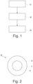
- Figure 1 illustrates schematically and exemplarily an embodiment of a method for manufacturing a biocompatible wire.
- the method for manufacturing a biocompatible wire includes the steps of:
- a cold work percentage is 97 to 99 %
- the cold working is a drawing with a die reduction per pass ratio in a range of 6 to 40 %
- the annealing is done in a range of 850 to 1100°C.
- the drawing is a full die drawing.
- the drawing is done with a deformation factor in a range of 1.2 to 2.0 and a contact length between the workpiece and a drawing tool in a range of 0.5 to 0.2 mm.
- the drawing is done with a speed in a range of 15 to 150 m/min.
- An initial diameter before drawing is in a range of 3 to 5 mm and/or a diameter of the wire after drawing is in a range of 0.1 to 0.9 mm.
- the annealing is done for 750 to 1500 seconds.
- the method for manufacturing a biocompatible wire may further include an additional drawing after the annealing with a cold working percentage of 95 to 97 %.
- the biocompatible wire can be made of or include biocompatible metallic materials and alloys, as for example MP35N and MP35NLT (35%Co-20%Cr-35%Ni-10%Mo with low titanium).
- FIG 2 illustrates schematically and exemplarily an embodiment of a biocompatible wire 10 comprising a biocompatible metallic material, which is cold worked from a workpiece and annealed, wherein a cold work percentage is 97 to 99 %.
- the cold working is a drawing with a die reduction per pass ratio in a range of 6 to 40 % and the annealing is done in a range of 850 to 1100°C.
- Figure 2 further illustrates a medical device 20 comprising such biocompatible wire 10 as a lead.
- the biocompatible metallic material is an alloy comprising the following components: Cr in the range from about 10 to about 30 wt. %; Ni in the range from about 20 to about 50 wt. %; Mo in the range from about 2 to about 20 wt. %; Co in the range from about 10 to about 50 wt. %.
- the Cr, Ni, Mo and Co components are major constituents of the alloy with at least about 95 wt. % of the alloy being Cr, Ni, Mo and Co.
- the biocompatible metallic material further includes an additional material comprising at least one of a group of Silver, Platinum, Tantalum, Gold, Copper and alloys thereof.
- the wire 10 includes grains with a mean grain size in a range of 20 to 1000 nm.
- the wire 10 has a yield strength in a range of 1300 to 1900 MPa.
- the wire 10 has an ultimate tensile strength in a range of 1700 to 2400 MPa.
- the wire 10 has an essentially uniform grain size distribution along a cross section of the wire.
- the Cr, Ni, Mo and Co alloy may form a core 12 and the additional material may form a shell 11 around the core 12 when the wire is seen in a cross section. Otherwise, the additional material may form a core 12 and the Cr, Ni, Mo and Co alloy may form a shell 11 around the core 12 when the wire 10 is seen in a cross section.
- the SR applied on the material is differed by changing the drawing speed, which changes the applied strain over time.
- the as-drawn wires were deformed in uniaxial tension as per ASTM standard E8, using an Instron 6400 test frame, with a load cell of 500 N and by pneumatic yarn grips.
- the crosshead speed was set at 12.7 mm/min, and the gauge length was maintained at 254 mm for all the samples tested.
- the testing was performed at room temperature, and the samples were tested until fracture.
- the hardness test was performed as per ASTM standard A384-17, and the load was differed from 100 to 150 g based on the diameter of the indented wire.
- the indentation was performed both in the longitudinal and transverse sections of the wire, and the indentation time was around 15-20 seconds for each sample. Five points are intended along both the axis which is equidistant from each other and evenly dispersed along their length.
- Hardness values were recorded in Vickers Hardness Scale (H v ).
- the electrical resistivity of the wires was measured using Burster 2316 resistomat.
- the device accords to the proven 4-wire sensing method or by 4-point probe method which is an electrical impedance measuring technique that uses separate pairs of current-carrying and voltage-sensing electrodes to make more accurate measurements than traditional two-terminal sensing.
- 4-point probe method is an electrical impedance measuring technique that uses separate pairs of current-carrying and voltage-sensing electrodes to make more accurate measurements than traditional two-terminal sensing.
- wire samples of 1m long were cut and clamped between the two connecting ends of the clamping device.
- the wires have been tested at room temperature with the temperature compensation set to 20°C and the resistivity data recorded in units of ohm/m.
- the obtained values are then converted into the conductivity measurements and plotted in SI derived units of Siemens/meter.
- the wire specimens drawn with different drawing practices are subjected to cyclic fatigue tests on a rotary beam fatigue tester (RBFT) as per ASTM standard E2948-16a.
- the tests were conducted on a custom-built fatigue test machine by Heraeus.
- the drawn wires were straightened by a roller straightening machine, to remove the residual curvature known as "cast," in the wire which is a geometrical attribute inherited from the cold wire drawing process. This step needs to be done to minimize the variation in the test data, and it was observed during the fatigue set-up that the wires without straightening would spin out of the chuck and fracture at the chucks leading to erroneous results.
- the straightened wires were cut to the desired length based on the input variables of the chuck distance, wire diameter, young's modulus (E), applied stress and the length of the wire was determined from the respective calculations stated in the standard E2948-16a.
- One end of the wire is clenched to a hollow bush, and the other end of the wire is clamped to a rotating chuck which rotates at a speed of 3000RPM and operates at a frequency of 50Hz.
- the vibration supports are mounted along the curvature of the wire, and the break detection probes are placed along the wire.
- a cyclic counter fixed to the machine records the number of cycles to failure, and for each revolution of the chuck, the wire specimens are subjected to an alternate compression and tension cycles during its course of cyclic loading. The tests were performed at room temperature using air as a medium.
- FDD Full Die Drawing
- HDD Half Die Drawing
- MP35NLT wires drawn with different drawing practices namely the FDD and HDD; by varying the amount of deformation per pass induced on the wire, contributed to a wire with different mechanical and work hardening characteristics in the material.
- the plastic instability and the strain rate sensitivity of the materials also varied significantly with the change of deformation process.
- the wires drawn with the FDD drawing process contributed to a higher strength and ductility in the material when compared to the HDD drawn wires for a similar CW reduction.
- a softening effect in the material was observed in the wires drawn with FDD practice between 75-90% CW, which led to a reduction of material strength and increased ductility after which it increased again. This phenomenon was attributed to the "Inverse Hall Petch Effect".
- the deformation homogeneity was higher for the FDD drawn wires, due to the lowered inhomogeneity factor, because of the uniformity in the grain size and the microstructure gradient across the wire.
- the plastic instability (PI) which determines the load bearing capacity or the resistant to necking was lower in the FDD wire until 75% CW, after which it increased upon increase of reduction to 95%.
- the increase in PI was ascribed to the formation of shear bands in the FDD drawn wire, which led to increased plastic strain localization in the material, due to the exhaustion of the dislocation density with the reduced grain size.
- the lower PI until 75% CW was attributed to the higher twin density, and lower twin spacing seen in the FDD wire, which accorded to a higher strain rate work hardening (SRWH) and strain rate sensitivity (SRS) in the wire, which delayed the onset of necking and enhanced ductility in the wire.
- the Strain Rate Sensitivity (SRS) or m value, of the FDD drawn wire decreased with the increase of SR, due to the reduction in the dislocation-based activities and increased GB shearing and diffusion in the deformed wire.
- the twin spacing increased with the increase of SR for the FDD drawn wire, thus contributing to a lower m.
- the Low Cycle Fatigue (LCF) and High Cycle Fatigue (HCF) performance of the FDD drawn wire was remarkably higher than the HDD drawn wire until 75% CW.
- the enhanced LCF performance for the FDD drawn wire is attributed to the higher ductility in the wire, because of the higher number of coherent twin boundaries (CTB) noticed in the FDD drawn wire; this allowed the dislocation to penetrate and slip through them, thus increasing the endurance limit of the wire.
- CTB coherent twin boundaries
- the FDD drawn wire also had a smaller grain size when compared to the HDD wire, which contributed to increased strength and higher dislocation density in the wire, thus bestowing to an improved HCF performance.
- the post fatigued microstructure of the FDD wire also exhibited a dislocation cell and vein structure with several nanotwins embedded between the grain boundaries (GB) and the dislocation pile-up.
- GB grain boundaries
- There were no striations observed in the FDD drawn wire in both the LCF and HCF wires this is because of the reduced ductility in the wire, due to the formation of shear bands.
- the fractured samples exhibited a brittle cleavage fracture, whereas the HDD wire displayed a dimple striation fracture with a dislocation cell structure with nanotwins embedded at the interface of the GB.
- the starting diameters of the material used for the fatigue characterization was 0.62 mm and 0.141 mm respectively, and the material was prepared in a fully annealed condition.
- Three different samples namely 50%, 75% and 95% CW are manufactured by varying the total area reduction.
- the 0.141 mm annealed wire was drawn to a diameter of 0.101 mm to obtain the 50% CW samples; however, for the 75% and 95% CW samples, the 0.62 mm wire was drawn to a diameter of 0.318 and 0.141 mm respectively.
- Table 1 The detailed description of the drawing process for the wires drawn to different CW reductions is illustrated in Table 1.
- the FDD drawn wires could reach the runout at a stress amplitude 530-760 MPa, and the HDD drawn wires reached runout between 460 to 685 MPa.
- the LCF performance of the HDD drawn wires also improved when compared to the 50% CW conditions, there were multiple specimens which were capable of withstanding 1M cycles, in the stress range of 850 to 970 MPa.
- the FDD drawn wires nearly all the samples could reach 1M cycles, and a few of them could even reach the runout of 30M cycles at such high stress.
- the grain size (GS) of the FDD drawn wire was in the range of 100-500 nm, whereas the HDD wire GS was in the range of 700-1500 nm as in Figures 5a-c .
- the LCF behavior of the FDD drawn wire was also better than the HDD wire, even though the GS is smaller for the FDD drawn wire, as the LCF performance is noticed to be enhanced with coarser grain size.
- N f the average no of cycles to failure
- FIG. 4a-d illustrate the TEM images of the grain size and microstructure of the FDD drawn wire drawn to different CW reductions
- Figures 5a-c illustrates the grain size and the microstructure of the HDD drawn wire.
- the smaller grain size and the higher dislocation and twin density as illustrated in Figures 6a-c and Figures 7a-c contributed to higher strength and ductility in the material when compared to HDD wire as illustrated in Figures 8a-c and Figures 9a-c .
- the grain size linearly decreased with the increase of strain but the amount of decrease of the grain size was higher in the material drawn with FDD drawing process.
- the dislocation and twin density were observed to be higher in the FDD drawn wire than the HDD drawn wire for a similar comparison of the applied strain and the dislocation and twin density increased with the increase of strain.
- the current disclosure describes the impact of the drawing technique on the mechanical properties of the wire like the Ys (Yield Strength) and the UTS (Ultimate Tensile Strength) whereby higher mechanical properties especially the yield strength of the wire was obtained in the FDD drawn wire when compared to the HDD drawn wire when subjected to a similar CW reduction.
- Ys Yield Strength
- UTS User Tltimate Tensile Strength
- the work hardening rate in the FDD drawn samples are relatively higher when compared to the HDD wires.
- the initiation or onsite of twin formation is observed at a lower strain in FDD samples whereas the observation of twins is observed in HDD only at higher strains. So, it can be concluded that the FDD drawing process has a stronger effect in reducing the grain size and contributing to higher deformation twinning in the material, thus contributing to higher work hardening rates and increased strength in the wire.
- the current disclosure also describes the impact of the drawing technique on the hardness distribution and stress inhomogenity across the wire for wires subjected to different CW reduction.
- the ⁇ H gradient decreased with the increase of CW for both the FDD and HDD drawn wires, with the gradient being lower for the FDD wires and higher for the HDD wires.
- Microstructure and grain size analysis was repeated on the deformed samples to understand for the drop in ⁇ H gradient.
- CW the increase of CW to 75% CW
- microstructures of the wires drawn with different techniques appeared highly deformed, but the severity of deformation was higher for the FDD wire.
- the increase of ⁇ H gradient for the 95% FDD wire was marginally higher than the 75% CW wire, but lower than the 50% FDD wire, while the ⁇ H gradient decreased in the HDD wire.
- the IF value for the FDD drawn wire was lower than the HDD drawn wire, until 50% CW, after which the variation minimized.
- the IF values increased from the center of the wire to the surface, but the relative increase was higher in the HDD wires when compared to the FDD drawn wires.
- the curves were very similar to each other and the gradient between the surface and the center for both the drawn wires was minimal with the HDD drawn wire having a slightly higher IF value at the surface, however at 95% CWthe IF value and the hardness gradient of the HDD drawn wires increased again when compared to FDD drawn wires.
- the reason for the variation in the hardness gradient in the wires drawn with different drawing practices are rationalized to the different microstructural and grain size distributions observed in the wires.
- the wires drawn with FDD drawing practice have a homogenous deformation throughout the wire cross section as noticed by the uniform hardness and microstructural gradient observed between the center and the surface of the wire.
- the FDD drawn wires have also higher strength and hardness when compared to the HDD processed wires. This explains as why a higher ⁇ H gradient was observed for the HDD samples, when compared to FDD wires.
- the significant difference in the grain size distribution along with the microstructural gradient observed between the surface and the center of the wire would have contributed to the difference in the strength of the wire, with fine grains contributing to a higher strength and hardness, and coarser grains contributing to lower values.
- the current disclosure also studies the impact of the drawing method on the electrical properties of the wire.
- Electrical conductivity is an important property in the design of lead wires, and it is desirable for the wires build into leads to have a high electrical conductance or low electrical resistance in the order of 5-50 ⁇ .
- the reciprocal of the electrical conductivity is termed as the electrical resistivity ( ⁇ ) and it measures the degree through which the conductor opposes the flow of current per unit length.
- the electrical conductivity of the wire decreased with the increase of CW% and the conductivity of HDD drawn wires are higher than the FDD drawn wires until 70% CW, after which the gap between them lowered. This can be attributed to the variation in the deformation mechanics of the wire drawn with different drawing practices, which lead to different strengthening and different microstructures in the wire.
- the HDD drawn wires had a lower amount of lattice defects (dislocations and twins) in the microstructure when compared to the FDD drawn wires.
- the PI of the FDD wire is lower when compared to the HDD wire at 50% CW reduction, with the ( ⁇ +m) value being 0.462 for FDD wire and 0.314 for HDD drawn wire.
- the higher ( ⁇ +m) in FDD wire can be ascribed to the higher strain hardening ability noticed in the FDD drawn wire when compared to the HDD wire where a ⁇ value of 0.435 was obtained for the FDD drawn wire, whereas the HDD wire had a smaller ⁇ value of 0.303.
- the ( ⁇ +m) value for both the FDD and HDD drawn wire surged with the increase of deformation to 75% CW, with the gain being higher for the HDD wire (60%) than the FDD wire (11%) when compared to the results at 50% CW.
- the FDD drawn wire had a ⁇ of 0.473 and m of 0.044, which led to ( ⁇ +m) value of 0.517, unlike the HDD drawn wire which had a ( ⁇ +m) value of 0.501, with ⁇ and m values being 0.462 and 0.039 respectively.
- SR strain rate
- SRS strain rate sensitivity
- SRWH strain rate work hardening
- MP35NLT Co-35Ni-20Cr-10Mo alloy
- FDD Full Die Drawing
- HDD Half Die Drawing
- SRS Strain Rate Sensitivity
- the stress of the wire increased with the increase of strain rate from 10 -6 s -1 to 10 -2 s -1 in both the FDD and HDD drawn wires, but the relative amount of increase in stress for an amount of strain is higher in the FDD drawn wire when compared to the HDD drawn wire.
- the FDD drawn wire had a strength of 2015 MPa, when subjected to a strain rate of 8.3 ⁇ 10 -6 s -1 and increased to 2100 MPa when the strain rate was incremented to 3.3 ⁇ 10 -2 s - 1, however in the HDD drawn wire, the strength of the wire was only 1870 MPa, at the lower strain rate and increased to 2020 MPa with the elevation in strain rate.
- the FDD drawn wire exhibited a single stage hardening regime, at a lower strain rate of 8.3 ⁇ 10 -6 and displayed a three-stage hardening regime between the strain rates of 8.3 ⁇ 10 -5 s -1 to 3.3 ⁇ 10 -2 s - 1, with the stage II peak increasing with the increase of strain rate.
- the HDD drawn wire the material exhibited a single stage hardening curve up to a strain rate of 1.6 ⁇ 10 -3 s -1 and displayed an abnormal three stage hardening curve at a strain rate of 3.3 ⁇ 10 -2 s -1 .
- the normalized hardening values for the FDD drawn wire are comparatively higher than the HDD drawn wire for a similar strain rate applied. This was attributed to the increased dislocation density, reduced twin thickness, and a reduction in the Grain Boundary (GB) mechanisms such as GB sliding and shearing with the increased SR, due to decreased dislocation cell sizes and reduced pile up the GB.
- the Strain Rate Sensitivity (SRS), or m value of the FDD drawn wire decreased with the increase of SR, due to the reduction in the dislocation-based activities and increased GB shearing and diffusion in the deformed wire.
- the twin spacing increased with the increase of SR for the FDD drawn wire, thus contributing to a lower m.
- the m value linearly decreases with the increase of the strain rate for the FDD drawn wires, however for the HDD wire, the m value increases up to a strain rate of 10 -5 s -1 and then decreases with the increase of strain rate as in FDD samples. It could be seen that the FDD drawn wire had a higher m value when compared to the HDD drawn wire.
- the HDD drawn wire exhibited a different deformation mechanism with varying SR. At an SR of 10 -6 s -1 , the strength and hardening of the material was significantly lower than the samples tested at other SR.
- the fracture morphology of the FDD samples looked different when compared to the HDD samples, with the low SR deformed FDD drawn wires exhibiting a higher fraction of the dimpled area and bigger dimple size and vice-versa.
- the dimpled region between the surface and the center of the wire looked homogeneous in size and shape.
- the fractography observations correlated well with the mechanical results of higher m and increased ductility seen in the FDD wire at a lower SR, which confirms the FDD drawn material to have higher resistant to necking, because of its higher SRS and higher hardening rate than the HDD wire.
- the fractography observation of the low SR samples exhibited smaller dimple size and a reduced fractured area, the fractured area also displayed a combination of shear and ductile mode fracture.
- the dimple size at the surface of the wire was smaller when compared to the center, and the deformation looked inhomogeneous.
- the disclosure also explains that MP35NLT and MP35NLT/Ag wires drawn with different filling ratios in the range of 15-41%, when subjected to a prior CW of 95-96% and drawn to a final diameter and subjected to a final stress relief operation in the range of 800-900°C with a dwell time of 2-3 seconds led to a reduction in the EL% and an improvement in the YS and the UTS of the wire, but the reduction of EL was gradual with time and the properties of the wire needed two weeks for stabilization, with higher stress relief temperature contributing to a higher drop when compared to a lower temperatures as illustrated in Table 3, and also contributing to a higher YS/UTS ratio of >0.9.
- the wires drawn with the FDD drawing process produced a microstructure with coarse grains at the surface of the wire and fine grains at the center as illustrated in Figure 10 with a randomly oriented microstructure.
- Table 2 Mechanical data of the lots drawn with the FDD drawing process and subjected to stress relief.
- wires manufactured by the above process also led to a wire free from the inherent residual cast and lift present in the wire this leading to a straight wire on the spool without any mechanical damages induced by the roller straightening processes.
- These types of wires can be used for wires needed for IV therapy and guiding systems for medical applications with an added advantage of high strength and kink resistance.
Landscapes
- Chemical & Material Sciences (AREA)
- Engineering & Computer Science (AREA)
- Mechanical Engineering (AREA)
- Organic Chemistry (AREA)
- Materials Engineering (AREA)
- Metallurgy (AREA)
- Crystallography & Structural Chemistry (AREA)
- Thermal Sciences (AREA)
- Physics & Mathematics (AREA)
- Health & Medical Sciences (AREA)
- General Health & Medical Sciences (AREA)
- Heart & Thoracic Surgery (AREA)
- Vascular Medicine (AREA)
- Manufacturing & Machinery (AREA)
- Metal Extraction Processes (AREA)
- Materials For Medical Uses (AREA)
Abstract
Description
- The disclosure relates to a method for manufacturing a biocompatible wire, a biocompatible wire comprising a biocompatible metallic material and a medical device comprising such wire.
- There are many conventional methods for manufacturing a biocompatible wire, which can be still improved.
- Hence, there may be a need to provide an improved method for manufacturing a biocompatible wire, which in particular allows to achieve a wire with improved fatigue life.
- The problem of the present disclosure is solved by the subject-matters of the independent claims, wherein further embodiments are incorporated in the dependent claims. It should be noted that the aspects of the disclosure described in the following apply also to the method for manufacturing a biocompatible wire, the biocompatible wire comprising a biocompatible metallic material and the medical device comprising such wire.
- According to the present disclosure, a method for manufacturing a biocompatible wire is presented. The method for manufacturing a biocompatible wire includes the steps of providing a workpiece of a biocompatible metallic material, cold working the workpiece into a wire, and annealing the wire. A cold work percentage is 97 to 99 %. The cold working is a drawing with a die reduction per pass ratio in a range of 6 to 40 %. The annealing is done in a range of 850 to 1100°C.
- The present manufacturing method for a biocompatible wire can be considered as an optimized thermo-mechanical process including drawing and annealing steps to produce an improved biocompatible wire. The wires manufactured by the present manufacturing method can have an improved fatigue life through smaller grain sizes and a specific grain size distribution of the wire material and/or a controlled number of dislocations and twins in the crystal structure of the wire. The wires manufactured by the present manufacturing method can have a higher ductility and a higher ultimate strength.
- The wires manufactured by the present manufacturing method can be used for medical applications and in particular to produce coils, strands and the like for medical applications. The medical applications can be Cardiac Rhythmic Management (CRM), neurostimulation, neuromodulation, Deep Brain Stimulation (DBS) and the like.
- The biocompatible wire can be made of or include biocompatible metallic materials and alloys, as for example MP35N and MP35NLT (35%Co-20%Cr-35%Ni-10%Mo with low titanium). The term "biocompatible" can be understood as a quality of not having toxic or injurious effects on biological systems, an ability of a material to perform with an appropriate host response in a specific application, a comparison of a tissue response produced through a close association of an implanted candidate material to its implant site within a host animal to that tissue response recognized and established as suitable with control materials, refers to the ability of a biomaterial to perform its desired function with respect to a medical therapy, without eliciting any undesirable local or systemic effects in the recipient or beneficiary of that therapy, but generating the most appropriate beneficial cellular or tissue response in that specific situation, and optimizing the clinically relevant performance of that therapy and/or as a capability of a prosthesis implanted in the body to exist in harmony with tissue without causing deleterious changes.
- In an embodiment, the biocompatible metallic material is an alloy comprising the following components: Cr in the range from about 10 to about 30 wt. %; Ni in the range from about 20 to about 50 wt. %; Mo in the range from about 2 to about 20 wt. %; Co in the range from about 10 to about 50 wt. % and optionally less than 0.01 wt. % Ti. In an embodiment, the Cr, Ni, Mo and Co components are major constituents of the alloy with at least about 95 wt. % of the alloy being Cr, Ni, Mo and Co.
- After the first cold working and the first annealing (described above), at least a second cold working and/or a second annealing can follow. There can also be at least an initial cold working and/or an initial annealing before above described first cold working and the first annealing.
- The cold work applied to the material decides the geometrical and the mechanical attributes of the wire, as for example its strength. A last and final cold working step defines a final strength of the wire.
- The annealing allows the wire to soften, which might be particular useful to further process the wire to a smaller diameter if needed. The annealing involves parameters of temperature and time, which can depend upon prior deformation and type of material. In case the wire is made of MP35N or MP35NLT, the annealing can be done in the range of 1000°C to 1100°C. In case the wire is made of an MP35NLT or MP35N alloy cladded with Ag, the annealing can be done below the melting point of silver, which is around 960°C. When reducing a diameter of the wire (e.g. by drawing), a duration of the annealing step can be reduced from, e.g., minutes to seconds. Further, the process can be changed from batch annealing to strand annealing. For strand annealing, the amount of time the wire spends in a furnace for annealing can be in the order of few tenths of a second.
- In an embodiment, the drawing is a full die drawing. The drawing may also be a half die drawing. In an embodiment, the drawing is done with a deformation factor in a range of 1.2 to 2.0 and a contact length between the workpiece and a drawing tool in a range of 0.5 to 0.2 mm. In an embodiment, the drawing is done with a speed in a range of 15 to 150 m/min. In an embodiment, the initial diameter before drawing is in a range of 3 to 5 mm and/or a diameter of the wire after drawing is in a range of 0.1 to 0.9 mm. In an embodiment, the annealing is done for 750 to 1500 seconds. In an embodiment, the method for manufacturing a biocompatible wire further includes an additional drawing after the annealing with a cold working percentage of 95 to 97 %.
- The present disclosure deals with the influence of drawing practices namely Full Die Drawing (FDD) and Half Die Drawing (HDD) on the mechanical and electrical properties, deformation homogeneity, plastic instability, strain rate sensitivity, strain rate hardening and cyclic fatigue behavior of MP35NLT or MP35N wires, drawn to different cold work (CW) reductions. The properties are associated and compared against its microstructure, which has been characterized by FESEM, SEM, EBSD, and TEM.
- The FDD drawing proves involved receding the cross-sectional area of the wire at a reduction per pass ratio of 20-30%, with the die semi-angle (α) of 6-8° and by controlling the Δ (deformation factor) value in the range of 1.2-2.0 and with the L value (i.e. the contact length between the work piece and the die) in the range of 0.5-0.2 mm, when compared with the HDD wire drawing processes which generally involve drawing with a Δ value in the range of 2.5-5.0 and with the L being in the range of 0.15-0.05 mm and at an reduction per pass ratio of 6-10%. The wire is drawn from an initial diameter of 3.7 mm to 0.6mm with a CW of 97-99%, using a single die drawing machine and Poly Crystalline Diamond (PCD) dies. For the MP35N and MP35NLT wires, there was only one intermediate annealing applied after 97-99% CW at a temperature of 1050°C-1100°C using a spool to spool annealing machine for a duration of 900-1000 seconds. The wire was further drawn to a diameter of 0.141 mm with a CW of 95-97% using a slip type multiple drawing machine using natural diamond (ND) dies and with varying drawing methods. The wires were drawn at a speed of 30 m/min to 100 m/min depending upon the diameter of the wire drawn, i.e., slower speeds for drawing big diameter wires and faster speeds for drawing smaller diameters, and the wires are drawn using an oil-based lubricant. The FDD method was completed in a shorter time with the total number of dies used being less than 10, while the HDD technique utilized 32-60 dies to complete the total cold work reduction of 98%.
- According to the present disclosure, also a biocompatible wire comprising a biocompatible metallic material is presented. The biocompatible wire includes a biocompatible metallic material which is cold worked from a workpiece and annealed. A cold work percentage is 97 to 99 %. The cold working is a drawing with a die reduction per pass ratio in a range of 6 to 40 %. The annealing is done in a range of 850 to 1100°C.
- In an embodiment, the biocompatible metallic material is an alloy comprising the following components:
- Cr in the range from about 10 to about 30 wt. %;
- Ni in the range from about 20 to about 50 wt. %;
- Mo in the range from about 2 to about 20 wt. %;
- Co in the range from about 10 to about 50 wt. %.
- In an embodiment, the Cr, Ni, Mo and Co components are major constituents of the alloy with at least about 95 wt. % of the alloy being Cr, Ni, Mo and Co. In an embodiment, the biocompatible metallic material further includes an additional component comprising at least one of a group of Silver, Platinum, Tantalum, Gold, Copper and alloys thereof.
- In an embodiment, the Cr, Ni, Mo and Co alloy forms a core and the additional material forms a shell around the core when the wire is seen in a cross section. In another embodiment, the additional material forms a core and the Cr, Ni, Mo and Co alloy forms a shell around the core when the wire is seen in a cross section.
- In an embodiment, the wire includes grains with a mean grain size in a range of 20 to 1000 nm.
- In an embodiment, the wire has a yield strength in a range of 1300 to 1900 MPa.
- In an embodiment, the wire has an ultimate tensile strength in a range of 1700 to 2400 MPa.
- In an embodiment, the wire has an essentially uniform grain size distribution along a cross section of the wire.
- According to the present disclosure, also a medical device is presented. The medical device includes a wire as described above as a lead. The medical device can be used for Cardiac Rhythmic Management (CRM), neurostimulation, neuromodulation, Deep Brain Stimulation (DBS) and the like.
- It shall be understood that the wire, the device, and the manufacturing method according to the independent claims have similar and/or identical preferred embodiments, in particular, as defined in the dependent claims. It shall be understood further that a preferred embodiment of the disclosure can also be any combination of the dependent claims with the respective independent claim.
- These and other aspects of the present disclosure will become apparent from and be elucidated with reference to the embodiments described hereinafter.
- Exemplary embodiments of the disclosure will be described in the following with reference to the accompanying drawing:
-
Figure 1 illustrates schematically and exemplarily an embodiment of a method for manufacturing a biocompatible wire. -
Figure 2 illustrates schematically and exemplarily an embodiment of a biocompatible wire comprising a biocompatible metallic material. -
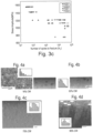
Figure 3a : illustrates schematically and exemplarily an S-N curve comparison between FDD and HDD wires drawn to 50% CW. -
Figure 3b : illustrates schematically and exemplarily an S-N curve comparison between FDD and HDD wires drawn to 75%CW. -
Figure 3c : illustrates schematically and exemplarily an S-N curve comparison between FDD and HDD wires drawn to 95%CW. -
Figures 4a-d : illustrate schematically and exemplarily grain size distributions of the MP35NLT wire drawn with the FDD drawing process for different CW reductions. -
Figures 5a-c : illustrate schematically and exemplarily grain size distributions of the MP35NLT wire drawn with the HDD drawing process for different CW reductions. -
Figures 6a-c : illustrate schematically and exemplarily a dislocation density of the MP35NLT wire drawn with the FDD drawing process for different CW reductions. -
Figures 7a-c : illustrate schematically and exemplarily a dislocation density of the MP35NLT wire drawn with the HDD drawing process for different CW reductions. -
Figures 8a-c : illustrate schematically and exemplarily a twin density of the MP35NLT wire drawn with the FDD drawing process for different CW reductions. -
Figures 9a-c : illustrate schematically and exemplarily a twin density of the MP35NLT wire drawn with the HDD drawing process for different CW reductions. -
Figure 10 : illustrate schematically and exemplarily a wire drawn with the new drawing process and subjected to stress relief temperature of 8750C for a dwell time of 3.1 seconds. - In the following detailed description, reference is made to the accompanying drawings which form a part hereof, and in which is shown by way of illustration specific examples in which the disclosure may be practiced. It is to be understood that other examples may be utilized and structural or logical changes may be made without departing from the scope of the present disclosure. The following detailed description, therefore, is not to be taken in a limiting sense, and the scope of the present disclosure is defined by the appended claims. It is to be understood that features of the various examples described herein may be combined, in part or whole, with each other, unless specifically noted otherwise.
-
Figure 1 illustrates schematically and exemplarily an embodiment of a method for manufacturing a biocompatible wire. The method for manufacturing a biocompatible wire includes the steps of: - S1. providing a workpiece of a biocompatible metallic material,
- S2. cold working the workpiece into a wire, and
- S3. annealing the wire.
- A cold work percentage is 97 to 99 %, the cold working is a drawing with a die reduction per pass ratio in a range of 6 to 40 %, and the annealing is done in a range of 850 to 1100°C.
- The drawing is a full die drawing. The drawing is done with a deformation factor in a range of 1.2 to 2.0 and a contact length between the workpiece and a drawing tool in a range of 0.5 to 0.2 mm. The drawing is done with a speed in a range of 15 to 150 m/min. An initial diameter before drawing is in a range of 3 to 5 mm and/or a diameter of the wire after drawing is in a range of 0.1 to 0.9 mm. The annealing is done for 750 to 1500 seconds. The method for manufacturing a biocompatible wire may further include an additional drawing after the annealing with a cold working percentage of 95 to 97 %.
- The biocompatible wire can be made of or include biocompatible metallic materials and alloys, as for example MP35N and MP35NLT (35%Co-20%Cr-35%Ni-10%Mo with low titanium).
-
Figure 2 illustrates schematically and exemplarily an embodiment of abiocompatible wire 10 comprising a biocompatible metallic material, which is cold worked from a workpiece and annealed, wherein a cold work percentage is 97 to 99 %. The cold working is a drawing with a die reduction per pass ratio in a range of 6 to 40 % and the annealing is done in a range of 850 to 1100°C.Figure 2 further illustrates amedical device 20 comprising suchbiocompatible wire 10 as a lead. - The biocompatible metallic material is an alloy comprising the following components: Cr in the range from about 10 to about 30 wt. %; Ni in the range from about 20 to about 50 wt. %; Mo in the range from about 2 to about 20 wt. %; Co in the range from about 10 to about 50 wt. %. The Cr, Ni, Mo and Co components are major constituents of the alloy with at least about 95 wt. % of the alloy being Cr, Ni, Mo and Co. The biocompatible metallic material further includes an additional material comprising at least one of a group of Silver, Platinum, Tantalum, Gold, Copper and alloys thereof.
- The
wire 10 includes grains with a mean grain size in a range of 20 to 1000 nm. Thewire 10 has a yield strength in a range of 1300 to 1900 MPa. Thewire 10 has an ultimate tensile strength in a range of 1700 to 2400 MPa. Thewire 10 has an essentially uniform grain size distribution along a cross section of the wire. - The Cr, Ni, Mo and Co alloy may form a
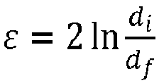
core 12 and the additional material may form ashell 11 around thecore 12 when the wire is seen in a cross section. Otherwise, the additional material may form acore 12 and the Cr, Ni, Mo and Co alloy may form ashell 11 around thecore 12 when thewire 10 is seen in a cross section. - The amount of strain applied in the wire drawing process is defined by the relation;

- The as-drawn wires were deformed in uniaxial tension as per ASTM standard E8, using an Instron 6400 test frame, with a load cell of 500 N and by pneumatic yarn grips. The crosshead speed was set at 12.7 mm/min, and the gauge length was maintained at 254 mm for all the samples tested. The testing was performed at room temperature, and the samples were tested until fracture. The hardness test was performed as per ASTM standard A384-17, and the load was differed from 100 to 150 g based on the diameter of the indented wire. The indentation was performed both in the longitudinal and transverse sections of the wire, and the indentation time was around 15-20 seconds for each sample. Five points are intended along both the axis which is equidistant from each other and evenly dispersed along their length. Hardness values were recorded in Vickers Hardness Scale (Hv).
- The electrical resistivity of the wires was measured using Burster 2316 resistomat. The device accords to the proven 4-wire sensing method or by 4-point probe method which is an electrical impedance measuring technique that uses separate pairs of current-carrying and voltage-sensing electrodes to make more accurate measurements than traditional two-terminal sensing. For each CW% condition, wire samples of 1m long were cut and clamped between the two connecting ends of the clamping device. The wires have been tested at room temperature with the temperature compensation set to 20°C and the resistivity data recorded in units of ohm/m. The obtained values are then converted into the conductivity measurements and plotted in SI derived units of Siemens/meter.
- The wire specimens drawn with different drawing practices are subjected to cyclic fatigue tests on a rotary beam fatigue tester (RBFT) as per ASTM standard E2948-16a. The tests were conducted on a custom-built fatigue test machine by Heraeus. Before the fatigue loading, the drawn wires were straightened by a roller straightening machine, to remove the residual curvature known as "cast," in the wire which is a geometrical attribute inherited from the cold wire drawing process. This step needs to be done to minimize the variation in the test data, and it was observed during the fatigue set-up that the wires without straightening would spin out of the chuck and fracture at the chucks leading to erroneous results. The straightened wires were cut to the desired length based on the input variables of the chuck distance, wire diameter, young's modulus (E), applied stress and the length of the wire was determined from the respective calculations stated in the standard E2948-16a. One end of the wire is clenched to a hollow bush, and the other end of the wire is clamped to a rotating chuck which rotates at a speed of 3000RPM and operates at a frequency of 50Hz. The vibration supports are mounted along the curvature of the wire, and the break detection probes are placed along the wire. A cyclic counter fixed to the machine records the number of cycles to failure, and for each revolution of the chuck, the wire specimens are subjected to an alternate compression and tension cycles during its course of cyclic loading. The tests were performed at room temperature using air as a medium.
- MP35NLT wires drawn with different drawing practices namely the FDD and HDD; by varying the amount of deformation per pass induced on the wire, contributed to a wire with different mechanical and work hardening characteristics in the material. The plastic instability and the strain rate sensitivity of the materials also varied significantly with the change of deformation process. The wires drawn with the FDD drawing process contributed to a higher strength and ductility in the material when compared to the HDD drawn wires for a similar CW reduction. A softening effect in the material was observed in the wires drawn with FDD practice between 75-90% CW, which led to a reduction of material strength and increased ductility after which it increased again. This phenomenon was attributed to the "Inverse Hall Petch Effect". The deformation homogeneity was higher for the FDD drawn wires, due to the lowered inhomogeneity factor, because of the uniformity in the grain size and the microstructure gradient across the wire. The plastic instability (PI), which determines the load bearing capacity or the resistant to necking was lower in the FDD wire until 75% CW, after which it increased upon increase of reduction to 95%. The increase in PI was ascribed to the formation of shear bands in the FDD drawn wire, which led to increased plastic strain localization in the material, due to the exhaustion of the dislocation density with the reduced grain size. The lower PI until 75% CW was attributed to the higher twin density, and lower twin spacing seen in the FDD wire, which accorded to a higher strain rate work hardening (SRWH) and strain rate sensitivity (SRS) in the wire, which delayed the onset of necking and enhanced ductility in the wire. The Strain Rate Sensitivity (SRS) or m value, of the FDD drawn wire decreased with the increase of SR, due to the reduction in the dislocation-based activities and increased GB shearing and diffusion in the deformed wire. The twin spacing increased with the increase of SR for the FDD drawn wire, thus contributing to a lower m. However, with the HDD drawn wire, at an SR of 10-6s-1, the value of m, was 65% lower than the FDD value. The reason for such a low SRS value has been attributed to the increased localized strain concentration in the material, leading to the formation of shear bands in the material which reduces the capability of the material to resist necking and thus reducing the ductility of the material. An abnormal hardening effect was observed in the HDD drawn subjected to an SR of 10-2
s -1, the stage II hardening peak originated at a high strain, instead of its normal commencement at low SR, after the dynamic recovery. This effect was due to the solute segregation of the Mo atoms to the GB, as observed by the increased concentration of the Mo in the deformed structure, which increased the strength and the hardening capacity of the wire. - The Low Cycle Fatigue (LCF) and High Cycle Fatigue (HCF) performance of the FDD drawn wire was remarkably higher than the HDD drawn wire until 75% CW. The enhanced LCF performance for the FDD drawn wire, is attributed to the higher ductility in the wire, because of the higher number of coherent twin boundaries (CTB) noticed in the FDD drawn wire; this allowed the dislocation to penetrate and slip through them, thus increasing the endurance limit of the wire. The FDD drawn wire also had a smaller grain size when compared to the HDD wire, which contributed to increased strength and higher dislocation density in the wire, thus bestowing to an improved HCF performance. The post fatigued microstructure of the FDD wire also exhibited a dislocation cell and vein structure with several nanotwins embedded between the grain boundaries (GB) and the dislocation pile-up. There was a substantial decrease in the LCF and HCF performance of the FDD wires, upon increase of CWto 95%, there were shear bands observed in the microstructure of the FDD drawn wire, which increased the strain localization and a reduced fatigue endurance. There were no striations observed in the FDD drawn wire in both the LCF and HCF wires, this is because of the reduced ductility in the wire, due to the formation of shear bands. The fractured samples exhibited a brittle cleavage fracture, whereas the HDD wire displayed a dimple striation fracture with a dislocation cell structure with nanotwins embedded at the interface of the GB.
- Based on the above observations it can be concluded that the reduction of the grain size to a nanometer scale can be obtained at a lower CW reduction and a higher annealing temperature unlike the prior art. Higher mechanical properties can be obtained in the wire through an optimum control of microstructure and their characteristics such as dislocation density and twin density. The plastic instability studies have given valuable information on the materials response to deformation and their limitations to the applied strain during the drawing process. The strain rate simulation studies which were the first of its kind to be done on this material till date, have led to crucial information in exhibiting the material response when subjected to different speeds during the wire drawing process.
- The influence of drawing practices namely Full Die Drawing (FDD) and Half Die Drawing (HDD) on the cyclic performance of MP35NLT wires have been investigated, by differing the amount of plastic strain applied on the material. The as-drawn wires were subjected to rotary beam fatigue tests (R=-1) with varying stress amplitudes, and the microstructural factors controlling the Low Cycle Fatigue (LCF) and High Cycle Fatigue (HCF) performance were determined through post fatigued TEM investigations. So, the purpose is to characterize the influence of the drawing practices on the cyclic response or fatigue behavior of the MP35NLT wires, drawn to varying cold work (CW) reductions and correlate a link between the process, microstructure, and fatigue.
- Five specimens for each stress amplitude are tested between 500-1500 MPa with a stress ratio of R=-1. Six lots (three from FDD and three from HDD) are tested for the 50% CW condition, and four lots (two from FDD and two from HDD) are tested for the 75 and 95% CW conditions. The runout or the endurance limit for the condition is determined only if all the five samples reach the 30 million (30M) cycles. The post-fatigued specimens are collected and appropriately identified for further microstructure characterization by Transmission Electron Microscope (TEM).
- The starting diameters of the material used for the fatigue characterization was 0.62 mm and 0.141 mm respectively, and the material was prepared in a fully annealed condition. Three different samples namely 50%, 75% and 95% CW are manufactured by varying the total area reduction. The 0.141 mm annealed wire was drawn to a diameter of 0.101 mm to obtain the 50% CW samples; however, for the 75% and 95% CW samples, the 0.62 mm wire was drawn to a diameter of 0.318 and 0.141 mm respectively. The detailed description of the drawing process for the wires drawn to different CW reductions is illustrated in Table 1.

- The cyclic data collected from the Rotary Beam Fatigue Tester (RBFT) tests are plotted in an S-Nf (Wohler) curve as illustrated in
Figure 3 , where the S represents the stress amplitude, and Nf represents the number of cycles to failure. It can be observed fromFigure 3(a) , that the fatigue performance of the 50% CW FDD drawn wires was significantly higher than the HDD wires in both the low cycle fatigue (LCF) and high cycle fatigue (HCF) regimes. The runout (30 million cycles) achieved for a stress amplitude was indicated for the tested batch of wire, with the respective color-coded arrow. It can be noticed that in FDD drawn wires the runout stress amplitude in the HCF region was around 670-780 MPa, whereas the runout stress level for the HDD drawn wire was around 525-585 MPa. The LCF fatigue performance of the FDD drawn wires was also exceptionally higher than the HDD drawn wires with many specimens able to withstand over 1 million (1M) cycles, when tested between 1170-850 MPa stress amplitudes, however for the HDD drawn wires, the wire specimens could reach a fatigue endurance of 1M cycles only at a stress amplitude of 670 MPa. - With the increase of CWto 75% as illustrated in
Figure 3(b) , the performance gap between the two drawn wires reduced, the FDD drawn wires could reach the runout at a stress amplitude 530-760 MPa, and the HDD drawn wires reached runout between 460 to 685 MPa. The LCF performance of the HDD drawn wires also improved when compared to the 50% CW conditions, there were multiple specimens which were capable of withstanding 1M cycles, in the stress range of 850 to 970 MPa. However, with the FDD drawn wires; nearly all the samples could reach 1M cycles, and a few of them could even reach the runout of 30M cycles at such high stress. Further increase of CW to 95%, improved the fatigue behavior of the HDD drawn wires both in the HCF and LCF regions when compared to the FDD drawn wires. The FDD wires reached the runout at a stress level of 1036 MPa whereas the HDD drawn wire could withstand the fatigue life of 30M cycles at a stress amplitude of 1110 MPa. The LCF performance of the HDD drawn wire was also observed to be significantly higher than the FDD drawn wire, with the HDD wires capable of withstanding the 1M cycles at a stress amplitude of 1200 MPa, with an average fatigue life of 16-23M. However, the FDD drawn wire had an average fatigue life of 2.7-9M only. The LCF performance of the HDD wire between the stress amplitude of 1400-1550 MPa was also on an identical note, with the HDD drawn wire outperforming the FDD drawn wire as illustrated inFigure 3(c) . - It is acknowledged that the prior deformation history or the method used to process the material to its finished size, influence the properties of the material. In the current study, by keeping the total area reduction or the total plastic strain constant, the amount of deformation reduction per pass has been differed to study the influence of the drawing method on the cyclic response of the MP35NLT wires. The fatigue performance of the FDD drawn wires were comparatively higher than the HDD drawn wires, in both the LCF and HCF regimes. The LCF and HCF behavior of the materials subjected to cyclic loading is dependent on the properties of the wire such as tensile strength, yield strength, and ductility, which are interrelated to the intrinsic microstructural parameters such as grain size, dislocation density, twin density, and the slip behavior. As seen in
Figures 4a-d , the grain size (GS) of the FDD drawn wire was in the range of 100-500 nm, whereas the HDD wire GS was in the range of 700-1500 nm as inFigures 5a-c . - The smaller GS contributed to the increased strength of the material, where the FDD drawn wire had higher strength than the HDD wire. Since it is well acknowledged that in the HCF region, where the applied stress amplitudes are low, the fatigue behavior of the material is dominated by the crack initiation and most of the time is spent in initiating a crack, rather than propagating a crack which accounts for the total fatigue life. So, with smaller grain size, the residual stress distribution is more homogenous and spread over many grains in the FDD wire, which increased the fatigue resistance in the HCF region.
- The LCF behavior of the FDD drawn wire was also better than the HDD wire, even though the GS is smaller for the FDD drawn wire, as the LCF performance is noticed to be enhanced with coarser grain size. At an applied stress amplitude of 1170MPa, the average no of cycles to failure (Nf) for the three batches of FDD wire were, 3×10⁴, 8×10⁵ and 4×10⁶ cycles; however, it was only 1×10⁴ cycles for all the three batches of HDD wire tested. Even with the decrease of the stress amplitude to 853MPa, which is considered as lower specification of the applied stress amplitude in the LCF region, the no of cycles to failure slightly improved for the HDD drawn wire with the Nf, being 4×10⁴, 4.8×10⁴ and 7×10⁴, and 1×10⁵, 7×10⁵, and 1×10⁶ for the FDD drawn wire.
- Faster reduction of the grain size to a nanometer size and severely deformed structure with high dislocation and twin density was obtained in MP35NLT and MP cladded wires drawn with FDD drawing practice, for a similar CW reduction.
Figures 4a-d illustrate the TEM images of the grain size and microstructure of the FDD drawn wire drawn to different CW reductions andFigures 5a-c illustrates the grain size and the microstructure of the HDD drawn wire. The smaller grain size and the higher dislocation and twin density as illustrated inFigures 6a-c and Figures 7a-c contributed to higher strength and ductility in the material when compared to HDD wire as illustrated inFigures 8a-c andFigures 9a-c . The grain size linearly decreased with the increase of strain but the amount of decrease of the grain size was higher in the material drawn with FDD drawing process. - The dislocation and twin density were observed to be higher in the FDD drawn wire than the HDD drawn wire for a similar comparison of the applied strain and the dislocation and twin density increased with the increase of strain.
- The current disclosure describes the impact of the drawing technique on the mechanical properties of the wire like the Ys (Yield Strength) and the UTS (Ultimate Tensile Strength) whereby higher mechanical properties especially the yield strength of the wire was obtained in the FDD drawn wire when compared to the HDD drawn wire when subjected to a similar CW reduction. A higher work hardening rate and different hardening regimes are obtained with the MP35NLT material subjected to FDD drawing process.
- Based on the above results it can be summarized that the work hardening rate in the FDD drawn samples are relatively higher when compared to the HDD wires. The initiation or onsite of twin formation is observed at a lower strain in FDD samples whereas the observation of twins is observed in HDD only at higher strains. So, it can be concluded that the FDD drawing process has a stronger effect in reducing the grain size and contributing to higher deformation twinning in the material, thus contributing to higher work hardening rates and increased strength in the wire.
- In metal forming processes, such as wire drawing, due to its high plastic deformation, there is a severe contribution of redundant work to the stress flow in the work piece, which makes the distribution of stress and strain to be non-uniform. This leads to a condition known as "Inhomogeneous Deformation" which brings about a heterogeneity in the texture and microstructure of the wires, thus affecting the mechanical and physical properties of the wire.
- In the current work, the influence of the drawing practices on the inhomogeneous deformation was studied, by calculating the Inhomogeneous Factor (IF).
- The current disclosure also describes the impact of the drawing technique on the hardness distribution and stress inhomogenity across the wire for wires subjected to different CW reduction. The hardness values (HV) of the FDD and HDD drawn wires subjected to different CW reductions along Axis-1 (Transverse direction) and Axis-2 (Longitudinal). The hardness values measured across the wire cross section were used to determine the inhomogeneity in the wire, the equation for calculation the inhomogeneity is defined as, IF =

- It was observed that the hardness value at the surface, was higher for the FDD wires when compared to the HDD wire until 50% CW, and the gradient in hardness ΔH (Hardness at the surface-Hardness at the center) was higher for the HDD drawn wires until 75% CW, after which it decreases until 95% CW. For the FDD samples, the hardness gradient for the 50% and 75% CW samples was comparatively lower than the HDD drawn wires. To understand the reason behind the variation in the ΔH gradient between the FDD and HDD samples, EBSD and FESEM analysis were performed on the samples deformed to various CW%. The ΔH gradient decreased with the increase of CW for both the FDD and HDD drawn wires, with the gradient being lower for the FDD wires and higher for the HDD wires. Microstructure and grain size analysis was repeated on the deformed samples to understand for the drop in ΔH gradient. With the increase of CW to 75% CW, microstructures of the wires drawn with different techniques appeared highly deformed, but the severity of deformation was higher for the FDD wire. With further increase of plastic deformation to 95% CW, the increase of ΔH gradient for the 95% FDD wire was marginally higher than the 75% CW wire, but lower than the 50% FDD wire, while the ΔH gradient decreased in the HDD wire. The IF value for the FDD drawn wire was lower than the HDD drawn wire, until 50% CW, after which the variation minimized. The IF values increased from the center of the wire to the surface, but the relative increase was higher in the HDD wires when compared to the FDD drawn wires. At 75% CW the curves were very similar to each other and the gradient between the surface and the center for both the drawn wires was minimal with the HDD drawn wire having a slightly higher IF value at the surface, however at 95% CWthe IF value and the hardness gradient of the HDD drawn wires increased again when compared to FDD drawn wires. The reason for the variation in the hardness gradient in the wires drawn with different drawing practices are rationalized to the different microstructural and grain size distributions observed in the wires.
- Based on the above findings, it can be concluded that the wires drawn with FDD drawing practice have a homogenous deformation throughout the wire cross section as noticed by the uniform hardness and microstructural gradient observed between the center and the surface of the wire. The FDD drawn wires have also higher strength and hardness when compared to the HDD processed wires. This explains as why a higher ΔH gradient was observed for the HDD samples, when compared to FDD wires. The significant difference in the grain size distribution along with the microstructural gradient observed between the surface and the center of the wire, would have contributed to the difference in the strength of the wire, with fine grains contributing to a higher strength and hardness, and coarser grains contributing to lower values. This corresponds well with the Hall- Petch relationship, on the increase of strength in the material with a decreased grain size. Smaller microstructural gradient was observed for the FDD wires between the center and the surface of the wires, thus contributing to a smaller ΔH gradient. The higher IF value imply an existence of higher redundant work in the work piece with increased level of non-homogenous deformation. However, for the FDD wires the deformation and stress distribution between the surface and the center of the wire surface was uniform which contributed to uniform microstructure and hardness gradient and lower IF values and thus homogenous deformation.
- The current disclosure also studies the impact of the drawing method on the electrical properties of the wire. Electrical conductivity is an important property in the design of lead wires, and it is desirable for the wires build into leads to have a high electrical conductance or low electrical resistance in the order of 5-50Ω. The reciprocal of the electrical conductivity is termed as the electrical resistivity (ρ) and it measures the degree through which the conductor opposes the flow of current per unit length.
- The electrical conductivity of the wire decreased with the increase of CW% and the conductivity of HDD drawn wires are higher than the FDD drawn wires until 70% CW, after which the gap between them lowered. This can be attributed to the variation in the deformation mechanics of the wire drawn with different drawing practices, which lead to different strengthening and different microstructures in the wire. The HDD drawn wires had a lower amount of lattice defects (dislocations and twins) in the microstructure when compared to the FDD drawn wires.
- This explains why the HDD drawn wire had a higher electrical conductivity when compared to the FDD drawn wire. The results concluded that increased strength in the material by the generation of defects in the wire leads to a loss of electrical conductivity in the wire, due to the increased scattering of the conductive electrons, which results in a decreased electron mean free path and increased reflective coefficient.
- Metals when plastically deformed by traditional forming methods such as rolling, forging, extrusion, wire drawing, significantly improved the strength of the material, however, the exceptional increase in strength has been compensated by the loss of ductility in many materials. This has been attributed to the flow localization in the material, which contributed to an expedited necking in the material during its tensile deformation in monotonic test conditions. This localized phenomenon of strain localization causes the deformation inhomogeneous driving to a phenomenon called plastic instability (PI). It is considered being a trade-off between the strain hardening (γ) and the strain rate sensitivity (m) of the material which resists or delays the necking in the material when subjected to a uniaxial tensile deformation. So, the control of plastic instability in the material is very important from an engineering standpoint of view, especially when the grain size is reduced to nanoscale for the desired strength improvements On the onset of the plastic instability, the material loses its load bearing capacity, and the stress continues to decrease with the increase of strain, leading to a catastrophic fracture. The PI in the materials is defined by the equation;


- The PI of the FDD wire is lower when compared to the HDD wire at 50% CW reduction, with the (γ+m) value being 0.462 for FDD wire and 0.314 for HDD drawn wire. The higher (γ+m) in FDD wire can be ascribed to the higher strain hardening ability noticed in the FDD drawn wire when compared to the HDD wire where a γ value of 0.435 was obtained for the FDD drawn wire, whereas the HDD wire had a smaller γ value of 0.303. The results corresponded well to the higher strain rate sensitivity values (m) observed in the FDD drawn wire when compared to the HDD drawn wire (m=0.027 for FDD and m=0.011 for HDD). By increasing the total area reduction to 75%, the (γ+m) value for both the FDD and HDD drawn wire surged with the increase of deformation to 75% CW, with the gain being higher for the HDD wire (60%) than the FDD wire (11%) when compared to the results at 50% CW. The FDD drawn wire had a γ of 0.473 and m of 0.044, which led to (γ+m) value of 0.517, unlike the HDD drawn wire which had a (γ+m) value of 0.501, with γ and m values being 0.462 and 0.039 respectively. On further increase of CW reduction to 95% it can be observed that the (γ+m) value of the FDD drawn wire decreased significantly from a value of 0.517 at 75% CW to 0.295. However, for the HDD drawn wire, the decline in the (γ+m) value was lower from a value of 0.501 to 0.393.
- The effect of strain rate (SR) on the strain rate sensitivity (SRS), strain rate work hardening (SRWH) in Co-35Ni-20Cr-10Mo alloy (MP35NLT) wires, subjected to drawing practices namely Full Die Drawing (FDD) and Half Die Drawing (HDD) is analyzed and reported. The deformation resistance or the fracture mechanics in the material subjected to plastic deformation are determined by its grain size, the applied strain rate and its processing temperature. As the strain rate determines the loading sensitivity of the material over time, the understanding of the plastic behavior of the metal when subjected to different strain rates is of great importance for ensuring the dependability and endurance of the material, during its service. The influence of the strain rate on the plastic deformation of the metals is determined by a parameter called Strain Rate Sensitivity (SRS) which is defined by

- The stress of the wire increased with the increase of strain rate from 10-6s-1 to 10-2s-1 in both the FDD and HDD drawn wires, but the relative amount of increase in stress for an amount of strain is higher in the FDD drawn wire when compared to the HDD drawn wire. The FDD drawn wire had a strength of 2015 MPa, when subjected to a strain rate of 8.3 × 10⁻⁶s-1 and increased to 2100 MPa when the strain rate was incremented to 3.3 × 10⁻²
s -1, however in the HDD drawn wire, the strength of the wire was only 1870 MPa, at the lower strain rate and increased to 2020 MPa with the elevation in strain rate. There was a significant difference observed in the hardening behavior of the FDD and HDD drawn wire, for the applied strain rate. The FDD drawn wire exhibited a single stage hardening regime, at a lower strain rate of 8.3×10⁻⁶ and displayed a three-stage hardening regime between the strain rates of 8.3×10⁻⁵s-1 to 3.3×10⁻²s -1, with the stage II peak increasing with the increase of strain rate. However, in the HDD drawn wire the material exhibited a single stage hardening curve up to a strain rate of 1.6×10⁻³s-1 and displayed an abnormal three stage hardening curve at a strain rate of 3.3×10⁻²s-1. It was also noticed that the normalized hardening values for the FDD drawn wire are comparatively higher than the HDD drawn wire for a similar strain rate applied. This was attributed to the increased dislocation density, reduced twin thickness, and a reduction in the Grain Boundary (GB) mechanisms such as GB sliding and shearing with the increased SR, due to decreased dislocation cell sizes and reduced pile up the GB. The Strain Rate Sensitivity (SRS), or m value of the FDD drawn wire decreased with the increase of SR, due to the reduction in the dislocation-based activities and increased GB shearing and diffusion in the deformed wire. The twin spacing increased with the increase of SR for the FDD drawn wire, thus contributing to a lower m. The m value linearly decreases with the increase of the strain rate for the FDD drawn wires, however for the HDD wire, the m value increases up to a strain rate of 10-5 s-1 and then decreases with the increase of strain rate as in FDD samples. It could be seen that the FDD drawn wire had a higher m value when compared to the HDD drawn wire. The HDD drawn wire exhibited a different deformation mechanism with varying SR. At an SR of 10-6s-1, the strength and hardening of the material was significantly lower than the samples tested at other SR. TEM investigations, confirmed that in the low SR deformed sample, due to the absence of prior dislocations in the microstructure, the dislocation conciliated plastic deformation activities were absent in the material, which made the deformation intergranular due to the enhanced GB activities such as GB sliding. This limited the ability of the material to resist the large strains and thus promoting an extremely localized deformation, resulting in the formation of shear bands in the microstructure which made the deformation highly inhomogeneous and contributing to severe plastic instability in the material. This reduced the work hardening and load-bearing capacity of the material thus contributing to lower strength, ductility and a reduced SRS. An abnormal hardening effect was observed in the HDD drawn subjected to an SR of 10-2s -1, the stage II hardening peak originated at a very high strain, instead of its normal commencement at low SR, after the dynamic recovery. This effect was accredited to the solute segregation of the Mo atoms to the GB, as observed by the increased concentration of the Mo concentration in the deformed structure, which increased the strength and the hardening capacity of the wire. - The fracture morphology of the FDD samples looked different when compared to the HDD samples, with the low SR deformed FDD drawn wires exhibiting a higher fraction of the dimpled area and bigger dimple size and vice-versa. The dimpled region between the surface and the center of the wire looked homogeneous in size and shape. The fractography observations correlated well with the mechanical results of higher m and increased ductility seen in the FDD wire at a lower SR, which confirms the FDD drawn material to have higher resistant to necking, because of its higher SRS and higher hardening rate than the HDD wire.
- However, with the HDD drawn wire, the fractography observation of the low SR samples exhibited smaller dimple size and a reduced fractured area, the fractured area also displayed a combination of shear and ductile mode fracture. The dimple size at the surface of the wire was smaller when compared to the center, and the deformation looked inhomogeneous.
- The disclosure also explains that MP35NLT and MP35NLT/Ag wires drawn with different filling ratios in the range of 15-41%, when subjected to a prior CW of 95-96% and drawn to a final diameter and subjected to a final stress relief operation in the range of 800-900°C with a dwell time of 2-3 seconds led to a reduction in the EL% and an improvement in the YS and the UTS of the wire, but the reduction of EL was gradual with time and the properties of the wire needed two weeks for stabilization, with higher stress relief temperature contributing to a higher drop when compared to a lower temperatures as illustrated in Table 3, and also contributing to a higher YS/UTS ratio of >0.9.
- The wires drawn with the FDD drawing process produced a microstructure with coarse grains at the surface of the wire and fine grains at the center as illustrated in
Figure 10 with a randomly oriented microstructure. - Table 2: Mechanical data of the lots drawn with the FDD drawing process and subjected to stress relief.


- The wires manufactured by the above process also led to a wire free from the inherent residual cast and lift present in the wire this leading to a straight wire on the spool without any mechanical damages induced by the roller straightening processes. These types of wires can be used for wires needed for IV therapy and guiding systems for medical applications with an added advantage of high strength and kink resistance.
- It has to be noted that embodiments of the disclosure are described with reference to different subject matters. In particular, some embodiments are described with reference to method type claims whereas other embodiments are described with reference to the device type claims. However, a person skilled in the art will gather from the above and the following description that, unless otherwise notified, in addition to any combination of features belonging to one type of subject matter also any combination between features relating to different subject matters is considered to be disclosed with this application. However, all features can be combined providing synergetic effects that are more than the simple summation of the features.
- While the disclosure has been illustrated and described in detail in the drawings and foregoing description, such illustration and description are to be considered illustrative or exemplary and not restrictive. The disclosure is not limited to the disclosed embodiments. Other variations to the disclosed embodiments can be understood and effected by those skilled in the art in practicing a claimed disclosure, from a study of the drawings, the disclosure, and the dependent claims.
- In the claims, the word "comprising" does not exclude other elements or steps, and the indefinite article "a" or "an" does not exclude a plurality. A single unit may fulfil the functions of several items re-cited in the claims. The mere fact that certain measures are re-cited in mutually different dependent claims does not indicate that a combination of these measures cannot be used to advantage.
- Although specific examples have been illustrated and described herein, a variety of alternate and/or equivalent implementations may be substituted for the specific examples shown and described without departing from the scope of the present disclosure. This application is intended to cover any adaptations or variations of the specific examples discussed herein. Therefore, it is intended that this disclosure be limited only by the claims and the equivalents thereof.
- In view of the above, further aspects and embodiments of the present invention relate to:
- 1. A method for manufacturing a biocompatible wire, comprising: providing a workpiece of a biocompatible metallic material; cold working the workpiece into a wire; and annealing the wire; wherein a cold work percentage is 97 to 99 %; wherein the cold working is a drawing with a die reduction per pass ratio in a range of 6 to 40 %; and wherein the annealing is done in a range of 850 to 1100°C.
- 2. The method according to
aspect 1, wherein the drawing is a full die drawing. - 3. The method according to
aspect 1, wherein the drawing is done with a deformation factor in a range of 1.2 to 2.0 and a contact length between the workpiece and a drawing tool in a range of 0.5 to 0.2 mm. - 4. The method according to
aspect 1, wherein the drawing is done with a speed in a range of 15 to 150 m/min. - 5. The method according to
aspect 1, wherein an initial diameter before drawing is in a range of 3 to 5 mm and/or a diameter of the wire after drawing is in a range of 0.1 to 0.9 mm. - 6. The method according to
aspect 1, wherein the annealing is done for 750 to 1500 seconds. - 7. The method according to
aspect 1, further comprising an additional drawing after the annealing with a cold working percentage of 95 to 97 %. - 8. A biocompatible wire comprising a biocompatible metallic material, which is cold worked from a workpiece and annealed, wherein a cold work percentage is 97 to 99 %, wherein the cold working is a drawing with a die reduction per pass ratio in a range of 6 to 40 %, and wherein the annealing is done in a range of 850 to 1100°C.
- 9. The wire according to aspect 8, wherein the wire comprises grains with a mean grain size in a range of 20 to 1000 nm.
- 10. The wire according to aspect 8, wherein the wire has a yield strength in a range of 1300 to 1900 MPa.
- 11. The wire according to aspect 8, wherein the wire has an ultimate tensile strength in a range of 1700 to 2400 MPa.
- 12. The wire according to aspect 8, wherein the wire has an essentially uniform grain size distribution along a cross section of the wire.
- 13. The wire according to aspect 8, wherein the biocompatible metallic material is an alloy comprising the following components: Cr in the range from about 10 to about 30 wt. %; Ni in the range from about 20 to about 50 wt. %; Mo in the range from about 2 to about 20 wt. %; Co in the range from about 10 to about 50 wt. %, wherein the Cr, Ni, Mo and Co components are major constituents of the alloy with at least about 95 wt. % of the alloy being Cr, Ni, Mo and Co.
- 14. The wire according to aspect 13, wherein the biocompatible metallic material further comprises an additional material comprising at least one of a group of Silver, Platinum, Tantalum, Gold, Copper and alloys thereof.
- 15. The wire according to aspect 14, wherein the Cr, Ni, Mo and Co alloy forms a core and the additional material forms a shell around the core when the wire is seen in a cross section.
- 16. The wire according to aspect 14, wherein the additional material forms a core and the Cr, Ni, Mo and Co alloy forms a shell around the core when the wire is seen in a cross section.
- 17. A medical device, comprising a wire according to aspect 8, as a lead.
- Without limiting the foregoing description, further non-limiting aspects of the present disclosure, numbered 1b-15b, are provided below:
- 1b. A method for manufacturing a biocompatible wire, comprising the steps of:
- providing a workpiece of a biocompatible metallic material,
- cold working the workpiece into a wire, and
- annealing the wire,
- 2b. Method according to aspect 1b, wherein the drawing is a full die drawing.
- 3b. Method according to aspect 1b, wherein the drawing is done with a deformation factor in a range of 1.2 to 2.0 and a contact length between the workpiece and a drawing tool in a range of 0.5 to 0.2 mm.
- 4b. Method according to aspect 1b, wherein the drawing is done with a speed in a range of 15 to 150 m/min.
- 5b. Method according to aspect 1b, wherein an initial diameter before drawing is in a range of 3 to 5 mm and/or a diameter of the wire after drawing is in a range of 0.1 to 0.9 mm.
- 6b. Method according to aspect 1b, wherein the annealing is done for 750 to 1500 seconds. 7b. Method according to aspect 1b, further comprising an additional drawing after the annealing with a cold working percentage of 95 to 97 %.
- 8b. A biocompatible wire comprising a biocompatible metallic material, which is cold worked from a workpiece and annealed, wherein a cold work percentage is 97 to 99 %, wherein the cold working is a drawing with a die reduction per pass ratio in a range of 6 to 40 %, and wherein the annealing is done in a range of 850 to 1100°C.
- 9b. Wire according to aspect 8b, wherein the wire comprises grains with a mean grain size in a range of 20 to 1000 nm.
- 10b. Wire according to aspect 8b, wherein the wire has a yield strength in a range of 1300 to 1900 MPa, or wherein the wire has an ultimate tensile strength in a range of 1700 to 2400 MPa.
- 11b. Wire according to aspect 8b, wherein the wire has an essentially uniform grain size distribution along a cross section of the wire.
- 12b. Wire according to aspect 8b, wherein the biocompatible metallic material is an alloy comprising the following components:
- Cr in the range from about 10 to about 30 wt. %;
- Ni in the range from about 20 to about 50 wt. %;
- Mo in the range from about 2 to about 20 wt. %;
- Co in the range from about 10 to about 50 wt. %,
- 13b. Wire according to aspect 12b, wherein the biocompatible metallic material further comprises an additional material comprising at least one of a group of Silver, Platinum, Tantalum, Gold, Copper and alloys thereof.
- 14b. Wire according to aspect 13b, wherein the Cr, Ni, Mo and Co alloy forms a core and the additional material forms a shell around the core when the wire is seen in a cross section, or wherein the additional material forms a core and the Cr, Ni, Mo and Co alloy forms a shell around the core when the wire is seen in a cross section.
- 15b. A medical device, comprising a wire according to any one of aspects 8b to 14b, as a lead.
Claims (15)
- A biocompatible wire comprising a biocompatible metallic material, which is cold worked from a workpiece and annealed,wherein a cold work percentage is 97 to 99 %,wherein the cold working is a drawing with a die reduction per pass ratio in a range of 6 to 40 %, andwherein the annealing is done in a range of 850 to 1100°C, andwherein the wire comprises grains with a mean grain size in a range of 20 to 1000 nm.
- The wire according to claim 1, wherein the wire has a yield strength in a range of 1300 to 1900 MPa.
- The wire according to claim 1, wherein the wire has an ultimate tensile strength in a range of 1700 to 2400 MPa.
- The wire according to claim 1, wherein the wire has an essentially uniform grain size distribution along a cross section of the wire.
- The wire according to claim 1, wherein the biocompatible metallic material is an alloy comprising the following components:- Cr in the range from about 10 to about 30 wt. %;- Ni in the range from about 20 to about 50 wt. %;- Mo in the range from about 2 to about 20 wt. %;- Co in the range from about 10 to about 50 wt. %.
- The wire according to claim 5, wherein the Cr, Ni, Mo and Co components are major constituents of the alloy with at least about 95 wt. % of the alloy being Cr, Ni, Mo and Co.
- The wire according to claim 5, wherein the biocompatible metallic material further comprises an additional material comprising at least one of a group of Silver, Platinum, Tantalum, Gold, Copper and alloys thereof.
- The wire according to claim 7, wherein the Cr, Ni, Mo and Co alloy forms a core and the additional material forms a shell around the core when the wire is seen in a cross section.
- The wire according to claim 7, wherein the additional material forms a core and the Cr, Ni, Mo and Co alloy forms a shell around the core when the wire is seen in a cross section.
- The wire according to claim 1, wherein the drawing is a full die drawing.
- The wire according to claim 1, wherein the drawing is done with a deformation factor in a range of 1.2 to 2.0 and a contact length between the workpiece and a drawing tool in a range of 0.5 to 0.2 mm.
- The wire according to claim 1, wherein the drawing is done with a speed in a range of 15 to 150 m/min, and/or wherein the annealing is done for 750 to 1500 seconds.
- The wire according to claim 1, wherein a diameter of the wire after drawing is in a range of 0.1 to 0.9 mm.
- The wire according to claim 1, wherein the annealing is followed by an additional drawing with a cold working percentage of 95 to 97 %.
- A medical device, comprising a wire according to any one of claims 1 to 14, as a lead.
Applications Claiming Priority (2)
| Application Number | Priority Date | Filing Date | Title |
|---|---|---|---|
| US16/749,495 US11697869B2 (en) | 2020-01-22 | 2020-01-22 | Method for manufacturing a biocompatible wire |
| EP21152555.5A EP3854495B1 (en) | 2020-01-22 | 2021-01-20 | Method for manufacturing a biocompatible wire |
Related Parent Applications (1)
| Application Number | Title | Priority Date | Filing Date |
|---|---|---|---|
| EP21152555.5A Division EP3854495B1 (en) | 2020-01-22 | 2021-01-20 | Method for manufacturing a biocompatible wire |
Publications (2)
| Publication Number | Publication Date |
|---|---|
| EP4242333A2 true EP4242333A2 (en) | 2023-09-13 |
| EP4242333A3 EP4242333A3 (en) | 2023-11-22 |
Family
ID=74194574
Family Applications (2)
| Application Number | Title | Priority Date | Filing Date |
|---|---|---|---|
| EP23182395.6A Withdrawn EP4242333A3 (en) | 2020-01-22 | 2021-01-20 | Method for manufacturing a biocompatible wire |
| EP21152555.5A Active EP3854495B1 (en) | 2020-01-22 | 2021-01-20 | Method for manufacturing a biocompatible wire |
Family Applications After (1)
| Application Number | Title | Priority Date | Filing Date |
|---|---|---|---|
| EP21152555.5A Active EP3854495B1 (en) | 2020-01-22 | 2021-01-20 | Method for manufacturing a biocompatible wire |
Country Status (2)
| Country | Link |
|---|---|
| US (2) | US11697869B2 (en) |
| EP (2) | EP4242333A3 (en) |
Families Citing this family (2)
| Publication number | Priority date | Publication date | Assignee | Title |
|---|---|---|---|---|
| CN116043065B (en) * | 2021-10-28 | 2024-04-30 | 湖北振华化学股份有限公司 | Corrosion-resistant nano twin crystal nickel-based alloy and preparation method and application thereof |
| CN119733750B (en) * | 2024-12-27 | 2025-10-24 | 中国科学院金属研究所 | A method for preparing high-strength cobalt-based alloy wire |
Family Cites Families (88)
| Publication number | Priority date | Publication date | Assignee | Title |
|---|---|---|---|---|
| US2525130A (en) | 1944-03-10 | 1950-10-10 | Rolls Royce | Aluminium alloy having low coefficient of expansion |
| US2743175A (en) | 1953-01-27 | 1956-04-24 | Int Nickel Co | Precision casting alloy |
| US3356542A (en) | 1967-04-10 | 1967-12-05 | Du Pont | Cobalt-nickel base alloys containing chromium and molybdenum |
| US3711385A (en) | 1970-09-25 | 1973-01-16 | Chemnor Corp | Electrode having platinum metal oxide coating thereon,and method of use thereof |
| US4048045A (en) | 1974-12-19 | 1977-09-13 | Hooker Chemicals & Plastics Corporation | Lengthening anode life in electrolytic cell having molded body |
| US4487744A (en) | 1982-07-28 | 1984-12-11 | Carpenter Technology Corporation | Corrosion resistant austenitic alloy |
| US4652315A (en) | 1983-06-20 | 1987-03-24 | Sumitomo Metal Industries, Ltd. | Precipitation-hardening nickel-base alloy and method of producing same |
| US4655900A (en) | 1986-03-10 | 1987-04-07 | Beckman Industrial Corporation | Method for treating electrodes and improved electrochemical cell |
| DE3774385D1 (en) | 1986-08-29 | 1991-12-12 | Agency Ind Science Techn | LEAD-OXIDE COATED ELECTRODE FOR ELECTROLYSIS AND THEIR PRODUCTION METHOD. |
| JPS63266045A (en) | 1987-04-24 | 1988-11-02 | Nippon Steel Corp | High al austenitic heat resistant steel having excellent hot workability |
| US5019184A (en) | 1989-04-14 | 1991-05-28 | Inco Alloys International, Inc. | Corrosion-resistant nickel-chromium-molybdenum alloys |
| US5096667A (en) | 1989-11-24 | 1992-03-17 | Energy Conversion Devices, Inc. | Catalytic hydrogen storage electrode materials for use in electrochemical cells and electrochemical cells incorporating the materials |
| US5104607A (en) | 1989-12-07 | 1992-04-14 | Azrak-Hamway International, Inc. | Air cushion table game and method of making same |
| AU627965B2 (en) | 1989-12-15 | 1992-09-03 | Inco Alloys International Inc. | Oxidation resistant low expansion superalloys |
| US5238756A (en) | 1990-04-26 | 1993-08-24 | Ovonic Battery Company | Electrode alloy having decreased hydrogen overpressure and/or low self-discharge |
| US5077006A (en) | 1990-07-23 | 1991-12-31 | Carondelet Foundry Company | Heat resistant alloys |
| DE69106372T2 (en) | 1990-08-21 | 1995-07-13 | Crs Holdings, Inc., Wilmington, Del. | ALLOY WITH LOW THERMAL EXPANSION COEFFICIENT AND ITEM PRODUCED FROM IT. |
| JP3212327B2 (en) | 1991-08-30 | 2001-09-25 | ペルメレック電極株式会社 | Electrode for electrolysis |
| US5318572A (en) | 1992-06-02 | 1994-06-07 | Siemens Pacesetter, Inc. | High efficiency tissue stimulating and signal sensing electrode |
| US5476555A (en) | 1992-08-31 | 1995-12-19 | Sps Technologies, Inc. | Nickel-cobalt based alloys |
| US5439640A (en) | 1993-09-03 | 1995-08-08 | Inco Alloys International, Inc. | Controlled thermal expansion superalloy |
| ATE165120T1 (en) | 1992-09-18 | 1998-05-15 | Inco Alloys Int | SUPER ALLOY WITH LOW EXPANSION COEFFICIENT |
| US5630840A (en) | 1993-01-19 | 1997-05-20 | Schneider (Usa) Inc | Clad composite stent |
| US5405522A (en) | 1994-03-10 | 1995-04-11 | Mannesmann Aktiengesellschaft | Reference electrode and method of making the same |
| US5939204A (en) | 1995-08-16 | 1999-08-17 | Siemens Aktiengesellschaft | Article for transporting a hot, oxidizing gas |
| US5945067A (en) | 1998-10-23 | 1999-08-31 | Inco Alloys International, Inc. | High strength corrosion resistant alloy |
| JP3952861B2 (en) | 2001-06-19 | 2007-08-01 | 住友金属工業株式会社 | Metal material with metal dusting resistance |
| US7171124B2 (en) | 2001-07-19 | 2007-01-30 | Lucent Technologies Inc. | Wavelength routing and switching mechanism for a photonic transport network |
| US6761777B1 (en) | 2002-01-09 | 2004-07-13 | Roman Radon | High chromium nitrogen bearing castable alloy |
| US6884539B2 (en) | 2002-07-02 | 2005-04-26 | Microcell Corporation | Microcell electrochemical devices and assemblies with corrosion-resistant current collectors, and method of making the same |
| JP2004066316A (en) | 2002-08-08 | 2004-03-04 | Bridgestone Corp | Method for manufacturing steel wire for reinforcing rubber |
| US7015392B1 (en) | 2003-05-28 | 2006-03-21 | Accellent, Inc. | High torsional ductility wire and methods of making the same |
| CN1280445C (en) | 2003-07-17 | 2006-10-18 | 住友金属工业株式会社 | Stainless steel and stainless steel pipe having resistance to carburization and coking |
| US8048369B2 (en) | 2003-09-05 | 2011-11-01 | Ati Properties, Inc. | Cobalt-nickel-chromium-molybdenum alloys with reduced level of titanium nitride inclusions |
| SE527319C2 (en) | 2003-10-02 | 2006-02-07 | Sandvik Intellectual Property | Alloy for high temperature use |
| US7280875B1 (en) | 2004-02-04 | 2007-10-09 | Pacesetter, Inc. | High strength, low resistivity electrode |
| US20060029640A1 (en) | 2004-08-05 | 2006-02-09 | Gilbert Jeremy L | Medical devices with surface modification for regulating cell growth on or near the surface |
| US7305270B1 (en) | 2005-04-21 | 2007-12-04 | Pacesetter, Inc. | Cardiac pacing/sensing lead providing far-field signal rejection |
| JP4828986B2 (en) | 2006-03-30 | 2011-11-30 | 株式会社東芝 | Hydrogen storage alloy, hydrogen storage membrane and hydrogen storage tank |
| JP2008093673A (en) | 2006-10-07 | 2008-04-24 | Kinomoto Shinsen Kk | Wire drawing method for magnesium based alloy |
| US7780798B2 (en) | 2006-10-13 | 2010-08-24 | Boston Scientific Scimed, Inc. | Medical devices including hardened alloys |
| JP2008184643A (en) | 2007-01-29 | 2008-08-14 | Nippon Seisen Co Ltd | Method for manufacturing high-strength ultra-fine flat wire, and high-strength metal ultra-fine flat wire obtained using the manufacturing method |
| KR20100092021A (en) | 2007-11-19 | 2010-08-19 | 헌팅턴 앨로이즈 코오포레이션 | Ultra high strength alloy for severe oil and gas environments and method of preparation |
| US8840735B2 (en) * | 2008-09-19 | 2014-09-23 | Fort Wayne Metals Research Products Corp | Fatigue damage resistant wire and method of production thereof |
| JP4780189B2 (en) | 2008-12-25 | 2011-09-28 | 住友金属工業株式会社 | Austenitic heat-resistant alloy |
| WO2011071054A1 (en) | 2009-12-10 | 2011-06-16 | 住友金属工業株式会社 | Austenitic heat-resistant alloy |
| US9138963B2 (en) | 2009-12-14 | 2015-09-22 | United Technologies Corporation | Low sulfur nickel base substrate alloy and overlay coating system |
| US8479700B2 (en) | 2010-01-05 | 2013-07-09 | L. E. Jones Company | Iron-chromium alloy with improved compressive yield strength and method of making and use thereof |
| EP2384725B1 (en) | 2010-05-06 | 2018-07-04 | Biotronik AG | Biocorrodable implant in which corrosion may be triggered or accelerated after implantation by means of an external stimulus |
| DE102010049781A1 (en) | 2010-10-29 | 2012-05-03 | Thyssenkrupp Vdm Gmbh | Ni-Fe-Cr-Mo alloy |
| US9409008B2 (en) * | 2011-04-22 | 2016-08-09 | Medtronic, Inc. | Cable configurations for a medical device |
| US8340759B2 (en) * | 2011-04-22 | 2012-12-25 | Medtronic, Inc. | Large-pitch coil configurations for a medical device |
| US9284648B2 (en) | 2011-04-27 | 2016-03-15 | Medtronic, Inc. | Process and material solution to reduce metal ion release for implantable medical device application |
| US9243304B2 (en) | 2011-07-01 | 2016-01-26 | Vacuumschmelze Gmbh & Company Kg | Soft magnetic alloy and method for producing a soft magnetic alloy |
| US20130008687A1 (en) | 2011-07-08 | 2013-01-10 | Industrial Technology Research Institute | Conductive film structure capable of resisting moisture and oxygen and electronic apparatus using the same |
| EP4043065A1 (en) | 2011-10-14 | 2022-08-17 | Sorin CRM SAS | Detection/stimulation microprobe implantable in venous, arterial or lymphatic systems |
| US10259726B2 (en) | 2011-12-21 | 2019-04-16 | GLOBAL WATER INVESTMENTS, LLC a Delaware Limited Liability Company | Electrolytic cell with advanced oxidation process and electro catalytic paddle electrode |
| DE102012011162B4 (en) | 2012-06-05 | 2014-05-22 | Outokumpu Vdm Gmbh | Nickel-chromium alloy with good processability, creep resistance and corrosion resistance |
| US9932655B2 (en) | 2012-06-07 | 2018-04-03 | Nippon Steel & Sumitomo Metal Corporation | Ni-based alloy |
| EP2676685A1 (en) | 2012-06-18 | 2013-12-25 | Biotronik AG | Stent composed of an iron alloy |
| KR102081363B1 (en) | 2012-06-26 | 2020-02-25 | 바이오트로닉 아게 | Magnesium-zinc-calcium alloy, method for production thereof, and use thereof |
| EP2864514B1 (en) | 2012-06-26 | 2020-04-29 | Biotronik AG | Implant made from a magnesium alloy, method for the production thereof and use thereof |
| EP2864513B1 (en) | 2012-06-26 | 2022-02-23 | Biotronik AG | Biodegradable implant made from magnesium-aluminum-zinc alloy and method for the production thereof |
| CA2869459C (en) | 2012-06-26 | 2023-01-03 | Biotronik Ag | Magnesium-zinc-calcium alloy, method for production thereof, and use thereof |
| EP2767294B1 (en) | 2013-02-13 | 2018-03-21 | Biotronik AG | Biocorrodible implant with anti-corrosion coating |
| EP2767295B1 (en) | 2013-02-13 | 2015-11-04 | Biotronik AG | Biocorrodible implant with anti-corrosion coating |
| US9687346B2 (en) | 2013-03-14 | 2017-06-27 | Edwards Lifesciences Corporation | Multi-stranded heat set annuloplasty rings |
| WO2014155820A1 (en) | 2013-03-29 | 2014-10-02 | 古河電気工業株式会社 | Aluminum alloy conductor, aluminum alloy stranded wire, sheathed wire, wire harness, and method for manufacturing aluminum alloy conductor |
| WO2014176025A1 (en) | 2013-04-26 | 2014-10-30 | Icon Medical Corp. | Improved metal alloys for medical devices |
| WO2014182691A2 (en) * | 2013-05-06 | 2014-11-13 | Fort Wayne Metals Research Products Corp. | Titanium-niobium-hafnium alloy shape memory wire |
| US10188546B2 (en) | 2013-10-14 | 2019-01-29 | Sebela Vlc Limited | Intrauterine device with controlled copper ion elution |
| CH708834A1 (en) | 2013-11-14 | 2015-05-15 | Qvanteq Ag | Implant with improved surface properties. |
| CH708833A1 (en) | 2013-11-14 | 2015-05-15 | Qvanteq Ag | Implant with improved surface properties. |
| BR112016030273A2 (en) | 2014-06-24 | 2017-08-22 | Icon Medical Corp | MEDICAL DEVICE AND METHOD FOR FORMING SAID DEVICE |
| US9659679B2 (en) | 2014-10-21 | 2017-05-23 | Medtronic, Inc. | Composite filar for implantable medical device |
| US10109855B2 (en) | 2015-02-11 | 2018-10-23 | Basf Corporation | Hydrogen storage alloys |
| US9856544B2 (en) | 2015-02-11 | 2018-01-02 | Basf Corporation | Hydrogen storage alloys |
| US9765416B2 (en) | 2015-06-24 | 2017-09-19 | Ati Properties Llc | Alloy melting and refining method |
| WO2017004483A1 (en) | 2015-07-02 | 2017-01-05 | Mirus Llc | Medical devices with integrated sensors and method of production |
| US10487377B2 (en) * | 2015-12-18 | 2019-11-26 | Heraeus Deutschland GmbH & Co. KG | Cr, Ni, Mo and Co alloy for use in medical devices |
| JP6147382B1 (en) | 2016-03-07 | 2017-06-14 | 田中貴金属工業株式会社 | Embolization coil and method of manufacturing the embolization coil |
| US11111571B2 (en) | 2016-11-14 | 2021-09-07 | Fort Wayne Metals Research Products | Ni-free beta Ti alloys with shape memory and super-elastic properties |
| US10736761B2 (en) | 2017-04-19 | 2020-08-11 | Medtronic Vascular, Inc. | Method of making a medical device using additive manufacturing with a masking plate |
| US11219744B2 (en) | 2017-04-21 | 2022-01-11 | Medtronic Vascular, Inc. | Push wire for endoluminal medical device |
| EP3415651A1 (en) * | 2017-06-14 | 2018-12-19 | Heraeus Deutschland GmbH & Co. KG | A method for manufacturing a passivated product |
| EP3415195A1 (en) * | 2017-06-14 | 2018-12-19 | Heraeus Deutschland GmbH & Co. KG | A method for manufacturing a cable |
| EP3415649B1 (en) * | 2017-06-14 | 2022-08-03 | Heraeus Deutschland GmbH & Co. KG | A composite wire |
| EP3415650A1 (en) * | 2017-06-14 | 2018-12-19 | Heraeus Deutschland GmbH & Co. KG | A method for manufacturing a composite wire |
-
2020
- 2020-01-22 US US16/749,495 patent/US11697869B2/en active Active
-
2021
- 2021-01-20 EP EP23182395.6A patent/EP4242333A3/en not_active Withdrawn
- 2021-01-20 EP EP21152555.5A patent/EP3854495B1/en active Active
-
2023
- 2023-06-23 US US18/213,580 patent/US20230340654A1/en active Pending
Also Published As
| Publication number | Publication date |
|---|---|
| US20230340654A1 (en) | 2023-10-26 |
| EP4242333A3 (en) | 2023-11-22 |
| US11697869B2 (en) | 2023-07-11 |
| US20210230728A1 (en) | 2021-07-29 |
| EP3854495A1 (en) | 2021-07-28 |
| EP3854495B1 (en) | 2023-07-12 |
Similar Documents
| Publication | Publication Date | Title |
|---|---|---|
| CN1867687B (en) | Cobalt nickel chromium molybdenum alloys containing reduced amounts of titanium nitride inclusions | |
| US20230340654A1 (en) | Method for manufacturing a biocompatible wire | |
| EP3042972B1 (en) | Copper alloy wire | |
| Zhu et al. | Effect of ECAP combined cold working on mechanical properties and electrical conductivity of Conform-produced Cu–Mg alloys | |
| US7015392B1 (en) | High torsional ductility wire and methods of making the same | |
| EP3128019B1 (en) | Copper alloy wire material and manufacturing method thereof | |
| CN103080353B (en) | Special Steel Wire and special steel wire rod | |
| EP2832874B1 (en) | Aluminum alloy wire and process for producing same | |
| EP2743366B1 (en) | Compression coil spring and method for producing same | |
| EP2803742B1 (en) | Bolt and method for manufacturing bolt | |
| Gholizadeh et al. | Global understanding of deformation behavior in CoCrFeMnNi high entropy alloy under high-strain torsion deformation at a wide range of elevated temperatures | |
| JP5103107B2 (en) | High elastic alloy | |
| KR20140117568A (en) | High-strength stainless steel wire having excellent heat deformation resistance, high-strength spring, and method for manufacturing same | |
| Kocich et al. | Crossing the limits of electric conductivity of copper by inducing nanotwinning via extreme plastic deformation at cryogenic conditions | |
| CN110573638A (en) | Wire and Spring | |
| US6527883B1 (en) | Steel wire and method of manufacturing the same | |
| Azevedo et al. | Effects of different wire drawing routes on grain boundary character distribution, microtexture, δ-phase precipitation, grain size and room temperature mechanical behavior of alloy 718 | |
| Gvk et al. | Fatigue behavior in Co–Cr–Ni–Mo medical wires drawn with different drawing practices | |
| DE102018130946B4 (en) | METHOD FOR THE PRODUCTION OF SEMI-FINISHED PRODUCTS FROM A NICKEL-BASED ALLOY | |
| JP2001288530A (en) | High strength and high toughness martensitic steel and its production method | |
| Liang et al. | Experimental investigation on anelasticity-controlled cyclic creep behavior in multiscale hybrid-reinforced TiAl alloys | |
| US20180366239A1 (en) | Method for manufacturing a cable | |
| Rahman et al. | Effect of thermal ageing on the tensile properties of hot and cold rolled commercial high conductive metal and its alloy | |
| Gvk | Co-Cr-Ni-Mo wires for medical applications: processing, mechanical, microstructure and fatigue characterization | |
| US20240384383A1 (en) | Process for manufacturing a nickel-based alloy product |
Legal Events
| Date | Code | Title | Description |
|---|---|---|---|
| PUAI | Public reference made under article 153(3) epc to a published international application that has entered the european phase |
Free format text: ORIGINAL CODE: 0009012 |
|
| STAA | Information on the status of an ep patent application or granted ep patent |
Free format text: STATUS: REQUEST FOR EXAMINATION WAS MADE |
|
| 17P | Request for examination filed |
Effective date: 20230629 |
|
| AC | Divisional application: reference to earlier application |
Ref document number: 3854495 Country of ref document: EP Kind code of ref document: P |
|
| AK | Designated contracting states |
Kind code of ref document: A2 Designated state(s): AL AT BE BG CH CY CZ DE DK EE ES FI FR GB GR HR HU IE IS IT LI LT LU LV MC MK MT NL NO PL PT RO RS SE SI SK SM TR |
|
| REG | Reference to a national code |
Ref country code: DE Ref legal event code: R079 Free format text: PREVIOUS MAIN CLASS: C22C0019070000 Ipc: B21C0001000000 |
|
| PUAL | Search report despatched |
Free format text: ORIGINAL CODE: 0009013 |
|
| AK | Designated contracting states |
Kind code of ref document: A3 Designated state(s): AL AT BE BG CH CY CZ DE DK EE ES FI FR GB GR HR HU IE IS IT LI LT LU LV MC MK MT NL NO PL PT RO RS SE SI SK SM TR |
|
| RIC1 | Information provided on ipc code assigned before grant |
Ipc: C22C 19/07 20060101ALI20231013BHEP Ipc: C22C 19/05 20060101ALI20231013BHEP Ipc: B21F 45/00 20060101ALI20231013BHEP Ipc: B21C 9/00 20060101ALI20231013BHEP Ipc: B21C 1/00 20060101AFI20231013BHEP |
|
| RAP1 | Party data changed (applicant data changed or rights of an application transferred) |
Owner name: HERAEUS MEDEVIO GMBH & CO. KG |
|
| RBV | Designated contracting states (corrected) |
Designated state(s): AL AT BE BG CH CY CZ DE DK EE ES FI FR GB GR HR HU IE IS IT LI LT LU LV MC MK MT NL NO PL PT RO RS SE SI SK SM TR |
|
| STAA | Information on the status of an ep patent application or granted ep patent |
Free format text: STATUS: EXAMINATION IS IN PROGRESS |
|
| 17Q | First examination report despatched |
Effective date: 20240917 |
|
| STAA | Information on the status of an ep patent application or granted ep patent |
Free format text: STATUS: THE APPLICATION HAS BEEN WITHDRAWN |
|
| 18W | Application withdrawn |
Effective date: 20250918 |