EP4242194A1 - Ceramic structure with glazing layer - Google Patents
Ceramic structure with glazing layer Download PDFInfo
- Publication number
- EP4242194A1 EP4242194A1 EP21889280.0A EP21889280A EP4242194A1 EP 4242194 A1 EP4242194 A1 EP 4242194A1 EP 21889280 A EP21889280 A EP 21889280A EP 4242194 A1 EP4242194 A1 EP 4242194A1
- Authority
- EP
- European Patent Office
- Prior art keywords
- region
- glaze layer
- base
- ceramic structure
- concentration
- Prior art date
- Legal status (The legal status is an assumption and is not a legal conclusion. Google has not performed a legal analysis and makes no representation as to the accuracy of the status listed.)
- Pending
Links
Images



Classifications
-
- C—CHEMISTRY; METALLURGY
- C04—CEMENTS; CONCRETE; ARTIFICIAL STONE; CERAMICS; REFRACTORIES
- C04B—LIME, MAGNESIA; SLAG; CEMENTS; COMPOSITIONS THEREOF, e.g. MORTARS, CONCRETE OR LIKE BUILDING MATERIALS; ARTIFICIAL STONE; CERAMICS; REFRACTORIES; TREATMENT OF NATURAL STONE
- C04B35/00—Shaped ceramic products characterised by their composition; Ceramics compositions; Processing powders of inorganic compounds preparatory to the manufacturing of ceramic products
- C04B35/01—Shaped ceramic products characterised by their composition; Ceramics compositions; Processing powders of inorganic compounds preparatory to the manufacturing of ceramic products based on oxide ceramics
- C04B35/16—Shaped ceramic products characterised by their composition; Ceramics compositions; Processing powders of inorganic compounds preparatory to the manufacturing of ceramic products based on oxide ceramics based on silicates other than clay
- C04B35/18—Shaped ceramic products characterised by their composition; Ceramics compositions; Processing powders of inorganic compounds preparatory to the manufacturing of ceramic products based on oxide ceramics based on silicates other than clay rich in aluminium oxide
-
- C—CHEMISTRY; METALLURGY
- C03—GLASS; MINERAL OR SLAG WOOL
- C03C—CHEMICAL COMPOSITION OF GLASSES, GLAZES OR VITREOUS ENAMELS; SURFACE TREATMENT OF GLASS; SURFACE TREATMENT OF FIBRES OR FILAMENTS MADE FROM GLASS, MINERALS OR SLAGS; JOINING GLASS TO GLASS OR OTHER MATERIALS
- C03C3/00—Glass compositions
- C03C3/04—Glass compositions containing silica
- C03C3/076—Glass compositions containing silica with 40% to 90% silica, by weight
- C03C3/083—Glass compositions containing silica with 40% to 90% silica, by weight containing aluminium oxide or an iron compound
- C03C3/085—Glass compositions containing silica with 40% to 90% silica, by weight containing aluminium oxide or an iron compound containing an oxide of a divalent metal
- C03C3/087—Glass compositions containing silica with 40% to 90% silica, by weight containing aluminium oxide or an iron compound containing an oxide of a divalent metal containing calcium oxide, e.g. common sheet or container glass
-
- C—CHEMISTRY; METALLURGY
- C03—GLASS; MINERAL OR SLAG WOOL
- C03C—CHEMICAL COMPOSITION OF GLASSES, GLAZES OR VITREOUS ENAMELS; SURFACE TREATMENT OF GLASS; SURFACE TREATMENT OF FIBRES OR FILAMENTS MADE FROM GLASS, MINERALS OR SLAGS; JOINING GLASS TO GLASS OR OTHER MATERIALS
- C03C8/00—Enamels; Glazes; Fusion seal compositions being frit compositions having non-frit additions
- C03C8/02—Frit compositions, i.e. in a powdered or comminuted form
-
- C—CHEMISTRY; METALLURGY
- C04—CEMENTS; CONCRETE; ARTIFICIAL STONE; CERAMICS; REFRACTORIES
- C04B—LIME, MAGNESIA; SLAG; CEMENTS; COMPOSITIONS THEREOF, e.g. MORTARS, CONCRETE OR LIKE BUILDING MATERIALS; ARTIFICIAL STONE; CERAMICS; REFRACTORIES; TREATMENT OF NATURAL STONE
- C04B35/00—Shaped ceramic products characterised by their composition; Ceramics compositions; Processing powders of inorganic compounds preparatory to the manufacturing of ceramic products
- C04B35/01—Shaped ceramic products characterised by their composition; Ceramics compositions; Processing powders of inorganic compounds preparatory to the manufacturing of ceramic products based on oxide ceramics
- C04B35/10—Shaped ceramic products characterised by their composition; Ceramics compositions; Processing powders of inorganic compounds preparatory to the manufacturing of ceramic products based on oxide ceramics based on aluminium oxide
-
- C—CHEMISTRY; METALLURGY
- C04—CEMENTS; CONCRETE; ARTIFICIAL STONE; CERAMICS; REFRACTORIES
- C04B—LIME, MAGNESIA; SLAG; CEMENTS; COMPOSITIONS THEREOF, e.g. MORTARS, CONCRETE OR LIKE BUILDING MATERIALS; ARTIFICIAL STONE; CERAMICS; REFRACTORIES; TREATMENT OF NATURAL STONE
- C04B35/00—Shaped ceramic products characterised by their composition; Ceramics compositions; Processing powders of inorganic compounds preparatory to the manufacturing of ceramic products
- C04B35/01—Shaped ceramic products characterised by their composition; Ceramics compositions; Processing powders of inorganic compounds preparatory to the manufacturing of ceramic products based on oxide ceramics
- C04B35/16—Shaped ceramic products characterised by their composition; Ceramics compositions; Processing powders of inorganic compounds preparatory to the manufacturing of ceramic products based on oxide ceramics based on silicates other than clay
- C04B35/18—Shaped ceramic products characterised by their composition; Ceramics compositions; Processing powders of inorganic compounds preparatory to the manufacturing of ceramic products based on oxide ceramics based on silicates other than clay rich in aluminium oxide
- C04B35/195—Alkaline earth aluminosilicates, e.g. cordierite or anorthite
-
- C—CHEMISTRY; METALLURGY
- C04—CEMENTS; CONCRETE; ARTIFICIAL STONE; CERAMICS; REFRACTORIES
- C04B—LIME, MAGNESIA; SLAG; CEMENTS; COMPOSITIONS THEREOF, e.g. MORTARS, CONCRETE OR LIKE BUILDING MATERIALS; ARTIFICIAL STONE; CERAMICS; REFRACTORIES; TREATMENT OF NATURAL STONE
- C04B35/00—Shaped ceramic products characterised by their composition; Ceramics compositions; Processing powders of inorganic compounds preparatory to the manufacturing of ceramic products
- C04B35/01—Shaped ceramic products characterised by their composition; Ceramics compositions; Processing powders of inorganic compounds preparatory to the manufacturing of ceramic products based on oxide ceramics
- C04B35/16—Shaped ceramic products characterised by their composition; Ceramics compositions; Processing powders of inorganic compounds preparatory to the manufacturing of ceramic products based on oxide ceramics based on silicates other than clay
- C04B35/20—Shaped ceramic products characterised by their composition; Ceramics compositions; Processing powders of inorganic compounds preparatory to the manufacturing of ceramic products based on oxide ceramics based on silicates other than clay rich in magnesium oxide, e.g. forsterite
-
- C—CHEMISTRY; METALLURGY
- C04—CEMENTS; CONCRETE; ARTIFICIAL STONE; CERAMICS; REFRACTORIES
- C04B—LIME, MAGNESIA; SLAG; CEMENTS; COMPOSITIONS THEREOF, e.g. MORTARS, CONCRETE OR LIKE BUILDING MATERIALS; ARTIFICIAL STONE; CERAMICS; REFRACTORIES; TREATMENT OF NATURAL STONE
- C04B35/00—Shaped ceramic products characterised by their composition; Ceramics compositions; Processing powders of inorganic compounds preparatory to the manufacturing of ceramic products
- C04B35/01—Shaped ceramic products characterised by their composition; Ceramics compositions; Processing powders of inorganic compounds preparatory to the manufacturing of ceramic products based on oxide ceramics
- C04B35/48—Shaped ceramic products characterised by their composition; Ceramics compositions; Processing powders of inorganic compounds preparatory to the manufacturing of ceramic products based on oxide ceramics based on zirconium or hafnium oxides, zirconates, zircon or hafnates
-
- C—CHEMISTRY; METALLURGY
- C04—CEMENTS; CONCRETE; ARTIFICIAL STONE; CERAMICS; REFRACTORIES
- C04B—LIME, MAGNESIA; SLAG; CEMENTS; COMPOSITIONS THEREOF, e.g. MORTARS, CONCRETE OR LIKE BUILDING MATERIALS; ARTIFICIAL STONE; CERAMICS; REFRACTORIES; TREATMENT OF NATURAL STONE
- C04B41/00—After-treatment of mortars, concrete, artificial stone or ceramics; Treatment of natural stone
- C04B41/009—After-treatment of mortars, concrete, artificial stone or ceramics; Treatment of natural stone characterised by the material treated
-
- C—CHEMISTRY; METALLURGY
- C04—CEMENTS; CONCRETE; ARTIFICIAL STONE; CERAMICS; REFRACTORIES
- C04B—LIME, MAGNESIA; SLAG; CEMENTS; COMPOSITIONS THEREOF, e.g. MORTARS, CONCRETE OR LIKE BUILDING MATERIALS; ARTIFICIAL STONE; CERAMICS; REFRACTORIES; TREATMENT OF NATURAL STONE
- C04B41/00—After-treatment of mortars, concrete, artificial stone or ceramics; Treatment of natural stone
- C04B41/45—Coating or impregnating, e.g. injection in masonry, partial coating of green or fired ceramics, organic coating compositions for adhering together two concrete elements
- C04B41/50—Coating or impregnating, e.g. injection in masonry, partial coating of green or fired ceramics, organic coating compositions for adhering together two concrete elements with inorganic materials
- C04B41/5022—Coating or impregnating, e.g. injection in masonry, partial coating of green or fired ceramics, organic coating compositions for adhering together two concrete elements with inorganic materials with vitreous materials
-
- C—CHEMISTRY; METALLURGY
- C04—CEMENTS; CONCRETE; ARTIFICIAL STONE; CERAMICS; REFRACTORIES
- C04B—LIME, MAGNESIA; SLAG; CEMENTS; COMPOSITIONS THEREOF, e.g. MORTARS, CONCRETE OR LIKE BUILDING MATERIALS; ARTIFICIAL STONE; CERAMICS; REFRACTORIES; TREATMENT OF NATURAL STONE
- C04B41/00—After-treatment of mortars, concrete, artificial stone or ceramics; Treatment of natural stone
- C04B41/80—After-treatment of mortars, concrete, artificial stone or ceramics; Treatment of natural stone of only ceramics
- C04B41/81—Coating or impregnation
- C04B41/85—Coating or impregnation with inorganic materials
- C04B41/86—Glazes; Cold glazes
-
- C—CHEMISTRY; METALLURGY
- C04—CEMENTS; CONCRETE; ARTIFICIAL STONE; CERAMICS; REFRACTORIES
- C04B—LIME, MAGNESIA; SLAG; CEMENTS; COMPOSITIONS THEREOF, e.g. MORTARS, CONCRETE OR LIKE BUILDING MATERIALS; ARTIFICIAL STONE; CERAMICS; REFRACTORIES; TREATMENT OF NATURAL STONE
- C04B2235/00—Aspects relating to ceramic starting mixtures or sintered ceramic products
- C04B2235/02—Composition of constituents of the starting material or of secondary phases of the final product
- C04B2235/30—Constituents and secondary phases not being of a fibrous nature
- C04B2235/32—Metal oxides, mixed metal oxides, or oxide-forming salts thereof, e.g. carbonates, nitrates, (oxy)hydroxides, chlorides
- C04B2235/3201—Alkali metal oxides or oxide-forming salts thereof
-
- C—CHEMISTRY; METALLURGY
- C04—CEMENTS; CONCRETE; ARTIFICIAL STONE; CERAMICS; REFRACTORIES
- C04B—LIME, MAGNESIA; SLAG; CEMENTS; COMPOSITIONS THEREOF, e.g. MORTARS, CONCRETE OR LIKE BUILDING MATERIALS; ARTIFICIAL STONE; CERAMICS; REFRACTORIES; TREATMENT OF NATURAL STONE
- C04B2235/00—Aspects relating to ceramic starting mixtures or sintered ceramic products
- C04B2235/02—Composition of constituents of the starting material or of secondary phases of the final product
- C04B2235/30—Constituents and secondary phases not being of a fibrous nature
- C04B2235/32—Metal oxides, mixed metal oxides, or oxide-forming salts thereof, e.g. carbonates, nitrates, (oxy)hydroxides, chlorides
- C04B2235/3205—Alkaline earth oxides or oxide forming salts thereof, e.g. beryllium oxide
- C04B2235/3206—Magnesium oxides or oxide-forming salts thereof
-
- C—CHEMISTRY; METALLURGY
- C04—CEMENTS; CONCRETE; ARTIFICIAL STONE; CERAMICS; REFRACTORIES
- C04B—LIME, MAGNESIA; SLAG; CEMENTS; COMPOSITIONS THEREOF, e.g. MORTARS, CONCRETE OR LIKE BUILDING MATERIALS; ARTIFICIAL STONE; CERAMICS; REFRACTORIES; TREATMENT OF NATURAL STONE
- C04B2235/00—Aspects relating to ceramic starting mixtures or sintered ceramic products
- C04B2235/02—Composition of constituents of the starting material or of secondary phases of the final product
- C04B2235/30—Constituents and secondary phases not being of a fibrous nature
- C04B2235/32—Metal oxides, mixed metal oxides, or oxide-forming salts thereof, e.g. carbonates, nitrates, (oxy)hydroxides, chlorides
- C04B2235/3205—Alkaline earth oxides or oxide forming salts thereof, e.g. beryllium oxide
- C04B2235/3208—Calcium oxide or oxide-forming salts thereof, e.g. lime
-
- C—CHEMISTRY; METALLURGY
- C04—CEMENTS; CONCRETE; ARTIFICIAL STONE; CERAMICS; REFRACTORIES
- C04B—LIME, MAGNESIA; SLAG; CEMENTS; COMPOSITIONS THEREOF, e.g. MORTARS, CONCRETE OR LIKE BUILDING MATERIALS; ARTIFICIAL STONE; CERAMICS; REFRACTORIES; TREATMENT OF NATURAL STONE
- C04B2235/00—Aspects relating to ceramic starting mixtures or sintered ceramic products
- C04B2235/02—Composition of constituents of the starting material or of secondary phases of the final product
- C04B2235/30—Constituents and secondary phases not being of a fibrous nature
- C04B2235/32—Metal oxides, mixed metal oxides, or oxide-forming salts thereof, e.g. carbonates, nitrates, (oxy)hydroxides, chlorides
- C04B2235/3231—Refractory metal oxides, their mixed metal oxides, or oxide-forming salts thereof
- C04B2235/3232—Titanium oxides or titanates, e.g. rutile or anatase
-
- C—CHEMISTRY; METALLURGY
- C04—CEMENTS; CONCRETE; ARTIFICIAL STONE; CERAMICS; REFRACTORIES
- C04B—LIME, MAGNESIA; SLAG; CEMENTS; COMPOSITIONS THEREOF, e.g. MORTARS, CONCRETE OR LIKE BUILDING MATERIALS; ARTIFICIAL STONE; CERAMICS; REFRACTORIES; TREATMENT OF NATURAL STONE
- C04B2235/00—Aspects relating to ceramic starting mixtures or sintered ceramic products
- C04B2235/02—Composition of constituents of the starting material or of secondary phases of the final product
- C04B2235/30—Constituents and secondary phases not being of a fibrous nature
- C04B2235/32—Metal oxides, mixed metal oxides, or oxide-forming salts thereof, e.g. carbonates, nitrates, (oxy)hydroxides, chlorides
- C04B2235/327—Iron group oxides, their mixed metal oxides, or oxide-forming salts thereof
- C04B2235/3272—Iron oxides or oxide forming salts thereof, e.g. hematite, magnetite
-
- C—CHEMISTRY; METALLURGY
- C04—CEMENTS; CONCRETE; ARTIFICIAL STONE; CERAMICS; REFRACTORIES
- C04B—LIME, MAGNESIA; SLAG; CEMENTS; COMPOSITIONS THEREOF, e.g. MORTARS, CONCRETE OR LIKE BUILDING MATERIALS; ARTIFICIAL STONE; CERAMICS; REFRACTORIES; TREATMENT OF NATURAL STONE
- C04B2235/00—Aspects relating to ceramic starting mixtures or sintered ceramic products
- C04B2235/60—Aspects relating to the preparation, properties or mechanical treatment of green bodies or pre-forms
- C04B2235/608—Green bodies or pre-forms with well-defined density
-
- C—CHEMISTRY; METALLURGY
- C04—CEMENTS; CONCRETE; ARTIFICIAL STONE; CERAMICS; REFRACTORIES
- C04B—LIME, MAGNESIA; SLAG; CEMENTS; COMPOSITIONS THEREOF, e.g. MORTARS, CONCRETE OR LIKE BUILDING MATERIALS; ARTIFICIAL STONE; CERAMICS; REFRACTORIES; TREATMENT OF NATURAL STONE
- C04B2235/00—Aspects relating to ceramic starting mixtures or sintered ceramic products
- C04B2235/70—Aspects relating to sintered or melt-casted ceramic products
- C04B2235/72—Products characterised by the absence or the low content of specific components, e.g. alkali metal free alumina ceramics
-
- C—CHEMISTRY; METALLURGY
- C04—CEMENTS; CONCRETE; ARTIFICIAL STONE; CERAMICS; REFRACTORIES
- C04B—LIME, MAGNESIA; SLAG; CEMENTS; COMPOSITIONS THEREOF, e.g. MORTARS, CONCRETE OR LIKE BUILDING MATERIALS; ARTIFICIAL STONE; CERAMICS; REFRACTORIES; TREATMENT OF NATURAL STONE
- C04B2235/00—Aspects relating to ceramic starting mixtures or sintered ceramic products
- C04B2235/70—Aspects relating to sintered or melt-casted ceramic products
- C04B2235/74—Physical characteristics
- C04B2235/75—Products with a concentration gradient
-
- C—CHEMISTRY; METALLURGY
- C04—CEMENTS; CONCRETE; ARTIFICIAL STONE; CERAMICS; REFRACTORIES
- C04B—LIME, MAGNESIA; SLAG; CEMENTS; COMPOSITIONS THEREOF, e.g. MORTARS, CONCRETE OR LIKE BUILDING MATERIALS; ARTIFICIAL STONE; CERAMICS; REFRACTORIES; TREATMENT OF NATURAL STONE
- C04B2235/00—Aspects relating to ceramic starting mixtures or sintered ceramic products
- C04B2235/70—Aspects relating to sintered or melt-casted ceramic products
- C04B2235/74—Physical characteristics
- C04B2235/78—Grain sizes and shapes, product microstructures, e.g. acicular grains, equiaxed grains, platelet-structures
- C04B2235/782—Grain size distributions
-
- C—CHEMISTRY; METALLURGY
- C04—CEMENTS; CONCRETE; ARTIFICIAL STONE; CERAMICS; REFRACTORIES
- C04B—LIME, MAGNESIA; SLAG; CEMENTS; COMPOSITIONS THEREOF, e.g. MORTARS, CONCRETE OR LIKE BUILDING MATERIALS; ARTIFICIAL STONE; CERAMICS; REFRACTORIES; TREATMENT OF NATURAL STONE
- C04B2235/00—Aspects relating to ceramic starting mixtures or sintered ceramic products
- C04B2235/70—Aspects relating to sintered or melt-casted ceramic products
- C04B2235/74—Physical characteristics
- C04B2235/78—Grain sizes and shapes, product microstructures, e.g. acicular grains, equiaxed grains, platelet-structures
- C04B2235/786—Micrometer sized grains, i.e. from 1 to 100 micron
-
- C—CHEMISTRY; METALLURGY
- C04—CEMENTS; CONCRETE; ARTIFICIAL STONE; CERAMICS; REFRACTORIES
- C04B—LIME, MAGNESIA; SLAG; CEMENTS; COMPOSITIONS THEREOF, e.g. MORTARS, CONCRETE OR LIKE BUILDING MATERIALS; ARTIFICIAL STONE; CERAMICS; REFRACTORIES; TREATMENT OF NATURAL STONE
- C04B2235/00—Aspects relating to ceramic starting mixtures or sintered ceramic products
- C04B2235/70—Aspects relating to sintered or melt-casted ceramic products
- C04B2235/96—Properties of ceramic products, e.g. mechanical properties such as strength, toughness, wear resistance
Definitions
- the present disclosure relates to a ceramic structure with a glaze layer.
- Patent Document 1 discloses a method for manufacturing a ceramic structure with a glaze layer by preparing a sintered ceramic body, applying a glaze paste to the prepared sintered ceramic body, and then heat-treating the ceramic structure with the glaze paste applied thereon.
- Patent Document 1 JP 2007-252524 A
- a ceramic structure with a glaze layer includes a base made of a ceramic and a glaze layer located on the base.
- the base includes a first region including an interface with the glaze layer, and a second region farther from the glaze layer than the first region.
- a crystal grain size in the first region is smaller than a crystal grain size in the second region.
- a known ceramic structure with a glaze layer has room for further improvement in terms of mechanical strength.
- the present disclosure provides a ceramic structure with a glaze layer that can improve mechanical strength.
- FIG. 1 is a schematic perspective view of a ceramic structure with a glaze layer according to an embodiment.
- FIG. 2 is a schematic cross-sectional view of the ceramic structure with a glaze layer according to an embodiment. Specifically, FIG. 2 illustrates a cross section orthogonal to a first wall portion 21 and a second wall portion 22 among cross sections of a ceramic structure 1.
- a base 2 of the ceramic structure 1 with a glaze layer may have a plate-like shape.
- An opening may be disposed in the second wall portion 22 in FIG. 2 .
- the ceramic structure 1 with a glaze layer includes the base 2 and a glaze layer 3.
- the base 2 may have a container shape.
- the container shape may be, for example, a shape that includes a plate-shaped portion including one main surface and another main surface, and a side wall portion integrally connected to an end portion side of the plate-shaped portion and extending in a direction from the one main surface side toward the another main surface side, in which an end portion of the side wall portion on a side opposite to the plate-shaped portion is open.
- the base 2 may have, for example, four first wall portions 21 (each equivalent to the side wall portion) and one second wall portion 22 (equivalent to the plate-shaped portion) continuous with the four first wall portions 21.
- the ceramic structure 1 may be open on the opposite side to the second wall portion 22.
- a recessed portion or a protruding portion may be located at the first wall portion 21 or the second wall portion 22.
- the second wall portion 22 is provided herein to constitute a lower wall of the ceramic structure 1, the second wall portion 22 is not limited thereto, and may constitute an upper wall of the ceramic structure 1. That is, the ceramic structure 1 may be upside down from the state illustrated in FIG. 1 .
- the contour shape of the base 2 may be a polygonal shape other than a quadrilateral shape or may be a circular shape.
- the ceramic structure 1 may be used as a heat-resistant container.
- the ceramic structure 1 may be used as a container for storing a high-temperature substance (for example, molten metal).
- the high-temperature substance is not limited to a liquid, and may be a solid.
- an opening may be disposed in a bottom surface and/or a wall surface of the ceramic structure 1 serving as the heat-resistant container.
- the ceramic structure 1 may be used as a container whose inner wall surface is at least partly exposed to plasma. In that case, an opening may be disposed in a bottom surface and/or a wall surface of the ceramic structure 1. Further, the opening may be closed by a member (for example, a heat-resistant metal member) other than the ceramic structure 1.
- the ceramic structure 1 is made of a ceramic.
- a ceramic constituting the ceramic structure 1 an aluminum oxide ceramic, a silicon nitride ceramic, an aluminum nitride ceramic, a silicon carbide ceramic, or the like may be used.
- the ceramic structure 1 made of an aluminum oxide ceramic exhibits excellent mechanical characteristics while being relatively inexpensive among ceramics in terms of raw material cost and manufacturing cost as well. In addition, discarding the ceramic structure 1 with a glaze layer is less likely to cause environmental pollution.
- An aluminum oxide ceramic may contain 85 mass% or more of alumina (Al 2 O 3 ) from among 100 mass% of all components constituting the ceramic. That is, a ceramic containing alumina as a main component is called an aluminum oxide ceramic.
- the base 2 may be made of an aluminum oxide ceramic (that is, a ceramic containing alumina as a main component).
- the base 2 may contain 90 mass% or more of alumina.
- the content percentage of alumina in the base 2 may be 96 mass% or less.
- the method below can be used to confirm the material of the base 2.
- the base 2 is measured using an X-ray diffractometer (XRD), and an obtained value of 2 ⁇ (where 2 ⁇ is a diffraction angle) is checked against a JCPDS card.
- XRD X-ray diffractometer
- a quantitative analysis of aluminum (Al) is performed using an ICP emission spectrophotometer (ICP) or an X-ray fluorescent (XRF) analyzer.
- ICP emission spectrophotometer ICP emission spectrophotometer
- XRF X-ray fluorescent
- the base 2 may contain a component used as a sintering aid.
- the base 2 may contain Si (silicon).
- the sintering aid may contain, for example, Ca (calcium), Mg (magnesium), or the like in addition to Si.
- the base 2 may have a density of 3.5 g/cm 3 or more.
- an area ratio of pores measured in a cross section may be 0.5% or less.
- Such a dense base has a particularly high strength.
- the glaze layer 3 may be disposed on an inner surface of the base 2.
- the glaze layer 3 may be provided on the inner surface of the base 2, for example, in order to ensure the airtightness, the insulation, and the like of the ceramic structure 1.
- the glaze layer 3 on the inner surface of the base 2 having a container shape, stress remains in a direction in which the opening of the container is closed (a direction toward the center of the opening), and thus the mechanical strength of the ceramic structure 1 is improved.
- FIGs. 1 and 2 illustrate an example in which the glaze layer 3 is disposed only on the inner surface of the base 2, the glaze layer 3 may also be disposed on an outer surface of the base 2.
- the base 2 may be entirely covered by the glaze layer 3.
- the glaze layer 3 may contain at least Si (silicon) as a metal element.
- the glaze layer 3 may contain Al (aluminum), Ca (calcium), K (potassium), Na (sodium), or the like in addition to Si as a metal element.
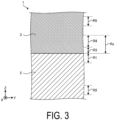
- FIG. 3 is a schematic enlarged view of an III portion illustrated in FIG. 2 .
- a region including an interface with the glaze layer 3 is defined as a first region R1.
- the main component of the glaze layer 3 is impregnated into the base 2 from the interface between the base 2 and the glaze layer 3.
- the concentration of the main component of the glaze layer 3 gradually decreases from the interface between the base 2 and the glaze layer 3 toward a center portion of the base 2 in a depth direction.
- a range in which the concentration of the main component (for example, Si) of the glaze layer 3 inclines (decreases) along the depth direction of the base 2 may be specified as the first region R1.
- the Si concentration in the center portion of the base 2 in the depth direction is defined as a "center portion concentration” and the interface between the base 2 and the glaze layer 3 is defined as “one end portion” of the first region R1
- "the other end portion” of the first region R1 may be located at a position in the depth direction of the base 2 at which Si concentration coincides with the central portion concentration.
- the first region R1 may be a region from the interface with the glaze layer 3 to a depth of 70 ⁇ m.
- a region farther from the glaze layer 3 than the first region R1 in other words, a region located more inward in the base 2 than the first region R1 (a deeper portion when viewed from the glaze layer 3 side) is defined as a second region R2.
- one end portion of the second region R2 (end portion on the glaze layer 3 side) may be separated from the other end portion of the first region R1 by at least 150 ⁇ m.
- the second region R2 is a region from a depth of 1000 ⁇ m (1 mm) to a depth of 1020 ⁇ m with reference to the interface with the glaze layer 3.
- a crystal grain size in the first region R1 may be smaller than a crystal grain size in the second region R2.
- the crystal grain size of the second region R2 By making the crystal grain size of the second region R2 larger than the crystal grain size of the first region R1, the following effect is obtained. That is, the Young's modulus of the second region R2 having the larger crystal grain size is larger than the Young's modulus of the first region R1 having the smaller crystal grain size. For this reason, when repeated stresses (tensile stresses or compressive stresses) are simultaneously applied to the first region R1 and the second region R2, the generation of fine cracks from the second region R2 is suppressed, and thus the occurrence of fatigue failure from the second region R2 is suppressed. This is because the larger the Young's modulus is, the more elastic deformation due to stress application is suppressed.
- fatigue fracture refers to the formation of fine cracks in the base 2 when a stress smaller than the fracture strength is applied many times, and eventually these fine cracks become larger, resulting in a decrease in mechanical strength or causing fracture (breakage).
- the first region R1 has a smaller crystal grain size than the second region R2, and thus, although the first region R1 has a smaller Young's modulus than the second region R2, the first region R1 has a large flexural strength and can suppress the generation of fine cracks when subjected to repeated stresses.
- the ceramic structure 1 maintains high mechanical flexural strength and is less likely to cause fatigue failure even when subjected to repeated stresses.
- the following effect is also obtained. That is, by making the crystal grain size of the second region R2 larger, the thermal conductivity of the second region R2 can be made higher than the thermal conductivity of the first region R1.
- the heat when heat is transferred from the glaze layer 3 to the base 2, the heat can be efficiently transferred from the first region R1 to the second region R2. This suppresses the generation of thermal stress between the first region R1 and the second region R2. Accordingly, even when thermal stress is applied to the base 2 due to a rapid temperature change, cracking or fracture of the base 2 is suppressed.
- a void ratio in the first region R1 may be lower than a void ratio in the second region R2.
- the ceramic structure 1 has a high mechanical strength.
- the ceramic structure 1 may include, between the first region R1 and the second region R2, a region having an average crystal grain size smaller than an average grain size of the second region R2. In other words, the ceramic structure 1 may include, between the first region R1 and the second region R2, a region having an average crystal grain size equivalent to an average grain size of the first region R1.
- the glaze layer 3 may contain Si as a metal element as described above. Compared with a center portion of the glaze layer 3 in a thickness direction, the Si concentration of the glaze layer 3 may be lower in a region closer to the base 2 than the center portion.
- the glaze layer 3 may contain Ca as a metal element as described above. Compared with a center portion of the glaze layer 3 in a thickness direction, the Ca concentration of the glaze layer 3 is higher in a region closer to the base 2 than the center portion.
- the glaze layer 3 may include a Si concentration increase region Rx in which the Si concentration increases with increasing distance from the interface with the base 2.
- the thermal expansion coefficient of the glaze layer 3 in contact with the base 2 can be made close to the thermal expansion coefficient of the base 2 by reducing the Si content in the glaze layer 3 close to the base 2.
- the difference in thermal expansion coefficient between the base 2 and the glaze layer 3 is reduced, and the residual stress between the base 2 and the glaze layer 3 is reduced. Accordingly, the mechanical strength of the ceramic structure 1 is improved.
- the Si concentration increase region Rx may include a third region R3 including the interface with the base 2 and a fourth region R4 continuous with the third region R3 and farther from the base 2 than the third region R3.
- the rate of increase of the Si concentration in the third region R3 may be greater than the rate of increase of the Si concentration in the fourth region R4.
- the glaze layer 3 may include a fifth region R5 farther from the base 2 than the fourth region R4 in the Si concentration increase region Rx.
- the rate of change of the Si concentration in the fifth region R5 may be smaller than the rate of change of the Si concentration in the fourth region R4.
- the Si concentration in the fifth region R5 may be substantially constant.
- the Si concentration in the first region R1 is higher than the Si concentration in the center portion of the base 2 in the depth direction, for example, the Si concentration in the second region R2.
- the base 2 may contain Al as described above.
- the Al concentration in the first region R1 may be lower than the Al concentration in the center portion of the base 2 in the depth direction, for example, the Al concentration in the second region R2.
- the thickness of a glaze layer 33 located on an edge portion between the first wall portion 21 and the second wall portion 22 (a side of the inner bottom surface of the container) may be thicker than the thickness of a glaze layer 31 located on the first wall portion 21 and the thickness of a glaze layer 32 located on the second wall portion 22.
- Thermal shock tends to concentrate on the edge portion between the first wall portion 21 and the second wall portion 22.
- the thickness of the glaze layer 31 on the edge portion relatively thick, the strength of the edge is increased and, consequently, the generation of cracks and/or breaks in the edge portion due to thermal shock is suitably suppressed.
- the thickness of the glaze layer 3 located on an edge portion between the first wall portions 21 adjacent to each other may be thicker than the thickness of the glaze layer 31 located on the first wall portion 21 and the thickness of the glaze layer 32 located on the second wall portion 22.
- an unglazed body of a ceramic is prepared.
- the unglazed body is obtained by heat-treating a green body of the base 2 at a temperature lower by 200 to 800°C than a sintering temperature (sintering temperature in the absence of a glaze).
- the unglazed body is obtained by heat-treating the green body of the base 2 at 1000°C for 30 minutes.
- a procedure for preparing the green body of the base 2 is as follows. First, an aluminum oxide (Al 2 O 3 ) powder as a main raw material of the base 2, a silicon oxide (SiO 2 ) powder as a sintering aid, a calcium carbonate (CaCO 3 ) powder, a magnesium carbonate (MgCO 3 ) powder, and the like are mixed in predetermined proportions, and then subjected to wet grinding to obtain a primary slurry. Then, a binder is added to and mixed with the primary slurry to obtain a secondary slurry. The secondary slurry is spray-dried to prepare granules. The prepared granules are uniaxially press-molded into a container shape to obtain the green body.
- Al 2 O 3 aluminum oxide
- SiO 2 silicon oxide
- CaCO 3 calcium carbonate
- MgCO 3 magnesium carbonate
- a paste containing a glaze for example, a known glaze raw material powder is mixed with a liquid and a binder and kneaded to obtain a glaze paste or a low-viscosity liquid glaze.
- the glaze paste is applied to an unglazed body having an approximate porosity (void ratio) of about 30 to 50 vol%.
- the method of application is not particularly limited and may be, for example, spraying, atomizing, impregnation, or the like.
- the glaze paste is stored in a tank, and the unglazed body is immersed in the tank, and thereby the unglazed body can be impregnated with the glaze paste.
- the unglazed body is taken out from the tank, and the glaze paste accumulated inside the container is discharged. At this time, a relatively large amount of the glaze paste remains on the four sides of the inner bottom surface of the container, and thus the thickness of the glaze layer on the four sides of the inner bottom surface of the container becomes relatively thick.
- the unglazed body with the glaze applied thereon is heat-treated so that the sintering of the unglazed body and the densification (solidification) of the glaze are simultaneously performed.
- the unglazed body with the glaze applied thereon is heat-treated at 1350°C or higher and 1450°C or lower for 2 hours.
- the ceramic structure 1 according to an embodiment can be obtained.
- a part of the glaze paste enters into open pores and communication pores of the unglazed body, and thereby a part of the glaze remains on a surface of the unglazed body.
- the sintering proceeds with the glaze remaining in the open pores and the communication pores of the unglazed body.
- the open pores refer to pores opening on an application surface to which the glaze is applied.
- the communication pores refer to pores communicating from the application surface to the inside of the unglazed body.
- the glaze is initially in a paste state, and when melted by heat treatment, the glaze becomes a low-viscosity melt. After the temperature is lowered in the sintering step, the glaze remains solidified in the open pores and the communication pores.
- the crystal grain size in the portions of the base 2 in which the glaze entered is smaller than the crystal grain size in other portions.
- the void ratio in the portions of the base 2 in which the glaze entered is lower than the void ratio in other portions.
- the void ratio in the first region R1 of the base 2 is 1/3 or less of the void ratio in the second region R2 of the base 2. More specifically, the void ratio in the first region R1 of the base 2 is 2% or less.
- a method for forming the Si concentration increase region Rx in the glaze layer 3 is the same as or similar to the method described above.
- the glaze may be applied in multiple layers. At this time, for example, by adjusting the Si concentration in the glaze of a first layer to be lower than the Si concentration in the glaze of a second layer, the Si concentration increase region Rx can be suitably formed.
- the unglazed body may be subjected to a drying treatment after the first layer of the glaze is applied, or the second layer of the glaze may be successively applied without performing the drying treatment.
- the inventors of the present application measured the crystal grain size and the void ratio of the base, the flexural strength, the Si concentration and the Ca concentration of the glaze layer, and the Si concentration and the Al concentration of the base.
- composition of the ceramic structure used in the measurement is as follows.
- the inventors of the present application measured the crystal grain size of a base of a ceramic structure according to the example and the grain size of a base of a ceramic structure according to a comparative example.
- the ceramic structure according to the comparative example was obtained by sintering a base, applying a glaze to the sintered base, and performing heat treatment to densify the glaze layer.
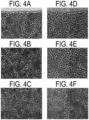
- a cut surface of each ceramic structure was polished to obtain a mirror surface, and the obtained mirror surface was observed at measurement locations using a SEM (scanning electron microscope) at a magnification of about 3000 times. Then, the average crystal grain size was calculated based on the obtained SEM image using a coding method.
- the average crystal grain size may be calculated based on a BEM image (backscattered electron image) instead of the SEM image (secondary electron image).
- the measurement locations were three regions, that is, a region from the interface between the base and the glaze layer to a depth of 20 ⁇ m inside the base (corresponding to a part of the first region R1 described above, and hereinafter referred to as an "interface region”), a region from a depth of 100 ⁇ m to a depth of 120 ⁇ m with reference to the interface between the base and the glaze layer (hereinafter referred to as an "intermediate region”), and a region from a depth of 1000 ⁇ m (1 mm) to a depth of 1020 ⁇ m with reference to the interface between the base and the glaze layer (corresponding to the second region R2 described above, and hereinafter referred to as a "deep region”).
- FIG. 4 shows SEM images of the ceramic structure according to the example and the ceramic structure according to the comparative example.
- FIGs. 4A to 4C are SEM images of the ceramic structure according to the comparative example
- FIGs. 4D to 4F are SEM images of the ceramic structure according to the example.
- FIGs. 4A and 4D are SEM images of the interface regions
- FIGs. 4B and 4E are SEM images of the intermediate regions
- FIGs. 4C and 4F are SEM images of the deep regions.
- FIG. 5 is a table showing the measurement results of the average crystal grain sizes of the base in the ceramic structure according to the example and the base in the ceramic structure according to the comparative example.
- the crystal grain size of the base in the ceramic structure according to the comparative example was roughly the same in the interface region, the intermediate region, and the deep region.
- FIGs. 4D to 4F show that the crystal grain size of the base in the ceramic structure according to the example was smaller in the interface region than in the deep region. Specifically, the crystal grain size in the interface region was about 80% of the crystal grain size in the deep region.
- the crystal grain size of the base in the ceramic structure according to the comparative example was 1.8 ⁇ m in the interface region, 1.7 ⁇ m in the intermediate region, and 1.7 ⁇ m in the deep region.
- the crystal grain size of the base in the ceramic structure according to the example was 1.4 ⁇ m in the interface region, 1.4 ⁇ m in the intermediate region, and 1.8 ⁇ m in the deep region.
- the crystal grain size of the base in the first region including the interface with the glaze layer was smaller than the crystal grain size of the base in the second region farther from the glaze layer than the first region.
- the inventors of the present application measured the void ratio of the base of the ceramic structure according to the example and the void ratio of the base of the ceramic structure according to the comparative example.
- the above-described mirror surface was observed by using a metallurgical microscope at a magnification of about 200 times, and an obtained image was binarized by using the image analysis software "A zou-kun" (trade name, manufactured by Asahi Kasei Engineering Corporation, and, hereinafter, when the image analysis software "A zou-kun” is mentioned in the following, it refers to the image analysis software manufactured by the Asahi Kasei Engineering Corporation). Then, the binarized image was analyzed to calculate the void ratio.
- Measurement locations are the above described three regions of the interface region, the intermediate region, and the deep region.
- the binarization of the image may be executed by using image analysis software other than "A zou-kun".
- image analysis software other than "A zou-kun” for example, a digital microscope manufactured by KEYENCE CORPORATION (for example, VHX-5000, VHX-7000, or VHX-8000) can be used.
- FIG. 6 is a table showing the measurement results of the void ratios of the base in the ceramic structure according to the example and the base in the ceramic structure according to the comparative example.
- the void ratio of the base in the ceramic structure according to the comparative example was 2.5% in the interface region, 7.0% in the intermediate region, and 7.2% in the deep region.
- the void ratio of the base in the ceramic structure according to the example was 0.8% in the interface region, 6.0% in the intermediate region, and 5.9% in the deep region.
- the void ratio of the base in the first region including the interface with the glaze layer was smaller than the void ratio of the base in the second region farther from the glaze layer than the first region.
- the void ratio in the first region was 1/6 of the void ratio in the second region.
- the inventors of the present application measured the flexural strength of the ceramic structure according to the example and the flexural strength of the ceramic structure according to the comparative example using a plurality of measurement samples having different glaze layer thicknesses.
- the glaze layer thicknesses were 5 patterns of 50 ⁇ m, 65 ⁇ m, 75 ⁇ m, 100 ⁇ m and 180 ⁇ m.
- FIG. 7 is an explanatory view of flexural strength measurement.
- measurement samples having a plate-like shape were prepared.
- the dimensions of each measurement sample were 30 mm length, 15 mm width, and 2 mm thickness.
- the measurement sample was placed on the ridge portions of two support members having a triangular prism shape with a glaze layer facing downward. The distance between the two support members was 25 mm.
- An intermediate position between the two support members on the measurement sample was pressed from above the measurement sample by using a terminal. The terminal linearly pressed the measurement sample in parallel with the ridge portions of the support members. Then, the pressure applied to the measurement sample from the terminal when the measurement sample was broken was calculated as a flexural strength.
- FIG. 8 is a table showing the flexural strength measurement results of the ceramic structure according to the example and the ceramic structure according to the comparative example.
- the flexural strength of the ceramic structure according to the comparative example was 307 MPa for a glaze layer thickness of 50 ⁇ m, 280 MPa for a glaze layer thickness of 65 ⁇ m, 373 MPa for a glaze layer thickness of 75 ⁇ m, 378 MPa for a glaze layer thickness of 100 ⁇ m, and 334 MPa for a glaze layer thickness of 180 ⁇ m.
- the flexural strength of the ceramic structure according to the embodiment was 349 MPa for a glaze layer thickness of 50 ⁇ m, 398 MPa for a glaze layer thickness of 65 ⁇ m, 463 MPa for a glaze layer thickness of 75 ⁇ m, 441 MPa for a glaze layer thickness of 100 ⁇ m, and 489 MPa for a glaze layer thickness of 180 ⁇ m.
- the ceramic structure according to the example has higher mechanical strength than the ceramic structure according to the comparative example.
- the mechanical strength of the ceramic structure according to the example increases with the increasing glaze layer thickness.
- the inventors of the present application measured the Si concentration and Ca concentration of the glaze layer in the ceramic structure according to the example.
- the Si concentration and the Ca concentration were measured by using a wavelength-dispersive X-ray spectroscopy (WDS) apparatus.
- WDS wavelength-dispersive X-ray spectroscopy
- FIGs. 9 and 10 are graphs showing the measurement results of the Si concentration of the glaze layer in the ceramic structure according to the example.
- FIG. 9 shows the measurement results of the Si concentration in a measurement range of 30 ⁇ m in the depth direction including the outer surface of the glaze layer (a surface located on the opposite side to the interface with the base).
- FIG. 10 shows the measurement results of the Si concentration in a measurement range of 30 ⁇ m in the depth direction including the interface with the base.
- the position of the outer surface of the glaze layer is around 30 ⁇ m.
- the position of the interface between the glaze layer and the base is around 5 ⁇ m.
- the behaviors of the graphs at measurement start points and measurement end points depend on the specifications of the measurement apparatus, and thus are disregarded. This is also true for FIGs. 11 to 14 to be described later.
- the glaze layer according to the example includes a Si concentration increase region in which the Si concentration increases with increasing distance from the interface with the base.
- the Si concentration increase region is, for example, a region from the interface with the base (the 5 ⁇ m position shown in FIG. 10 ) to a depth of 20 ⁇ m (the 25 ⁇ m position shown in FIG. 10 ).
- the rate of increase of the Si concentration in a region including the interface with the base is larger than the rate of increase of the Si concentration in a region farther from the base than the third region (corresponding to the fourth region R4).
- the third region here is, for example, a region from the interface with the base to a depth of 2 ⁇ m.
- the fourth region here is a region other than the third region in the Si concentration increase region.
- the rate of change of the Si concentration in a region still farther from the base than the fourth region is smaller than the rate of change of the Si concentration in the fourth region.
- the fifth region here is, for example, the 0 to 10 ⁇ m region shown in FIG. 9 .
- the Si concentration in the fifth region is substantially constant.
- FIGs. 11 and 12 are graphs showing the measurement results of the Ca concentration of the glaze layer in the ceramic structure according to the example.
- FIG. 11 shows the measurement results of the Ca concentration in a measurement range of 30 ⁇ m in the depth direction including the outer surface of the glaze layer.
- FIG. 12 shows the measurement results of the Ca concentration in a measurement range of 30 ⁇ m in the depth direction including the interface with the base.
- the glaze layer according to the example includes a Ca concentration increase region in which the Ca concentration increases with increasing distance from the interface with the base.
- the Ca concentration increase region is, for example, a region from the interface with the base (the 5 ⁇ m position shown in FIG. 12 ) to a depth of 7.5 ⁇ m (the 12.5 ⁇ m position shown in FIG. 12 ).
- the rate of increase of the Ca concentration in a region including the interface with the base (hereinafter referred to as an eighth region) is larger than the rate of increase of the Ca concentration in a region farther from the base than the eighth region (hereinafter referred to as a ninth region).
- the eighth region is, for example, a region from the interface with the base to a depth of 2 ⁇ m.
- the ninth region is a region other than the eighth region in the Si concentration increase region.
- the inventors of the present application measured the Si concentration and the Al concentration of the base in the ceramic structure according to the example.
- a method for measuring the Si concentration and the Al concentration in the base is the same as or similar to the method for measuring the Si concentration and the Ca concentration in the glaze layer described above.
- FIG. 13 is a graph showing the measurement results of the Si concentration of the base in the ceramic structure according to the example.
- FIG. 14 is a graph showing the measurement results of the Al concentration of the base in the ceramic structure according to the example.
- FIGs. 13 and 14 show the measurement results of the Si concentration and the Ca concentration in a measurement range of 90 ⁇ m in the depth direction including the interface between the base and the glaze layer.
- the position of the interface between the glaze layer and the base is around 40 ⁇ m, and a range of 0 to 40 ⁇ m corresponds to the base and a range of 40 to 90 ⁇ m corresponds to the glaze layer.
- FIG. 13 shows that the Si concentration in a region of the base including the interface with the glaze layer (corresponding to the interface region) is higher than the Si concentration in a region of the base farther from the glaze layer than the interface region.
- the interface region here is, for example, a region from the interface between the base and the glaze layer (the 40 ⁇ m position shown in FIG. 13 ) to a depth of 20 ⁇ m (the 20 ⁇ m position shown in FIG. 13 ).
- the region of the base farther from the glaze layer than the interface region is, for example, a region from a position 20 ⁇ m deeper than the interface region (0 ⁇ m shown in FIG. 13 ) to the lower end of the interface region (20 ⁇ m shown in FIG. 13 ).
- FIG. 14 shows that the Al concentration in a region of the base including the interface with the glaze layer (corresponding to the interface region) is lower than the Al concentration in a region of the base farther from the glaze layer than the interface region.
- the interface region here is, for example, a region from the interface between the base and the glaze layer (the 40 ⁇ m position shown in FIG. 14 ) to a depth of 20 ⁇ m (the 20 ⁇ m position shown in FIG. 14 ).
- the region of the base farther from the glaze layer than the interface region is, for example, a region from a position 20 ⁇ m deeper than the interface region (0 ⁇ m shown in FIG. 14 ) to the lower end of the interface region (20 ⁇ m shown in FIG. 14 ).
- the ceramic structure according to the example was cut along a plane orthogonal to the first wall portion and the second wall portion, and the thickness of the glaze layer located in the cut surface was measured. Measurement was performed at three locations as indicated by the reference signs 31 to 33 shown in FIG. 2 . Then, the thickness of the glaze layer located on the first wall portion was 260 ⁇ m, the thickness of the glaze layer located on the second wall portion was 295 ⁇ m, and the thickness of the glaze layer located on the edge portion between the first wall portion and the second wall portion was 596 ⁇ m. These results show that the thickness of the glaze layer is relatively thick on the edge portion between the first wall portion and the second wall portion.
- the thickness of the glaze layer on an edge portion between two adjacent first wall portions was also measured. Specifically, the ceramic structure according to the example was cut along a plane orthogonal to the first wall portion and parallel to the second wall portion, and the thickness of the glaze layer located in the cut surface was measured. Then, the thickness of the glaze layer located on the edge portion between the two adjacent first wall portions was 360 ⁇ m.
- the thickness of the glaze layer on four corners inside the base was also measured. Specifically, the ceramic structure according to the example was cut along a plane passing through both an outer edge portion and an inner edge portion between two adjacent first wall portions, and the thickness of the glaze layer located in the cut surface was measured. Then, the thickness of the glaze layer located on the four corners inside the base was 851 ⁇ m.
- the thickness of the glaze layer is large at the edge portion between the first wall portion and the second wall portion (including the four corners inside the base).
- a ceramic structure with a glaze layer (for example, the ceramic structure 1) includes a base made of ceramic (as an example, the base 2) and a glaze layer (for example, the glaze layer 3) located on the base.
- the crystal grain size of the base in a first region (for example, the first region R1) including an interface with the glaze layer is smaller than the crystal grain size of the base in a second region (for example, the second region R2) farther from the glaze layer than the first region.
- a ceramic structure with a glaze layer (for example, the ceramic structure 1) includes a base made of ceramic (for example, the base 2) and a glaze layer (for example, the glaze layer 3) located on the base.
- the void ratio of the base in a first region (for example, the first region R1) including an interface with the glaze layer is smaller than the void ratio of the base in a second region (for example, the second region R2) farther from the glaze layer than the first region.
- the mechanical strength can be improved.
- the base 2 is made of an aluminum oxide ceramic
- the base 2 may be made of a material other than aluminum oxide ceramic.
- the material other than the aluminum oxide ceramic may be, for example, cordierite, forsterite, zirconia, or the like.
Landscapes
- Chemical & Material Sciences (AREA)
- Engineering & Computer Science (AREA)
- Ceramic Engineering (AREA)
- Materials Engineering (AREA)
- Organic Chemistry (AREA)
- Structural Engineering (AREA)
- Manufacturing & Machinery (AREA)
- General Chemical & Material Sciences (AREA)
- Geochemistry & Mineralogy (AREA)
- Life Sciences & Earth Sciences (AREA)
- Inorganic Chemistry (AREA)
- Chemical Kinetics & Catalysis (AREA)
- Composite Materials (AREA)
- Structure Of Printed Boards (AREA)
- Laminated Bodies (AREA)
Abstract
Description
- The present disclosure relates to a ceramic structure with a glaze layer.
- Conventionally, there has been known a technique for providing a glaze layer to a ceramic structure, for example, with the object of ensuring airtightness, insulation, and the like.
-
Patent Document 1 discloses a method for manufacturing a ceramic structure with a glaze layer by preparing a sintered ceramic body, applying a glaze paste to the prepared sintered ceramic body, and then heat-treating the ceramic structure with the glaze paste applied thereon. - Patent Document 1:
JP 2007-252524 A - In an aspect of the present disclosure, a ceramic structure with a glaze layer includes a base made of a ceramic and a glaze layer located on the base. The base includes a first region including an interface with the glaze layer, and a second region farther from the glaze layer than the first region. A crystal grain size in the first region is smaller than a crystal grain size in the second region.
-
-
FIG. 1 is a schematic perspective view of a ceramic structure with a glaze layer according to an embodiment. -
FIG. 2 is a schematic cross-sectional view of the ceramic structure with a glaze layer according to an embodiment. -
FIG. 3 is a schematic enlarged view of an III portion illustrated inFIG. 2 . -
FIG. 4 shows SEM images of a ceramic structure according to an example and a ceramic structure according to a comparative example. -
FIG. 5 is a table showing the measurement results of the average crystal grain sizes of a base in the ceramic structure according to the example and a base in the ceramic structure according to the comparative example. -
FIG. 6 is a table showing the measurement results of the void ratios of the base in the ceramic structure according to the example and the base in the ceramic structure according to the comparative example. -
FIG. 7 is an explanatory view of flexural strength measurement. -
FIG. 8 is a table showing the flexural strength measurement results of the ceramic structure according to the example and the ceramic structure according to the comparative example. -
FIG. 9 is a graph showing the measurement results of the Si concentration of a glaze layer in the ceramic structure according to the example. -
FIG. 10 is a graph showing the measurement results of the Si concentration of the glaze layer in the ceramic structure according to the example. -
FIG. 11 is a graph showing the measurement results of the Ca concentration of the glaze layer in the ceramic structure according to the example. -
FIG. 12 is a graph showing the measurement results of the Ca concentration of the glaze layer in the ceramic structure according to the example. -
FIG. 13 is a graph showing the measurement results of the Si concentration of the base in the ceramic structure according to the example. -
FIG. 14 is a graph showing the measurement results of the Al concentration of the base in the ceramic structure according to the example. - Modes (hereinafter, referred to as "embodiments") for implementing a ceramic structure with a glaze layer according to the present disclosure will be described in detail below with reference to the accompanying drawings. The embodiments described below do not intend to limit the ceramic structure with a glaze layer according to the present disclosure. In addition, embodiments can be appropriately combined so as not to contradict each other in terms of processing content. In the following embodiments, the same portions are denoted by the same reference signs, and overlapping explanations are omitted.
- In the embodiments described below, expressions such as "constant", "orthogonal", "perpendicular", and "parallel" may be used, but these expressions do not need to be exactly "constant", "orthogonal", "perpendicular", and "parallel". In other words, it is assumed that the above expressions allow deviations in manufacturing accuracy, installation accuracy, or the like.
- A known ceramic structure with a glaze layer has room for further improvement in terms of mechanical strength. The present disclosure provides a ceramic structure with a glaze layer that can improve mechanical strength.
-
FIG. 1 is a schematic perspective view of a ceramic structure with a glaze layer according to an embodiment.FIG. 2 is a schematic cross-sectional view of the ceramic structure with a glaze layer according to an embodiment. Specifically,FIG. 2 illustrates a cross section orthogonal to afirst wall portion 21 and asecond wall portion 22 among cross sections of aceramic structure 1. Abase 2 of theceramic structure 1 with a glaze layer may have a plate-like shape. An opening may be disposed in thesecond wall portion 22 inFIG. 2 . - As illustrated in
FIGs. 1 and 2 , theceramic structure 1 with a glaze layer according to an embodiment (hereinafter simply referred to as "ceramic structure 1") includes thebase 2 and aglaze layer 3. - The
base 2 may have a container shape. The container shape may be, for example, a shape that includes a plate-shaped portion including one main surface and another main surface, and a side wall portion integrally connected to an end portion side of the plate-shaped portion and extending in a direction from the one main surface side toward the another main surface side, in which an end portion of the side wall portion on a side opposite to the plate-shaped portion is open. As an example, as illustrated inFIGs. 1 and 2 , thebase 2 may have, for example, four first wall portions 21 (each equivalent to the side wall portion) and one second wall portion 22 (equivalent to the plate-shaped portion) continuous with the fourfirst wall portions 21. Theceramic structure 1 may be open on the opposite side to thesecond wall portion 22. A recessed portion or a protruding portion may be located at thefirst wall portion 21 or thesecond wall portion 22. - Although the
second wall portion 22 is provided herein to constitute a lower wall of theceramic structure 1, thesecond wall portion 22 is not limited thereto, and may constitute an upper wall of theceramic structure 1. That is, theceramic structure 1 may be upside down from the state illustrated inFIG. 1 . Although an example in which the contour shape of thebase 2 is a quadrilateral shape in a plan view is illustrated here, the contour shape of thebase 2 may be a polygonal shape other than a quadrilateral shape or may be a circular shape. - In an embodiment, the
ceramic structure 1 may be used as a heat-resistant container. For example, theceramic structure 1 may be used as a container for storing a high-temperature substance (for example, molten metal). The high-temperature substance is not limited to a liquid, and may be a solid. When the high-temperature substance is a solid, an opening may be disposed in a bottom surface and/or a wall surface of theceramic structure 1 serving as the heat-resistant container. Theceramic structure 1 may be used as a container whose inner wall surface is at least partly exposed to plasma. In that case, an opening may be disposed in a bottom surface and/or a wall surface of theceramic structure 1. Further, the opening may be closed by a member (for example, a heat-resistant metal member) other than theceramic structure 1. - In an embodiment, the
ceramic structure 1 is made of a ceramic. As the ceramic constituting theceramic structure 1, an aluminum oxide ceramic, a silicon nitride ceramic, an aluminum nitride ceramic, a silicon carbide ceramic, or the like may be used. - The
ceramic structure 1 made of an aluminum oxide ceramic exhibits excellent mechanical characteristics while being relatively inexpensive among ceramics in terms of raw material cost and manufacturing cost as well. In addition, discarding theceramic structure 1 with a glaze layer is less likely to cause environmental pollution. - An aluminum oxide ceramic may contain 85 mass% or more of alumina (Al2O3) from among 100 mass% of all components constituting the ceramic. That is, a ceramic containing alumina as a main component is called an aluminum oxide ceramic. In the present embodiment, the
base 2 may be made of an aluminum oxide ceramic (that is, a ceramic containing alumina as a main component). In the embodiment, thebase 2 may contain 90 mass% or more of alumina. In the embodiment, the content percentage of alumina in thebase 2 may be 96 mass% or less. - For example, the method below can be used to confirm the material of the
base 2. First, thebase 2 is measured using an X-ray diffractometer (XRD), and an obtained value of 2θ (where 2θ is a diffraction angle) is checked against a JCPDS card. Next, a quantitative analysis of aluminum (Al) is performed using an ICP emission spectrophotometer (ICP) or an X-ray fluorescent (XRF) analyzer. Then, when the content percentage of aluminum oxide (Al2O3), which is a value converted from the content percentage of Al measured by ICP or XRF, is 85 mass% or greater, the material of thebase 2 is an aluminum oxide ceramic. - The
base 2 may contain a component used as a sintering aid. Specifically, thebase 2 may contain Si (silicon). The sintering aid may contain, for example, Ca (calcium), Mg (magnesium), or the like in addition to Si. - The
base 2 may have a density of 3.5 g/cm3 or more. In thebase 2, an area ratio of pores measured in a cross section may be 0.5% or less. Such a dense base has a particularly high strength. - The
glaze layer 3 may be disposed on an inner surface of thebase 2. Theglaze layer 3 may be provided on the inner surface of thebase 2, for example, in order to ensure the airtightness, the insulation, and the like of theceramic structure 1. - As described above, by providing the
glaze layer 3 on the inner surface of thebase 2 having a container shape, stress remains in a direction in which the opening of the container is closed (a direction toward the center of the opening), and thus the mechanical strength of theceramic structure 1 is improved. - Although
FIGs. 1 and 2 illustrate an example in which theglaze layer 3 is disposed only on the inner surface of thebase 2, theglaze layer 3 may also be disposed on an outer surface of thebase 2. Thebase 2 may be entirely covered by theglaze layer 3. - The
glaze layer 3 may contain at least Si (silicon) as a metal element. For example, theglaze layer 3 may contain Al (aluminum), Ca (calcium), K (potassium), Na (sodium), or the like in addition to Si as a metal element. - When both of the
base 2 and theglaze layer 3 contain Si, the chemical bonding between thebase 2 and theglaze layer 3 is improved. Accordingly, the mechanical strength of theceramic structure 1 is improved. -
FIG. 3 is a schematic enlarged view of an III portion illustrated inFIG. 2 . As illustrated inFIG. 3 , in thebase 2, a region including an interface with theglaze layer 3 is defined as a first region R1. - As will be described later, the main component of the
glaze layer 3 is impregnated into thebase 2 from the interface between thebase 2 and theglaze layer 3. The concentration of the main component of theglaze layer 3 gradually decreases from the interface between thebase 2 and theglaze layer 3 toward a center portion of thebase 2 in a depth direction. Thus, a range in which the concentration of the main component (for example, Si) of theglaze layer 3 inclines (decreases) along the depth direction of thebase 2 may be specified as the first region R1. Specifically, when the Si concentration in the center portion of thebase 2 in the depth direction is defined as a "center portion concentration" and the interface between thebase 2 and theglaze layer 3 is defined as "one end portion" of the first region R1, "the other end portion" of the first region R1 may be located at a position in the depth direction of thebase 2 at which Si concentration coincides with the central portion concentration. - For example, the first region R1 may be a region from the interface with the
glaze layer 3 to a depth of 70 µm. In thebase 2, a region farther from theglaze layer 3 than the first region R1, in other words, a region located more inward in thebase 2 than the first region R1 (a deeper portion when viewed from theglaze layer 3 side) is defined as a second region R2. - For example, one end portion of the second region R2 (end portion on the
glaze layer 3 side) may be separated from the other end portion of the first region R1 by at least 150 µm. For example, the second region R2 is a region from a depth of 1000 µm (1 mm) to a depth of 1020 µm with reference to the interface with theglaze layer 3. - In the
ceramic structure 1 according to an embodiment, a crystal grain size in the first region R1 may be smaller than a crystal grain size in the second region R2. - In this manner, by making the crystal grain size of the first region R1 smaller than the crystal grain size of the second region R2, the mechanical strength of the
base 2 is improved. - By making the crystal grain size of the second region R2 larger than the crystal grain size of the first region R1, the following effect is obtained. That is, the Young's modulus of the second region R2 having the larger crystal grain size is larger than the Young's modulus of the first region R1 having the smaller crystal grain size. For this reason, when repeated stresses (tensile stresses or compressive stresses) are simultaneously applied to the first region R1 and the second region R2, the generation of fine cracks from the second region R2 is suppressed, and thus the occurrence of fatigue failure from the second region R2 is suppressed. This is because the larger the Young's modulus is, the more elastic deformation due to stress application is suppressed. Here, fatigue fracture refers to the formation of fine cracks in the
base 2 when a stress smaller than the fracture strength is applied many times, and eventually these fine cracks become larger, resulting in a decrease in mechanical strength or causing fracture (breakage). On the other hand, the first region R1 has a smaller crystal grain size than the second region R2, and thus, although the first region R1 has a smaller Young's modulus than the second region R2, the first region R1 has a large flexural strength and can suppress the generation of fine cracks when subjected to repeated stresses. As a result, in an embodiment, theceramic structure 1 maintains high mechanical flexural strength and is less likely to cause fatigue failure even when subjected to repeated stresses. - Further, by making the crystal grain size of the second region R2 larger than the crystal grain size of the first region R1, the following effect is also obtained. That is, by making the crystal grain size of the second region R2 larger, the thermal conductivity of the second region R2 can be made higher than the thermal conductivity of the first region R1. Thus, when heat is transferred from the
glaze layer 3 to thebase 2, the heat can be efficiently transferred from the first region R1 to the second region R2. This suppresses the generation of thermal stress between the first region R1 and the second region R2. Accordingly, even when thermal stress is applied to thebase 2 due to a rapid temperature change, cracking or fracture of thebase 2 is suppressed. - In the
ceramic structure 1 according to an embodiment, a void ratio in the first region R1 may be lower than a void ratio in the second region R2. - By lowering the void ratio of the first region R1 in contact with the
glaze layer 3 as described above, the generation of cracks in thebase 2 from the interface between thebase 2 and theglaze layer 3 is suppressed. Thus, in an embodiment, theceramic structure 1 has a high mechanical strength. - In an embodiment, the
ceramic structure 1 may include, between the first region R1 and the second region R2, a region having an average crystal grain size smaller than an average grain size of the second region R2. In other words, theceramic structure 1 may include, between the first region R1 and the second region R2, a region having an average crystal grain size equivalent to an average grain size of the first region R1. - In an embodiment, the
glaze layer 3 may contain Si as a metal element as described above. Compared with a center portion of theglaze layer 3 in a thickness direction, the Si concentration of theglaze layer 3 may be lower in a region closer to thebase 2 than the center portion. - By reducing the amount of Si contained in the
glaze layer 3 on thebase 2 side as described above, the residual stress applied to thebase 2 is reduced and the mechanical strength of theceramic structure 1 is improved. - In an embodiment, the
glaze layer 3 may contain Ca as a metal element as described above. Compared with a center portion of theglaze layer 3 in a thickness direction, the Ca concentration of theglaze layer 3 is higher in a region closer to thebase 2 than the center portion. - By increasing the amount of Si contained in the
glaze layer 3 on thebase 2 side as described above, the residual stress applied to thebase 2 is reduced and the mechanical strength of theceramic structure 1 is improved. - As illustrated in
FIG. 3 , theglaze layer 3 may include a Si concentration increase region Rx in which the Si concentration increases with increasing distance from the interface with thebase 2. - By setting the Si content of the
glaze layer 3 such that the farther from thebase 2, the larger the Si content, thebase 2 can be caused to generate compressive stress. Accordingly, the mechanical strength of theceramic structure 1 is improved. From another viewpoint, the thermal expansion coefficient of theglaze layer 3 in contact with thebase 2 can be made close to the thermal expansion coefficient of thebase 2 by reducing the Si content in theglaze layer 3 close to thebase 2. As a result, the difference in thermal expansion coefficient between thebase 2 and theglaze layer 3 is reduced, and the residual stress between thebase 2 and theglaze layer 3 is reduced. Accordingly, the mechanical strength of theceramic structure 1 is improved. - The Si concentration increase region Rx may include a third region R3 including the interface with the
base 2 and a fourth region R4 continuous with the third region R3 and farther from thebase 2 than the third region R3. In this case, the rate of increase of the Si concentration in the third region R3 may be greater than the rate of increase of the Si concentration in the fourth region R4. - According to such a configuration, since a residual stress applied to an outer surface of the
glaze layer 3 is reduced, the mechanical strength of theceramic structure 1 is improved. - The
glaze layer 3 may include a fifth region R5 farther from thebase 2 than the fourth region R4 in the Si concentration increase region Rx. In this case, the rate of change of the Si concentration in the fifth region R5 may be smaller than the rate of change of the Si concentration in the fourth region R4. Specifically, the Si concentration in the fifth region R5 may be substantially constant. - According to such a configuration, when a crack is generated in a surface of the
base 2, the crack is suppressed from propagating to theglaze layer 3, and thus the mechanical strength of theceramic structure 1 is improved. - As described above, the Si concentration in the first region R1 is higher than the Si concentration in the center portion of the
base 2 in the depth direction, for example, the Si concentration in the second region R2. - When the amount of Si in a portion of the
base 2 close to theglaze layer 3 is increased as described above, rapid changes in a thermal expansion coefficient in a region near the interface between theglaze layer 3 and thebase 2 is suppressed. As a result, the residual stress between thebase 2 and theglaze layer 3 after theglaze layer 3 is solidified is reduced, and the mechanical strength of theceramic structure 1 is improved. - In an embodiment, the
base 2 may contain Al as described above. In thebase 2, the Al concentration in the first region R1 may be lower than the Al concentration in the center portion of thebase 2 in the depth direction, for example, the Al concentration in the second region R2. - When the amount of Al in a portion of the
base 2 close to theglaze layer 3 is reduced as described above, a rapid change in a thermal expansion coefficient in a region near the interface between theglaze layer 3 and thebase 2 is suppressed. As a result, the residual stress between thebase 2 and theglaze layer 3 after theglaze layer 3 is solidified is reduced, and the mechanical strength of theceramic structure 1 is improved. - In the embodiment, in the
glaze layer 3 of theceramic structure 1, the thickness of aglaze layer 33 located on an edge portion between thefirst wall portion 21 and the second wall portion 22 (a side of the inner bottom surface of the container) may be thicker than the thickness of aglaze layer 31 located on thefirst wall portion 21 and the thickness of aglaze layer 32 located on thesecond wall portion 22. - Thermal shock tends to concentrate on the edge portion between the
first wall portion 21 and thesecond wall portion 22. In this regard, by making the thickness of theglaze layer 31 on the edge portion relatively thick, the strength of the edge is increased and, consequently, the generation of cracks and/or breaks in the edge portion due to thermal shock is suitably suppressed. - The thickness of the
glaze layer 3 located on an edge portion between thefirst wall portions 21 adjacent to each other may be thicker than the thickness of theglaze layer 31 located on thefirst wall portion 21 and the thickness of theglaze layer 32 located on thesecond wall portion 22. With this configuration, the generation of cracks and/or breaks in the edge portion due to thermal shock is suitably suppressed. - An example of a method for manufacturing the
ceramic structure 1 will be described below. First, an unglazed body of a ceramic is prepared. Here, the unglazed body is obtained by heat-treating a green body of thebase 2 at a temperature lower by 200 to 800°C than a sintering temperature (sintering temperature in the absence of a glaze). For example, the unglazed body is obtained by heat-treating the green body of thebase 2 at 1000°C for 30 minutes. - A procedure for preparing the green body of the
base 2 is as follows. First, an aluminum oxide (Al2O3) powder as a main raw material of thebase 2, a silicon oxide (SiO2) powder as a sintering aid, a calcium carbonate (CaCO3) powder, a magnesium carbonate (MgCO3) powder, and the like are mixed in predetermined proportions, and then subjected to wet grinding to obtain a primary slurry. Then, a binder is added to and mixed with the primary slurry to obtain a secondary slurry. The secondary slurry is spray-dried to prepare granules. The prepared granules are uniaxially press-molded into a container shape to obtain the green body. - Subsequently, a paste containing a glaze, for example, a known glaze raw material powder is mixed with a liquid and a binder and kneaded to obtain a glaze paste or a low-viscosity liquid glaze. The glaze paste is applied to an unglazed body having an approximate porosity (void ratio) of about 30 to 50 vol%. The method of application is not particularly limited and may be, for example, spraying, atomizing, impregnation, or the like. For example, the glaze paste is stored in a tank, and the unglazed body is immersed in the tank, and thereby the unglazed body can be impregnated with the glaze paste. Then, the unglazed body is taken out from the tank, and the glaze paste accumulated inside the container is discharged. At this time, a relatively large amount of the glaze paste remains on the four sides of the inner bottom surface of the container, and thus the thickness of the glaze layer on the four sides of the inner bottom surface of the container becomes relatively thick.
- Subsequently, the unglazed body with the glaze applied thereon is heat-treated so that the sintering of the unglazed body and the densification (solidification) of the glaze are simultaneously performed. For example, the unglazed body with the glaze applied thereon is heat-treated at 1350°C or higher and 1450°C or lower for 2 hours. As a result, the
ceramic structure 1 according to an embodiment can be obtained. - A part of the glaze paste enters into open pores and communication pores of the unglazed body, and thereby a part of the glaze remains on a surface of the unglazed body. When the unglazed body is sintered in this state, the sintering proceeds with the glaze remaining in the open pores and the communication pores of the unglazed body. The open pores refer to pores opening on an application surface to which the glaze is applied. The communication pores refer to pores communicating from the application surface to the inside of the unglazed body. The glaze is initially in a paste state, and when melted by heat treatment, the glaze becomes a low-viscosity melt. After the temperature is lowered in the sintering step, the glaze remains solidified in the open pores and the communication pores. As a result, the crystal grain size in the portions of the
base 2 in which the glaze entered is smaller than the crystal grain size in other portions. Similarly, the void ratio in the portions of thebase 2 in which the glaze entered is lower than the void ratio in other portions. Specifically, the void ratio in the first region R1 of thebase 2 is 1/3 or less of the void ratio in the second region R2 of thebase 2. More specifically, the void ratio in the first region R1 of thebase 2 is 2% or less. - As described above, a part of the glaze located near the interface with the unglazed body enters into the open pores and the communication pores of the unglazed body. In this state, the sintering of the unglazed body proceeds. At this time, the Si contained in the glaze moves to regions of the unglazed body that were the open pores and the communication pores, and thus regions of the
glaze layer 3 near thebase 2 contain relatively less Si. - A method for forming the Si concentration increase region Rx in the
glaze layer 3 is the same as or similar to the method described above. As another method, for example, the glaze may be applied in multiple layers. At this time, for example, by adjusting the Si concentration in the glaze of a first layer to be lower than the Si concentration in the glaze of a second layer, the Si concentration increase region Rx can be suitably formed. The unglazed body may be subjected to a drying treatment after the first layer of the glaze is applied, or the second layer of the glaze may be successively applied without performing the drying treatment. - An example of the ceramic structure according to the present disclosure will be described. For the ceramic structure manufactured by the method described above, the inventors of the present application measured the crystal grain size and the void ratio of the base, the flexural strength, the Si concentration and the Ca concentration of the glaze layer, and the Si concentration and the Al concentration of the base.
- The composition of the ceramic structure used in the measurement is as follows.
- Glaze Layer
- SiO2 80 mass%
- Al2O3 12.5 mass%
- K2O 5 mass%
-
CaO 1 mass% - Na2O 1 mass%
- Others 0.5 mass%
- Others are trace impurities such as Fe2O3, TiO2, and MgO, for example.
- Base
- Al2O3 86 mass%
- SiO2 9 mass%
- MgO 2.3 mass%
- CaO 1.4 mass%
-
TiO 2 1 mass% - Others 0.3 mass%
- Others are trace impurities such as Fe2O3, Na2O, and K2O, for example.
- The inventors of the present application measured the crystal grain size of a base of a ceramic structure according to the example and the grain size of a base of a ceramic structure according to a comparative example. Here, the ceramic structure according to the comparative example was obtained by sintering a base, applying a glaze to the sintered base, and performing heat treatment to densify the glaze layer. A cut surface of each ceramic structure was polished to obtain a mirror surface, and the obtained mirror surface was observed at measurement locations using a SEM (scanning electron microscope) at a magnification of about 3000 times. Then, the average crystal grain size was calculated based on the obtained SEM image using a coding method. Specifically, three line segments (two diagonal lines and one horizontal line) were drawn on the obtained SEM image (image framed by a rectangle), and the average crystal grain size was calculated based on the lengths of the line segments and the number of crystals (grains) intersecting the line segments. Among the crystals located on the edges of the SEM image, the crystals overlapping with the line segments were included in the number of crystals for calculating the crystal grain size.
- The average crystal grain size may be calculated based on a BEM image (backscattered electron image) instead of the SEM image (secondary electron image).
- The measurement locations were three regions, that is, a region from the interface between the base and the glaze layer to a depth of 20 µm inside the base (corresponding to a part of the first region R1 described above, and hereinafter referred to as an "interface region"), a region from a depth of 100 µm to a depth of 120 µm with reference to the interface between the base and the glaze layer (hereinafter referred to as an "intermediate region"), and a region from a depth of 1000 µm (1 mm) to a depth of 1020 µm with reference to the interface between the base and the glaze layer (corresponding to the second region R2 described above, and hereinafter referred to as a "deep region").
-
FIG. 4 shows SEM images of the ceramic structure according to the example and the ceramic structure according to the comparative example.FIGs. 4A to 4C are SEM images of the ceramic structure according to the comparative example, andFIGs. 4D to 4F are SEM images of the ceramic structure according to the example.FIGs. 4A and 4D are SEM images of the interface regions,FIGs. 4B and 4E are SEM images of the intermediate regions, andFIGs. 4C and 4F are SEM images of the deep regions. -
FIG. 5 is a table showing the measurement results of the average crystal grain sizes of the base in the ceramic structure according to the example and the base in the ceramic structure according to the comparative example. - As shown in
FIGs. 4A to 4C , the crystal grain size of the base in the ceramic structure according to the comparative example was roughly the same in the interface region, the intermediate region, and the deep region. On the other hand,FIGs. 4D to 4F show that the crystal grain size of the base in the ceramic structure according to the example was smaller in the interface region than in the deep region. Specifically, the crystal grain size in the interface region was about 80% of the crystal grain size in the deep region. - Specifically, as shown in
FIG. 5 , the crystal grain size of the base in the ceramic structure according to the comparative example was 1.8 µm in the interface region, 1.7 µm in the intermediate region, and 1.7 µm in the deep region. On the other hand, the crystal grain size of the base in the ceramic structure according to the example was 1.4 µm in the interface region, 1.4 µm in the intermediate region, and 1.8 µm in the deep region. - As described above, in the ceramic structure according to the example, the crystal grain size of the base in the first region including the interface with the glaze layer was smaller than the crystal grain size of the base in the second region farther from the glaze layer than the first region.
- The inventors of the present application measured the void ratio of the base of the ceramic structure according to the example and the void ratio of the base of the ceramic structure according to the comparative example. The above-described mirror surface was observed by using a metallurgical microscope at a magnification of about 200 times, and an obtained image was binarized by using the image analysis software "A zou-kun" (trade name, manufactured by Asahi Kasei Engineering Corporation, and, hereinafter, when the image analysis software "A zou-kun" is mentioned in the following, it refers to the image analysis software manufactured by the Asahi Kasei Engineering Corporation). Then, the binarized image was analyzed to calculate the void ratio. Measurement locations are the above described three regions of the interface region, the intermediate region, and the deep region. The binarization of the image may be executed by using image analysis software other than "A zou-kun". As the image analysis software other than "A zou-kun", for example, a digital microscope manufactured by KEYENCE CORPORATION (for example, VHX-5000, VHX-7000, or VHX-8000) can be used.
-
FIG. 6 is a table showing the measurement results of the void ratios of the base in the ceramic structure according to the example and the base in the ceramic structure according to the comparative example. As shown inFIG. 6 , the void ratio of the base in the ceramic structure according to the comparative example was 2.5% in the interface region, 7.0% in the intermediate region, and 7.2% in the deep region. On the other hand, the void ratio of the base in the ceramic structure according to the example was 0.8% in the interface region, 6.0% in the intermediate region, and 5.9% in the deep region. - As described above, in the ceramic structure according to the example, the void ratio of the base in the first region including the interface with the glaze layer was smaller than the void ratio of the base in the second region farther from the glaze layer than the first region. Specifically, in the ceramic structure according to the example, the void ratio in the first region was 1/6 of the void ratio in the second region.
- The inventors of the present application measured the flexural strength of the ceramic structure according to the example and the flexural strength of the ceramic structure according to the comparative example using a plurality of measurement samples having different glaze layer thicknesses. The glaze layer thicknesses were 5 patterns of 50 µm, 65 µm, 75 µm, 100 µm and 180 µm.
-
FIG. 7 is an explanatory view of flexural strength measurement. As illustrated inFIG. 7 , first, measurement samples having a plate-like shape were prepared. The dimensions of each measurement sample were 30 mm length, 15 mm width, and 2 mm thickness. The measurement sample was placed on the ridge portions of two support members having a triangular prism shape with a glaze layer facing downward. The distance between the two support members was 25 mm. An intermediate position between the two support members on the measurement sample was pressed from above the measurement sample by using a terminal. The terminal linearly pressed the measurement sample in parallel with the ridge portions of the support members. Then, the pressure applied to the measurement sample from the terminal when the measurement sample was broken was calculated as a flexural strength. -
FIG. 8 is a table showing the flexural strength measurement results of the ceramic structure according to the example and the ceramic structure according to the comparative example. As shown inFIG. 8 , the flexural strength of the ceramic structure according to the comparative example was 307 MPa for a glaze layer thickness of 50 µm, 280 MPa for a glaze layer thickness of 65 µm, 373 MPa for a glaze layer thickness of 75 µm, 378 MPa for a glaze layer thickness of 100 µm, and 334 MPa for a glaze layer thickness of 180 µm. On the other hand, the flexural strength of the ceramic structure according to the embodiment was 349 MPa for a glaze layer thickness of 50 µm, 398 MPa for a glaze layer thickness of 65 µm, 463 MPa for a glaze layer thickness of 75 µm, 441 MPa for a glaze layer thickness of 100 µm, and 489 MPa for a glaze layer thickness of 180 µm. - This shows that the ceramic structure according to the example has higher mechanical strength than the ceramic structure according to the comparative example. In addition, the mechanical strength of the ceramic structure according to the example increases with the increasing glaze layer thickness.
- The inventors of the present application measured the Si concentration and Ca concentration of the glaze layer in the ceramic structure according to the example. The Si concentration and the Ca concentration were measured by using a wavelength-dispersive X-ray spectroscopy (WDS) apparatus.
-
FIGs. 9 and 10 are graphs showing the measurement results of the Si concentration of the glaze layer in the ceramic structure according to the example.FIG. 9 shows the measurement results of the Si concentration in a measurement range of 30 µm in the depth direction including the outer surface of the glaze layer (a surface located on the opposite side to the interface with the base).FIG. 10 shows the measurement results of the Si concentration in a measurement range of 30 µm in the depth direction including the interface with the base. - In
FIG. 9 , the position of the outer surface of the glaze layer is around 30 µm. InFIG. 10 , the position of the interface between the glaze layer and the base is around 5 µm. In the graphs shown inFIGs. 9 and 10 , the behaviors of the graphs at measurement start points and measurement end points (inFIGs. 9 and 10 , 0 µm and 30 µm, respectively) depend on the specifications of the measurement apparatus, and thus are disregarded. This is also true forFIGs. 11 to 14 to be described later. - As shown in
FIG. 10 , the glaze layer according to the example includes a Si concentration increase region in which the Si concentration increases with increasing distance from the interface with the base. The Si concentration increase region is, for example, a region from the interface with the base (the 5 µm position shown inFIG. 10 ) to a depth of 20 µm (the 25 µm position shown inFIG. 10 ). - In the Si concentration increase region according to the example, the rate of increase of the Si concentration in a region including the interface with the base (corresponding to the third region R3) is larger than the rate of increase of the Si concentration in a region farther from the base than the third region (corresponding to the fourth region R4). The third region here is, for example, a region from the interface with the base to a depth of 2 µm. The fourth region here is a region other than the third region in the Si concentration increase region.
- As shown in
FIG. 9 , in the glaze layer according to the example, the rate of change of the Si concentration in a region still farther from the base than the fourth region (corresponding to the fifth region R5) is smaller than the rate of change of the Si concentration in the fourth region. The fifth region here is, for example, the 0 to 10 µm region shown inFIG. 9 . The Si concentration in the fifth region is substantially constant. -
FIGs. 11 and 12 are graphs showing the measurement results of the Ca concentration of the glaze layer in the ceramic structure according to the example.FIG. 11 shows the measurement results of the Ca concentration in a measurement range of 30 µm in the depth direction including the outer surface of the glaze layer.FIG. 12 shows the measurement results of the Ca concentration in a measurement range of 30 µm in the depth direction including the interface with the base. - As shown in
FIG. 12 , the glaze layer according to the example includes a Ca concentration increase region in which the Ca concentration increases with increasing distance from the interface with the base. The Ca concentration increase region is, for example, a region from the interface with the base (the 5 µm position shown inFIG. 12 ) to a depth of 7.5 µm (the 12.5 µm position shown inFIG. 12 ). - In the Ca concentration increase region according to the example, the rate of increase of the Ca concentration in a region including the interface with the base (hereinafter referred to as an eighth region) is larger than the rate of increase of the Ca concentration in a region farther from the base than the eighth region (hereinafter referred to as a ninth region). The eighth region is, for example, a region from the interface with the base to a depth of 2 µm. The ninth region is a region other than the eighth region in the Si concentration increase region.
- The inventors of the present application measured the Si concentration and the Al concentration of the base in the ceramic structure according to the example. A method for measuring the Si concentration and the Al concentration in the base is the same as or similar to the method for measuring the Si concentration and the Ca concentration in the glaze layer described above.
-
FIG. 13 is a graph showing the measurement results of the Si concentration of the base in the ceramic structure according to the example.FIG. 14 is a graph showing the measurement results of the Al concentration of the base in the ceramic structure according to the example.FIGs. 13 and 14 show the measurement results of the Si concentration and the Ca concentration in a measurement range of 90 µm in the depth direction including the interface between the base and the glaze layer. InFIGs. 13 and 14 , the position of the interface between the glaze layer and the base is around 40 µm, and a range of 0 to 40 µm corresponds to the base and a range of 40 to 90 µm corresponds to the glaze layer. -
FIG. 13 shows that the Si concentration in a region of the base including the interface with the glaze layer (corresponding to the interface region) is higher than the Si concentration in a region of the base farther from the glaze layer than the interface region. The interface region here is, for example, a region from the interface between the base and the glaze layer (the 40 µm position shown inFIG. 13 ) to a depth of 20 µm (the 20 µm position shown inFIG. 13 ). The region of the base farther from the glaze layer than the interface region is, for example, a region from aposition 20 µm deeper than the interface region (0 µm shown inFIG. 13 ) to the lower end of the interface region (20 µm shown inFIG. 13 ). -
FIG. 14 shows that the Al concentration in a region of the base including the interface with the glaze layer (corresponding to the interface region) is lower than the Al concentration in a region of the base farther from the glaze layer than the interface region. The interface region here is, for example, a region from the interface between the base and the glaze layer (the 40 µm position shown inFIG. 14 ) to a depth of 20 µm (the 20 µm position shown inFIG. 14 ). The region of the base farther from the glaze layer than the interface region is, for example, a region from aposition 20 µm deeper than the interface region (0 µm shown inFIG. 14 ) to the lower end of the interface region (20 µm shown inFIG. 14 ). - The ceramic structure according to the example was cut along a plane orthogonal to the first wall portion and the second wall portion, and the thickness of the glaze layer located in the cut surface was measured. Measurement was performed at three locations as indicated by the reference signs 31 to 33 shown in
FIG. 2 . Then, the thickness of the glaze layer located on the first wall portion was 260 µm, the thickness of the glaze layer located on the second wall portion was 295 µm, and the thickness of the glaze layer located on the edge portion between the first wall portion and the second wall portion was 596 µm. These results show that the thickness of the glaze layer is relatively thick on the edge portion between the first wall portion and the second wall portion. - The thickness of the glaze layer on an edge portion between two adjacent first wall portions was also measured. Specifically, the ceramic structure according to the example was cut along a plane orthogonal to the first wall portion and parallel to the second wall portion, and the thickness of the glaze layer located in the cut surface was measured. Then, the thickness of the glaze layer located on the edge portion between the two adjacent first wall portions was 360 µm.
- The thickness of the glaze layer on four corners inside the base was also measured. Specifically, the ceramic structure according to the example was cut along a plane passing through both an outer edge portion and an inner edge portion between two adjacent first wall portions, and the thickness of the glaze layer located in the cut surface was measured. Then, the thickness of the glaze layer located on the four corners inside the base was 851 µm.
- As described above, in the ceramic structure according to an embodiment, the thickness of the glaze layer is large at the edge portion between the first wall portion and the second wall portion (including the four corners inside the base).
- As described above, in an embodiment, a ceramic structure with a glaze layer (for example, the ceramic structure 1) includes a base made of ceramic (as an example, the base 2) and a glaze layer (for example, the glaze layer 3) located on the base. The crystal grain size of the base in a first region (for example, the first region R1) including an interface with the glaze layer is smaller than the crystal grain size of the base in a second region (for example, the second region R2) farther from the glaze layer than the first region.
- In an embodiment, a ceramic structure with a glaze layer (for example, the ceramic structure 1) includes a base made of ceramic (for example, the base 2) and a glaze layer (for example, the glaze layer 3) located on the base. The void ratio of the base in a first region (for example, the first region R1) including an interface with the glaze layer is smaller than the void ratio of the base in a second region (for example, the second region R2) farther from the glaze layer than the first region.
- Thus, according to the ceramic structures with a glaze layer according to the respective embodiments, the mechanical strength can be improved.
- In the embodiments described above, a case in which the
base 2 is made of an aluminum oxide ceramic is described as an example. However, thebase 2 may be made of a material other than aluminum oxide ceramic. The material other than the aluminum oxide ceramic may be, for example, cordierite, forsterite, zirconia, or the like. - Further effects and variations can be readily derived by those skilled in the art. Thus, a wide variety of aspects of the present invention are not limited to the specific details and representative embodiments represented and described above. Accordingly, various changes are possible without departing from the spirit or scope of the general inventive concepts defined by the appended claims and their equivalents.
-
- 1: Ceramic structure with a glaze layer
- 2: Base
- 3: Glaze layer
- 21: First wall portion
- 22: Second wall portion
- R1: First region
- R2: Second region
- R3: Third region
- R4: Fourth region
- R5: Fifth region
- Rx: Si concentration increase region
Claims (11)
- A ceramic structure with a glaze layer, the ceramic structure comprising:a base made of a ceramic; anda glaze layer located on the base, whereinthe base comprises a first region and a second region, the first region comprising an interface with the glaze layer, the second region being farther from the glaze layer than the first region, anda crystal grain size in the first region is smaller than a crystal grain size in the second region.
- The ceramic structure with a glaze layer according to claim 1, whereinthe glaze layer contains at least Si as a metal element, anda Si concentration of the glaze layer is, compared with a center portion of the glaze layer in a thickness direction, lower in a region closer to the base than the center portion.
- The ceramic structure with a glaze layer according to claim 2, wherein
the glaze layer comprises a Si concentration increase region, and in the Si concentration increase region, a Si concentration increases with increasing distance from the interface. - The ceramic structure with a glaze layer according to claim 3, whereinthe Si concentration increase region comprises a third region comprising the interface with the base and a fourth region farther from the base than the third region, anda rate of increase of a Si concentration in the third region is larger than a rate of increase of a Si concentration in the fourth region.
- The ceramic structure with a glaze layer according to claim 4, whereinthe glaze layer comprises a fifth region still farther from the base than the fourth region, anda rate of change of a Si concentration in the fifth region is smaller than a rate of change of a Si concentration in the fourth region.
- The ceramic structure with a glaze layer according to any one of claims 1 to 5, whereinthe base contains Si, anda Si concentration in the first region is higher than a Si concentration in the second region.
- The ceramic structure with a glaze layer according to claim 6, whereinthe base contains Al, andan Al concentration in the first region is lower than an Al concentration in the second region.
- The ceramic structure with a glaze layer according to any one of claims 1 to 7, wherein
a main component of the base is alumina. - The ceramic structure with a glaze layer according to any one of claims 1 to 8, whereinthe base has a shape of a container, andthe glaze layer is disposed on an inner surface of the container.
- The ceramic structure with a glaze layer according to claim 9, whereinthe base comprises a plate-shaped portion comprising one main surface and another main surface, and a side wall portion integrally connected to the plate-shaped portion and extending in a direction from the one main surface toward the other main surface, anda thickness of the glaze layer on an edge between the plate-like portion and the side wall portion is thicker than a thickness of the glaze layer on the plate-like portion and the side wall portion.
- The ceramic structure with a glaze layer according to any one of claims 1 to 10, which is used as a heat-resistant container.
Applications Claiming Priority (2)
| Application Number | Priority Date | Filing Date | Title |
|---|---|---|---|
| JP2020185205 | 2020-11-05 | ||
| PCT/JP2021/040861 WO2022097728A1 (en) | 2020-11-05 | 2021-11-05 | Ceramic structure with glazing layer |
Publications (2)
| Publication Number | Publication Date |
|---|---|
| EP4242194A1 true EP4242194A1 (en) | 2023-09-13 |
| EP4242194A4 EP4242194A4 (en) | 2024-10-16 |
Family
ID=81458341
Family Applications (1)
| Application Number | Title | Priority Date | Filing Date |
|---|---|---|---|
| EP21889280.0A Pending EP4242194A4 (en) | 2020-11-05 | 2021-11-05 | CERAMIC STRUCTURE WITH GLAZING LAYER |
Country Status (4)
| Country | Link |
|---|---|
| EP (1) | EP4242194A4 (en) |
| JP (1) | JP7772714B2 (en) |
| CN (1) | CN116438151A (en) |
| WO (1) | WO2022097728A1 (en) |
Family Cites Families (17)
| Publication number | Priority date | Publication date | Assignee | Title |
|---|---|---|---|---|
| JPS63311910A (en) * | 1987-06-16 | 1988-12-20 | 日本軽金属株式会社 | Heat accumulation type ceramic tableware |
| JPH06144959A (en) * | 1992-11-12 | 1994-05-24 | Mitsubishi Materials Corp | Heat resistant member and manufacturing method thereof |
| JPH0812469A (en) * | 1994-06-28 | 1996-01-16 | Kyocera Corp | Mirror finishing method for ceramic members |
| JPH08133878A (en) * | 1994-11-11 | 1996-05-28 | Mitsubishi Materials Corp | Method for manufacturing glaze ceramic substrate |
| JP2002187765A (en) * | 2000-12-20 | 2002-07-05 | Toto Ltd | Sanitary ware and method for manufacturing the same |
| JP2007252524A (en) | 2006-03-22 | 2007-10-04 | Nagasaki Prefecture | Ceramic container for induction heating cooker |
| JP2009220039A (en) * | 2008-03-17 | 2009-10-01 | Toshiba Corp | Porous film complex structure and manufacturing method of micropore in porous body |
| US9017765B2 (en) | 2008-11-12 | 2015-04-28 | Applied Materials, Inc. | Protective coatings resistant to reactive plasma processing |
| CN101913913B (en) * | 2010-09-14 | 2012-08-29 | 上海高诚艺术包装有限公司 | Method for preparing metal relief decorative porcelain |
| JP6197445B2 (en) * | 2013-07-29 | 2017-09-20 | Toto株式会社 | Enamel article and manufacturing method thereof |
| CN104402415B (en) * | 2014-11-10 | 2016-05-18 | 无锡康伟工程陶瓷有限公司 | The production method of the dark footpath of a kind of controllable silicon product |
| CN105152683A (en) * | 2015-08-25 | 2015-12-16 | 山东建筑大学 | Method for manufacturing nanometer antibacterial ceramic glaze layers |
| CN105541305A (en) * | 2015-12-17 | 2016-05-04 | 无锡康伟工程陶瓷有限公司 | Preparation method of silicon controlled rectifier product with inner diameter of 180mm |
| WO2017169591A1 (en) * | 2016-03-31 | 2017-10-05 | 日本碍子株式会社 | Porous support, method for manufacturing porous support, separation membrane structure, and method for manufacturing separation membrane structure |
| CN108503221B (en) * | 2018-04-20 | 2021-07-27 | 攀枝花学院 | Enamel glaze, enamel glaze layer and preparation method thereof |
| JP7415664B2 (en) * | 2019-03-08 | 2024-01-17 | Toto株式会社 | Sanitary ware with excellent cleaning properties |
| CN210152142U (en) * | 2019-05-09 | 2020-03-17 | 佛山市三水新明珠建陶工业有限公司 | 3D glaze |
-
2021
- 2021-11-05 CN CN202180074522.4A patent/CN116438151A/en active Pending
- 2021-11-05 EP EP21889280.0A patent/EP4242194A4/en active Pending
- 2021-11-05 WO PCT/JP2021/040861 patent/WO2022097728A1/en not_active Ceased
- 2021-11-05 JP JP2022560832A patent/JP7772714B2/en active Active
Also Published As
| Publication number | Publication date |
|---|---|
| EP4242194A4 (en) | 2024-10-16 |
| WO2022097728A1 (en) | 2022-05-12 |
| JPWO2022097728A1 (en) | 2022-05-12 |
| JP7772714B2 (en) | 2025-11-18 |
| CN116438151A (en) | 2023-07-14 |
Similar Documents
| Publication | Publication Date | Title |
|---|---|---|
| KR101929733B1 (en) | Refractory object including beta alumina and processes of making and using the same | |
| EP2802543B1 (en) | Refractory object | |
| KR101722914B1 (en) | Refractory object, glass overflow forming block, and process for glass object manufacture | |
| US10278286B2 (en) | Connection substrate | |
| EP3854766B1 (en) | Ceramic sintered body and substrate for semiconductor device | |
| US20130090230A1 (en) | Refractory powder comprising coated mullite grains | |
| JP7231367B2 (en) | Alumina sintered body | |
| JP2007294862A (en) | Board and circuit board using the same | |
| EP4242194A1 (en) | Ceramic structure with glazing layer | |
| JP5421092B2 (en) | Alumina sintered body | |
| SAKAMOTO et al. | Mechanical strength of low-temperature co-fired ceramic multi-layered substrate | |
| CN112041286B (en) | Ceramic substrate, and mounting substrate and electronic device using same | |
| US20250220813A1 (en) | Wiring board | |
| US10257941B2 (en) | Connection substrate | |
| CN118922394A (en) | High zirconia electrofusion cast refractory | |
| US20230242324A1 (en) | Heat-resistant container | |
| US20250100925A1 (en) | Sintered body | |
| JP5371372B2 (en) | Alumina sintered body, semiconductor manufacturing apparatus member, liquid crystal panel manufacturing apparatus member, and dielectric resonator member | |
| WO2026004733A1 (en) | Alumina-zirconia ceramic, package for housing electronic component, electronic device, and electronic module | |
| US20240224422A1 (en) | Wiring board | |
| EP4159393A1 (en) | Inorganic structure and method for producing same | |
| RU2563506C2 (en) | Refractory article and method of moulding glass articles | |
| WO2023189513A1 (en) | Wiring board | |
| WO2021140813A1 (en) | Heat-resistant member | |
| CN115697908A (en) | Inorganic structure and method for producing same |
Legal Events
| Date | Code | Title | Description |
|---|---|---|---|
| STAA | Information on the status of an ep patent application or granted ep patent |
Free format text: STATUS: THE INTERNATIONAL PUBLICATION HAS BEEN MADE |
|
| PUAI | Public reference made under article 153(3) epc to a published international application that has entered the european phase |
Free format text: ORIGINAL CODE: 0009012 |
|
| STAA | Information on the status of an ep patent application or granted ep patent |
Free format text: STATUS: REQUEST FOR EXAMINATION WAS MADE |
|
| 17P | Request for examination filed |
Effective date: 20230502 |
|
| AK | Designated contracting states |
Kind code of ref document: A1 Designated state(s): AL AT BE BG CH CY CZ DE DK EE ES FI FR GB GR HR HU IE IS IT LI LT LU LV MC MK MT NL NO PL PT RO RS SE SI SK SM TR |
|
| DAV | Request for validation of the european patent (deleted) | ||
| DAX | Request for extension of the european patent (deleted) | ||
| A4 | Supplementary search report drawn up and despatched |
Effective date: 20240912 |
|
| RIC1 | Information provided on ipc code assigned before grant |
Ipc: C04B 35/10 20060101ALI20240906BHEP Ipc: C04B 41/86 20060101AFI20240906BHEP |