EP4242193A2 - Method for fabricating ceramic matrix composite components - Google Patents
Method for fabricating ceramic matrix composite components Download PDFInfo
- Publication number
- EP4242193A2 EP4242193A2 EP23185025.6A EP23185025A EP4242193A2 EP 4242193 A2 EP4242193 A2 EP 4242193A2 EP 23185025 A EP23185025 A EP 23185025A EP 4242193 A2 EP4242193 A2 EP 4242193A2
- Authority
- EP
- European Patent Office
- Prior art keywords
- precursor
- silicon
- reactor
- stoichiometric
- carbon
- Prior art date
- Legal status (The legal status is an assumption and is not a legal conclusion. Google has not performed a legal analysis and makes no representation as to the accuracy of the status listed.)
- Pending
Links
Images


Classifications
-
- C—CHEMISTRY; METALLURGY
- C04—CEMENTS; CONCRETE; ARTIFICIAL STONE; CERAMICS; REFRACTORIES
- C04B—LIME, MAGNESIA; SLAG; CEMENTS; COMPOSITIONS THEREOF, e.g. MORTARS, CONCRETE OR LIKE BUILDING MATERIALS; ARTIFICIAL STONE; CERAMICS; REFRACTORIES; TREATMENT OF NATURAL STONE
- C04B35/00—Shaped ceramic products characterised by their composition; Ceramics compositions; Processing powders of inorganic compounds preparatory to the manufacturing of ceramic products
- C04B35/71—Ceramic products containing macroscopic reinforcing agents
- C04B35/78—Ceramic products containing macroscopic reinforcing agents containing non-metallic materials
- C04B35/80—Fibres, filaments, whiskers, platelets, or the like
-
- C—CHEMISTRY; METALLURGY
- C04—CEMENTS; CONCRETE; ARTIFICIAL STONE; CERAMICS; REFRACTORIES
- C04B—LIME, MAGNESIA; SLAG; CEMENTS; COMPOSITIONS THEREOF, e.g. MORTARS, CONCRETE OR LIKE BUILDING MATERIALS; ARTIFICIAL STONE; CERAMICS; REFRACTORIES; TREATMENT OF NATURAL STONE
- C04B35/00—Shaped ceramic products characterised by their composition; Ceramics compositions; Processing powders of inorganic compounds preparatory to the manufacturing of ceramic products
- C04B35/515—Shaped ceramic products characterised by their composition; Ceramics compositions; Processing powders of inorganic compounds preparatory to the manufacturing of ceramic products based on non-oxide ceramics
-
- C—CHEMISTRY; METALLURGY
- C04—CEMENTS; CONCRETE; ARTIFICIAL STONE; CERAMICS; REFRACTORIES
- C04B—LIME, MAGNESIA; SLAG; CEMENTS; COMPOSITIONS THEREOF, e.g. MORTARS, CONCRETE OR LIKE BUILDING MATERIALS; ARTIFICIAL STONE; CERAMICS; REFRACTORIES; TREATMENT OF NATURAL STONE
- C04B35/00—Shaped ceramic products characterised by their composition; Ceramics compositions; Processing powders of inorganic compounds preparatory to the manufacturing of ceramic products
- C04B35/515—Shaped ceramic products characterised by their composition; Ceramics compositions; Processing powders of inorganic compounds preparatory to the manufacturing of ceramic products based on non-oxide ceramics
- C04B35/56—Shaped ceramic products characterised by their composition; Ceramics compositions; Processing powders of inorganic compounds preparatory to the manufacturing of ceramic products based on non-oxide ceramics based on carbides or oxycarbides
- C04B35/565—Shaped ceramic products characterised by their composition; Ceramics compositions; Processing powders of inorganic compounds preparatory to the manufacturing of ceramic products based on non-oxide ceramics based on carbides or oxycarbides based on silicon carbide
-
- C—CHEMISTRY; METALLURGY
- C04—CEMENTS; CONCRETE; ARTIFICIAL STONE; CERAMICS; REFRACTORIES
- C04B—LIME, MAGNESIA; SLAG; CEMENTS; COMPOSITIONS THEREOF, e.g. MORTARS, CONCRETE OR LIKE BUILDING MATERIALS; ARTIFICIAL STONE; CERAMICS; REFRACTORIES; TREATMENT OF NATURAL STONE
- C04B35/00—Shaped ceramic products characterised by their composition; Ceramics compositions; Processing powders of inorganic compounds preparatory to the manufacturing of ceramic products
- C04B35/622—Forming processes; Processing powders of inorganic compounds preparatory to the manufacturing of ceramic products
- C04B35/626—Preparing or treating the powders individually or as batches ; preparing or treating macroscopic reinforcing agents for ceramic products, e.g. fibres; mechanical aspects section B
- C04B35/628—Coating the powders or the macroscopic reinforcing agents
- C04B35/62844—Coating fibres
- C04B35/62857—Coating fibres with non-oxide ceramics
- C04B35/62865—Nitrides
- C04B35/62868—Boron nitride
-
- C—CHEMISTRY; METALLURGY
- C23—COATING METALLIC MATERIAL; COATING MATERIAL WITH METALLIC MATERIAL; CHEMICAL SURFACE TREATMENT; DIFFUSION TREATMENT OF METALLIC MATERIAL; COATING BY VACUUM EVAPORATION, BY SPUTTERING, BY ION IMPLANTATION OR BY CHEMICAL VAPOUR DEPOSITION, IN GENERAL; INHIBITING CORROSION OF METALLIC MATERIAL OR INCRUSTATION IN GENERAL
- C23C—COATING METALLIC MATERIAL; COATING MATERIAL WITH METALLIC MATERIAL; SURFACE TREATMENT OF METALLIC MATERIAL BY DIFFUSION INTO THE SURFACE, BY CHEMICAL CONVERSION OR SUBSTITUTION; COATING BY VACUUM EVAPORATION, BY SPUTTERING, BY ION IMPLANTATION OR BY CHEMICAL VAPOUR DEPOSITION, IN GENERAL
- C23C16/00—Chemical coating by decomposition of gaseous compounds, without leaving reaction products of surface material in the coating, i.e. chemical vapour deposition [CVD] processes
- C23C16/04—Coating on selected surface areas, e.g. using masks
- C23C16/045—Coating cavities or hollow spaces, e.g. interior of tubes; Infiltration of porous substrates
-
- C—CHEMISTRY; METALLURGY
- C23—COATING METALLIC MATERIAL; COATING MATERIAL WITH METALLIC MATERIAL; CHEMICAL SURFACE TREATMENT; DIFFUSION TREATMENT OF METALLIC MATERIAL; COATING BY VACUUM EVAPORATION, BY SPUTTERING, BY ION IMPLANTATION OR BY CHEMICAL VAPOUR DEPOSITION, IN GENERAL; INHIBITING CORROSION OF METALLIC MATERIAL OR INCRUSTATION IN GENERAL
- C23C—COATING METALLIC MATERIAL; COATING MATERIAL WITH METALLIC MATERIAL; SURFACE TREATMENT OF METALLIC MATERIAL BY DIFFUSION INTO THE SURFACE, BY CHEMICAL CONVERSION OR SUBSTITUTION; COATING BY VACUUM EVAPORATION, BY SPUTTERING, BY ION IMPLANTATION OR BY CHEMICAL VAPOUR DEPOSITION, IN GENERAL
- C23C16/00—Chemical coating by decomposition of gaseous compounds, without leaving reaction products of surface material in the coating, i.e. chemical vapour deposition [CVD] processes
- C23C16/44—Chemical coating by decomposition of gaseous compounds, without leaving reaction products of surface material in the coating, i.e. chemical vapour deposition [CVD] processes characterised by the method of coating
- C23C16/455—Chemical coating by decomposition of gaseous compounds, without leaving reaction products of surface material in the coating, i.e. chemical vapour deposition [CVD] processes characterised by the method of coating characterised by the method used for introducing gases into reaction chamber or for modifying gas flows in reaction chamber
- C23C16/45523—Pulsed gas flow or change of composition over time
- C23C16/45525—Atomic layer deposition [ALD]
- C23C16/45544—Atomic layer deposition [ALD] characterized by the apparatus
-
- H—ELECTRICITY
- H10—SEMICONDUCTOR DEVICES; ELECTRIC SOLID-STATE DEVICES NOT OTHERWISE PROVIDED FOR
- H10P—GENERIC PROCESSES OR APPARATUS FOR THE MANUFACTURE OR TREATMENT OF DEVICES COVERED BY CLASS H10
- H10P14/00—Formation of materials, e.g. in the shape of layers or pillars
- H10P14/20—Formation of materials, e.g. in the shape of layers or pillars of semiconductor materials
- H10P14/34—Deposited materials, e.g. layers
- H10P14/3402—Deposited materials, e.g. layers characterised by the chemical composition
- H10P14/3404—Deposited materials, e.g. layers characterised by the chemical composition being Group IVA materials
- H10P14/3408—Silicon carbide
-
- C—CHEMISTRY; METALLURGY
- C01—INORGANIC CHEMISTRY
- C01B—NON-METALLIC ELEMENTS; COMPOUNDS THEREOF; METALLOIDS OR COMPOUNDS THEREOF NOT COVERED BY SUBCLASS C01C
- C01B32/00—Carbon; Compounds thereof
- C01B32/90—Carbides
- C01B32/914—Carbides of single elements
- C01B32/956—Silicon carbide
-
- C—CHEMISTRY; METALLURGY
- C04—CEMENTS; CONCRETE; ARTIFICIAL STONE; CERAMICS; REFRACTORIES
- C04B—LIME, MAGNESIA; SLAG; CEMENTS; COMPOSITIONS THEREOF, e.g. MORTARS, CONCRETE OR LIKE BUILDING MATERIALS; ARTIFICIAL STONE; CERAMICS; REFRACTORIES; TREATMENT OF NATURAL STONE
- C04B2235/00—Aspects relating to ceramic starting mixtures or sintered ceramic products
- C04B2235/02—Composition of constituents of the starting material or of secondary phases of the final product
- C04B2235/50—Constituents or additives of the starting mixture chosen for their shape or used because of their shape or their physical appearance
- C04B2235/52—Constituents or additives characterised by their shapes
- C04B2235/5208—Fibers
- C04B2235/5216—Inorganic
- C04B2235/524—Non-oxidic, e.g. borides, carbides, silicides or nitrides
- C04B2235/5244—Silicon carbide
-
- C—CHEMISTRY; METALLURGY
- C04—CEMENTS; CONCRETE; ARTIFICIAL STONE; CERAMICS; REFRACTORIES
- C04B—LIME, MAGNESIA; SLAG; CEMENTS; COMPOSITIONS THEREOF, e.g. MORTARS, CONCRETE OR LIKE BUILDING MATERIALS; ARTIFICIAL STONE; CERAMICS; REFRACTORIES; TREATMENT OF NATURAL STONE
- C04B2235/00—Aspects relating to ceramic starting mixtures or sintered ceramic products
- C04B2235/02—Composition of constituents of the starting material or of secondary phases of the final product
- C04B2235/50—Constituents or additives of the starting mixture chosen for their shape or used because of their shape or their physical appearance
- C04B2235/52—Constituents or additives characterised by their shapes
- C04B2235/5208—Fibers
- C04B2235/5268—Orientation of the fibers
-
- C—CHEMISTRY; METALLURGY
- C04—CEMENTS; CONCRETE; ARTIFICIAL STONE; CERAMICS; REFRACTORIES
- C04B—LIME, MAGNESIA; SLAG; CEMENTS; COMPOSITIONS THEREOF, e.g. MORTARS, CONCRETE OR LIKE BUILDING MATERIALS; ARTIFICIAL STONE; CERAMICS; REFRACTORIES; TREATMENT OF NATURAL STONE
- C04B2235/00—Aspects relating to ceramic starting mixtures or sintered ceramic products
- C04B2235/60—Aspects relating to the preparation, properties or mechanical treatment of green bodies or pre-forms
- C04B2235/614—Gas infiltration of green bodies or pre-forms
-
- C—CHEMISTRY; METALLURGY
- C04—CEMENTS; CONCRETE; ARTIFICIAL STONE; CERAMICS; REFRACTORIES
- C04B—LIME, MAGNESIA; SLAG; CEMENTS; COMPOSITIONS THEREOF, e.g. MORTARS, CONCRETE OR LIKE BUILDING MATERIALS; ARTIFICIAL STONE; CERAMICS; REFRACTORIES; TREATMENT OF NATURAL STONE
- C04B2235/00—Aspects relating to ceramic starting mixtures or sintered ceramic products
- C04B2235/65—Aspects relating to heat treatments of ceramic bodies such as green ceramics or pre-sintered ceramics, e.g. burning, sintering or melting processes
- C04B2235/658—Atmosphere during thermal treatment
- C04B2235/6581—Total pressure below 1 atmosphere, e.g. vacuum
Definitions
- This disclosure relates to a method of fabricating components, and in particular, ceramic matrix composite (CMC) components.
- CMC ceramic matrix composite
- CMC components typically comprise ceramic reinforcements, such as fibers, in a ceramic matrix phase.
- CMC components can withstand high temperatures and oxidative environments due to their material properties, high strength and creep resistance, high thermal conductivity, and relatively low weight.
- An example CMC component comprises silicon carbide reinforcement embedded in a silicon carbide matrix material.
- a preform comprising reinforcements is infiltrated with a matrix material.
- the composition of the matrix material affects the properties of the CMC component.
- the composition of the matrix material can be influenced by the method of depositing the matrix material onto the preform.
- a method for fabricating a component according to an example of the present invention includes the steps of depositing a stoichiometric precursor layer onto a preform, and densifying the preform by depositing a matrix material onto the stoichiometric precursor layer.
- the preform comprises silicon carbide fibers.
- the stoichiometric precursor layer is silicon carbide, and the ratio of silicon to carbon in the stoichiometric precursor layer is approximately one.
- the matrix material is silicon carbide and has a ratio of silicon atoms to carbon atoms, and the ratio is approximately one.
- the step of depositing the stoichiometric precursor layer onto the preform is accomplished by an atomic layer deposition process.
- the step of densifying the preform is accomplished by a chemical vapor infiltration process.
- the matrix material comprises one or more constituents
- the method further comprises the steps of determining the ratio of the one or more constituents to one another, and comparing the ratio to the stoichiometric ratio of the matrix material.
- the depositing step and the densifying step are performed in the same reactor.
- Another method of fabricating a component according to an example of the present invention includes the steps of arranging one or more preforms in a reactor, providing a silicon-containing precursor to the reactor such that the silicon-containing precursor adsorbs onto the one or more preforms, providing a carbon-containing precursor to the reactor such that the carbon-containing precursor reacts with the silicon-containing precursor to form a stoichiometric precursor layer, wherein the ratio of silicon atoms to carbon atoms in the stoichiometric precursor layer is approximately one, and providing at least one silicon carbide precursor to the reactor to densify the one or more preforms by depositing a silicon carbide matrix onto the stoichiometric precursor layer.
- the silicon carbide matrix has a ratio of silicon atoms to carbon atoms, and the ratio is approximately one.
- the silicon-containing precursor includes one of Cl 2 SiH 2 , SiH 4 , ClSiH 3 , and Si 2 H 6 and the carbon-containing precursor includes one of CH 4 (methane), C 2 H 6 (ethane), C 3 H 8 (propane), C 2 H 2 (acetylene), and C 2 H 4 (ethylene).
- the at least one silicon carbide precursor includes a first precursor and a second precursor, and the first precursor is methyltrichlorosilane (MTS) and the second precursor is hydrogen (H 2 ).
- MTS methyltrichlorosilane
- H 2 hydrogen
- the method further comprises the step of vacuuming the reactor after the step of providing the silicon-containing precursor to the reactor to remove excess silicon-containing precursor from the reactor.
- the method further comprises the step of vacuuming the reactor after the step of providing the carbon-containing precursor to the reactor to remove excess carbon -containing precursor from the reactor.
- the reactor includes an exhaust valve
- the exhaust valve is closed during the step of providing the silicon-containing precursor to the reactor and the step of providing the carbon-containing precursor to the reactor, and the exhaust valve is open during the step of providing at least one silicon-carbide precursor to the reactor.
- the one or more preforms comprise silicon carbide fibers.
- the silicon carbide fibers are coated with a boron nitride interfacial coating.
- the silicon carbon fibers have a unidirectional orientation with respect to one another.
- a ceramic matrix composite component according to an example of the present invention is formed by a process comprising the steps of depositing a stoichiometric precursor layer onto a preform and densifying the preform by depositing a matrix material onto the stoichiometric precursor layer.
- FIGs 1A-1B schematically illustrate a ceramic matrix composite (CMC) component 20 for hot sections of gas turbine engines, which operate at temperatures greater than 2000°F (1093.33 °C).
- the component 20 is a blade or vane for a turbine.
- component 20 can be another part of a gas turbine engine, such as a combustor panel, a blade outer air seal, or another type of component.
- CMC component 20 includes ceramic reinforcements 22, such as fibers, embedded in a ceramic matrix material 24.
- the fibers 22 are arranged unidirectional with respect to one another. However, in other examples, the fibers 22 can have other orientations, or have random orientations.
- fibers 22 are silicon carbide fibers and matrix 24 is silicon carbide as well.
- fibers 22 include a coating, such as a boron nitride interfacial coating.
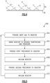
- FIG. 2 shows a method 100 of fabricating the CMC component 20.
- step 102 one or more preforms 26 are arranged in a reactor 28, as shown in Figure 3 .
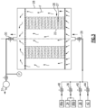
- the reactor 28 generally includes an inlet valve 29 to control inlets to the reactor 28 and an exhaust valve 30 to control exhaust from the reactor 28.
- a vacuum pump 31 controls the pressure in the reactor 28.
- the preforms 26 comprise fibers 22 and are generally porous.
- multiple preforms 26 are loaded to the reactor 28 and are stacked, with spacers 27 separating each preform 26 from adjacent preforms 26.
- preforms 26 can be arranged within reactor 28 in another way.
- only a single preform 26 is loaded to the reactor 28.
- a single preform 26 will be referred to in the foregoing description.
- a stoichiometric precursor layer 32 is infiltrated into the preform 26, as shown in Figure 4 .
- a stoichiometric material such as the stoichiometric precursor material, has a ratio of atomic constituents that is approximately the same as the ratio of constituents expressed in its chemical formula.
- SiC silicon carbide
- SiC has a ratio of silicon atoms to carbon atoms that is equal to approximately one.
- Silicon carbide with a ratio of silicon atoms to carbon atoms that is substantially equal to one exhibits improved temperature and oxidation resistance, as well as high thermal conductivity and high strength and creep resistance as compared to silicon carbide with a ratio of silicon atoms to carbon atoms that is substantially less than or greater than one. This is partially due to improved material uniformity. Additionally, if silicon carbide has a ratio of silicon atoms to carbon atoms greater than one, the silicon carbide has excess silicon and exhibits lowered melting temperature and lowered oxidation resistance.
- the silicon carbide has a ratio of silicon atoms to carbon atoms less than one, the silicon carbide has excess carbon and exhibits decreased temperature and oxidation resistance.
- the stoichiometric precursor layer 32 is silicon carbide, it should be understood that in other examples, the stoichiometric precursor layer 32 is another stoichiometric material.
- the stoichiometric precursor layer 32 is deposited into the one or more preforms 26 by an atomic layer deposition (ALD) process.
- ALD atomic layer deposition
- ALE atomic layer epitaxy
- An ALE process 200 is shown in Figure 5 .
- a gas 34 that is inert is provided to the reactor 28 by opening valve 36.
- the reactor 28 is then brought to a desired temperature T1 and a desired pressure P1.
- the desired temperature T1 and pressure P1 depend on selected and used precursors and the desired stoichiometric precursor layer 32. In one example, where the desired stoichiometric precursor layer 32 is silicon carbide, the desired temperature T1 is about 1832°F (1000°C) and the desired pressure P1 is about 0.3 torr (40 Pa).
- a first precursor 38 is provided to the reactor 28 by opening valve 40.
- valve 36 is closed to stop the flow of gas 34 into the reactor 28 and exhaust valve 30 is closed to keep the first precursor 38 in the reactor 28.
- step 206 is performed in approximately ten seconds or less.
- the first precursor infiltrates into and adsorbs on the surfaces of the preform 26.
- the first precursor is a silicon-containing precursor and the second precursor is a carbon-containing precursor.
- Example silicon-containing precursors are Cl 2 SiH 2 , SiH 4 , ClSiH 3 , and Si 2 H 6 .
- Example carbon-containing precursors are CH 4 (methane), C 2 H 6 (ethane), C 3 H 8 (propane), C 2 H 2 (acetylene), and C 2 H 4 (ethylene). However, if another stoichiometric precursor layer 32 is being formed, other precursors containing the elements of the desired stoichiometric precursor layer 32 would be used.
- valve 40 is closed to stop the flow of the first precursor 38 into the reactor 28.
- step 208 the reactor 28 is vacuumed by vacuum pump 31 by opening exhaust valve 30 to remove excess first precursor 38 from the reactor 28.
- step 208 is performed for approximately between 10 and 60 seconds.
- a second precursor 42 is provided to the reactor 28 by opening valve 44. At the same time, exhaust valve 30 is closed to keep the second precursor 42 in the reactor 28.
- the precursors 38, 42 form the stoichiometric precursor layer 32 (i.e., a layer 32 with a ratio of silicon atoms to carbon atoms of approximately one).
- the second precursor 42 is a carbon-containing precursor and infiltrates the preform 26 to form the silicon carbide, such that the ratio of silicon atoms to carbon atoms on the preform 26 is approximately one.
- step 210 is performed in approximately ten seconds or less.
- valve 44 is closed to stop the flow of the second precursor 42 into the reactor 28.
- silicon and carbon from the precursors 38, 42 form a silicon carbide stoichiometric precursor layer, as shown in Figure 4 .
- the first precursor 38 is the silicon-containing precursor and the second precursor 42 is the carbon-containing precursor.
- step 212 the reactor 28 is vacuumed by pump 31 by opening exhaust valve 30 to remove the second precursor 42 from the reactor 28.
- step 212 is performed for approximately between 10 and 60 seconds.
- Steps 206-212 can optionally be repeated one or more times to build up the stoichiometric precursor layer 32.
- the component 20 is densified by depositing matrix material 24 onto the stoichiometric precursor layer 32.
- the matrix material 24 is the same material as the stoichiometric precursor layer 32.
- the stoichiometric precursor layer 32 favors improved yield and deposition of a generally stoichiometric matrix material 24 in step 106. This is because reactions occurring at the surface of the preform 26 tend to mimic the existing surface chemistry of the stoichiometric precursor layer 32 to mitigate the stacking faults. Therefore, the matrix material 24 is generally stoichiometric and exhibits improved properties as described above.
- steps 104-106 are repeated one or more times. For instance, after partially densifying the preform 26 in step 106, the ratio of the constituents of the matrix material 24 is determined via x-ray or another type of spectroscopy in optional step 108. Then, the ratio of constituents is compared to the stoichiometric ratio in step 110. If the ratio differs from the stoichiometric ratio, another stoichiometric precursor layer 32 is infiltrated into the preform 26 as in step 104. The preform 26 is then densified again as in step 106. The further densification results in a generally stoichiometric matrix material 24 as described above.
- the densifying in step 106 is performed by a chemical vapor infiltration process 300, as shown schematically in Figure 6 .
- the reactor 28 is brought to a desired temperature T2 and pressure P2.
- T2 a temperature of approximately 1922°F (1050 °C) and a pressure P2 10 torr (1333.22 Pa).
- the temperature T2 in process 300 is greater than the temperature T1 in process 200
- the pressure P2 in process 300 is greater than the pressure P1 in process 200.
- step 304 one or more matrix material precursors 46a, 46b are provided to the reactor 28. Exhaust valve 30 remains open to allow for continuous flow of matrix material precursors 46a, 48b through the reactor 28, as shown by arrows F.
- example precursors 46a, 46b are methyltrichlorosilane (MTS) and hydrogen (H 2 ).
- MTS breaks down into gaseous CH 3 and SiCl 3 free radicals 50, as shown in Figure 7 , which adsorb onto the stoichiometric precursor layer 32 to react for the formation of silicon carbide deposit, in generally stoichiometric amounts to create a generally stoichiometric silicon carbide matrix material 24.
- Step 304 is performed until a desired density of the component 20 is achieved.
- MTS is provided to the reactor 28 by opening valve 48 and hydrogen is provided to the reactor 28 by valve 36, the same valve that controls flow of inert gas 34 to the reactor 28.
- a separate valve is used for hydrogen or another matrix material precursor.
- step 306 the reactor 28 is purged by closing valve 48 to stop the flow of matrix material precursor 46a into the reactor 28 and providing inert gas 34 to the reactor 28 via valve 36. In step 306, the reactor 28 is also cooled.
- steps 104 and 106 are described above as being performed in the same furnace, in another example, steps 104 and 106 can be performed in separate furnaces.
Landscapes
- Chemical & Material Sciences (AREA)
- Engineering & Computer Science (AREA)
- Ceramic Engineering (AREA)
- Organic Chemistry (AREA)
- Materials Engineering (AREA)
- Manufacturing & Machinery (AREA)
- Structural Engineering (AREA)
- Chemical Kinetics & Catalysis (AREA)
- General Chemical & Material Sciences (AREA)
- Mechanical Engineering (AREA)
- Metallurgy (AREA)
- Inorganic Chemistry (AREA)
- Ceramic Products (AREA)
- Chemical Vapour Deposition (AREA)
Abstract
Description
- This disclosure relates to a method of fabricating components, and in particular, ceramic matrix composite (CMC) components.
- CMC components typically comprise ceramic reinforcements, such as fibers, in a ceramic matrix phase. CMC components can withstand high temperatures and oxidative environments due to their material properties, high strength and creep resistance, high thermal conductivity, and relatively low weight. An example CMC component comprises silicon carbide reinforcement embedded in a silicon carbide matrix material.
- Various techniques are used to fabricate CMC components. For example, a preform comprising reinforcements is infiltrated with a matrix material. The composition of the matrix material affects the properties of the CMC component. In turn, the composition of the matrix material can be influenced by the method of depositing the matrix material onto the preform.
- A method for fabricating a component according to an example of the present invention includes the steps of depositing a stoichiometric precursor layer onto a preform, and densifying the preform by depositing a matrix material onto the stoichiometric precursor layer.
- In an embodiment according to the foregoing, the preform comprises silicon carbide fibers.
- In a further embodiment according to any of the foregoing embodiments, the stoichiometric precursor layer is silicon carbide, and the ratio of silicon to carbon in the stoichiometric precursor layer is approximately one.
- In a further embodiment according to any of the foregoing embodiments, the matrix material is silicon carbide and has a ratio of silicon atoms to carbon atoms, and the ratio is approximately one.
- In a further embodiment according to any of the foregoing embodiments, the step of depositing the stoichiometric precursor layer onto the preform is accomplished by an atomic layer deposition process.
- In a further embodiment according to any of the foregoing embodiments, the step of densifying the preform is accomplished by a chemical vapor infiltration process.
- In a further embodiment according to any of the foregoing embodiments, the matrix material comprises one or more constituents, and the method further comprises the steps of determining the ratio of the one or more constituents to one another, and comparing the ratio to the stoichiometric ratio of the matrix material.
- In a further embodiment according to any of the foregoing embodiments, the depositing step and the densifying step are performed in the same reactor.
- Another method of fabricating a component according to an example of the present invention includes the steps of arranging one or more preforms in a reactor, providing a silicon-containing precursor to the reactor such that the silicon-containing precursor adsorbs onto the one or more preforms, providing a carbon-containing precursor to the reactor such that the carbon-containing precursor reacts with the silicon-containing precursor to form a stoichiometric precursor layer, wherein the ratio of silicon atoms to carbon atoms in the stoichiometric precursor layer is approximately one, and providing at least one silicon carbide precursor to the reactor to densify the one or more preforms by depositing a silicon carbide matrix onto the stoichiometric precursor layer.
- In an embodiment according to any of the foregoing, the silicon carbide matrix has a ratio of silicon atoms to carbon atoms, and the ratio is approximately one.
- In a further embodiment according to any of the foregoing embodiments, the silicon-containing precursor includes one of Cl2SiH2, SiH4, ClSiH3, and Si2H6 and the carbon-containing precursor includes one of CH4 (methane), C2H6 (ethane), C3H8 (propane), C2H2 (acetylene), and C2H4 (ethylene).
- In a further embodiment according to any of the foregoing embodiments, the at least one silicon carbide precursor includes a first precursor and a second precursor, and the first precursor is methyltrichlorosilane (MTS) and the second precursor is hydrogen (H2).
- In a further embodiment according to any of the foregoing embodiments, the method further comprises the step of vacuuming the reactor after the step of providing the silicon-containing precursor to the reactor to remove excess silicon-containing precursor from the reactor.
- In a further embodiment according to any of the foregoing embodiments, the method further comprises the step of vacuuming the reactor after the step of providing the carbon-containing precursor to the reactor to remove excess carbon -containing precursor from the reactor.
- In a further embodiment according to any of the foregoing embodiments, wherein the reactor includes an exhaust valve, and wherein the exhaust valve is closed during the step of providing the silicon-containing precursor to the reactor and the step of providing the carbon-containing precursor to the reactor, and the exhaust valve is open during the step of providing at least one silicon-carbide precursor to the reactor.
- In a further embodiment according to any of the foregoing embodiments, the one or more preforms comprise silicon carbide fibers.
- In a further embodiment according to any of the foregoing embodiments, the silicon carbide fibers are coated with a boron nitride interfacial coating.
- In a further embodiment according to any of the foregoing embodiments, the silicon carbon fibers have a unidirectional orientation with respect to one another.
- In a further embodiment according to any of the foregoing embodiments, further including the step of determining the ratio of silicon atoms to carbon atoms in the silicon carbide matrix, and comparing the ratio to one.
- A ceramic matrix composite component according to an example of the present invention is formed by a process comprising the steps of depositing a stoichiometric precursor layer onto a preform and densifying the preform by depositing a matrix material onto the stoichiometric precursor layer.
-
-
Figure 1A schematically shows a ceramic matrix composite (CMC) component. -
Figure 1B schematically shows a close-up view of the CMC component. -
Figure 2 schematically shows a method of fabricating the CMC component. -
Figure 3 schematically shows a furnace for fabricating the CMC component. -
Figure 4 schematically shows a CMC component during fabrication. -
Figure 5 schematically shows a method depositing a stoichiometric precursor layer onto a preform. -
Figure 6 schematically shows a method of densifying a preform with a stoichiometric precursor layer to form a CMC component. -
Figure 7 schematically shows a CMC component during the densifying step. -
Figures 1A-1B schematically illustrate a ceramic matrix composite (CMC)component 20 for hot sections of gas turbine engines, which operate at temperatures greater than 2000°F (1093.33 °C). In the example ofFigure 1 , thecomponent 20 is a blade or vane for a turbine. However, in other examples,component 20 can be another part of a gas turbine engine, such as a combustor panel, a blade outer air seal, or another type of component. -
CMC component 20 includesceramic reinforcements 22, such as fibers, embedded in aceramic matrix material 24. In the example ofFigure 1 , thefibers 22 are arranged unidirectional with respect to one another. However, in other examples, thefibers 22 can have other orientations, or have random orientations. In a particular example,fibers 22 are silicon carbide fibers andmatrix 24 is silicon carbide as well. In some examples,fibers 22 include a coating, such as a boron nitride interfacial coating. -
Figure 2 shows amethod 100 of fabricating theCMC component 20. Instep 102, one ormore preforms 26 are arranged in areactor 28, as shown inFigure 3 . Thereactor 28 generally includes aninlet valve 29 to control inlets to thereactor 28 and an exhaust valve 30 to control exhaust from thereactor 28. Avacuum pump 31 controls the pressure in thereactor 28. - The
preforms 26 comprisefibers 22 and are generally porous. In the example ofFigure 3 ,multiple preforms 26 are loaded to thereactor 28 and are stacked, with spacers 27 separating eachpreform 26 fromadjacent preforms 26. In another example,preforms 26 can be arranged withinreactor 28 in another way. In yet another example, only asingle preform 26 is loaded to thereactor 28. For ease of reference, asingle preform 26 will be referred to in the foregoing description. - In
step 104, astoichiometric precursor layer 32 is infiltrated into thepreform 26, as shown inFigure 4 . A stoichiometric material, such as the stoichiometric precursor material, has a ratio of atomic constituents that is approximately the same as the ratio of constituents expressed in its chemical formula. For instance, stoichiometric silicon carbide (SiC) has a ratio of silicon atoms to carbon atoms that is equal to approximately one. Silicon carbide with a ratio of silicon atoms to carbon atoms that is substantially equal to one (i.e., "stoichiometric silicon carbide") exhibits improved temperature and oxidation resistance, as well as high thermal conductivity and high strength and creep resistance as compared to silicon carbide with a ratio of silicon atoms to carbon atoms that is substantially less than or greater than one. This is partially due to improved material uniformity. Additionally, if silicon carbide has a ratio of silicon atoms to carbon atoms greater than one, the silicon carbide has excess silicon and exhibits lowered melting temperature and lowered oxidation resistance. Likewise, if silicon carbide has a ratio of silicon atoms to carbon atoms less than one, the silicon carbide has excess carbon and exhibits decreased temperature and oxidation resistance. Though in this example, thestoichiometric precursor layer 32 is silicon carbide, it should be understood that in other examples, thestoichiometric precursor layer 32 is another stoichiometric material. - In one example, the
stoichiometric precursor layer 32 is deposited into the one ormore preforms 26 by an atomic layer deposition (ALD) process. In a particular example an atomic layer epitaxy (ALE) process is used. AnALE process 200 is shown inFigure 5 . Instep 202, agas 34 that is inert is provided to thereactor 28 by openingvalve 36. - In
step 204, thereactor 28 is then brought to a desired temperature T1 and a desired pressure P1. The desired temperature T1 and pressure P1 depend on selected and used precursors and the desiredstoichiometric precursor layer 32. In one example, where the desiredstoichiometric precursor layer 32 is silicon carbide, the desired temperature T1 is about 1832°F (1000°C) and the desired pressure P1 is about 0.3 torr (40 Pa). - In
step 206, afirst precursor 38 is provided to thereactor 28 by opening valve 40. At the same time,valve 36 is closed to stop the flow ofgas 34 into thereactor 28 and exhaust valve 30 is closed to keep thefirst precursor 38 in thereactor 28. In one example,step 206 is performed in approximately ten seconds or less. The first precursor infiltrates into and adsorbs on the surfaces of thepreform 26. For the silicon carbidestoichiometric precursor layer 32 discussed above, the first precursor is a silicon-containing precursor and the second precursor is a carbon-containing precursor. Example silicon-containing precursors are Cl2SiH2, SiH4, ClSiH3, and Si2H6. Example carbon-containing precursors are CH4 (methane), C2H6 (ethane), C3H8 (propane), C2H2 (acetylene), and C2H4 (ethylene). However, if anotherstoichiometric precursor layer 32 is being formed, other precursors containing the elements of the desiredstoichiometric precursor layer 32 would be used. At the end ofstep 206, valve 40 is closed to stop the flow of thefirst precursor 38 into thereactor 28. - In
step 208, thereactor 28 is vacuumed byvacuum pump 31 by opening exhaust valve 30 to remove excessfirst precursor 38 from thereactor 28. In one example,step 208 is performed for approximately between 10 and 60 seconds. - In
step 210, asecond precursor 42 is provided to thereactor 28 by opening valve 44. At the same time, exhaust valve 30 is closed to keep thesecond precursor 42 in thereactor 28. Duringstep 210, theprecursors layer 32 with a ratio of silicon atoms to carbon atoms of approximately one). In the example of a silicon carbidestoichiometric precursor layer 32, thesecond precursor 42 is a carbon-containing precursor and infiltrates thepreform 26 to form the silicon carbide, such that the ratio of silicon atoms to carbon atoms on thepreform 26 is approximately one. In one example,step 210 is performed in approximately ten seconds or less. At the end ofstep 210, valve 44 is closed to stop the flow of thesecond precursor 42 into thereactor 28. For example, silicon and carbon from theprecursors Figure 4 . In one example, thefirst precursor 38 is the silicon-containing precursor and thesecond precursor 42 is the carbon-containing precursor. - In
step 212, thereactor 28 is vacuumed bypump 31 by opening exhaust valve 30 to remove thesecond precursor 42 from thereactor 28. In one example,step 212 is performed for approximately between 10 and 60 seconds. - Steps 206-212 can optionally be repeated one or more times to build up the
stoichiometric precursor layer 32. - Referring again to
Figure 2 , instep 106, thecomponent 20 is densified by depositingmatrix material 24 onto thestoichiometric precursor layer 32. Thematrix material 24 is the same material as thestoichiometric precursor layer 32. Thestoichiometric precursor layer 32 favors improved yield and deposition of a generallystoichiometric matrix material 24 instep 106. This is because reactions occurring at the surface of thepreform 26 tend to mimic the existing surface chemistry of thestoichiometric precursor layer 32 to mitigate the stacking faults. Therefore, thematrix material 24 is generally stoichiometric and exhibits improved properties as described above. - In one example, steps 104-106 are repeated one or more times. For instance, after partially densifying the
preform 26 instep 106, the ratio of the constituents of thematrix material 24 is determined via x-ray or another type of spectroscopy inoptional step 108. Then, the ratio of constituents is compared to the stoichiometric ratio instep 110. If the ratio differs from the stoichiometric ratio, anotherstoichiometric precursor layer 32 is infiltrated into thepreform 26 as instep 104. Thepreform 26 is then densified again as instep 106. The further densification results in a generallystoichiometric matrix material 24 as described above. - In one example, the densifying in
step 106 is performed by a chemicalvapor infiltration process 300, as shown schematically inFigure 6 . - In
step 302, thereactor 28 is brought to a desired temperature T2 and pressure P2. For example, for the deposition of siliconcarbide matrix material 24 with precursors methyltrichlorosilane (MTS) and hydrogen (H2), as will be discussed below, the reactor is brought to a temperature T2 of approximately 1922°F (1050 °C) and a pressure P2 10 torr (1333.22 Pa). In another example, the temperature T2 inprocess 300 is greater than the temperature T1 inprocess 200, and the pressure P2 inprocess 300 is greater than the pressure P1 inprocess 200. - In
step 304, one or morematrix material precursors reactor 28. Exhaust valve 30 remains open to allow for continuous flow ofmatrix material precursors 46a, 48b through thereactor 28, as shown by arrows F. For a siliconcarbide matrix material 24,example precursors step 304, MTS breaks down into gaseous CH3 and SiCl3free radicals 50, as shown inFigure 7 , which adsorb onto thestoichiometric precursor layer 32 to react for the formation of silicon carbide deposit, in generally stoichiometric amounts to create a generally stoichiometric siliconcarbide matrix material 24. Step 304 is performed until a desired density of thecomponent 20 is achieved. - In one example, MTS is provided to the
reactor 28 by openingvalve 48 and hydrogen is provided to thereactor 28 byvalve 36, the same valve that controls flow ofinert gas 34 to thereactor 28. In another example, a separate valve is used for hydrogen or another matrix material precursor. - In
step 306, thereactor 28 is purged by closingvalve 48 to stop the flow ofmatrix material precursor 46a into thereactor 28 and providinginert gas 34 to thereactor 28 viavalve 36. Instep 306, thereactor 28 is also cooled. - Though
steps - Furthermore, the foregoing description shall be interpreted as illustrative and not in any limiting sense. A worker of ordinary skill in the art would understand that certain modifications could come within the scope of this disclosure. For these reasons, the following claims should be studied to determine the true scope and content of this disclosure.
Claims (15)
- A method of fabricating a component (20), comprising the steps of:depositing a stoichiometric precursor layer (32) onto a preform (26); anddensifying the preform (26) by depositing a matrix material (24) onto the stoichiometric precursor layer (32), wherein the matrix material (24) is the same material as the stoichiometric precursor layer (32).
- The method of claim 1, wherein the preform (26) comprises silicon carbide fibers (22), wherein, optionally the silicon carbide fibers (22) have a unidirectional orientation with respect to one another.
- The method of claim 1 or 2, wherein the stoichiometric precursor layer (32) is silicon carbide, and the ratio of silicon to carbon in the stoichiometric precursor layer (32) is approximately one.
- The method of any preceding claim, wherein the depositing step and the densifying step are performed in the same reactor (28).
- The method of any preceding claim, wherein:the step of depositing the stoichiometric precursor layer (32) onto the preform (26) is accomplished by an atomic layer deposition process; and/orthe step of densifying the preform (26) is accomplished by a chemical vapor infiltration process.
- The method of any preceding claim, wherein the matrix material (24) comprises one or more constituents, and the method further comprises the steps of:determining the ratio of the one or more constituents to one another; andcomparing the ratio to the stoichiometric ratio of the matrix material (24).
- The method of any preceding claim, further comprising repeating the depositing step and the densifying step.
- The method of any preceding claim, wherein, during the densifying step, the matrix material (24) mimics the surface chemistry of the stoichiometric precursor layer (32).
- The method of any preceding claim, wherein the depositing step is performed at a first temperature (T1) and a first pressure (P1), and wherein the densifying step is performed at a second temperature (T2) and a second pressure (P2), wherein the second temperature (T2) is greater than the first temperature (T1) and the second pressure (P2) is greater than the first pressure (P1).
- A method of fabricating a component (20), the method comprising:arranging one or more preforms (26) in a reactor (28);providing a silicon-containing precursor (38) to the reactor (28) such that the silicon-containing precursor (38) adsorbs onto the one or more preforms (26);providing a carbon-containing precursor (42) to the reactor (28) such that the carbon-containing precursor (42) reacts with the silicon-containing precursor (38) to form a stoichiometric precursor layer (32), wherein the ratio of silicon atoms to carbon atoms in the stoichiometric precursor layer (32) is approximately one; andproviding at least one silicon carbide precursor (46a, 46b) to the reactor to densify the one or more preforms (26) by depositing a silicon carbide matrix (24) onto the stoichiometric precursor layer (32).
- The method of claim 10, wherein the silicon carbide matrix (24) has a ratio of silicon atoms to carbon atoms of approximately one; and/or wherein the silicon-containing precursor (38) includes:one of Cl2SiH2, SiH4, ClSiH3, and Si2H6 and the carbon-containing precursor (42) includes one of CH4 (methane), C2H6 (ethane), C3H8 (propane), C2H2 (acetylene), and C2H4 (ethylene); and/ora first precursor (46a) and a second precursor (46b), and the first precursor (46a) is methyltrichlorosilane (MTS) and the second precursor (46b) is hydrogen (H2).
- The method of claim 10 or 11, further comprising the step of vacuuming the reactor (28) after the step of providing the silicon-containing precursor (38) or the carbon-containing precursor (42) to the reactor (28) to remove excess silicon-containing precursor (38) or carbon-containing precursor (42) from the reactor (28).
- The method of any of claims 10 to 12, wherein the reactor (28) includes an exhaust valve (30), and the exhaust valve (30) is closed during the step of providing the silicon-containing precursor (38) to the reactor (28) and the step of providing the carbon-containing precursor (42) to the reactor (28), and the exhaust valve (30) is open during the step of providing at least one silicon-carbide precursor (46a, 46b) to the reactor (28).
- The method of any of claims 10 to 13, wherein the one or more preforms (26) comprise silicon carbide fibers (22), and wherein, optionally:the silicon carbide fibers (22) are coated with a boron nitride interfacial coating; and/orthe silicon carbon fibers (22) have a unidirectional orientation with respect to one another.
- The method of any of claims 10 to 14, further comprising determining the ratio of silicon atoms to carbon atoms in the silicon carbide matrix (24), and comparing the ratio to one.
Applications Claiming Priority (2)
| Application Number | Priority Date | Filing Date | Title |
|---|---|---|---|
| US15/687,625 US10801108B2 (en) | 2017-08-28 | 2017-08-28 | Method for fabricating ceramic matrix composite components |
| EP18191322.9A EP3450416B1 (en) | 2017-08-28 | 2018-08-28 | Method for fabricating ceramic matrix composite components |
Related Parent Applications (2)
| Application Number | Title | Priority Date | Filing Date |
|---|---|---|---|
| EP18191322.9A Division-Into EP3450416B1 (en) | 2017-08-28 | 2018-08-28 | Method for fabricating ceramic matrix composite components |
| EP18191322.9A Division EP3450416B1 (en) | 2017-08-28 | 2018-08-28 | Method for fabricating ceramic matrix composite components |
Publications (2)
| Publication Number | Publication Date |
|---|---|
| EP4242193A2 true EP4242193A2 (en) | 2023-09-13 |
| EP4242193A3 EP4242193A3 (en) | 2023-11-29 |
Family
ID=63442545
Family Applications (2)
| Application Number | Title | Priority Date | Filing Date |
|---|---|---|---|
| EP18191322.9A Active EP3450416B1 (en) | 2017-08-28 | 2018-08-28 | Method for fabricating ceramic matrix composite components |
| EP23185025.6A Pending EP4242193A3 (en) | 2017-08-28 | 2018-08-28 | Method for fabricating ceramic matrix composite components |
Family Applications Before (1)
| Application Number | Title | Priority Date | Filing Date |
|---|---|---|---|
| EP18191322.9A Active EP3450416B1 (en) | 2017-08-28 | 2018-08-28 | Method for fabricating ceramic matrix composite components |
Country Status (2)
| Country | Link |
|---|---|
| US (3) | US10801108B2 (en) |
| EP (2) | EP3450416B1 (en) |
Families Citing this family (3)
| Publication number | Priority date | Publication date | Assignee | Title |
|---|---|---|---|---|
| US10801108B2 (en) * | 2017-08-28 | 2020-10-13 | Raytheon Technologies Corporation | Method for fabricating ceramic matrix composite components |
| US12269779B2 (en) | 2019-01-04 | 2025-04-08 | Rtx Corporation | Method for producing a ceramic matrix composite component |
| US12583798B2 (en) * | 2023-02-13 | 2026-03-24 | Rtx Corporation | Atomic layer deposition method enhancing the nucleation and crystallinity of a boron nitride interface coating on a silicon carbide fiber |
Family Cites Families (30)
| Publication number | Priority date | Publication date | Assignee | Title |
|---|---|---|---|---|
| JP3182212B2 (en) * | 1991-05-21 | 2001-07-03 | アブコウ・コーポレイション | Method for producing a densified porous billet and method for densifying a porous preform |
| US5354527A (en) * | 1992-02-21 | 1994-10-11 | The Carborundum Company | Process for making silicon carbide ceramic fibers |
| US6743393B1 (en) | 1998-06-17 | 2004-06-01 | Coi Ceramics, Inc. | Method for producing ceramic matrix composites |
| US7297368B2 (en) * | 2003-04-15 | 2007-11-20 | Ultramet | Method of making carbon fiber-carbon matrix reinforced ceramic composites |
| US20050276961A1 (en) * | 2003-08-04 | 2005-12-15 | Sherwood Walter J | Materials and methods for making ceramic matrix composites |
| US20060035024A1 (en) * | 2004-08-11 | 2006-02-16 | General Electric Company | Processing of Sic/Sic ceramic matrix composites by use of colloidal carbon black |
| US20060163773A1 (en) * | 2005-01-24 | 2006-07-27 | General Electric Company | Method for performing silicon melt infiltration of ceramic matrix composites |
| US7549840B2 (en) * | 2005-06-17 | 2009-06-23 | General Electric Company | Through thickness reinforcement of SiC/SiC CMC's through in-situ matrix plugs manufactured using fugitive fibers |
| FI122323B (en) * | 2006-06-22 | 2011-11-30 | Beneq Oy | Process for preparing a fiber preform |
| US7888248B2 (en) | 2007-07-13 | 2011-02-15 | Northrop Grumman Systems Corporation | Method of producing large area SiC substrates |
| US20100151676A1 (en) * | 2008-12-16 | 2010-06-17 | Applied Materials, Inc. | Densification process for titanium nitride layer for submicron applications |
| US20100284810A1 (en) * | 2009-05-07 | 2010-11-11 | General Electric Company | Process for inhibiting delamination in a bend of a continuous fiber-reinforced composite article |
| US20110071014A1 (en) * | 2009-09-24 | 2011-03-24 | United Technologies Corporation | Hybred polymer cvi composites |
| FR2950622B1 (en) * | 2009-09-28 | 2011-10-21 | Snecma Propulsion Solide | PIECE OF COMPOSITE MATERIAL WITH CERAMIC MATRIX AND METHOD FOR MANUFACTURING THE SAME |
| FR2957093B1 (en) * | 2010-03-02 | 2012-03-23 | Snecma | FIBROUS PREFORM FOR A TURBINE RING SECTOR AND METHOD FOR MANUFACTURING SAME |
| CN102534491B (en) * | 2011-10-19 | 2014-08-27 | 深圳市三海光电技术有限公司 | Preparation device and preparation method for absorbing layer of high conversion efficiency CIGS (Copper Indium Gallium Selenium) thin film solar cell |
| US20130167374A1 (en) | 2011-12-29 | 2013-07-04 | General Electric Company | Process of producing ceramic matrix composites and ceramic matrix composites formed thereby |
| US9050769B2 (en) * | 2012-04-13 | 2015-06-09 | General Electric Company | Pre-form ceramic matrix composite cavity and method of forming and method of forming a ceramic matrix composite component |
| WO2014159556A2 (en) * | 2013-03-14 | 2014-10-02 | Rolls-Royce Corporation | Environmental barrier fiber coating |
| US9650303B2 (en) * | 2013-03-15 | 2017-05-16 | Rolls-Royce Corporation | Silicon carbide ceramic matrix composites |
| US9512044B2 (en) * | 2013-03-15 | 2016-12-06 | Rolls-Royce Corporation | Ceramic matrix composites and methods for producing ceramic matrix composites |
| US9726025B2 (en) * | 2013-03-15 | 2017-08-08 | Rolls-Royce Corporation | Ceramic matrix composite |
| WO2015041823A1 (en) * | 2013-09-20 | 2015-03-26 | General Electric Company | Ceramic matrix composites made by chemical vapor infiltration and methods of manufacture thereof |
| EP2933353B1 (en) | 2014-04-17 | 2017-12-20 | Safran Ceramics | Method for producing fiber-reinforced composites |
| US10233126B2 (en) * | 2015-08-12 | 2019-03-19 | Rolls-Royce Corporation | Forming a ceramic matrix composite having a silicide layer |
| US10465533B2 (en) * | 2015-10-08 | 2019-11-05 | General Electric Company | Ceramic matrix composite component and process of producing a ceramic matrix composite component |
| RU2720579C1 (en) * | 2016-08-08 | 2020-05-12 | Дженерал Атомикс | Developed sic-sic composite and monolithic layered sic structures |
| CN107011620A (en) * | 2017-05-17 | 2017-08-04 | 郴州金通信息科技有限公司 | One kind mixes graphene nanometer sheet 3D printing modified ABS material and preparation method thereof |
| US10801108B2 (en) * | 2017-08-28 | 2020-10-13 | Raytheon Technologies Corporation | Method for fabricating ceramic matrix composite components |
| US10829419B2 (en) * | 2017-11-27 | 2020-11-10 | United Technologies Corporation | Method of densifying a ceramic matrix composite using a filled tackifier |
-
2017
- 2017-08-28 US US15/687,625 patent/US10801108B2/en active Active
-
2018
- 2018-08-28 EP EP18191322.9A patent/EP3450416B1/en active Active
- 2018-08-28 EP EP23185025.6A patent/EP4242193A3/en active Pending
-
2020
- 2020-09-18 US US17/025,544 patent/US11597686B2/en active Active
-
2023
- 2023-03-06 US US18/117,825 patent/US20230219858A1/en active Pending
Also Published As
| Publication number | Publication date |
|---|---|
| US11597686B2 (en) | 2023-03-07 |
| EP3450416A1 (en) | 2019-03-06 |
| US20230219858A1 (en) | 2023-07-13 |
| US20190062913A1 (en) | 2019-02-28 |
| EP3450416B1 (en) | 2023-08-23 |
| EP4242193A3 (en) | 2023-11-29 |
| US20210002766A1 (en) | 2021-01-07 |
| US10801108B2 (en) | 2020-10-13 |
Similar Documents
| Publication | Publication Date | Title |
|---|---|---|
| US20230219858A1 (en) | Method for fabricating ceramic matrix composite components | |
| EP3061740B1 (en) | Ceramic matrix composite structures with controlled microstructures fabricated using chemical vapor infiltration (cvi) | |
| US9493873B2 (en) | Method for preparing a coating for protecting a part against oxidation | |
| US6896968B2 (en) | Coatings and method for protecting carbon-containing components from oxidation | |
| US10906842B2 (en) | Method of processing a ceramic matrix composite (CMC) component | |
| US12325670B2 (en) | Doped silicon carbide ceramic matrix composite | |
| US20110071014A1 (en) | Hybred polymer cvi composites | |
| US11046620B2 (en) | Method of processing a ceramic matrix composite (CMC) component | |
| US20160251272A1 (en) | Laminate structure fabricated using chemical vapor infiltration (cvi) | |
| US20200024197A1 (en) | Method of forming in-situ boron nitride for ceramic matrix composite environmental protection | |
| EP3650424A1 (en) | Accelerated cvi densification of cmc through infiltration | |
| CA2913266A1 (en) | Bond layer for silicon-containing substrates | |
| EP3957619A1 (en) | Method of making a ceramic matrix composite that exhibits chemical resistance | |
| JP7752004B2 (en) | Method for making ceramic matrix composites that exhibit moisture and environmental resistance | |
| US10752556B2 (en) | Method of processing a ceramic matrix composite (CMC) component | |
| US10233126B2 (en) | Forming a ceramic matrix composite having a silicide layer | |
| US11198934B2 (en) | Method of chemical vapor infiltration or deposition | |
| EP3677563B1 (en) | Method for producing a ceramic matrix composite component | |
| EP2933353A1 (en) | Use of silicon and carbon precursors for producing fiber-reinforced composites | |
| CN105503270A (en) | Method for preparing SiC coating | |
| US11655194B2 (en) | Ceramic composites with an intermediate layer having a carbon sink material for high temperature applications | |
| US20240279128A1 (en) | Methods for Joining Composite Components to Form a Unitary Composite Component | |
| JPH09201896A (en) | Heat and oxidation resistant carbon materials | |
| JP2025080034A (en) | BN-coated ceramic fiber, ceramic-based composite material including the same, and method for manufacturing BN-coated ceramic fiber |
Legal Events
| Date | Code | Title | Description |
|---|---|---|---|
| PUAI | Public reference made under article 153(3) epc to a published international application that has entered the european phase |
Free format text: ORIGINAL CODE: 0009012 |
|
| STAA | Information on the status of an ep patent application or granted ep patent |
Free format text: STATUS: THE APPLICATION HAS BEEN PUBLISHED |
|
| AC | Divisional application: reference to earlier application |
Ref document number: 3450416 Country of ref document: EP Kind code of ref document: P |
|
| AK | Designated contracting states |
Kind code of ref document: A2 Designated state(s): AL AT BE BG CH CY CZ DE DK EE ES FI FR GB GR HR HU IE IS IT LI LT LU LV MC MK MT NL NO PL PT RO RS SE SI SK SM TR |
|
| REG | Reference to a national code |
Ref country code: DE Ref legal event code: R079 Free format text: PREVIOUS MAIN CLASS: C04B0035800000 Ipc: C04B0035565000 |
|
| PUAL | Search report despatched |
Free format text: ORIGINAL CODE: 0009013 |
|
| RAP3 | Party data changed (applicant data changed or rights of an application transferred) |
Owner name: RTX CORPORATION |
|
| AK | Designated contracting states |
Kind code of ref document: A3 Designated state(s): AL AT BE BG CH CY CZ DE DK EE ES FI FR GB GR HR HU IE IS IT LI LT LU LV MC MK MT NL NO PL PT RO RS SE SI SK SM TR |
|
| RIC1 | Information provided on ipc code assigned before grant |
Ipc: C04B 35/80 20060101ALI20231020BHEP Ipc: C04B 35/628 20060101ALI20231020BHEP Ipc: C04B 35/565 20060101AFI20231020BHEP |
|
| STAA | Information on the status of an ep patent application or granted ep patent |
Free format text: STATUS: REQUEST FOR EXAMINATION WAS MADE |
|
| 17P | Request for examination filed |
Effective date: 20240524 |
|
| RBV | Designated contracting states (corrected) |
Designated state(s): AL AT BE BG CH CY CZ DE DK EE ES FI FR GB GR HR HU IE IS IT LI LT LU LV MC MK MT NL NO PL PT RO RS SE SI SK SM TR |