EP4242092A1 - Scooter type electric vehicle - Google Patents
Scooter type electric vehicle Download PDFInfo
- Publication number
- EP4242092A1 EP4242092A1 EP23158209.9A EP23158209A EP4242092A1 EP 4242092 A1 EP4242092 A1 EP 4242092A1 EP 23158209 A EP23158209 A EP 23158209A EP 4242092 A1 EP4242092 A1 EP 4242092A1
- Authority
- EP
- European Patent Office
- Prior art keywords
- vehicle
- side wall
- electrical component
- scooter type
- electric vehicle
- Prior art date
- Legal status (The legal status is an assumption and is not a legal conclusion. Google has not performed a legal analysis and makes no representation as to the accuracy of the status listed.)
- Withdrawn
Links
Images


Classifications
-
- B—PERFORMING OPERATIONS; TRANSPORTING
- B62—LAND VEHICLES FOR TRAVELLING OTHERWISE THAN ON RAILS
- B62J—CYCLE SADDLES OR SEATS; AUXILIARY DEVICES OR ACCESSORIES SPECIALLY ADAPTED TO CYCLES AND NOT OTHERWISE PROVIDED FOR, e.g. ARTICLE CARRIERS OR CYCLE PROTECTORS
- B62J9/00—Containers specially adapted for cycles, e.g. panniers or saddle bags
- B62J9/10—Containers specially adapted for cycles, e.g. panniers or saddle bags integrated with the cycle
- B62J9/14—Containers specially adapted for cycles, e.g. panniers or saddle bags integrated with the cycle under the saddle
-
- B—PERFORMING OPERATIONS; TRANSPORTING
- B62—LAND VEHICLES FOR TRAVELLING OTHERWISE THAN ON RAILS
- B62J—CYCLE SADDLES OR SEATS; AUXILIARY DEVICES OR ACCESSORIES SPECIALLY ADAPTED TO CYCLES AND NOT OTHERWISE PROVIDED FOR, e.g. ARTICLE CARRIERS OR CYCLE PROTECTORS
- B62J43/00—Arrangements of batteries
- B62J43/20—Arrangements of batteries characterised by the mounting
-
- B—PERFORMING OPERATIONS; TRANSPORTING
- B62—LAND VEHICLES FOR TRAVELLING OTHERWISE THAN ON RAILS
- B62M—RIDER PROPULSION OF WHEELED VEHICLES OR SLEDGES; POWERED PROPULSION OF SLEDGES OR SINGLE-TRACK CYCLES; TRANSMISSIONS SPECIALLY ADAPTED FOR SUCH VEHICLES
- B62M7/00—Motorcycles characterised by position of motor or engine
- B62M7/12—Motorcycles characterised by position of motor or engine with the engine beside or within the driven wheel
-
- B—PERFORMING OPERATIONS; TRANSPORTING
- B60—VEHICLES IN GENERAL
- B60K—ARRANGEMENT OR MOUNTING OF PROPULSION UNITS OR OF TRANSMISSIONS IN VEHICLES; ARRANGEMENT OR MOUNTING OF PLURAL DIVERSE PRIME-MOVERS IN VEHICLES; AUXILIARY DRIVES FOR VEHICLES; INSTRUMENTATION OR DASHBOARDS FOR VEHICLES; ARRANGEMENTS IN CONNECTION WITH COOLING, AIR INTAKE, GAS EXHAUST OR FUEL SUPPLY OF PROPULSION UNITS IN VEHICLES
- B60K1/00—Arrangement or mounting of electrical propulsion units
- B60K1/04—Arrangement or mounting of electrical propulsion units of the electric storage means for propulsion
-
- B—PERFORMING OPERATIONS; TRANSPORTING
- B60—VEHICLES IN GENERAL
- B60K—ARRANGEMENT OR MOUNTING OF PROPULSION UNITS OR OF TRANSMISSIONS IN VEHICLES; ARRANGEMENT OR MOUNTING OF PLURAL DIVERSE PRIME-MOVERS IN VEHICLES; AUXILIARY DRIVES FOR VEHICLES; INSTRUMENTATION OR DASHBOARDS FOR VEHICLES; ARRANGEMENTS IN CONNECTION WITH COOLING, AIR INTAKE, GAS EXHAUST OR FUEL SUPPLY OF PROPULSION UNITS IN VEHICLES
- B60K7/00—Disposition of motor in, or adjacent to, traction wheel
- B60K7/0007—Disposition of motor in, or adjacent to, traction wheel the motor being electric
-
- B—PERFORMING OPERATIONS; TRANSPORTING
- B62—LAND VEHICLES FOR TRAVELLING OTHERWISE THAN ON RAILS
- B62J—CYCLE SADDLES OR SEATS; AUXILIARY DEVICES OR ACCESSORIES SPECIALLY ADAPTED TO CYCLES AND NOT OTHERWISE PROVIDED FOR, e.g. ARTICLE CARRIERS OR CYCLE PROTECTORS
- B62J43/00—Arrangements of batteries
- B62J43/10—Arrangements of batteries for propulsion
- B62J43/16—Arrangements of batteries for propulsion on motorcycles or the like
-
- B—PERFORMING OPERATIONS; TRANSPORTING
- B62—LAND VEHICLES FOR TRAVELLING OTHERWISE THAN ON RAILS
- B62K—CYCLES; CYCLE FRAMES; CYCLE STEERING DEVICES; RIDER-OPERATED TERMINAL CONTROLS SPECIALLY ADAPTED FOR CYCLES; CYCLE AXLE SUSPENSIONS; CYCLE SIDECARS, FORECARS, OR THE LIKE
- B62K11/00—Motorcycles, engine-assisted cycles or motor scooters with one or two wheels
- B62K11/02—Frames
-
- B—PERFORMING OPERATIONS; TRANSPORTING
- B60—VEHICLES IN GENERAL
- B60K—ARRANGEMENT OR MOUNTING OF PROPULSION UNITS OR OF TRANSMISSIONS IN VEHICLES; ARRANGEMENT OR MOUNTING OF PLURAL DIVERSE PRIME-MOVERS IN VEHICLES; AUXILIARY DRIVES FOR VEHICLES; INSTRUMENTATION OR DASHBOARDS FOR VEHICLES; ARRANGEMENTS IN CONNECTION WITH COOLING, AIR INTAKE, GAS EXHAUST OR FUEL SUPPLY OF PROPULSION UNITS IN VEHICLES
- B60K1/00—Arrangement or mounting of electrical propulsion units
- B60K1/04—Arrangement or mounting of electrical propulsion units of the electric storage means for propulsion
- B60K2001/0405—Arrangement or mounting of electrical propulsion units of the electric storage means for propulsion characterised by their position
- B60K2001/0422—Arrangement under the front seats
-
- B—PERFORMING OPERATIONS; TRANSPORTING
- B60—VEHICLES IN GENERAL
- B60L—PROPULSION OF ELECTRICALLY-PROPELLED VEHICLES; SUPPLYING ELECTRIC POWER FOR AUXILIARY EQUIPMENT OF ELECTRICALLY-PROPELLED VEHICLES; ELECTRODYNAMIC BRAKE SYSTEMS FOR VEHICLES IN GENERAL; MAGNETIC SUSPENSION OR LEVITATION FOR VEHICLES; MONITORING OPERATING VARIABLES OF ELECTRICALLY-PROPELLED VEHICLES; ELECTRIC SAFETY DEVICES FOR ELECTRICALLY-PROPELLED VEHICLES
- B60L2210/00—Converter types
- B60L2210/10—DC to DC converters
-
- B—PERFORMING OPERATIONS; TRANSPORTING
- B62—LAND VEHICLES FOR TRAVELLING OTHERWISE THAN ON RAILS
- B62K—CYCLES; CYCLE FRAMES; CYCLE STEERING DEVICES; RIDER-OPERATED TERMINAL CONTROLS SPECIALLY ADAPTED FOR CYCLES; CYCLE AXLE SUSPENSIONS; CYCLE SIDECARS, FORECARS, OR THE LIKE
- B62K2202/00—Motorised scooters
-
- B—PERFORMING OPERATIONS; TRANSPORTING
- B62—LAND VEHICLES FOR TRAVELLING OTHERWISE THAN ON RAILS
- B62K—CYCLES; CYCLE FRAMES; CYCLE STEERING DEVICES; RIDER-OPERATED TERMINAL CONTROLS SPECIALLY ADAPTED FOR CYCLES; CYCLE AXLE SUSPENSIONS; CYCLE SIDECARS, FORECARS, OR THE LIKE
- B62K2204/00—Adaptations for driving cycles by electric motor
-
- Y—GENERAL TAGGING OF NEW TECHNOLOGICAL DEVELOPMENTS; GENERAL TAGGING OF CROSS-SECTIONAL TECHNOLOGIES SPANNING OVER SEVERAL SECTIONS OF THE IPC; TECHNICAL SUBJECTS COVERED BY FORMER USPC CROSS-REFERENCE ART COLLECTIONS [XRACs] AND DIGESTS
- Y02—TECHNOLOGIES OR APPLICATIONS FOR MITIGATION OR ADAPTATION AGAINST CLIMATE CHANGE
- Y02T—CLIMATE CHANGE MITIGATION TECHNOLOGIES RELATED TO TRANSPORTATION
- Y02T10/00—Road transport of goods or passengers
- Y02T10/60—Other road transportation technologies with climate change mitigation effect
- Y02T10/70—Energy storage systems for electromobility, e.g. batteries
Definitions
- the present invention relates to scooter type electric vehicles that are powered by an electric motor to travel.
- scooter type two-wheeled electric vehicles that have an electric motor as a source of power for traveling (see, for example, JP 2000-253591 A ).
- the electric motor operates with electric power supplied from a battery mounted on the vehicle to rotate.
- the rotation of the electric motor is transmitted to a wheel, thereby allowing the vehicle to travel.
- a scooter type two-wheeled electric vehicle is equipped with various parts including electrical components.
- a number of parts need to be arranged within a limited space in the body of the vehicle, and therefore, it is not easy to allocate a space for arrangement of electrical components.
- a scooter type electric vehicle includes: a front wheel and a rear wheel; an electric motor that produces rotation according to power supplied from a battery, and drives at least one of the front wheel and the rear wheel; a floorboard that is located between the front wheel and the rear wheel, and on which a rider's feet are placed; a seat that is located behind and diagonally above the floorboard, and on which the rider sits; a container box that is located below the seat, and has a first front wall, a first left side wall, and a first right side wall; a cover that has a second front wall covering the first front wall, a second left side wall covering the first left side wall, and a second right side wall covering the first right side wall; and a first electrical component that is located between the first front wall and the second front wall, a second electrical component that is located between the first left side wall and the second left side wall, and a third electrical component that is located between the first right side wall and the second right side wall.
- a plurality of electrical components are arranged at distributed positions that are a position between the first front wall of the container box and the second front wall of the cover, a position between the first left side wall of the container box and the second left side wall of the cover, and a position between the first right side wall of the container box and the second right side wall of the cover. Therefore, it is not necessary to allocate, in the vehicle, a large space for arranging a plurality of electrical components all in one place. By utilizing spaces between the container box and the cover, a slim volume can accommodate all of the electrical components.
- a plurality of electrical components are distributed, but are arranged around the container box, so that a distance between each electrical component is relatively short. Therefore, the length of an electrical cable connecting between each electrical component can be reduced. For example, as a large current flows through an electrical component that is provided on an electrical path between the battery and the electric motor, an electrical cable connected to such electrical components has a large cross-sectional area.
- the lengths of electrical cables having a large cross-sectional area can be reduced, resulting in a reduction in a space for arranging the electrical cables.
- the reduction in the length of an electrical cable having a large cross-sectional area can lead to a reduction in weight and cost.
- the electrical components are located around the container box, i.e., at a relatively high position, the electrical components are less likely to get wet even if water on the road surface enters the vehicle.
- the battery may be located in the container box.
- the electrical cable As a large current flows through an electrical cable that connects the battery and an electrical component, the electrical cable has a large cross-sectional area.
- the lengths of electrical cables having a large cross-sectional area that connect the battery and the electrical components can be reduced.
- the battery may be removably attached to the scooter type electric vehicle.
- the battery can be charged by being connected to an external charger with the battery removed from the vehicle. For example, even when no charging equipment is provided in a parking garage, the battery can be charged.
- the first electrical component, the second electrical component, and the third electrical component may have different functions.
- the first electrical component, the second electrical component, and the third electrical component may each be any of a control device that controls an operation of the scooter type electric vehicle, a converter that changes the magnitude of the output voltage of the battery and outputs the resultant voltage, a battery switcher that switches batteries for use, a positioning device that detects a location of the scooter type electric vehicle in a geographic coordinate system, and a communication device that performs data communication between the scooter type electric vehicle and an external device.
- the first electrical component located between the first front wall and the second front wall may be thicker than the second electrical component and the third electrical component.
- the scooter type electric vehicle may further include a frame that extends through a position between the first left side wall and the second left side wall and a position between the first right side wall and the second right side wall. At least one of the second electrical component and the third electrical component may be located inward of the frame in a width direction of the scooter type electric vehicle.
- the scooter type electric vehicle may further include a frame that extends through a position between the first left side wall and the second left side wall and a position between the first right side wall and the second right side wall. At least one of the second electrical component and the third electrical component may be located on the frame.
- the second electrical component and the third electrical component can be easily located between the container box and the cover.
- At least one of the second electrical component and the third electrical component may be located at or behind a center portion of the container box in a forward/rearward direction of the scooter type electric vehicle.
- a front left diagonal portion and a front right diagonal portion of the cover covering the container box can be slimmed, and therefore, a portion for the rider's feet of the scooter type electric vehicle can have a simple design.
- the scooter type electric vehicle may further include a frame that extends through a position between the first left side wall and the second left side wall and a position between the first right side wall and the second right side wall.
- the frame is shaped to extend rearward and diagonally upward at a position lateral to the container box.
- At least one of the second electrical component and the third electrical component may be located on the frame at or behind the center portion of the container box in a forward/rearward direction of the scooter type electric vehicle.
- a front left diagonal portion and a front right diagonal portion of the cover covering the container box can be slimmed, and therefore, a portion for the rider's feet of the scooter type electric vehicle can have a simple design.
- the second electrical component and the third electrical component can be located at a higher position. Therefore, the second electrical component and the third electrical component are less likely to get wet even if water on the road surface enters the vehicle.
- the scooter type electric vehicle may further include a swingarm that supports the rear wheel.
- the electric motor may be provided on the swingarm.
- the scooter type electric vehicle may be a scooter type two-wheeled electric vehicle.
- a number of parts need to be arranged within a limited space in the vehicle, and therefore, a limitation is imposed on arrangement of the parts.
- a plurality of electrical components are arranged at distributed positions that are a position between the first front wall of the container box and the second front wall of the cover, a position between the first left side wall of the container box and the second left side wall of the cover, and a position between the first right side wall of the container box and the second right side wall of the cover.
- a plurality of electrical components are arranged at distributed positions that are a position between the first front wall of the container box and the second front wall of the cover, a position between the first left side wall of the container box and the second left side wall of the cover, and a position between the first right side wall of the container box and the second right side wall of the cover. Therefore, it is not necessary to allocate, in the vehicle, a large space for arranging a plurality of electrical components all in one place. By utilizing spaces between the container box and the cover, a slim volume can accommodate all of the electrical components.
- a plurality of electrical components are distributed, but are arranged around the container box, so that a distance between each electrical component is relatively short. Therefore, the length of an electrical cable connecting between each electrical component can be reduced. For example, as a large current flows through an electrical component that is provided on an electrical path between the battery and the electric motor, an electrical cable connected to such electrical components has a large cross-sectional area.
- the lengths of electrical cables having a large cross-sectional area can be reduced, resulting in a reduction in a space for arranging the electrical cables.
- the reduction in the length of an electrical cable having a large cross-sectional area can lead to a reduction in weight and cost.
- the electrical components are located around the container box, i.e., at a relatively high position, the electrical components are less likely to get wet even if water on the road surface enters the vehicle.
- FIG. 1 is a left side view illustrating a scooter type electric vehicle 1 according to an embodiment.
- the vehicle 1 is a scooter type two-wheeled electric vehicle.
- the vehicle 1 may be a scooter type electric vehicle with three or more wheels.
- An example in which the vehicle 1 is a scooter type two-wheeled electric vehicle will be described below.
- FIG. 2 is a left side view illustrating a vehicle body frame 30 and a container box 10 included in the scooter type two-wheeled electric vehicle 1.
- the scooter type two-wheeled electric vehicle 1 includes a vehicle body 2, a front wheel 3, and a rear wheel 4.
- the vehicle body 2 has a structure including a vehicle body frame 30 ( FIG. 2 ) and a vehicle body cover 20 ( FIG. 1 ) covering at least a portion of the vehicle body frame 30.
- the vehicle body frame 30 is, for example, an underbone frame.
- the vehicle body frame 30 has a head pipe 31 and a main frame 32.
- a steering shaft is inserted in the head pipe 31.
- a steering handlebar 16 is provided at an upper end of the steering shaft.
- a front fork 15 is provided at a lower end of the steering shaft.
- the front wheel 3 is rotatably supported at a lower end of the front fork 15.
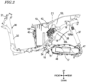
- FIG. 3 is a perspective view of the vehicle body frame 30 and the container box 10 as viewed diagonally from the left front.
- FIG. 4 is a perspective view of the vehicle body frame 30 and the container box 10 as viewed diagonally from the right front.
- FIGS. 3 and 4 both illustrate the vehicle body frame 30 and the container box 10 as viewed diagonally from above.
- the main frame 32 is shaped to extend from the head pipe 31 rearward and diagonally downward, then extend leftward and rightward, and then extend rearward.
- the vehicle body frame 30 further has rear frames 33L and 33R.
- the rear (left) frame 33L is shaped to extend from a left rear portion of the main frame 32 rearward and diagonally upward.
- the rear (right) frame 33R is shaped to extend from a right rear portion of the main frame 32 rearward and diagonally upward.
- a crossing member 34 which extends in a leftward/rightward direction, is provided at a rear portion of the main frame 32 and a front portion of the rear frames 33L and 33R.
- the crossing member 34 supports a swingarm 17 through a pivot 18 in a manner that allows the swingarm 17 to pivot.
- An electric motor 47 is provided at a rear portion of the swingarm 17.
- the electric motor 47 is an in-wheel motor.
- the rear wheel 4 ( FIG. 1 ) is mounted on the electric motor 47.
- the electric motor 47 may be either a direct-drive in-wheel motor or a gear-reduction in-wheel motor.
- the swingarm 17 rotatably supports the rear wheel 4 through the electric motor 47.
- the rear wheel 4 is a driving wheel
- the front wheel 3 is a trailing wheel.
- a rear portion of the rear frame 33L, 33R supports an upper portion of a shock absorber 37 in a manner that allows the shock absorber 37 to oscillate.
- a lower portion of the shock absorber 37 supports the swingarm 17 in a manner that allows the swingarm 17 to pivot.
- a motor control unit (MCU) 46 that controls an operation of the electric motor 47 is provided in the swingarm 17.
- a floorboard 6 for the rider's feet is provided between the front wheel 3 and the rear wheel 4 in a forward/rearward direction of the vehicle 1.
- the floorboard 6 is supported by the main frame 32.
- a seat 5 on which the rider sits is provided at an upper portion of the vehicle body 2.
- the seat 5 is located behind and diagonally above the floorboard 6.
- the container box 10 ( FIG. 2 ) is provided below the seat 5.
- the container box 10 is located between the rear frames 33L and 33R in a leftward/rightward direction of the vehicle 1.
- the container box 10 is supported by the rear frames 33L and 33R and the crossing member 34.
- the container box 10 is open upward.
- the seat 5, which is located on an upper portion of the container box 10, serves as a lid for the container box 10.
- the seat 5, which serves as a lid for the container box 10, is openable and closeable through, for example, a hinge.
- the space inside the container box 10 can accommodate the rider's baggage, a battery, and the like.
- a connector 56 FIG. 3 for connecting the battery is provided in the container box 10.
- FIG. 5 is a diagram illustrating an example of the container box 10 with batteries contained therein.
- two batteries 51 and 52 are provided in the container box 10.
- a plurality of connectors 56 FIG. 3 for connecting the batteries are provided.
- a remaining space behind the batteries 51 and 52 can accommodate the rider's baggage and the like.
- the container box 10 may accommodate one or three or more batteries.
- the connectors 56 for connecting the batteries 51 and 52 may be located at a position higher than a bottom portion of the container box 10. This can substantially prevent the electrode portions of the batteries 51 and 52 and the connectors 56 from getting wet even when water enters the container box 10.
- the batteries 51 and 52 may be removably attached to the vehicle 1 without the need of a tool.
- the batteries 51 and 52 which are removable, can be charged by being connected to an external charger with the batteries 51 and 52 removed from the vehicle 1. For example, even when no charging equipment is provided in a parking garage, the batteries 51 and 52 can be charged in other places such as home.
- the vehicle body cover 20 ( FIG. 1 ) is shaped to cover the vehicle body frame 30 and the container box 10.
- the vehicle body cover 20 has a front cowling 21 and a leg cowling 22, which cover a portion of a front portion of the vehicle 1.
- a headlamp 7 is provided at a front portion of the front cowling 21.
- the vehicle body cover 20 further has a seat cowling 23 and a rear cowling 24, which cover a portion of a rear portion of the vehicle 1.
- the seat cowling 23 and the rear cowling 24 covers the container box 10 and the rear frames 33L and 33R.
- FIG. 6 is a block diagram illustrating an example of a plurality of electrical components provided in the scooter type two-wheeled electric vehicle 1.
- a plurality of electrical components having different functions are provided in the scooter type two-wheeled electric vehicle 1.
- a vehicle control unit (VCU) 41 controls operations of the entire scooter type electric vehicle 1.
- the batteries 51 and 52 output electric power for driving the electric motor 47.
- the output voltages of the batteries 51 and 52 are each, for example, but not limited to, 50 V.
- a battery switcher 42 switches a battery that is used between the batteries 51 and 52.
- the battery switcher 42 is, for example, a relay.
- the VCU 41 controls an operation of the battery switcher 42 to choose a battery that is used from the batteries 51 and 52. For example, when the state of charge of a battery that is currently used is low, the other battery can replace that battery.
- a low-voltage battery 48 supplies electric power to an electrical component that operates with a low voltage.
- the "low voltage” means a voltage that is lower than the output voltages of the batteries 51 and 52.
- the low voltage is, for example, but not limited to, 12 V.
- the low-voltage battery 48 is located, for example, below the floorboard 6 ( FIG. 1 ), or alternatively, may be located at other positions.
- the DC/DC converter 43 reduces a voltage received from the battery 51 or 52 through the battery switcher 42, and outputs the reduced voltage.
- the output voltage of the DC/DC converter 43 is, for example, but not limited to, 12 V.
- the electric power output by the DC/DC converter 43 is supplied to the low-voltage battery 48, which is in turn charged.
- the electric power output by the DC/DC converter 43 may be directly supplied to an electrical component that operates with a low voltage.
- the motor control unit (MCU) 46 generates a drive current from a current received from the battery 51 or 52 through the battery switcher 42, and outputs the drive current to the electric motor 47. Rotation produced by the electric motor 47 is transmitted to the rear wheel 4, which in turn allows the vehicle 1 to travel.
- the positioning device 44 is capable of detecting a location (geographic coordinates) of the vehicle 1 in a geographic coordinate system.
- the positioning device 44 receives a GNSS signal transmitted from a GNSS satellite, and performs positioning based on the GNSS signal.
- GNSS collectively refers to satellite-based positioning systems, such as the global positioning system (GPS), the quasi-zenith satellite system (QZSS, for example, Michibiki), GLONASS, Galileo, and BeiDou.
- Positioning may be performed by any technique that can obtain positional information having a required precision.
- the positioning technique may, for example, be interference positioning or relative positioning.
- the detection of the geographic coordinates of the vehicle 1 allows displaying of a map indicating the current location of the vehicle 1, or navigation to a destination.
- a communication device 45 is used for communication between the vehicle 1 and an external device through a communication network.
- the communication device 45 may allow wireless communication that uses mobile telephony or satellite communications.
- the communication device 45 may be connected to the mobile router by wired or wireless communication. In that case, the communication device 45 is connected to the communication network through the mobile router.
- the communication device 45 may communicate with other vehicles, i.e., may perform inter-vehicle communication.
- the VCU 41 may be connected to a plurality of electrical components through a bus to control operations of the plurality of electrical components.
- the VCU 41 may be connected to each electrical component without through a bus.
- the vehicle 1 may not include the positioning device 44. In the case in which the vehicle 1 does not communicate with any external device, the vehicle 1 may not include the communication device 45. In the case in which the vehicle 1 includes only one battery for supplying power to the electric motor 47, the vehicle 1 may not include the battery switcher 42.
- FIG. 7 is a diagram illustrating the container box 10, the seat cowling 23, and the rear cowling 24 as viewed from above.
- the container box 10 has a first front wall 10F, a first left side wall 10L, a first right side wall 10R, and a first rear wall 10Re.
- the first front wall 10F is located at a front portion of the container box 10, mainly extending in an upward/downward direction and a leftward/rightward direction.
- the first left side wall 10L is located at a left portion of the container box 10, mainly extending in a forward/rearward direction and an upward/downward direction.
- the first right side wall 10R is located at a right portion of the container box 10, mainly extending in a forward/rearward direction and an upward/downward direction.
- the first rear wall 10Re is located at a rear portion of the container box 10, mainly extending in an upward/downward direction and a leftward/rightward direction.
- the first front wall 10F and the first rear wall 10Re are indicated by a solid line
- the first left side wall 10L and the first right side wall 10R are indicated by a dotted line.
- the first front wall 10F, the first rear wall 10Re, the first left side wall 10L, and the first right side wall 10R may be formed integrally or separately.
- the rear cowling 24 has a second left side wall 24L, a second right side wall 24R, and a second rear wall 24Re.
- the second left side wall 24L is located to the left of the first left side wall 10L of the container box 10 and the rear frame 33L ( FIG. 3 ), covering the first left side wall 10L and the rear frame 33L.
- the second right side wall 24R is located to the right of the first right side wall 10R of the container box 10 and the rear frame 33R ( FIG. 4 ), covering the first right side wall 10R and the rear frame 33R.
- the second rear wall 24Re is located behind the first rear wall 10Re of the container box 10, covering the first rear wall 10Re.
- the second left side wall 24L, the second right side wall 24R, and the second rear wall 24Re may be formed integrally or separately.
- the seat cowling 23 is located in front of the first front wall 10F of the container box 10, covering the first front wall 10F.
- the seat cowling 23 is a second front wall covering the first front wall 10F.
- the second front wall 23 and the second rear wall 24Re are indicated by a solid line
- the second left side wall 24L and the second right side wall 24R are indicated by a dashed line.
- the rear frame 33L passes through a position between the first left side wall 10L and the second left side wall 24L.
- the rear frame 33R passes through a position between the first right side wall 10R and the second right side wall 24R.
- an electrical component is provided at each of a position between the first front wall 10F and the second front wall 23, a position between the first left side wall 10L and the second left side wall 24L, and a position between the first right side wall 10R and the second right side wall 24R.
- the battery switcher 42 which is one of the plurality of electrical components, is located between the first front wall 10F and the second front wall 23.
- the DC/DC converter 43 is located between the first left side wall 10L and the second left side wall 24L.
- the VCU 41 is located between the first right side wall 10R and the second right side wall 24R.
- the battery switcher 42 is attached to the first front wall 10F using, for example, a fastening device such as a bolt. By attaching the battery switcher 42 to the first front wall 10F, the battery switcher 42 can be easily located between the first front wall 10F and the second front wall 23.
- the DC/DC converter 43 is attached to the rear frame 33L through, for example, a stay 38.
- the VCU 41 is attached to the rear frame 33R through, for example, a stay 39.
- the DC/DC converter 43 can be easily located between the first left side wall 10L and the second left side wall 24L.
- the VCU 41 can be easily located between the first right side wall 10R and the second right side wall 24R.
- a plurality of electrical components are arranged at distributed positions, i.e., a position between the first front wall 10F and the second front wall 23, a position between the first left side wall 10L and the second left side wall 24L, and a position between the first right side wall 10R and the second right side wall 24R. Therefore, it is not necessary to allocate, in the vehicle 1, a large single space for arranging a plurality of electrical components all in one place.
- a slim volume can accommodate all of the electrical components.
- a plurality of electrical components are distributed, but are arranged around the container box 10, so that a distance between each electrical component is relatively short. Therefore, the length of an electrical cable connecting between each electrical component can be reduced.
- the batteries 51 and 52 are located in the container box 10.
- an electrical cable connected to such an electrical component has a large cross-sectional area.
- the lengths of electrical cables having a large cross-sectional area can be reduced, resulting in a reduction in a space for arranging the electrical cables.
- the reduction in the length of an electrical cable having a large cross-sectional area can lead to a reduction in weight and cost.
- the electrical components are located around the container box 10, i.e., at a relatively high position, the electrical components are less likely to get wet even if water on the road surface enters the vehicle 1.
- An electrical component provided in front of the container box 10 may have a thickness greater than that of an electrical component provided laterally to the container box 10.
- the thickness of an electrical component may refer to a length of the electrical component in a direction in which the outer shape of the electrical component is shortest. It is relatively easy to increase a distance between the first front wall 10F and the second front wall 23. Therefore, by locating an electrical component having a greatest thickness in front of the container box 10, a width in a leftward/rightward direction of the rear cowling 24 can be reduced.
- the DC/DC converter 43 may be attached to the frame 33L at or behind a center portion C1 of the container box 10 in a forward/rearward direction of the vehicle 1.
- the center portion C1 of the container box 10 may be a center position of an inside dimension of the container box 10.
- the VCU 41 may be attached to the frame 33R at or behind the center portion C1 of the container box 10. This allows a front left diagonal portion and a front right diagonal portion of the rear cowling 24 covering the container box 10 to be slim, and therefore, a portion for the rider's feet of the scooter type two-wheeled electric vehicle 1 can have a simple design.
- the rear frames 33L and 33R are shaped to extend rearward and diagonally upward at a position lateral to the container box 10.
- the DC/DC converter 43 and the VCU 41 can be located at a higher position of the vehicle 1 by locating the DC/DC converter 43 and the VCU 41 on the frames 33L and 33R at or behind the center portion C1. Therefore, the DC/DC converter 43 and the VCU 41 are less likely to get wet even if water on the road surface enters the vehicle 1.
- the DC/DC converter 43 may be located inward of the rear frame 33L in a width direction (leftward/rightward direction) of the vehicle 1.
- the VCU 41 may be provided inward of the rear frame 33R in a width direction of the vehicle 1.
- Other electrical components may be provided at a position between the first front wall 10F and the second front wall 23, a position between the first left side wall 10L and the second left side wall 24L, and a position between the first right side wall 10R and the second right side wall 24R.
- the positioning device 44, the communication device 45, the MCU 46, and the like may be provided at such positions.
- a total of four or more electrical components may be provided at the three positions.
- the seat cowling 23 and the rear cowling 24 are provided as a cover for covering the container box 10.
- the seat cowling 23 and the rear cowling 24 may be integrally formed.
- the batteries 51 and 52 may not be removable, and may be fixed to the vehicle 1 so that the batteries 51 and 52 cannot be removed. That the batteries 51 and 52 cannot be removed means that, for example, the batteries 51 and 52 are fixed to the vehicle 1 using a bolt and a nut or the like, and therefore, a certain tool is required in order to remove the batteries 51 and 52.
- the electric motor 47 is not limited to an in-wheel motor.
- the electric motor 47 may be located away from the rear wheel 4, and rotation may be transmitted from the electric motor 47 to the rear wheel 4 through a power transmission mechanism.
- a scooter type electric vehicle 1 includes: a front wheel 3 and a rear wheel 4; an electric motor 47 that produces rotation according to power supplied from a battery 51, 52, and drives at least one of the front wheel 3 and the rear wheel 4; a floorboard 6 that is located between the front wheel 3 and the rear wheel 4, and on which a rider's feet are placed; a seat 5 that is located behind and diagonally above the floorboard 6, and on which the rider sits; a container box 10 that is located below the seat 5, and has a first front wall 10F, a first left side wall 10L, and a first right side wall 10R; a cover 20 that has a second front wall 23 covering the first front wall 10F, a second left side wall 24L covering the first left side wall 10L, and a second right side wall 24R covering the first right side wall 10R; and a first electrical component 42 that is located between the first front wall 10F and the second front wall 23, a second electrical component 43 that is located between the first left side wall 10L and the second left
- a plurality of electrical components are arranged at distributed positions that are a position between the first front wall 10F of the container box 10 and the second front wall 23 of the cover 20, a position between the first left side wall 10L of the container box 10 and the second left side wall 24L of the cover 20, and a position between the first right side wall 10R of the container box 10 and the second right side wall 24R of the cover 20. Therefore, it is not necessary to allocate, in the vehicle 1, a large space for arranging a plurality of electrical components all in one place. By utilizing spaces between the container box 10 and the cover 20, a slim volume can accommodate all of the electrical components.
- a plurality of electrical components are distributed, but are arranged around the container box 10, so that a distance between each electrical component is relatively short. Therefore, the length of an electrical cable connecting between each electrical component can be reduced. For example, as a large current flows through an electrical component that is provided on an electrical path between the battery 51, 52 and the electric motor 47, an electrical cable connected to such an electrical component has a large cross-sectional area.
- the lengths of electrical cables having a large cross-sectional area can be reduced, resulting in a reduction in a space for arranging the electrical cables.
- the reduction in the length of an electrical cable having a large cross-sectional area can lead to a reduction in weight and cost.
- the electrical components are located around the container box 10, i.e., at a relatively high position, the electrical components are less likely to get wet even if water on the road surface enters the vehicle 1.
- the batteries 51 and 52 may be located in the container box 10.
- the electrical cable As a large current flows through an electrical cable that connects the battery 51, 52 and an electrical component, the electrical cable has a large cross-sectional area.
- the lengths of electrical cables having a large cross-sectional area that connect the battery 51, 52 and the electrical components can be reduced.
- the batteries 51 and 52 may be removably attached to the scooter type electric vehicle 1.
- the batteries 51 and 52 can be charged by being connected to an external charger with the batteries 51 and 52 removed from the vehicle 1. For example, even when no charging equipment is provided in a parking garage, the batteries 51 and 52 can be charged.
- the first electrical component 42, the second electrical component 43, and the third electrical component 41 may have different functions.
- the first electrical component 42, the second electrical component 43, and the third electrical component 41 may each be any of a control device 41 that controls an operation of the scooter type electric vehicle 1, a converter 43 that changes the magnitude of the output voltage of the battery 51, 52 and outputs the resultant voltage, a battery switcher 42 that switches a battery which is used between the batteries 51 and 52, a positioning device 44 that detects a location of the scooter type electric vehicle 1 in a geographic coordinate system, and a communication device 45 that performs data communication between the scooter type electric vehicle 1 and an external device.
- a control device 41 that controls an operation of the scooter type electric vehicle 1
- a converter 43 that changes the magnitude of the output voltage of the battery 51, 52 and outputs the resultant voltage
- a battery switcher 42 that switches a battery which is used between the batteries 51 and 52
- a positioning device 44 that detects a location of the scooter type electric vehicle 1 in a geographic coordinate system
- a communication device 45 that performs data communication between the scooter type electric vehicle 1 and an external device.
- the first electrical component 42 located between the first front wall 10F and the second front wall 23 may be thicker than the second electrical component 43 and the third electrical component 41.
- the scooter type electric vehicle 1 may further include a frame 33L that extends through a position between the first left side wall 10L and the second left side wall 24L, and a frame 33R that extends through a position between the first right side wall 10R and the second right side wall 24R. At least one of the second electrical component 43 and the third electrical component 41 may be located inward of the frame 33L, 33R in a width direction of the scooter type electric vehicle 1.
- the scooter type electric vehicle 1 may further include a frame 33L that extends through a position between the first left side wall 10L and the second left side wall 24L, and a frame 33R that extends through a position between the first right side wall 10R and the second right side wall 24R. At least one of the second electrical component 43 and the third electrical component 41 may be located on the frame 33L, 33R.
- the second electrical component 43 and the third electrical component 41 can be easily located between the container box 10 and the cover 20.
- At least one of the second electrical component 43 and the third electrical component 41 may be located at or behind a center portion C1 of the container box 10 in a forward/rearward direction of the scooter type electric vehicle 1.
- a front left diagonal portion and a front right diagonal portion of the cover 20 covering the container box 10 can be slimmed, and therefore, a portion for the rider's feet of the scooter type electric vehicle 1 can have a simple design.
- the scooter type electric vehicle 1 may further include a frame 33L that extends through a position between the first left side wall 10L and the second left side wall 24L, and a frame 33R that extends through a position between the first right side wall 10R and the second right side wall 24R.
- the frame 33L, 33R is shaped to extend rearward and diagonally upward at a position lateral to the container box 10.
- At least one of the second electrical component 43 and the third electrical component 41 may be located on the frame 33L, 33R at or behind the center portion C1 of the container box 10 in a forward/rearward direction of the scooter type electric vehicle 1.
- a front left diagonal portion and a front right diagonal portion of the cover 20 covering the container box 10 can be slimmed, and therefore, a portion for the rider's feet of the scooter type electric vehicle 1 can have a simple design.
- the second electrical component 43 and the third electrical component 41 can be located at a higher position. Therefore, the second electrical component 43 and the third electrical component 41 are less likely to get wet even if water on the road surface enters the vehicle 1.
- the scooter type electric vehicle 1 may further include a swingarm 17 that supports the rear wheel 4.
- the electric motor 47 may be provided on the swingarm 17.
- the scooter type electric vehicle 1 may be a scooter type two-wheeled electric vehicle.
- a number of parts need to be arranged within a limited space in the vehicle 1, and therefore, a limitation is imposed on arrangement of the parts.
- a plurality of electrical components are arranged at distributed positions that are a position between the first front wall 10F of the container box 10 and the second front wall 23 of the cover 20, a position between the first left side wall 10L of the container box 10 and the second left side wall 24L of the cover 20, and a position between the first right side wall 10R of the container box 10 and the second right side wall 24R of the cover 20.
- the present teaching is particularly useful in the field of scooter type electric vehicles including an electric motor as a source of drive power.
Landscapes
- Engineering & Computer Science (AREA)
- Mechanical Engineering (AREA)
- Chemical & Material Sciences (AREA)
- Combustion & Propulsion (AREA)
- Transportation (AREA)
- Automatic Cycles, And Cycles In General (AREA)
Abstract
Description
- The present invention relates to scooter type electric vehicles that are powered by an electric motor to travel.
- There are some scooter type two-wheeled electric vehicles that have an electric motor as a source of power for traveling (see, for example,
JP 2000-253591 A - The electric motor operates with electric power supplied from a battery mounted on the vehicle to rotate. The rotation of the electric motor is transmitted to a wheel, thereby allowing the vehicle to travel.
- A scooter type two-wheeled electric vehicle is equipped with various parts including electrical components. However, in a scooter type two-wheeled electric vehicle, a number of parts need to be arranged within a limited space in the body of the vehicle, and therefore, it is not easy to allocate a space for arrangement of electrical components.
- There has been a demand for further improvement to arrangement of electrical components in a scooter type electric vehicle. It Is the object of the present invention to provide a scooter type electric vehicle having a compact structure. According to the present invention said object is solved by a scooter type electric vehicle having the features of
independent claim 1. Preferred embodiments are laid down in the dependent claims. - A scooter type electric vehicle according to an embodiment includes: a front wheel and a rear wheel; an electric motor that produces rotation according to power supplied from a battery, and drives at least one of the front wheel and the rear wheel; a floorboard that is located between the front wheel and the rear wheel, and on which a rider's feet are placed; a seat that is located behind and diagonally above the floorboard, and on which the rider sits; a container box that is located below the seat, and has a first front wall, a first left side wall, and a first right side wall; a cover that has a second front wall covering the first front wall, a second left side wall covering the first left side wall, and a second right side wall covering the first right side wall; and a first electrical component that is located between the first front wall and the second front wall, a second electrical component that is located between the first left side wall and the second left side wall, and a third electrical component that is located between the first right side wall and the second right side wall.
- If an attempt is made to arrange a plurality of electrical components that are mounted on a scooter type electric vehicle all in one place, it is necessary to allocate, in the vehicle, a large space for arranging the plurality of electrical components together. According to an embodiment, a plurality of electrical components are arranged at distributed positions that are a position between the first front wall of the container box and the second front wall of the cover, a position between the first left side wall of the container box and the second left side wall of the cover, and a position between the first right side wall of the container box and the second right side wall of the cover. Therefore, it is not necessary to allocate, in the vehicle, a large space for arranging a plurality of electrical components all in one place. By utilizing spaces between the container box and the cover, a slim volume can accommodate all of the electrical components.
- A plurality of electrical components are distributed, but are arranged around the container box, so that a distance between each electrical component is relatively short. Therefore, the length of an electrical cable connecting between each electrical component can be reduced. For example, as a large current flows through an electrical component that is provided on an electrical path between the battery and the electric motor, an electrical cable connected to such electrical components has a large cross-sectional area. By providing a plurality of electrical components around the container box, the lengths of electrical cables having a large cross-sectional area can be reduced, resulting in a reduction in a space for arranging the electrical cables. The reduction in the length of an electrical cable having a large cross-sectional area can lead to a reduction in weight and cost.
- As electrical components are located around the container box, i.e., at a relatively high position, the electrical components are less likely to get wet even if water on the road surface enters the vehicle.
- In an embodiment, the battery may be located in the container box.
- As a large current flows through an electrical cable that connects the battery and an electrical component, the electrical cable has a large cross-sectional area. By providing a plurality of electrical components around the container box, the lengths of electrical cables having a large cross-sectional area that connect the battery and the electrical components can be reduced.
- In an embodiment, the battery may be removably attached to the scooter type electric vehicle.
- The battery can be charged by being connected to an external charger with the battery removed from the vehicle. For example, even when no charging equipment is provided in a parking garage, the battery can be charged.
- In an embodiment, the first electrical component, the second electrical component, and the third electrical component may have different functions.
- As it is not necessary to allocate, in the vehicle, a large space for arranging a plurality of electrical components having different functions all in one place, a slim volume can accommodate all of the electrical components.
- In an embodiment, the first electrical component, the second electrical component, and the third electrical component may each be any of a control device that controls an operation of the scooter type electric vehicle, a converter that changes the magnitude of the output voltage of the battery and outputs the resultant voltage, a battery switcher that switches batteries for use, a positioning device that detects a location of the scooter type electric vehicle in a geographic coordinate system, and a communication device that performs data communication between the scooter type electric vehicle and an external device.
- It is not necessary to allocate, in the vehicle, a large space for arranging a plurality of electrical components all in one place, and a slim volume can accommodate all of the electrical components.
- In an embodiment, the first electrical component located between the first front wall and the second front wall may be thicker than the second electrical component and the third electrical component.
- It is relatively easy to increase a distance between the first front wall and the second front wall. Therefore, by locating an electrical component having a greatest thickness in front of the container box, a width in a leftward/rightward direction of the cover covering the container box can be reduced.
- In an embodiment, the scooter type electric vehicle may further include a frame that extends through a position between the first left side wall and the second left side wall and a position between the first right side wall and the second right side wall. At least one of the second electrical component and the third electrical component may be located inward of the frame in a width direction of the scooter type electric vehicle.
- Even if an external force is applied to a side portion of the scooter type electric vehicle, the external force can be substantially prevented from being applied to an electrical component.
- In an embodiment, the scooter type electric vehicle may further include a frame that extends through a position between the first left side wall and the second left side wall and a position between the first right side wall and the second right side wall. At least one of the second electrical component and the third electrical component may be located on the frame.
- The second electrical component and the third electrical component can be easily located between the container box and the cover.
- In an embodiment, at least one of the second electrical component and the third electrical component may be located at or behind a center portion of the container box in a forward/rearward direction of the scooter type electric vehicle.
- A front left diagonal portion and a front right diagonal portion of the cover covering the container box can be slimmed, and therefore, a portion for the rider's feet of the scooter type electric vehicle can have a simple design.
- In an embodiment, the scooter type electric vehicle may further include a frame that extends through a position between the first left side wall and the second left side wall and a position between the first right side wall and the second right side wall. The frame is shaped to extend rearward and diagonally upward at a position lateral to the container box. At least one of the second electrical component and the third electrical component may be located on the frame at or behind the center portion of the container box in a forward/rearward direction of the scooter type electric vehicle.
- A front left diagonal portion and a front right diagonal portion of the cover covering the container box can be slimmed, and therefore, a portion for the rider's feet of the scooter type electric vehicle can have a simple design.
- The second electrical component and the third electrical component can be located at a higher position. Therefore, the second electrical component and the third electrical component are less likely to get wet even if water on the road surface enters the vehicle.
- In an embodiment, the scooter type electric vehicle may further include a swingarm that supports the rear wheel. The electric motor may be provided on the swingarm.
- As it is not necessary to allocate a space for arranging the electric motor in the inside of the vehicle body of the scooter type electric vehicle, the flexibility of arrangement of parts other than the electric motor can be increased.
- In an embodiment, the scooter type electric vehicle may be a scooter type two-wheeled electric vehicle.
- In a scooter type two-wheeled electric vehicle, a number of parts need to be arranged within a limited space in the vehicle, and therefore, a limitation is imposed on arrangement of the parts. According to an embodiment, a plurality of electrical components are arranged at distributed positions that are a position between the first front wall of the container box and the second front wall of the cover, a position between the first left side wall of the container box and the second left side wall of the cover, and a position between the first right side wall of the container box and the second right side wall of the cover. By utilizing spaces between the container box and the cover, a slim volume can accommodate all of the electrical components.
- According to an embodiment, a plurality of electrical components are arranged at distributed positions that are a position between the first front wall of the container box and the second front wall of the cover, a position between the first left side wall of the container box and the second left side wall of the cover, and a position between the first right side wall of the container box and the second right side wall of the cover. Therefore, it is not necessary to allocate, in the vehicle, a large space for arranging a plurality of electrical components all in one place. By utilizing spaces between the container box and the cover, a slim volume can accommodate all of the electrical components.
- A plurality of electrical components are distributed, but are arranged around the container box, so that a distance between each electrical component is relatively short. Therefore, the length of an electrical cable connecting between each electrical component can be reduced. For example, as a large current flows through an electrical component that is provided on an electrical path between the battery and the electric motor, an electrical cable connected to such electrical components has a large cross-sectional area. By providing a plurality of electrical components around the container box, the lengths of electrical cables having a large cross-sectional area can be reduced, resulting in a reduction in a space for arranging the electrical cables. The reduction in the length of an electrical cable having a large cross-sectional area can lead to a reduction in weight and cost.
- As electrical components are located around the container box, i.e., at a relatively high position, the electrical components are less likely to get wet even if water on the road surface enters the vehicle.
-
-
FIG. 1 is a left side view illustrating a scooter typeelectric vehicle 1 according to an embodiment. -
FIG. 2 is a left side view illustrating avehicle body frame 30 and acontainer box 10 according to an embodiment. -
FIG. 3 is a perspective view of avehicle body frame 30 and acontainer box 10 according to an embodiment as viewed diagonally from the left front. -
FIG. 4 is a perspective view of avehicle body frame 30 and acontainer box 10 according to an embodiment as viewed diagonally from the right front. -
FIG. 5 is a diagram illustrating acontainer box 10 withbatteries -
FIG. 6 is a block diagram illustrating an example of a plurality of electrical components provided in a scooter typeelectric vehicle 1 according to an embodiment. -
FIG. 7 is a diagram illustrating acontainer box 10, aseat cowling 23, and arear cowling 24 according to an embodiment. - Preferred embodiments will be described below with reference to the accompanying drawings. In the description of the embodiments, like parts are indicated by like reference characters and will not be redundantly described. The front and rear, top and bottom, and left and right of a scooter type electric vehicle each have a meaning that is defined in relation to a rider who is sitting on the seat of the vehicle.
-
FIG. 1 is a left side view illustrating a scooter typeelectric vehicle 1 according to an embodiment. In the example illustrated inFIG. 1 , thevehicle 1 is a scooter type two-wheeled electric vehicle. Thevehicle 1 may be a scooter type electric vehicle with three or more wheels. An example in which thevehicle 1 is a scooter type two-wheeled electric vehicle will be described below.FIG. 2 is a left side view illustrating avehicle body frame 30 and acontainer box 10 included in the scooter type two-wheeledelectric vehicle 1. - The scooter type two-wheeled
electric vehicle 1 includes avehicle body 2, afront wheel 3, and arear wheel 4. Thevehicle body 2 has a structure including a vehicle body frame 30 (FIG. 2 ) and a vehicle body cover 20 (FIG. 1 ) covering at least a portion of thevehicle body frame 30. Thevehicle body frame 30 is, for example, an underbone frame. Thevehicle body frame 30 has ahead pipe 31 and amain frame 32. A steering shaft is inserted in thehead pipe 31. A steeringhandlebar 16 is provided at an upper end of the steering shaft. Afront fork 15 is provided at a lower end of the steering shaft. Thefront wheel 3 is rotatably supported at a lower end of thefront fork 15. -
FIG. 3 is a perspective view of thevehicle body frame 30 and thecontainer box 10 as viewed diagonally from the left front.FIG. 4 is a perspective view of thevehicle body frame 30 and thecontainer box 10 as viewed diagonally from the right front.FIGS. 3 and4 both illustrate thevehicle body frame 30 and thecontainer box 10 as viewed diagonally from above. - As illustrated in
FIGS. 2 to 4 , themain frame 32 is shaped to extend from thehead pipe 31 rearward and diagonally downward, then extend leftward and rightward, and then extend rearward. Thevehicle body frame 30 further hasrear frames frame 33L is shaped to extend from a left rear portion of themain frame 32 rearward and diagonally upward. The rear (right)frame 33R is shaped to extend from a right rear portion of themain frame 32 rearward and diagonally upward. - A crossing
member 34, which extends in a leftward/rightward direction, is provided at a rear portion of themain frame 32 and a front portion of therear frames member 34 supports aswingarm 17 through apivot 18 in a manner that allows theswingarm 17 to pivot. Anelectric motor 47 is provided at a rear portion of theswingarm 17. Theelectric motor 47 is an in-wheel motor. The rear wheel 4 (FIG. 1 ) is mounted on theelectric motor 47. Theelectric motor 47 may be either a direct-drive in-wheel motor or a gear-reduction in-wheel motor. Theswingarm 17 rotatably supports therear wheel 4 through theelectric motor 47. In this example, therear wheel 4 is a driving wheel, and thefront wheel 3 is a trailing wheel. A rear portion of therear frame shock absorber 37 in a manner that allows theshock absorber 37 to oscillate. A lower portion of theshock absorber 37 supports theswingarm 17 in a manner that allows theswingarm 17 to pivot. A motor control unit (MCU) 46 that controls an operation of theelectric motor 47 is provided in theswingarm 17. - By providing the
electric motor 47 and theMCU 46 on and in theswingarm 17, it is not necessary to allocate a space for arranging theelectric motor 47 and theMCU 46 in the inside of thevehicle body 2. Therefore, the flexibility of arrangement of parts other than theelectric motor 47 and theMCU 46 can be increased. - As illustrated in
FIG. 1 , afloorboard 6 for the rider's feet is provided between thefront wheel 3 and therear wheel 4 in a forward/rearward direction of thevehicle 1. Thefloorboard 6 is supported by themain frame 32. Aseat 5 on which the rider sits is provided at an upper portion of thevehicle body 2. Theseat 5 is located behind and diagonally above thefloorboard 6. The container box 10 (FIG. 2 ) is provided below theseat 5. - The
container box 10 is located between therear frames vehicle 1. Thecontainer box 10 is supported by therear frames member 34. - The
container box 10 is open upward. Theseat 5, which is located on an upper portion of thecontainer box 10, serves as a lid for thecontainer box 10. Theseat 5, which serves as a lid for thecontainer box 10, is openable and closeable through, for example, a hinge. The space inside thecontainer box 10 can accommodate the rider's baggage, a battery, and the like. In the case in which a battery is contained in thecontainer box 10, a connector 56 (FIG. 3 ) for connecting the battery is provided in thecontainer box 10. -
FIG. 5 is a diagram illustrating an example of thecontainer box 10 with batteries contained therein. In the example ofFIG. 5 , twobatteries container box 10. In the case in which a plurality of batteries are contained in thecontainer box 10, a plurality of connectors 56 (FIG. 3 ) for connecting the batteries are provided. In the example ofFIG. 5 , a remaining space behind thebatteries container box 10 may accommodate one or three or more batteries. - The
connectors 56 for connecting thebatteries container box 10. This can substantially prevent the electrode portions of thebatteries connectors 56 from getting wet even when water enters thecontainer box 10. - The
batteries vehicle 1 without the need of a tool. Thebatteries batteries vehicle 1. For example, even when no charging equipment is provided in a parking garage, thebatteries - The vehicle body cover 20 (
FIG. 1 ) is shaped to cover thevehicle body frame 30 and thecontainer box 10. Thevehicle body cover 20 has afront cowling 21 and aleg cowling 22, which cover a portion of a front portion of thevehicle 1. Aheadlamp 7 is provided at a front portion of thefront cowling 21. - The vehicle body cover 20 further has a
seat cowling 23 and arear cowling 24, which cover a portion of a rear portion of thevehicle 1. Theseat cowling 23 and therear cowling 24 covers thecontainer box 10 and therear frames - Next, a plurality of electrical components that are provided in the scooter type two-wheeled
electric vehicle 1 will be described.FIG. 6 is a block diagram illustrating an example of a plurality of electrical components provided in the scooter type two-wheeledelectric vehicle 1. A plurality of electrical components having different functions are provided in the scooter type two-wheeledelectric vehicle 1. - A vehicle control unit (VCU) 41 controls operations of the entire scooter type
electric vehicle 1. Thebatteries electric motor 47. The output voltages of thebatteries A battery switcher 42 switches a battery that is used between thebatteries battery switcher 42 is, for example, a relay. TheVCU 41 controls an operation of thebattery switcher 42 to choose a battery that is used from thebatteries - A low-
voltage battery 48 supplies electric power to an electrical component that operates with a low voltage. The "low voltage" means a voltage that is lower than the output voltages of thebatteries voltage battery 48 is located, for example, below the floorboard 6 (FIG. 1 ), or alternatively, may be located at other positions. - The DC/
DC converter 43 reduces a voltage received from thebattery battery switcher 42, and outputs the reduced voltage. The output voltage of the DC/DC converter 43 is, for example, but not limited to, 12 V. The electric power output by the DC/DC converter 43 is supplied to the low-voltage battery 48, which is in turn charged. The electric power output by the DC/DC converter 43 may be directly supplied to an electrical component that operates with a low voltage. - The motor control unit (MCU) 46 generates a drive current from a current received from the
battery battery switcher 42, and outputs the drive current to theelectric motor 47. Rotation produced by theelectric motor 47 is transmitted to therear wheel 4, which in turn allows thevehicle 1 to travel. - The
positioning device 44 is capable of detecting a location (geographic coordinates) of thevehicle 1 in a geographic coordinate system. Thepositioning device 44 receives a GNSS signal transmitted from a GNSS satellite, and performs positioning based on the GNSS signal. GNSS collectively refers to satellite-based positioning systems, such as the global positioning system (GPS), the quasi-zenith satellite system (QZSS, for example, Michibiki), GLONASS, Galileo, and BeiDou. Positioning may be performed by any technique that can obtain positional information having a required precision. The positioning technique may, for example, be interference positioning or relative positioning. The detection of the geographic coordinates of thevehicle 1 allows displaying of a map indicating the current location of thevehicle 1, or navigation to a destination. - A
communication device 45 is used for communication between thevehicle 1 and an external device through a communication network. Thecommunication device 45 may allow wireless communication that uses mobile telephony or satellite communications. When the rider is carrying a mobile router, thecommunication device 45 may be connected to the mobile router by wired or wireless communication. In that case, thecommunication device 45 is connected to the communication network through the mobile router. Thecommunication device 45 may communicate with other vehicles, i.e., may perform inter-vehicle communication. - The
VCU 41 may be connected to a plurality of electrical components through a bus to control operations of the plurality of electrical components. TheVCU 41 may be connected to each electrical component without through a bus. - It should be noted that in the case in which information about the location of the
vehicle 1 is not used, thevehicle 1 may not include thepositioning device 44. In the case in which thevehicle 1 does not communicate with any external device, thevehicle 1 may not include thecommunication device 45. In the case in which thevehicle 1 includes only one battery for supplying power to theelectric motor 47, thevehicle 1 may not include thebattery switcher 42. - Next, an example of arrangement of a plurality of electrical components will be described.
FIG. 7 is a diagram illustrating thecontainer box 10, theseat cowling 23, and therear cowling 24 as viewed from above. - As illustrated in
FIGS. 3 ,4 , and7 , thecontainer box 10 has a firstfront wall 10F, a firstleft side wall 10L, a firstright side wall 10R, and a first rear wall 10Re. The firstfront wall 10F is located at a front portion of thecontainer box 10, mainly extending in an upward/downward direction and a leftward/rightward direction. The firstleft side wall 10L is located at a left portion of thecontainer box 10, mainly extending in a forward/rearward direction and an upward/downward direction. The firstright side wall 10R is located at a right portion of thecontainer box 10, mainly extending in a forward/rearward direction and an upward/downward direction. The first rear wall 10Re is located at a rear portion of thecontainer box 10, mainly extending in an upward/downward direction and a leftward/rightward direction. InFIG. 7 , the firstfront wall 10F and the first rear wall 10Re are indicated by a solid line, and the firstleft side wall 10L and the firstright side wall 10R are indicated by a dotted line. The firstfront wall 10F, the first rear wall 10Re, the firstleft side wall 10L, and the firstright side wall 10R may be formed integrally or separately. - The
rear cowling 24 has a secondleft side wall 24L, a secondright side wall 24R, and a second rear wall 24Re. The secondleft side wall 24L is located to the left of the firstleft side wall 10L of thecontainer box 10 and therear frame 33L (FIG. 3 ), covering the firstleft side wall 10L and therear frame 33L. The secondright side wall 24R is located to the right of the firstright side wall 10R of thecontainer box 10 and therear frame 33R (FIG. 4 ), covering the firstright side wall 10R and therear frame 33R. The second rear wall 24Re is located behind the first rear wall 10Re of thecontainer box 10, covering the first rear wall 10Re. The secondleft side wall 24L, the secondright side wall 24R, and the second rear wall 24Re may be formed integrally or separately. - The
seat cowling 23 is located in front of the firstfront wall 10F of thecontainer box 10, covering the firstfront wall 10F. Theseat cowling 23 is a second front wall covering the firstfront wall 10F. InFIG. 7 , the secondfront wall 23 and the second rear wall 24Re are indicated by a solid line, and the secondleft side wall 24L and the secondright side wall 24R are indicated by a dashed line. Therear frame 33L passes through a position between the firstleft side wall 10L and the secondleft side wall 24L. Therear frame 33R passes through a position between the firstright side wall 10R and the secondright side wall 24R. - In this embodiment, an electrical component is provided at each of a position between the first
front wall 10F and the secondfront wall 23, a position between the firstleft side wall 10L and the secondleft side wall 24L, and a position between the firstright side wall 10R and the secondright side wall 24R. - As an example, the
battery switcher 42, which is one of the plurality of electrical components, is located between the firstfront wall 10F and the secondfront wall 23. The DC/DC converter 43 is located between the firstleft side wall 10L and the secondleft side wall 24L. TheVCU 41 is located between the firstright side wall 10R and the secondright side wall 24R. - The
battery switcher 42 is attached to the firstfront wall 10F using, for example, a fastening device such as a bolt. By attaching thebattery switcher 42 to the firstfront wall 10F, thebattery switcher 42 can be easily located between the firstfront wall 10F and the secondfront wall 23. - The DC/
DC converter 43 is attached to therear frame 33L through, for example, astay 38. TheVCU 41 is attached to therear frame 33R through, for example, astay 39. By attaching the DC/DC converter 43 to therear frame 33L, the DC/DC converter 43 can be easily located between the firstleft side wall 10L and the secondleft side wall 24L. By attaching theVCU 41 to therear frame 33R, theVCU 41 can be easily located between the firstright side wall 10R and the secondright side wall 24R. - If an attempt is made to arrange a plurality of electrical components that are mounted on the scooter type two-wheeled
electric vehicle 1 all in one place, it is necessary to allocate, in thevehicle 1, a large space for arranging the plurality of electrical components together. In this embodiment, a plurality of electrical components are arranged at distributed positions, i.e., a position between the firstfront wall 10F and the secondfront wall 23, a position between the firstleft side wall 10L and the secondleft side wall 24L, and a position between the firstright side wall 10R and the secondright side wall 24R. Therefore, it is not necessary to allocate, in thevehicle 1, a large single space for arranging a plurality of electrical components all in one place. By utilizing spaces between thecontainer box 10 and thecowlings - A plurality of electrical components are distributed, but are arranged around the
container box 10, so that a distance between each electrical component is relatively short. Therefore, the length of an electrical cable connecting between each electrical component can be reduced. - In this embodiment, the
batteries container box 10. For example, as a large current flows through an electrical component that is provided on an electrical path between thebattery electric motor 47, an electrical cable connected to such an electrical component has a large cross-sectional area. By providing a plurality of electrical components around thecontainer box 10, the lengths of electrical cables having a large cross-sectional area can be reduced, resulting in a reduction in a space for arranging the electrical cables. The reduction in the length of an electrical cable having a large cross-sectional area can lead to a reduction in weight and cost. - In addition, as electrical components are located around the
container box 10, i.e., at a relatively high position, the electrical components are less likely to get wet even if water on the road surface enters thevehicle 1. - An electrical component provided in front of the
container box 10 may have a thickness greater than that of an electrical component provided laterally to thecontainer box 10. Here, the thickness of an electrical component may refer to a length of the electrical component in a direction in which the outer shape of the electrical component is shortest. It is relatively easy to increase a distance between the firstfront wall 10F and the secondfront wall 23. Therefore, by locating an electrical component having a greatest thickness in front of thecontainer box 10, a width in a leftward/rightward direction of therear cowling 24 can be reduced. - As illustrated in
FIG. 2 , the DC/DC converter 43 may be attached to theframe 33L at or behind a center portion C1 of thecontainer box 10 in a forward/rearward direction of thevehicle 1. The center portion C1 of thecontainer box 10 may be a center position of an inside dimension of thecontainer box 10. Likewise, theVCU 41 may be attached to theframe 33R at or behind the center portion C1 of thecontainer box 10. This allows a front left diagonal portion and a front right diagonal portion of therear cowling 24 covering thecontainer box 10 to be slim, and therefore, a portion for the rider's feet of the scooter type two-wheeledelectric vehicle 1 can have a simple design. - The
rear frames container box 10. The DC/DC converter 43 and theVCU 41 can be located at a higher position of thevehicle 1 by locating the DC/DC converter 43 and theVCU 41 on theframes DC converter 43 and theVCU 41 are less likely to get wet even if water on the road surface enters thevehicle 1. - As illustrated in
FIG. 3 , the DC/DC converter 43 may be located inward of therear frame 33L in a width direction (leftward/rightward direction) of thevehicle 1. As illustrated inFIG. 4 , theVCU 41 may be provided inward of therear frame 33R in a width direction of thevehicle 1. By locating an electrical component inward of therear frame vehicle 1, the external force can be substantially prevented from being applied to the electrical component. In addition, a width in a leftward/rightward direction of therear cowling 24 can be reduced. - Other electrical components may be provided at a position between the first
front wall 10F and the secondfront wall 23, a position between the firstleft side wall 10L and the secondleft side wall 24L, and a position between the firstright side wall 10R and the secondright side wall 24R. For example, thepositioning device 44, thecommunication device 45, theMCU 46, and the like may be provided at such positions. A total of four or more electrical components may be provided at the three positions. - In the foregoing embodiments, the
seat cowling 23 and therear cowling 24 are provided as a cover for covering thecontainer box 10. Theseat cowling 23 and therear cowling 24 may be integrally formed. - The
batteries vehicle 1 so that thebatteries batteries batteries vehicle 1 using a bolt and a nut or the like, and therefore, a certain tool is required in order to remove thebatteries - The
electric motor 47 is not limited to an in-wheel motor. Theelectric motor 47 may be located away from therear wheel 4, and rotation may be transmitted from theelectric motor 47 to therear wheel 4 through a power transmission mechanism. - In the foregoing, preferred illustrative embodiments have been described.
- A scooter type electric vehicle 1 according to an embodiment includes: a front wheel 3 and a rear wheel 4; an electric motor 47 that produces rotation according to power supplied from a battery 51, 52, and drives at least one of the front wheel 3 and the rear wheel 4; a floorboard 6 that is located between the front wheel 3 and the rear wheel 4, and on which a rider's feet are placed; a seat 5 that is located behind and diagonally above the floorboard 6, and on which the rider sits; a container box 10 that is located below the seat 5, and has a first front wall 10F, a first left side wall 10L, and a first right side wall 10R; a cover 20 that has a second front wall 23 covering the first front wall 10F, a second left side wall 24L covering the first left side wall 10L, and a second right side wall 24R covering the first right side wall 10R; and a first electrical component 42 that is located between the first front wall 10F and the second front wall 23, a second electrical component 43 that is located between the first left side wall 10L and the second left side wall 24L, and a third electrical component 41 that is located between the first right side wall 10R and the second right side wall 24R.
- If an attempt is made to arrange a plurality of electrical components that are mounted on the scooter type
electric vehicle 1 all in one place, it is necessary to allocate, in thevehicle 1, a large space for arranging the plurality of electrical components together. - According to an embodiment, a plurality of electrical components are arranged at distributed positions that are a position between the first
front wall 10F of thecontainer box 10 and the secondfront wall 23 of thecover 20, a position between the firstleft side wall 10L of thecontainer box 10 and the secondleft side wall 24L of thecover 20, and a position between the firstright side wall 10R of thecontainer box 10 and the secondright side wall 24R of thecover 20. Therefore, it is not necessary to allocate, in thevehicle 1, a large space for arranging a plurality of electrical components all in one place. By utilizing spaces between thecontainer box 10 and thecover 20, a slim volume can accommodate all of the electrical components. - A plurality of electrical components are distributed, but are arranged around the
container box 10, so that a distance between each electrical component is relatively short. Therefore, the length of an electrical cable connecting between each electrical component can be reduced. For example, as a large current flows through an electrical component that is provided on an electrical path between thebattery electric motor 47, an electrical cable connected to such an electrical component has a large cross-sectional area. By providing a plurality of electrical components around thecontainer box 10, the lengths of electrical cables having a large cross-sectional area can be reduced, resulting in a reduction in a space for arranging the electrical cables. The reduction in the length of an electrical cable having a large cross-sectional area can lead to a reduction in weight and cost. - As electrical components are located around the
container box 10, i.e., at a relatively high position, the electrical components are less likely to get wet even if water on the road surface enters thevehicle 1. - In an embodiment, the
batteries container box 10. - As a large current flows through an electrical cable that connects the
battery container box 10, the lengths of electrical cables having a large cross-sectional area that connect thebattery - In an embodiment, the
batteries electric vehicle 1. - The
batteries batteries vehicle 1. For example, even when no charging equipment is provided in a parking garage, thebatteries - In an embodiment, the first
electrical component 42, the secondelectrical component 43, and the thirdelectrical component 41 may have different functions. - As it is not necessary to allocate, in the
vehicle 1, a large space for arranging a plurality of electrical components having different functions all in one place, a slim volume can accommodate all of the electrical components. - In an embodiment, the first
electrical component 42, the secondelectrical component 43, and the thirdelectrical component 41 may each be any of acontrol device 41 that controls an operation of the scooter typeelectric vehicle 1, aconverter 43 that changes the magnitude of the output voltage of thebattery battery switcher 42 that switches a battery which is used between thebatteries positioning device 44 that detects a location of the scooter typeelectric vehicle 1 in a geographic coordinate system, and acommunication device 45 that performs data communication between the scooter typeelectric vehicle 1 and an external device. - It is not necessary to allocate, in the
vehicle 1, a large space for arranging a plurality of electrical components all in one place, and a slim volume can accommodate all of the electrical components. - In an embodiment, the first
electrical component 42 located between the firstfront wall 10F and the secondfront wall 23 may be thicker than the secondelectrical component 43 and the thirdelectrical component 41. - It is relatively easy to increase a distance between the first
front wall 10F and the secondfront wall 23. Therefore, by locating an electrical component having a greatest thickness in front of thecontainer box 10, a width in a leftward/rightward direction of thecover 20 covering thecontainer box 10 can be reduced. - In an embodiment, the scooter type
electric vehicle 1 may further include aframe 33L that extends through a position between the firstleft side wall 10L and the secondleft side wall 24L, and aframe 33R that extends through a position between the firstright side wall 10R and the secondright side wall 24R. At least one of the secondelectrical component 43 and the thirdelectrical component 41 may be located inward of theframe electric vehicle 1. - Even if an external force is applied to a side portion of the scooter type
electric vehicle 1, the external force can be substantially prevented from being applied to an electrical component. - In an embodiment, the scooter type
electric vehicle 1 may further include aframe 33L that extends through a position between the firstleft side wall 10L and the secondleft side wall 24L, and aframe 33R that extends through a position between the firstright side wall 10R and the secondright side wall 24R. At least one of the secondelectrical component 43 and the thirdelectrical component 41 may be located on theframe - The second
electrical component 43 and the thirdelectrical component 41 can be easily located between thecontainer box 10 and thecover 20. - In an embodiment, at least one of the second
electrical component 43 and the thirdelectrical component 41 may be located at or behind a center portion C1 of thecontainer box 10 in a forward/rearward direction of the scooter typeelectric vehicle 1. - A front left diagonal portion and a front right diagonal portion of the
cover 20 covering thecontainer box 10 can be slimmed, and therefore, a portion for the rider's feet of the scooter typeelectric vehicle 1 can have a simple design. - In an embodiment, the scooter type
electric vehicle 1 may further include aframe 33L that extends through a position between the firstleft side wall 10L and the secondleft side wall 24L, and aframe 33R that extends through a position between the firstright side wall 10R and the secondright side wall 24R. Theframe container box 10. At least one of the secondelectrical component 43 and the thirdelectrical component 41 may be located on theframe container box 10 in a forward/rearward direction of the scooter typeelectric vehicle 1. - A front left diagonal portion and a front right diagonal portion of the
cover 20 covering thecontainer box 10 can be slimmed, and therefore, a portion for the rider's feet of the scooter typeelectric vehicle 1 can have a simple design. - The second
electrical component 43 and the thirdelectrical component 41 can be located at a higher position. Therefore, the secondelectrical component 43 and the thirdelectrical component 41 are less likely to get wet even if water on the road surface enters thevehicle 1. - In an embodiment, the scooter type
electric vehicle 1 may further include aswingarm 17 that supports therear wheel 4. Theelectric motor 47 may be provided on theswingarm 17. - As it is not necessary to allocate a space for arranging the
electric motor 47 in the inside of the vehicle body of the scooter typeelectric vehicle 1, the flexibility of arrangement of parts other than theelectric motor 47 can be increased. - In an embodiment, the scooter type
electric vehicle 1 may be a scooter type two-wheeled electric vehicle. - In the scooter type two-wheeled
electric vehicle 1, a number of parts need to be arranged within a limited space in thevehicle 1, and therefore, a limitation is imposed on arrangement of the parts. According to an embodiment, a plurality of electrical components are arranged at distributed positions that are a position between the firstfront wall 10F of thecontainer box 10 and the secondfront wall 23 of thecover 20, a position between the firstleft side wall 10L of thecontainer box 10 and the secondleft side wall 24L of thecover 20, and a position between the firstright side wall 10R of thecontainer box 10 and the secondright side wall 24R of thecover 20. By utilizing spaces between thecontainer box 10 and thecover 20, a slim volume can accommodate all of the electrical components. - The present teaching is particularly useful in the field of scooter type electric vehicles including an electric motor as a source of drive power.
Claims (15)
- A scooter type electric vehicle (1) comprising:a front wheel (3) and a rear wheel (4);an electric motor (47) configured for producing rotation according to power supplied from a battery (51, 52), and configured for driving at least one of the front wheel (3) and the rear wheel (4);a floorboard (6) located between the front wheel (3) and the rear wheel (4) in forward/rearward direction of the vehicle, wherein the floorboard (6) is configured to place a rider's feet;a seat (5) located behind and diagonally above the floorboard (6) in forward/rearward direction and in upward/downward direction of the vehicle, wherein the seat (5) is configured for the rider to sit on;a container box (10) located below the seat (5) in upward/downward direction of the vehicle, and having a first front wall (10F) in forward/rearward direction of the vehicle, and a first left side wall (10L) and a first right side wall (10R) in leftward/rightward direction of the vehicle;a cover (20) having a second front wall (23) covering the first front wall (10F) in forward/rearward direction of the vehicle, and a second left side wall (24L) covering the first left side wall (10L) and a second right side wall (24R) covering the first right side wall (10R) in leftward/rightward direction of the vehicle; anda first electrical component (42) located between the first front wall (10F) and the second front wall (23), a second electrical component (43) located between the first left side wall (10L) and the second left side wall (24L), and a third electrical component (41) located between the first right side wall (10R) and the second right side wall (24R).
- The scooter type electric vehicle (1) according to claim 1, wherein the battery (51, 52) is located in the container box (10).
- The scooter type electric vehicle (1) according to claim 1 or 2, wherein the battery (51, 52) is removably attached to the scooter type electric vehicle (1).
- The scooter type electric vehicle (1) according to any of claims 1 to 3, wherein the first electrical component (42), the second electrical component (43), and the third electrical component (41) have different functions.
- The scooter type electric vehicle (1) according to any of claims 1 to 4, wherein the first electrical component (42), the second electrical component (43), and the third electrical component (41) are each any of a control device (41) for controlling an operation of the scooter type electric vehicle (1), a converter (43) for changing the magnitude of an output voltage of the battery (51, 52), and outputting the changed voltage, a battery switcher (42) for switching batteries for use, a positioning device (44) for detecting a location of the scooter type electric vehicle (1) in a geographic coordinate system, and a communication device (45) for performing data communication between the scooter type electric vehicle (1) and an external device.
- The scooter type electric vehicle (1) according to any of claims 1 to 5, wherein a thickness in forward/rearward direction of the vehicle of the first electrical component (42) located between the first front wall (10F) and the second front wall (23) is greater than a thickness in leftward/rightward direction of the vehicle of each of the second electrical component (43) and the third electrical component (41) in forward/rearward direction of the vehicle.
- The scooter type electric vehicle (1) according to any of claims 1 to 6, further comprising:a left frame (33L) extending through a position between the first left side wall (10L) and the second left side wall (24L) anda right frame (33R) extending through a position between the first right side wall (10R) and the second right side wall (24R).
- The scooter type electric vehicle (1) according to 7, wherein the left frame (33L) and the right frame (33R) are shaped to extend rearward and diagonally upward in forward/rearward direction and in upward/downward direction of the vehicle at a position lateral to the container box (10) in leftward/rightward direction of the vehicle.
- The scooter type electric vehicle (1) according to claim 7 or 8, wherein at least one of the second electrical component (43) and the third electrical component (41) is located inward of the left frame (33L) and the right frame (33R) in a width direction of the vehicle (1).
- The scooter type electric vehicle (1) according to any of claims 7 to 9, wherein at least one of the second electrical component (43) and the third electrical component (41) is located on the left frame (33L) or the right frame (33R).
- The scooter type electric vehicle (1) according to any of claims 1 to 10, wherein at least one of the second electrical component (43) and the third electrical component (41) is located at or behind a center portion (C1) of the container box (10) in forward/rearward direction of the vehicle.
- The scooter type electric vehicle (1) according to any of claims 1 to 11, further comprising:a swingarm (17) for supporting the rear wheel (4), whereinthe electric motor (47) is provided on the swingarm (17).
- The scooter type electric vehicle (1) according to claim 12, wherein a rear portion of the one of the left or right frame (33L, 33R) supports an upper portion of a shock absorber (37) and lower portion of the shock absorber (37) supports the swingarm (17) in a manner that allows the swingarm (17) to pivot.
- The scooter type electric vehicle (1) according to any of claims 1 to 12, wherein a main frame (32) is shaped to extend from a head pipe (31) rearward and diagonally downward in forward/rearward direction and in upward/downward direction of the vehicle, then extend leftward and rightward in leftward/rightward direction of the vehicle, and then extend rearward in forward/rearward direction of the vehicle, a left frame (33L) is shaped to extend from a left rear portion of the main frame (32) rearward and diagonally upward in forward/rearward direction and in upward/downward direction of the vehicle, and a right frame (33R) is shaped to extend from a right rear portion of the main frame (32) rearward and diagonally upward in forward/rearward direction and in upward/downward direction of the vehicle.
- The scooter type electric vehicle (1) according to any of claims 1 to 14, wherein the scooter type electric vehicle (1) is a scooter type two-wheeled electric vehicle.
Applications Claiming Priority (1)
| Application Number | Priority Date | Filing Date | Title |
|---|---|---|---|
| JP2022035400A JP2023130859A (en) | 2022-03-08 | 2022-03-08 | scooter type electric vehicle |
Publications (1)
| Publication Number | Publication Date |
|---|---|
| EP4242092A1 true EP4242092A1 (en) | 2023-09-13 |
Family
ID=85380787
Family Applications (1)
| Application Number | Title | Priority Date | Filing Date |
|---|---|---|---|
| EP23158209.9A Withdrawn EP4242092A1 (en) | 2022-03-08 | 2023-02-23 | Scooter type electric vehicle |
Country Status (4)
| Country | Link |
|---|---|
| US (1) | US20230286610A1 (en) |
| EP (1) | EP4242092A1 (en) |
| JP (1) | JP2023130859A (en) |
| BR (1) | BR102023004189A2 (en) |
Citations (8)
| Publication number | Priority date | Publication date | Assignee | Title |
|---|---|---|---|---|
| JP2000253591A (en) | 1999-03-01 | 2000-09-14 | Tokyo R & D:Kk | Electric car |
| TW201041212A (en) * | 2009-03-27 | 2010-11-16 | Honda Motor Co Ltd | Battery device for electric motorcycle |
| US20120176086A1 (en) * | 2009-08-31 | 2012-07-12 | Honda Motor Co., Ltd. | Battery charger and battery charger attaching structure |
| TW201242806A (en) * | 2011-02-16 | 2012-11-01 | Honda Motor Co Ltd | Electric vehicle |
| JP2014113971A (en) * | 2012-12-12 | 2014-06-26 | Honda Motor Co Ltd | Arrangement structure of on-vehicle electrical component |
| WO2015092818A1 (en) * | 2013-12-18 | 2015-06-25 | Tvs Motor Company Limited | Storage container for a vehicle |
| US20150266535A1 (en) * | 2014-03-20 | 2015-09-24 | Askoll Eva S.R.L. | Electric propulsion unit and torque transmission group for an electric scooter and corresponding scooter |
| CN212709807U (en) * | 2020-07-30 | 2021-03-16 | 光阳工业股份有限公司 | Arrangement structure of keyless controller of vehicle |
Family Cites Families (3)
| Publication number | Priority date | Publication date | Assignee | Title |
|---|---|---|---|---|
| JP3868944B2 (en) * | 2003-09-29 | 2007-01-17 | 本田技研工業株式会社 | Battery arrangement structure in a vehicle |
| JP5421995B2 (en) * | 2009-08-31 | 2014-02-19 | 本田技研工業株式会社 | Charger mounting structure |
| JP2018012346A (en) * | 2015-10-02 | 2018-01-25 | ヤマハ発動機株式会社 | Vehicle, and engine and power generation unit for driving vehicle |
-
2022
- 2022-03-08 JP JP2022035400A patent/JP2023130859A/en active Pending
-
2023
- 2023-02-23 EP EP23158209.9A patent/EP4242092A1/en not_active Withdrawn
- 2023-03-06 BR BR102023004189-2A patent/BR102023004189A2/en active Search and Examination
- 2023-03-07 US US18/118,164 patent/US20230286610A1/en active Pending
Patent Citations (8)
| Publication number | Priority date | Publication date | Assignee | Title |
|---|---|---|---|---|
| JP2000253591A (en) | 1999-03-01 | 2000-09-14 | Tokyo R & D:Kk | Electric car |
| TW201041212A (en) * | 2009-03-27 | 2010-11-16 | Honda Motor Co Ltd | Battery device for electric motorcycle |
| US20120176086A1 (en) * | 2009-08-31 | 2012-07-12 | Honda Motor Co., Ltd. | Battery charger and battery charger attaching structure |
| TW201242806A (en) * | 2011-02-16 | 2012-11-01 | Honda Motor Co Ltd | Electric vehicle |
| JP2014113971A (en) * | 2012-12-12 | 2014-06-26 | Honda Motor Co Ltd | Arrangement structure of on-vehicle electrical component |
| WO2015092818A1 (en) * | 2013-12-18 | 2015-06-25 | Tvs Motor Company Limited | Storage container for a vehicle |
| US20150266535A1 (en) * | 2014-03-20 | 2015-09-24 | Askoll Eva S.R.L. | Electric propulsion unit and torque transmission group for an electric scooter and corresponding scooter |
| CN212709807U (en) * | 2020-07-30 | 2021-03-16 | 光阳工业股份有限公司 | Arrangement structure of keyless controller of vehicle |
Also Published As
| Publication number | Publication date |
|---|---|
| US20230286610A1 (en) | 2023-09-14 |
| JP2023130859A (en) | 2023-09-21 |
| BR102023004189A2 (en) | 2023-12-12 |
Similar Documents
| Publication | Publication Date | Title |
|---|---|---|
| CN102958789B (en) | Scooter Electric Vehicle | |
| US11084550B2 (en) | Convertible scooter | |
| EP3986780B1 (en) | Solar-powered bike | |
| KR101506410B1 (en) | Electric saddled vehicle, and drive device for electric vehicle | |
| US8073575B2 (en) | Vehicle | |
| JP5052922B2 (en) | Motorcycle | |
| CN102079350B (en) | Electric motorcycle | |
| WO2014054069A1 (en) | Electric vehicle, and battery pack | |
| CN103874624A (en) | Electric vehicle | |
| CN111247058A (en) | Saddle-ride type electric vehicle | |
| US20230356800A1 (en) | Autonomous narrow path transportation system | |
| CN111989260B (en) | Saddle-type electric vehicle | |
| CN112752706A (en) | Saddle-ride type electric vehicle | |
| EP4122749B1 (en) | Charging ports of an electric straddled vehicle | |
| JP2017190071A (en) | Straddle-type electric vehicle | |
| EP4242092A1 (en) | Scooter type electric vehicle | |
| WO2021038595A1 (en) | Electric power system of vehicle | |
| CN111391953A (en) | Electric vehicle control equipment | |
| CN112638762A (en) | Saddle-ride type vehicle | |
| CN112678105B (en) | Saddle-type electric tricycle | |
| JP7287723B1 (en) | Ultra-compact mobile photovoltaic power generation system and vehicle used for it | |
| CN120117085A (en) | Straddle-type electric vehicle | |
| JP2019087246A (en) | Sharing management device for lean vehicle with power source, and sharing management method for lean vehicle with power source | |
| JP2023146100A (en) | electric moving body | |
| JP2025070186A (en) | Vehicles and batteries |
Legal Events
| Date | Code | Title | Description |
|---|---|---|---|
| PUAI | Public reference made under article 153(3) epc to a published international application that has entered the european phase |
Free format text: ORIGINAL CODE: 0009012 |
|
| STAA | Information on the status of an ep patent application or granted ep patent |
Free format text: STATUS: REQUEST FOR EXAMINATION WAS MADE |
|
| 17P | Request for examination filed |
Effective date: 20230223 |
|
| AK | Designated contracting states |
Kind code of ref document: A1 Designated state(s): AL AT BE BG CH CY CZ DE DK EE ES FI FR GB GR HR HU IE IS IT LI LT LU LV MC ME MK MT NL NO PL PT RO RS SE SI SK SM TR |
|
| P01 | Opt-out of the competence of the unified patent court (upc) registered |
Effective date: 20231127 |
|
| RBV | Designated contracting states (corrected) |
Designated state(s): AL AT BE BG CH CY CZ DE DK EE ES FI FR GB GR HR HU IE IS IT LI LT LU LV MC ME MK MT NL NO PL PT RO RS SE SI SK SM TR |
|
| STAA | Information on the status of an ep patent application or granted ep patent |
Free format text: STATUS: EXAMINATION IS IN PROGRESS |
|
| 17Q | First examination report despatched |
Effective date: 20250218 |
|
| STAA | Information on the status of an ep patent application or granted ep patent |
Free format text: STATUS: THE APPLICATION HAS BEEN WITHDRAWN |
|
| 18W | Application withdrawn |
Effective date: 20250515 |