EP4242084A1 - Rail vehicle, and rail vehicle ventilation system and control method therefor - Google Patents
Rail vehicle, and rail vehicle ventilation system and control method therefor Download PDFInfo
- Publication number
- EP4242084A1 EP4242084A1 EP21900034.6A EP21900034A EP4242084A1 EP 4242084 A1 EP4242084 A1 EP 4242084A1 EP 21900034 A EP21900034 A EP 21900034A EP 4242084 A1 EP4242084 A1 EP 4242084A1
- Authority
- EP
- European Patent Office
- Prior art keywords
- inverter
- supply line
- ventilator
- power supply
- failure
- Prior art date
- Legal status (The legal status is an assumption and is not a legal conclusion. Google has not performed a legal analysis and makes no representation as to the accuracy of the status listed.)
- Pending
Links
Images



Classifications
-
- B—PERFORMING OPERATIONS; TRANSPORTING
- B61—RAILWAYS
- B61D—BODY DETAILS OR KINDS OF RAILWAY VEHICLES
- B61D27/00—Heating, cooling, ventilating, or air-conditioning
- B61D27/009—Means for ventilating only
-
- B—PERFORMING OPERATIONS; TRANSPORTING
- B61—RAILWAYS
- B61D—BODY DETAILS OR KINDS OF RAILWAY VEHICLES
- B61D27/00—Heating, cooling, ventilating, or air-conditioning
- B61D27/0018—Air-conditioning means, i.e. combining at least two of the following ways of treating or supplying air, namely heating, cooling or ventilating
-
- B—PERFORMING OPERATIONS; TRANSPORTING
- B60—VEHICLES IN GENERAL
- B60R—VEHICLES, VEHICLE FITTINGS, OR VEHICLE PARTS, NOT OTHERWISE PROVIDED FOR
- B60R16/00—Electric or fluid circuits specially adapted for vehicles and not otherwise provided for; Arrangement of elements of electric or fluid circuits specially adapted for vehicles and not otherwise provided for
- B60R16/02—Electric or fluid circuits specially adapted for vehicles and not otherwise provided for; Arrangement of elements of electric or fluid circuits specially adapted for vehicles and not otherwise provided for electric constitutive elements
- B60R16/03—Electric or fluid circuits specially adapted for vehicles and not otherwise provided for; Arrangement of elements of electric or fluid circuits specially adapted for vehicles and not otherwise provided for electric constitutive elements for supply of electrical power to vehicle subsystems or for
Definitions
- the present disclosure relates to the field of rail vehicles, and in particular, to a control method for a rail vehicle ventilation system, a rail vehicle ventilation system and a rail vehicle.
- a conventional variable ventilator frequency control for an air conditioner of a rail transit vehicle is to use one inverter to control two ventilators in an air conditioning unit.
- a starting sequence of a variable-frequency air conditioner of the rail transit vehicle is: ventilators, compressors, and condenser fans.
- an inventive object of the present disclosure is to provide a control method for a rail vehicle ventilation system, which enables a backup storage battery power supply line in time when a ventilator inverter is in a failure state, so as to ensure normal working of ventilators.
- the technical solution employed by the present disclosure is: a control method for a rail vehicle ventilation system, wherein the rail vehicle ventilation system includes a main power supply line and a backup storage battery power supply line, the main power supply line is provided with a ventilator inverter, and the backup storage battery power supply line is provided with an emergency ventilation inverter, and the control method includes the following steps:
- whether the ventilator inverter failure is locked is determined specifically includes:
- the failure locking condition includes at least one of the following:
- working state information of the ventilator inverter is acquired specifically includes:
- the method further includes:
- the rail vehicle ventilation system further includes an air conditioning unit, and the air conditioning unit includes a fresh air damper and an return air damper, wherein after the backup storage battery power supply line is turned on and the backup storage battery power supply line is controlled to boost and invert the storage battery power source via the emergency ventilation inverter and then power is supplied to the ventilators, an opening degree of the fresh air damper is controlled to be increased, and an opening degree of the return air damper is controlled to be decreased or closed.
- the air conditioning unit includes a fresh air damper and an return air damper
- the method further includes:
- a rail vehicle ventilation system including:
- a rail vehicle including:
- orientation or position relationships indicated by terms such as “upper”, “lower”, “front”, “rear”, “left”, “right”, “vertical”, “inner”, “outer”, etc. are orientation or position relationships based on the accompanying drawings, and are only used to facilitate the illustration of the present disclosure and to simplify the illustration, rather than indicating or implying that a device or element referred to must have a specific orientation, and be constructed and operated in the specific orientation, and therefore said terms cannot be understood as limitation to the present disclosure.
- mount should be understood broadly, and for example, may be fixed connection, and may also be detachable connection, or integral connection; may be mechanical connection, and may also be electrical connection; and may be direct connection, and may also be indirect connection by means of an intermediate medium.
- mount should be understood broadly, and for example, may be fixed connection, and may also be detachable connection, or integral connection; may be mechanical connection, and may also be electrical connection; and may be direct connection, and may also be indirect connection by means of an intermediate medium.
- the present embodiment provides a control method for a rail vehicle ventilation system 100; wherein the rail vehicle ventilation system 100 includes a main power supply line 110 and a backup storage battery power supply line 120; the main power supply line 110 has a ventilator inverter 111, and the backup storage battery power supply line 120 has an emergency ventilation inverter 122.
- the main power supply line 110 includes a power source 113 of the main power supply line, specifically, the power source 113 of the main power supply line is an alternating-current power source, the power source 113 of the main power supply line is electrically connected to the ventilator inverter 111, and the ventilator inverter 111 is electrically connected to ventilators 130; wherein a first switch 112 is arranged on a line between the ventilator inverter 111 and the ventilators 130, and the first switch 112 is configured to control connection or disconnection between the ventilator inverter 111 and the ventilators 130.
- the backup storage battery power supply line 120 includes a storage battery power source 121 and an emergency ventilation inverter 122, wherein the storage battery power source 121 is electrically connected to the emergency ventilation inverter 122, and is boosted and inverted by the emergency ventilation inverter 122 and then converted into an alternating-current, and the emergency ventilation inverter 122 is electrically connected to the ventilators 130; wherein a second switch 123 is arranged on a line between the emergency ventilation inverter 122 and the ventilators 130, and the second switch 123 is configured to control connection or disconnection between the emergency ventilation inverter 122 and the ventilators 130.
- the main power supply line 110 and the backup storage battery power supply line 120 are connected in parallel.
- the rail vehicle ventilation system 100 further includes a controller 140; the controller 140 is respectively electrically connected to the main power supply line 110 and the backup storage battery power supply line 120, and is configured to be able to respectively control the first switch 112, the second switch 123, the ventilator inverter 111, the storage battery power source 121, the emergency ventilation inverter 122, etc.
- control method includes the following steps:
- the ventilation system by improving the design of a control function of the rail vehicle ventilation system 100, when the ventilation function fails for some reasons, the ventilation system enters an emergency ventilation operation mode autonomously, so as to provide an alternating-current power source for the ventilators 130, and the ventilators 130 can start and operate, and thus a compressor and a condensate fan can start and operate to achieve heating and cooling air conditioning, thereby effectively improving the reliability of the air conditioning unit and the comfort of passengers.
- the step S101 of whether the ventilator inverter 111 failure is locked is determined specifically includes:
- the failure locking condition includes: whether a failure duration of the ventilator inverter 111 exceeds a preset duration is determined.
- the ventilator inverter 111 when the ventilator inverter 111 fails and the failure duration reaches the preset duration, it is determined that the ventilator inverter 111 failure is locked, thereby effectively avoiding the problem of misjudgment caused by detection errors, environmental factors, etc., ensuring the accuracy of detection and determination, and improving the system reliability.
- the preset duration is 3 - 7 minutes.
- the preset duration is 5 minutes.
- the failure locking condition includes: whether the number of failures of the ventilator inverter 111 reaches a preset number is determined.
- the ventilator inverter 111 when the ventilator inverter 111 fails and the number of failures reaches a preset number, it is determined that the ventilator inverter 111 failure is locked, thereby effectively avoiding the problem of misjudgment caused by detection errors, environmental factors, etc., ensuring the accuracy of detection and determination, and improving the system reliability.
- the preset number of times is 2 - 6.
- the preset number of times is 3.
- the system can be designed to perform determination according to the two determination conditions, and when any one of the two determination conditions is satisfied, it can be determined that the ventilator inverter 111 failure is locked.
- working state information of the ventilator inverter 111 is acquired specifically includes:
- the working state information is generated.
- the working state signal of the ventilator inverter 111 is collected in real time; when the ventilator inverter 111 fails is collected, the ventilator inverter 111 is suspended; and when the ventilator inverter 111 is normal is collected, the ventilator inverter 111 is turned on or continuously maintained, thereby ensuring normal working of the ventilator inverter 111.
- the method before the working state information is generated, the method further includes:
- the ventilator inverter 111 upon detection that the ventilator inverter 111 fails, continuing to detect the ventilator inverter 111 in real time; upon detection that the failure of the ventilator inverter 111 has been cleared, it indicates that the previous detection may be wrong, and the ventilator inverter 111 has no failure, then the main power supply line 110 is turned on again, so that the main power supply line 110 supplies power to the ventilator inverter 111, thereby ensuring normal working of the ventilator inverter 111.
- the working state information does not satisfy the failure locking condition, continuing to determine whether the failure of the ventilator inverter 111 has been cleared.
- the rail vehicle ventilation system 100 further has an air conditioning unit, and the air conditioning unit includes a fresh air damper and an return air damper, wherein after the backup storage battery power supply line 120 is turned on and the backup storage battery power supply line 120 is controlled to boost and invert the storage battery power source 121 via the emergency ventilation inverter 122 and then power is supplied to the ventilators 130, an opening degree of the fresh air damper is controlled to be increased, and an opening degree of the return air damper is controlled to be decreased or closed.
- the air conditioning unit includes a fresh air damper and an return air damper, wherein after the backup storage battery power supply line 120 is turned on and the backup storage battery power supply line 120 is controlled to boost and invert the storage battery power source 121 via the emergency ventilation inverter 122 and then power is supplied to the ventilators 130, an opening degree of the fresh air damper is controlled to be increased, and an opening degree of the return air damper is controlled to be decreased or closed.
- the ventilator inverter 111 fails, and thus the backup storage battery power supply line 120 is turned on to supply power to the ventilators 130.
- the opening degree of the fresh air damper is controlled to be increased, and the opening degree of the return air damper is controlled to be decreased or closed, so as to ensure the ventilation effect.
- the method further includes:
- the backup storage battery power supply line 120 can also be enabled and the backup storage battery power supply line 120 is controlled to supply power to the ventilators 130, thereby ensuring normal working of the ventilators 130.
- a control method for a rail vehicle ventilation system 100 includes the following steps:
- a control method for a rail vehicle ventilation system 100 includes the following steps:
- an air conditioner to determine to perform cooling/heating is controlled according to an external environment temperature; whether the ventilators 130 operate is determined, if so, the compressor to operate is controlled, and the frequency of the compressor is adjusted; then the condenser fan to operate is controlled; and then, the opening degrees of the air valves is adjusted according to a load.
- the compressor to stop operation is controlled; the condenser fan to stop operation is controlled; and the air valves to close is controlled.
- the present disclosure further provides a rail vehicle ventilation system 100, including:
- the present disclosure further provides a rail vehicle, including: the rail vehicle ventilation system 100 according to the described technical solutions.
- the present embodiment provides a rail vehicle ventilation system 100;
- the rail vehicle ventilation system 100 includes a main power supply line 110, a backup storage battery power supply line 120, and two ventilators 130, wherein the main power supply line 110 has a ventilator inverter 111.
- the main power supply line 110 includes an alternating-current power source, the alternating-current power source is electrically connected to the ventilator inverter 111, and the ventilator inverter 111 is electrically connected to the ventilators 130; wherein a first control switch is arranged on a line between the ventilator inverter 111 and the ventilators 130, and the first control switch is configured to control connection or disconnection between the ventilator inverter 111 and the ventilators 130.
- the backup storage battery power supply line 120 includes a storage battery 121 power source and an emergency ventilation inverter 122, wherein the storage battery 121 power source is electrically connected to the emergency ventilation inverter 122, and is converted into an alternating-current via the emergency ventilation inverter 122, and the emergency ventilation inverter 122 is electrically connected to the ventilators 130; wherein a second control switch is arranged on a line between the emergency ventilation inverter 122 and the ventilators 130, and the second control switch is configured to control connection or disconnection between the emergency ventilation inverter 122 and the ventilators 130.
- the main power supply line 110 and the backup storage battery power supply line 120 are connected in parallel.
- the rail vehicle ventilation system 100 further includes a controller 140.
- the controller 140 is respectively electrically connected to the main power supply line 110 and the backup storage battery power supply line 120, and is configured to be able to control the first control switch and the second control switch respectively.
- the air conditioning controller 140 collects a state signal of the ventilator inverter 111, and monitors in real time whether a working state of the inverter is normal.
- the air conditioning controller 140 controls the first switch 112 to be closed, controls the ventilator inverter 111 to be started, such that the two ventilators 130 operate.
- the air conditioning controller 140 controls the first switch 112 to be opened, and controls frequency conversion boards of the ventilators 130 to stop operating.
- the air conditioning controller 140 Upon detection that the failure of the ventilator inverter 111 has been cleared, the air conditioning controller 140 closes the first switch 112 again, and starts the frequency conversion boards of the ventilators 130; and upon detection that an accumulated number of failures of the frequency conversion boards of the ventilators 130 reaches 3 times, the air conditioning controller 140 performs failure locking on the frequency conversion boards of the ventilators 130, and reports failure information of the ventilator inverter 111 to a driver's cab.
- the air conditioning controller 140 Upon detection that the failure of the frequency conversion boards of the ventilators 130 lasts for 5 minutes and has not been cleared, the air conditioning controller 140 performs failure locking on the frequency conversion boards of the ventilators 130, and reports failure information of the ventilator inverter 111 to the driver's cabin.
- the air conditioning controller 140 controls the second switch 123 to be closed, starts the emergency ventilation inverter 122, such that the two ventilators 130 continue to operate.
- the compressor and the condenser fan are allowed to start, and the air conditioner is allowed to enter a cooling/heating mode to operate.
- the fresh air damper and the return air damper of the air conditioning unit automatically adjust the opening degrees of the air valves according to a passenger capacity signal, so as to provide ventilation for a carriage.
- the compressor may operate in a full frequency band according to the operation states of the ventilators 130, or may operate at the maximum frequency defined as half the rated frequency according to program setting.
- the air conditioner keeps certain cooling or heating capacity, and provides cooling or heating for the carriage, so that the reliability of the air conditioning system is comprehensively improved.
- the air conditioner automatically performs mode setting according to the environment temperature, enters a cooling/heating mode to operate, and provides air conditioning for the carriage, thereby improving the comfort of passengers and improving the reliability of the air conditioning unit.
Landscapes
- Engineering & Computer Science (AREA)
- Mechanical Engineering (AREA)
- Air Conditioning Control Device (AREA)
- Electric Propulsion And Braking For Vehicles (AREA)
Abstract
Description
- The present disclosure takes the patent document of application No.
202011391963.0, filed on December 1, 2020 - The present disclosure relates to the field of rail vehicles, and in particular, to a control method for a rail vehicle ventilation system, a rail vehicle ventilation system and a rail vehicle.
- A conventional variable ventilator frequency control for an air conditioner of a rail transit vehicle is to use one inverter to control two ventilators in an air conditioning unit. Currently, a starting sequence of a variable-frequency air conditioner of the rail transit vehicle is: ventilators, compressors, and condenser fans.
- When a ventilator inverter fails and cannot work, ventilators of the air conditioner cannot operate, the compressor and the condenser fan stop operation, and the air conditioner cannot perform normal cooling, heating and ventilation, thereby losing the air conditioning capacity, reducing the comfort of passengers and reducing the reliability of the air conditioner.
- In view of this, the present disclosure is specifically proposed.
- In order to solve the described technical problems, an inventive object of the present disclosure is to provide a control method for a rail vehicle ventilation system, which enables a backup storage battery power supply line in time when a ventilator inverter is in a failure state, so as to ensure normal working of ventilators.
- In order to solve the described technical problems, the technical solution employed by the present disclosure is: a control method for a rail vehicle ventilation system, wherein the rail vehicle ventilation system includes a main power supply line and a backup storage battery power supply line, the main power supply line is provided with a ventilator inverter, and the backup storage battery power supply line is provided with an emergency ventilation inverter, and the control method includes the following steps:
- whether the ventilator inverter failure is locked is determined;
- in a case where the ventilator inverter failure is not locked, the main power supply line is turned on or maintained and the main power supply line to supply power to ventilators via the ventilator inverter is controlled; and
- in a case where the ventilator inverter failure is locked, the backup storage battery power supply line is turned on and the backup storage battery power supply line is controlled to boost and invert a storage battery power source via the emergency ventilation inverter and then power is supplied to the ventilators.
- In the described technical solution, whether the ventilator inverter failure is locked is determined specifically includes:
- working state information of the ventilator inverter is acquired;
- whether the working state information satisfies a failure locking condition is determined; and
- in a case where the working state signal satisfies the failure locking condition, the ventilator inverter failure is locked is determined.
- In the described technical solutions, the failure locking condition includes at least one of the following:
- whether a failure duration of the ventilator inverter exceeds a preset duration is determined; and
- whether the number of failures of the ventilator inverter reaches a preset number is determined.
- In any one of the described technical solutions, working state information of the ventilator inverter is acquired specifically includes:
- a working state signal of the ventilator inverter is collected in real time;
- according to the collected working state signal of the ventilator inverter, whether there is a failure in the ventilator inverter is determined;
- in a case where there is the failure in the ventilator inverter, the ventilator inverter is suspended; otherwise, the ventilator inverter is turned on or maintained, so that the main power supply line supplies power to the ventilators via the ventilator inverter; and
- after the ventilator inverter is suspended, the working state information is generated.
- In the described technical solutions, before the working state information is generated, the method further includes:
- whether the failure of the ventilator inverter has been cleared is determined;
- in a case where the failure of the ventilator inverter has been cleared, the main power supply line is turned on;
- otherwise, the failure is timed, and the number of failures of the ventilator inverter are increased by one; and
- the working state information is generated according to the failure duration and an accumulated number of failures.
- In the described technical solutions, in a case where the working state information does not satisfy the failure locking condition, continuing to determine whether the failure of the ventilator inverter has been cleared.
- In any one of the described technical solutions, the rail vehicle ventilation system further includes an air conditioning unit, and the air conditioning unit includes a fresh air damper and an return air damper, wherein
after the backup storage battery power supply line is turned on and the backup storage battery power supply line is controlled to boost and invert the storage battery power source via the emergency ventilation inverter and then power is supplied to the ventilators, an opening degree of the fresh air damper is controlled to be increased, and an opening degree of the return air damper is controlled to be decreased or closed. - In any one of the described technical solutions, the method further includes:
- whether a power source of the main power supply line fails is determined; and
- in a case where the power source of the main power supply line fails, the backup storage battery power supply line is turned on and the backup storage battery power supply line is controlled to boost and invert the storage battery power source via the emergency ventilation inverter and then power to the ventilators is supplied.
- Correspondingly, the present disclosure further provides a rail vehicle ventilation system, including:
- a main power supply line, having a ventilator inverter;
- a backup storage battery power supply line, having an emergency ventilation inverter;
- at least one ventilator, wherein the main power supply line and the backup storage battery power supply line are respectively electrically connected to the ventilator, and the main power supply line and the backup storage battery power supply line are connected in parallel; and
- a controller, for executing the steps of the control method for the rail vehicle ventilation system according to any one of the described technical solutions.
- Correspondingly, the present disclosure further provides a rail vehicle, including:
- the rail vehicle ventilation system according to the described technical solutions.
- In the present disclosure, by improving the design of a control function of the rail vehicle ventilation system, when the ventilation function fails for some reasons, the ventilation system enters an emergency ventilation inverter operation mode autonomously, so as to provide an alternating-current power source for the ventilators, and the ventilators can start and operate, and thus a compressor and a condensate fan can start and operate to achieve heating and cooling air conditioning, thereby effectively improving the reliability of the air conditioning unit and the comfort of passengers.
- Hereinafter, the specific embodiments of the present disclosure will be further described in detail with reference to the accompanying drawings.
- The drawings, as a part of the present disclosure, are used for providing further understanding of the present disclosure, and the illustrative embodiments of the present disclosure and illustrations thereof are used for explaining the present disclosure, rather than constitute inappropriate limitation on the present disclosure. Apparently, the accompanying drawings in the following description merely relate to some embodiments, and for a person of ordinary skill in the art, other accompanying drawings could also be obtained according to these accompanying drawings without involving any inventive effort. In the drawings:
-
Fig. 1 is a schematic block diagram of a flowchart of a control method for a rail vehicle ventilation system according to some embodiments of the present disclosure; -
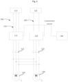
Fig. 2 is a schematic structural diagram of a rail vehicle ventilation system according to some embodiments of the present disclosure; -
Fig. 3 is a schematic block diagram of a flowchart of a control method for a rail vehicle ventilation system according to some embodiments of the present disclosure; and -
Fig. 4 is a schematic block diagram of a flowchart of a control method for a rail vehicle ventilation system according to some embodiments of the present disclosure. - In the drawings: 100. Rail vehicle ventilation system; 110. Main power supply line; 111. Ventilator inverter; 112. First switch; 113. Power source of the main power supply line; 120. Backup storage battery power supply line; 121. Storage battery power source; 122. Emergency ventilation inverter; 123. Second switch; 130. Ventilator; 140. Controller.
- It should be noted that these accompanying drawings and textual description are not intended to limit the scope of concept of the present disclosure in any way, but to illustrate the concept of the present disclosure for a person skilled in the art by reference to specific embodiments.
- In order to make objects, technical solutions and advantages of embodiments of the present disclosure clearer, hereinafter, the technical solutions in the embodiments will be clearly and completely described in combination with the accompanying drawings in the embodiments of the present disclosure. The following embodiments are used to illustrate the present disclosure, but are not intended to limit the scope of the present disclosure.
- In the illustration of the present disclosure, it should be noted that orientation or position relationships indicated by terms such as "upper", "lower", "front", "rear", "left", "right", "vertical", "inner", "outer", etc. are orientation or position relationships based on the accompanying drawings, and are only used to facilitate the illustration of the present disclosure and to simplify the illustration, rather than indicating or implying that a device or element referred to must have a specific orientation, and be constructed and operated in the specific orientation, and therefore said terms cannot be understood as limitation to the present disclosure.
- In the illustration of the present disclosure, it should be noted that unless otherwise explicitly specified and limited, terms "mount", "connect to", and "connecting" should be understood broadly, and for example, may be fixed connection, and may also be detachable connection, or integral connection; may be mechanical connection, and may also be electrical connection; and may be direct connection, and may also be indirect connection by means of an intermediate medium. For a person of ordinary skill in the art, the specific meanings of the described terms in the present disclosure could be understood according to specific situations.
- Hereinafter, the present disclosure will be further described in detail in combination with the embodiments.
- As shown in
Figs. 1 and2 , the present embodiment provides a control method for a railvehicle ventilation system 100; wherein the railvehicle ventilation system 100 includes a mainpower supply line 110 and a backup storage batterypower supply line 120; the mainpower supply line 110 has aventilator inverter 111, and the backup storage batterypower supply line 120 has anemergency ventilation inverter 122. - Specifically, the main
power supply line 110 includes apower source 113 of the main power supply line, specifically, thepower source 113 of the main power supply line is an alternating-current power source, thepower source 113 of the main power supply line is electrically connected to theventilator inverter 111, and theventilator inverter 111 is electrically connected toventilators 130; wherein afirst switch 112 is arranged on a line between theventilator inverter 111 and theventilators 130, and thefirst switch 112 is configured to control connection or disconnection between theventilator inverter 111 and theventilators 130. - The backup storage battery
power supply line 120 includes a storagebattery power source 121 and anemergency ventilation inverter 122, wherein the storagebattery power source 121 is electrically connected to theemergency ventilation inverter 122, and is boosted and inverted by theemergency ventilation inverter 122 and then converted into an alternating-current, and theemergency ventilation inverter 122 is electrically connected to theventilators 130; wherein asecond switch 123 is arranged on a line between theemergency ventilation inverter 122 and theventilators 130, and thesecond switch 123 is configured to control connection or disconnection between theemergency ventilation inverter 122 and theventilators 130. - The main
power supply line 110 and the backup storage batterypower supply line 120 are connected in parallel. - The rail
vehicle ventilation system 100 further includes acontroller 140; thecontroller 140 is respectively electrically connected to the mainpower supply line 110 and the backup storage batterypower supply line 120, and is configured to be able to respectively control thefirst switch 112, thesecond switch 123, theventilator inverter 111, the storagebattery power source 121, theemergency ventilation inverter 122, etc. - As shown in
Fig. 1 , the control method includes the following steps: - S101: whether the
ventilator inverter 111 failure is locked is determined; - S102: if the
ventilator inverter 111 failure is not locked, or maintaining the mainpower supply line 110 is turned on or maintained, and the mainpower supply line 110 to supply power to theventilators 130 via theventilator inverter 111 is controlled; and - S103: if the
ventilator inverter 111 failure is locked, the backup storage batterypower supply line 120 is turned on, and the backup storage batterypower supply line 120 is controlled to boost and invert the storagebattery power source 121 via theemergency ventilation inverter 122 and then power is supplied to theventilators 130. - In the present embodiment, by improving the design of a control function of the rail
vehicle ventilation system 100, when the ventilation function fails for some reasons, the ventilation system enters an emergency ventilation operation mode autonomously, so as to provide an alternating-current power source for theventilators 130, and theventilators 130 can start and operate, and thus a compressor and a condensate fan can start and operate to achieve heating and cooling air conditioning, thereby effectively improving the reliability of the air conditioning unit and the comfort of passengers. - In some embodiments, the step S101 of whether the
ventilator inverter 111 failure is locked is determined specifically includes: - working state information of the
ventilator inverter 111 is acquired; - whether the working state information satisfies a failure locking condition is determined; and
- if it is determined that the working state signal satisfies the failure locking condition, the
ventilator inverter 111 failure is locked is determined. - In some embodiments, the failure locking condition includes: whether a failure duration of the
ventilator inverter 111 exceeds a preset duration is determined. - In the present embodiment, when the
ventilator inverter 111 fails and the failure duration reaches the preset duration, it is determined that theventilator inverter 111 failure is locked, thereby effectively avoiding the problem of misjudgment caused by detection errors, environmental factors, etc., ensuring the accuracy of detection and determination, and improving the system reliability. - Preferably, the preset duration is 3 - 7 minutes.
- Preferably, the preset duration is 5 minutes.
- In some other embodiments, the failure locking condition includes: whether the number of failures of the
ventilator inverter 111 reaches a preset number is determined. - In the present embodiment, when the
ventilator inverter 111 fails and the number of failures reaches a preset number, it is determined that theventilator inverter 111 failure is locked, thereby effectively avoiding the problem of misjudgment caused by detection errors, environmental factors, etc., ensuring the accuracy of detection and determination, and improving the system reliability. - Preferably, the preset number of times is 2 - 6.
- Preferably, the preset number of times is 3.
- Of course, a person skilled in the art could understand that the two failure locking conditions do not conflict with each other. In some embodiments, the system can be designed to perform determination according to the two determination conditions, and when any one of the two determination conditions is satisfied, it can be determined that the
ventilator inverter 111 failure is locked. - In some embodiments, working state information of the
ventilator inverter 111 is acquired specifically includes: - a working state signal of the
ventilator inverter 111 is collected in real time; - according to the collected working state signal of the
ventilator inverter 111, whether there is a failure in theventilator inverter 111 is determined; - if there is the failure in the
ventilator inverter 111, theventilator inverter 111 is suspended; otherwise, theventilator inverter 111 is turned on or maintained, such that the mainpower supply line 110 supplies power to theventilators 130 via theventilator inverter 111 - After the
ventilator inverter 111 is suspended, the working state information is generated. - In the present embodiment, the working state signal of the
ventilator inverter 111 is collected in real time; when theventilator inverter 111 fails is collected, theventilator inverter 111 is suspended; and when theventilator inverter 111 is normal is collected, theventilator inverter 111 is turned on or continuously maintained, thereby ensuring normal working of theventilator inverter 111. - In some embodiments, before the working state information is generated, the method further includes:
- whether the failure of the
ventilator inverter 111 has been cleared is determined; - if the failure of the
ventilator inverter 111 has been cleared, the mainpower supply line 110 is turned on; - otherwise, the failure is timed, and the number of failures of the
ventilator inverter 111 are increased by one; and - working state information is generated according to the failure duration and an accumulated number of failures.
- In the present embodiment, upon detection that the
ventilator inverter 111 fails, continuing to detect theventilator inverter 111 in real time; upon detection that the failure of theventilator inverter 111 has been cleared, it indicates that the previous detection may be wrong, and theventilator inverter 111 has no failure, then the mainpower supply line 110 is turned on again, so that the mainpower supply line 110 supplies power to theventilator inverter 111, thereby ensuring normal working of theventilator inverter 111. - In some embodiments, if the working state information does not satisfy the failure locking condition, continuing to determine whether the failure of the
ventilator inverter 111 has been cleared. - In some embodiments, the rail
vehicle ventilation system 100 further has an air conditioning unit, and the air conditioning unit includes a fresh air damper and an return air damper, wherein
after the backup storage batterypower supply line 120 is turned on and the backup storage batterypower supply line 120 is controlled to boost and invert the storagebattery power source 121 via theemergency ventilation inverter 122 and then power is supplied to theventilators 130, an opening degree of the fresh air damper is controlled to be increased, and an opening degree of the return air damper is controlled to be decreased or closed. - In the present embodiment, the
ventilator inverter 111 fails, and thus the backup storage batterypower supply line 120 is turned on to supply power to theventilators 130. As the power supply capability of the backup storage batterypower supply line 120 is limited, the opening degree of the fresh air damper is controlled to be increased, and the opening degree of the return air damper is controlled to be decreased or closed, so as to ensure the ventilation effect. - In some embodiments, the method further includes:
- whether the
power source 113 of the main power supply line fails is determined; and - if the
power source 113 of the main power supply line fails, the backup storage batterypower supply line 120 is turned on, and the backup storage batterypower supply line 120 is controlled to boost and invert the storagebattery power source 121 via theemergency ventilation inverter 122 and then power to theventilators 130 is supplied. - In the present embodiment, upon detection that the
power source 113 of the main power supply line fails, the backup storage batterypower supply line 120 can also be enabled and the backup storage batterypower supply line 120 is controlled to supply power to theventilators 130, thereby ensuring normal working of theventilators 130. - In some specific embodiments, as shown in
Fig. 4 , a control method for a railvehicle ventilation system 100 includes the following steps: - the
ventilator inverter 111 is detected; - whether the
ventilator inverter 111 has no failure is determined; - if it is determined that the
ventilator inverter 111 has no failure, working of theventilator inverter 111 is started/maintained; - if it is determined that the
ventilator inverter 111 fails, working of theventilator inverter 111 is suspended; - the
ventilator inverter 111 is detected again, and whether the failure of theventilator inverter 111 has been cleared is determined; - if it is determined that the failure of the
ventilator inverter 111 has been cleared, working of theventilator inverter 111 is started/maintained; - otherwise, accumulatively the number of failures of the
ventilator inverter 111 are increased by one, and timing is performed; - the number of failures of the
ventilator inverter 111 is greater than 3 or the failure lasts for more than 5 minutes is determined; - if so, failure locking is performed and notified; and if not, continue to determine whether the failure of the
ventilator inverter 111 has been cleared is returned to. - In some other specific embodiments, as shown in
Fig. 3 , a control method for a railvehicle ventilation system 100 includes the following steps: - whether the
ventilator inverter 111 failure is locked is determined; - if the
ventilator inverter 111 failure is locked, thesecond switch 123 is closed, theemergency ventilation inverter 122 is started, and the fresh air damper is completely opened, and the return air damper is completely closed; - otherwise, whether the
ventilator inverter 111 has no failure is determined; - if the
ventilator inverter 111 has no failure, thefirst switch 112 is closed, and theventilator inverter 111 is started; and - otherwise, the
first switch 112 is opened and theventilator inverter 111 is stopped. - Further, continuing to determine whether the number of failures of the
ventilator inverter 111 is greater than or equal to 3; - if so, failure locking on the
ventilator inverter 111 is performed; otherwise, whether the failure of theventilator inverter 111 has been cleared is determined; - if the failure of the
ventilator inverter 111 has been cleared, the number of failures are increased by 1, thefirst switch 112 is closed, and theventilator inverter 111 is started; otherwise, whether the failure of theventilator inverter 111 has lasted for 5 minutes is determined; - if the failure of the
ventilator frequency ventilator 111 has lasted for 5 minutes, failure locking on theventilator frequency ventilator 111 is performed; otherwise, continue to determine whether the failure of theventilator frequency ventilator 111 has been cleared is returned to. - Further, an air conditioner to determine to perform cooling/heating is controlled according to an external environment temperature;
whether theventilators 130 operate is determined, if so, the compressor to operate is controlled, and the frequency of the compressor is adjusted; then the condenser fan to operate is controlled; and then, the opening degrees of the air valves is adjusted according to a load. - Otherwise, the compressor to stop operation is controlled; the condenser fan to stop operation is controlled; and the air valves to close is controlled.
- The present disclosure further provides a rail
vehicle ventilation system 100, including: - a main
power supply line 110, having aventilator inverter 111; - a backup storage battery
power supply line 120; -
ventilators 130, wherein the mainpower supply line 110 and the backup storage batterypower supply line 120 are respectively electrically connected to theventilators 130, and the mainpower supply line 110 and the backup storage batterypower supply line 120 are connected in parallel; and - a
controller 140, for executing the steps of the control method for the railvehicle ventilation system 100 according to any one of the described technical solutions. - The present disclosure further provides a rail vehicle, including: the rail
vehicle ventilation system 100 according to the described technical solutions. - In some specific embodiments of the present disclosure,
as shown inFig. 1 to Fig. 4 , the present embodiment provides a railvehicle ventilation system 100; the railvehicle ventilation system 100 includes a mainpower supply line 110, a backup storage batterypower supply line 120, and twoventilators 130, wherein the mainpower supply line 110 has aventilator inverter 111. - Specifically, the main
power supply line 110 includes an alternating-current power source, the alternating-current power source is electrically connected to theventilator inverter 111, and theventilator inverter 111 is electrically connected to theventilators 130; wherein a first control switch is arranged on a line between theventilator inverter 111 and theventilators 130, and the first control switch is configured to control connection or disconnection between theventilator inverter 111 and theventilators 130. - The backup storage battery
power supply line 120 includes astorage battery 121 power source and anemergency ventilation inverter 122, wherein thestorage battery 121 power source is electrically connected to theemergency ventilation inverter 122, and is converted into an alternating-current via theemergency ventilation inverter 122, and theemergency ventilation inverter 122 is electrically connected to theventilators 130; wherein a second control switch is arranged on a line between theemergency ventilation inverter 122 and theventilators 130, and the second control switch is configured to control connection or disconnection between theemergency ventilation inverter 122 and theventilators 130. - The main
power supply line 110 and the backup storage batterypower supply line 120 are connected in parallel. - The rail
vehicle ventilation system 100 further includes acontroller 140. Thecontroller 140 is respectively electrically connected to the mainpower supply line 110 and the backup storage batterypower supply line 120, and is configured to be able to control the first control switch and the second control switch respectively. - Specifically, the
air conditioning controller 140 collects a state signal of theventilator inverter 111, and monitors in real time whether a working state of the inverter is normal. - Upon detection that the
ventilator inverter 111 is normal, theair conditioning controller 140 controls thefirst switch 112 to be closed, controls theventilator inverter 111 to be started, such that the twoventilators 130 operate. - Upon detection that the
ventilator inverter 111 fails, theair conditioning controller 140 controls thefirst switch 112 to be opened, and controls frequency conversion boards of theventilators 130 to stop operating. - Upon detection that the failure of the
ventilator inverter 111 has been cleared, theair conditioning controller 140 closes thefirst switch 112 again, and starts the frequency conversion boards of theventilators 130; and upon detection that an accumulated number of failures of the frequency conversion boards of theventilators 130 reaches 3 times, theair conditioning controller 140 performs failure locking on the frequency conversion boards of theventilators 130, and reports failure information of theventilator inverter 111 to a driver's cab. - Upon detection that the failure of the frequency conversion boards of the
ventilators 130 lasts for 5 minutes and has not been cleared, theair conditioning controller 140 performs failure locking on the frequency conversion boards of theventilators 130, and reports failure information of theventilator inverter 111 to the driver's cabin. - After confirming that the
ventilator inverter 111 failure is locked, theair conditioning controller 140 controls thesecond switch 123 to be closed, starts theemergency ventilation inverter 122, such that the twoventilators 130 continue to operate. - After starting the
ventilators 130, the compressor and the condenser fan are allowed to start, and the air conditioner is allowed to enter a cooling/heating mode to operate. - In this case, the fresh air damper and the return air damper of the air conditioning unit automatically adjust the opening degrees of the air valves according to a passenger capacity signal, so as to provide ventilation for a carriage.
- In this case, the compressor may operate in a full frequency band according to the operation states of the
ventilators 130, or may operate at the maximum frequency defined as half the rated frequency according to program setting. The air conditioner keeps certain cooling or heating capacity, and provides cooling or heating for the carriage, so that the reliability of the air conditioning system is comprehensively improved. - The air conditioner automatically performs mode setting according to the environment temperature, enters a cooling/heating mode to operate, and provides air conditioning for the carriage, thereby improving the comfort of passengers and improving the reliability of the air conditioning unit.
- The contents above are only preferred embodiments of the present disclosure, and are not intended to limit the present disclosure in any form. The present disclosure has been disclosed in the preferred embodiments, but the preferred embodiments are not used to limit the present disclosure. Any person skilled in the art could make some changes or modifications by using the technical contents prompted above to obtain equivalent embodiments having equivalent variations without departing from the scope of the technical solutions of present disclosure. However, any contents without departing from the technical solutions of the present disclosure and any simple modifications, equivalent variations and modifications made to the described embodiments according to the technical essence of the present disclosure still belong to the scope of the solutions of the present disclosure.
Claims (10)
- A control method for a rail vehicle ventilation system, wherein the rail vehicle ventilation system comprises a main power supply line and a backup storage battery power supply line, the main power supply line is provided with a ventilator inverter, and the backup storage battery power supply line is provided with an emergency ventilation inverter, and the control method comprises the following steps:determining whether the ventilator inverter failure is locked;in a case where the ventilator inverter failure is not locked, turning on or maintaining the main power supply line and controlling the main power supply line to supply power to ventilators via the ventilator inverter; andin a case where the ventilator inverter failure is locked, turning on the backup storage battery power supply line and controlling the backup storage battery power supply line to boost and invert a storage battery power source via the emergency ventilation inverter and then supplying power to the ventilators.
- The control method for a rail vehicle ventilation system according to claim 1, wherein determining whether the ventilator inverter failure is locked specifically comprises:acquiring working state information of the ventilator inverter;determining whether the working state information satisfies a failure locking condition; andin a case where the working state signal satisfies the failure locking condition, determining that the ventilator inverter failure is locked.
- The control method for a rail vehicle ventilation system according to claim 2, wherein the failure locking condition comprises at least one of the following:determining whether a failure duration of the ventilator inverter exceeds a preset duration; anddetermining whether the number of failures of the ventilator inverter reaches a preset number.
- The control method for a rail vehicle ventilation system according to claim 2 or 3, wherein acquiring working state information of the ventilator inverter specifically comprises:collecting a working state signal of the ventilator inverter in real time;according to the collected working state signal of the ventilator inverter, determining whether there is a failure in the ventilator inverter;in a case where there is the failure in the ventilator inverter, suspending the ventilator inverter; otherwise, turning on or maintaining the ventilator inverter, so that the main power supply line supplies power to the ventilators via the ventilator inverter; andafter suspending the ventilator inverter, generating the working state information.
- The control method for a rail vehicle ventilation system according to claim 4, wherein before generating the working state information, the method further comprises:determining whether the failure of the ventilator inverter has been cleared;in a case where the failure of the ventilator inverter has been cleared, turning on the main power supply line;in a case where the failure of the ventilator inverter has not been cleared, timing the failure, and increasing the number of failures of the ventilator inverter by one; andgenerating the working state information according to the failure duration and an accumulated number of failures.
- The control method for a rail vehicle ventilation system according to claim 5, wherein
in a case where the working state information does not satisfy the failure locking condition, continuing to determine whether the failure of the ventilator inverter has been cleared. - The control method for a rail vehicle ventilation system according to any one of claims 1-3, wherein the rail vehicle ventilation system further comprises an air conditioning unit, and the air conditioning unit comprises a fresh air damper and an return air damper, wherein
after the backup storage battery power supply line is turned on and the backup storage battery power supply line is controlled to boost and invert the storage battery power source via the emergency ventilation inverter and then power is supplied to the ventilators, an opening degree of the fresh air damper is controlled to be increased, and an opening degree of the return air damper is controlled to be decreased or closed. - The control method for a rail vehicle ventilation system according to any one of claims 1-3, wherein the method further comprises:determining whether a power source of the main power supply line fails; andin a case where the power source of the main power supply line fails, turning on the backup storage battery power supply line and controlling the backup storage battery power supply line to boost and invert the storage battery power source via the emergency ventilation inverter and then supplying power to the ventilators.
- A rail vehicle ventilation system, comprising:a main power supply line, having a ventilator inverter;a backup storage battery power supply line, having an emergency ventilation inverter;at least one ventilator, wherein the main power supply line and the backup storage battery power supply line are respectively electrically connected to the ventilator, and the main power supply line and the backup storage battery power supply line are connected in parallel; anda controller, for executing the steps of the control method for the rail vehicle ventilation system according to any one of claims 1-8.
- A rail vehicle, comprising:
a rail vehicle ventilation system according to claim 9.
Applications Claiming Priority (2)
| Application Number | Priority Date | Filing Date | Title |
|---|---|---|---|
| CN202011391963.0A CN114572262A (en) | 2020-12-01 | 2020-12-01 | Rail vehicle, rail vehicle ventilation system and control method thereof |
| PCT/CN2021/134855 WO2022117008A1 (en) | 2020-12-01 | 2021-12-01 | Rail vehicle, and rail vehicle ventilation system and control method therefor |
Publications (2)
| Publication Number | Publication Date |
|---|---|
| EP4242084A1 true EP4242084A1 (en) | 2023-09-13 |
| EP4242084A4 EP4242084A4 (en) | 2024-04-24 |
Family
ID=81768655
Family Applications (1)
| Application Number | Title | Priority Date | Filing Date |
|---|---|---|---|
| EP21900034.6A Pending EP4242084A4 (en) | 2020-12-01 | 2021-12-01 | RAIL VEHICLE, AND RAIL VEHICLE VENTILATION SYSTEM AND CONTROL METHOD THEREFOR |
Country Status (3)
| Country | Link |
|---|---|
| EP (1) | EP4242084A4 (en) |
| CN (1) | CN114572262A (en) |
| WO (1) | WO2022117008A1 (en) |
Families Citing this family (1)
| Publication number | Priority date | Publication date | Assignee | Title |
|---|---|---|---|---|
| CN115520169B (en) * | 2022-11-01 | 2026-03-27 | 南京中车浦镇海泰制动设备有限公司 | An adaptive variable frequency control method and system for air supply device of rail transit vehicle |
Family Cites Families (12)
| Publication number | Priority date | Publication date | Assignee | Title |
|---|---|---|---|---|
| US4006603A (en) * | 1975-06-13 | 1977-02-08 | Vapor Corporation | Air conditioning system for a railway vehicle |
| JPH07194187A (en) * | 1993-12-28 | 1995-07-28 | Toshiba Corp | Vehicle air conditioning controller |
| KR100250612B1 (en) * | 1997-12-11 | 2000-04-01 | 추호석 | Operation circuit system of unit fan for railway vehicle |
| CN101251286B (en) * | 2007-02-02 | 2011-04-20 | 山东朗进科技股份有限公司 | System and method for controlling emergency draft of air conditioner |
| CN202338982U (en) * | 2011-12-15 | 2012-07-18 | 长春研奥电器有限公司 | Metro vehicle air conditioning control system |
| CN108347202B (en) * | 2017-01-23 | 2021-04-13 | 宝山钢铁股份有限公司 | A method for resisting voltage sag of inverter for large-capacity fan |
| CN108621797B (en) * | 2017-03-20 | 2020-06-05 | 克诺尔轨道车辆技术(上海)有限公司 | Rail vehicle and power supply system and variable frequency air conditioning system thereof |
| CN207889713U (en) * | 2018-02-05 | 2018-09-21 | 山东朗进科技股份有限公司 | A kind of fresh air system of railway vehicle air conditioner |
| JP6983697B2 (en) * | 2018-03-09 | 2021-12-17 | 三菱電機株式会社 | Air conditioner for railway vehicles |
| CN108880229A (en) * | 2018-08-24 | 2018-11-23 | 张立明 | A kind of train emergency ventilation inverter |
| CN210591892U (en) * | 2019-08-10 | 2020-05-22 | 中车青岛四方机车车辆股份有限公司 | A rail vehicle emergency ventilation system and rail vehicle |
| CN111648993B (en) * | 2020-06-10 | 2022-04-19 | 广东萨米特陶瓷有限公司 | Control system and method for intelligent standby system of kiln fan |
-
2020
- 2020-12-01 CN CN202011391963.0A patent/CN114572262A/en active Pending
-
2021
- 2021-12-01 WO PCT/CN2021/134855 patent/WO2022117008A1/en not_active Ceased
- 2021-12-01 EP EP21900034.6A patent/EP4242084A4/en active Pending
Also Published As
| Publication number | Publication date |
|---|---|
| WO2022117008A1 (en) | 2022-06-09 |
| CN114572262A (en) | 2022-06-03 |
| EP4242084A4 (en) | 2024-04-24 |
Similar Documents
| Publication | Publication Date | Title |
|---|---|---|
| US10857903B2 (en) | Power control system for electric vehicle | |
| US12576688B2 (en) | Climate controlled vehicle, transport climate control equipment, method of retrofitting a vehicle and method of operation | |
| CN111137105A (en) | A new energy vehicle integrated thermal management control system and control method thereof | |
| US20150191073A1 (en) | Method and vehicle for operating a vehicle air conditioning system | |
| CN107914541B (en) | Integrated control method and system for motor of electric vehicle | |
| EP2120331A1 (en) | Inverter system for vehicle-mounted air conditioner | |
| CN108162723B (en) | Air conditioning system of electric motor coach and frequency converter thereof | |
| CN108626856B (en) | Control method and control device for air conditioning equipment, storage medium and air conditioning equipment | |
| CN114619870B (en) | A grille control method, device, equipment and medium | |
| WO2022117008A1 (en) | Rail vehicle, and rail vehicle ventilation system and control method therefor | |
| JP2010181126A (en) | Refrigerating device for trailer | |
| CN103883544A (en) | Control method and control device for engine cooling fan | |
| KR102042322B1 (en) | Engine control method for heating of hybrid electric vehicle | |
| CN115571192B (en) | Integrated control architecture and device control method based on the integrated control architecture | |
| CN114572261A (en) | Rail vehicle, rail vehicle air conditioning system and control method thereof | |
| KR102402552B1 (en) | Electric Refrigenating System | |
| JP6566713B2 (en) | Air conditioner for vehicles | |
| CN116080341A (en) | Integrated electric air conditioning control method and system for commercial vehicles | |
| CN116442728A (en) | Control method for parking air conditioner, controller and parking air conditioner | |
| CN113419577B (en) | Temperature control method | |
| CN113548074A (en) | Fault Monitoring System for Airtightness Control of Dual-flow Vehicles | |
| KR20220117419A (en) | Electric Refrigenating System | |
| JP2016013729A (en) | Vehicle air conditioning control device | |
| CN114571947B (en) | Integrated air conditioning system and control method for battery cooling and passenger cooling | |
| JP2016110954A (en) | Air-conditioning system |
Legal Events
| Date | Code | Title | Description |
|---|---|---|---|
| STAA | Information on the status of an ep patent application or granted ep patent |
Free format text: STATUS: THE INTERNATIONAL PUBLICATION HAS BEEN MADE |
|
| PUAI | Public reference made under article 153(3) epc to a published international application that has entered the european phase |
Free format text: ORIGINAL CODE: 0009012 |
|
| STAA | Information on the status of an ep patent application or granted ep patent |
Free format text: STATUS: REQUEST FOR EXAMINATION WAS MADE |
|
| 17P | Request for examination filed |
Effective date: 20230606 |
|
| AK | Designated contracting states |
Kind code of ref document: A1 Designated state(s): AL AT BE BG CH CY CZ DE DK EE ES FI FR GB GR HR HU IE IS IT LI LT LU LV MC MK MT NL NO PL PT RO RS SE SI SK SM TR |
|
| DAV | Request for validation of the european patent (deleted) | ||
| DAX | Request for extension of the european patent (deleted) | ||
| A4 | Supplementary search report drawn up and despatched |
Effective date: 20240325 |
|
| RIC1 | Information provided on ipc code assigned before grant |
Ipc: B60R 16/03 20060101ALI20240319BHEP Ipc: B61D 27/00 20060101AFI20240319BHEP |
|
| STAA | Information on the status of an ep patent application or granted ep patent |
Free format text: STATUS: EXAMINATION IS IN PROGRESS |
|
| 17Q | First examination report despatched |
Effective date: 20251203 |