EP4242026A1 - Road vehicle provided with an air conditioning system of the passenger compartment - Google Patents
Road vehicle provided with an air conditioning system of the passenger compartment Download PDFInfo
- Publication number
- EP4242026A1 EP4242026A1 EP23160888.6A EP23160888A EP4242026A1 EP 4242026 A1 EP4242026 A1 EP 4242026A1 EP 23160888 A EP23160888 A EP 23160888A EP 4242026 A1 EP4242026 A1 EP 4242026A1
- Authority
- EP
- European Patent Office
- Prior art keywords
- air
- blade
- road vehicle
- bifurcation
- passenger compartment
- Prior art date
- Legal status (The legal status is an assumption and is not a legal conclusion. Google has not performed a legal analysis and makes no representation as to the accuracy of the status listed.)
- Granted
Links
Images



Classifications
-
- B—PERFORMING OPERATIONS; TRANSPORTING
- B60—VEHICLES IN GENERAL
- B60H—ARRANGEMENTS OF HEATING, COOLING, VENTILATING OR OTHER AIR-TREATING DEVICES SPECIALLY ADAPTED FOR PASSENGER OR GOODS SPACES OF VEHICLES
- B60H1/00—Heating, cooling or ventilating devices
- B60H1/34—Nozzles; Air-diffusers
- B60H1/3414—Nozzles; Air-diffusers with means for adjusting the air stream direction
-
- B—PERFORMING OPERATIONS; TRANSPORTING
- B60—VEHICLES IN GENERAL
- B60H—ARRANGEMENTS OF HEATING, COOLING, VENTILATING OR OTHER AIR-TREATING DEVICES SPECIALLY ADAPTED FOR PASSENGER OR GOODS SPACES OF VEHICLES
- B60H1/00—Heating, cooling or ventilating devices
- B60H1/00007—Combined heating, ventilating, or cooling devices
- B60H1/00021—Air flow details of HVAC devices
- B60H1/00028—Constructional lay-out of the devices in the vehicle
-
- B—PERFORMING OPERATIONS; TRANSPORTING
- B60—VEHICLES IN GENERAL
- B60H—ARRANGEMENTS OF HEATING, COOLING, VENTILATING OR OTHER AIR-TREATING DEVICES SPECIALLY ADAPTED FOR PASSENGER OR GOODS SPACES OF VEHICLES
- B60H1/00—Heating, cooling or ventilating devices
- B60H1/00271—HVAC devices specially adapted for particular vehicle parts or components and being connected to the vehicle HVAC unit
- B60H1/00285—HVAC devices specially adapted for particular vehicle parts or components and being connected to the vehicle HVAC unit for vehicle seats
-
- B—PERFORMING OPERATIONS; TRANSPORTING
- B60—VEHICLES IN GENERAL
- B60H—ARRANGEMENTS OF HEATING, COOLING, VENTILATING OR OTHER AIR-TREATING DEVICES SPECIALLY ADAPTED FOR PASSENGER OR GOODS SPACES OF VEHICLES
- B60H1/00—Heating, cooling or ventilating devices
- B60H1/00642—Control systems or circuits; Control members or indication devices for heating, cooling or ventilating devices
- B60H1/00664—Construction or arrangement of damper doors
- B60H1/00671—Damper doors moved by rotation; Grilles
-
- B—PERFORMING OPERATIONS; TRANSPORTING
- B60—VEHICLES IN GENERAL
- B60H—ARRANGEMENTS OF HEATING, COOLING, VENTILATING OR OTHER AIR-TREATING DEVICES SPECIALLY ADAPTED FOR PASSENGER OR GOODS SPACES OF VEHICLES
- B60H1/00—Heating, cooling or ventilating devices
- B60H1/24—Ventilating devices where the heating or cooling is irrelevant
- B60H1/241—Ventilating devices where the heating or cooling is irrelevant characterised by the location of ventilation devices in the vehicle
- B60H1/246—Ventilating devices where the heating or cooling is irrelevant characterised by the location of ventilation devices in the vehicle located in the interior of the vehicle or in or below the floor
-
- B—PERFORMING OPERATIONS; TRANSPORTING
- B60—VEHICLES IN GENERAL
- B60H—ARRANGEMENTS OF HEATING, COOLING, VENTILATING OR OTHER AIR-TREATING DEVICES SPECIALLY ADAPTED FOR PASSENGER OR GOODS SPACES OF VEHICLES
- B60H1/00—Heating, cooling or ventilating devices
- B60H1/00007—Combined heating, ventilating, or cooling devices
- B60H1/00021—Air flow details of HVAC devices
- B60H2001/00078—Assembling, manufacturing or layout details
- B60H2001/00092—Assembling, manufacturing or layout details of air deflecting or air directing means inside the device
-
- B—PERFORMING OPERATIONS; TRANSPORTING
- B60—VEHICLES IN GENERAL
- B60H—ARRANGEMENTS OF HEATING, COOLING, VENTILATING OR OTHER AIR-TREATING DEVICES SPECIALLY ADAPTED FOR PASSENGER OR GOODS SPACES OF VEHICLES
- B60H1/00—Heating, cooling or ventilating devices
- B60H1/00007—Combined heating, ventilating, or cooling devices
- B60H1/00021—Air flow details of HVAC devices
- B60H2001/00185—Distribution of conditionned air
- B60H2001/00192—Distribution of conditionned air to left and right part of passenger compartment
-
- B—PERFORMING OPERATIONS; TRANSPORTING
- B60—VEHICLES IN GENERAL
- B60H—ARRANGEMENTS OF HEATING, COOLING, VENTILATING OR OTHER AIR-TREATING DEVICES SPECIALLY ADAPTED FOR PASSENGER OR GOODS SPACES OF VEHICLES
- B60H1/00—Heating, cooling or ventilating devices
- B60H1/34—Nozzles; Air-diffusers
- B60H2001/3471—Details of actuators
Definitions
- the present invention relates to a road vehicle provided with an air conditioning system of the passenger compartment.
- the air conditioning system for a passenger compartment of a road vehicle introduces treated (heated, cooled, dehumidified, and/or filtered) air into the passenger compartment according to the passengers' preferences.
- the air conditioning system comprises an air treatment unit, which is adapted to treat the air that is subsequently introduced into the passenger compartment through a series of air vents present in the passenger compartment itself.
- the patent application EP2500192A1 describes an air conditioning system of a vehicle comprising two central outlet vents and two lateral outlet vents arranged in the instrument panel. The adjustment of the flow rate of air flowing out of the four outlet vents is adjusted by three hinged blades.
- the patent application DE102018214560A1 describes an end part of an air conditioning system for a passenger compartment of a vehicle, in which two overlapping outlet vents are provided; the flow rate of air flowing out of the two overlapping outlet vents is adjusted by a hinged blade arranged upstream of the two outlet vents.
- the purpose of the present invention is to provide a road vehicle provided with an air conditioning system of the passenger compartment that is free of the drawbacks described above and is, at the same time, easy and inexpensive to produce.
- the number 1 denotes as a whole a road vehicle (in particular an automobile) provided with two driven (namely, non-driving) front wheels and with two driving rear wheels.
- An internal combustion engine is arranged in the front position, which produces torque that is transmitted to the driving wheels by means of a transmission.
- the road vehicle 1 comprises a passenger compartment 2 that is provided with multiple seats 3 each adapted to accommodate a corresponding occupant; namely, there is always a place for a driver in the passenger compartment 2 to which passengers can be added (whose presence is, of course, optional).
- the road vehicle 1 comprises an air conditioning system 4 provided with an air treatment unit 5 adapted to treat (heat, cool, dehumidify and/or filter) the air that must be introduced into the passenger compartment 2.
- An air treatment unit 5 adapted to treat (heat, cool, dehumidify and/or filter) the air that must be introduced into the passenger compartment 2.
- a plurality of air vents 6 are connected to the air treatment unit 5, which air vents have the function of introducing the air treated by the air treatment unit 5 into the passenger compartment 2 and are distributed within the passenger compartment 2 in order to be able to introduce the air into different areas of the passenger compartment 2 itself.
- two twin rear air vents 6 are arranged in front of the two rear seats 3 and in a central position (namely, in the area of the transmission tunnel T that is schematically illustrated in Figure 1 and runs longitudinally through the passenger compartment 2 from front to rear), which are arranged side by side and are directed one towards a right side of the passenger compartment 2 (namely, towards the right rear seat 3 and obviously arranged on the right side) and the other towards a left side of the passenger compartment 2 (namely, towards the left rear seat 3 and obviously arranged on the left side).
- the two rear air vents 6 are obtained in a rear body 7 arranged in the centre of the passenger compartment 2 in the area of the transmission tunnel T.
- the air treatment unit 5 is connected to the two rear air vents 6 to supply treated air to the two rear air vents 6 by means of a single common supply duct 8.
- the common supply duct 8 originates from the air treatment unit 5 and ends in a bifurcation 9 that has two branches 10, each of which is connected to a corresponding rear air vent 6.
- the bifurcation 9 connects the common supply duct 8 to the two rear air vents 6 and has a right branch 10 which ends in a right rear air vent 6 and a left branch 10 which ends in a left rear air vent 6.
- the air conditioning system 4 comprises a blade 11 that is arranged in the area of the bifurcation 9 and is mounted movably between a completely closed position (illustrated in Figures 5 and 8 ) of the right branch 10 of the bifurcation 9 (namely, the right rear air vent 6) and a completely closed position (illustrated in Figures 5 and 7 ) of the left branch 10 of the bifurcation 9 (namely, the left rear air vent 6).
- the blade 11 is hinged in order to rotate around a rotation axis 12 between the completely closed position of the right branch 10 and the completely closed position of the left branch 10.
- the air conditioning system 4 comprises an electric actuator 13 (illustrated in Figures 2 and 3 ) configured to move the blade 11 between the completely closed position of the right branch 10 and the completely closed position of the left branch 10.
- the electric actuator 13 is rotary and has a rotatable drive shaft that is angularly integral with a rotatable support shaft of the blade 11.
- the drive shaft of the electric actuator 13 may be coaxial and directly connected to the support shaft of the blade 11, or a mechanical gear transmission may be interposed between the drive shaft of the electric actuator 13 and the support shaft of the blade 11.
- the two branches 10 of the bifurcation 9 are separated from each other by a fixed dividing wall 14 and the blade 11 is hinged in the area of an initial end (edge) of the dividing wall 14.
- the dividing wall 14 is arranged downstream of the blade 11 with respect to the air flow namely it is arranged closer to the two rear air vents 6 than the blade 11.
- the common supply duct 8 has a vertically oriented end segment and the rotation axis 12 of the blade 11 is oriented horizontally and longitudinally (with respect to the road vehicle 1).
- the two branches 10 of the bifurcation 9 form a sharp bend so as to have a vertical orientation in the area of the blade 11 and a horizontal orientation in the area of the two rear air vents 6.
- the air conditioning system 4 comprises a control unit 15 that oversees the operation of the air conditioning system 4 and, among other things, drives the electric actuator 13 to establish the position of the blade 11.
- two twin control devices 16 are connected to the control unit 15, each of which is associated with a corresponding rear air vent 6 (therefore, is arranged in proximity to the corresponding rear air vent 6), is manually operable by a user to request the amount of treated air that has to flow out of the rear air vent 6, and is movable between a position of lack of aeration through the rear air vent 6 and a position of maximum aeration through the rear air vent 6.
- the control unit 15 is configured to establish the position of the blade 11 depending on the signals provided by the two control devices 16.
- a single control device 16 is present which is manually operable by a user to change the amount of treated air that has to flow out of the two rear air vents 6 and is movable between a left limit position in which the treated air only flows out of the left rear air vent 6 and a right limit position in which the treated air only flows out of the right rear air vent 6.
- the control unit 15 is configured to establish the position of the blade 11 depending on a signal provided by the single control device 16.
- control unit 15 is configured to establish the position of the blade 11 according to a combination of the signals provided by the two control devices 16; in other words, a combination is calculated between the signals provided by the two control devices 16 and the result of this combination provides the position of the blade 11.
- the blade 11 is positioned exactly in the centre between the two branches 10 of the bifurcation 9 (as illustrated in Figure 6 ), whereas if the signals of the two control devices 16 are not identical (i.e., they require different amounts of air), the blade 11 is positioned to divert more air towards the rear air vent 6 the control device 16 of which requires a greater amount of air and therefore to divert less air towards the rear air vent 6 the control device 16 of which requires a lesser amount of air (until the branch 10 of a rear air vent 6, the control device 16 of which requires a zero amount of air as illustrated in Figures 7 and 8 , is completely closed).
- control unit 15 is configured to establish a flow rate of the treated air supplied through the common supply duct 8 depending on the signals provided by the two control devices 16: if overall the signals provided by the two control devices 16 require more air, the flow rate of the treated air supplied through the common supply duct 8 is increased and vice versa.
- each control device 16 could provide a normalized signal comprised between 0 and 100, wherein 0 corresponds to the position of no air intake, and 100 corresponds to the position of maximum air intake.
- each control device 16 is of a rotary type and comprises a rotary knob 17 mounted rotatably between the position of lack of aeration through the corresponding rear air vent 6 and the position of maximum aeration through the corresponding rear air vent 6; a sensor 18 (an angular encoder) is provided that detects the angular position of the rotary knob 17 and transmits the angular position of the rotary knob 17 to the control unit 15.
- control unit 15, the electric actuator 13 and the control devices 16 communicate with each other by means of a BUS of the road vehicle 1 which, for example, could use the low-speed single-cable serial communication protocol called LIN ("Local Interconnect Network").
- LIN Low-speed single-cable serial communication protocol
- the air conditioning system 4 described above has several advantages.
- the air conditioning system 4 described above allows a completely independent adjustment of the treated air introduced by the two side by side air vents 6 arranged in front of the rear seats 3.
- the air conditioning system 4 described above does not pose any problems of space in the area of the transmission tunnel T since it requires the presence of a single common supply duct 8 which is arranged along the transmission tunnel T.
- the air conditioning system 4 described above is also particularly compact in the area of the two side by side air vents 6 arranged in front of the rear seats 3 to the benefit of the spaciousness of the rear seats 3.
Landscapes
- Engineering & Computer Science (AREA)
- Physics & Mathematics (AREA)
- Thermal Sciences (AREA)
- Mechanical Engineering (AREA)
- Power Engineering (AREA)
- Air-Conditioning For Vehicles (AREA)
Abstract
Description
- This application claims priority from the
Italian patent application no. 102022000004622 filed on March 10, 2022 - The present invention relates to a road vehicle provided with an air conditioning system of the passenger compartment.
- The air conditioning system for a passenger compartment of a road vehicle introduces treated (heated, cooled, dehumidified, and/or filtered) air into the passenger compartment according to the passengers' preferences. For this purpose, the air conditioning system comprises an air treatment unit, which is adapted to treat the air that is subsequently introduced into the passenger compartment through a series of air vents present in the passenger compartment itself.
- Generally, in order to be able to independently adjust the treated air introduced by two side by side air vents, two separate supply ducts are used, each of which originates from the air treatment unit and ends in a corresponding air vent. However, this solution poses major space problems in the case of the rear air vents in a front-engine and rear-wheel-drive vehicle as the available space along the transmission tunnel (which runs longitudinally through the road vehicle from the front to the rear) in which to position the two separate supply ducts is small.
- The patent application
EP2500192A1 describes an air conditioning system of a vehicle comprising two central outlet vents and two lateral outlet vents arranged in the instrument panel. The adjustment of the flow rate of air flowing out of the four outlet vents is adjusted by three hinged blades. - The patent application
DE102018214560A1 describes an end part of an air conditioning system for a passenger compartment of a vehicle, in which two overlapping outlet vents are provided; the flow rate of air flowing out of the two overlapping outlet vents is adjusted by a hinged blade arranged upstream of the two outlet vents. - The purpose of the present invention is to provide a road vehicle provided with an air conditioning system of the passenger compartment that is free of the drawbacks described above and is, at the same time, easy and inexpensive to produce.
- According to the present invention a road vehicle provided with an air conditioning system of the passenger compartment is provided, according to what is claimed by the appended claims.
- The claims describe preferred embodiments of the present invention forming an integral part of the present description.
- The present invention will now be described with reference to the appended drawings, which illustrate a non-limiting example embodiment thereof:
-
Figure 1 is a schematic view of an automobile provided with an air conditioning system and produced in accordance with the present invention; -
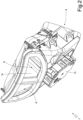
Figure 2 is a perspective view of a rear body of the air conditioning system ofFigure 1 ; -
Figure 3 is an exploded perspective view of the rear body ofFigure 2 ; -
Figure 4 is a sectional view with parts removed for clarity of the rear body ofFigure 2 ; -
Figure 5 is a sectional view with parts removed for clarity of a blade of the rear body ofFigure 2 in two different positions; and -
Figures 6, 7 and 8 schematically show three different configurations that the blade ofFigure 5 can assume during use. - In
Figure 1 , thenumber 1 denotes as a whole a road vehicle (in particular an automobile) provided with two driven (namely, non-driving) front wheels and with two driving rear wheels. An internal combustion engine is arranged in the front position, which produces torque that is transmitted to the driving wheels by means of a transmission. - The
road vehicle 1 comprises apassenger compartment 2 that is provided withmultiple seats 3 each adapted to accommodate a corresponding occupant; namely, there is always a place for a driver in thepassenger compartment 2 to which passengers can be added (whose presence is, of course, optional). - The
road vehicle 1 comprises an air conditioning system 4 provided with an air treatment unit 5 adapted to treat (heat, cool, dehumidify and/or filter) the air that must be introduced into thepassenger compartment 2. A plurality ofair vents 6 are connected to the air treatment unit 5, which air vents have the function of introducing the air treated by the air treatment unit 5 into thepassenger compartment 2 and are distributed within thepassenger compartment 2 in order to be able to introduce the air into different areas of thepassenger compartment 2 itself. - According to what is illustrated in
Figure 2 , two twinrear air vents 6 are arranged in front of the tworear seats 3 and in a central position (namely, in the area of the transmission tunnel T that is schematically illustrated inFigure 1 and runs longitudinally through thepassenger compartment 2 from front to rear), which are arranged side by side and are directed one towards a right side of the passenger compartment 2 (namely, towards the rightrear seat 3 and obviously arranged on the right side) and the other towards a left side of the passenger compartment 2 (namely, towards the leftrear seat 3 and obviously arranged on the left side). In particular, the tworear air vents 6 are obtained in arear body 7 arranged in the centre of thepassenger compartment 2 in the area of the transmission tunnel T. - According to what is illustrated in
Figure 4 , the air treatment unit 5 is connected to the tworear air vents 6 to supply treated air to the tworear air vents 6 by means of a singlecommon supply duct 8. Thecommon supply duct 8 originates from the air treatment unit 5 and ends in abifurcation 9 that has twobranches 10, each of which is connected to a correspondingrear air vent 6. Namely, thebifurcation 9 connects thecommon supply duct 8 to the tworear air vents 6 and has aright branch 10 which ends in a rightrear air vent 6 and aleft branch 10 which ends in a leftrear air vent 6. - The air conditioning system 4 comprises a
blade 11 that is arranged in the area of thebifurcation 9 and is mounted movably between a completely closed position (illustrated inFigures 5 and8 ) of theright branch 10 of the bifurcation 9 (namely, the right rear air vent 6) and a completely closed position (illustrated inFigures 5 and7 ) of theleft branch 10 of the bifurcation 9 (namely, the left rear air vent 6). According to a preferred embodiment, theblade 11 is hinged in order to rotate around arotation axis 12 between the completely closed position of theright branch 10 and the completely closed position of theleft branch 10. - The air conditioning system 4 comprises an electric actuator 13 (illustrated in
Figures 2 and3 ) configured to move theblade 11 between the completely closed position of theright branch 10 and the completely closed position of theleft branch 10. According to a preferred embodiment, theelectric actuator 13 is rotary and has a rotatable drive shaft that is angularly integral with a rotatable support shaft of theblade 11. In particular, the drive shaft of theelectric actuator 13 may be coaxial and directly connected to the support shaft of theblade 11, or a mechanical gear transmission may be interposed between the drive shaft of theelectric actuator 13 and the support shaft of theblade 11. - According to a preferred embodiment, the two
branches 10 of thebifurcation 9 are separated from each other by a fixed dividingwall 14 and theblade 11 is hinged in the area of an initial end (edge) of the dividingwall 14. In particular, the dividingwall 14 is arranged downstream of theblade 11 with respect to the air flow namely it is arranged closer to the tworear air vents 6 than theblade 11. - According to a preferred embodiment, the
common supply duct 8 has a vertically oriented end segment and therotation axis 12 of theblade 11 is oriented horizontally and longitudinally (with respect to the road vehicle 1). The twobranches 10 of thebifurcation 9 form a sharp bend so as to have a vertical orientation in the area of theblade 11 and a horizontal orientation in the area of the tworear air vents 6. - According to what is illustrated in
Figure 1 , the air conditioning system 4 comprises acontrol unit 15 that oversees the operation of the air conditioning system 4 and, among other things, drives theelectric actuator 13 to establish the position of theblade 11. According to what is illustrated inFigures 6, 7 and 8 , twotwin control devices 16 are connected to thecontrol unit 15, each of which is associated with a corresponding rear air vent 6 (therefore, is arranged in proximity to the corresponding rear air vent 6), is manually operable by a user to request the amount of treated air that has to flow out of therear air vent 6, and is movable between a position of lack of aeration through therear air vent 6 and a position of maximum aeration through therear air vent 6. Thecontrol unit 15 is configured to establish the position of theblade 11 depending on the signals provided by the twocontrol devices 16. - According to a different embodiment not illustrated, a
single control device 16 is present which is manually operable by a user to change the amount of treated air that has to flow out of the tworear air vents 6 and is movable between a left limit position in which the treated air only flows out of the leftrear air vent 6 and a right limit position in which the treated air only flows out of the rightrear air vent 6. Obviously, in this embodiment, thecontrol unit 15 is configured to establish the position of theblade 11 depending on a signal provided by thesingle control device 16. - According to a preferred embodiment, the
control unit 15 is configured to establish the position of theblade 11 according to a combination of the signals provided by the twocontrol devices 16; in other words, a combination is calculated between the signals provided by the twocontrol devices 16 and the result of this combination provides the position of theblade 11. If the signals of the twocontrol devices 16 are identical (i.e., they require the same amount of air, which may also be zero), theblade 11 is positioned exactly in the centre between the twobranches 10 of the bifurcation 9 (as illustrated inFigure 6 ), whereas if the signals of the twocontrol devices 16 are not identical (i.e., they require different amounts of air), theblade 11 is positioned to divert more air towards therear air vent 6 thecontrol device 16 of which requires a greater amount of air and therefore to divert less air towards therear air vent 6 thecontrol device 16 of which requires a lesser amount of air (until thebranch 10 of arear air vent 6, thecontrol device 16 of which requires a zero amount of air as illustrated inFigures 7 and 8 , is completely closed). - It is important to observe that, when the two signals of the two
control devices 16 are identical and both require the absence of air, theblade 11 is still positioned exactly in the centre between the twobranches 10 of the bifurcation 9 (as illustrated inFigure 6 ) as the two signals of the twocontrol devices 16 are identical (namely, there is no preference for one side over the other) and the absence of air is obtained upstream by acting on the air treatment unit 5 that no longer supplies air to thecommon supply duct 8. - According to a preferred embodiment, the
control unit 15 is configured to establish a flow rate of the treated air supplied through thecommon supply duct 8 depending on the signals provided by the two control devices 16: if overall the signals provided by the twocontrol devices 16 require more air, the flow rate of the treated air supplied through thecommon supply duct 8 is increased and vice versa. - By way of example, each
control device 16 could provide a normalized signal comprised between 0 and 100, wherein 0 corresponds to the position of no air intake, and 100 corresponds to the position of maximum air intake. - According to a preferred embodiment, each
control device 16 is of a rotary type and comprises arotary knob 17 mounted rotatably between the position of lack of aeration through the correspondingrear air vent 6 and the position of maximum aeration through the correspondingrear air vent 6; a sensor 18 (an angular encoder) is provided that detects the angular position of therotary knob 17 and transmits the angular position of therotary knob 17 to thecontrol unit 15. - According to a preferred embodiment, the
control unit 15, theelectric actuator 13 and thecontrol devices 16 communicate with each other by means of a BUS of theroad vehicle 1 which, for example, could use the low-speed single-cable serial communication protocol called LIN ("Local Interconnect Network"). - The air conditioning system 4 described above has several advantages.
- Firstly, the air conditioning system 4 described above allows a completely independent adjustment of the treated air introduced by the two side by
side air vents 6 arranged in front of therear seats 3. - In addition, the air conditioning system 4 described above does not pose any problems of space in the area of the transmission tunnel T since it requires the presence of a single
common supply duct 8 which is arranged along the transmission tunnel T. - Finally, the air conditioning system 4 described above is also particularly compact in the area of the two side by
side air vents 6 arranged in front of therear seats 3 to the benefit of the spaciousness of therear seats 3. -
- 1
- automobile
- 2
- passenger compartment
- 3
- seats
- 4
- air conditioning system
- 5
- air treatment unit
- 6
- air vents
- 7
- rear body
- 8
- supply duct
- 9
- bifurcation
- 10
- branches
- 11
- blade
- 12
- rotation axis
- 13
- electric actuator
- 14
- dividing wall
- 15
- control unit
- 16
- control device
- 17
- rotary knob
- 18
- sensor
- T
- transmission tunnel
Claims (11)
- A road vehicle (1) comprising: a passenger compartment (2) in which a transmission tunnel (T) is present, a right rear seat (3) and a left rear seat (3); and an air conditioning system (4) of the passenger compartment (2); the air conditioning system (4) comprises:a rear body (7) that is arranged in the centre of the passenger compartment (2) in the area of the transmission tunnel (T) and in front of the rear seats (3);two air vents (6) that are obtained in the rear body (7), are arranged side by side one on the right side of the passenger compartment (2) and the other on the left side of the passenger compartment (2), and are directed one towards the right rear seat (3) and the other towards the left rear seat (3);an air treatment unit (5) connected to the two air vents (6) in order to supply treated air to the two air vents (6);one single common supply duct (8), which originates from the air treatment unit (5); anda bifurcation (9), which connects the common supply duct (8) to the two air vents (6) and has a right branch (10), which ends in a right air vent (6), and a left branch (10), which ends in a left air vent (6);the road vehicle (1) is characterized in that it comprises:a blade (11), which is arranged in the area of the bifurcation (9) and is movable between a completely closed position of the right branch (10) of the bifurcation (9) and a completely closed position of the left branch (10) of the bifurcation (9); andan electric actuator (13) configured to move the blade (11) between the completely closed position of the right branch (10) and the completely closed position of the left branch (10).
- The road vehicle (1) according to claim 1, wherein the blade (11) is hinged so as to rotate around a rotation axis (12) between the completely closed position of the right branch (10) and the completely closed position of the left branch (10).
- The road vehicle (1) according to claim 2, wherein the common supply duct (8) has a vertically oriented end segment and the rotation axis (12) of the blade (11) is oriented horizontally and longitudinally.
- The road vehicle (1) according to claim 3, wherein the two branches (10) of the bifurcation (9) form a sharp bend so as to have a vertical orientation in the area of the blade (11) and a horizontal orientation in the area of the two air vents (6).
- The road vehicle (1) according to claim 2, 3 or 4, wherein the two branches (10) of the bifurcation (9) are separated from one another by a fixed dividing wall (14) and the blade (11) is hinged in the area of an initial end of the dividing wall (14).
- The road vehicle (1) according to claim 5, wherein the dividing wall (14) is arranged downstream of the blade (11) relative to the air flow.
- The road vehicle (1) according to one of the claims from 1 to 6 and comprising:one single control device (16), which can manually be operated by a user to request the quantity of treated air that has to flow out of the two air vents (6) and is movable between a left limit position, in which the treated air only flows out of the left air vent (6), and a right limit position, in which the treated air only flows out of the right air vent (6); anda control unit (15) configured to establish the position of the blade (11) depending on a signal provided by the control device (16) .
- The road vehicle (1) according to one of the claims from 1 to 6 and comprising:two control devices (16), each of which is associated with a corresponding air vent (6), can manually be operated by a user to request the quantity of treated air that has to flow out of the air vent (6) and is movable between a position of lack of aeration through the air vent (6) and a position of maximum aeration through the air vent (6); anda control unit (15) configured to establish the position of the blade (11) depending on the signals provided by the two control devices (16).
- The road vehicle (1) according to claim 8, wherein the control unit (15) is configured to establish the position of the blade (11) depending on a combination of the signals provided by the two control devices (16) so that, if the signals are identical, the blade (11) is placed exactly at the centre between the two branches (10) of the bifurcation (9).
- The road vehicle (1) according to claim 9, wherein the control unit (15) is configured to establish a flow rate of the treated air supplied through the common supply duct (8) depending on the signals provided by the two control devices (16) .
- The road vehicle (1) according to claim 8, 9 or 10, wherein each control device (16) comprises:a rotary knob (17), mounted rotatably between the position of lack of aeration through the corresponding air vent (6) and a position of maximum aeration through the corresponding air vent (6); anda sensor (18), which detects the angular position of the rotary knob (17).
Applications Claiming Priority (1)
| Application Number | Priority Date | Filing Date | Title |
|---|---|---|---|
| IT102022000004622A IT202200004622A1 (en) | 2022-03-10 | 2022-03-10 | AIR CONDITIONING SYSTEM FOR THE CABIN OF A ROAD VEHICLE |
Publications (2)
| Publication Number | Publication Date |
|---|---|
| EP4242026A1 true EP4242026A1 (en) | 2023-09-13 |
| EP4242026B1 EP4242026B1 (en) | 2024-10-09 |
Family
ID=81851063
Family Applications (1)
| Application Number | Title | Priority Date | Filing Date |
|---|---|---|---|
| EP23160888.6A Active EP4242026B1 (en) | 2022-03-10 | 2023-03-09 | Road vehicle provided with an air conditioning system of the passenger compartment |
Country Status (3)
| Country | Link |
|---|---|
| US (1) | US12539730B2 (en) |
| EP (1) | EP4242026B1 (en) |
| IT (1) | IT202200004622A1 (en) |
Cited By (1)
| Publication number | Priority date | Publication date | Assignee | Title |
|---|---|---|---|---|
| CN117261553A (en) * | 2023-11-23 | 2023-12-22 | 浙江极氪汽车研究开发有限公司 | An air distribution mechanism, ceiling air duct, body structure and vehicle |
Families Citing this family (1)
| Publication number | Priority date | Publication date | Assignee | Title |
|---|---|---|---|---|
| US12383992B2 (en) * | 2023-03-16 | 2025-08-12 | Nathaniel Bruce Hansen | Heater box repair apparatus and method of use |
Citations (4)
| Publication number | Priority date | Publication date | Assignee | Title |
|---|---|---|---|---|
| US3550522A (en) * | 1969-01-29 | 1970-12-29 | Edward J Bauer | Telescopic,portable temperature control unit for the rear seat portion of an automobile |
| US6715814B1 (en) * | 2002-11-15 | 2004-04-06 | Air International (Us), Inc. | Vehicle center console with integrally molded HVAC air passage |
| EP2500192A1 (en) | 2011-03-14 | 2012-09-19 | Kabushiki Kaisha Toyota Jidoshokki | Vehicle air conditioning apparatus |
| DE102018214560A1 (en) | 2018-08-28 | 2020-03-05 | Faurecia Innenraum Systeme Gmbh | Air outlet |
Family Cites Families (2)
| Publication number | Priority date | Publication date | Assignee | Title |
|---|---|---|---|---|
| DE29504860U1 (en) * | 1995-03-22 | 1996-02-01 | Siemens AG, 80333 München | Heating or air conditioning unit working according to the mixed air principle |
| JP3692586B2 (en) * | 1996-01-16 | 2005-09-07 | 株式会社デンソー | Air conditioner for vehicles |
-
2022
- 2022-03-10 IT IT102022000004622A patent/IT202200004622A1/en unknown
-
2023
- 2023-03-06 US US18/178,904 patent/US12539730B2/en active Active
- 2023-03-09 EP EP23160888.6A patent/EP4242026B1/en active Active
Patent Citations (4)
| Publication number | Priority date | Publication date | Assignee | Title |
|---|---|---|---|---|
| US3550522A (en) * | 1969-01-29 | 1970-12-29 | Edward J Bauer | Telescopic,portable temperature control unit for the rear seat portion of an automobile |
| US6715814B1 (en) * | 2002-11-15 | 2004-04-06 | Air International (Us), Inc. | Vehicle center console with integrally molded HVAC air passage |
| EP2500192A1 (en) | 2011-03-14 | 2012-09-19 | Kabushiki Kaisha Toyota Jidoshokki | Vehicle air conditioning apparatus |
| DE102018214560A1 (en) | 2018-08-28 | 2020-03-05 | Faurecia Innenraum Systeme Gmbh | Air outlet |
Cited By (2)
| Publication number | Priority date | Publication date | Assignee | Title |
|---|---|---|---|---|
| CN117261553A (en) * | 2023-11-23 | 2023-12-22 | 浙江极氪汽车研究开发有限公司 | An air distribution mechanism, ceiling air duct, body structure and vehicle |
| CN117261553B (en) * | 2023-11-23 | 2024-03-12 | 浙江极氪汽车研究开发有限公司 | An air distribution mechanism, ceiling air duct, body structure and vehicle |
Also Published As
| Publication number | Publication date |
|---|---|
| US12539730B2 (en) | 2026-02-03 |
| US20230286350A1 (en) | 2023-09-14 |
| IT202200004622A1 (en) | 2023-09-10 |
| EP4242026B1 (en) | 2024-10-09 |
Similar Documents
| Publication | Publication Date | Title |
|---|---|---|
| EP4242026A1 (en) | Road vehicle provided with an air conditioning system of the passenger compartment | |
| EP2326462B1 (en) | Motor vehicle comprising a ventilation system | |
| KR102007458B1 (en) | Hvac for autonomous vehicle | |
| US5101883A (en) | Method of assembly of single and multi-zone vehicle heating and a/c systems | |
| US4898325A (en) | Automobile air conditioner with separate flow adjustment for central and side vents | |
| US20110076931A1 (en) | Vehicular air conditioning apparatus | |
| US9139069B2 (en) | Mix door structure | |
| CN112440681A (en) | Air conditioner air-out structure, vehicle air conditioning system and vehicle of vehicle | |
| CN112440679B (en) | Air-conditioning air outlet structure of vehicle, vehicle air-conditioning system and vehicle | |
| CN109941234A (en) | Plate parts and defrost booster parts | |
| JP2001199235A (en) | Device for diffusing air into occupant compartment in automobile | |
| CN112440678A (en) | Blade device, air outlet structure of vehicle air conditioner, vehicle air conditioning system and vehicle | |
| US20150343879A1 (en) | Climate control system and method for air tempering | |
| KR20180112680A (en) | Air conditioning system including internal gear linkage | |
| WO2014155805A1 (en) | Vehicle air conditioning system | |
| EP2013044B1 (en) | Air conditioning system for the passenger compartment of a vehicle | |
| DE10310022B4 (en) | Apparatus and method for air conditioning the rear seats in a vehicle | |
| EP4420903A1 (en) | Vehicular air-conditioning device | |
| JP2015016783A (en) | Air conditioner for vehicles | |
| JP3846392B2 (en) | Air conditioner for vehicles | |
| US20240308569A1 (en) | Steering System | |
| JP2003211938A (en) | Hvac system for automobile | |
| JPH0751928Y2 (en) | Automotive air conditioner | |
| EP3819144B1 (en) | Multiple zone air vent | |
| US6638158B2 (en) | Automotive air distribution apparatus |
Legal Events
| Date | Code | Title | Description |
|---|---|---|---|
| PUAI | Public reference made under article 153(3) epc to a published international application that has entered the european phase |
Free format text: ORIGINAL CODE: 0009012 |
|
| STAA | Information on the status of an ep patent application or granted ep patent |
Free format text: STATUS: THE APPLICATION HAS BEEN PUBLISHED |
|
| AK | Designated contracting states |
Kind code of ref document: A1 Designated state(s): AL AT BE BG CH CY CZ DE DK EE ES FI FR GB GR HR HU IE IS IT LI LT LU LV MC ME MK MT NL NO PL PT RO RS SE SI SK SM TR |
|
| STAA | Information on the status of an ep patent application or granted ep patent |
Free format text: STATUS: REQUEST FOR EXAMINATION WAS MADE |
|
| 17P | Request for examination filed |
Effective date: 20240312 |
|
| RBV | Designated contracting states (corrected) |
Designated state(s): AL AT BE BG CH CY CZ DE DK EE ES FI FR GB GR HR HU IE IS IT LI LT LU LV MC ME MK MT NL NO PL PT RO RS SE SI SK SM TR |
|
| GRAP | Despatch of communication of intention to grant a patent |
Free format text: ORIGINAL CODE: EPIDOSNIGR1 |
|
| STAA | Information on the status of an ep patent application or granted ep patent |
Free format text: STATUS: GRANT OF PATENT IS INTENDED |
|
| INTG | Intention to grant announced |
Effective date: 20240507 |
|
| RIC1 | Information provided on ipc code assigned before grant |
Ipc: B60H 1/00 20060101ALN20240422BHEP Ipc: B60H 1/34 20060101ALI20240422BHEP Ipc: B60H 1/24 20060101AFI20240422BHEP |
|
| GRAS | Grant fee paid |
Free format text: ORIGINAL CODE: EPIDOSNIGR3 |
|
| GRAA | (expected) grant |
Free format text: ORIGINAL CODE: 0009210 |
|
| STAA | Information on the status of an ep patent application or granted ep patent |
Free format text: STATUS: THE PATENT HAS BEEN GRANTED |
|
| AK | Designated contracting states |
Kind code of ref document: B1 Designated state(s): AL AT BE BG CH CY CZ DE DK EE ES FI FR GB GR HR HU IE IS IT LI LT LU LV MC ME MK MT NL NO PL PT RO RS SE SI SK SM TR |
|
| REG | Reference to a national code |
Ref country code: CH Ref legal event code: EP |
|
| REG | Reference to a national code |
Ref country code: DE Ref legal event code: R096 Ref document number: 602023000674 Country of ref document: DE |
|
| REG | Reference to a national code |
Ref country code: IE Ref legal event code: FG4D |
|
| REG | Reference to a national code |
Ref country code: LT Ref legal event code: MG9D |
|
| REG | Reference to a national code |
Ref country code: NL Ref legal event code: MP Effective date: 20241009 |
|
| REG | Reference to a national code |
Ref country code: AT Ref legal event code: MK05 Ref document number: 1730217 Country of ref document: AT Kind code of ref document: T Effective date: 20241009 |
|
| PG25 | Lapsed in a contracting state [announced via postgrant information from national office to epo] |
Ref country code: NL Free format text: LAPSE BECAUSE OF FAILURE TO SUBMIT A TRANSLATION OF THE DESCRIPTION OR TO PAY THE FEE WITHIN THE PRESCRIBED TIME-LIMIT Effective date: 20241009 |
|
| PG25 | Lapsed in a contracting state [announced via postgrant information from national office to epo] |
Ref country code: NL Free format text: LAPSE BECAUSE OF FAILURE TO SUBMIT A TRANSLATION OF THE DESCRIPTION OR TO PAY THE FEE WITHIN THE PRESCRIBED TIME-LIMIT Effective date: 20241009 |
|
| PG25 | Lapsed in a contracting state [announced via postgrant information from national office to epo] |
Ref country code: HR Free format text: LAPSE BECAUSE OF FAILURE TO SUBMIT A TRANSLATION OF THE DESCRIPTION OR TO PAY THE FEE WITHIN THE PRESCRIBED TIME-LIMIT Effective date: 20241009 Ref country code: IS Free format text: LAPSE BECAUSE OF FAILURE TO SUBMIT A TRANSLATION OF THE DESCRIPTION OR TO PAY THE FEE WITHIN THE PRESCRIBED TIME-LIMIT Effective date: 20250209 Ref country code: PT Free format text: LAPSE BECAUSE OF FAILURE TO SUBMIT A TRANSLATION OF THE DESCRIPTION OR TO PAY THE FEE WITHIN THE PRESCRIBED TIME-LIMIT Effective date: 20250210 |
|
| PG25 | Lapsed in a contracting state [announced via postgrant information from national office to epo] |
Ref country code: FI Free format text: LAPSE BECAUSE OF FAILURE TO SUBMIT A TRANSLATION OF THE DESCRIPTION OR TO PAY THE FEE WITHIN THE PRESCRIBED TIME-LIMIT Effective date: 20241009 |
|
| PG25 | Lapsed in a contracting state [announced via postgrant information from national office to epo] |
Ref country code: BG Free format text: LAPSE BECAUSE OF FAILURE TO SUBMIT A TRANSLATION OF THE DESCRIPTION OR TO PAY THE FEE WITHIN THE PRESCRIBED TIME-LIMIT Effective date: 20241009 |
|
| PG25 | Lapsed in a contracting state [announced via postgrant information from national office to epo] |
Ref country code: ES Free format text: LAPSE BECAUSE OF FAILURE TO SUBMIT A TRANSLATION OF THE DESCRIPTION OR TO PAY THE FEE WITHIN THE PRESCRIBED TIME-LIMIT Effective date: 20241009 |
|
| PG25 | Lapsed in a contracting state [announced via postgrant information from national office to epo] |
Ref country code: NO Free format text: LAPSE BECAUSE OF FAILURE TO SUBMIT A TRANSLATION OF THE DESCRIPTION OR TO PAY THE FEE WITHIN THE PRESCRIBED TIME-LIMIT Effective date: 20250109 |
|
| PG25 | Lapsed in a contracting state [announced via postgrant information from national office to epo] |
Ref country code: AT Free format text: LAPSE BECAUSE OF FAILURE TO SUBMIT A TRANSLATION OF THE DESCRIPTION OR TO PAY THE FEE WITHIN THE PRESCRIBED TIME-LIMIT Effective date: 20241009 Ref country code: LV Free format text: LAPSE BECAUSE OF FAILURE TO SUBMIT A TRANSLATION OF THE DESCRIPTION OR TO PAY THE FEE WITHIN THE PRESCRIBED TIME-LIMIT Effective date: 20241009 Ref country code: GR Free format text: LAPSE BECAUSE OF FAILURE TO SUBMIT A TRANSLATION OF THE DESCRIPTION OR TO PAY THE FEE WITHIN THE PRESCRIBED TIME-LIMIT Effective date: 20250110 |
|
| PG25 | Lapsed in a contracting state [announced via postgrant information from national office to epo] |
Ref country code: PL Free format text: LAPSE BECAUSE OF FAILURE TO SUBMIT A TRANSLATION OF THE DESCRIPTION OR TO PAY THE FEE WITHIN THE PRESCRIBED TIME-LIMIT Effective date: 20241009 |
|
| PG25 | Lapsed in a contracting state [announced via postgrant information from national office to epo] |
Ref country code: RS Free format text: LAPSE BECAUSE OF FAILURE TO SUBMIT A TRANSLATION OF THE DESCRIPTION OR TO PAY THE FEE WITHIN THE PRESCRIBED TIME-LIMIT Effective date: 20250109 |
|
| PG25 | Lapsed in a contracting state [announced via postgrant information from national office to epo] |
Ref country code: SM Free format text: LAPSE BECAUSE OF FAILURE TO SUBMIT A TRANSLATION OF THE DESCRIPTION OR TO PAY THE FEE WITHIN THE PRESCRIBED TIME-LIMIT Effective date: 20241009 |
|
| PG25 | Lapsed in a contracting state [announced via postgrant information from national office to epo] |
Ref country code: DK Free format text: LAPSE BECAUSE OF FAILURE TO SUBMIT A TRANSLATION OF THE DESCRIPTION OR TO PAY THE FEE WITHIN THE PRESCRIBED TIME-LIMIT Effective date: 20241009 |
|
| REG | Reference to a national code |
Ref country code: DE Ref legal event code: R097 Ref document number: 602023000674 Country of ref document: DE |
|
| PGFP | Annual fee paid to national office [announced via postgrant information from national office to epo] |
Ref country code: IT Payment date: 20250331 Year of fee payment: 3 |
|
| PG25 | Lapsed in a contracting state [announced via postgrant information from national office to epo] |
Ref country code: EE Free format text: LAPSE BECAUSE OF FAILURE TO SUBMIT A TRANSLATION OF THE DESCRIPTION OR TO PAY THE FEE WITHIN THE PRESCRIBED TIME-LIMIT Effective date: 20241009 |
|
| PG25 | Lapsed in a contracting state [announced via postgrant information from national office to epo] |
Ref country code: RO Free format text: LAPSE BECAUSE OF FAILURE TO SUBMIT A TRANSLATION OF THE DESCRIPTION OR TO PAY THE FEE WITHIN THE PRESCRIBED TIME-LIMIT Effective date: 20241009 |
|
| PG25 | Lapsed in a contracting state [announced via postgrant information from national office to epo] |
Ref country code: SK Free format text: LAPSE BECAUSE OF FAILURE TO SUBMIT A TRANSLATION OF THE DESCRIPTION OR TO PAY THE FEE WITHIN THE PRESCRIBED TIME-LIMIT Effective date: 20241009 |
|
| PG25 | Lapsed in a contracting state [announced via postgrant information from national office to epo] |
Ref country code: CZ Free format text: LAPSE BECAUSE OF FAILURE TO SUBMIT A TRANSLATION OF THE DESCRIPTION OR TO PAY THE FEE WITHIN THE PRESCRIBED TIME-LIMIT Effective date: 20241009 |
|
| PLBE | No opposition filed within time limit |
Free format text: ORIGINAL CODE: 0009261 |
|
| STAA | Information on the status of an ep patent application or granted ep patent |
Free format text: STATUS: NO OPPOSITION FILED WITHIN TIME LIMIT |
|
| PG25 | Lapsed in a contracting state [announced via postgrant information from national office to epo] |
Ref country code: SE Free format text: LAPSE BECAUSE OF FAILURE TO SUBMIT A TRANSLATION OF THE DESCRIPTION OR TO PAY THE FEE WITHIN THE PRESCRIBED TIME-LIMIT Effective date: 20241009 |
|
| 26N | No opposition filed |
Effective date: 20250710 |
|
| PG25 | Lapsed in a contracting state [announced via postgrant information from national office to epo] |
Ref country code: MC Free format text: LAPSE BECAUSE OF FAILURE TO SUBMIT A TRANSLATION OF THE DESCRIPTION OR TO PAY THE FEE WITHIN THE PRESCRIBED TIME-LIMIT Effective date: 20241009 |
|
| PG25 | Lapsed in a contracting state [announced via postgrant information from national office to epo] |
Ref country code: LU Free format text: LAPSE BECAUSE OF NON-PAYMENT OF DUE FEES Effective date: 20250309 |
|
| REG | Reference to a national code |
Ref country code: BE Ref legal event code: MM Effective date: 20250331 |
|
| PG25 | Lapsed in a contracting state [announced via postgrant information from national office to epo] |
Ref country code: BE Free format text: LAPSE BECAUSE OF NON-PAYMENT OF DUE FEES Effective date: 20250331 |
|
| PG25 | Lapsed in a contracting state [announced via postgrant information from national office to epo] |
Ref country code: IE Free format text: LAPSE BECAUSE OF NON-PAYMENT OF DUE FEES Effective date: 20250309 |
|
| PGFP | Annual fee paid to national office [announced via postgrant information from national office to epo] |
Ref country code: DE Payment date: 20260320 Year of fee payment: 4 |
|
| PGFP | Annual fee paid to national office [announced via postgrant information from national office to epo] |
Ref country code: FR Payment date: 20260323 Year of fee payment: 4 |