EP4242001B1 - Système de recirculation d'encre pour imprimante à jet d'encre - Google Patents
Système de recirculation d'encre pour imprimante à jet d'encre Download PDFInfo
- Publication number
- EP4242001B1 EP4242001B1 EP23160212.9A EP23160212A EP4242001B1 EP 4242001 B1 EP4242001 B1 EP 4242001B1 EP 23160212 A EP23160212 A EP 23160212A EP 4242001 B1 EP4242001 B1 EP 4242001B1
- Authority
- EP
- European Patent Office
- Prior art keywords
- tank
- ink
- duct
- wall
- opening
- Prior art date
- Legal status (The legal status is an assumption and is not a legal conclusion. Google has not performed a legal analysis and makes no representation as to the accuracy of the status listed.)
- Active
Links
Images


Classifications
-
- B—PERFORMING OPERATIONS; TRANSPORTING
- B41—PRINTING; LINING MACHINES; TYPEWRITERS; STAMPS
- B41J—TYPEWRITERS; SELECTIVE PRINTING MECHANISMS, i.e. MECHANISMS PRINTING OTHERWISE THAN FROM A FORME; CORRECTION OF TYPOGRAPHICAL ERRORS
- B41J2/00—Typewriters or selective printing mechanisms characterised by the printing or marking process for which they are designed
- B41J2/005—Typewriters or selective printing mechanisms characterised by the printing or marking process for which they are designed characterised by bringing liquid or particles selectively into contact with a printing material
- B41J2/01—Ink jet
- B41J2/17—Ink jet characterised by ink handling
- B41J2/175—Ink supply systems ; Circuit parts therefor
- B41J2/17503—Ink cartridges
- B41J2/17506—Refilling of the cartridge
-
- B—PERFORMING OPERATIONS; TRANSPORTING
- B41—PRINTING; LINING MACHINES; TYPEWRITERS; STAMPS
- B41J—TYPEWRITERS; SELECTIVE PRINTING MECHANISMS, i.e. MECHANISMS PRINTING OTHERWISE THAN FROM A FORME; CORRECTION OF TYPOGRAPHICAL ERRORS
- B41J2/00—Typewriters or selective printing mechanisms characterised by the printing or marking process for which they are designed
- B41J2/005—Typewriters or selective printing mechanisms characterised by the printing or marking process for which they are designed characterised by bringing liquid or particles selectively into contact with a printing material
- B41J2/01—Ink jet
- B41J2/17—Ink jet characterised by ink handling
- B41J2/175—Ink supply systems ; Circuit parts therefor
- B41J2/17503—Ink cartridges
- B41J2/17513—Inner structure
-
- B—PERFORMING OPERATIONS; TRANSPORTING
- B41—PRINTING; LINING MACHINES; TYPEWRITERS; STAMPS
- B41J—TYPEWRITERS; SELECTIVE PRINTING MECHANISMS, i.e. MECHANISMS PRINTING OTHERWISE THAN FROM A FORME; CORRECTION OF TYPOGRAPHICAL ERRORS
- B41J2/00—Typewriters or selective printing mechanisms characterised by the printing or marking process for which they are designed
- B41J2/005—Typewriters or selective printing mechanisms characterised by the printing or marking process for which they are designed characterised by bringing liquid or particles selectively into contact with a printing material
- B41J2/01—Ink jet
- B41J2/17—Ink jet characterised by ink handling
- B41J2/175—Ink supply systems ; Circuit parts therefor
- B41J2/17503—Ink cartridges
- B41J2/17553—Outer structure
-
- B—PERFORMING OPERATIONS; TRANSPORTING
- B41—PRINTING; LINING MACHINES; TYPEWRITERS; STAMPS
- B41J—TYPEWRITERS; SELECTIVE PRINTING MECHANISMS, i.e. MECHANISMS PRINTING OTHERWISE THAN FROM A FORME; CORRECTION OF TYPOGRAPHICAL ERRORS
- B41J2/00—Typewriters or selective printing mechanisms characterised by the printing or marking process for which they are designed
- B41J2/005—Typewriters or selective printing mechanisms characterised by the printing or marking process for which they are designed characterised by bringing liquid or particles selectively into contact with a printing material
- B41J2/01—Ink jet
- B41J2/17—Ink jet characterised by ink handling
- B41J2/175—Ink supply systems ; Circuit parts therefor
- B41J2/17563—Ink filters
-
- B—PERFORMING OPERATIONS; TRANSPORTING
- B41—PRINTING; LINING MACHINES; TYPEWRITERS; STAMPS
- B41J—TYPEWRITERS; SELECTIVE PRINTING MECHANISMS, i.e. MECHANISMS PRINTING OTHERWISE THAN FROM A FORME; CORRECTION OF TYPOGRAPHICAL ERRORS
- B41J2/00—Typewriters or selective printing mechanisms characterised by the printing or marking process for which they are designed
- B41J2/005—Typewriters or selective printing mechanisms characterised by the printing or marking process for which they are designed characterised by bringing liquid or particles selectively into contact with a printing material
- B41J2/01—Ink jet
- B41J2/17—Ink jet characterised by ink handling
- B41J2/175—Ink supply systems ; Circuit parts therefor
- B41J2/17566—Ink level or ink residue control
-
- B—PERFORMING OPERATIONS; TRANSPORTING
- B41—PRINTING; LINING MACHINES; TYPEWRITERS; STAMPS
- B41J—TYPEWRITERS; SELECTIVE PRINTING MECHANISMS, i.e. MECHANISMS PRINTING OTHERWISE THAN FROM A FORME; CORRECTION OF TYPOGRAPHICAL ERRORS
- B41J2/00—Typewriters or selective printing mechanisms characterised by the printing or marking process for which they are designed
- B41J2/005—Typewriters or selective printing mechanisms characterised by the printing or marking process for which they are designed characterised by bringing liquid or particles selectively into contact with a printing material
- B41J2/01—Ink jet
- B41J2/17—Ink jet characterised by ink handling
- B41J2/175—Ink supply systems ; Circuit parts therefor
- B41J2/17596—Ink pumps, ink valves
-
- B—PERFORMING OPERATIONS; TRANSPORTING
- B41—PRINTING; LINING MACHINES; TYPEWRITERS; STAMPS
- B41J—TYPEWRITERS; SELECTIVE PRINTING MECHANISMS, i.e. MECHANISMS PRINTING OTHERWISE THAN FROM A FORME; CORRECTION OF TYPOGRAPHICAL ERRORS
- B41J2/00—Typewriters or selective printing mechanisms characterised by the printing or marking process for which they are designed
- B41J2/005—Typewriters or selective printing mechanisms characterised by the printing or marking process for which they are designed characterised by bringing liquid or particles selectively into contact with a printing material
- B41J2/01—Ink jet
- B41J2/17—Ink jet characterised by ink handling
- B41J2/18—Ink recirculation systems
-
- B—PERFORMING OPERATIONS; TRANSPORTING
- B41—PRINTING; LINING MACHINES; TYPEWRITERS; STAMPS
- B41J—TYPEWRITERS; SELECTIVE PRINTING MECHANISMS, i.e. MECHANISMS PRINTING OTHERWISE THAN FROM A FORME; CORRECTION OF TYPOGRAPHICAL ERRORS
- B41J2/00—Typewriters or selective printing mechanisms characterised by the printing or marking process for which they are designed
- B41J2/005—Typewriters or selective printing mechanisms characterised by the printing or marking process for which they are designed characterised by bringing liquid or particles selectively into contact with a printing material
- B41J2/01—Ink jet
- B41J2/17—Ink jet characterised by ink handling
- B41J2/20—Ink jet characterised by ink handling for preventing or detecting contamination of compounds
-
- B—PERFORMING OPERATIONS; TRANSPORTING
- B41—PRINTING; LINING MACHINES; TYPEWRITERS; STAMPS
- B41J—TYPEWRITERS; SELECTIVE PRINTING MECHANISMS, i.e. MECHANISMS PRINTING OTHERWISE THAN FROM A FORME; CORRECTION OF TYPOGRAPHICAL ERRORS
- B41J2/00—Typewriters or selective printing mechanisms characterised by the printing or marking process for which they are designed
- B41J2/005—Typewriters or selective printing mechanisms characterised by the printing or marking process for which they are designed characterised by bringing liquid or particles selectively into contact with a printing material
- B41J2/01—Ink jet
- B41J2/17—Ink jet characterised by ink handling
- B41J2/175—Ink supply systems ; Circuit parts therefor
- B41J2/17566—Ink level or ink residue control
- B41J2002/17579—Measuring electrical impedance for ink level indication
Definitions
- the present invention relates to an ink recirculating system for an inkjet printer, according to the pre-characterizing part of the main claim.
- inkjet printers providing a homogeneous and constant ink feed to the printhead is critical.
- pigment particle sediments form in the ink tank of the printer's ink recirculating system, which can change the characteristics of the ink supplied to the printhead and can: cause uneven printing, and/or a decrease in the print contrast, and / or cause one or more printhead nozzles to become clogged.
- dye-based inks it is advisable to eliminate or reduce as much as possible the air bubbles in the ink; which air bubbles, if they reach the printhead, can affect its functioning and / or print quality, and can also cause ink to accidentally leak from the ink tank of the ink recirculating system.
- EP2670601A1 describes an ink circulation system for a continuous ink jet printer comprising a tank in which a substantially vertical flow is generated, by moving the ink through a first vertical conduit which includes an opening provided on the bottom surface of the tank and a second vertical conduit which includes an opening at a location above the tank.
- the object of the present invention is to provide an ink recirculating system for an inkjet printer, which is alternative to those of the prior art, and which comprises an ink tank which includes means for the ink inlet and the outlet in the tank, adapted to guarantee an ink leaving the tank which has homogeneous and constant characteristics.
- a further object is to provide an ink recirculating system which includes an ink tank which is simple to make and which has a limited number of components which can be assembled and / or disassembled, for example for maintenance reasons, quickly and easily.
- a further object is to provide an ink recirculating system which allows to use different types of ink, and in particular both pigmented inks and dye-based inks, and / or water-based or solvent-based inks.
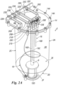
- FIG 1 it illustrates schematically an ink recirculating system 1 for an inkjet printer, comprising: a tank 2 for said ink, a connecting module 4, a printhead 5 and a module 7 for refilling the tank 2.
- the tank 2 comprises, as usual for the person skilled in the art, an outlet line 3A for the ink outlet from the tank 2 in which it is contained, which is connected through the connecting module 4:
- the tank 2 further comprises, as usual for the person skilled in the art, a second inlet line 8A which is connected through the connecting module 4:
- the ink outlet line 3A is connected to the line 6A for the ink inlet in the tank by a first connecting sub-module 4A of the connecting module 4, which comprises: a pump 11 for recirculating the ink, and preferably also a filtering device 18 and a valve member 19, comprising for example a hydraulic limiter, adapted to direct the ink back into the tank 2, through the inlet line 6A, and / or to direct a part thereof to the printhead 5, through a second connecting sub-module 4B, also of the usual type for the person skilled in the art, not described in detail below.
- a first connecting sub-module 4A of the connecting module 4 which comprises: a pump 11 for recirculating the ink, and preferably also a filtering device 18 and a valve member 19, comprising for example a hydraulic limiter, adapted to direct the ink back into the tank 2, through the inlet line 6A, and / or to direct a part thereof to the printhead 5, through a second connecting sub-module 4B, also of the
- the connecting module 4 also comprises further sub-modules 4C-4E, for the management of the connections of the ink recirculation from the printhead 5, for the management of the module 7 for refilling of the tank 2, and for the management of the power supply 8A, also these sub-modules, being of the conventional type for the person skilled in the art, will not be further described.
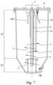
- the tank 2 of the recirculating system 1 comprises: a body 2A delimiting a cavity 2B ( Fig. 2A ) which has an upper 2C and a lower 2D ( Fig. 3 ) portion.
- the lower portion 2D comprises a convergent-shaped side wall 2E, which converges towards a bottom and closing wall 2F of the tank, and has a decreasing cross-section.
- the tank 2 comprises an outlet duct 9 for the ink outlet from the tank, provided inside the cavity 2B of the tank 2 and comprises an inlet opening 9A for the inlet of the ink to be moved out of the tank, provided above and near said bottom and closing wall 2F.
- the tank also comprises a first inlet duct 10 for the inlet in the tank 2 of the ink to be mixed, comprising an end portion 10A ( Fig. 5 ) having an opening 10B for the ink supply to the tank 2.
- the end portion 10A of the duct 10 is provided in the convergent-shaped part of the lower portion of the tank.
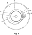
- the end portion 10A of the ink inlet duct 10 is substantially tangent to a portion T (dashed in Fig. 6 ) of a circular sector S of the convergent-shaped side wall 2E, of the lower portion 2D of the tank, so as to create: a substantially swirling flow F ( Fig. 7 ) in the ink supplied in the tank 2 from said inlet duct 10 or already present in the tank, and a mixing of the ink and / or the components thereof present in the tank.
- substantially tangent means that the end portion 10A can form with the portion T (dashed in figure 6 ) of the circular sector S of the side wall 2E, an angle between -10° (i.e. the end portion is slightly inclined towards the inside of the tank) and +10° (i.e. the end portion is slightly inclined towards the outside of the tank); however, it should be noted that the more this angle deviates from 0°, i.e. the less the end portion is tangent to the side wall 2E, the less will be the swirling flow F ( Fig. 7 ) created in the ink present in the tank, and the worse will be the mixing of the ink components in the tank.
- substantially tangent means that the end portion 10B can also form, with a horizontal plane passing through the portion T of the circular sector S of the side wall 2E, an angle between -10° (i.e. the end portion is inclined towards the bottom of the tank) and +10° (i.e. the end portion is inclined towards the upper part of the tank); however, it should be noted that the more this angle deviates from 0°, i.e.
- substantially swirling flow means a flow which creates a rotary movement of the ink around the longitudinal axis L of the tank at least in the lower portion 2D of the tank, but preferably also in the upper part 2C of the tank, and in which the tangential speed of said swirling flow decreases going from the bottom of the tank towards the top of the same.
- the swirling flow creates a vortex coaxial with the longitudinal axis of the tank at least in the lower portion 2D of the tank.
- the movement of the ink in the tank substantially affects the entire volume of the ink contained in the tank, primarily through a swirling flow, so as to have an extremely efficient ink mixing.
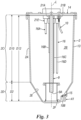
- the outlet opening 10B of the end portion 10A of the inlet duct 10 is provided at a distance D1 ( Fig. 3A ) from the bottom wall 2F of the tank between 80% and 20% of the overall height D2 of the converging part 2D of the tank 2, more preferably the distance D1 is between 60% and 30% of the height D2.
- D1 Fig. 3A
- the opening 9A of duct 9 is provided above and near the bottom and closing wall 2F; preferably, the distance D3 ( fig. 3 ) of the opening 9A from the bottom wall 2F is between 1% and 25% of the overall inner height D12 ( Fig. 3 ) of the tank, more preferably it is between 5% and 15% of this height D12, and even more preferably it is equal to about 10% of this height D12.
- the opening 9A is provided at a distance D3 from the inner face of the bottom wall 2F of the tank, less than 25 mm, more preferably less than 20 mm.
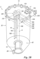
- the tank comprises at its bottom wall 2F a filtering element 12 which has a body, for example cylindrical in shape, having: an upper wall 12A ( Fig. 3A ), a lower wall 12B and a filtering side wall 12C which connects the two walls 12A and 12B to each other.
- the upper wall 12A has a through and axial opening adapted to be penetrated in a sealed manner by an end portion 9B of the duct 9 for the ink outlet, so that the opening 9A is axially housed inside the filtering element.
- the filtering element 12 rests against the bottom wall 2F of the tank and / or closes the tank at the bottom.
- the filtering element 12 is coaxial to a longitudinal axis L ( Fig. 3A ) of the tank.
- the lower wall 12B of the filtering element rests against the bottom wall 2F of the tank and is advantageously flush housed in a recessed seat 2H ( Fig. 3A ), suitably shaped and sized, obtained in the bottom wall 2F of the tank.
- the tank is substantially closed at the bottom by the filtering element 12, i.e. the inclined wall 2E of the tank, at the bottom, substantially reaches the filtering element 12, or it reaches a small distance D5 from the filtering element 12 (for example with D5 between 1% and 20% of the diameter D6 of the bottom wall 2F of the tank), so as to limit the portion in contact with the ink, of the bottom wall of the tank, to a limited size circular crown 2F' ( Fig. 3A ).
- the side wall 12C of the filtering element 12 connects the upper and lower walls 12A, B to each other, the wall 12C comprises a filtering net, for example a wire net, and for example with openings having dimensions between 50 and 300 microns and more preferably between 100 and 200 microns, which develops throughout the extension of the side wall or at least one part of said wall.
- the side wall 12C preferably comprises stiffening parts 12D ( Fig. 2 ) which connect the upper and lower walls 12A-B to each other.
- the upper wall 12A of the filtering element may also include the filtering net.
- the filtering element has:
- the filtering element has the function of protecting the components of the system to which the duct 9 sends the ink from particles of undesirable size which may be present in the ink.
- the filtering element helps in the formation of the swirling flow which is to be created in the tank, and in particular in its lower portion 2D, and in the space S ( Fig. 3A ) delimited by the converging wall 2E and the bottom wall 2F' of the tank and by the side wall 12C of the filtering element. Thanks to the presence of the filtering element 12 a sort of annular space S is created in the lower portion 2D of the tank, which channels the ink supplied into the tank, emitted by the opening 10B of the duct 10, in a swirling flow adapted to improve the ink mixing. Furthermore, the presence of the filtering element and its positioning coaxial to the tank prevents sediments from depositing in the middle of the bottom wall of the tank where, in the absence of the filtering element, the swirling flow of the ink has a lower speed.
- the swirling flow of the ink in the lower part of the tank also has a function of cleaning the filtering side wall 12C of the filtering element 12, preventing particles formation and accumulation on the side wall itself, so as to improve the efficiency and the life of the filtering element.
- the body 2A of the tank 2 has an axial symmetry and also the upper portion 2C thereof has a circular cross-section, preferably having an inner diameter D9 ( Fig. 3A ) which is constant and equal to the maximum inner diameter D21 of the lower portion 2D of the tank having the side wall 2E converging towards the bottom wall 2F of the tank.
- the height D2 of the lower portion is between 20% and 40% of the height D10 ( Fig. 3 ) of the upper portion 2C of the tank, more preferably it is equal to about 30% of D10.
- the converging wall 2E is inclined by an angle K ( Fig. 3A ) between 100° and 170°, more preferably between 120° and 150°.
- the converging wall 2E has a regular cross-section, coaxial to the longitudinal axis L of the tank and decreasing towards the bottom of the tank, preferably circular or elliptical or polygonal (for example octagonal) in shape.
- the tank has a ratio between the height / maximum diameter which is for example between 1: 1 and 2.5: 1 and more preferably it is equal to about 2: 1.
- the tank can for example have a volume between 0.21 and 61, more preferably between 0.51 and 21, and even more preferably equal to about 11.
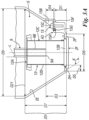
- the tank is sized and shaped in such a way as to provide a maximum level M for filling the tank which is provided at a distance D20 ( Fig. 4 ) from the bottom 2F of the tank between 40% and 70% of the inner overall height D16 of the tank, so that the tank provides a wall 2J of the tank not occupied by the ink.
- the duct 9 for the ink outlet from the tank is coaxial to the longitudinal axis L ( Fig. 3A ) of the tank, and is a straight duct.
- the inlet duct 10 is a flexible plastic tube, compatible with the ink.
- the inner diameter of the duct 10 is between 1.0 mm and 5.0 mm.
- the duct 10 has a substantially helical development, and forms an angle equal to about 360° or greater than 360° from its upper end portion to the lower one 10A.
- the helical development of the duct 10 also simplifies the operations for handling a lid 14 which closes the top of the tank, because the duct 10 will get to have a greater length than the overall height of the tank D16 ( Fig. 4 ); however, the technical problem could also be solved by using ducts having different characteristics, for example of the telescopic or extendable type.
- the duct 10 could also be shaped like an extensible tube having a non-helical but, for example, substantially vertical development.
- the tank also comprises means 15 for fixing the end portion 10A of the duct 10 in the desired position, tangent to the inclined wall 2E of the lower part 2D of the tank.
- the means 15 for example comprise a fixing element 15A ( Figs 3A and 3B ) and a shaped seat 15B adapted to at least partially house the end portion 10A, provided in the inclined wall 2E of the lower part 2D of the tank.
- the shaped seat 15B comprises, for example: a cavity 15G adapted to at least partially house the end portion 10A, which is blocked in said cavity 15G for example by a washer 15F of a head 15C of the fixing element 15.
- the means for fixing the end portion 10A of the duct 10 in the desired position, tangent to the inclined wall 2E of the lower part 2D of the tank, could also have a different shape from that described above and comprise for example a tubular element tangent to the inclined wall 2E and rigidly constrained to said wall 2E in the position in which said end portion 10A is to be positioned, in which to insert the end portion.
- the tank also comprises therein usual sensors 16 Fig. 2B ) adapted to detect the level of the ink in the tank; these sensors comprise for example three bar-type sensors 16A-C, one (16C) for detecting a low ink level (for example equal to 25% of the tank volume), one (16B) for detecting the optimal ink level, and one (16A) for detecting a high level (for example equal to 85% of the tank volume).
- the sensors 16 also include a sensor 16D adapted to supply a reference value.
- the tank also comprises a usual ventilation duct 18 ( Fig. 4 ) which is connected to the upper part of the tank and, in particular, to the tank lid 14, as discussed below.
- the tank also comprises, as usual for the person skilled in the art, a duct 17 for recirculating the ink coming from the printhead of a continuous inkjet printer (CIJ).
- CIJ continuous inkjet printer
- the tank has a portion 17D ( Fig. 4A ) extending inside the tank and comprises a small lower opening 17A for supplying the recirculated ink into the tank.
- a guide element 17B for example a sheet inclined towards the wall of the tank and towards the bottom of the tank, is provided below the opening 17A, which is adapted to guide the ink up to an inner side wall 2J of the upper portion 2C of the tank, at the upper edge thereof. Since the ink which is recirculated may contain a significant quantity of air in the form of bubbles or foam, the blade-shaped guide element 17B also has the function of separating the air from the returning ink.
- the free edge 17C of the sheet 17B of the guide element is provided at a distance D13 from the inner face of the wall 2J of the tank of one or more millimeters. Thanks to the guide element 17B, the ink which initially enters the tank vertically through the duct 17D is deflected laterally against the inner wall 2J of the tank, so as to create an ink film which flows along the inner wall 2J of the tank. In this way the recirculated ink flow which can have a high flow rate or a pulsating development is turned into a film that flows slowly towards the surface of the ink present in the tank.
- the tank 2 is sized in such a way as to be able to position the guide element 17B in the tank at a significant distance D14 ( fig.4 ) from the maximum level M for filling the tank with the ink, which allows the recirculated ink film to flow along a large surface of the inner wall 2J of the tank exposed to the air and which is not covered by the ink, so that the air bubbles and / or the foam present in the recirculated ink are eliminated and at the same time the recirculated ink comes into contact with the ink present in the tank smoothly avoiding splattering or splashing.
- D14 fig.4
- the tank optimal filling level is provided at a distance D20 ( Fig. 4 ) from the bottom 2F of the tank, this distance D20 between 40% and 70% of the tank overall inner height D16, so that the tank includes a wall portion 2J of the tank which is not occupied by the ink and along which the recirculated liquid can flow.
- This wall portion 2J has a height D15 ( fig. 4 ) which is between 30% and 60% of the overall height D16 of the tank, more preferably between 40% and 50% of the overall height D16 of the tank.
- the guide element 17B is positioned at a distance D14 from the tank optimal filling level M, and this distance D14 is between 30% and 60% of the overall height D16 of the tank, more preferably between 40% and 50% of the overall height D16 of the tank.
- the duct 17, as usual for the person skilled in the art, can be used to also supply into the tank the ink and / or the components thereof which do not come from the printhead, but for example from the module 7, adapted to feed the tank 2 with the ink and / or ink components.
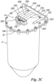
- the tank comprises a top lid 14 adapted to close the tank itself.
- the lid 14 comprises connecting means 14A, B for removably fixing it to the tank (2); for example screws 14A ( Fig. 2 ) adapted to fix it to the upper edge 2L ( Fig. 2C ) of the tank, in seats 14B provided at said edge of the tank.
- the duct 9 for the ink outlet from the tank 2, and the duct 10 for the ink and / or the components thereof inlet in the tank 2 are connected to the lid by means of dedicated connecting means 20A, 20B ( Fig. 2 ) in one piece and/or associated with the lid; preferably, also the ventilation duct 18 and / or the duct 17 for the recirculating ink inlet are connected to the lid by means of dedicated connecting means 20D, 20C in one piece and / or associated with the lid; even more preferably the level sensors 16 are also connected to the lid by means of dedicated connecting means 20E in one piece and / or associated with the lid.
- the connecting means 20A-D each comprise, for example: a first connecting element 21A-D that faces the inside of the tank, adapted to receive and sealingly connect one end of said ducts 9, 10, 17, 18 (only some of these first connecting elements can be seen in the Figures), an intermediate tubular element 22A-D adapted to connect the first connecting element 21A-D and, therefore, also the respective ducts 9, 10, 17, 18, to second connecting elements 23A-D provided outside the lid and the tank and adapted to connect the tank to the ducts 3A, 6A, 8A of the ink recirculating system that, as described above, are provided for the ink outlet from the tank 2, for the ink and / or the components thereof inlet into the tank and for the recirculated ink inlet into the tank, respectively.
- the connecting means 20E of the level sensors also comprises: a plurality of first elements 21E ( Fig. 4 ) which face the inside of the tank, and are adapted to receive and sealingly connect one end of the level sensors 16, an intermediate element 22E ( Fig. 4 ) for connecting the sensors 16 to a plurality of second connecting elements 23E provided outside the lid, for connecting the sensors to a control unit (not shown) of the printer.
- the assembly and / or maintenance of the tank are extremely simplified and speeded up.
- the tank 2 together with its lid 14 forms a single and compact module having all the connections necessary for its connection to the other modules of the ink recirculating system of the inkjet printer.
- the ink recirculating system 1 comprises a circuit C1 for recirculating and mixing the ink present in the tank ( Fig. 1 ) which allows the ink present in the tank 2 to be moved and mixed.
- this circuit C1 takes the ink from the tank through the duct 9 and through the pump 11, feeds it back into the tank 2, through the duct 10 of the tank, thus ensuring homogeneous characteristics of the ink present in tank 2.
- the pump 11 takes the ink from the tank, feeds it to the outlet line 3A, which is external and connected to the tank, and feeds it back into the tank 2, through the inlet line 6A, external and connected to the tank, and the duct 10 inside the tank. Downstream of the pump an ink filter 18 and a valve member 19 (for example comprising a hydraulic limiter) are also preferably included.
- this recirculation of the ink allows to obtain an efficient movement of the ink in the tank and its optimal mixing.
- the flow rate P of the ink generated by the pump 11 is between: 1m / s and 15m / s, more preferably it is between 3m / s and 7m / s, and even more preferably it is equal to about 5m / s; where said flow rate leaving the opening 10B is calculated by dividing the volume of the ink fed in the time unit (1 second) by the pump 11 to the duct 10 by the cross-section of the outlet opening 10B of said duct 10.
- the printer when the printer is switched off for a short time, for example during the night, it is usual to control the printer so that, for example every hour, an ink mixing cycle is performed in the tank 2.
- the printer when the printer is switched off for a long time (for example due to a breakdown, or for maintenance or when the plant is starting up) and if a pigmented ink is used, the pigments can accumulate on the bottom of the tank 2 forming a layer of sediments which must be dispersed back into the ink when the printer is reactivated, it is usual to check the printer so that a mixing of the ink is carried out in the tank, before feeding the ink to the printhead.
- a part of the ink flow taken by the pump 11, circulating in the circuit C1 described above, is directed, for example through the valve member 19, to the printhead 5, through a supply line 5D, 5A and the relative connecting module 4B. Only a part of the flow rate of the ink moved by the pump 11 is directed to the printhead, for example less than 20%, and preferably about 50, of the flow rate of the ink generated by the pump 11 is fed to the printhead 5.
- the ink and / or the components thereof are taken from the refill module 7 and through the supply line or lines 7A, 7B 8A and the connecting module 4D, are fed to the inlet duct 17 provided in the upper part of the tank 2.
- the invention relates to generic inkjet printers and not only to continuous inkjet printers.
- the tank could have a plurality of ink supply ducts 10, identical to the previously described duct 10 and having end portions 10A angularly spaced apart along the wall 2E and all tangent to said wall.
- the technical solutions and / or the conformation relating to the lid 14, and / or to the filtering element 12, and/or to the second inlet duct 17 can also be adopted individually, or in combination with each other, even in tanks adapted to contain known types of ink, and having different technical characteristics from those described so far.
- the invention also relates to an ink tank for an inkjet printer, comprising:
- the filtering element 12 comprises one or more of the following features:
Landscapes
- Ink Jet (AREA)
Claims (10)
- Système de recirculation d'encre pour imprimante à jet d'encre, comprenant :a) un réservoir (2) pour ladite encre, comprenant :- un corps (2A) délimitant une cavité (2B) et ayant une partie supérieure (2C) et une partie inférieure (2D), dans lequel :- la partie inférieure (2D) comprend une paroi latérale (2E) en forme de convergent, qui converge vers une paroi de fond et de fermeture (2F) du réservoir, et présente une section transversale décroissante ;- un conduit de sortie (9) pour permettre à l'encre de sortir du réservoir, prévu à l'intérieur de la cavité (2B) du réservoir (2) ;- dans lequel ledit conduit de sortie (9) est coaxial à un axe longitudinal (L) du réservoir ;
et comprend une ouverture d'entrée (9A) pour permettre de retirer l'entrée de l'encre du réservoir, prévue au-dessus et près desdites parois de fond et de fermeture (2F) ;- un premier conduit (10) pour permettre de faire entrer dans le réservoir (2) l'encre à mélanger, comprenant :- une partie terminale (10A) comportant une ouverture (10B) pour permettre d'alimenter le réservoir (2) en encre,- dans lequel ladite partie terminale (10A) du conduit (10) est prévue dans la partie en forme de convergent de la partie inférieure du réservoir ;- de préférence, un conduit de ventilation (18) ;- de préférence, au moins un capteur (16) adapté pour détecter le niveau d'encre dans le réservoir ;b) une pompe (11) en communication fluidique avec lesdits conduits de sortie (9) et d'entrée (10), permettant d'acheminer sous pression l'encre présente dans le réservoir depuis ledit conduit de sortie vers ledit conduit d'entrée ;
caractérisé en ce que :- la partie terminale (10A) du premier conduit d'entrée d'encre (10) est sensiblement tangente à une partie (T) d'un secteur circulaire (S) de la paroi latérale en forme de convergent (2E) , de la partie inférieure (2D) du réservoir, de manière à créer un flux sensiblement tourbillonnant (F) dans l'encre présente dans le réservoir (2) et un mélange de l'encre et/ou de ses composants présents dans le réservoir. - Système de recirculation d'encre selon la revendication 1, caractérisé en ce que l'ouverture (10B) de la partie terminale (10A) du conduit d'entrée (10) est prévue à une distance (D1) de la paroi de fond (2F) du réservoir comprise entre 80% et 20% de la hauteur totale (D2) de la partie convergente (2D) du réservoir (2), de préférence la distance (D1) est comprise entre 60% et 30% de la hauteur (D2),
et / ou en ce que l'ouverture (10B) de la partie terminale (10A) du conduit d'entrée (10) est prévue au-dessous ou à la même distance que l'ouverture (9A) du conduit de sortie (9) pour permettre à l'encre de sortir du réservoir, et / ou en ce que, de préférence, la distance (D3) de ladite ouverture (9A) du conduit de sortie (9) par rapport à la paroi de fond (2F) est comprise entre 1 % et 25 % de la hauteur intérieure totale (D12) du réservoir, de préférence elle est comprise entre 5 % et 15 % de cette hauteur (D12), et davantage de préférence elle est égale à environ 10 % de cette hauteur (D12). - Système de recirculation d'encre selon une ou plusieurs des revendications précédentes, caractérisé en ce que le réservoir (2) comprend à l'intérieur et sur sa paroi inférieure (2F) un élément filtrant (12) et en ce que ladite ouverture (9A) du conduit de sortie (9) est logée à l'intérieur dudit élément filtrant (12), de manière à protéger les composants du système auxquels le conduit (9) alimente l'encre, des particules de dimensions indésirables qui peuvent être présentes dans l'encre elle-même.
- Système de recirculation d'encre selon une ou plusieurs des revendications précédentes, caractérisé en ce que, dans des conditions normales de fonctionnement, le débit (P) de l'encre généré par la pompe (11) est compris entre : lm/s et 15m/s, de préférence il est compris entre 3m/s et 7m/s, et davantage de préférence il est égal à environ 5m/s ; où ledit débit sortant de l'ouverture (10B) est calculé en divisant le volume de l'encre envoyée dans l'unité de temps (1 seconde) par la pompe (11) vers le conduit (10) par la section transversale de l'ouverture de sortie (10B) dudit conduit (10).
- Système de recirculation d'encre selon la revendication 3, caractérisé en ce que l'élément filtrant (12) comprend une ou plusieurs des caractéristiques suivantes :- l'élément filtrant (12) dispose d'un corps ayant une section transversale sensiblement circulaire ;- et/ou l'élément filtrant (12) repose contre la paroi de fond (2F) du réservoir (2), et/ou il ferme le réservoir (2) au fond,- et/ou l'élément filtrant (12) est coaxial à un axe longitudinal (L) du réservoir ;- et/ou l'élément filtrant (12) disposant d'un corps, par exemple de forme cylindrique, comprend : une paroi supérieure (12A), une paroi inférieure (12B) et une paroi latérale,- dans lequel, de préférence, la paroi supérieure (12A) présente une ouverture traversante et axiale adaptée pour être pénétrée de manière étanche par une partie terminale (9B) du conduit (9) pour permettre à l'encre de sortir, de sorte que l'ouverture (9A) est logée de manière axiale à l'intérieur de l'élément filtrant ;- dans lequel, de préférence, la paroi inférieure (12B) de l'élément filtrant repose sur la paroi de fond (2F) du réservoir et est de préférence logée dans un siège encastré (2H), obtenu dans la paroi de fond (2F) du réservoir ;- et/ou le réservoir (2) est sensiblement fermé au fond par l'élément filtrant (12), et, de préférence, la paroi inclinée (2E) du réservoir, au fond, atteint sensiblement l'élément filtrant (12), ou atteint une faible distance (D5) de l'élément filtrant (12), de manière à limiter la partie en contact avec l'encre, de la paroi de fond du réservoir, à une couronne circulaire de taille limitée (2F') ;- et/ou l'élément filtrant (12) a une hauteur (D7) comprise entre 100% et 50% de la hauteur totale (D2) de la partie convergente (2D) du réservoir, et de préférence entre 100% et 80% de (D2), et un diamètre (D8) de sa paroi latérale (12C) compris entre 100% et 50% du diamètre (D6) de la paroi de fond (2F) du réservoir, de préférence entre 100% et 80% de (D6) de la paroi de fond (2F) du réservoir.
- Système de recirculation d'encre selon une ou plusieurs des revendications précédentes, caractérisé en ce que le réservoir (2) comprend une ou plusieurs des caractéristiques suivantes :- le corps (2A) du réservoir (2) présente une symétrie axiale et sa partie supérieure (2C) a une section transversale circulaire, avec un diamètre intérieur (D9) constant et égal au diamètre intérieur maximal (D10) de la partie inférieure (2D) du réservoir dont la paroi latérale (2E) converge vers la paroi de fond (2F) du réservoir ;et/ou la hauteur (D2) de la partie inférieure est comprise entre 20% et 40% de la hauteur (D10) de la partie supérieure (2C) du réservoir, de préférence elle est égale à environ 30% de (D10) ;et/ou la paroi convergente (2E) est inclinée d'un angle (K) compris entre 100° et 170°, de préférence entre 120° et 150° ;et/ou le réservoir a un rapport entre la hauteur maximale et le diamètre qui est compris entre 1 : 1 et 2,5 : 1 et de préférence est égal à environ 2: 1 ;et/ou le réservoir a un volume compris entre 0,21 et 61, de préférence entre 0,51 et 21, et davantage de préférence égal à environ 11 ;et/ou le réservoir est de taille et de forme telles qu'il fournit un niveau optimal (M) permettant de remplir le réservoir, à une distance (D20) du fond (2F) du réservoir comprise entre 40% et 70% de la hauteur intérieure totale (D16) du réservoir, de sorte que le réservoir présente une paroi (2J) du réservoir non occupée par l'encre, dont la hauteur (D15) est comprise entre 20% et 60% de la hauteur totale (D16) du réservoir, de préférence entre 30% et 40% de la hauteur totale (D16) du réservoir ;et/ou le conduit (9) destiné à la sortie de l'encre du réservoir est coaxial à l'axe longitudinal (L) du réservoir et est un conduit droit ;et/ou le conduit d'entrée (10) est un tube en plastique flexible, et/ou le conduit d'entrée (10) a un diamètre intérieur compris entre 1,0 mm et 5,0 mm ;et/ou le conduit d'entrée (10) a un tracé sensiblement hélicoïdal et forme un angle égal à environ 360° ou supérieur à 360° entre son extrémité supérieure et l'extrémité inférieure (10A) ; et/ou la paroi convergente (2E) a une section transversale régulière, coaxiale à l'axe longitudinal (L) du réservoir et décroissante vers le fond du réservoir, de préférence de forme circulaire, elliptique ou polygonale.
- Système de recirculation d'encre selon une ou plusieurs des revendications précédentes, caractérisé en ce que le réservoir (2) comprend des moyens (15) de fixation de la partie terminale (10A) du conduit d'entrée (10) dans la position souhaitée, tangente à la paroi inclinée (2E) de la partie inférieure (2D) du réservoir,- dans lequel, de préférence, les moyens de fixation (15) comprennent un élément de fixation (15A) et un siège profilé (15B) adapté pour loger au moins en partie ledit élément profilé (15A), prévu dans la paroi inclinée (2E) de la partie inférieure (2D) du réservoir et formant un renfoncement dans ladite paroi inclinée.
- Système de recirculation d'encre selon une ou plusieurs des revendications précédentes, caractérisé en ce que le réservoir (2) comprend :- Au moins un deuxième conduit d'entrée (17) pour permettre l'entrée dans le réservoir de : l'encre et/ou des composants de l'encre, en communication fluidique :- avec une tête d'impression d'imprimante à jet d'encre (5), pour acheminer l'encre non utilisée par ladite tête d'impression (5) dans le réservoir ;- et/ou avec un module de recharge (7), adapté pour fournir au réservoir (2) l'encre et / ou les composants de celle-ci consommés pendant l'impression ;et en ce que le deuxième conduit d'entrée (17) comprend une ou plusieurs des caractéristiques suivantes :- ledit deuxième conduit d'entrée (17) fournit une ouverture (17A) permettant d'évacuer le liquide recirculant dans ledit deuxième conduit (17) dans le réservoir, dans lequel ladite ouverture (17A) étant prévue dans la partie supérieure (2C) du réservoir et au-dessus d'un niveau optimal (M) de l'encre dans le réservoir,- et/ou le deuxième conduit d'entrée (17) fournit une ouverture (17A) permettant d'évacuer le liquide recirculant dans ledit deuxième conduit (17) dans le réservoir, et un élément de guidage (17B) , par exemple une feuille inclinée vers le fond du réservoir, adapté pour guider ledit liquide jusqu'à une paroi latérale intérieure (2J) de la partie supérieure (2C) du réservoir, dans lequel, de préférence, un bord libre (17C) dudit élément de guidage est prévu à une distance (D13) de la face intérieure de la paroi (2J) du réservoir comprise entre 1 mm et 5 mm, de manière à créer un film dudit liquide qui s'écoule le long de la paroi intérieure (2J) du réservoir ;- et / ou le deuxième conduit d'entrée (17) fournit une ouverture (17A) permettant d'évacuer le liquide recirculant dans ledit deuxième conduit (17) dans le réservoir, dans lequel ladite ouverture (17A), et en particulier l'élément de guidage (17B) de celle-ci, est prévue à une distance significative (D14) du niveau de remplissage optimal maximal (M) du réservoir, qui permet à un film du liquide introduit dans le réservoir de s'écouler du deuxième conduit (17) le long d'une large surface de la paroi intérieure (2J) du réservoir exposée à l'air et non recouverte par l'encre, dans laquelle, de préférence, le réservoir est conçu de manière à fournir une hauteur (D15) de la paroi (2J) du réservoir non occupée par l'encre et le long de laquelle le liquide peut s'écouler qui est comprise entre 20 % et 60 % de la hauteur totale (D16) du réservoir et, de préférence, entre 30 % et 40 % de la hauteur totale (D16) ; et dans lequel, par conséquent, ladite ouverture d'évacuation (17A) est également positionnée à une distance (D14) du niveau de remplissage optimal (M) du réservoir comprise entre 20% et 60% de la hauteur totale (D16) du réservoir, de préférence entre 30% et 40% de la hauteur totale (D16) du réservoir.
- Système de recirculation d'encre selon une ou plusieurs des revendications précédentes, caractérisé en ce que le réservoir (2) comprend un couvercle (14) adapté pour fermer le dessus du réservoir lui-même, en ce que ledit couvercle (14) comprend des moyens de connexion (14A) permettant de le fixer de manière amovible au réservoir (2) ;
et en ce que ledit couvercle (14) comprend des premiers moyens de connexion (20A) (20B) permettant de connecter au couvercle au moins le conduit (9) de sortie de l'encre du réservoir (2), et de préférence aussi au moins le premier conduit (10) d'entrée de l'encre dans le réservoir (2) ; et en ce que ledit couvercle comprend une ou plusieurs des caractéristiques suivantes :- le couvercle comprend d'autres moyens de connexion (20D) permettant également de connecter un conduit de ventilation (18) au couvercle ;- et/ou le couvercle comprend d'autres moyens de connexion (20C) permettant de connecter un deuxième conduit (17) pour permettre à l'encre et/ou ses composants d'entrer dans le couvercle ;- et/ou le couvercle comprend d'autres moyens de connexion (20E) permettant de connecter au moins un capteur (16) au couvercle afin de détecter le niveau (16) de l'encre dans le réservoir ;- et/ou au moins un desdits moyens de connexion (20A-E) et de préférence tous lesdits moyens de connexion (20A-E), sont au moins en partie fabriqués en une seule pièce et/ou associés au couvercle (14) ;- et/ou au moins un desdits moyens de connexion (20A-D) pour lesdits conduits (9), (10), (17), (18) et de préférence tous lesdits moyens de connexion (20A-D) comprennent chacun :- un premier élément de connexion (21A-D) orienté vers l'intérieur du réservoir et adapté pour recevoir et connecter de manière étanche une extrémité desdits conduits (9), (10), (17), (18) ;- au moins un élément tubulaire intermédiaire (22A-D) adapté pour connecter ledit premier élément de connexion (21A-D) et donc aussi les conduits respectifs (9), (10), (17), (18), à des deuxièmes éléments de connexion (23A-D) prévus à l'extérieur du couvercle et adaptés pour connecter le réservoir aux conduits (3A), (6A), (8A) du système de recirculation d'encre, prévus, par exemple, respectivement pour la sortie de l'encre du réservoir (2), pour l'encre et (7A) et ses composants (7B) alimentant le réservoir et pour l'alimentation du réservoir en encre recirculée ;- et/ou les moyens de connexion (20E) d'au moins un capteur (16) comprennent au moins un premier élément (21E) tourné vers l'intérieur du réservoir, adapté pour recevoir et connecter de manière étanche une extrémité du capteur de niveau (16), un élément intermédiaire (22E) pour connecter le capteur (16) à au moins un deuxième élément de connexion (23E) prévu à l'extérieur du couvercle. - Imprimante à jet d'encre comprenant un système de recirculation d'encre selon une ou plusieurs des revendications 1 à 9.
Applications Claiming Priority (1)
| Application Number | Priority Date | Filing Date | Title |
|---|---|---|---|
| IT102022000004577A IT202200004577A1 (it) | 2022-03-10 | 2022-03-10 | Un sistema di circolazione dell’inchiostro per una stampante a getto d'inchiostro |
Publications (3)
| Publication Number | Publication Date |
|---|---|
| EP4242001A1 EP4242001A1 (fr) | 2023-09-13 |
| EP4242001B1 true EP4242001B1 (fr) | 2024-08-14 |
| EP4242001C0 EP4242001C0 (fr) | 2024-08-14 |
Family
ID=81928186
Family Applications (1)
| Application Number | Title | Priority Date | Filing Date |
|---|---|---|---|
| EP23160212.9A Active EP4242001B1 (fr) | 2022-03-10 | 2023-03-06 | Système de recirculation d'encre pour imprimante à jet d'encre |
Country Status (4)
| Country | Link |
|---|---|
| US (1) | US20230286287A1 (fr) |
| EP (1) | EP4242001B1 (fr) |
| CN (1) | CN116728970A (fr) |
| IT (1) | IT202200004577A1 (fr) |
Family Cites Families (5)
| Publication number | Priority date | Publication date | Assignee | Title |
|---|---|---|---|---|
| US2413420A (en) * | 1940-02-26 | 1946-12-31 | Thermo Plastics Corp | Method and apparatus for dispersing or drying fluent material in high velocity elastic fluid jets |
| US6551518B2 (en) * | 1999-07-12 | 2003-04-22 | Joseph Gargas | Combined ozonation and electrolytic chlorination water purification method |
| US8371684B2 (en) | 2011-01-31 | 2013-02-12 | Videojet Technologies Inc. | Ink mixing system |
| FR3036650A1 (fr) * | 2015-05-29 | 2016-12-02 | Dover Europe Sarl | Procede et dispositif de gestion de la qualite d'encre d'une imprimante a jet d'encre |
| US12128009B1 (en) * | 2020-04-25 | 2024-10-29 | Cirkul, Inc. | Systems and methods for bottle apparatuses, container assemblies, and dispensing apparatuses |
-
2022
- 2022-03-10 IT IT102022000004577A patent/IT202200004577A1/it unknown
-
2023
- 2023-03-06 EP EP23160212.9A patent/EP4242001B1/fr active Active
- 2023-03-08 CN CN202310256045.4A patent/CN116728970A/zh active Pending
- 2023-03-10 US US18/120,009 patent/US20230286287A1/en active Pending
Also Published As
| Publication number | Publication date |
|---|---|
| CN116728970A (zh) | 2023-09-12 |
| EP4242001C0 (fr) | 2024-08-14 |
| EP4242001A1 (fr) | 2023-09-13 |
| US20230286287A1 (en) | 2023-09-14 |
| IT202200004577A1 (it) | 2023-09-10 |
Similar Documents
| Publication | Publication Date | Title |
|---|---|---|
| JP6099306B2 (ja) | 記録媒体に印刷するためのインクプリンタ | |
| EP2489516B1 (fr) | Système de circulation de liquide et imprimante à jet d'encre | |
| JP6078301B2 (ja) | ダンパー装置およびインクジェットプリンター | |
| US10226940B2 (en) | Printer fluid circulation system including an air isolation chamber and a printer fluid pressure control valve | |
| JP2023029648A (ja) | 液体吐出ヘッド、液体吐出装置及び液体の供給方法 | |
| EP2313278B1 (fr) | Dispositif d'impression à jet d'encre | |
| CN112839822B (zh) | 用于容器中液体混合物的循环设备 | |
| EP2098372A1 (fr) | Système d'alimentation en encre sans pompe pour imprimante à jet d'encre dotée d'un système de recyclage d'encre | |
| EP4242001B1 (fr) | Système de recirculation d'encre pour imprimante à jet d'encre | |
| CN102529398A (zh) | 用于微流体应用的消耗品供给部件、流体贮存器及再循环系统 | |
| KR20190079823A (ko) | 잉크젯 프린팅 장치 | |
| JP5837855B2 (ja) | インクジェットプリンタ | |
| EP3694721B1 (fr) | Dispersion de pigment dans une imprimante à jet d'encre | |
| CN215397743U (zh) | 喷墨打印头供墨系统 | |
| JP2016141071A (ja) | インク供給装置、インクジェット画像形成装置およびインクジェット画像形成方法 | |
| JP2018165014A (ja) | インクジェット記録装置 | |
| CN113276565A (zh) | 喷墨打印头供墨系统 | |
| CN217396029U (zh) | 一种喷墨打印机用自平衡供墨系统 | |
| CN217553491U (zh) | 喷墨打印头供墨系统 | |
| US10363753B2 (en) | Liquid ejecting apparatuses | |
| JP2018001507A (ja) | インクジェット記録装置 | |
| JP2017114091A (ja) | インクジェット記録装置 | |
| CN221437524U (zh) | 喷墨打印机的喷头墨水循环装置 | |
| JPWO2022118699A5 (fr) | ||
| CN223099973U (zh) | 供墨系统、喷墨3d打印装置及3d打印机 |
Legal Events
| Date | Code | Title | Description |
|---|---|---|---|
| PUAI | Public reference made under article 153(3) epc to a published international application that has entered the european phase |
Free format text: ORIGINAL CODE: 0009012 |
|
| STAA | Information on the status of an ep patent application or granted ep patent |
Free format text: STATUS: THE APPLICATION HAS BEEN PUBLISHED |
|
| AK | Designated contracting states |
Kind code of ref document: A1 Designated state(s): AL AT BE BG CH CY CZ DE DK EE ES FI FR GB GR HR HU IE IS IT LI LT LU LV MC ME MK MT NL NO PL PT RO RS SE SI SK SM TR |
|
| STAA | Information on the status of an ep patent application or granted ep patent |
Free format text: STATUS: REQUEST FOR EXAMINATION WAS MADE |
|
| GRAP | Despatch of communication of intention to grant a patent |
Free format text: ORIGINAL CODE: EPIDOSNIGR1 |
|
| STAA | Information on the status of an ep patent application or granted ep patent |
Free format text: STATUS: GRANT OF PATENT IS INTENDED |
|
| 17P | Request for examination filed |
Effective date: 20240214 |
|
| RBV | Designated contracting states (corrected) |
Designated state(s): AL AT BE BG CH CY CZ DE DK EE ES FI FR GB GR HR HU IE IS IT LI LT LU LV MC ME MK MT NL NO PL PT RO RS SE SI SK SM TR |
|
| RIC1 | Information provided on ipc code assigned before grant |
Ipc: B41J 2/20 20060101ALI20240304BHEP Ipc: B41J 2/18 20060101ALI20240304BHEP Ipc: B41J 2/175 20060101AFI20240304BHEP |
|
| INTG | Intention to grant announced |
Effective date: 20240318 |
|
| GRAS | Grant fee paid |
Free format text: ORIGINAL CODE: EPIDOSNIGR3 |
|
| GRAA | (expected) grant |
Free format text: ORIGINAL CODE: 0009210 |
|
| STAA | Information on the status of an ep patent application or granted ep patent |
Free format text: STATUS: THE PATENT HAS BEEN GRANTED |
|
| AK | Designated contracting states |
Kind code of ref document: B1 Designated state(s): AL AT BE BG CH CY CZ DE DK EE ES FI FR GB GR HR HU IE IS IT LI LT LU LV MC ME MK MT NL NO PL PT RO RS SE SI SK SM TR |
|
| REG | Reference to a national code |
Ref country code: GB Ref legal event code: FG4D |
|
| REG | Reference to a national code |
Ref country code: CH Ref legal event code: EP |
|
| REG | Reference to a national code |
Ref country code: DE Ref legal event code: R096 Ref document number: 602023000369 Country of ref document: DE |
|
| REG | Reference to a national code |
Ref country code: IE Ref legal event code: FG4D |
|
| U01 | Request for unitary effect filed |
Effective date: 20240902 |
|
| U07 | Unitary effect registered |
Designated state(s): AT BE BG DE DK EE FI FR IT LT LU LV MT NL PT RO SE SI Effective date: 20240912 |
|
| PG25 | Lapsed in a contracting state [announced via postgrant information from national office to epo] |
Ref country code: NO Free format text: LAPSE BECAUSE OF FAILURE TO SUBMIT A TRANSLATION OF THE DESCRIPTION OR TO PAY THE FEE WITHIN THE PRESCRIBED TIME-LIMIT Effective date: 20241114 |
|
| PG25 | Lapsed in a contracting state [announced via postgrant information from national office to epo] |
Ref country code: GR Free format text: LAPSE BECAUSE OF FAILURE TO SUBMIT A TRANSLATION OF THE DESCRIPTION OR TO PAY THE FEE WITHIN THE PRESCRIBED TIME-LIMIT Effective date: 20241115 Ref country code: PL Free format text: LAPSE BECAUSE OF FAILURE TO SUBMIT A TRANSLATION OF THE DESCRIPTION OR TO PAY THE FEE WITHIN THE PRESCRIBED TIME-LIMIT Effective date: 20240814 |
|
| PG25 | Lapsed in a contracting state [announced via postgrant information from national office to epo] |
Ref country code: IS Free format text: LAPSE BECAUSE OF FAILURE TO SUBMIT A TRANSLATION OF THE DESCRIPTION OR TO PAY THE FEE WITHIN THE PRESCRIBED TIME-LIMIT Effective date: 20241214 |
|
| PG25 | Lapsed in a contracting state [announced via postgrant information from national office to epo] |
Ref country code: HR Free format text: LAPSE BECAUSE OF FAILURE TO SUBMIT A TRANSLATION OF THE DESCRIPTION OR TO PAY THE FEE WITHIN THE PRESCRIBED TIME-LIMIT Effective date: 20240814 |
|
| PG25 | Lapsed in a contracting state [announced via postgrant information from national office to epo] |
Ref country code: ES Free format text: LAPSE BECAUSE OF FAILURE TO SUBMIT A TRANSLATION OF THE DESCRIPTION OR TO PAY THE FEE WITHIN THE PRESCRIBED TIME-LIMIT Effective date: 20240814 Ref country code: RS Free format text: LAPSE BECAUSE OF FAILURE TO SUBMIT A TRANSLATION OF THE DESCRIPTION OR TO PAY THE FEE WITHIN THE PRESCRIBED TIME-LIMIT Effective date: 20241114 |
|
| PG25 | Lapsed in a contracting state [announced via postgrant information from national office to epo] |
Ref country code: RS Free format text: LAPSE BECAUSE OF FAILURE TO SUBMIT A TRANSLATION OF THE DESCRIPTION OR TO PAY THE FEE WITHIN THE PRESCRIBED TIME-LIMIT Effective date: 20241114 Ref country code: PL Free format text: LAPSE BECAUSE OF FAILURE TO SUBMIT A TRANSLATION OF THE DESCRIPTION OR TO PAY THE FEE WITHIN THE PRESCRIBED TIME-LIMIT Effective date: 20240814 Ref country code: NO Free format text: LAPSE BECAUSE OF FAILURE TO SUBMIT A TRANSLATION OF THE DESCRIPTION OR TO PAY THE FEE WITHIN THE PRESCRIBED TIME-LIMIT Effective date: 20241114 Ref country code: IS Free format text: LAPSE BECAUSE OF FAILURE TO SUBMIT A TRANSLATION OF THE DESCRIPTION OR TO PAY THE FEE WITHIN THE PRESCRIBED TIME-LIMIT Effective date: 20241214 Ref country code: HR Free format text: LAPSE BECAUSE OF FAILURE TO SUBMIT A TRANSLATION OF THE DESCRIPTION OR TO PAY THE FEE WITHIN THE PRESCRIBED TIME-LIMIT Effective date: 20240814 Ref country code: GR Free format text: LAPSE BECAUSE OF FAILURE TO SUBMIT A TRANSLATION OF THE DESCRIPTION OR TO PAY THE FEE WITHIN THE PRESCRIBED TIME-LIMIT Effective date: 20241115 Ref country code: ES Free format text: LAPSE BECAUSE OF FAILURE TO SUBMIT A TRANSLATION OF THE DESCRIPTION OR TO PAY THE FEE WITHIN THE PRESCRIBED TIME-LIMIT Effective date: 20240814 |
|
| U20 | Renewal fee for the european patent with unitary effect paid |
Year of fee payment: 3 Effective date: 20250114 |
|
| PG25 | Lapsed in a contracting state [announced via postgrant information from national office to epo] |
Ref country code: SM Free format text: LAPSE BECAUSE OF FAILURE TO SUBMIT A TRANSLATION OF THE DESCRIPTION OR TO PAY THE FEE WITHIN THE PRESCRIBED TIME-LIMIT Effective date: 20240814 |
|
| PG25 | Lapsed in a contracting state [announced via postgrant information from national office to epo] |
Ref country code: CZ Free format text: LAPSE BECAUSE OF FAILURE TO SUBMIT A TRANSLATION OF THE DESCRIPTION OR TO PAY THE FEE WITHIN THE PRESCRIBED TIME-LIMIT Effective date: 20240814 |
|
| PG25 | Lapsed in a contracting state [announced via postgrant information from national office to epo] |
Ref country code: SK Free format text: LAPSE BECAUSE OF FAILURE TO SUBMIT A TRANSLATION OF THE DESCRIPTION OR TO PAY THE FEE WITHIN THE PRESCRIBED TIME-LIMIT Effective date: 20240814 |
|
| PLBE | No opposition filed within time limit |
Free format text: ORIGINAL CODE: 0009261 |
|
| STAA | Information on the status of an ep patent application or granted ep patent |
Free format text: STATUS: NO OPPOSITION FILED WITHIN TIME LIMIT |
|
| 26N | No opposition filed |
Effective date: 20250515 |
|
| PG25 | Lapsed in a contracting state [announced via postgrant information from national office to epo] |
Ref country code: MC Free format text: LAPSE BECAUSE OF FAILURE TO SUBMIT A TRANSLATION OF THE DESCRIPTION OR TO PAY THE FEE WITHIN THE PRESCRIBED TIME-LIMIT Effective date: 20240814 |