EP4241967A1 - Shimming welded interface(s) between thermoplastic components - Google Patents
Shimming welded interface(s) between thermoplastic components Download PDFInfo
- Publication number
- EP4241967A1 EP4241967A1 EP23160618.7A EP23160618A EP4241967A1 EP 4241967 A1 EP4241967 A1 EP 4241967A1 EP 23160618 A EP23160618 A EP 23160618A EP 4241967 A1 EP4241967 A1 EP 4241967A1
- Authority
- EP
- European Patent Office
- Prior art keywords
- shim
- support member
- skin
- interface
- component
- Prior art date
- Legal status (The legal status is an assumption and is not a legal conclusion. Google has not performed a legal analysis and makes no representation as to the accuracy of the status listed.)
- Pending
Links
Images





Classifications
-
- B—PERFORMING OPERATIONS; TRANSPORTING
- B29—WORKING OF PLASTICS; WORKING OF SUBSTANCES IN A PLASTIC STATE IN GENERAL
- B29C—SHAPING OR JOINING OF PLASTICS; SHAPING OF MATERIAL IN A PLASTIC STATE, NOT OTHERWISE PROVIDED FOR; AFTER-TREATMENT OF THE SHAPED PRODUCTS, e.g. REPAIRING
- B29C66/00—General aspects of processes or apparatus for joining preformed parts
- B29C66/90—Measuring or controlling the joining process
- B29C66/95—Measuring or controlling the joining process by measuring or controlling specific variables not covered by groups B29C66/91 - B29C66/94
-
- B—PERFORMING OPERATIONS; TRANSPORTING
- B29—WORKING OF PLASTICS; WORKING OF SUBSTANCES IN A PLASTIC STATE IN GENERAL
- B29C—SHAPING OR JOINING OF PLASTICS; SHAPING OF MATERIAL IN A PLASTIC STATE, NOT OTHERWISE PROVIDED FOR; AFTER-TREATMENT OF THE SHAPED PRODUCTS, e.g. REPAIRING
- B29C65/00—Joining or sealing of preformed parts, e.g. welding of plastics materials; Apparatus therefor
- B29C65/02—Joining or sealing of preformed parts, e.g. welding of plastics materials; Apparatus therefor by heating, with or without pressure
-
- B—PERFORMING OPERATIONS; TRANSPORTING
- B29—WORKING OF PLASTICS; WORKING OF SUBSTANCES IN A PLASTIC STATE IN GENERAL
- B29C—SHAPING OR JOINING OF PLASTICS; SHAPING OF MATERIAL IN A PLASTIC STATE, NOT OTHERWISE PROVIDED FOR; AFTER-TREATMENT OF THE SHAPED PRODUCTS, e.g. REPAIRING
- B29C65/00—Joining or sealing of preformed parts, e.g. welding of plastics materials; Apparatus therefor
- B29C65/48—Joining or sealing of preformed parts, e.g. welding of plastics materials; Apparatus therefor using adhesives, i.e. using supplementary joining material; solvent bonding
- B29C65/4805—Joining or sealing of preformed parts, e.g. welding of plastics materials; Apparatus therefor using adhesives, i.e. using supplementary joining material; solvent bonding characterised by the type of adhesives
- B29C65/481—Non-reactive adhesives, e.g. physically hardening adhesives
- B29C65/4815—Hot melt adhesives, e.g. thermoplastic adhesives
-
- B—PERFORMING OPERATIONS; TRANSPORTING
- B29—WORKING OF PLASTICS; WORKING OF SUBSTANCES IN A PLASTIC STATE IN GENERAL
- B29C—SHAPING OR JOINING OF PLASTICS; SHAPING OF MATERIAL IN A PLASTIC STATE, NOT OTHERWISE PROVIDED FOR; AFTER-TREATMENT OF THE SHAPED PRODUCTS, e.g. REPAIRING
- B29C65/00—Joining or sealing of preformed parts, e.g. welding of plastics materials; Apparatus therefor
- B29C65/48—Joining or sealing of preformed parts, e.g. welding of plastics materials; Apparatus therefor using adhesives, i.e. using supplementary joining material; solvent bonding
- B29C65/50—Joining or sealing of preformed parts, e.g. welding of plastics materials; Apparatus therefor using adhesives, i.e. using supplementary joining material; solvent bonding using adhesive tape, e.g. thermoplastic tape; using threads or the like
- B29C65/5007—Joining or sealing of preformed parts, e.g. welding of plastics materials; Apparatus therefor using adhesives, i.e. using supplementary joining material; solvent bonding using adhesive tape, e.g. thermoplastic tape; using threads or the like characterised by the structure of said adhesive tape, threads or the like
- B29C65/5014—Joining or sealing of preformed parts, e.g. welding of plastics materials; Apparatus therefor using adhesives, i.e. using supplementary joining material; solvent bonding using adhesive tape, e.g. thermoplastic tape; using threads or the like characterised by the structure of said adhesive tape, threads or the like being fibre-reinforced
-
- B—PERFORMING OPERATIONS; TRANSPORTING
- B29—WORKING OF PLASTICS; WORKING OF SUBSTANCES IN A PLASTIC STATE IN GENERAL
- B29C—SHAPING OR JOINING OF PLASTICS; SHAPING OF MATERIAL IN A PLASTIC STATE, NOT OTHERWISE PROVIDED FOR; AFTER-TREATMENT OF THE SHAPED PRODUCTS, e.g. REPAIRING
- B29C65/00—Joining or sealing of preformed parts, e.g. welding of plastics materials; Apparatus therefor
- B29C65/48—Joining or sealing of preformed parts, e.g. welding of plastics materials; Apparatus therefor using adhesives, i.e. using supplementary joining material; solvent bonding
- B29C65/50—Joining or sealing of preformed parts, e.g. welding of plastics materials; Apparatus therefor using adhesives, i.e. using supplementary joining material; solvent bonding using adhesive tape, e.g. thermoplastic tape; using threads or the like
- B29C65/5057—Joining or sealing of preformed parts, e.g. welding of plastics materials; Apparatus therefor using adhesives, i.e. using supplementary joining material; solvent bonding using adhesive tape, e.g. thermoplastic tape; using threads or the like positioned between the surfaces to be joined
-
- B—PERFORMING OPERATIONS; TRANSPORTING
- B29—WORKING OF PLASTICS; WORKING OF SUBSTANCES IN A PLASTIC STATE IN GENERAL
- B29C—SHAPING OR JOINING OF PLASTICS; SHAPING OF MATERIAL IN A PLASTIC STATE, NOT OTHERWISE PROVIDED FOR; AFTER-TREATMENT OF THE SHAPED PRODUCTS, e.g. REPAIRING
- B29C66/00—General aspects of processes or apparatus for joining preformed parts
- B29C66/01—General aspects dealing with the joint area or with the area to be joined
- B29C66/05—Particular design of joint configurations
- B29C66/10—Particular design of joint configurations particular design of the joint cross-sections
- B29C66/11—Joint cross-sections comprising a single joint-segment, i.e. one of the parts to be joined comprising a single joint-segment in the joint cross-section
- B29C66/112—Single lapped joints
-
- B—PERFORMING OPERATIONS; TRANSPORTING
- B29—WORKING OF PLASTICS; WORKING OF SUBSTANCES IN A PLASTIC STATE IN GENERAL
- B29C—SHAPING OR JOINING OF PLASTICS; SHAPING OF MATERIAL IN A PLASTIC STATE, NOT OTHERWISE PROVIDED FOR; AFTER-TREATMENT OF THE SHAPED PRODUCTS, e.g. REPAIRING
- B29C66/00—General aspects of processes or apparatus for joining preformed parts
- B29C66/01—General aspects dealing with the joint area or with the area to be joined
- B29C66/05—Particular design of joint configurations
- B29C66/10—Particular design of joint configurations particular design of the joint cross-sections
- B29C66/11—Joint cross-sections comprising a single joint-segment, i.e. one of the parts to be joined comprising a single joint-segment in the joint cross-section
- B29C66/112—Single lapped joints
- B29C66/1122—Single lap to lap joints, i.e. overlap joints
-
- B—PERFORMING OPERATIONS; TRANSPORTING
- B29—WORKING OF PLASTICS; WORKING OF SUBSTANCES IN A PLASTIC STATE IN GENERAL
- B29C—SHAPING OR JOINING OF PLASTICS; SHAPING OF MATERIAL IN A PLASTIC STATE, NOT OTHERWISE PROVIDED FOR; AFTER-TREATMENT OF THE SHAPED PRODUCTS, e.g. REPAIRING
- B29C66/00—General aspects of processes or apparatus for joining preformed parts
- B29C66/01—General aspects dealing with the joint area or with the area to be joined
- B29C66/05—Particular design of joint configurations
- B29C66/10—Particular design of joint configurations particular design of the joint cross-sections
- B29C66/12—Joint cross-sections combining only two joint-segments; Tongue and groove joints; Tenon and mortise joints; Stepped joint cross-sections
- B29C66/122—Joint cross-sections combining only two joint-segments, i.e. one of the parts to be joined comprising only two joint-segments in the joint cross-section
- B29C66/1222—Joint cross-sections combining only two joint-segments, i.e. one of the parts to be joined comprising only two joint-segments in the joint cross-section comprising at least a lapped joint-segment
- B29C66/12221—Joint cross-sections combining only two joint-segments, i.e. one of the parts to be joined comprising only two joint-segments in the joint cross-section comprising at least a lapped joint-segment the two joint-segments being lapped
-
- B—PERFORMING OPERATIONS; TRANSPORTING
- B29—WORKING OF PLASTICS; WORKING OF SUBSTANCES IN A PLASTIC STATE IN GENERAL
- B29C—SHAPING OR JOINING OF PLASTICS; SHAPING OF MATERIAL IN A PLASTIC STATE, NOT OTHERWISE PROVIDED FOR; AFTER-TREATMENT OF THE SHAPED PRODUCTS, e.g. REPAIRING
- B29C66/00—General aspects of processes or apparatus for joining preformed parts
- B29C66/01—General aspects dealing with the joint area or with the area to be joined
- B29C66/05—Particular design of joint configurations
- B29C66/10—Particular design of joint configurations particular design of the joint cross-sections
- B29C66/13—Single flanged joints; Fin-type joints; Single hem joints; Edge joints; Interpenetrating fingered joints; Other specific particular designs of joint cross-sections not provided for in groups B29C66/11 - B29C66/12
- B29C66/131—Single flanged joints, i.e. one of the parts to be joined being rigid and flanged in the joint area
-
- B—PERFORMING OPERATIONS; TRANSPORTING
- B29—WORKING OF PLASTICS; WORKING OF SUBSTANCES IN A PLASTIC STATE IN GENERAL
- B29C—SHAPING OR JOINING OF PLASTICS; SHAPING OF MATERIAL IN A PLASTIC STATE, NOT OTHERWISE PROVIDED FOR; AFTER-TREATMENT OF THE SHAPED PRODUCTS, e.g. REPAIRING
- B29C66/00—General aspects of processes or apparatus for joining preformed parts
- B29C66/40—General aspects of joining substantially flat articles, e.g. plates, sheets or web-like materials; Making flat seams in tubular or hollow articles; Joining single elements to substantially flat surfaces
- B29C66/47—Joining single elements to sheets, plates or other substantially flat surfaces
- B29C66/474—Joining single elements to sheets, plates or other substantially flat surfaces said single elements being substantially non-flat
-
- B—PERFORMING OPERATIONS; TRANSPORTING
- B29—WORKING OF PLASTICS; WORKING OF SUBSTANCES IN A PLASTIC STATE IN GENERAL
- B29C—SHAPING OR JOINING OF PLASTICS; SHAPING OF MATERIAL IN A PLASTIC STATE, NOT OTHERWISE PROVIDED FOR; AFTER-TREATMENT OF THE SHAPED PRODUCTS, e.g. REPAIRING
- B29C66/00—General aspects of processes or apparatus for joining preformed parts
- B29C66/50—General aspects of joining tubular articles; General aspects of joining long products, i.e. bars or profiled elements; General aspects of joining single elements to tubular articles, hollow articles or bars; General aspects of joining several hollow-preforms to form hollow or tubular articles
- B29C66/51—Joining tubular articles, profiled elements or bars; Joining single elements to tubular articles, hollow articles or bars; Joining several hollow-preforms to form hollow or tubular articles
- B29C66/53—Joining single elements to tubular articles, hollow articles or bars
- B29C66/532—Joining single elements to the wall of tubular articles, hollow articles or bars
- B29C66/5324—Joining single elements to the wall of tubular articles, hollow articles or bars said single elements being substantially annular, i.e. of finite length
- B29C66/53245—Joining single elements to the wall of tubular articles, hollow articles or bars said single elements being substantially annular, i.e. of finite length said articles being hollow
-
- B—PERFORMING OPERATIONS; TRANSPORTING
- B29—WORKING OF PLASTICS; WORKING OF SUBSTANCES IN A PLASTIC STATE IN GENERAL
- B29C—SHAPING OR JOINING OF PLASTICS; SHAPING OF MATERIAL IN A PLASTIC STATE, NOT OTHERWISE PROVIDED FOR; AFTER-TREATMENT OF THE SHAPED PRODUCTS, e.g. REPAIRING
- B29C66/00—General aspects of processes or apparatus for joining preformed parts
- B29C66/70—General aspects of processes or apparatus for joining preformed parts characterised by the composition, physical properties or the structure of the material of the parts to be joined; Joining with non-plastics material
- B29C66/72—General aspects of processes or apparatus for joining preformed parts characterised by the composition, physical properties or the structure of the material of the parts to be joined; Joining with non-plastics material characterised by the structure of the material of the parts to be joined
- B29C66/721—Fibre-reinforced materials
-
- B—PERFORMING OPERATIONS; TRANSPORTING
- B29—WORKING OF PLASTICS; WORKING OF SUBSTANCES IN A PLASTIC STATE IN GENERAL
- B29C—SHAPING OR JOINING OF PLASTICS; SHAPING OF MATERIAL IN A PLASTIC STATE, NOT OTHERWISE PROVIDED FOR; AFTER-TREATMENT OF THE SHAPED PRODUCTS, e.g. REPAIRING
- B29C65/00—Joining or sealing of preformed parts, e.g. welding of plastics materials; Apparatus therefor
- B29C65/02—Joining or sealing of preformed parts, e.g. welding of plastics materials; Apparatus therefor by heating, with or without pressure
- B29C65/08—Joining or sealing of preformed parts, e.g. welding of plastics materials; Apparatus therefor by heating, with or without pressure using ultrasonic vibrations
-
- B—PERFORMING OPERATIONS; TRANSPORTING
- B29—WORKING OF PLASTICS; WORKING OF SUBSTANCES IN A PLASTIC STATE IN GENERAL
- B29C—SHAPING OR JOINING OF PLASTICS; SHAPING OF MATERIAL IN A PLASTIC STATE, NOT OTHERWISE PROVIDED FOR; AFTER-TREATMENT OF THE SHAPED PRODUCTS, e.g. REPAIRING
- B29C65/00—Joining or sealing of preformed parts, e.g. welding of plastics materials; Apparatus therefor
- B29C65/02—Joining or sealing of preformed parts, e.g. welding of plastics materials; Apparatus therefor by heating, with or without pressure
- B29C65/34—Joining or sealing of preformed parts, e.g. welding of plastics materials; Apparatus therefor by heating, with or without pressure using heated elements which remain in the joint, e.g. "verlorenes Schweisselement"
- B29C65/36—Joining or sealing of preformed parts, e.g. welding of plastics materials; Apparatus therefor by heating, with or without pressure using heated elements which remain in the joint, e.g. "verlorenes Schweisselement" heated by induction
-
- B—PERFORMING OPERATIONS; TRANSPORTING
- B29—WORKING OF PLASTICS; WORKING OF SUBSTANCES IN A PLASTIC STATE IN GENERAL
- B29C—SHAPING OR JOINING OF PLASTICS; SHAPING OF MATERIAL IN A PLASTIC STATE, NOT OTHERWISE PROVIDED FOR; AFTER-TREATMENT OF THE SHAPED PRODUCTS, e.g. REPAIRING
- B29C66/00—General aspects of processes or apparatus for joining preformed parts
- B29C66/70—General aspects of processes or apparatus for joining preformed parts characterised by the composition, physical properties or the structure of the material of the parts to be joined; Joining with non-plastics material
- B29C66/72—General aspects of processes or apparatus for joining preformed parts characterised by the composition, physical properties or the structure of the material of the parts to be joined; Joining with non-plastics material characterised by the structure of the material of the parts to be joined
- B29C66/721—Fibre-reinforced materials
- B29C66/7212—Fibre-reinforced materials characterised by the composition of the fibres
-
- B—PERFORMING OPERATIONS; TRANSPORTING
- B29—WORKING OF PLASTICS; WORKING OF SUBSTANCES IN A PLASTIC STATE IN GENERAL
- B29L—INDEXING SCHEME ASSOCIATED WITH SUBCLASS B29C, RELATING TO PARTICULAR ARTICLES
- B29L2031/00—Other particular articles
- B29L2031/30—Vehicles, e.g. ships or aircraft, or body parts thereof
- B29L2031/3076—Aircrafts
-
- Y—GENERAL TAGGING OF NEW TECHNOLOGICAL DEVELOPMENTS; GENERAL TAGGING OF CROSS-SECTIONAL TECHNOLOGIES SPANNING OVER SEVERAL SECTIONS OF THE IPC; TECHNICAL SUBJECTS COVERED BY FORMER USPC CROSS-REFERENCE ART COLLECTIONS [XRACs] AND DIGESTS
- Y02—TECHNOLOGIES OR APPLICATIONS FOR MITIGATION OR ADAPTATION AGAINST CLIMATE CHANGE
- Y02T—CLIMATE CHANGE MITIGATION TECHNOLOGIES RELATED TO TRANSPORTATION
- Y02T50/00—Aeronautics or air transport
- Y02T50/40—Weight reduction
Definitions
- This invention relates generally to forming thermoplastic structures and, more particularly, to welding thermoplastic components together.
- thermoplastic materials are increasingly being used in various aerospace applications.
- Various methods are known in the art for welding thermoplastic material components together. While these known methods have various advantages, there is still room in the art for improvement. There is a need in the art therefore for improved methods for forming thermoplastic structures with multiple components welded together.
- a method for joining thermoplastic components.
- a skin is provided that is configured from or otherwise includes a skin fiber-reinforced thermoplastic composite.
- a support member is provided that is configured from or otherwise includes a support member fiber-reinforced thermoplastic composite.
- a shim is arranged at an interface between the skin and the support member.
- the shim is configured from or otherwise includes a shim fiber-reinforced thermoplastic composite.
- the support member is welded to the skin through the shim at the interface.
- the support member may thus be welded to the skin via a single weld that extends through the thickness of the shim or via a first weld between the support member and the shim and a second, separate, weld between the shim and the skin.
- thermoplastic components for an aircraft.
- a first component is arranged with a second component.
- the first component is configured from or otherwise includes a first fiber-reinforced thermoplastic composite.
- the second component is configured from or otherwise includes a second fiber-reinforced thermoplastic composite.
- a gap is between the first component and the second component at an interface between the first component and the second component.
- a parameter of the gap is determined.
- One of a plurality of shims is selected based on the parameter to provide a selected shim.
- the selected shim is configured from or otherwise includes a shim fiber-reinforced thermoplastic composite.
- the selected shim is arranged between the first component and the second component at the interface.
- the first component is welded to the second component through the selected shim at the interface.
- the welding includes vibration welding, ultrasonic welding and/or induction welding.
- the first component may thus be welded to the second component via a single weld that extends through the thickness of the shim or via a first weld between the first component and the shim and a second, separate, weld between the shim and the second component.
- thermoplastic component for an aircraft.
- a first component is arranged with a second component.
- the first component is configured from or otherwise includes a first fiber-reinforced thermoplastic composite.
- the second component is configured from or otherwise includes a second fiber-reinforced thermoplastic composite.
- a gap is between the first component and the second component at an interface between the first component and the second component.
- a parameter of the gap is determined.
- a shim is formed based on the parameter.
- the shim is configured from or otherwise includes a shim fiber-reinforced thermoplastic composite.
- the shim is arranged between the first component and the second component at the interface. The first component is welded to the second component through the shim at the interface.
- the welding is configured from or otherwise includes vibration welding, ultrasonic welding and/or induction welding.
- the first component may thus be welded to the second component via a single weld that extends through the thickness of the shim or via a first weld between the first component and the shim and a second, separate, weld between the shim and the second component.
- the selected shim may have a first configuration.
- a second one of the shims may have a second configuration that is different than the first configuration.
- the shims may be formed prior to the determining of the parameter of the gap.
- the support member may be welded to the skin through the shim along a length of the interface.
- the support member may be welded directly to the skin along a first portion of the interface.
- the support member may be welded to the skin through the shim along a second portion of the interface.
- the shim may extend vertically between the skin and the support member.
- the shim may have a constant vertical thickness as the shim extends longitudinally and/or laterally along the interface.
- the shim may extend vertically between the skin and the support member.
- the shim may have a vertically thickness that changes as the shim extends longitudinally and/or laterally along the interface.
- the method may also include: providing a plurality of shims; and selecting one of the shims based on a configuration of a gap between the support member and the skin at the interface without the shim.
- the selected one of the shims is the shim that is to be arranged at the interface between the skin and the support member.
- the one of the shims may be selected based on a size of the gap.
- the one of the shims may be selected based on a geometry of the gap.
- the method may also include: determining a parameter of a gap between the support member and the skin at the interface without the shim; and manufacturing the shim based on the parameter.
- the method may also include welding the support member to the skin at a second interface that is discrete from the interface.
- the support member may be concurrently welded to the skin at the interface and the second interface.
- the support member may be directedly welded to the skin at the second interface.
- the method may also include: arranging a second shim at the second interface between the skin and the support member, where the second shim may be configured from or otherwise include second shim fiber-reinforced thermoplastic composite; and welding the support member to the skin through the second shim at the second interface.
- the shim fiber-reinforced thermoplastic composite may be configured as or otherwise include carbon fibers within a thermoplastic matrix.
- the welding may include ultrasonic welding, vibration welding and/or induction welding the support member to the skin through the shim at the interface.
- the support member may be configured as or otherwise include a support surface.
- the shim may be configured as or otherwise include a shim surface that is abutted against the support surface.
- a surface area of the shim surface may be equal to between ninety percent (90%) and one-hundred and ten percent (110%) of a surface area of the support surface.
- the method may also include forming an aircraft component.
- the aircraft component may include the skin, the support member and the shim.
- the skin may form an exterior surface of the aircraft component.
- the invention may include any one or more of the individual features disclosed above and/or below alone or in any combination thereof.
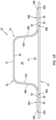
- FIGS. 1A and 1B illustrate a portion of a fiber-reinforced thermoplastic structure 20 for an aircraft.
- This structure 20 may be configured as part of a propulsion system for the aircraft.
- the structure 20, for example, may be configured as a component of a nacelle.
- the nacelle component include, but not limited to, a fan cowl, an outer barrel, an inner barrel, an inlet lip skin and a translating sleeve.
- the structure 20 may alternatively be configured as a component of a fuselage or a wing of the aircraft.
- the structure 20 may still alternatively be configured as a component arranged within the aircraft fuselage; e.g., a component within a cabin of the aircraft.
- the present disclosure is not limited to the foregoing exemplary aircraft structures. Furthermore, it is contemplated the structure 20 of the present disclosure may also be configured for non-aircraft applications. However, for ease of description, the structure 20 may be referred to and/or described below as an aircraft structure such as the nacelle structure.
- the aircraft structure 20 of FIGS. 1A and 1B includes a plurality of components including an exterior skin 22 and a support member 24; e.g., a structural support.
- the support member 24 may be configured as a stiffener, a pedestal, a structural core and/or any other member which stiffens, holds, locates and/or otherwise supports the aircraft structure 20 and/or its exterior skin 22.
- the stiffener include, but are not limited to, a rib, a stringer, a longeron, a beam and a truss.
- the support member 24 may be referred to and/or described below as a stiffener; e.g., a hat shaped stiffener.
- the support member 24 of FIG. 1A extends longitudinally along a longitudinal centerline 26 of the support member 24.
- the support member 24 extends laterally between and to a first side 28A of the support member 24 and a second side 28B of the support member 24.
- the support member 24 extends vertically between and to an exterior side 30 of the support member 24 and an interior side 32 of the support member 24.
- the support member 24 of FIG. 1A includes a channeled base 34 and one or more mounts 36A and 36B (generally referred to as "36"); e.g., flanges.
- the channeled base 34 extends longitudinally along the longitudinal centerline 26.
- the channeled base 34 extends laterally between and to a first side 38A of the channeled base 34 and a second side 38B of the channeled base 34.
- the channeled base 34 extends vertically between and to (or about) the support interior side 32 and the support exterior side 30.
- the channeled base 34 is configured with a U-shaped cross-sectional geometry when viewed, for example, in a reference plane perpendicular to the longitudinal centerline 26.
- This configuration provides the channeled base 34 with a channel 40 that extends longitudinally in (e.g., through) the support member 24 and its channeled base 34.
- the channel 40 extends laterally in (e.g., within) the support member 24 and its channeled base 34 between opposing sidewalls 42A and 42B (generally referred to as "42") of the channeled base 34.
- the channel 40 projects vertically into the support member 24 and its channeled base 34 from the support exterior side 30 to an endwall 44 of the channeled base 34.
- Each of the mounts 36 is connected to (e.g., formed integral with) the channeled base 34. Each of the mounts 36 is disposed at (e.g., on, adjacent or proximate) the support exterior side 30. Each of the mounts 36A, 36B projects laterally out from a respective one of the base sidewalls 42A, 42B to a distal end 46A, 46B of that mount 36. These mounts 36A, 36B project may laterally out from the channeled base 34 and its base sidewalls 42A, 42B in opposite directions and away the channel 40; however, the present disclosure is not limited to such an exemplary mount arrangement. Each of the mounts 36 is welded to the exterior skin 22 at / along a respective interface 48A, 48B (generally referred to as "48") between the support member 24 and its mount 36A, 36B and the exterior skin 22.
- 48 respective interface 48A, 48B
- the aircraft structure components 22 and 24 may be constructed from one or more layers of component material, where the component materials of the aircraft structure components 22 and 24 may be common component materials (e.g., the same component materials) or unique component materials (e.g., different component materials).
- Each component material may be a fiber-reinforced thermoplastic composite.
- Fiber-reinforcement 50 for example, may be embedded within a thermoplastic material 52; e.g., a thermoplastic matrix.
- the fiber-reinforcement 50 examples include, but are not limited to, metal fibers (e.g., aluminum fibers, brass fibers, and stainless steel fibers), carbon fibers including graphite fibers (e.g., polyacrylonitrile (PAN)-based carbon fibers, rayon-based carbon fibers, lignin-based carbon fibers, and pitch-based carbon fibers), insulating fibers (e.g., glass fibers), organic fibers (e.g., aramid fibers, polyparaphenylene benzoxazole (PBO) fibers, polyphenylene sulfide fibers, polyester fibers, acrylic fibers, nylon fibers, and polyethylene fibers), and inorganic fibers (e.g., silicon carbide fibers and silicon nitride fibers). Some or all of these fibers may be continuous fibers. Some or all of the fibers may also or alternatively be chopped fibers.
- the present disclosure is not limited to the foregoing exemplary fiber-reinforcement materials or fibers
- thermoplastic material 52 examples include, but are not limited to, a semicrystalline thermoplastic resin and an amorphous thermoplastic resin.
- semicrystalline thermoplastic resin examples include, but are not limited to, polyester, polyolefin, polyoxymethylene (POM), polyamide (PA), polyarylene sulfide, polyketone (PK), polyetherketone (PEK), polyether ether ketone (PEEK), polyether ketone ketone (PEKK), polyvinylidene fluoride (PVDF), polytetrafluoroethylene (PTFE), polyaryletherketone (PAEK), polyether nitrile (PEN), fluororesin, and liquid crystal polymer (LCP).
- polyester examples include, but are not limited to, polyethylene terephthalate (PET), polybutylene terephthalate (PBT), polytrimethylene terphthalate (PTT), polyethylene naphthalate (PEN), and liquid crystal polyester.
- polyolefin examples include, but are not limited to, polyethylene (PE), polypropylene (PP), and polybutylene.
- polyarylene sulfide includes, but is not limited to, polyphenylene sulfide (PPS).
- fluororesin includes, but is not limited to, polytetrafluoroethylene.
- thermoplastic resin examples include, but are not limited to, polystyrene, polycarbonate (PC), polymethyl methacrylate (PMMA), polyvinyl chloride (PVC), polyphenylene ether (PPE), polyimide (PI), polyamide imide (PAI), polyetherimide (PEI), polysulfone (PSU), polyether sulfone (PES), and polyarylate (PAR).
- PC polycarbonate
- PMMA polymethyl methacrylate
- PVC polyvinyl chloride
- PPE polyphenylene ether
- PI polyimide
- PAI polyamide imide
- PEI polyetherimide
- PSU polysulfone
- PES polyether sulfone
- PAR polyarylate
- the aircraft structure components 22 and 24 are formed using one or more manufacturing processes. Examples of these manufacturing processes include, but are not limited to, stamp forming, compression molding, injection molding, over-molding and laminating. Referring to FIGS. 3A-C , due to (e.g., dimensional, geometric, etc.) deviations in the aircraft structure components 22 and 24 within tolerances for the respective manufacturing process(es), one or more inter-component gaps 54 (one visible in FIGS. 3A-C ) may be defined when the actual support member 24 (versus the design space support member) is arranged with (e.g., abutted against, engaged with, etc.) the actual exterior skin 22 (versus the design space exterior skin). The inter-component gap 54 of FIGS.
- the inter-component gap 54 of FIGS. 3A-C extends vertically between and to an interior surface 56 of the exterior skin 22 and a support surface 58 (e.g., flange surface) of the support member 24 and a respective one of its mounts 36 (e.g., flanges), where these component surfaces 56 and 58 are typically designed to contact one another (e.g., lay flush against one another) absent deviations.
- a support surface 58 e.g., flange surface
- mounts 36 e.g., flanges
- the inter-component gap 54 of FIG. 3A extends (e.g., partially or completely) laterally across the interface 48 between the exterior skin 22 and the respective mount 29.
- the inter-component gap 54 of FIG. 3A for example, extends along an entire lateral width 60 of the respective mount 36 and its support surface 58.
- at least a portion of the support member 24 and its support surface 58 may contact and/or lay flush against the exterior skin 22 and its interior surface 56.
- the inter-component gap 54 of FIGS. 3B and 3C extends (e.g., partially or completely) longitudinally along the interface 48 between the exterior skin 22 and the respective mount 36.
- the inter-component gap 54 of FIG. 3B for example, extends along an entire longitudinal length 62 of the respective mount 36 and its support surface 58.
- the inter-component gap 54 of FIG. 3C by contrast, extends along a portion of the longitudinal length 62 of the respective mount 36 and its support surface 58.
- one or more portions 64A and 64B of the respective mount 36 and its support surface 58 may vertically contact (e.g., lay flush against) the exterior skin 22 and its interior surface 56.
- one or more inter-component shims 66 may be provided to plug and/or bridge one or more of the inter-component gaps 54.
- the inter-component shim 66 of FIGS. 4A-C is disposed vertically between the support member 24 and the exterior skin 22. More particularly, the inter-component shim 66 of FIGS. 4A-C extends vertically between and to the interior surface 56 and the support surface 58. A skin side surface 68 of the inter-component shim 66 may thereby vertically contact (e.g., lay flush against) the interior surface 56.
- a support side surface 70 of the inter-component shim 66 may vertically contact (e.g., lay flush against) the support surface 58.
- the inter-component shim 66 may be configured with exactly or substantially the same configuration (e.g., size, geometry, etc.) of a respective inter-component gap 54 (see also FIGS. 3A-C ) such that the inter-component shim 66 of FIGS. 4A-C completely or substantially fills and/or bridges the inter-component gap 54.
- the inter-component shim 66 of FIG. 4A extends (e.g., partially or completely) laterally across the interface 48 between the exterior skin 22 and the respective mount 36.
- the inter-component shim 66 of FIG. 4A extends along the entire lateral width 60 of the respective mount 36 and its support surface 58.
- a lateral width 72 of the inter-component shim 66 may be slightly larger than or slightly smaller than the lateral width 60 of the respective mount 36 and its support surface 58; e.g., see dashed lines.
- the inter-component shim 66 of FIGS. 4B and 4C extends (e.g., partially or completely) longitudinally along the interface 48 between the exterior skin 22 and the respective mount 36.
- the inter-component shim 66 of FIG. 4B extends along the entire longitudinal length 62 of the respective mount 36 and its support surface 58.
- a longitudinal length 74 of the inter-component shim 66 may be slightly larger than or slightly smaller than the longitudinal length 62 of the respective mount 36 and its support surface 58; e.g., see dashed lines.
- a surface area of the support surface 58 may be equal to exactly, or between ninety percent (90%) and one-hundred and ten percent (110%) (e.g., between 95% and 105%) of, of a surface area of the shim support side surface 70.
- the inter-component shim 66 of FIG. 4C extends along a portion of the longitudinal length 62 of the respective mount 36 and its support surface 58. With such an arrangement, one or more portions of the respective mount 36 and its support surface 58 adjacent the inter-component shim 66 may vertically contact (e.g., lay flush against) the exterior skin 22 and its interior surface 56.
- the surface area of the support surface 58 may thereby be equal to less than the surface area of the shim support side surface 70.
- the surface area of the support surface 58 may be equal to between (a) five percent (5%) and twenty-five percent (25%), (b) twenty-five percent (25%) and fifty percent (50%), (c) fifty percent (50%) and seventy-five percent (75%), or (d) seventy-five percent (75%) and ninety-five percent (95%) of the surface area of the shim support side surface 70.
- the support member 24 and its respective mount 36 may be welded to the exterior skin 22 along an entirety of, a substantial portion of, or various predetermined locations along a longitudinal length of the interface 48.
- an inter-component gap 54 remains unfilled, only a portion (if any) of the support member 24 may be welded to the exterior skin 22 along the interface 48.
- provision of the inter-component shim 66 may facilitate arranging the support member 24 with the exterior skin 22 without deforming (e.g., bending, deflecting, twisting, etc.) either of these aircraft structure components 22 and 24 to fit flush against one another. Such deformation may impart undesirable internal stressed within the aircraft structure 20 and/or lead to deformation (e.g., warping or otherwise misshaping) of the aircraft structure 20.
- a vertical thickness 76 of the inter-component shim 66 may remain constant laterally across the inter-component shim 66.
- the vertical thickness 76 of the inter-component shim 66 may (e.g., continuously or intermittently) vary laterally across the inter-component shim 66.
- the vertical thickness 76 of the inter-component shim 66 of FIG. 5B decreases as the inter-component shim 66 extends laterally from a first side 78A (e.g., a left side in FIG.
- the inter-component shim 66 may vertically taper along the lateral width 72 thereof.
- the vertical thickness 76 of the inter-component shim 66 may remain constant longitudinally along the inter-component shim 66. In other embodiments, referring to FIGS. 6B and 6C , the vertical thickness 76 of the inter-component shim 66 may (e.g., continuously or intermittently) vary longitudinally across the inter-component shim 66. The vertical thickness 76 of the inter-component shim 66 of FIG. 6B , for example, decreases as the inter-component shim 66 extends longitudinally from a first end 78A (e.g., a left end in FIG.
- the inter-component shim 66 may vertically taper along a longitudinal length 74 thereof.
- the vertical thickness 76 of the inter-component shim 66 may increase and then decrease as the inter-component shim 66 extends longitudinally from the shim first end 78A to the shim second end 78B; e.g., the inter-component shim 66 may vertically flare out and then taper along the longitudinal length 74 thereof.
- one or more or all of the mounts 36 may be arranged with at least one of the inter-component shims 66.
- the inter-component shim 66 may be arranged with a first one of the mounts (e.g., 36A), whereas a second one of the mounts (e.g., 36B) may be configured without an inter-component shim.
- the first mount 36A of FIG. 7A is welded to the exterior skin 22 at the first interface 48A through the inter-component shim 66 according to any one or more of the arrangements described above; e.g., see FIGS. 4A-6C .
- the second mount 36B of FIG. 7A is welded to the exterior skin 22 directly; e.g., not through an inter-component shim.
- a respective inter-component shim 66A, 66B (generally referred to as "66") may be arranged with each of the mounts 36A, 36B. More particularly, each mount 36 of FIG. 7B is welded to the exterior skin 22 through a respective one of the inter-component shims 66 according to any one or more of the arrangements described above; e.g., see FIGS. 4A-6C .
- each inter-component shim 66 may be constructed from one or more layers of a material that is the same as or different than the support member material and/or the exterior skin material.
- Each inter-component shim 66 may be constructed from a fiber-reinforced thermoplastic composite.
- Fiber-reinforcement 50 for example, may be embedded within a thermoplastic material 52; e.g., a thermoplastic matrix.
- a thermoplastic material 52 e.g., a thermoplastic matrix.
- the fiber-reinforcement 50 and the thermoplastic material 52 are described above; however, the present disclosure is not limited to such exemplary materials.
- FIG. 9 is a flow diagram of a method 900 for manufacturing a structure such as, but not limited to, the aircraft structure 20 described above.
- this method 900 is described below utilizing one inter-component shim 66 for one of the mounts 36.
- that mount 36 may be arranged with multiple inter-component shim 66 and/or another mount 36 may also be arranged with one or more inter-component shims 66.
- a first component of the aircraft structure 20 is provided.
- the exterior skin 22, for example, may be stamp formed, compression molded, injection molded, over-molded and laminated and/or otherwise manufactured as the first structure component.
- a second component of the aircraft structure 20 is provided.
- the support member 24, for example, may be stamp formed, compression molded, injection molded, over-molded and laminated and/or otherwise manufactured as the second structure component.
- the first structure component is arranged with the second component structure.
- the support member 24, for example, may be disposed with the exterior skin 22 for a test fit. More particularly, referring to FIGS. 3A-C , the support member 24 is abutted against the exterior skin 22 such that the support surface(s) 58 at least partially contact the interior surface 56. Due to deviations in the aircraft structure components 22 and 24 within tolerances for the respective manufacturing process(es) of steps 902 and/or 904, at least one inter-component gap 54 is formed between the support member 24 and the exterior skin 22. This inter-component gap 54 extends between a first of the mounts (e.g., 36A) (e.g., a first mount) and the exterior skin 22; of course, in other embodiments, additional inter-component gaps 54 may be present.
- a first of the mounts e.g., 36A
- additional inter-component gaps 54 may be present.
- one or more parameters of the inter-component gap 54 are determined.
- One or more dimensions (e.g., vertical height, lateral width and/or longitudinal length) of the inter-component gap 54 may be measured and/or otherwise determined.
- a geometry (e.g., shape, contour, etc.) of the inter-component gap 54 may also or alternatively be scanned, modeled and/or otherwise determined.
- an inter-component shim 66 is provided based on the one or more determined parameters.
- the inter-component shim 66 may be stamp formed, compression molded, injection molded, over-molded and laminated and/or otherwise manufactured according to the dimension(s) and/or geometry determined in the step 908.
- the inter-component shim 66 may thereby be provided as a made-to-fit (e.g., an exact fit) shim that substantially or completely fills and/or bridges the inter-component gap 54.
- the inter-component shim 66 may be selected from a plurality of different (e.g., pre-made) available inter-component shims 66. For example, referring to FIG.
- a plurality of inter-component shims 66 with different sizes and/or geometries may be manufactured.
- one of these different (e.g., pre-made) inter-component shims 66 may be selected that most closely matches the size and/or the geometry of the inter-component gap 54.
- This selected inter-component shim 66 may then be used in the method 900 as is (e.g., without further modification), or modified (e.g., machined) to even more closely match the size and/or the geometry of the inter-component gap 54.
- the inter-component shim 66 is arranged with the first structure component and the second component structure.
- the inter-component shim 66 of FIGS. 4A-C for example, is arranged at the interface 48 between the first mount 36A and the exterior skin 22. More particularly, the inter-component shim 66 of FIGS. 4A-C is disposed vertically between the first mount 36A and the exterior skin 22 so as to partially or completely fill and/or bridge the inter-component gap 54 as described above.
- the second structure component is welded to the first structure component.
- the support member 24 of FIG. 7A for example, is welded to the exterior skin 22 at / along its interfaces 48.
- the first mount 36A more particularly, is welded to the exterior skin 22 at / along the first interface 48A through the inter-component shim 66.
- the first mount 36A for example, is welded to at least (or only) the inter-component shim 66, and the exterior skin 22 is welded to at least (or only) the inter-component shim 66 at / along the second interface 48B.
- the second mount 36B may be welded (e.g., directly) to the exterior skin 22.
- the welding at / along the first interface 48A and at / along the second interface 48B may be performed concurrently (e.g., simultaneously), or separately.
- the structure elements 22, 24 and 66 may be welded together using ultrasonic welding, vibration welding, induction welding and/or any other suitable (e.g., thermoplastic) welding process.
Landscapes
- Engineering & Computer Science (AREA)
- Mechanical Engineering (AREA)
- Lining Or Joining Of Plastics Or The Like (AREA)
Abstract
Description
- This invention relates generally to forming thermoplastic structures and, more particularly, to welding thermoplastic components together.
- Thermoplastic materials are increasingly being used in various aerospace applications. Various methods are known in the art for welding thermoplastic material components together. While these known methods have various advantages, there is still room in the art for improvement. There is a need in the art therefore for improved methods for forming thermoplastic structures with multiple components welded together.
- According to an aspect of the invention, a method is provided for joining thermoplastic components. During this method, a skin is provided that is configured from or otherwise includes a skin fiber-reinforced thermoplastic composite. A support member is provided that is configured from or otherwise includes a support member fiber-reinforced thermoplastic composite. A shim is arranged at an interface between the skin and the support member. The shim is configured from or otherwise includes a shim fiber-reinforced thermoplastic composite. The support member is welded to the skin through the shim at the interface. The support member may thus be welded to the skin via a single weld that extends through the thickness of the shim or via a first weld between the support member and the shim and a second, separate, weld between the shim and the skin.
- According to another aspect of the invention, another method is provided for joining thermoplastic components for an aircraft. During this method, a first component is arranged with a second component. The first component is configured from or otherwise includes a first fiber-reinforced thermoplastic composite. The second component is configured from or otherwise includes a second fiber-reinforced thermoplastic composite. A gap is between the first component and the second component at an interface between the first component and the second component. A parameter of the gap is determined. One of a plurality of shims is selected based on the parameter to provide a selected shim. The selected shim is configured from or otherwise includes a shim fiber-reinforced thermoplastic composite. The selected shim is arranged between the first component and the second component at the interface. The first component is welded to the second component through the selected shim at the interface. The welding includes vibration welding, ultrasonic welding and/or induction welding. The first component may thus be welded to the second component via a single weld that extends through the thickness of the shim or via a first weld between the first component and the shim and a second, separate, weld between the shim and the second component.
- According to still another aspect of the invention, another method is provided for joining thermoplastic component for an aircraft. During this method, a first component is arranged with a second component. The first component is configured from or otherwise includes a first fiber-reinforced thermoplastic composite. The second component is configured from or otherwise includes a second fiber-reinforced thermoplastic composite. A gap is between the first component and the second component at an interface between the first component and the second component. A parameter of the gap is determined. A shim is formed based on the parameter. The shim is configured from or otherwise includes a shim fiber-reinforced thermoplastic composite. The shim is arranged between the first component and the second component at the interface. The first component is welded to the second component through the shim at the interface. The welding is configured from or otherwise includes vibration welding, ultrasonic welding and/or induction welding. The first component may thus be welded to the second component via a single weld that extends through the thickness of the shim or via a first weld between the first component and the shim and a second, separate, weld between the shim and the second component.
- The selected shim may have a first configuration. A second one of the shims may have a second configuration that is different than the first configuration. The shims may be formed prior to the determining of the parameter of the gap.
- The support member may be welded to the skin through the shim along a length of the interface.
- The support member may be welded directly to the skin along a first portion of the interface. The support member may be welded to the skin through the shim along a second portion of the interface.
- The shim may extend vertically between the skin and the support member. The shim may have a constant vertical thickness as the shim extends longitudinally and/or laterally along the interface.
- The shim may extend vertically between the skin and the support member. The shim may have a vertically thickness that changes as the shim extends longitudinally and/or laterally along the interface.
- The method may also include: providing a plurality of shims; and selecting one of the shims based on a configuration of a gap between the support member and the skin at the interface without the shim. The selected one of the shims is the shim that is to be arranged at the interface between the skin and the support member.
- The one of the shims may be selected based on a size of the gap.
- The one of the shims may be selected based on a geometry of the gap.
- The method may also include: determining a parameter of a gap between the support member and the skin at the interface without the shim; and manufacturing the shim based on the parameter.
- The method may also include welding the support member to the skin at a second interface that is discrete from the interface.
- The support member may be concurrently welded to the skin at the interface and the second interface.
- The support member may be directedly welded to the skin at the second interface.
- The method may also include: arranging a second shim at the second interface between the skin and the support member, where the second shim may be configured from or otherwise include second shim fiber-reinforced thermoplastic composite; and welding the support member to the skin through the second shim at the second interface.
- The shim fiber-reinforced thermoplastic composite may be configured as or otherwise include carbon fibers within a thermoplastic matrix.
- The welding may include ultrasonic welding, vibration welding and/or induction welding the support member to the skin through the shim at the interface.
- The support member may be configured as or otherwise include a support surface. The shim may be configured as or otherwise include a shim surface that is abutted against the support surface. A surface area of the shim surface may be equal to between ninety percent (90%) and one-hundred and ten percent (110%) of a surface area of the support surface.
- The method may also include forming an aircraft component. The aircraft component may include the skin, the support member and the shim. The skin may form an exterior surface of the aircraft component.
- The invention, and/or any aspects of the invention, may include any one or more of the individual features disclosed above and/or below alone or in any combination thereof.
- The foregoing features and the operation of the invention will become more apparent in light of the following description and the accompanying drawings.
-
-
FIG. 1A is a perspective illustration of a portion of a fiber-reinforced thermoplastic structure. -
FIG. 1B is an illustration of an end of a portion of the fiber-reinforced thermoplastic structure. -
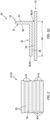
FIG. 2 is a partial sectional illustration of a structure component with a multi-layer configuration. -
FIG. 3A is a lateral sectional illustration of a portion of the fiber-reinforced thermoplastic structure at an inter-component gap. -
FIGS. 3B and 3C are longitudinal sectional illustrations of portions of the fiber-reinforced thermoplastic structure at the inter-component gap with various configurations. -
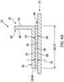
FIG. 4A is a lateral sectional illustration of a portion of the fiber-reinforced thermoplastic structure at an inter-component shim. -
FIGS. 4B and 4C are longitudinal sectional illustrations of portions of the fiber-reinforced thermoplastic structure at the inter-component shim with various configurations. -
FIGS. 5A and 5B are lateral sectional illustrations of the inter-component shim with various vertical heights along its width. -
FIGS. 6A-C are longitudinal sectional illustration of the inter-component shim with various vertical heights along its length. -
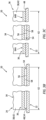
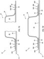
FIG. 7A is a sectional illustration of a portion of the fiber-reinforced thermoplastic structure configured with a single inter-component shim. -
FIG. 7B is a sectional illustration of a portion of the fiber-reinforced thermoplastic structure configured with multiple inter-component shims. -
FIGS. 8A and 8B are partial sectional illustrations of the inter-component shim with various constructions. -
FIG. 9 is a flow diagram of a method for manufacturing a structure. -
FIG. 10 is a schematic illustration of multiple inter-component shims with various different configurations. -
FIGS. 1A and1B illustrate a portion of a fiber-reinforcedthermoplastic structure 20 for an aircraft. Thisstructure 20 may be configured as part of a propulsion system for the aircraft. Thestructure 20, for example, may be configured as a component of a nacelle. Examples of the nacelle component include, but not limited to, a fan cowl, an outer barrel, an inner barrel, an inlet lip skin and a translating sleeve. Thestructure 20 may alternatively be configured as a component of a fuselage or a wing of the aircraft. Thestructure 20 may still alternatively be configured as a component arranged within the aircraft fuselage; e.g., a component within a cabin of the aircraft. The present disclosure, however, is not limited to the foregoing exemplary aircraft structures. Furthermore, it is contemplated thestructure 20 of the present disclosure may also be configured for non-aircraft applications. However, for ease of description, thestructure 20 may be referred to and/or described below as an aircraft structure such as the nacelle structure. - The
aircraft structure 20 ofFIGS. 1A and1B includes a plurality of components including anexterior skin 22 and asupport member 24; e.g., a structural support. Thesupport member 24 may be configured as a stiffener, a pedestal, a structural core and/or any other member which stiffens, holds, locates and/or otherwise supports theaircraft structure 20 and/or itsexterior skin 22. Examples of the stiffener include, but are not limited to, a rib, a stringer, a longeron, a beam and a truss. However, for ease of description, thesupport member 24 may be referred to and/or described below as a stiffener; e.g., a hat shaped stiffener. - The
support member 24 ofFIG. 1A extends longitudinally along alongitudinal centerline 26 of thesupport member 24. Thesupport member 24 extends laterally between and to afirst side 28A of thesupport member 24 and asecond side 28B of thesupport member 24. Thesupport member 24 extends vertically between and to anexterior side 30 of thesupport member 24 and aninterior side 32 of thesupport member 24. - The
support member 24 ofFIG. 1A includes a channeledbase 34 and one ormore mounts base 34 extends longitudinally along thelongitudinal centerline 26. The channeledbase 34 extends laterally between and to afirst side 38A of the channeledbase 34 and asecond side 38B of the channeledbase 34. The channeledbase 34 extends vertically between and to (or about) the supportinterior side 32 and thesupport exterior side 30. The channeledbase 34 is configured with a U-shaped cross-sectional geometry when viewed, for example, in a reference plane perpendicular to thelongitudinal centerline 26. This configuration provides the channeledbase 34 with achannel 40 that extends longitudinally in (e.g., through) thesupport member 24 and its channeledbase 34. Thechannel 40 extends laterally in (e.g., within) thesupport member 24 and its channeledbase 34 between opposing sidewalls 42A and 42B (generally referred to as "42") of the channeledbase 34. Thechannel 40 projects vertically into thesupport member 24 and its channeledbase 34 from thesupport exterior side 30 to anendwall 44 of the channeledbase 34. - Each of the
mounts 36 is connected to (e.g., formed integral with) the channeledbase 34. Each of themounts 36 is disposed at (e.g., on, adjacent or proximate) thesupport exterior side 30. Each of themounts distal end mount 36. These mounts 36A, 36B project may laterally out from the channeledbase 34 and its base sidewalls 42A, 42B in opposite directions and away thechannel 40; however, the present disclosure is not limited to such an exemplary mount arrangement. Each of themounts 36 is welded to theexterior skin 22 at / along arespective interface support member 24 and itsmount exterior skin 22. - Referring to
FIG. 2 , theaircraft structure components aircraft structure components reinforcement 50, for example, may be embedded within athermoplastic material 52; e.g., a thermoplastic matrix. Examples of the fiber-reinforcement 50 include, but are not limited to, metal fibers (e.g., aluminum fibers, brass fibers, and stainless steel fibers), carbon fibers including graphite fibers (e.g., polyacrylonitrile (PAN)-based carbon fibers, rayon-based carbon fibers, lignin-based carbon fibers, and pitch-based carbon fibers), insulating fibers (e.g., glass fibers), organic fibers (e.g., aramid fibers, polyparaphenylene benzoxazole (PBO) fibers, polyphenylene sulfide fibers, polyester fibers, acrylic fibers, nylon fibers, and polyethylene fibers), and inorganic fibers (e.g., silicon carbide fibers and silicon nitride fibers). Some or all of these fibers may be continuous fibers. Some or all of the fibers may also or alternatively be chopped fibers. The present disclosure, however, is not limited to the foregoing exemplary fiber-reinforcement materials or fiber types. - Examples of the
thermoplastic material 52 include, but are not limited to, a semicrystalline thermoplastic resin and an amorphous thermoplastic resin. Examples of the semicrystalline thermoplastic resin include, but are not limited to, polyester, polyolefin, polyoxymethylene (POM), polyamide (PA), polyarylene sulfide, polyketone (PK), polyetherketone (PEK), polyether ether ketone (PEEK), polyether ketone ketone (PEKK), polyvinylidene fluoride (PVDF), polytetrafluoroethylene (PTFE), polyaryletherketone (PAEK), polyether nitrile (PEN), fluororesin, and liquid crystal polymer (LCP). Examples of the polyester include, but are not limited to, polyethylene terephthalate (PET), polybutylene terephthalate (PBT), polytrimethylene terphthalate (PTT), polyethylene naphthalate (PEN), and liquid crystal polyester. Examples of the polyolefin include, but are not limited to, polyethylene (PE), polypropylene (PP), and polybutylene. An example of the polyarylene sulfide includes, but is not limited to, polyphenylene sulfide (PPS). An example of the fluororesin includes, but is not limited to, polytetrafluoroethylene. Examples of the amorphous thermoplastic resin include, but are not limited to, polystyrene, polycarbonate (PC), polymethyl methacrylate (PMMA), polyvinyl chloride (PVC), polyphenylene ether (PPE), polyimide (PI), polyamide imide (PAI), polyetherimide (PEI), polysulfone (PSU), polyether sulfone (PES), and polyarylate (PAR). The present disclosure, however, is not limited to the foregoing exemplary thermoplastic materials. - The
aircraft structure components FIGS. 3A-C , due to (e.g., dimensional, geometric, etc.) deviations in theaircraft structure components FIGS. 3A-C ) may be defined when the actual support member 24 (versus the design space support member) is arranged with (e.g., abutted against, engaged with, etc.) the actual exterior skin 22 (versus the design space exterior skin). Theinter-component gap 54 ofFIGS. 3A-C , for example, is formed vertically between thesupport member 24 and theexterior skin 22. More particularly, theinter-component gap 54 ofFIGS. 3A-C extends vertically between and to aninterior surface 56 of theexterior skin 22 and a support surface 58 (e.g., flange surface) of thesupport member 24 and a respective one of its mounts 36 (e.g., flanges), where these component surfaces 56 and 58 are typically designed to contact one another (e.g., lay flush against one another) absent deviations. - The
inter-component gap 54 ofFIG. 3A extends (e.g., partially or completely) laterally across theinterface 48 between theexterior skin 22 and the respective mount 29. Theinter-component gap 54 ofFIG. 3A , for example, extends along anentire lateral width 60 of therespective mount 36 and itssupport surface 58. Of course, in other embodiments, at least a portion of thesupport member 24 and itssupport surface 58 may contact and/or lay flush against theexterior skin 22 and itsinterior surface 56. - The
inter-component gap 54 ofFIGS. 3B and 3C extends (e.g., partially or completely) longitudinally along theinterface 48 between theexterior skin 22 and therespective mount 36. Theinter-component gap 54 ofFIG. 3B , for example, extends along an entirelongitudinal length 62 of therespective mount 36 and itssupport surface 58. Theinter-component gap 54 ofFIG. 3C , by contrast, extends along a portion of thelongitudinal length 62 of therespective mount 36 and itssupport surface 58. With such an arrangement, one ormore portions respective mount 36 and itssupport surface 58 may vertically contact (e.g., lay flush against) theexterior skin 22 and itsinterior surface 56. - Referring to
FIGS. 4A-C , to accommodate the deviations in one or more of theaircraft structure components FIGS. 4A-C ) may be provided to plug and/or bridge one or more of theinter-component gaps 54. Theinter-component shim 66 ofFIGS. 4A-C , for example, is disposed vertically between thesupport member 24 and theexterior skin 22. More particularly, theinter-component shim 66 ofFIGS. 4A-C extends vertically between and to theinterior surface 56 and thesupport surface 58. Askin side surface 68 of theinter-component shim 66 may thereby vertically contact (e.g., lay flush against) theinterior surface 56. Asupport side surface 70 of theinter-component shim 66 may vertically contact (e.g., lay flush against) thesupport surface 58. Theinter-component shim 66 may be configured with exactly or substantially the same configuration (e.g., size, geometry, etc.) of a respective inter-component gap 54 (see alsoFIGS. 3A-C ) such that theinter-component shim 66 ofFIGS. 4A-C completely or substantially fills and/or bridges theinter-component gap 54. - The
inter-component shim 66 ofFIG. 4A extends (e.g., partially or completely) laterally across theinterface 48 between theexterior skin 22 and therespective mount 36. Theinter-component shim 66 ofFIG. 4A , for example, extends along theentire lateral width 60 of therespective mount 36 and itssupport surface 58. Of course, in other embodiments, alateral width 72 of theinter-component shim 66 may be slightly larger than or slightly smaller than thelateral width 60 of therespective mount 36 and itssupport surface 58; e.g., see dashed lines. - The
inter-component shim 66 ofFIGS. 4B and 4C extends (e.g., partially or completely) longitudinally along theinterface 48 between theexterior skin 22 and therespective mount 36. Theinter-component shim 66 ofFIG. 4B , for example, extends along the entirelongitudinal length 62 of therespective mount 36 and itssupport surface 58. Of course, in other embodiments, alongitudinal length 74 of theinter-component shim 66 may be slightly larger than or slightly smaller than thelongitudinal length 62 of therespective mount 36 and itssupport surface 58; e.g., see dashed lines. With such an arrangement, a surface area of thesupport surface 58 may be equal to exactly, or between ninety percent (90%) and one-hundred and ten percent (110%) (e.g., between 95% and 105%) of, of a surface area of the shimsupport side surface 70. Theinter-component shim 66 ofFIG. 4C , by contrast, extends along a portion of thelongitudinal length 62 of therespective mount 36 and itssupport surface 58. With such an arrangement, one or more portions of therespective mount 36 and itssupport surface 58 adjacent theinter-component shim 66 may vertically contact (e.g., lay flush against) theexterior skin 22 and itsinterior surface 56. The surface area of thesupport surface 58 may thereby be equal to less than the surface area of the shimsupport side surface 70. The surface area of thesupport surface 58, for example, may be equal to between (a) five percent (5%) and twenty-five percent (25%), (b) twenty-five percent (25%) and fifty percent (50%), (c) fifty percent (50%) and seventy-five percent (75%), or (d) seventy-five percent (75%) and ninety-five percent (95%) of the surface area of the shimsupport side surface 70. - By filling in / bridging the
inter-component gap 54 with theinter-component shim 66 at theinterface 48, thesupport member 24 and itsrespective mount 36 may be welded to theexterior skin 22 along an entirety of, a substantial portion of, or various predetermined locations along a longitudinal length of theinterface 48. By contrast, where aninter-component gap 54 remains unfilled, only a portion (if any) of thesupport member 24 may be welded to theexterior skin 22 along theinterface 48. Furthermore, provision of theinter-component shim 66 may facilitate arranging thesupport member 24 with theexterior skin 22 without deforming (e.g., bending, deflecting, twisting, etc.) either of theseaircraft structure components aircraft structure 20 and/or lead to deformation (e.g., warping or otherwise misshaping) of theaircraft structure 20. - In some embodiments, referring to
FIG. 5A , avertical thickness 76 of theinter-component shim 66 may remain constant laterally across theinter-component shim 66. In other embodiments, referring toFIG. 5B , thevertical thickness 76 of theinter-component shim 66 may (e.g., continuously or intermittently) vary laterally across theinter-component shim 66. Thevertical thickness 76 of theinter-component shim 66 ofFIG. 5B , for example, decreases as theinter-component shim 66 extends laterally from afirst side 78A (e.g., a left side inFIG. 5B ) of theinter-component shim 66 to asecond side 78B (e.g., a right side inFIG. 5B ) of theinter-component shim 66; e.g., theinter-component shim 66 may vertically taper along thelateral width 72 thereof. - In some embodiments, referring to
FIG. 6A , thevertical thickness 76 of theinter-component shim 66 may remain constant longitudinally along theinter-component shim 66. In other embodiments, referring toFIGS. 6B and 6C , thevertical thickness 76 of theinter-component shim 66 may (e.g., continuously or intermittently) vary longitudinally across theinter-component shim 66. Thevertical thickness 76 of theinter-component shim 66 ofFIG. 6B , for example, decreases as theinter-component shim 66 extends longitudinally from afirst end 78A (e.g., a left end inFIG. 6B ) of theinter-component shim 66 to asecond end 78B (e.g., a right end inFIG. 6B ) of theinter-component shim 66; e.g., theinter-component shim 66 may vertically taper along alongitudinal length 74 thereof. In another example, referring toFIG. 6C , thevertical thickness 76 of theinter-component shim 66 may increase and then decrease as theinter-component shim 66 extends longitudinally from the shimfirst end 78A to the shimsecond end 78B; e.g., theinter-component shim 66 may vertically flare out and then taper along thelongitudinal length 74 thereof. - Referring to
FIGS. 7A and 7B , one or more or all of themounts 36 may be arranged with at least one of theinter-component shims 66. For example, referring toFIG. 7A , theinter-component shim 66 may be arranged with a first one of the mounts (e.g., 36A), whereas a second one of the mounts (e.g., 36B) may be configured without an inter-component shim. More particularly, thefirst mount 36A ofFIG. 7A is welded to theexterior skin 22 at thefirst interface 48A through theinter-component shim 66 according to any one or more of the arrangements described above; e.g., seeFIGS. 4A-6C . Thesecond mount 36B ofFIG. 7A , however, is welded to theexterior skin 22 directly; e.g., not through an inter-component shim. In another example, referring toFIG. 7B , a respectiveinter-component shim mounts FIG. 7B is welded to theexterior skin 22 through a respective one of theinter-component shims 66 according to any one or more of the arrangements described above; e.g., seeFIGS. 4A-6C . - Referring to
FIG. 8A and 8B , eachinter-component shim 66 may be constructed from one or more layers of a material that is the same as or different than the support member material and/or the exterior skin material. Eachinter-component shim 66, more particularly, may be constructed from a fiber-reinforced thermoplastic composite. Fiber-reinforcement 50, for example, may be embedded within athermoplastic material 52; e.g., a thermoplastic matrix. Various examples of the fiber-reinforcement 50 and thethermoplastic material 52 are described above; however, the present disclosure is not limited to such exemplary materials. -
FIG. 9 is a flow diagram of amethod 900 for manufacturing a structure such as, but not limited to, theaircraft structure 20 described above. For ease of description, thismethod 900 is described below utilizing oneinter-component shim 66 for one of themounts 36. However, in other embodiments, that mount 36 may be arranged with multipleinter-component shim 66 and/or anothermount 36 may also be arranged with one or more inter-component shims 66. - In
step 902, a first component of theaircraft structure 20 is provided. Theexterior skin 22, for example, may be stamp formed, compression molded, injection molded, over-molded and laminated and/or otherwise manufactured as the first structure component. - In
step 904, a second component of theaircraft structure 20 is provided. Thesupport member 24, for example, may be stamp formed, compression molded, injection molded, over-molded and laminated and/or otherwise manufactured as the second structure component. - In
step 906, the first structure component is arranged with the second component structure. Thesupport member 24, for example, may be disposed with theexterior skin 22 for a test fit. More particularly, referring toFIGS. 3A-C , thesupport member 24 is abutted against theexterior skin 22 such that the support surface(s) 58 at least partially contact theinterior surface 56. Due to deviations in theaircraft structure components steps 902 and/or 904, at least oneinter-component gap 54 is formed between thesupport member 24 and theexterior skin 22. Thisinter-component gap 54 extends between a first of the mounts (e.g., 36A) (e.g., a first mount) and theexterior skin 22; of course, in other embodiments, additionalinter-component gaps 54 may be present. - In
step 908, one or more parameters of theinter-component gap 54 are determined. One or more dimensions (e.g., vertical height, lateral width and/or longitudinal length) of theinter-component gap 54 may be measured and/or otherwise determined. A geometry (e.g., shape, contour, etc.) of theinter-component gap 54 may also or alternatively be scanned, modeled and/or otherwise determined. - In
step 910, aninter-component shim 66 is provided based on the one or more determined parameters. Theinter-component shim 66, for example, may be stamp formed, compression molded, injection molded, over-molded and laminated and/or otherwise manufactured according to the dimension(s) and/or geometry determined in thestep 908. Theinter-component shim 66 may thereby be provided as a made-to-fit (e.g., an exact fit) shim that substantially or completely fills and/or bridges theinter-component gap 54. Alternatively, theinter-component shim 66 may be selected from a plurality of different (e.g., pre-made) available inter-component shims 66. For example, referring toFIG. 10 , prior to thestep 908 and/or performance of thismethod 900, a plurality ofinter-component shims 66 with different sizes and/or geometries may be manufactured. During thestep 910, one of these different (e.g., pre-made) inter-component shims 66 may be selected that most closely matches the size and/or the geometry of theinter-component gap 54. This selectedinter-component shim 66 may then be used in themethod 900 as is (e.g., without further modification), or modified (e.g., machined) to even more closely match the size and/or the geometry of theinter-component gap 54. - In
step 912, theinter-component shim 66 is arranged with the first structure component and the second component structure. Theinter-component shim 66 ofFIGS. 4A-C , for example, is arranged at theinterface 48 between thefirst mount 36A and theexterior skin 22. More particularly, theinter-component shim 66 ofFIGS. 4A-C is disposed vertically between thefirst mount 36A and theexterior skin 22 so as to partially or completely fill and/or bridge theinter-component gap 54 as described above. - In
step 914, the second structure component is welded to the first structure component. Thesupport member 24 ofFIG. 7A , for example, is welded to theexterior skin 22 at / along itsinterfaces 48. Thefirst mount 36A, more particularly, is welded to theexterior skin 22 at / along thefirst interface 48A through theinter-component shim 66. Thefirst mount 36A, for example, is welded to at least (or only) theinter-component shim 66, and theexterior skin 22 is welded to at least (or only) theinter-component shim 66 at / along thesecond interface 48B. Thesecond mount 36B, however, may be welded (e.g., directly) to theexterior skin 22. The welding at / along thefirst interface 48A and at / along thesecond interface 48B may be performed concurrently (e.g., simultaneously), or separately. Thestructure elements - While various embodiments of the present invention have been disclosed, it will be apparent to those of ordinary skill in the art that many more embodiments and implementations are possible within the scope of the invention. For example, the present invention as described herein includes several aspects and embodiments that include particular features. Although these features may be described individually, it is within the scope of the present invention that some or all of these features may be combined with any one of the aspects and remain within the scope of the invention. Accordingly, the present invention is not to be restricted except in light of the attached claims and their equivalents.
Claims (15)
- A method for joining thermoplastic components, comprising:providing a skin (22) comprising a skin fiber-reinforced thermoplastic composite;providing a support member (24) comprising a support member fiber-reinforced thermoplastic composite;arranging a shim (66) at an interface (48; 48A) between the skin (22) and the support member (24), the shim (66) comprising a shim fiber-reinforced thermoplastic composite; andwelding the support member (24) to the skin (22) through the shim (66) at the interface (48; 48A).
- The method of claim 1, wherein the support member (24) is welded to the skin (22) through the shim (66) along a length of the interface (48; 48A).
- The method of claim 1 or 2, wherein:the support member (24) is welded directly to the skin (22) along a first portion of the interface (48; 48A); andthe support member (24) is welded to the skin (22) through the shim (66) along a second portion of the interface (48; 48A).
- The method of any preceding claim, wherein:the shim (66) extends vertically between the skin (22) and the support member (24); andthe shim (66) has a constant vertical thickness (76) as the shim (66) extends longitudinally and/or laterally along the interface (48; 48A).
- The method of any of claims 1 to 3, wherein:the shim (66) extends vertically between the skin (22) and the support member (24); andthe shim (66) has a vertical thickness that changes as the shim (66) extends longitudinally and/or laterally along the interface (48; 48A).
- The method of any preceding claim, further comprising:providing a plurality of shims (66); andselecting one of the plurality of shims (66) based on a configuration of a gap (54) between the support member (24) and the skin (22) at the interface (48; 48A) without the shim (66), wherein the selected one of the plurality of shims (66) comprises the shim (66) that is to be arranged at the interface (48; 48A) between the skin (22) and the support member (24).
- The method of claim 6, wherein the one of the plurality of shims (66) is selected based on a size of the gap (54) or a geometry of the gap (54).
- The method of any of claims 1 to 5, further comprising:determining a parameter of a gap (54) between the support member (24) and the skin (22) at the interface (48; 48A) without the shim (66); andmanufacturing the shim (66) based on the parameter.
- The method of any preceding claim, further comprising welding, optionally directedly welding, the support member (24) to the skin (22) at a second interface (48B) that is discrete from the interface (48A).
- The method of claim 9, wherein the support member (24) is concurrently welded to the skin (22) at the interface (48A) and the second interface (48B).
- The method of claim 9 or 10, further comprising:arranging a second shim (66B) at the second interface (48B) between the skin (22) and the support member (24), the second shim (66B) comprising second shim fiber-reinforced thermoplastic composite; andwelding the support member (24) to the skin (22) through the second shim (66B) at the second interface (48B).
- The method of any preceding claim, wherein the shim fiber-reinforced thermoplastic composite comprises carbon fibers within a thermoplastic matrix.
- The method of any preceding claim, wherein the welding comprises ultrasonic welding, vibration welding or induction welding the support member (24) to the skin (22) through the shim (66) at the interface (48).
- The method of any preceding claim, wherein:the support member (24) comprises a support surface (58);the shim (66) comprises a shim surface (70) that is abutted against the support surface (58); anda surface area of the shim surface (70) is equal to between ninety percent (90%) and one-hundred and ten percent (110%) of a surface area of the support surface (58).
- The method of any preceding claim, further comprising forming an aircraft component (20), the aircraft component (20) comprising the skin (22), the support member (24) and the shim (66), and the skin (22) forming an exterior surface of the aircraft component (20).
Applications Claiming Priority (1)
| Application Number | Priority Date | Filing Date | Title |
|---|---|---|---|
| US202263317449P | 2022-03-07 | 2022-03-07 |
Publications (1)
| Publication Number | Publication Date |
|---|---|
| EP4241967A1 true EP4241967A1 (en) | 2023-09-13 |
Family
ID=85510826
Family Applications (1)
| Application Number | Title | Priority Date | Filing Date |
|---|---|---|---|
| EP23160618.7A Pending EP4241967A1 (en) | 2022-03-07 | 2023-03-07 | Shimming welded interface(s) between thermoplastic components |
Country Status (2)
| Country | Link |
|---|---|
| US (1) | US12496784B2 (en) |
| EP (1) | EP4241967A1 (en) |
Citations (3)
| Publication number | Priority date | Publication date | Assignee | Title |
|---|---|---|---|---|
| US5869814A (en) * | 1996-07-29 | 1999-02-09 | The Boeing Company | Post-weld annealing of thermoplastic welds |
| DE102008008200A1 (en) * | 2008-01-31 | 2009-08-06 | Deutsches Zentrum für Luft- und Raumfahrt e.V. | Composite structure, has compound layer made of fiber composite material with thermoplastic matrix, and connected with dish-shaped component and connecting region of ridge, where compound layer is welded with thermoplastic component |
| EP3498459A1 (en) * | 2017-12-14 | 2019-06-19 | Bell Helicopter Textron Inc. | Method of constructing a thermoplastic component |
Family Cites Families (15)
| Publication number | Priority date | Publication date | Assignee | Title |
|---|---|---|---|---|
| KR960005298B1 (en) | 1992-10-27 | 1996-04-23 | 미쓰이도오아쓰가가쿠 가부시키가이샤 | Complex molded article and manufacturing method |
| US5705795A (en) | 1995-06-06 | 1998-01-06 | The Boeing Company | Gap filling for thermoplastic welds |
| US6284089B1 (en) | 1997-12-23 | 2001-09-04 | The Boeing Company | Thermoplastic seam welds |
| EP2669081B1 (en) | 2011-01-28 | 2019-05-29 | Teijin Limited | Joint body of carbon fiber reinforced composite material |
| EP2716441B1 (en) | 2011-05-25 | 2016-01-20 | Teijin Limited | Joined body |
| JP5726309B2 (en) | 2011-08-10 | 2015-05-27 | ジョンソン コントロールズ テクノロジー カンパニーJohnson Controls Technology Company | Automotive seat back frame and manufacturing method thereof |
| DE102011053100A1 (en) | 2011-08-30 | 2013-02-28 | Rehau Ag + Co | Two-wheeler frame, two-wheeler and method of manufacturing a bicycle frame |
| FR2980732B1 (en) | 2011-10-04 | 2013-10-11 | Airbus Operations Sas | METHOD AND DEVICE FOR WELDING A THERMOPLASTIC STIFFENER |
| US9358764B2 (en) | 2013-12-17 | 2016-06-07 | The Boeing Company | System and method of joining components |
| JP6098599B2 (en) | 2014-09-16 | 2017-03-22 | トヨタ自動車株式会社 | Vibration welding apparatus, vibration welding method, and vibration welding type |
| JP6168077B2 (en) | 2015-02-12 | 2017-07-26 | Jfeスチール株式会社 | Press-molded part joining structure, automotive structural part having the joining structure, and method of manufacturing the joined part |
| WO2017119465A1 (en) | 2016-01-08 | 2017-07-13 | 帝人株式会社 | Method for manufacturing fiber-reinforced resin molding |
| WO2017210504A1 (en) | 2016-06-03 | 2017-12-07 | University Of South Carolina | Welding head and method for use with polymeric components |
| DE102018217586A1 (en) | 2018-10-15 | 2020-04-16 | Airbus Operations Gmbh | Process and insert for welding thermoplastic components |
| US11981090B2 (en) * | 2019-07-19 | 2024-05-14 | The Boeing Company | Method of forming a reinforced panel component |
-
2023
- 2023-03-07 EP EP23160618.7A patent/EP4241967A1/en active Pending
- 2023-03-07 US US18/118,484 patent/US12496784B2/en active Active
Patent Citations (3)
| Publication number | Priority date | Publication date | Assignee | Title |
|---|---|---|---|---|
| US5869814A (en) * | 1996-07-29 | 1999-02-09 | The Boeing Company | Post-weld annealing of thermoplastic welds |
| DE102008008200A1 (en) * | 2008-01-31 | 2009-08-06 | Deutsches Zentrum für Luft- und Raumfahrt e.V. | Composite structure, has compound layer made of fiber composite material with thermoplastic matrix, and connected with dish-shaped component and connecting region of ridge, where compound layer is welded with thermoplastic component |
| EP3498459A1 (en) * | 2017-12-14 | 2019-06-19 | Bell Helicopter Textron Inc. | Method of constructing a thermoplastic component |
Also Published As
| Publication number | Publication date |
|---|---|
| US20230286223A1 (en) | 2023-09-14 |
| US12496784B2 (en) | 2025-12-16 |
Similar Documents
| Publication | Publication Date | Title |
|---|---|---|
| CN109397713B (en) | Method for producing a sandwich component, core for a sandwich component, and sandwich component | |
| CN101522520B (en) | Assemblies | |
| CA2691165C (en) | Improvements in elongate composite structural members | |
| JP5801885B2 (en) | Composite structure having integral stiffener and method for producing the same | |
| US20100170985A1 (en) | Composite panel stiffener | |
| US9738371B2 (en) | Splice joints for composite aircraft fuselages and other structures | |
| KR20140061237A (en) | Joint for composite wings | |
| CN101868405A (en) | Coupling device for joining fuselage parts, combination of coupling device and at least one fuselage part, and method for producing the coupling device | |
| CA2815489C (en) | Composite structural panels and aircraft fuselages | |
| AU2018260819B2 (en) | Lightning protection in aircrafts constructed with carbon fiber reinforced plastic | |
| US20160375618A1 (en) | Thermoplastic injection molded element with integral thermoplastic positioning system for reinforced composite structures | |
| CN112004744A (en) | Box rib | |
| CA2832743A1 (en) | Molded part | |
| US9677409B2 (en) | Monolithic fan cowl of an aircraft engine and a manufacturing method thereof | |
| US12496784B2 (en) | Shimming welded interface(s) between thermoplastic components | |
| JP6745832B2 (en) | Composite material blade and method for manufacturing composite material blade | |
| CN107923426A (en) | Method for manufacturing component | |
| US20100230538A1 (en) | Closed structure of composite material | |
| US20140361455A1 (en) | Method and mold for manufacturing fiber-reinforced plastic structure | |
| US12157277B2 (en) | Vibration welding fiber-reinforced composite aircraft structures | |
| EP4209334B1 (en) | Vibration welding system and method | |
| JP2025078060A (en) | Manufacturing method for reinforced structural part made of composite material and structural part | |
| CN116605412A (en) | Fuel tank stringer with flow channels | |
| US20250033302A1 (en) | Horizontal ultrasonic welding thermoplastic material | |
| US12629896B2 (en) | Vibration welding systems and methods |
Legal Events
| Date | Code | Title | Description |
|---|---|---|---|
| PUAI | Public reference made under article 153(3) epc to a published international application that has entered the european phase |
Free format text: ORIGINAL CODE: 0009012 |
|
| STAA | Information on the status of an ep patent application or granted ep patent |
Free format text: STATUS: THE APPLICATION HAS BEEN PUBLISHED |
|
| AK | Designated contracting states |
Kind code of ref document: A1 Designated state(s): AL AT BE BG CH CY CZ DE DK EE ES FI FR GB GR HR HU IE IS IT LI LT LU LV MC ME MK MT NL NO PL PT RO RS SE SI SK SM TR |
|
| STAA | Information on the status of an ep patent application or granted ep patent |
Free format text: STATUS: REQUEST FOR EXAMINATION WAS MADE |
|
| 17P | Request for examination filed |
Effective date: 20240313 |
|
| RBV | Designated contracting states (corrected) |
Designated state(s): AL AT BE BG CH CY CZ DE DK EE ES FI FR GB GR HR HU IE IS IT LI LT LU LV MC ME MK MT NL NO PL PT RO RS SE SI SK SM TR |
|
| STAA | Information on the status of an ep patent application or granted ep patent |
Free format text: STATUS: EXAMINATION IS IN PROGRESS |
|
| 17Q | First examination report despatched |
Effective date: 20250409 |