EP4241896A1 - Steam cleaning device - Google Patents
Steam cleaning device Download PDFInfo
- Publication number
- EP4241896A1 EP4241896A1 EP21888414.6A EP21888414A EP4241896A1 EP 4241896 A1 EP4241896 A1 EP 4241896A1 EP 21888414 A EP21888414 A EP 21888414A EP 4241896 A1 EP4241896 A1 EP 4241896A1
- Authority
- EP
- European Patent Office
- Prior art keywords
- cleaning device
- steam cleaning
- steam
- water tank
- upper cover
- Prior art date
- Legal status (The legal status is an assumption and is not a legal conclusion. Google has not performed a legal analysis and makes no representation as to the accuracy of the status listed.)
- Pending
Links
Images



Classifications
-
- B—PERFORMING OPERATIONS; TRANSPORTING
- B08—CLEANING
- B08B—CLEANING IN GENERAL; PREVENTION OF FOULING IN GENERAL
- B08B3/00—Cleaning by methods involving the use or presence of liquid or steam
- B08B3/02—Cleaning by the force of jets or sprays
- B08B3/026—Cleaning by making use of hand-held spray guns; Fluid preparations therefor
-
- A—HUMAN NECESSITIES
- A47—FURNITURE; DOMESTIC ARTICLES OR APPLIANCES; COFFEE MILLS; SPICE MILLS; SUCTION CLEANERS IN GENERAL
- A47L—DOMESTIC WASHING OR CLEANING; SUCTION CLEANERS IN GENERAL
- A47L11/00—Machines for cleaning floors, carpets, furniture, walls, or wall coverings
- A47L11/34—Machines for treating carpets in position by liquid, foam, or vapour, e.g. by steam
-
- A—HUMAN NECESSITIES
- A47—FURNITURE; DOMESTIC ARTICLES OR APPLIANCES; COFFEE MILLS; SPICE MILLS; SUCTION CLEANERS IN GENERAL
- A47L—DOMESTIC WASHING OR CLEANING; SUCTION CLEANERS IN GENERAL
- A47L11/00—Machines for cleaning floors, carpets, furniture, walls, or wall coverings
- A47L11/40—Parts or details of machines not provided for in groups A47L11/02 - A47L11/38, or not restricted to one of these groups, e.g. handles, arrangements of switches, skirts, buffers, levers
- A47L11/408—Means for supplying cleaning or surface treating agents
- A47L11/4086—Arrangements for steam generation
-
- A—HUMAN NECESSITIES
- A61—MEDICAL OR VETERINARY SCIENCE; HYGIENE
- A61L—METHODS OR APPARATUS FOR STERILISING MATERIALS OR OBJECTS IN GENERAL; DISINFECTION, STERILISATION OR DEODORISATION OF AIR; CHEMICAL ASPECTS OF BANDAGES, DRESSINGS, ABSORBENT PADS OR SURGICAL ARTICLES; MATERIALS FOR BANDAGES, DRESSINGS, ABSORBENT PADS OR SURGICAL ARTICLES
- A61L2/00—Disinfection or sterilisation of materials or objects, in general; Accessories therefor
- A61L2/02—Disinfection or sterilisation of materials or objects, in general; Accessories therefor using physical processes
- A61L2/04—Heat
- A61L2/06—Hot gas
- A61L2/07—Steam
-
- B—PERFORMING OPERATIONS; TRANSPORTING
- B08—CLEANING
- B08B—CLEANING IN GENERAL; PREVENTION OF FOULING IN GENERAL
- B08B1/00—Cleaning by methods involving the use of tools
- B08B1/10—Cleaning by methods involving the use of tools characterised by the type of cleaning tool
-
- B—PERFORMING OPERATIONS; TRANSPORTING
- B08—CLEANING
- B08B—CLEANING IN GENERAL; PREVENTION OF FOULING IN GENERAL
- B08B1/00—Cleaning by methods involving the use of tools
- B08B1/10—Cleaning by methods involving the use of tools characterised by the type of cleaning tool
- B08B1/12—Brushes
-
- B—PERFORMING OPERATIONS; TRANSPORTING
- B08—CLEANING
- B08B—CLEANING IN GENERAL; PREVENTION OF FOULING IN GENERAL
- B08B13/00—Accessories or details of general applicability for machines or apparatus for cleaning
-
- A—HUMAN NECESSITIES
- A61—MEDICAL OR VETERINARY SCIENCE; HYGIENE
- A61L—METHODS OR APPARATUS FOR STERILISING MATERIALS OR OBJECTS IN GENERAL; DISINFECTION, STERILISATION OR DEODORISATION OF AIR; CHEMICAL ASPECTS OF BANDAGES, DRESSINGS, ABSORBENT PADS OR SURGICAL ARTICLES; MATERIALS FOR BANDAGES, DRESSINGS, ABSORBENT PADS OR SURGICAL ARTICLES
- A61L2202/00—Aspects relating to methods or apparatus for disinfecting or sterilising materials or objects
- A61L2202/10—Apparatus features
- A61L2202/11—Apparatus for generating biocidal substances, e.g. vaporisers, UV lamps
-
- A—HUMAN NECESSITIES
- A61—MEDICAL OR VETERINARY SCIENCE; HYGIENE
- A61L—METHODS OR APPARATUS FOR STERILISING MATERIALS OR OBJECTS IN GENERAL; DISINFECTION, STERILISATION OR DEODORISATION OF AIR; CHEMICAL ASPECTS OF BANDAGES, DRESSINGS, ABSORBENT PADS OR SURGICAL ARTICLES; MATERIALS FOR BANDAGES, DRESSINGS, ABSORBENT PADS OR SURGICAL ARTICLES
- A61L2202/00—Aspects relating to methods or apparatus for disinfecting or sterilising materials or objects
- A61L2202/10—Apparatus features
- A61L2202/15—Biocide distribution means, e.g. nozzles, pumps, manifolds, fans, baffles, sprayers
-
- A—HUMAN NECESSITIES
- A61—MEDICAL OR VETERINARY SCIENCE; HYGIENE
- A61L—METHODS OR APPARATUS FOR STERILISING MATERIALS OR OBJECTS IN GENERAL; DISINFECTION, STERILISATION OR DEODORISATION OF AIR; CHEMICAL ASPECTS OF BANDAGES, DRESSINGS, ABSORBENT PADS OR SURGICAL ARTICLES; MATERIALS FOR BANDAGES, DRESSINGS, ABSORBENT PADS OR SURGICAL ARTICLES
- A61L2202/00—Aspects relating to methods or apparatus for disinfecting or sterilising materials or objects
- A61L2202/10—Apparatus features
- A61L2202/17—Combination with washing or cleaning means
-
- B—PERFORMING OPERATIONS; TRANSPORTING
- B08—CLEANING
- B08B—CLEANING IN GENERAL; PREVENTION OF FOULING IN GENERAL
- B08B2203/00—Details of cleaning machines or methods involving the use or presence of liquid or steam
- B08B2203/02—Details of machines or methods for cleaning by the force of jets or sprays
- B08B2203/0211—Case coverings
-
- B—PERFORMING OPERATIONS; TRANSPORTING
- B08—CLEANING
- B08B—CLEANING IN GENERAL; PREVENTION OF FOULING IN GENERAL
- B08B2230/00—Other cleaning aspects applicable to all B08B range
- B08B2230/01—Cleaning with steam
Definitions
- the present disclosure relates to a steam cleaning device.
- Steam cleaning devices are tools for dissolving stubborn dirt attached to objects and performing sterilization and disinfection by high-temperature steam.
- the team cleaning devices can be used for sterilization, fine dust removal, decontamination, oil stain removal, and are widely used in personal and household deep cleaning and housekeeping fields.
- the existing steam cleaning devices have a limited housing space, which cannot meet storage requirements of various accessories such as steam pipes and steam nozzles, and often cause damage to the accessories due to displacement caused by vibration when the accessories are transported for a long distance in the using process.
- An object of the present disclosure is to provide an improved steam cleaning device.
- An embodiment of the present disclosure provides a steam cleaning device.
- the steam cleaning device includes: a box body internally provided with a housing space, wherein the housing space includes a plurality of mutually independent storage portions; a steam generating device arranged inside the box body and outside the housing space; and an accessory capable of being in fluid communication with or connected with the steam generating device and adapted to be correspondingly accommodated in the plurality of mutually independent storage portions.
- the housing space is U-shaped.
- the box body includes an upper cover, a lower cover arranged below the upper cover and a middle frame arranged between the upper cover and the lower cover, and the housing space is arranged in the middle frame.
- the housing space is arranged at an upper edge of the middle frame, the steam generating device is arranged below the middle frame, and the housing space partially surrounds the steam generating device.
- the water tank includes a cover made of an elastomer.
- an inner side of the upper cover is provided with a support rib that abuts against an upper part of the cover.
- the water tank includes a handle portion arranged outside a vertical line where a center of gravity of the water tank is located.
- the handle portion in a horizontal direction, is arranged between the center of gravity of the water tank and the cover.
- the water tank is adapted to be removably accommodated in the first storage portion.
- a bottom of the first storage portion is provided with a reference surface and an inlet, and a height of the inlet is greater than a height of the reference surface relative to an outer bottom surface of the first storage portion.
- an inner side of the upper cover is provided with a holding portion made of a soft rubber material, and the plurality of mutually independent storage portions include a third storage portion opposite to the holding portion.
- the steam cleaning device includes a handle arranged on an outer side of the upper cover.
- an end of the handle is provided with a mounting guide portion
- the outer side of the upper cover is provided with a mounting portion for matching with the mounting guide portion
- two sides of the lock are provided with a step portion respectively, and the upper cover includes a matching portion for matching with the step portion.
- a bottom of the box body is provided with a universal wheel.
- the steam generating device 18 may include a steam generator 17 (such as a boiler) and a water pump 19 that are in fluid communication with each other.
- a steam generator 17 such as a boiler
- a water pump 19 that are in fluid communication with each other.
- the housing space 14 may have any suitable configuration as long as it is suitable for the present disclosure.
- the housing space 14 is arranged at an upper edge of the middle frame 26, the steam generating device 18 is arranged below the middle frame 26, and the housing space 14 partially surrounds the steam generating device 18.
- the steam generating device 18 is a heavy component in the entire steam cleaning device 10.
- the center of gravity of the entire steam cleaning device 10 is centered, which can reduce wrist pain caused by eccentric handling.
- an outlet of the water tank 28 is communicated with an inlet of the water pump 19 of the steam generating device 18 to provide a water source for the steam cleaning device 10.
- An outlet of the water pump 19 is communicated with an inlet-outlet opening of the boiler 17 to provide water for the boiler 17.
- the boiler 17 is communicated with the steam handle 13 through the steam pipe 50 and transmits generated steam to the steam handle 13.
- the water tank 28 is accommodated in the first storage portion 30 in the plurality of mutually independent storage portions 16, which enables to use the steam cleaning device 10 at arbitrary positions without being limited by the location of external water sources or using additional buckets for water supply.
- the water tank 28 includes a cover 32 made of an elastomer.
- the cover 32 may be arranged, for example, on a top side of the water tank 28 and may have any suitable shape, such as a substantially circular shape. In addition, the cover 32 may have a sealing function to prevent water leakage in the water tank 28.
- the cover 32 may be manufactured by any suitable elastomer as long as it has the effect of absorbing vibration.
- the elastomer may include Thermoplastic Elastomer (TPE), silicone, Ethylene Propylene Diene Monomer (EPDM), and the like.
- an inner side of the upper cover 22 is provided with a support rib 34 that abuts against an upper part of the cover 32.
- the support rib 34 may be arranged on the inner side of the upper cover 22 opposite to the cover 32 of the water tank and may have a shape corresponding to the cover 32.
- the support rib 34 may be made of, for example, polycarbonate acrylonitrile butadiene styrene (PC-ABS).
- FIG. 5 is a schematic front view of the water tank of the steam cleaning device in FIG. 1 .
- the water tank 28 includes a handle portion 36 arranged outside a vertical line where a center of gravity G of the water tank 28 is located.
- the water tank 28 may have an approximately rectangular shape.
- the handle portion 36 may be arranged, for example, at a top of the water tank 28, for example, near the cover 32.
- the handle portion 36 may have a substantially convex structure extending along a partial top surface of the water tank 28 away from an inlet 47 of the water tank 28.
- the handle portion 36 in a horizontal direction, is arranged between the center of gravity G of the water tank 28 and the cover 32.
- the water tank 28 is adapted to be removably accommodated in the first storage portion 30.
- the water tank 28 is adapted to be fixedly accommodated in the first storage portion 30.
- FIG. 6 is a schematic top view of the middle frame and the lower cover of the steam cleaning device in FIG. 1 .
- the housing space 14 includes a second storage portion 38 in addition to the first storage portion 30, and the second storage portion 38 is L-shaped.
- FIG. 7 is a partial sectional view of the box body in FIG. 6 .
- a bottom of the first storage portion 30 is provided with a reference surface 40 and an inlet 42, and a height H1 of the inlet 42 is greater than a height H2 of the reference surface 40 relative to an outer bottom surface 41 of the first storage portion 30.
- the water tank 28 may become contaminated with contaminants, posing a risk of clogging the inlet 42. It is found through water spraying tests that when the height H1 of the inlet 42 is greater than the height H2 of the reference surface 40, pollutant particles are not easily accumulated in the inlet 42, reducing the risk of clogging the inlet 42.
- an inner side of the upper cover 22 is provided with a holding portion 44 made of a soft rubber material, and the plurality of mutually independent storage portions 16 include a third storage portion 46 opposite to the holding portion 44.
- the soft rubber material may be any suitable rubber material as long as it can absorb vibration.
- the accessory 20 includes a steam nozzle 48 and a steam pipe 50.
- the holding portion 44 is adapted to accommodate the steam nozzle 48
- the third storage portion 46 is adapted to accommodate the steam pipe 50.
- FIG. 8 is a schematic perspective view of the steam cleaning device in FIG. 1 when the upper cover is closed.
- a connecting port 52 is provided on a front outer side of the lower cover 22, and the connecting port 52 is adapted to connect the steam pipe 50.
- the accessory 20 includes a power wire 54, and a side bottom of the box body 12 is provided with a wire outlet 56.
- the power wire 54 extends from the wire outlet 56 to an outer side of the box body 12.
- FIG. 9 is a schematic perspective view of a steam cleaning device when the upper cover is closed according to another embodiment of the present disclosure. As shown in FIG. 9 , at least one side of the box body 12 is externally provided with a mesh portion 56 for accommodating the power wire 54.
- the power wire 54 is connected to the steam cleaning device 10 through the wire outlet 56 arranged outside the box body 12.
- the wire outlet 56 may be arranged inside the mesh portion 56. After use, the power wire 54 may be conveniently stored in the mesh portion 56, thereby obtaining additional protection from damage.
- the mesh portion 56 may be directly assembled outside a side portion of the box body 12 through an assembly portion (not shown) arranged inside the side portion of the box body 12.
- the assembly process is simple and material costs for the steam cleaning device 10 can be saved.
- the steam cleaning device 10 includes a handle 58 arranged on an outer side of the upper cover 22.
- the handle 58 may be approximately C-shaped and may be arranged, for example, in a center of the outer side of the upper cover 22.
- FIG. 10 is a schematic partial exploded perspective view of the upper cover of the steam cleaning device in FIG. 9 .
- an end of the handle 58 is provided with a mounting guide portion 60
- the outer side of the upper cover 22 is provided with a mounting portion 62 for matching with the mounting guide portion 60.
- the mounting guide portion 60 may have a cylindrical shape with a notch on a side thereof.
- the mounting portion 62 may have a cylindrical shape and size corresponding to the mounting guide portion 60.
- the mounting guide portion 60 has a mounting guide angle ⁇ ranging from 30 to 40 degrees.
- the mounting guide angle ⁇ refers to an angle of two corresponding contact points between two edges of the notch on the side surface of the substantially cylindrical mounting guide portion 60 and the substantially cylindrical mounting portion 62 relative to tangent lines 61 and 63 of the mounting portion 62 respectively.
- the upper cover 22 can be opened and closed relative to the lower cover 24.
- FIG. 11 is another schematic partial exploded perspective view of the upper cover of the steam cleaning device in FIG. 9 .
- a front side of the upper cover 22 is provided with a lock 64 suitable for locking the box body 12.
- FIG. 12 is a schematic partially enlarged view of the upper cover of the steam cleaning device shown in FIG. 11 , in which the a step portion and the matching portion are enlargedly shown.
- two sides of the lock 64 are provided with a step portion 66 respectively, and the upper cover 22 includes a matching portion 68 for matching with the step portion 66.
- the step portion 66 and the matching portion 68 may have a step structure with a shape and size corresponding to each other. During transportation, the step portion 66 and the matching portion 68 contact each other to enhance the strength of the lock 64 and secure the locking of the box body 12.
- a bottom of the box body 12 is provided with a universal wheel 70.
Landscapes
- Health & Medical Sciences (AREA)
- Epidemiology (AREA)
- Life Sciences & Earth Sciences (AREA)
- Animal Behavior & Ethology (AREA)
- General Health & Medical Sciences (AREA)
- Public Health (AREA)
- Veterinary Medicine (AREA)
- Apparatus For Disinfection Or Sterilisation (AREA)
- Cleaning By Liquid Or Steam (AREA)
Abstract
Description
- This application claims the benefit of priority to
Chinese patent application No. 202011219389.0, filed on November 4, 2020 - The present disclosure relates to a steam cleaning device.
- Steam cleaning devices are tools for dissolving stubborn dirt attached to objects and performing sterilization and disinfection by high-temperature steam. For example, the team cleaning devices can be used for sterilization, fine dust removal, decontamination, oil stain removal, and are widely used in personal and household deep cleaning and housekeeping fields.
- However, the existing steam cleaning devices have a limited housing space, which cannot meet storage requirements of various accessories such as steam pipes and steam nozzles, and often cause damage to the accessories due to displacement caused by vibration when the accessories are transported for a long distance in the using process.
- An object of the present disclosure is to provide an improved steam cleaning device.
- An embodiment of the present disclosure provides a steam cleaning device. The steam cleaning device includes: a box body internally provided with a housing space, wherein the housing space includes a plurality of mutually independent storage portions; a steam generating device arranged inside the box body and outside the housing space; and an accessory capable of being in fluid communication with or connected with the steam generating device and adapted to be correspondingly accommodated in the plurality of mutually independent storage portions.
- With this arrangement, it is beneficial for the accessory to be independently stored in the housing space of the steam cleaning device, and it is beneficial to prevent the accessory from being damaged due to vibration and displacement.
- In some embodiments, the housing space is U-shaped.
- With this arrangement, it is beneficial to obtain a high storage efficiency of the housing space and a compact structure of the steam cleaning device.
- In some embodiments, the box body includes an upper cover, a lower cover arranged below the upper cover and a middle frame arranged between the upper cover and the lower cover, and the housing space is arranged in the middle frame.
- With this arrangement, it is beneficial to obtain a more reasonable arrangement of various components and a more compact structure of the steam cleaning device.
- In some embodiments, the housing space is arranged at an upper edge of the middle frame, the steam generating device is arranged below the middle frame, and the housing space partially surrounds the steam generating device.
- With this arrangement, it is beneficial to arrange the steam generating device in a central area of the entire steam cleaning device and ensure that the center of gravity of the entire steam cleaning device is centered, which can reduce wrist pain caused by eccentric handling.
- In some embodiments, the accessory includes a water tank that is in fluid communication with the steam generating device, and the plurality of mutually independent storage portions include a first storage portion adapted to accommodate the water tank.
- With this arrangement, it is beneficial to use the steam cleaning device at any location and is not limited by a location of external water sources.
- In some embodiments, the water tank includes a cover made of an elastomer.
- With this arrangement, it is beneficial for the cover to absorb the vibration generated when the water tank moves.
- In some embodiments, an inner side of the upper cover is provided with a support rib that abuts against an upper part of the cover.
- With this arrangement, it is beneficial to provide a pre-tightening force for the cover of the water tank and fix the cover of the water tank, which can stabilize the water tank during transportation and reduce damage caused by displacement.
- In some embodiments, the water tank includes a handle portion arranged outside a vertical line where a center of gravity of the water tank is located.
- With this arrangement, it is beneficial to rotate the water tank to a stable position through its own gravity during carrying, and it is beneficial for a carrying position of the water tank to be more stable.
- In some embodiments, in a horizontal direction, the handle portion is arranged between the center of gravity of the water tank and the cover.
- With this arrangement, it is beneficial to keep the water in the water tank away from the cover of the water tank during carrying and reduce the risk of water leakage.
- In some embodiments, the water tank is adapted to be removably accommodated in the first storage portion.
- With this arrangement, it is beneficial for operations such as filling and cleaning the water tank.
- In some embodiments, the water tank is adapted to be fixedly accommodated in the first storage portion.
- With this arrangement, it is beneficial to stabilize the water tank.
- In some embodiments, the housing space includes a second storage portion in addition to the first storage portion, and the second storage portion is L-shaped.
- With this arrangement, it is beneficial for the center of gravity of the entire steam cleaning device to be centered, which can reduce wrist pain caused by eccentric handling.
- In some embodiments, a bottom of the first storage portion is provided with a reference surface and an inlet, and a height of the inlet is greater than a height of the reference surface relative to an outer bottom surface of the first storage portion.
- With this arrangement, it is beneficial to reduce the risk of pollutants particles clogging the inlet.
- In some embodiments, an inner side of the upper cover is provided with a holding portion made of a soft rubber material, and the plurality of mutually independent storage portions include a third storage portion opposite to the holding portion.
- With this arrangement, it is beneficial to reduce vibration during transportation.
- In some embodiments, the accessory includes a steam nozzle and a steam pipe, the holding portion is adapted to accommodate the steam nozzle, and the third storage portion is adapted to accommodate the steam pipe.
- With this arrangement, it is beneficial to reduce vibration and damage of the steam pipe by the holding portion absorbing vibration and contacting the steam pipe.
- In some embodiments, a front outer side of the lower cover is provided with a connecting port for connecting the steam pipe.
- With this arrangement, it is beneficial to disassemble the steam pipe and prevent damage to the steam pipe due to closing the upper cover during the use of the steam cleaning device.
- In some embodiments, the accessory includes a power wire, a side bottom of the box body is provided with a wire outlet, and the power wire extends from the wire outlet to an outer side of the box body.
- With this arrangement, it is beneficial to close the upper cover and use the steam cleaning device without damaging the power wire.
- In some embodiments, at least one side of the box body is externally provided with a mesh portion for accommodating the power wire.
- With this arrangement, it is beneficial for the storage and protection of the power wire.
- In some embodiments, the steam cleaning device includes a handle arranged on an outer side of the upper cover.
- With this arrangement, it is beneficial for the portability of the steam cleaning device.
- In some embodiments, an end of the handle is provided with a mounting guide portion, and the outer side of the upper cover is provided with a mounting portion for matching with the mounting guide portion.
- With this arrangement, it is beneficial to fix the handle on the upper cover conveniently and easily.
- In some embodiments, the mounting guide portion has a mounting guide angle θ ranging from 30 to 40 degrees.
- With this arrangement, it is beneficial to simplify the guide portion and fix the handle stably.
- In some embodiments, the upper cover is capable of being opened and closed relative to the lower cover.
- With this arrangement, it is beneficial to obtain easy operation.
- In some embodiments, a front side of the upper cover is provided with a lock for locking the box body.
- With this arrangement, it is beneficial to close the box body stably and ensure convenient and smooth transportation of the steam cleaning device.
- In some embodiments, two sides of the lock are provided with a step portion respectively, and the upper cover includes a matching portion for matching with the step portion.
- With this arrangement, it is beneficial to enhance a locking strength.
- In some embodiments, a bottom of the box body is provided with a universal wheel.
- With this arrangement, it is beneficial to move the steam cleaning device conveniently and easily.
- The subject matter of any independent claim above may be combined with any single subject matter or combination of subject matter of any dependent claims to form new claimed subject matter where technical conditions permit.
- The present disclosure will be further described with reference to the accompanying drawings. The same or similar reference numerals may be used in the drawings to refer to the same or similar elements in different embodiments, and the description of the same or similar elements in different embodiments may be omitted.
-
-
FIG. 1 is a schematic partial exploded perspective view of a steam cleaning device when an upper cover is opened according to an embodiment of the present disclosure; -
FIG. 2 is another schematic exploded perspective view of the steam cleaning device inFIG. 1 ; -
FIG. 3 is a schematic top view of the steam cleaning device inFIG. 1 ; -
FIG. 4 is a schematic view of the connection between a steam generating device and a water tank, a steam pipe and a steam handle of the steam cleaning device inFIG. 1 ; -
FIG. 5 is a schematic front view of a water tank of the steam cleaning device inFIG. 1 ; -
FIG. 6 is a schematic top view of a middle frame and a lower cover of a box body of the steam cleaning device inFIG. 1 ; -
FIG. 7 is a schematic partial sectional view of the box body inFIG. 6 ; -
FIG. 8 is a schematic perspective view of the steam cleaning device inFIG. 1 when the upper cover is closed; -
FIG. 9 is a schematic perspective view of a steam cleaning device when an upper cover is closed according to another embodiment of the present disclosure; -
FIG. 10 is a schematic partial exploded perspective view of the upper cover of the steam cleaning device inFIG. 9 ; -
FIG. 11 is another schematic partial exploded perspective view of the upper cover of the steam cleaning device inFIG. 9 ; and -
FIG. 12 is a schematic partial enlarged view of the upper cover of the steam cleaning device shown inFIG. 11 , in which a step portion and a matching portion are enlargedly shown. -
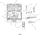
FIG. 1 is a schematic partial exploded perspective view of a steam cleaning device when an upper cover is opened according to an embodiment of the present disclosure.FIG. 2 is another schematic exploded perspective view of the steam cleaning device inFIG. 1 . As shown inFIGS. 1 and2 , asteam cleaning device 10 includes abox body 12, asteam generating device 18 and anaccessory 20. Thebox body 12 is internally provided with ahousing space 14, and thehousing space 14 includes a plurality of mutuallyindependent storage portions 16. Thesteam generating device 18 is arranged inside thebox body 12 and outside thehousing space 14. Theaccessory 20 is capable of being in fluid communication with or connected with thesteam generating device 18 and adapted to be correspondingly accommodated in the plurality of mutuallyindependent storage portions 16. - With this arrangement, it is beneficial for the accessory 20 to be independently stored in the
housing space 14 of thesteam cleaning device 10, and it is beneficial to prevent the accessory 20 from being damaged due to vibration and displacement. - The
steam generating device 18 may include a steam generator 17 (such as a boiler) and awater pump 19 that are in fluid communication with each other. - The
accessory 20 includes, for example, awater tank 28, asteam pipe 50, asteam handle 13, asteam nozzle 48, asteam brush 21, acircular brush 29, adetail nozzle 15, ablade 23, and the like. -
FIG. 3 is a schematic top view of the steam cleaning device inFIG. 1 . As shown inFIGS. 1 and3 , the plurality of mutuallyindependent storage portions 16 include afirst storage portion 30, asecond storage portion 38, athird storage portion 46, afourth storage portion 31, afifth storage portion 33, asixth storage portion 35, aseventh storage portion 37, and aneighth storage portion 39 separated from each other. - The
first storage portion 30 is adapted to accommodate thewater tank 28. Thesecond storage portion 38 is a portion of thehousing space 14 in addition to thefirst storage portion 30. Thethird storage portion 46 is adapted to accommodate thesteam pipe 50. Thefourth storage portion 31 is adapted to accommodate thesteam handle 13. Thefifth storage portion 33 is adapted to accommodate thesteam brush 21. Thesixth storage portion 35 is adapted to accommodate thecircular brush 29. Theseventh storage portion 37 is adapted to accommodate thedetail nozzle 15. Theeighth storage portion 39 is adapted to accommodate theblade 23. Thesteam nozzle 48 is adapted to be accommodated in the holding portion 44. - In some embodiments, the
housing space 14 is U-shaped. - With this arrangement, it is beneficial to obtain a high storage efficiency of the
housing space 14 and a compact structure of thesteam cleaning device 10. - The
housing space 14 may have any suitable configuration as long as it is suitable for the present disclosure. - As shown in
FIGS. 1 and2 , thebox body 12 includes anupper cover 22, alower cover 24 arranged below theupper cover 22 and amiddle frame 26 arranged between theupper cover 22 and thelower cover 24, and thehousing space 14 is arranged in themiddle frame 26. - With this arrangement, it is beneficial to obtain a more reasonable arrangement of various components and a more compact structure of the
steam cleaning device 10. - The
middle frame 26 may be provided with components such as anadjustment knob 25 and anindication panel 27. Theadjustment knob 25 may be used to adjust an amount of water, etc. Thedisplay panel 27 may be equipped with anindicator light 43 and apower switch 45, which may be used to indicate current operating status of thesteam cleaning device 10, thus making operation more convenient and controllable. - The
box body 12 may have any suitable configuration, and thehousing space 14 may be arranged at other suitable locations as long as it is suitable for the present disclosure. - In some embodiments, the
housing space 14 is arranged at an upper edge of themiddle frame 26, thesteam generating device 18 is arranged below themiddle frame 26, and thehousing space 14 partially surrounds thesteam generating device 18. - With this arrangement, it is beneficial to arrange the
steam generating device 18 in a central area of the entiresteam cleaning device 10 and ensure that the center of gravity of the entiresteam cleaning device 10 is centered, which can reduce wrist pain caused by eccentric handling. - Those skilled in the art can understand that the
steam generating device 18 is a heavy component in the entiresteam cleaning device 10. When thesteam generating device 18 is arranged in the central area of thesteam cleaning device 10, the center of gravity of the entiresteam cleaning device 10 is centered, which can reduce wrist pain caused by eccentric handling. -
FIG. 4 is a schematic view of the connection between the steam generating device and the water tank, the steam pipe and the steam handle of the steam cleaning device inFIG. 1 . As shown inFIGS. 1 ,3 and4 , in some embodiments, theaccessory 20 includes awater tank 28 that is in fluid communication with thesteam generating device 18, and the plurality of mutuallyindependent storage portions 16 include afirst storage portion 30 adapted to accommodate thewater tank 28. - With this arrangement, it is beneficial to use the
steam cleaning device 10 at any location and is not limited by a location of external water sources. - Referring to
FIG. 4 , specifically, an outlet of thewater tank 28 is communicated with an inlet of thewater pump 19 of thesteam generating device 18 to provide a water source for thesteam cleaning device 10. An outlet of thewater pump 19 is communicated with an inlet-outlet opening of theboiler 17 to provide water for theboiler 17. Theboiler 17 is communicated with the steam handle 13 through thesteam pipe 50 and transmits generated steam to thesteam handle 13. - The
water tank 28 is accommodated in thefirst storage portion 30 in the plurality of mutuallyindependent storage portions 16, which enables to use thesteam cleaning device 10 at arbitrary positions without being limited by the location of external water sources or using additional buckets for water supply. - In some embodiments, the
water tank 28 includes acover 32 made of an elastomer. - With this arrangement, it is beneficial for the
cover 32 to absorb the vibration generated when thewater tank 28 moves. - The
cover 32 may be arranged, for example, on a top side of thewater tank 28 and may have any suitable shape, such as a substantially circular shape. In addition, thecover 32 may have a sealing function to prevent water leakage in thewater tank 28. Thecover 32 may be manufactured by any suitable elastomer as long as it has the effect of absorbing vibration. For example, the elastomer may include Thermoplastic Elastomer (TPE), silicone, Ethylene Propylene Diene Monomer (EPDM), and the like. - In some embodiments, an inner side of the
upper cover 22 is provided with asupport rib 34 that abuts against an upper part of thecover 32. - With this arrangement, it is beneficial to provide a pre-tightening force for the
cover 32 of the water tank and fix thecover 32 of the water tank, which can stabilize thewater tank 28 during transportation and reduce damage caused by displacement. - The
support rib 34 may be arranged on the inner side of theupper cover 22 opposite to thecover 32 of the water tank and may have a shape corresponding to thecover 32. Thesupport rib 34 may be made of, for example, polycarbonate acrylonitrile butadiene styrene (PC-ABS). -
FIG. 5 is a schematic front view of the water tank of the steam cleaning device inFIG. 1 . As shown inFIGS. 3 and5 , thewater tank 28 includes ahandle portion 36 arranged outside a vertical line where a center of gravity G of thewater tank 28 is located. - With this arrangement, it is beneficial to rotate the
water tank 28 to a stable position through its own gravity during carrying, and it is beneficial for a carrying position of thewater tank 28 to be more stable. - The
water tank 28 may have an approximately rectangular shape. Thehandle portion 36 may be arranged, for example, at a top of thewater tank 28, for example, near thecover 32. Thehandle portion 36 may have a substantially convex structure extending along a partial top surface of thewater tank 28 away from aninlet 47 of thewater tank 28. - Referring to
FIG. 5 , in some embodiments, in a horizontal direction, thehandle portion 36 is arranged between the center of gravity G of thewater tank 28 and thecover 32. - With this arrangement, it is beneficial to keep the water in the
water tank 28 away from thecover 32 of the water tank during carrying and reduce the risk of water leakage. - In some embodiments, the
water tank 28 is adapted to be removably accommodated in thefirst storage portion 30. - With this arrangement, it is beneficial for operations such as filling and cleaning the
water tank 28. - In some embodiments, the
water tank 28 is adapted to be fixedly accommodated in thefirst storage portion 30. - With this arrangement, it is beneficial to stabilize the
water tank 28. -
FIG. 6 is a schematic top view of the middle frame and the lower cover of the steam cleaning device inFIG. 1 . As shown inFIG. 6 , in some embodiments, thehousing space 14 includes asecond storage portion 38 in addition to thefirst storage portion 30, and thesecond storage portion 38 is L-shaped. - With this arrangement, it is beneficial for the center of gravity of the entire
steam cleaning device 10 to be centered, which can reduce wrist pain caused by eccentric handling. -
FIG. 7 is a partial sectional view of the box body inFIG. 6 . As shown inFIGS. 6 and7 , a bottom of thefirst storage portion 30 is provided with areference surface 40 and aninlet 42, and a height H1 of theinlet 42 is greater than a height H2 of thereference surface 40 relative to anouter bottom surface 41 of thefirst storage portion 30. - With this arrangement, it is beneficial to reduce the risk of pollutants particles clogging the
inlet 42. - The
water tank 28 may become contaminated with contaminants, posing a risk of clogging theinlet 42. It is found through water spraying tests that when the height H1 of theinlet 42 is greater than the height H2 of thereference surface 40, pollutant particles are not easily accumulated in theinlet 42, reducing the risk of clogging theinlet 42. - Still referring to
FIG. 3 , in some embodiments, an inner side of theupper cover 22 is provided with a holding portion 44 made of a soft rubber material, and the plurality of mutuallyindependent storage portions 16 include athird storage portion 46 opposite to the holding portion 44. - With this arrangement, it is beneficial to reduce vibration during transportation.
- The soft rubber material may be any suitable rubber material as long as it can absorb vibration.
- Still referring to
FIGS. 1 and3 , theaccessory 20 includes asteam nozzle 48 and asteam pipe 50. The holding portion 44 is adapted to accommodate thesteam nozzle 48, and thethird storage portion 46 is adapted to accommodate thesteam pipe 50. - With this arrangement, it is beneficial to reduce vibration and damage of the
steam pipe 50 by the holding portion 44 absorbing vibration and contacting thesteam pipe 50. -
FIG. 8 is a schematic perspective view of the steam cleaning device inFIG. 1 when the upper cover is closed. In some embodiments, a connectingport 52 is provided on a front outer side of thelower cover 22, and the connectingport 52 is adapted to connect thesteam pipe 50. - With this arrangement, it is beneficial to disassemble the
steam pipe 50 and prevent damage to thesteam pipe 50 due to closing theupper cover 22 during the use of thesteam cleaning device 10. - Referring to
FIGS. 1 and8 , theaccessory 20 includes apower wire 54, and a side bottom of thebox body 12 is provided with awire outlet 56. Thepower wire 54 extends from thewire outlet 56 to an outer side of thebox body 12. - With this arrangement, it is beneficial to close the
upper cover 22 and use thesteam cleaning device 10 without damaging thepower wire 54. -
FIG. 9 is a schematic perspective view of a steam cleaning device when the upper cover is closed according to another embodiment of the present disclosure. As shown inFIG. 9 , at least one side of thebox body 12 is externally provided with amesh portion 56 for accommodating thepower wire 54. - With this arrangement, it is beneficial for the storage and protection of the
power wire 54. - The
power wire 54 is connected to thesteam cleaning device 10 through thewire outlet 56 arranged outside thebox body 12. Thewire outlet 56 may be arranged inside themesh portion 56. After use, thepower wire 54 may be conveniently stored in themesh portion 56, thereby obtaining additional protection from damage. - The
mesh portion 56 may be directly assembled outside a side portion of thebox body 12 through an assembly portion (not shown) arranged inside the side portion of thebox body 12. Thus, the assembly process is simple and material costs for thesteam cleaning device 10 can be saved. - In some embodiments, the
steam cleaning device 10 includes ahandle 58 arranged on an outer side of theupper cover 22. - With this arrangement, it is beneficial for the portability of the
steam cleaning device 10. - The
handle 58 may be approximately C-shaped and may be arranged, for example, in a center of the outer side of theupper cover 22. -
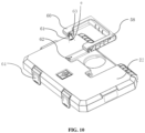
FIG. 10 is a schematic partial exploded perspective view of the upper cover of the steam cleaning device inFIG. 9 . In some embodiments, an end of thehandle 58 is provided with a mountingguide portion 60, and the outer side of theupper cover 22 is provided with a mountingportion 62 for matching with the mountingguide portion 60. - With this arrangement, it is beneficial to fix the
handle 58 on theupper cover 22 conveniently and easily. - The mounting
guide portion 60 may have a cylindrical shape with a notch on a side thereof. The mountingportion 62 may have a cylindrical shape and size corresponding to the mountingguide portion 60. - In some embodiments, the mounting
guide portion 60 has a mounting guide angle θ ranging from 30 to 40 degrees. - In the present disclosure, the mounting guide angle θ refers to an angle of two corresponding contact points between two edges of the notch on the side surface of the substantially cylindrical mounting
guide portion 60 and the substantially cylindrical mountingportion 62 relative totangent lines portion 62 respectively. - Referring to
FIGS. 1 ,3 and8-9 , in some embodiments, theupper cover 22 can be opened and closed relative to thelower cover 24. - With this arrangement, it is beneficial to obtain easy operation.
-
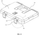
FIG. 11 is another schematic partial exploded perspective view of the upper cover of the steam cleaning device inFIG. 9 . As shown inFIG. 11 , in some embodiments, a front side of theupper cover 22 is provided with alock 64 suitable for locking thebox body 12. - With this arrangement, it is beneficial to close the
box body 12 stably and ensure convenient and smooth transportation of thesteam cleaning device 10. -
FIG. 12 is a schematic partially enlarged view of the upper cover of the steam cleaning device shown inFIG. 11 , in which the a step portion and the matching portion are enlargedly shown. As shown inFIGS. 11 and12 , in some embodiments, two sides of thelock 64 are provided with astep portion 66 respectively, and theupper cover 22 includes a matchingportion 68 for matching with thestep portion 66. - With this arrangement, it is beneficial to a locking strength.
- The
step portion 66 and the matchingportion 68 may have a step structure with a shape and size corresponding to each other. During transportation, thestep portion 66 and the matchingportion 68 contact each other to enhance the strength of thelock 64 and secure the locking of thebox body 12. - Still referring to
FIG. 9 , in some embodiments, a bottom of thebox body 12 is provided with auniversal wheel 70. - With this arrangement, it is beneficial to move the
steam cleaning device 10 conveniently and easily. - Although the present disclosure has been disclosed above, the present disclosure is not limited thereto. Any changes and modifications may be made by those skilled in the art without departing from the spirit and scope of the present disclosure, and the scope of the present disclosure should be determined by the appended claims.
Claims (25)
- A steam cleaning device (10), comprising:a box body (12) internally provided with a housing space (14), wherein the housing space (14) comprises a plurality of mutually independent storage portions (16);a steam generating device (18) arranged inside the box body (12) and outside the housing space (14); andan accessory (20) capable of being in fluid communication with or connected with the steam generating device (18) and adapted to be correspondingly accommodated in the plurality of mutually independent storage portions (16).
- The steam cleaning device (10) according to claim 1, wherein the housing space (14) is U-shaped.
- The steam cleaning device (10) according to claim 1 or 2, wherein the box body (12) comprises an upper cover (22), a lower cover (24) arranged below the upper cover (22) and a middle frame (26) arranged between the upper cover (22) and the lower cover (24), and the housing space (14) is arranged in the middle frame (26).
- The steam cleaning device (10) according to claim 3, wherein the housing space (14) is arranged at an upper edge of the middle frame (26), the steam generating device (18) is arranged below the middle frame (26), and the housing space (14) partially surrounds the steam generating device (18).
- The steam cleaning device (10) according to claim 3, wherein the accessory (20) comprises a water tank (28) that is in fluid communication with the steam generating device (18), and the plurality of mutually independent storage portions (16) comprise a first storage portion (30) adapted to accommodate the water tank (28).
- The steam cleaning device (10) according to claim 5, wherein the water tank (28) comprises a cover (32) made of an elastomer.
- The steam cleaning device (10) according to claim 6, wherein an inner side of the upper cover (22) is provided with a support rib (34) that abuts against an upper part of the cover (32).
- The steam cleaning device (10) according to claim 6, wherein the water tank (28) comprises a handle portion (36) arranged outside a vertical line (L) where a center of gravity (G) of the water tank (28) is located.
- The steam cleaning device (10) according to claim 8, wherein in a horizontal direction, the handle portion (36) is arranged between the center of gravity (G) of the water tank (28) and the cover (32).
- The steam cleaning device (10) according to claim 5, wherein the water tank (28) is adapted to be removably accommodated in the first storage portion (30).
- The steam cleaning device (10) according to claim 5, wherein the water tank (28) is adapted to be fixedly accommodated in the first storage portion (30).
- The steam cleaning device (10) according to claim 5, wherein the housing space (14) comprises a second storage portion (38) in addition to the first storage portion (30), and the second storage portion (38) is L-shaped.
- The steam cleaning device (10) according to claim 5, wherein a bottom of the first storage portion (30) is provided with a reference surface (40) and an inlet (42), and a height (H1) of the inlet (42) is greater than a height (H2) of the reference surface (40) relative to an outer bottom surface (41) of the first storage portion (30).
- The steam cleaning device (10) according to claim 3, wherein an inner side of the upper cover (22) is provided with a holding portion (44) made of a soft rubber material, and the plurality of mutually independent storage portions (16) comprise a third storage portion (46) opposite to the holding portion (44).
- The steam cleaning device (10) according to claim 14, wherein the accessory (20) comprises a steam nozzle (48) and a steam pipe (50), the holding portion (44) is adapted to accommodate the steam nozzle (48), and the third storage portion (46) is adapted to accommodate the steam pipe (50).
- The steam cleaning device (10) according to claim 15, wherein a front outer side of the lower cover (22) is provided with a connecting port (52) for connecting the steam pipe (50).
- The steam cleaning device (10) according to claim 1, wherein the accessory (20) comprises a power wire (54), a side bottom of the box body (12) is provided with a wire outlet (56), and the power wire (54) extends from the wire outlet (56) to an outer side of the box body (12).
- The steam cleaning device (10) according to claim 17, wherein at least one side of the box body (12) is externally provided with a mesh portion (56) for accommodating the power wire (54).
- The steam cleaning device (10) according to claim 3, further comprising a handle (58) arranged on an outer side of the upper cover (22).
- The steam cleaning device (10) according to claim 19, wherein an end of the handle (58) is provided with a mounting guide portion (60), and the outer side of the upper cover (22) is provided with a mounting portion (62) for matching with the mounting guide portion (60).
- The steam cleaning device (10) according to claim 20, wherein the mounting guide portion (60) has a mounting guide angle θ ranging from 30 to 40 degrees.
- The steam cleaning device (10) according to claim 3, wherein the upper cover (22) is capable of being opened and closed relative to the lower cover (24).
- The steam cleaning device (10) according to claim 22, wherein a front side of the upper cover (22) is provided with a lock (64) for locking the box body (12).
- The steam cleaning device (10) according to claim 23, wherein two sides of the lock (64) are provided with a step portion (66) respectively, and the upper cover (22) comprises a matching portion (68) for matching with the step portion (66).
- The steam cleaning device (10) according to claim 1, wherein a bottom of the box body (12) is provided with a universal wheel (70).
Applications Claiming Priority (2)
| Application Number | Priority Date | Filing Date | Title |
|---|---|---|---|
| CN202011219389.0A CN114433540A (en) | 2020-11-04 | 2020-11-04 | Steam cleaning device |
| PCT/CN2021/125453 WO2022095717A1 (en) | 2020-11-04 | 2021-10-22 | Steam cleaning device |
Publications (2)
| Publication Number | Publication Date |
|---|---|
| EP4241896A1 true EP4241896A1 (en) | 2023-09-13 |
| EP4241896A4 EP4241896A4 (en) | 2024-10-09 |
Family
ID=81361586
Family Applications (1)
| Application Number | Title | Priority Date | Filing Date |
|---|---|---|---|
| EP21888414.6A Pending EP4241896A4 (en) | 2020-11-04 | 2021-10-22 | STEAM CLEANER |
Country Status (3)
| Country | Link |
|---|---|
| EP (1) | EP4241896A4 (en) |
| CN (1) | CN114433540A (en) |
| WO (1) | WO2022095717A1 (en) |
Family Cites Families (20)
| Publication number | Priority date | Publication date | Assignee | Title |
|---|---|---|---|---|
| JP2002253648A (en) * | 2001-02-28 | 2002-09-10 | Olympus Optical Co Ltd | Used endoscope regeneration processing unit |
| CN101245553A (en) * | 2007-02-15 | 2008-08-20 | 灿坤实业股份有限公司 | steam ironing machine |
| CN102858470B (en) * | 2010-04-15 | 2015-11-25 | 阿尔弗雷德·凯驰两合公司 | Steam appliance |
| CN202279977U (en) * | 2011-10-17 | 2012-06-20 | 莱克电气股份有限公司 | Steam electric appliance having high-pressure cleaning function |
| CN202860891U (en) * | 2012-10-25 | 2013-04-10 | 甘继东 | Steam washing machine |
| CN104438181B (en) * | 2014-12-05 | 2016-08-24 | 山东蓝伞国际科技开发有限公司 | Water-heater cleaning machine |
| CN207013352U (en) * | 2017-06-01 | 2018-02-16 | 钱海林 | A kind of household electrical appliances HIGH TEMPERATURE PURGE equipment |
| CN208033150U (en) * | 2018-01-25 | 2018-11-02 | 张石磊 | A kind of high-pressure steam-cleaning machine |
| CN208058805U (en) * | 2018-03-14 | 2018-11-06 | 广东美的厨房电器制造有限公司 | Container, steam generating system and steam sterilization cabinet |
| CN208179480U (en) * | 2018-03-21 | 2018-12-04 | 宁波惠捷塑业有限公司 | A kind of portable tool box |
| CN208482885U (en) * | 2018-04-12 | 2019-02-12 | 中山市必归来金属科技有限公司 | A multifunctional steam cleaning machine |
| CN208912641U (en) * | 2018-08-30 | 2019-05-31 | 深圳市宜家卫士科技有限公司 | A fully intelligent household appliance cleaning machine with high efficiency and high safety performance |
| CN109365429A (en) * | 2018-10-13 | 2019-02-22 | 东莞市志诚电器有限公司 | Steam pulse floor heating all-in-one machine |
| CN209341304U (en) * | 2018-12-19 | 2019-09-03 | 刘楚萱 | A kind of integrated cook utensil of moveable centralization |
| CN210304737U (en) * | 2019-01-25 | 2020-04-14 | 杭州非同工业设计有限公司 | Household electrical appliances cleaning machine |
| CN211146435U (en) * | 2019-10-25 | 2020-07-31 | 杜志伟 | Steam generating device and steam cleaning equipment |
| CN110844373A (en) * | 2019-12-02 | 2020-02-28 | 中车西安车辆有限公司 | Steam heating device for tank container |
| CN211443231U (en) * | 2019-12-13 | 2020-09-08 | 福清市卡托乐科技有限公司 | Storage device for electronic communication antenna |
| CN211674076U (en) * | 2020-01-20 | 2020-10-16 | 浙江维朋制冷设备有限公司 | Steam cleaning equipment |
| CN215142541U (en) * | 2020-11-04 | 2021-12-14 | 阿尔弗雷德·卡赫欧洲两合公司 | Steam cleaning device |
-
2020
- 2020-11-04 CN CN202011219389.0A patent/CN114433540A/en active Pending
-
2021
- 2021-10-22 EP EP21888414.6A patent/EP4241896A4/en active Pending
- 2021-10-22 WO PCT/CN2021/125453 patent/WO2022095717A1/en not_active Ceased
Also Published As
| Publication number | Publication date |
|---|---|
| WO2022095717A1 (en) | 2022-05-12 |
| CN114433540A (en) | 2022-05-06 |
| EP4241896A4 (en) | 2024-10-09 |
Similar Documents
| Publication | Publication Date | Title |
|---|---|---|
| US20090173753A1 (en) | Pressurized fluid dispenser | |
| CN104519777B (en) | Vacuum cleaner | |
| CA2464222A1 (en) | A portable cleaning machine | |
| CN221997738U (en) | A cleaning device | |
| CN105392402A (en) | Portable hard-surface cleaning device | |
| KR20240132045A (en) | Reception devices and automatic cleaning devices | |
| CN105392403A (en) | Portable hard-surface cleaning appliance | |
| CN217471897U (en) | Sewage system of a fabric cleaning machine and fabric cleaning machine | |
| KR940003678A (en) | Cleanroom tool chamber | |
| CN215142541U (en) | Steam cleaning device | |
| ES3037796T3 (en) | Filtration device having a latch mechanism adapter | |
| RU2238023C2 (en) | Steam-jet apparatus for vacuum cleaner (versions) | |
| CN114468885A (en) | Surface cleaning apparatus | |
| RU2264157C1 (en) | Apparatus for connecting hose to vacuum cleaner and vacuum cleaner for wet/dry cleaning | |
| US20250098924A1 (en) | Self-cleaning dust-collecting base and dust-collecting system | |
| WO2022095717A1 (en) | Steam cleaning device | |
| US12433462B2 (en) | Cleaning robot and robot system | |
| CN216907850U (en) | Tank part and surface cleaning equipment | |
| CN216907851U (en) | Surface cleaning apparatus | |
| KR102205171B1 (en) | Multipurpose wet vacuum cleaner | |
| CN223169660U (en) | Cleaning apparatus | |
| CN217118346U (en) | Maintenance base station and cleaning robot system | |
| CN203723987U (en) | Small-size fruit and vegetable cleaning device | |
| CN224055930U (en) | Dirt storage bin and cleaning equipment | |
| CN221599817U (en) | Float and cleaning device |
Legal Events
| Date | Code | Title | Description |
|---|---|---|---|
| STAA | Information on the status of an ep patent application or granted ep patent |
Free format text: STATUS: THE INTERNATIONAL PUBLICATION HAS BEEN MADE |
|
| PUAI | Public reference made under article 153(3) epc to a published international application that has entered the european phase |
Free format text: ORIGINAL CODE: 0009012 |
|
| STAA | Information on the status of an ep patent application or granted ep patent |
Free format text: STATUS: REQUEST FOR EXAMINATION WAS MADE |
|
| 17P | Request for examination filed |
Effective date: 20230503 |
|
| AK | Designated contracting states |
Kind code of ref document: A1 Designated state(s): AL AT BE BG CH CY CZ DE DK EE ES FI FR GB GR HR HU IE IS IT LI LT LU LV MC MK MT NL NO PL PT RO RS SE SI SK SM TR |
|
| DAV | Request for validation of the european patent (deleted) | ||
| DAX | Request for extension of the european patent (deleted) | ||
| A4 | Supplementary search report drawn up and despatched |
Effective date: 20240909 |
|
| RIC1 | Information provided on ipc code assigned before grant |
Ipc: A47L 11/34 20060101ALI20240903BHEP Ipc: A47L 11/40 20060101ALI20240903BHEP Ipc: A61L 2/07 20060101ALI20240903BHEP Ipc: B08B 13/00 20060101ALI20240903BHEP Ipc: B08B 1/00 20060101ALI20240903BHEP Ipc: B08B 3/02 20060101AFI20240903BHEP |
|
| P01 | Opt-out of the competence of the unified patent court (upc) registered |
Free format text: CASE NUMBER: APP_61156/2024 Effective date: 20241114 |