EP4241870B1 - Filter system - Google Patents
Filter system Download PDFInfo
- Publication number
- EP4241870B1 EP4241870B1 EP22305269.7A EP22305269A EP4241870B1 EP 4241870 B1 EP4241870 B1 EP 4241870B1 EP 22305269 A EP22305269 A EP 22305269A EP 4241870 B1 EP4241870 B1 EP 4241870B1
- Authority
- EP
- European Patent Office
- Prior art keywords
- filter element
- filter
- fluid
- actuator
- fluid outlet
- Prior art date
- Legal status (The legal status is an assumption and is not a legal conclusion. Google has not performed a legal analysis and makes no representation as to the accuracy of the status listed.)
- Active
Links
Images


Classifications
-
- B—PERFORMING OPERATIONS; TRANSPORTING
- B60—VEHICLES IN GENERAL
- B60H—ARRANGEMENTS OF HEATING, COOLING, VENTILATING OR OTHER AIR-TREATING DEVICES SPECIALLY ADAPTED FOR PASSENGER OR GOODS SPACES OF VEHICLES
- B60H3/00—Other air-treating devices
- B60H3/06—Filtering
- B60H3/0608—Filter arrangements in the air stream
-
- B—PERFORMING OPERATIONS; TRANSPORTING
- B01—PHYSICAL OR CHEMICAL PROCESSES OR APPARATUS IN GENERAL
- B01D—SEPARATION
- B01D46/00—Filters or filtering processes specially modified for separating dispersed particles from gases or vapours
- B01D46/10—Particle separators, e.g. dust precipitators, using filter plates, sheets or pads having plane surfaces
-
- B—PERFORMING OPERATIONS; TRANSPORTING
- B01—PHYSICAL OR CHEMICAL PROCESSES OR APPARATUS IN GENERAL
- B01D—SEPARATION
- B01D46/00—Filters or filtering processes specially modified for separating dispersed particles from gases or vapours
- B01D46/0039—Filters or filtering processes specially modified for separating dispersed particles from gases or vapours with flow guiding by feed or discharge devices
- B01D46/0041—Filters or filtering processes specially modified for separating dispersed particles from gases or vapours with flow guiding by feed or discharge devices for feeding
-
- B—PERFORMING OPERATIONS; TRANSPORTING
- B01—PHYSICAL OR CHEMICAL PROCESSES OR APPARATUS IN GENERAL
- B01D—SEPARATION
- B01D46/00—Filters or filtering processes specially modified for separating dispersed particles from gases or vapours
- B01D46/42—Auxiliary equipment or operation thereof
- B01D46/4236—Reducing noise or vibration emissions
-
- B—PERFORMING OPERATIONS; TRANSPORTING
- B01—PHYSICAL OR CHEMICAL PROCESSES OR APPARATUS IN GENERAL
- B01D—SEPARATION
- B01D46/00—Filters or filtering processes specially modified for separating dispersed particles from gases or vapours
- B01D46/42—Auxiliary equipment or operation thereof
- B01D46/44—Auxiliary equipment or operation thereof controlling filtration
- B01D46/442—Auxiliary equipment or operation thereof controlling filtration by measuring the concentration of particles
-
- B—PERFORMING OPERATIONS; TRANSPORTING
- B01—PHYSICAL OR CHEMICAL PROCESSES OR APPARATUS IN GENERAL
- B01D—SEPARATION
- B01D46/00—Filters or filtering processes specially modified for separating dispersed particles from gases or vapours
- B01D46/42—Auxiliary equipment or operation thereof
- B01D46/44—Auxiliary equipment or operation thereof controlling filtration
- B01D46/444—Auxiliary equipment or operation thereof controlling filtration by flow measuring
-
- B—PERFORMING OPERATIONS; TRANSPORTING
- B60—VEHICLES IN GENERAL
- B60H—ARRANGEMENTS OF HEATING, COOLING, VENTILATING OR OTHER AIR-TREATING DEVICES SPECIALLY ADAPTED FOR PASSENGER OR GOODS SPACES OF VEHICLES
- B60H3/00—Other air-treating devices
- B60H3/06—Filtering
- B60H3/0608—Filter arrangements in the air stream
- B60H3/0625—Filter arrangements in the air stream with provisions for by-passing the filter element
-
- B—PERFORMING OPERATIONS; TRANSPORTING
- B01—PHYSICAL OR CHEMICAL PROCESSES OR APPARATUS IN GENERAL
- B01D—SEPARATION
- B01D2273/00—Operation of filters specially adapted for separating dispersed particles from gases or vapours
- B01D2273/10—Allowing a continuous bypass of at least part of the flow, e.g. of secondary air, vents
-
- B—PERFORMING OPERATIONS; TRANSPORTING
- B01—PHYSICAL OR CHEMICAL PROCESSES OR APPARATUS IN GENERAL
- B01D—SEPARATION
- B01D2273/00—Operation of filters specially adapted for separating dispersed particles from gases or vapours
- B01D2273/14—Filters which are moved between two or more positions, e.g. by turning, pushing
-
- B—PERFORMING OPERATIONS; TRANSPORTING
- B60—VEHICLES IN GENERAL
- B60H—ARRANGEMENTS OF HEATING, COOLING, VENTILATING OR OTHER AIR-TREATING DEVICES SPECIALLY ADAPTED FOR PASSENGER OR GOODS SPACES OF VEHICLES
- B60H3/00—Other air-treating devices
- B60H3/06—Filtering
- B60H3/0608—Filter arrangements in the air stream
- B60H2003/065—Details for holding filter elements in position
-
- B—PERFORMING OPERATIONS; TRANSPORTING
- B60—VEHICLES IN GENERAL
- B60H—ARRANGEMENTS OF HEATING, COOLING, VENTILATING OR OTHER AIR-TREATING DEVICES SPECIALLY ADAPTED FOR PASSENGER OR GOODS SPACES OF VEHICLES
- B60H3/00—Other air-treating devices
- B60H3/06—Filtering
- B60H2003/0683—Filtering the quality of the filter or the air being checked
Definitions
- the invention relates to a filter system comprising a housing with a fluid inlet and a fluid outlet and a filter element being accommodated in the housing for filtering a fluid flowing from the fluid inlet to the fluid outlet, in particular for cabin air filter applications of a vehicle.
- Smart cabin air filter systems will become more and more used by vehicle manufacturers. Smart means that the air quality (particulate matter/CO 2 /humidity) will be controlled to the necessary need in order to optimize the power consumption of the vehicle.
- High filtration requirements means the use of so-called high efficiency particulate air (HEPA) filters with high pressure drop and thus higher consumption of the blower.
- HEPA high efficiency particulate air
- Smart cabin air filter systems are often localized in a very compact space inside the vehicle and so sometimes a simple bypass flap solution cannot be implemented for space and aeraulic performance reasons.
- US 7,900,694 B2 discloses an air conditioner for a vehicle.
- the air conditioner includes: an air conditioner case having an evaporator and a heater core installed therein and having a blower installed at an inlet thereof; a movable filter for moving between an air-filtering location and an air-nonfiltering location of the air conditioner case; a judging means for judging whether air blown by the blower inside the air conditioner case is contaminated; and a driving means for moving the movable filter to the air-filtering location when the judging means determines that the air is contaminated and to the air-non-filtering location when the judging means determines that the air is not contaminated.
- a filter system comprising a housing with a fluid inlet and a fluid outlet and a filter element being accommodated in the housing for filtering a fluid flowing from the fluid inlet to the fluid outlet, wherein an actuator is provided to rotate the filter element between a first position and a second position in the housing, wherein the fluid outlet is sealed by the filter element when the filter element is in the first position and wherein the fluid outlet is open for unfiltered fluid passage from the fluid inlet to the fluid outlet when the filter element is in the second position, wherein a locking means is provided to lock the filter element in the first position.
- a filter system comprising a housing with a fluid inlet and a fluid outlet and a filter element being accommodated in the housing for filtering a fluid flowing from the fluid inlet to the fluid outlet, wherein an actuator is provided to rotate the filter element between a first position and a second position in the housing.
- the fluid outlet is sealed by the filter element when the filter element is in the first position and wherein the fluid outlet is open for unfiltered fluid passage from the fluid inlet to the fluid outlet when the filter element is in the second position.
- a locking means is provided to lock the filter element in the first position.
- the actuator may be connected to a lever arrangement comprising at least two linked levers for rotating the filter element, wherein a first lever is driven by the actuator and a second lever is linked to a rotational joint of the filter element.
- the lever arrangement advantageously enables rotation of the filter element with a low torque und facilitates on the other side the establishment of locking means for locking the filter element in the first position.
- the locking means may be locking the filter element in the first position in a self-locked manner when the lever arrangement is rotated beyond a dead center position of the two levers when pressing the filter element against the fluid outlet. This enables for moving the filter element between the two positions with a low consumption of energy necessary to maintain the position of the filter element in the end position, where the actuator even may be deactivated.
- the filter system comprises a bypass solution for smart cabin air filter system applications.
- the focus lies on the bypass of an HEPA filter element to increase the filter service life and to reduce the pressure drop of the filter system.
- the solution may be part of the power consumption optimization with an intelligent monitoring of the air quality inside and outside the vehicle. When the outside and inside air quality is at a good level, the HEPA filter is not needed. Therefore the filter system may be bypassed, reducing the pressure drop and so the power consumption of the vehicle. The power consumption is becoming more and more important with battery electric vehicles.
- the proposed filter system enables to rotate the filter frame of the filter element with a reduced needed torque and enables with a locking system to always maintain pressure on the gasket to ensure a good and robust sealing.
- the filter system comprises four rotating shafts in total, two driving shafts and two driven shafts.
- the two driven shafts are linked together by a lever arrangement that transmit the torque from the actuator to the driving shafts.
- the driven shafts are then making the link between the driving shafts and the frame of the filter element holding the filter body.
- the proposed filter system thus offers a significant advantage compared to current heating ventilation and air conditioning (HVAC) application filter systems where a bypass of the filter system is done using flaps where the filter element always stays in a fixed position.
- HVAC heating ventilation and air conditioning
- the proposed filter system may be positioned in narrow spaces and the aeraulic section optimized, thus optimizing the pressure drop and again the consumption of the vehicle.
- the filter system can deactivate the actuator while maintaining the gasket of the seat of the filter element compressed.
- the kinematic movement of the rotating shaft also enables a reduced amount of torque to both put the frame of the filter element in motion and compress the sealing.
- a reduced output torque for the actuator implies a reduced cost for such an actuator.
- the invention also enables to implement a bypass design when the vehicle environment is very complex.
- the locking means is based on a current concept of injection press locking systems.
- the filter element is locked in the closed position to maintain a good sealing and still is reversible by the actuator.
- the filter element may be provided with a rotary axis being extended parallel to a longitudinal side of the filter element for being rotated between the first position and the second position along the rotary axis.
- the filter element may advantageously be moved to the fluid outlet in order to filter the passing fluid or removed in order to establish a bypass mode for the passing fluid.
- the filter element may comprise a frame accommodating a filter body, in particular a replaceable filter body, wherein a fluid passage through the filter body is transverse to a plane spanned by the longitudinal side and a transverse side of the filter element.
- a filter body in particular a replaceable filter body, wherein a fluid passage through the filter body is transverse to a plane spanned by the longitudinal side and a transverse side of the filter element.
- a turning shaft may be connected to the actuator, in particular an electric actuator, for being driven by the actuator, the turning shaft being located parallel to the longitudinal side of the filter element for rotating the filter element between the first and the second position.
- an electric actuator may be used for driving the turning shaft, but principally other actuators like e.g. vacuum actuators may also be implemented for rotation the filter element.
- a gasket may be arranged circumferencing the fluid outlet and/or the filter element for sealing the filter element in the first position against the fluid outlet.
- the filter element may advantageously be sealed to the fluid outlet in order to avoid leakage during filtering the passing fluid.
- the actuator may be deactivated when the filter element is in the first position or in the second position.
- the locking means still maintain the filter element in the chosen position with the fluid outlet closed by the filter element for filtering the passing fluid or with the fluid outlet open for bypassing the filter element.
- a sealing shape may be provided on the fluid outlet and/or on the filter element.
- the sealing shape serves for a tight sealing of the filter element against the fluid outlet and may be provided on either the housing part of the fluid outlet or on the filter element interface to the fluid outlet or on both sides.
- the actuator may comprise a position sensor for determining the position of the filter element.
- the activator may be deactivated when the filter element is in the chosen position.
- a fluid quality sensor may be provided so that the filter element is rotatable between the first and the second position depending on a quality of the fluid passing through the filter element, in particular depending on at least a signal of the fluid quality sensor.
- the fluid may be filtered by the filter element in the first position when the quality of the fluid, in particular air in the case of cabin air filtering, is below a given threshold.
- the filter element may be moved to the second position in order to bypass the filter element and let the fluid pass unfiltered from the fluid inlet to the fluid outlet.
- an elastic means may be arranged at the filter element and/or the housing for absorbing movements of the filter element in the second position.
- the elastic means may reduce vibrations of the filter element in the second position, thus reducing noise caused by the vibrations as well as increasing service lifetime of the filter element.
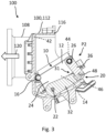
- Figure 1 shows a top view with open housing 110 of a filter system 100 with a filter element 10 in a second position P2 according to an embodiment of the invention and an intersection plane B-B marked.
- Figure 2 shows a three-dimensional view of the filter system 100 of Figure 1 .
- Figure 3 a longitudinal cut view of the filter system 100 in the intersection plane B-B according to Figure 1 is shown.
- the filter system 100 comprises a housing 110 with a fluid inlet 102 and a fluid outlet 108.
- the housing 110 comprises a first housing part 112, where the fluid outlet 108 is located and a second housing part 114 which is removed in the Figures 1 to 3 .
- the fluid inlet 102 may be realized on a side of the housing 110 in the first housing part 112 or in the second housing part 114 and is not visible in the Figures 1 to 3 .
- the fluid inlet 102 may receive the fluid from an ambient filter as is used frequently for filtering cabin air in vehicles.
- the filter system 100 further comprises a filter element 10 being accommodated in the housing 110 for filtering a fluid flowing from the fluid inlet 102 to the fluid outlet 108.
- An actuator 30 is provided to rotate the filter element 10 between a first position P1 and a second position P2 in the housing 110.
- the actuator 30 is marked in the Figures only as a symbol and may be significantly larger in reality.
- the actuator 30 may be realized as an electric actuator 30 with an electric drive. Principally other actuators, like e.g. vacuum driven actuators as used frequently in vehicles, may also be used.
- the filter element 10 may be implemented as a HEPA filter for high quality filtering of a cabin air filter system.
- the filter element 10 comprises a frame 12 accommodating a filter body 14, in particular a replaceable filter body 14, wherein a fluid passage through the filter body 14 is transverse to a plane spanned by the longitudinal side 18 and a transverse side 24 of the filter element 10.
- the fluid outlet 108 is sealed by the filter element 10 when the filter element 10 is in the first position P1 which means that the fluid passing from the fluid inlet 102 to the fluid outlet 108 is filtered by the filter element 10.
- the fluid flow 120 is indicated by a big arrow.
- the fluid outlet 108 is open for unfiltered fluid passage from the fluid inlet 102 to the fluid outlet 108 when the filter element 10 is in the second position P2.
- the filter element 10 is in the second position P2 which means that the filter element 10 is bypassed by the fluid flowing unfiltered from the fluid inlet 102 to the fluid outlet 108.
- the filter element 10 is provided with a rotary axis 16, which is to be seen in Figure 3 , being extended parallel to a longitudinal side 18 of the filter element 10 for being rotated between the first position P1 and the second position P2 along the rotary axis 16.
- a turning shaft 22 is connected to the actuator 30 for being driven by the actuator 30.
- the turning shaft 22 is located parallel to the longitudinal side 18 of the filter element 10 for rotating the filter element 10 between the first and the second position P1, P2.
- the actuator 30 is connected via the turning shaft 22 to a lever arrangement 31 comprising at least two linked levers 32, 34, 36, 38 for rotating the filter element 10, wherein a first lever 32, 34 is driven by the actuator 30 and a second lever 36, 38 is linked to a rotational joint 26, 28 of the filter element 10.
- the first lever 32 is fixed to the turning shaft 22 on one side and linked via a rotational joint 48 to the second lever 36 on the other side.
- the second lever 36 is linked via the rotational joint 26 to the frame 12 of the filter element 10.
- the frame 12 of the filter element 10 is rotatable via the rotary axis 16 in one corner of the frame 12.
- the lever arrangement 31 may comprise a second set of levers 34, 38 as is to be seen in Figure 2 . This may be realized with filter elements 10 with larger dimensions of the longitudinal side 18. With smaller filter elements 10 only one set of levers 32, 34, 36, 38 on one transverse side 24 of the frame 12 may be sufficient for driving the filter element 10. In Figure 1 the second set of levers 34, 38 is omitted.
- a fluid quality sensor may be provided so that the filter element 10 is rotatable between the first and the second position P1, P2 depending on a quality of the fluid passing through the filter element 10, in particular depending on at least a signal of the fluid quality sensor.
- the fluid outlet 108 may be opened for fresh air supply or closed with the filter element 10 for filtering the air depending on the quality of the air surrounding the vehicle.
- An elastic means 46 may arranged at the filter element 10 and/or the housing 110 for absorbing movements of the filter element 10 in the second position P2.
- vibrations of the vehicle exciting the filter element 10 especially when the filter element 10 is in the second position P2 may be reduced in order to prolong the lifetime of the filter element 10.
- Equally possible noise may be reduced by the elastic means 46 when the filter element 10 is located in the second position P2.
- a gasket 42 may be arranged circumferencing the fluid outlet 108 and/or the filter element 10 for sealing the filter element 10 in the first position P1 against the fluid outlet 108.
- a sealing shape 44 for tight sealing may be provided on the fluid outlet 108 and/or on the filter element 10.
- FIG 4 shows a longitudinal cut view of a filter system 100 with a closed housing 110 according to a further embodiment of the invention.
- the filter system 100 is quite similar to the embodiment shown in Figures 1 to 3 and therefore does not need further explanation.
- the filter system 100 shown in Figure 4 exhibits a closed housing 110 comprising a first housing part 112 with the fluid outlet 108 and a second housing part 114.
- the first housing part 112 and the second housing part 114 are tightly sealed with a circumferencing gasket 116 in the first housing part 112.
- the gasket 116 is explicitly to be seen in the Figures 1 and 2 .
- a locking means 20, based on the lever arrangement 31, is provided to lock the filter element 20 in the first position P1.
- the locking means 20 is locking the filter element 10 in the first position P1 in a self-locked manner when the lever arrangement 31 is rotated beyond a dead center position 40 of the two levers 32, 34, 36, 38 when pressing the filter element 10 against the fluid outlet 108. Therefore the actuator 30 may be deactivated when the filter element 10 is in the first position P1 or in the second position P2 for saving consumption of the vehicle.
- the actuator 30 may comprise an integrated position sensor for determining the position P1, P2 of the filter element 10.
- the locking means 20 advantageously enables to maintain a pressure between both sides of the frame 12 of the filter element 10 for better sealing in the first position P1 and reducing vibration issues on the filter element 10.
- Figure 5 shows a top view with open housing 110 of the filter system 100 according to Figure 1 with the filter element 10 in a dead center position according to an embodiment of the invention and an intersection plane C-C marked.
- Figure 6 shows a three-dimensional view of the filter system 100 of Figure 5
- Figure 7 shows a longitudinal cut view of the filter system 100 in the intersection plane C-C according to Figure 5 .
- the two levers 32, 36 of the lever arrangement 31 are positioned along a straight line, thus pressing the filter element 10 at the end with the rotational joint 26 deeper into the gasket 42 than on the lower end at the rotary axis 16.
- This dead center position thus is an instable position of the lever arrangement 31 realized as locking means 20. Any further rotation of the turning shaft 22 will snap the lever arrangement into the first position of the filter element 10 which is to be seen in the Figures 8 to 10 .
- Figure 8 shows a top view with open housing 110 of the filter system 100 according to Figure 1 with the filter element 10 in a first position P1 according to an embodiment of the invention and an intersection plane A-A marked.
- Figure 9 shows a three-dimensional view of the filter system 100 of Figure 8 , whereas in Figure 10 a longitudinal cut view of the filter system 100 in the intersection plane A-A according to Figure 8 is shown.
- the two levers 32, 36 are in a position characterized by an angle 52 being greater than zero.
- the frame 12 of the filter element 10 is located parallel to the section plane of the housing part 112 serving as an interface of the fluid outlet 108 for the filter element 10.
Landscapes
- Chemical & Material Sciences (AREA)
- Chemical Kinetics & Catalysis (AREA)
- Engineering & Computer Science (AREA)
- Mechanical Engineering (AREA)
- Filtering Of Dispersed Particles In Gases (AREA)
Description
- The invention relates to a filter system comprising a housing with a fluid inlet and a fluid outlet and a filter element being accommodated in the housing for filtering a fluid flowing from the fluid inlet to the fluid outlet, in particular for cabin air filter applications of a vehicle.
- Smart cabin air filter systems will become more and more used by vehicle manufacturers. Smart means that the air quality (particulate matter/CO2/humidity) will be controlled to the necessary need in order to optimize the power consumption of the vehicle. High filtration requirements means the use of so-called high efficiency particulate air (HEPA) filters with high pressure drop and thus higher consumption of the blower. When the air quality inside the vehicle is at the required level, HEPA filtration is not needed anymore and the need comes to bypass the filter system. Smart cabin air filter systems are often localized in a very compact space inside the vehicle and so sometimes a simple bypass flap solution cannot be implemented for space and aeraulic performance reasons.
-
US 7,900,694 B2 discloses an air conditioner for a vehicle. The air conditioner includes: an air conditioner case having an evaporator and a heater core installed therein and having a blower installed at an inlet thereof; a movable filter for moving between an air-filtering location and an air-nonfiltering location of the air conditioner case; a judging means for judging whether air blown by the blower inside the air conditioner case is contaminated; and a driving means for moving the movable filter to the air-filtering location when the judging means determines that the air is contaminated and to the air-non-filtering location when the judging means determines that the air is not contaminated. - It is an object of the invention to provide a filter system with an improved filter service life.
- The aforementioned object is achieved according to one aspect of the invention by a filter system comprising a housing with a fluid inlet and a fluid outlet and a filter element being accommodated in the housing for filtering a fluid flowing from the fluid inlet to the fluid outlet, wherein an actuator is provided to rotate the filter element between a first position and a second position in the housing, wherein the fluid outlet is sealed by the filter element when the filter element is in the first position and wherein the fluid outlet is open for unfiltered fluid passage from the fluid inlet to the fluid outlet when the filter element is in the second position, wherein a locking means is provided to lock the filter element in the first position.
- Advantageous embodiments and advantages of the invention are described in the further claims, the description and the drawings.
- According to a first aspect of the invention, a filter system is proposed, comprising a housing with a fluid inlet and a fluid outlet and a filter element being accommodated in the housing for filtering a fluid flowing from the fluid inlet to the fluid outlet, wherein an actuator is provided to rotate the filter element between a first position and a second position in the housing. The fluid outlet is sealed by the filter element when the filter element is in the first position and wherein the fluid outlet is open for unfiltered fluid passage from the fluid inlet to the fluid outlet when the filter element is in the second position. A locking means is provided to lock the filter element in the first position.
- The actuator may be connected to a lever arrangement comprising at least two linked levers for rotating the filter element, wherein a first lever is driven by the actuator and a second lever is linked to a rotational joint of the filter element. The lever arrangement advantageously enables rotation of the filter element with a low torque und facilitates on the other side the establishment of locking means for locking the filter element in the first position.
- The locking means may be locking the filter element in the first position in a self-locked manner when the lever arrangement is rotated beyond a dead center position of the two levers when pressing the filter element against the fluid outlet. This enables for moving the filter element between the two positions with a low consumption of energy necessary to maintain the position of the filter element in the end position, where the actuator even may be deactivated.
- The filter system according to an embodiment of the invention comprises a bypass solution for smart cabin air filter system applications. The focus lies on the bypass of an HEPA filter element to increase the filter service life and to reduce the pressure drop of the filter system. The solution may be part of the power consumption optimization with an intelligent monitoring of the air quality inside and outside the vehicle. When the outside and inside air quality is at a good level, the HEPA filter is not needed. Therefore the filter system may be bypassed, reducing the pressure drop and so the power consumption of the vehicle. The power consumption is becoming more and more important with battery electric vehicles. The proposed filter system enables to rotate the filter frame of the filter element with a reduced needed torque and enables with a locking system to always maintain pressure on the gasket to ensure a good and robust sealing.
- The filter system comprises four rotating shafts in total, two driving shafts and two driven shafts. The two driven shafts are linked together by a lever arrangement that transmit the torque from the actuator to the driving shafts. The driven shafts are then making the link between the driving shafts and the frame of the filter element holding the filter body.
- The proposed filter system thus offers a significant advantage compared to current heating ventilation and air conditioning (HVAC) application filter systems where a bypass of the filter system is done using flaps where the filter element always stays in a fixed position. The flap solution leads in some specific cases to issues such as increasing pressure drop and compactness issues.
- With the rotary bypass the proposed filter system may be positioned in narrow spaces and the aeraulic section optimized, thus optimizing the pressure drop and again the consumption of the vehicle.
- With the locking means, the filter system can deactivate the actuator while maintaining the gasket of the seat of the filter element compressed. The kinematic movement of the rotating shaft also enables a reduced amount of torque to both put the frame of the filter element in motion and compress the sealing. A reduced output torque for the actuator implies a reduced cost for such an actuator. The invention also enables to implement a bypass design when the vehicle environment is very complex.
- The locking means is based on a current concept of injection press locking systems. Thus the filter element is locked in the closed position to maintain a good sealing and still is reversible by the actuator.
- According to a favorable embodiment of the filter system, the filter element may be provided with a rotary axis being extended parallel to a longitudinal side of the filter element for being rotated between the first position and the second position along the rotary axis. In such a way the filter element may advantageously be moved to the fluid outlet in order to filter the passing fluid or removed in order to establish a bypass mode for the passing fluid.
- According to a favorable embodiment of the filter system, the filter element may comprise a frame accommodating a filter body, in particular a replaceable filter body, wherein a fluid passage through the filter body is transverse to a plane spanned by the longitudinal side and a transverse side of the filter element. Thus the filter body may easily be replaced if the filtering capacity of the filter body is exhausted.
- According to a favorable embodiment of the filter system, a turning shaft may be connected to the actuator, in particular an electric actuator, for being driven by the actuator, the turning shaft being located parallel to the longitudinal side of the filter element for rotating the filter element between the first and the second position. By this way the filter element may be rotated by the actuator with a considerably low torque necessary for rotation. Advantageously, an electric actuator may be used for driving the turning shaft, but principally other actuators like e.g. vacuum actuators may also be implemented for rotation the filter element.
- According to a favorable embodiment of the filter system, a gasket may be arranged circumferencing the fluid outlet and/or the filter element for sealing the filter element in the first position against the fluid outlet. Thus the filter element may advantageously be sealed to the fluid outlet in order to avoid leakage during filtering the passing fluid.
- According to a favorable embodiment of the filter system, the actuator may be deactivated when the filter element is in the first position or in the second position. The locking means still maintain the filter element in the chosen position with the fluid outlet closed by the filter element for filtering the passing fluid or with the fluid outlet open for bypassing the filter element.
- According to a favorable embodiment of the filter system, a sealing shape may be provided on the fluid outlet and/or on the filter element. The sealing shape serves for a tight sealing of the filter element against the fluid outlet and may be provided on either the housing part of the fluid outlet or on the filter element interface to the fluid outlet or on both sides.
- According to a favorable embodiment of the filter system, the actuator may comprise a position sensor for determining the position of the filter element. Thus the activator may be deactivated when the filter element is in the chosen position.
- According to a favorable embodiment of the filter system, a fluid quality sensor may be provided so that the filter element is rotatable between the first and the second position depending on a quality of the fluid passing through the filter element, in particular depending on at least a signal of the fluid quality sensor. By this way the fluid may be filtered by the filter element in the first position when the quality of the fluid, in particular air in the case of cabin air filtering, is below a given threshold. When the quality of the fluid is above the given threshold the filter element may be moved to the second position in order to bypass the filter element and let the fluid pass unfiltered from the fluid inlet to the fluid outlet.
- According to a favorable embodiment of the filter system, an elastic means may be arranged at the filter element and/or the housing for absorbing movements of the filter element in the second position. The elastic means may reduce vibrations of the filter element in the second position, thus reducing noise caused by the vibrations as well as increasing service lifetime of the filter element.
- Further advantages result from the following drawing description. Embodiments of the invention are shown in the drawings. The drawings, the description, and the claims contain numerous features in combination. The person skilled in the art will expediently also consider the features individually and combine them into sensible further combinations. For example,
- Fig. 1
- shows a top view with open housing of a filter system with a filter element in a second position according to an embodiment of the invention and an intersection plane B-B marked;
- Fig. 2
- shows a three-dimensional view of the filter system of
Fig. 1 ; - Fig. 3
- shows a longitudinal cut view of the filter system in the intersection plane B-B according to
Fig. 1 ; - Fig. 4
- shows a longitudinal cut view of a filter system with a closed housing according to a further embodiment of the invention;
- Fig. 5
- shows a top view with open housing of the filter system according to
Fig. 1 with the filter element in a dead center position according to an embodiment of the invention and an intersection plane C-C marked; - Fig. 6
- shows a three-dimensional view of the filter system of
Fig. 5 ; - Fig. 7
- shows a longitudinal cut view of the filter system in the intersection plane C-C according to
Fig. 5 ; - Fig. 8
- shows a top view with open housing of the filter system according to
Fig. 1 with the filter element in a first position according to an embodiment of the invention and an intersection plane A-A marked; - Fig. 9
- shows a three-dimensional view of the filter system of
Fig. 8 ; and - Fig. 10
- shows a longitudinal cut view of the filter system in the intersection plane A-A according to
Fig. 8 ; - The Figures show merely examples and are not intended to be limiting. Similar or equal elements are referred to with same reference numerals in the Figures.
-
Figure 1 shows a top view with open housing 110 of afilter system 100 with afilter element 10 in a second position P2 according to an embodiment of the invention and an intersection plane B-B marked.Figure 2 shows a three-dimensional view of thefilter system 100 ofFigure 1 . InFigure 3 a longitudinal cut view of thefilter system 100 in the intersection plane B-B according toFigure 1 is shown. - The
filter system 100 comprises a housing 110 with afluid inlet 102 and afluid outlet 108. The housing 110 comprises a first housing part 112, where thefluid outlet 108 is located and a second housing part 114 which is removed in theFigures 1 to 3 . Thefluid inlet 102 may be realized on a side of the housing 110 in the first housing part 112 or in the second housing part 114 and is not visible in theFigures 1 to 3 . - The
fluid inlet 102 may receive the fluid from an ambient filter as is used frequently for filtering cabin air in vehicles. - The
filter system 100 further comprises afilter element 10 being accommodated in the housing 110 for filtering a fluid flowing from thefluid inlet 102 to thefluid outlet 108. Anactuator 30 is provided to rotate thefilter element 10 between a first position P1 and a second position P2 in the housing 110. Theactuator 30 is marked in the Figures only as a symbol and may be significantly larger in reality. Theactuator 30 may be realized as anelectric actuator 30 with an electric drive. Principally other actuators, like e.g. vacuum driven actuators as used frequently in vehicles, may also be used. - The
filter element 10 may be implemented as a HEPA filter for high quality filtering of a cabin air filter system. - The
filter element 10 comprises aframe 12 accommodating afilter body 14, in particular areplaceable filter body 14, wherein a fluid passage through thefilter body 14 is transverse to a plane spanned by thelongitudinal side 18 and atransverse side 24 of thefilter element 10. Thus easy replacement of thefilter body 14 is possible when the lifetime of thefilter body 14 is ended. - As the
filter body 14 is located inside theframe 12 it is not visible in theFigures 1 and2 . - The
fluid outlet 108 is sealed by thefilter element 10 when thefilter element 10 is in the first position P1 which means that the fluid passing from thefluid inlet 102 to thefluid outlet 108 is filtered by thefilter element 10. The fluid flow 120is indicated by a big arrow. - The
fluid outlet 108 is open for unfiltered fluid passage from thefluid inlet 102 to thefluid outlet 108 when thefilter element 10 is in the second position P2. In theFigures 1 to 3 thefilter element 10 is in the second position P2 which means that thefilter element 10 is bypassed by the fluid flowing unfiltered from thefluid inlet 102 to thefluid outlet 108. - The
filter element 10 is provided with arotary axis 16, which is to be seen inFigure 3 , being extended parallel to alongitudinal side 18 of thefilter element 10 for being rotated between the first position P1 and the second position P2 along therotary axis 16. - A turning
shaft 22 is connected to theactuator 30 for being driven by theactuator 30. The turningshaft 22 is located parallel to thelongitudinal side 18 of thefilter element 10 for rotating thefilter element 10 between the first and the second position P1, P2. - The
actuator 30 is connected via the turningshaft 22 to alever arrangement 31 comprising at least two linkedlevers filter element 10, wherein afirst lever actuator 30 and asecond lever filter element 10. - As may be seen in the cut view in
Figure 3 thefirst lever 32 is fixed to the turningshaft 22 on one side and linked via a rotational joint 48 to thesecond lever 36 on the other side. Thesecond lever 36 is linked via the rotational joint 26 to theframe 12 of thefilter element 10. Theframe 12 of thefilter element 10 is rotatable via therotary axis 16 in one corner of theframe 12. - The
lever arrangement 31 may comprise a second set oflevers Figure 2 . This may be realized withfilter elements 10 with larger dimensions of thelongitudinal side 18. Withsmaller filter elements 10 only one set oflevers transverse side 24 of theframe 12 may be sufficient for driving thefilter element 10. InFigure 1 the second set oflevers - Further, a fluid quality sensor may be provided so that the
filter element 10 is rotatable between the first and the second position P1, P2 depending on a quality of the fluid passing through thefilter element 10, in particular depending on at least a signal of the fluid quality sensor. Thus thefluid outlet 108 may be opened for fresh air supply or closed with thefilter element 10 for filtering the air depending on the quality of the air surrounding the vehicle. - An elastic means 46 may arranged at the
filter element 10 and/or the housing 110 for absorbing movements of thefilter element 10 in the second position P2. Thus vibrations of the vehicle exciting thefilter element 10 especially when thefilter element 10 is in the second position P2 may be reduced in order to prolong the lifetime of thefilter element 10. Equally possible noise may be reduced by the elastic means 46 when thefilter element 10 is located in the second position P2. - A
gasket 42 may be arranged circumferencing thefluid outlet 108 and/or thefilter element 10 for sealing thefilter element 10 in the first position P1 against thefluid outlet 108. A sealingshape 44 for tight sealing may be provided on thefluid outlet 108 and/or on thefilter element 10. -
Figure 4 shows a longitudinal cut view of afilter system 100 with a closed housing 110 according to a further embodiment of the invention. Thefilter system 100 is quite similar to the embodiment shown inFigures 1 to 3 and therefore does not need further explanation. - The
filter system 100 shown inFigure 4 exhibits a closed housing 110 comprising a first housing part 112 with thefluid outlet 108 and a second housing part 114. The first housing part 112 and the second housing part 114 are tightly sealed with acircumferencing gasket 116 in the first housing part 112. Thegasket 116 is explicitly to be seen in theFigures 1 and2 . - A locking means 20, based on the
lever arrangement 31, is provided to lock thefilter element 20 in the first position P1. The locking means 20 is locking thefilter element 10 in the first position P1 in a self-locked manner when thelever arrangement 31 is rotated beyond adead center position 40 of the twolevers filter element 10 against thefluid outlet 108. Therefore theactuator 30 may be deactivated when thefilter element 10 is in the first position P1 or in the second position P2 for saving consumption of the vehicle. For this purpose theactuator 30 may comprise an integrated position sensor for determining the position P1, P2 of thefilter element 10. - The locking means 20 advantageously enables to maintain a pressure between both sides of the
frame 12 of thefilter element 10 for better sealing in the first position P1 and reducing vibration issues on thefilter element 10. -
Figure 5 shows a top view with open housing 110 of thefilter system 100 according toFigure 1 with thefilter element 10 in a dead center position according to an embodiment of the invention and an intersection plane C-C marked.Figure 6 shows a three-dimensional view of thefilter system 100 ofFigure 5 , whereasFigure 7 shows a longitudinal cut view of thefilter system 100 in the intersection plane C-C according toFigure 5 . - As may explicitly to be seen in the cut view in
Figure 7 the twolevers lever arrangement 31 are positioned along a straight line, thus pressing thefilter element 10 at the end with the rotational joint 26 deeper into thegasket 42 than on the lower end at therotary axis 16. This dead center position thus is an instable position of thelever arrangement 31 realized as locking means 20. Any further rotation of the turningshaft 22 will snap the lever arrangement into the first position of thefilter element 10 which is to be seen in theFigures 8 to 10 . -
Figure 8 shows a top view with open housing 110 of thefilter system 100 according toFigure 1 with thefilter element 10 in a first position P1 according to an embodiment of the invention and an intersection plane A-A marked.Figure 9 shows a three-dimensional view of thefilter system 100 ofFigure 8 , whereas inFigure 10 a longitudinal cut view of thefilter system 100 in the intersection plane A-A according toFigure 8 is shown. - As may be seen explicitly in the cut view in
Figure 10 the twolevers angle 52 being greater than zero. Theframe 12 of thefilter element 10 is located parallel to the section plane of the housing part 112 serving as an interface of thefluid outlet 108 for thefilter element 10. - In this first position P1 of the
filter element 10 thelever arrangement 31 realized as locking means 20 exhibits a stable position. Therefore theactuator 30 may be deactivated in this position P1 thus saving energy consumption of the vehicle. -
- 10
- filter element
- 12
- frame
- 14
- filter body
- 16
- rotary axis
- 18
- longitudinal side
- 20
- locking means
- 22
- turning shaft
- 24
- transverse side
- 26
- rotational joint
- 28
- rotational joint
- 30
- actuator
- 31
- lever arrangement
- 32
- lever
- 34
- lever
- 36
- lever
- 38
- lever
- 40
- dead center position
- 42
- gasket
- 44
- sealing shape
- 46
- elastic means
- 48
- rotational joint
- 50
- rotational joint
- 52
- angle
- 100
- filter system
- 102
- fluid inlet
- 108
- fluid outlet
- 110
- housing
- 112
- housing part
- 114
- housing part
- 116
- gasket
- 120
- fluid flow
- P1
- first position
- P2
- second position
Claims (10)
- A filter system (100) comprising a housing (110) with a fluid inlet (102) and a fluid outlet (108) and a filter element (10) being accommodated in the housing (110) for filtering a fluid flowing from the fluid inlet (102) to the fluid outlet (108),wherein an actuator (30) is provided to rotate the filter element (10) between a first position (P1) and a second position (P2) in the housing (110),wherein the fluid outlet (108) is sealed by the filter element (10) when the filter element (10) is in the first position (P1) and wherein the fluid outlet (108) is open for unfiltered fluid passage from the fluid inlet (102) to the fluid outlet (108) when the filter element (10) is in the second position (P2),wherein a locking means (20) is provided to lock the filter element (10) in the first position (P1),wherein the actuator (30) is connected to a lever arrangement (31) comprising at least two linked levers (32, 34, 36, 38) for rotating the filter element (10), wherein a first lever (32, 34) is driven by the actuator (30) and a second lever (36, 38) is linked to a rotational joint (26, 28) of the filter element (10),wherein the locking means (20) is locking the filter element (10) in the first position (P1) in a self-locked manner when the lever arrangement (31) is rotated beyond a dead center position (40) of the two levers (32, 34, 36, 38) when pressing the filter element (10) against the fluid outlet (108).
- The filter system according to claim 1, wherein the filter element (10) is provided with a rotary axis (16) being extended parallel to a longitudinal side (18) of the filter element (10) for being rotated between the first position (P1) and the second position (P2) along the rotary axis (16).
- The filter system according to claim 1 or 2, wherein the filter element (10) comprises a frame (12) accommodating a filter body (14), in particular a replaceable filter body (14), wherein a fluid passage through the filter body (14) is transverse to a plane spanned by the longitudinal side (18) and a transverse side (24) of the filter element (10).
- The filter system according to any one of the preceding claims, wherein a turning shaft (22) is connected to the actuator (30), in particular an electric actuator (30), for being driven by the actuator (30), the turning shaft (22) being located parallel to the longitudinal side (18) of the filter element (10) for rotating the filter element (10) between the first and the second position (P1, P2).
- The filter system according to any one of the preceding claims, wherein a gasket (42) is arranged circumferencing the fluid outlet (108) and/or the filter element (10) for sealing the filter element (10) in the first position (P1) against the fluid outlet (108).
- The filter system according to any one of the claims 4 to 5, wherein the actuator (30) is deactivated when the filter element (10) is in the first position (P1) or in the second position (P2).
- The filter system according to any one of the preceding claims, wherein a sealing shape (44) is provided on the fluid outlet (108) and/or on the filter element (10).
- The filter system according to any one of the preceding claims, wherein the actuator (30) comprises a position sensor for determining the position (P1, P2) of the filter element (10).
- The filter system according to any one of the preceding claims, wherein a fluid quality sensor is provided so that the filter element (10) is rotatable between the first and the second position (P1, P2) depending on a quality of the fluid passing through the filter element (10), in particular depending on at least a signal of the fluid quality sensor.
- The filter system according to any one of the preceding claims, wherein an elastic means (46) is arranged at the filter element (10) and/or the housing (110) for absorbing movements of the filter element (10) in the second position (P2).
Priority Applications (2)
| Application Number | Priority Date | Filing Date | Title |
|---|---|---|---|
| EP22305269.7A EP4241870B1 (en) | 2022-03-10 | 2022-03-10 | Filter system |
| CN202310226291.5A CN116729082A (en) | 2022-03-10 | 2023-03-09 | filter system |
Applications Claiming Priority (1)
| Application Number | Priority Date | Filing Date | Title |
|---|---|---|---|
| EP22305269.7A EP4241870B1 (en) | 2022-03-10 | 2022-03-10 | Filter system |
Publications (2)
| Publication Number | Publication Date |
|---|---|
| EP4241870A1 EP4241870A1 (en) | 2023-09-13 |
| EP4241870B1 true EP4241870B1 (en) | 2024-08-14 |
Family
ID=80930541
Family Applications (1)
| Application Number | Title | Priority Date | Filing Date |
|---|---|---|---|
| EP22305269.7A Active EP4241870B1 (en) | 2022-03-10 | 2022-03-10 | Filter system |
Country Status (2)
| Country | Link |
|---|---|
| EP (1) | EP4241870B1 (en) |
| CN (1) | CN116729082A (en) |
Family Cites Families (5)
| Publication number | Priority date | Publication date | Assignee | Title |
|---|---|---|---|---|
| DE3444126A1 (en) * | 1984-12-04 | 1986-06-05 | Süddeutsche Kühlerfabrik Julius Fr. Behr GmbH & Co KG, 7000 Stuttgart | DEVICE FOR FILTERING AN AIRFLOW, IN PARTICULAR FOR MOTOR VEHICLES |
| KR100656170B1 (en) * | 2002-12-23 | 2006-12-12 | 삼성전자주식회사 | Air purifier |
| KR101117855B1 (en) | 2004-05-25 | 2012-03-15 | 한라공조주식회사 | Air conditioner for vehicle |
| KR100905421B1 (en) * | 2007-11-16 | 2009-07-02 | 건국대학교 산학협력단 | Intelligent ventilation control system with energy savings |
| KR102103522B1 (en) * | 2017-11-27 | 2020-04-24 | 티아이피인터내셔날 주식회사 | Filter apparatus for air cleaner |
-
2022
- 2022-03-10 EP EP22305269.7A patent/EP4241870B1/en active Active
-
2023
- 2023-03-09 CN CN202310226291.5A patent/CN116729082A/en active Pending
Also Published As
| Publication number | Publication date |
|---|---|
| CN116729082A (en) | 2023-09-12 |
| EP4241870A1 (en) | 2023-09-13 |
Similar Documents
| Publication | Publication Date | Title |
|---|---|---|
| CN114258467B (en) | Valve devices, fluid circulation circuits | |
| US11060442B2 (en) | Engine coolant cooling system for vehicle | |
| CN108883696A (en) | heat exchange unit | |
| KR20120112186A (en) | Vehicle air conditioner | |
| KR20120088567A (en) | Compressor and air suspension apparatus using the same | |
| KR102290361B1 (en) | Integrated thermal management circuit for vehicle | |
| CN108119671A (en) | Volume control device | |
| EP4241870B1 (en) | Filter system | |
| CN119301392A (en) | Flow path switching valve | |
| CN212690918U (en) | Novel two-position five-way electromagnetic valve | |
| JP7203178B1 (en) | Flow switching valve and cooling water circuit | |
| CN221170873U (en) | Multi-way valve and automobile thermal management system | |
| CN110375390B (en) | Integrated air conditioner and control method thereof | |
| CN119509075B (en) | Combined precooling evaporator | |
| US12158214B2 (en) | Rotary refrigerant valve for automotive heat pump control | |
| CN221943280U (en) | A multi-way valve and automobile thermal management system | |
| CN221162115U (en) | Air conditioner air inlet structure, air conditioner box, air conditioning system and vehicle | |
| JP2025519380A (en) | Rotary refrigerant valve for automotive heat pump control | |
| CN222894659U (en) | A ventilation valve | |
| JP7261921B1 (en) | heat exchanger | |
| WO2021073749A1 (en) | Intake structure | |
| US20230278401A1 (en) | Air-Conditioner for Vehicle | |
| US11458817B2 (en) | Air conditioning system having a hybrid filter | |
| KR100341941B1 (en) | A water valve assembly in heater core of air conditioning system for vehicle | |
| US20240393009A1 (en) | Air purifier |
Legal Events
| Date | Code | Title | Description |
|---|---|---|---|
| PUAI | Public reference made under article 153(3) epc to a published international application that has entered the european phase |
Free format text: ORIGINAL CODE: 0009012 |
|
| STAA | Information on the status of an ep patent application or granted ep patent |
Free format text: STATUS: THE APPLICATION HAS BEEN PUBLISHED |
|
| AK | Designated contracting states |
Kind code of ref document: A1 Designated state(s): AL AT BE BG CH CY CZ DE DK EE ES FI FR GB GR HR HU IE IS IT LI LT LU LV MC MK MT NL NO PL PT RO RS SE SI SK SM TR |
|
| STAA | Information on the status of an ep patent application or granted ep patent |
Free format text: STATUS: REQUEST FOR EXAMINATION WAS MADE |
|
| 17P | Request for examination filed |
Effective date: 20231207 |
|
| RBV | Designated contracting states (corrected) |
Designated state(s): AL AT BE BG CH CY CZ DE DK EE ES FI FR GB GR HR HU IE IS IT LI LT LU LV MC MK MT NL NO PL PT RO RS SE SI SK SM TR |
|
| GRAP | Despatch of communication of intention to grant a patent |
Free format text: ORIGINAL CODE: EPIDOSNIGR1 |
|
| STAA | Information on the status of an ep patent application or granted ep patent |
Free format text: STATUS: GRANT OF PATENT IS INTENDED |
|
| RIC1 | Information provided on ipc code assigned before grant |
Ipc: B60H 3/06 20060101ALI20240206BHEP Ipc: B01D 46/44 20060101ALI20240206BHEP Ipc: B01D 46/10 20060101AFI20240206BHEP |
|
| INTG | Intention to grant announced |
Effective date: 20240220 |
|
| GRAS | Grant fee paid |
Free format text: ORIGINAL CODE: EPIDOSNIGR3 |
|
| RIN1 | Information on inventor provided before grant (corrected) |
Inventor name: WARNERY, STEPHANE Inventor name: FOULBOEUF, GWENAEL Inventor name: PREUX, THOMAS Inventor name: LARDEUX, SEBASTIEN |
|
| GRAA | (expected) grant |
Free format text: ORIGINAL CODE: 0009210 |
|
| STAA | Information on the status of an ep patent application or granted ep patent |
Free format text: STATUS: THE PATENT HAS BEEN GRANTED |
|
| AK | Designated contracting states |
Kind code of ref document: B1 Designated state(s): AL AT BE BG CH CY CZ DE DK EE ES FI FR GB GR HR HU IE IS IT LI LT LU LV MC MK MT NL NO PL PT RO RS SE SI SK SM TR |
|
| REG | Reference to a national code |
Ref country code: GB Ref legal event code: FG4D |
|
| REG | Reference to a national code |
Ref country code: CH Ref legal event code: EP |
|
| REG | Reference to a national code |
Ref country code: DE Ref legal event code: R096 Ref document number: 602022005344 Country of ref document: DE |
|
| P01 | Opt-out of the competence of the unified patent court (upc) registered |
Free format text: CASE NUMBER: APP_44934/2024 Effective date: 20240802 |
|
| REG | Reference to a national code |
Ref country code: IE Ref legal event code: FG4D |
|
| REG | Reference to a national code |
Ref country code: LT Ref legal event code: MG9D |
|
| REG | Reference to a national code |
Ref country code: NL Ref legal event code: MP Effective date: 20240814 |
|
| PG25 | Lapsed in a contracting state [announced via postgrant information from national office to epo] |
Ref country code: NO Free format text: LAPSE BECAUSE OF FAILURE TO SUBMIT A TRANSLATION OF THE DESCRIPTION OR TO PAY THE FEE WITHIN THE PRESCRIBED TIME-LIMIT Effective date: 20241114 |
|
| REG | Reference to a national code |
Ref country code: AT Ref legal event code: MK05 Ref document number: 1712778 Country of ref document: AT Kind code of ref document: T Effective date: 20240814 |
|
| PG25 | Lapsed in a contracting state [announced via postgrant information from national office to epo] |
Ref country code: FI Free format text: LAPSE BECAUSE OF FAILURE TO SUBMIT A TRANSLATION OF THE DESCRIPTION OR TO PAY THE FEE WITHIN THE PRESCRIBED TIME-LIMIT Effective date: 20240814 Ref country code: GR Free format text: LAPSE BECAUSE OF FAILURE TO SUBMIT A TRANSLATION OF THE DESCRIPTION OR TO PAY THE FEE WITHIN THE PRESCRIBED TIME-LIMIT Effective date: 20241115 Ref country code: NL Free format text: LAPSE BECAUSE OF FAILURE TO SUBMIT A TRANSLATION OF THE DESCRIPTION OR TO PAY THE FEE WITHIN THE PRESCRIBED TIME-LIMIT Effective date: 20240814 Ref country code: PT Free format text: LAPSE BECAUSE OF FAILURE TO SUBMIT A TRANSLATION OF THE DESCRIPTION OR TO PAY THE FEE WITHIN THE PRESCRIBED TIME-LIMIT Effective date: 20241216 Ref country code: PL Free format text: LAPSE BECAUSE OF FAILURE TO SUBMIT A TRANSLATION OF THE DESCRIPTION OR TO PAY THE FEE WITHIN THE PRESCRIBED TIME-LIMIT Effective date: 20240814 |
|
| PG25 | Lapsed in a contracting state [announced via postgrant information from national office to epo] |
Ref country code: BG Free format text: LAPSE BECAUSE OF FAILURE TO SUBMIT A TRANSLATION OF THE DESCRIPTION OR TO PAY THE FEE WITHIN THE PRESCRIBED TIME-LIMIT Effective date: 20240814 |
|
| PG25 | Lapsed in a contracting state [announced via postgrant information from national office to epo] |
Ref country code: LV Free format text: LAPSE BECAUSE OF FAILURE TO SUBMIT A TRANSLATION OF THE DESCRIPTION OR TO PAY THE FEE WITHIN THE PRESCRIBED TIME-LIMIT Effective date: 20240814 |
|
| PG25 | Lapsed in a contracting state [announced via postgrant information from national office to epo] |
Ref country code: IS Free format text: LAPSE BECAUSE OF FAILURE TO SUBMIT A TRANSLATION OF THE DESCRIPTION OR TO PAY THE FEE WITHIN THE PRESCRIBED TIME-LIMIT Effective date: 20241214 Ref country code: AT Free format text: LAPSE BECAUSE OF FAILURE TO SUBMIT A TRANSLATION OF THE DESCRIPTION OR TO PAY THE FEE WITHIN THE PRESCRIBED TIME-LIMIT Effective date: 20240814 |
|
| PG25 | Lapsed in a contracting state [announced via postgrant information from national office to epo] |
Ref country code: HR Free format text: LAPSE BECAUSE OF FAILURE TO SUBMIT A TRANSLATION OF THE DESCRIPTION OR TO PAY THE FEE WITHIN THE PRESCRIBED TIME-LIMIT Effective date: 20240814 |
|
| PG25 | Lapsed in a contracting state [announced via postgrant information from national office to epo] |
Ref country code: ES Free format text: LAPSE BECAUSE OF FAILURE TO SUBMIT A TRANSLATION OF THE DESCRIPTION OR TO PAY THE FEE WITHIN THE PRESCRIBED TIME-LIMIT Effective date: 20240814 Ref country code: RS Free format text: LAPSE BECAUSE OF FAILURE TO SUBMIT A TRANSLATION OF THE DESCRIPTION OR TO PAY THE FEE WITHIN THE PRESCRIBED TIME-LIMIT Effective date: 20241114 |
|
| PG25 | Lapsed in a contracting state [announced via postgrant information from national office to epo] |
Ref country code: RS Free format text: LAPSE BECAUSE OF FAILURE TO SUBMIT A TRANSLATION OF THE DESCRIPTION OR TO PAY THE FEE WITHIN THE PRESCRIBED TIME-LIMIT Effective date: 20241114 Ref country code: PT Free format text: LAPSE BECAUSE OF FAILURE TO SUBMIT A TRANSLATION OF THE DESCRIPTION OR TO PAY THE FEE WITHIN THE PRESCRIBED TIME-LIMIT Effective date: 20241216 Ref country code: PL Free format text: LAPSE BECAUSE OF FAILURE TO SUBMIT A TRANSLATION OF THE DESCRIPTION OR TO PAY THE FEE WITHIN THE PRESCRIBED TIME-LIMIT Effective date: 20240814 Ref country code: NO Free format text: LAPSE BECAUSE OF FAILURE TO SUBMIT A TRANSLATION OF THE DESCRIPTION OR TO PAY THE FEE WITHIN THE PRESCRIBED TIME-LIMIT Effective date: 20241114 Ref country code: NL Free format text: LAPSE BECAUSE OF FAILURE TO SUBMIT A TRANSLATION OF THE DESCRIPTION OR TO PAY THE FEE WITHIN THE PRESCRIBED TIME-LIMIT Effective date: 20240814 Ref country code: LV Free format text: LAPSE BECAUSE OF FAILURE TO SUBMIT A TRANSLATION OF THE DESCRIPTION OR TO PAY THE FEE WITHIN THE PRESCRIBED TIME-LIMIT Effective date: 20240814 Ref country code: IS Free format text: LAPSE BECAUSE OF FAILURE TO SUBMIT A TRANSLATION OF THE DESCRIPTION OR TO PAY THE FEE WITHIN THE PRESCRIBED TIME-LIMIT Effective date: 20241214 Ref country code: HR Free format text: LAPSE BECAUSE OF FAILURE TO SUBMIT A TRANSLATION OF THE DESCRIPTION OR TO PAY THE FEE WITHIN THE PRESCRIBED TIME-LIMIT Effective date: 20240814 Ref country code: GR Free format text: LAPSE BECAUSE OF FAILURE TO SUBMIT A TRANSLATION OF THE DESCRIPTION OR TO PAY THE FEE WITHIN THE PRESCRIBED TIME-LIMIT Effective date: 20241115 Ref country code: FI Free format text: LAPSE BECAUSE OF FAILURE TO SUBMIT A TRANSLATION OF THE DESCRIPTION OR TO PAY THE FEE WITHIN THE PRESCRIBED TIME-LIMIT Effective date: 20240814 Ref country code: ES Free format text: LAPSE BECAUSE OF FAILURE TO SUBMIT A TRANSLATION OF THE DESCRIPTION OR TO PAY THE FEE WITHIN THE PRESCRIBED TIME-LIMIT Effective date: 20240814 Ref country code: BG Free format text: LAPSE BECAUSE OF FAILURE TO SUBMIT A TRANSLATION OF THE DESCRIPTION OR TO PAY THE FEE WITHIN THE PRESCRIBED TIME-LIMIT Effective date: 20240814 Ref country code: AT Free format text: LAPSE BECAUSE OF FAILURE TO SUBMIT A TRANSLATION OF THE DESCRIPTION OR TO PAY THE FEE WITHIN THE PRESCRIBED TIME-LIMIT Effective date: 20240814 |
|
| PG25 | Lapsed in a contracting state [announced via postgrant information from national office to epo] |
Ref country code: RO Free format text: LAPSE BECAUSE OF FAILURE TO SUBMIT A TRANSLATION OF THE DESCRIPTION OR TO PAY THE FEE WITHIN THE PRESCRIBED TIME-LIMIT Effective date: 20240814 Ref country code: DK Free format text: LAPSE BECAUSE OF FAILURE TO SUBMIT A TRANSLATION OF THE DESCRIPTION OR TO PAY THE FEE WITHIN THE PRESCRIBED TIME-LIMIT Effective date: 20240814 Ref country code: SM Free format text: LAPSE BECAUSE OF FAILURE TO SUBMIT A TRANSLATION OF THE DESCRIPTION OR TO PAY THE FEE WITHIN THE PRESCRIBED TIME-LIMIT Effective date: 20240814 |
|
| PG25 | Lapsed in a contracting state [announced via postgrant information from national office to epo] |
Ref country code: EE Free format text: LAPSE BECAUSE OF FAILURE TO SUBMIT A TRANSLATION OF THE DESCRIPTION OR TO PAY THE FEE WITHIN THE PRESCRIBED TIME-LIMIT Effective date: 20240814 |
|
| PG25 | Lapsed in a contracting state [announced via postgrant information from national office to epo] |
Ref country code: CZ Free format text: LAPSE BECAUSE OF FAILURE TO SUBMIT A TRANSLATION OF THE DESCRIPTION OR TO PAY THE FEE WITHIN THE PRESCRIBED TIME-LIMIT Effective date: 20240814 |
|
| PG25 | Lapsed in a contracting state [announced via postgrant information from national office to epo] |
Ref country code: SK Free format text: LAPSE BECAUSE OF FAILURE TO SUBMIT A TRANSLATION OF THE DESCRIPTION OR TO PAY THE FEE WITHIN THE PRESCRIBED TIME-LIMIT Effective date: 20240814 Ref country code: IT Free format text: LAPSE BECAUSE OF FAILURE TO SUBMIT A TRANSLATION OF THE DESCRIPTION OR TO PAY THE FEE WITHIN THE PRESCRIBED TIME-LIMIT Effective date: 20240814 |
|
| REG | Reference to a national code |
Ref country code: DE Ref legal event code: R097 Ref document number: 602022005344 Country of ref document: DE |
|
| PLBE | No opposition filed within time limit |
Free format text: ORIGINAL CODE: 0009261 |
|
| STAA | Information on the status of an ep patent application or granted ep patent |
Free format text: STATUS: NO OPPOSITION FILED WITHIN TIME LIMIT |
|
| 26N | No opposition filed |
Effective date: 20250515 |
|
| PG25 | Lapsed in a contracting state [announced via postgrant information from national office to epo] |
Ref country code: SE Free format text: LAPSE BECAUSE OF FAILURE TO SUBMIT A TRANSLATION OF THE DESCRIPTION OR TO PAY THE FEE WITHIN THE PRESCRIBED TIME-LIMIT Effective date: 20240814 |
|
| PG25 | Lapsed in a contracting state [announced via postgrant information from national office to epo] |
Ref country code: MC Free format text: LAPSE BECAUSE OF FAILURE TO SUBMIT A TRANSLATION OF THE DESCRIPTION OR TO PAY THE FEE WITHIN THE PRESCRIBED TIME-LIMIT Effective date: 20240814 |
|
| REG | Reference to a national code |
Ref country code: CH Ref legal event code: H13 Free format text: ST27 STATUS EVENT CODE: U-0-0-H10-H13 (AS PROVIDED BY THE NATIONAL OFFICE) Effective date: 20251023 |
|
| PG25 | Lapsed in a contracting state [announced via postgrant information from national office to epo] |
Ref country code: LU Free format text: LAPSE BECAUSE OF NON-PAYMENT OF DUE FEES Effective date: 20250310 |
|
| REG | Reference to a national code |
Ref country code: BE Ref legal event code: MM Effective date: 20250331 |
|
| PG25 | Lapsed in a contracting state [announced via postgrant information from national office to epo] |
Ref country code: FR Free format text: LAPSE BECAUSE OF NON-PAYMENT OF DUE FEES Effective date: 20250331 |
|
| PG25 | Lapsed in a contracting state [announced via postgrant information from national office to epo] |
Ref country code: BE Free format text: LAPSE BECAUSE OF NON-PAYMENT OF DUE FEES Effective date: 20250331 |
|
| PG25 | Lapsed in a contracting state [announced via postgrant information from national office to epo] |
Ref country code: CH Free format text: LAPSE BECAUSE OF NON-PAYMENT OF DUE FEES Effective date: 20250331 |
|
| PG25 | Lapsed in a contracting state [announced via postgrant information from national office to epo] |
Ref country code: IE Free format text: LAPSE BECAUSE OF NON-PAYMENT OF DUE FEES Effective date: 20250310 |
|
| PGFP | Annual fee paid to national office [announced via postgrant information from national office to epo] |
Ref country code: DE Payment date: 20260319 Year of fee payment: 5 |