EP4241821A2 - Cardiac implant devices with integrated pressure sensing - Google Patents
Cardiac implant devices with integrated pressure sensing Download PDFInfo
- Publication number
- EP4241821A2 EP4241821A2 EP23182889.8A EP23182889A EP4241821A2 EP 4241821 A2 EP4241821 A2 EP 4241821A2 EP 23182889 A EP23182889 A EP 23182889A EP 4241821 A2 EP4241821 A2 EP 4241821A2
- Authority
- EP
- European Patent Office
- Prior art keywords
- sensor
- pressure
- sensor device
- shunt
- shunt structure
- Prior art date
- Legal status (The legal status is an assumption and is not a legal conclusion. Google has not performed a legal analysis and makes no representation as to the accuracy of the status listed.)
- Granted
Links
Images
















Classifications
-
- A—HUMAN NECESSITIES
- A61—MEDICAL OR VETERINARY SCIENCE; HYGIENE
- A61B—DIAGNOSIS; SURGERY; IDENTIFICATION
- A61B5/00—Measuring for diagnostic purposes; Identification of persons
- A61B5/68—Arrangements of detecting, measuring or recording means, e.g. sensors, in relation to patient
- A61B5/6846—Arrangements of detecting, measuring or recording means, e.g. sensors, in relation to patient specially adapted to be brought in contact with an internal body part, i.e. invasive
- A61B5/6847—Arrangements of detecting, measuring or recording means, e.g. sensors, in relation to patient specially adapted to be brought in contact with an internal body part, i.e. invasive mounted on an invasive device
- A61B5/6862—Stents
-
- A—HUMAN NECESSITIES
- A61—MEDICAL OR VETERINARY SCIENCE; HYGIENE
- A61B—DIAGNOSIS; SURGERY; IDENTIFICATION
- A61B5/00—Measuring for diagnostic purposes; Identification of persons
- A61B5/02—Detecting, measuring or recording for evaluating the cardiovascular system, e.g. pulse, heart rate, blood pressure or blood flow
- A61B5/021—Measuring pressure in heart or blood vessels
- A61B5/0215—Measuring pressure in heart or blood vessels by means inserted into the body
-
- A—HUMAN NECESSITIES
- A61—MEDICAL OR VETERINARY SCIENCE; HYGIENE
- A61B—DIAGNOSIS; SURGERY; IDENTIFICATION
- A61B5/00—Measuring for diagnostic purposes; Identification of persons
- A61B5/0002—Remote monitoring of patients using telemetry, e.g. transmission of vital signals via a communication network
- A61B5/0031—Implanted circuitry
-
- A—HUMAN NECESSITIES
- A61—MEDICAL OR VETERINARY SCIENCE; HYGIENE
- A61B—DIAGNOSIS; SURGERY; IDENTIFICATION
- A61B5/00—Measuring for diagnostic purposes; Identification of persons
- A61B5/68—Arrangements of detecting, measuring or recording means, e.g. sensors, in relation to patient
- A61B5/6846—Arrangements of detecting, measuring or recording means, e.g. sensors, in relation to patient specially adapted to be brought in contact with an internal body part, i.e. invasive
- A61B5/6867—Arrangements of detecting, measuring or recording means, e.g. sensors, in relation to patient specially adapted to be brought in contact with an internal body part, i.e. invasive specially adapted to be attached or implanted in a specific body part
- A61B5/6869—Heart
-
- A—HUMAN NECESSITIES
- A61—MEDICAL OR VETERINARY SCIENCE; HYGIENE
- A61B—DIAGNOSIS; SURGERY; IDENTIFICATION
- A61B5/00—Measuring for diagnostic purposes; Identification of persons
- A61B5/68—Arrangements of detecting, measuring or recording means, e.g. sensors, in relation to patient
- A61B5/6846—Arrangements of detecting, measuring or recording means, e.g. sensors, in relation to patient specially adapted to be brought in contact with an internal body part, i.e. invasive
- A61B5/6879—Means for maintaining contact with the body
- A61B5/6882—Anchoring means
-
- A—HUMAN NECESSITIES
- A61—MEDICAL OR VETERINARY SCIENCE; HYGIENE
- A61M—DEVICES FOR INTRODUCING MEDIA INTO, OR ONTO, THE BODY; DEVICES FOR TRANSDUCING BODY MEDIA OR FOR TAKING MEDIA FROM THE BODY; DEVICES FOR PRODUCING OR ENDING SLEEP OR STUPOR
- A61M25/00—Catheters; Hollow probes
- A61M25/01—Introducing, guiding, advancing, emplacing or holding catheters
- A61M25/09—Guide wires
-
- A—HUMAN NECESSITIES
- A61—MEDICAL OR VETERINARY SCIENCE; HYGIENE
- A61B—DIAGNOSIS; SURGERY; IDENTIFICATION
- A61B17/00—Surgical instruments, devices or methods
- A61B17/00234—Surgical instruments, devices or methods for minimally invasive surgery
- A61B2017/00238—Type of minimally invasive operation
- A61B2017/00243—Type of minimally invasive operation cardiac
- A61B2017/00247—Making holes in the wall of the heart, e.g. laser Myocardial revascularization
- A61B2017/00252—Making holes in the wall of the heart, e.g. laser Myocardial revascularization for by-pass connections, i.e. connections from heart chamber to blood vessel or from blood vessel to blood vessel
-
- A—HUMAN NECESSITIES
- A61—MEDICAL OR VETERINARY SCIENCE; HYGIENE
- A61B—DIAGNOSIS; SURGERY; IDENTIFICATION
- A61B90/00—Instruments, implements or accessories specially adapted for surgery or diagnosis and not covered by any of the groups A61B1/00 - A61B50/00, e.g. for luxation treatment or for protecting wound edges
- A61B90/06—Measuring instruments not otherwise provided for
- A61B2090/064—Measuring instruments not otherwise provided for for measuring force, pressure or mechanical tension
-
- A—HUMAN NECESSITIES
- A61—MEDICAL OR VETERINARY SCIENCE; HYGIENE
- A61B—DIAGNOSIS; SURGERY; IDENTIFICATION
- A61B2560/00—Constructional details of operational features of apparatus; Accessories for medical measuring apparatus
- A61B2560/02—Operational features
- A61B2560/0204—Operational features of power management
- A61B2560/0214—Operational features of power management of power generation or supply
- A61B2560/0219—Operational features of power management of power generation or supply of externally powered implanted units
-
- A—HUMAN NECESSITIES
- A61—MEDICAL OR VETERINARY SCIENCE; HYGIENE
- A61B—DIAGNOSIS; SURGERY; IDENTIFICATION
- A61B2562/00—Details of sensors; Constructional details of sensor housings or probes; Accessories for sensors
- A61B2562/02—Details of sensors specially adapted for in-vivo measurements
- A61B2562/0247—Pressure sensors
-
- A—HUMAN NECESSITIES
- A61—MEDICAL OR VETERINARY SCIENCE; HYGIENE
- A61B—DIAGNOSIS; SURGERY; IDENTIFICATION
- A61B5/00—Measuring for diagnostic purposes; Identification of persons
- A61B5/02—Detecting, measuring or recording for evaluating the cardiovascular system, e.g. pulse, heart rate, blood pressure or blood flow
- A61B5/021—Measuring pressure in heart or blood vessels
- A61B5/0215—Measuring pressure in heart or blood vessels by means inserted into the body
- A61B5/02158—Measuring pressure in heart or blood vessels by means inserted into the body provided with two or more sensor elements
-
- A—HUMAN NECESSITIES
- A61—MEDICAL OR VETERINARY SCIENCE; HYGIENE
- A61B—DIAGNOSIS; SURGERY; IDENTIFICATION
- A61B5/00—Measuring for diagnostic purposes; Identification of persons
- A61B5/68—Arrangements of detecting, measuring or recording means, e.g. sensors, in relation to patient
- A61B5/6846—Arrangements of detecting, measuring or recording means, e.g. sensors, in relation to patient specially adapted to be brought in contact with an internal body part, i.e. invasive
- A61B5/6867—Arrangements of detecting, measuring or recording means, e.g. sensors, in relation to patient specially adapted to be brought in contact with an internal body part, i.e. invasive specially adapted to be attached or implanted in a specific body part
- A61B5/6876—Blood vessel
-
- A—HUMAN NECESSITIES
- A61—MEDICAL OR VETERINARY SCIENCE; HYGIENE
- A61F—FILTERS IMPLANTABLE INTO BLOOD VESSELS; PROSTHESES; DEVICES PROVIDING PATENCY TO, OR PREVENTING COLLAPSING OF, TUBULAR STRUCTURES OF THE BODY, e.g. STENTS; ORTHOPAEDIC, NURSING OR CONTRACEPTIVE DEVICES; FOMENTATION; TREATMENT OR PROTECTION OF EYES OR EARS; BANDAGES, DRESSINGS OR ABSORBENT PADS; FIRST-AID KITS
- A61F2/00—Filters implantable into blood vessels; Prostheses, i.e. artificial substitutes or replacements for parts of the body; Appliances for connecting them with the body; Devices providing patency to, or preventing collapsing of, tubular structures of the body, e.g. stents
- A61F2/02—Prostheses implantable into the body
- A61F2/24—Heart valves ; Vascular valves, e.g. venous valves; Heart implants, e.g. passive devices for improving the function of the native valve or the heart muscle; Transmyocardial revascularisation [TMR] devices; Valves implantable in the body
- A61F2/2442—Annuloplasty rings or inserts for correcting the valve shape; Implants for improving the function of a native heart valve
-
- A—HUMAN NECESSITIES
- A61—MEDICAL OR VETERINARY SCIENCE; HYGIENE
- A61F—FILTERS IMPLANTABLE INTO BLOOD VESSELS; PROSTHESES; DEVICES PROVIDING PATENCY TO, OR PREVENTING COLLAPSING OF, TUBULAR STRUCTURES OF THE BODY, e.g. STENTS; ORTHOPAEDIC, NURSING OR CONTRACEPTIVE DEVICES; FOMENTATION; TREATMENT OR PROTECTION OF EYES OR EARS; BANDAGES, DRESSINGS OR ABSORBENT PADS; FIRST-AID KITS
- A61F2/00—Filters implantable into blood vessels; Prostheses, i.e. artificial substitutes or replacements for parts of the body; Appliances for connecting them with the body; Devices providing patency to, or preventing collapsing of, tubular structures of the body, e.g. stents
- A61F2/02—Prostheses implantable into the body
- A61F2/24—Heart valves ; Vascular valves, e.g. venous valves; Heart implants, e.g. passive devices for improving the function of the native valve or the heart muscle; Transmyocardial revascularisation [TMR] devices; Valves implantable in the body
- A61F2/2478—Passive devices for improving the function of the heart muscle, i.e. devices for reshaping the external surface of the heart, e.g. bags, strips or bands
- A61F2002/249—Device completely embedded in the heart wall
-
- A—HUMAN NECESSITIES
- A61—MEDICAL OR VETERINARY SCIENCE; HYGIENE
- A61M—DEVICES FOR INTRODUCING MEDIA INTO, OR ONTO, THE BODY; DEVICES FOR TRANSDUCING BODY MEDIA OR FOR TAKING MEDIA FROM THE BODY; DEVICES FOR PRODUCING OR ENDING SLEEP OR STUPOR
- A61M2205/00—General characteristics of the apparatus
- A61M2205/33—Controlling, regulating or measuring
- A61M2205/3331—Pressure; Flow
- A61M2205/3344—Measuring or controlling pressure at the body treatment site
-
- A—HUMAN NECESSITIES
- A61—MEDICAL OR VETERINARY SCIENCE; HYGIENE
- A61M—DEVICES FOR INTRODUCING MEDIA INTO, OR ONTO, THE BODY; DEVICES FOR TRANSDUCING BODY MEDIA OR FOR TAKING MEDIA FROM THE BODY; DEVICES FOR PRODUCING OR ENDING SLEEP OR STUPOR
- A61M2210/00—Anatomical parts of the body
- A61M2210/12—Blood circulatory system
- A61M2210/125—Heart
Definitions
- the present disclosure generally relates to the field of medical implant devices.
- Described herein are one or more methods and/or devices to facilitate pressure sensing in cardiac anatomy.
- the present disclosure relates to a sensor implant device comprising a shunt structure comprising a flow path conduit and a plurality of arms configured to secure the shunt structure to a tissue wall and a pressure sensor device attached to one of the plurality of arms of the shunt structure.
- the pressure sensor device comprises one or more sensor elements, an antenna, control circuitry electrically coupled to the one or more sensor elements and the antenna, and a housing that houses the control circuitry.
- the sensor implant device can further comprise a pouch attached to the one of the plurality of arms, the pouch at least partially containing the pressure sensor device.
- the one of the plurality of arms has a support extension and the pressure sensor device is attached to the support extension.
- the support extension can have one or more retention features that wrap at least partially around the pressure sensor device.
- the housing has a cylindrical form with a proximal end portion and a distal end portion, and the one or more sensor elements comprises a first sensor element disposed at the proximal end and a second sensor element disposed at the distal end.
- the housing has a cylindrical form, the antenna comprises a cylindrical ferrite core and a conductive wire coil wrapped around the ferrite core, and the antenna is housed within the housing.
- the antenna can be electrically coupled to the control circuitry via a tether.
- the antenna can be a flat spiral antenna.
- the antenna is disposed at least partially within a hermetically-sealed flexible membrane. The antenna may be wrapped around the flow path conduit of the shunt structure.
- the present disclosure relates to a sensor implant device comprising a shunt structure comprising a flow path conduit and a plurality of arms configured to secure the shunt structure to a tissue wall, a netting attached to the shunt structure and at least partially covering a flow path of the flow path conduit, and a sensor device attached to the netting at an attachment point.
- the sensor device may be attached to a distal side of the netting, such that the sensor device is contained within the netting when the netting is drawn through the flow path conduit and at least partially outside of the netting when the attachment point is disposed on a distal side of the flow path conduit.
- the netting comprises a memory metal mesh having openings therein to allow fluid flow therethrough.
- the netting may be configured to contain the sensor device and pull the sensor device behind the shunt structure when passed through a lumen of a delivery catheter.
- the attachment point is associated with a first end of the sensor device and the sensor device comprises a sensor element associated with a second end of the sensor device that is opposite the first end.
- the netting may be configured to be cinched, wherein cinching of the netting reduces a distance between the sensor device and the flow path conduit.
- the present disclosure relates to a sensor implant device comprising a shunt structure comprising a flow path conduit and a sensor device attached to the flow path conduit.
- the sensor device comprises a first sensor element disposed a first end of the sensor device that is disposed on a first side of the flow path conduit with respect to a flow path axis, a second sensor element disposed at a second end of the sensor device that is disposed on a second side of the flow path conduit with respect to the flow path axis, a housing, an antenna disposed within the housing, and control circuitry electrically coupled to the first sensor element, the second sensor element, and the antenna, the control circuitry being disposed within the housing.
- the sensor device is secured within a receptacle associated with an outside surface of the flow path conduit.
- the present disclosure relates to a method of implanting a pressure sensor device.
- the method comprises implanting a stent in a coronary sinus of a heart, forming an opening in a tissue wall separating the coronary sinus from a left atrium of the heart, passing a pressure sensor device through the opening, and securing the pressure sensor device to the stent.
- the pressure sensor device after securing the pressure sensor device, the pressure sensor device extends substantially orthogonally with respect to a flow path axis of the stent.
- the present disclosure relates to a method of implanting a pressure sensor device.
- the method comprises advancing a guide wire into a right atrium of a heart, through a coronary sinus of the heart, and into a left atrium of the heart via an opening in a tissue wall separating the coronary sinus from the left atrium, approximating the guide wire to a target tissue wall within the left atrium, deploying a shunt structure in the tissue wall separating the coronary sinus from the left atrium using the guide wire, advancing a delivery catheter at least partially containing a pressure sensor device into the left atrium using the guide wire, approximating the pressure sensor device to the target tissue wall within the left atrium, and attaching the pressure sensor device to the target tissue wall.
- the delivery catheter comprises a side-running guide-wire-engagement feature.
- the present disclosure relates to a method of implanting a pressure sensor device.
- the method comprises advancing a guide wire into a right atrium of a heart, through a coronary sinus of the heart, and into a left atrium of the heart via an opening in a tissue wall separating the coronary sinus from the left atrium, the guide wire having a sensor device attached thereto, deploying a shunt structure in the tissue wall using the guide wire, the shunt structure having a sensor engagement feature, and after said deploying the shunt structure, pulling the guide wire to engage the sensor device with the sensor engagement feature, thereby securing the sensor device to the shunt structure.
- the sensor device has a corresponding engagement feature configured to mate with the engagement feature of the shunt structure.
- spatially relative terms are intended to encompass different orientations of the element(s)/structures(s), in use or operation, in addition to the orientations depicted in the drawings.
- an element/structure described as "above” another element/structure may represent a position that is below or beside such other element/structure with respect to alternate orientations of the subject patient or element/structure, and vice-versa.
- references may be made herein to certain anatomical planes, such as the sagittal plane, or median plane, or longitudinal plane, referring to a plane parallel to the sagittal suture, and/or other sagittal planes (i.e., parasagittal planes) parallel thereto.
- frontal plane or “coronal plane”
- coronal plane may refer to an X-Y plane that is perpendicular to the ground when standing, which divides the body into back and front, or posterior and anterior, portions.
- a "transverse plane,” or “cross-sectional plane,” or horizontal plane may refer to an X-Z plane that is parallel to the ground when standing, that divides the body in upper and lower portions, such as superior and inferior.
- a “longitudinal plane” may refer to any plane perpendicular to the transverse plane.
- various axes may be described, such as a longitudinal axis, which may refer to an axis that is directed towards head of a human in the cranial direction and/or directed towards inferior of a human in caudal direction.
- a left-right or horizontal axis which may refer to an axis that is directed towards the left-hand side and/or right-hand side of a patient.
- An anteroposterior axis which may refer to an axis that is directed towards the belly of a human in the anterior direction and/or directed towards the back of a human in the posterior direction.
- the present disclosure relates to systems, devices, and methods for telemetric pressure monitoring in connection with cardiac shunts and/or other medical implant devices and/or procedures. Such pressure monitoring may be performed using cardiac implant devices having integrated pressure sensors and/or associated components.
- the present disclosure relates to cardiac shunts and/or other cardiac implant devices that incorporate or are associated with pressure sensors or other sensor devices. Certain embodiments are disclosed herein in the context of cardiac implant devices. However, although certain principles disclosed herein are particularly applicable to the anatomy of the heart, it should be understood that sensor implant devices in accordance with the present disclosure may be implanted in, or configured for implantation in, any suitable or desirable anatomy.
- the heart In humans and other vertebrate animals, the heart generally comprises a muscular organ having four pumping chambers, wherein the flow thereof is at least partially controlled by various heart valves, namely, the aortic, mitral (or bicuspid), tricuspid, and pulmonary valves.
- the valves may be configured to open and close in response to a pressure gradient present during various stages of the cardiac cycle (e.g., relaxation and contraction) to at least partially control the flow of blood to a respective region of the heart and/or to blood vessels (e.g., pulmonary, aorta, etc.).
- inventions disclosed herein relate to conditions of the heart, such as atrial fibrillation and/or complications or solutions associated therewith. However, embodiments of the present disclosure relate more generally to any health complications relating to fluid overload in a patient, such as may result postoperatively after any surgery involving fluid supplementation. That is, detection of atrial stretching as described herein may be implemented to detect/determine a fluid-overload condition, which may direct treatment or compensatory action relating to atrial fibrillation and/or any other condition caused at least in part by fluid overloading.
- FIG. 1 illustrates an example representation of a heart 1 having various features relevant to certain embodiments of the present inventive disclosure.
- the heart 1 includes four chambers, namely the left atrium 2, the left ventricle 3, the right ventricle 4, and the right atrium 5.
- blood generally flows from the right ventricle 4 into the pulmonary artery via the pulmonary valve 9, which separates the right ventricle 4 from the pulmonary artery 11 and is configured to open during systole so that blood may be pumped toward the lungs and close during diastole to prevent blood from leaking back into the heart from the pulmonary artery 11.
- the pulmonary artery 11 carries deoxygenated blood from the right side of the heart to the lungs.
- the pulmonary artery 11 includes a pulmonary trunk and left 15 and right 13 pulmonary arteries that branch off of the pulmonary trunk, as shown.
- the heart 1 includes three additional valves for aiding the circulation of blood therein, including the tricuspid valve 8, the aortic valve 7, and the mitral valve 6.
- the tricuspid valve 8 separates the right atrium 5 from the right ventricle 4.
- the tricuspid valve 8 generally has three cusps or leaflets and may generally close during ventricular contraction (i.e., systole) and open during ventricular expansion (i.e., diastole).
- the mitral valve 6 generally has two cusps/leaflets and separates the left atrium 2 from the left ventricle 3.
- the mitral valve 6 is configured to open during diastole so that blood in the left atrium 2 can flow into the left ventricle 3, and, when functioning properly, closes during diastole to prevent blood from leaking back into the left atrium 2.
- the aortic valve 7 separates the left ventricle 3 from the aorta 12.
- the aortic valve 7 is configured to open during systole to allow blood leaving the left ventricle 3 to enter the aorta 12, and close during diastole to prevent blood from leaking back into the left ventricle 3.
- the heart valves may generally comprise a relatively dense fibrous ring, referred to herein as the annulus, as well as a plurality of leaflets or cusps attached to the annulus.
- the size of the leaflets or cusps may be such that when the heart contracts the resulting increased blood pressure produced within the corresponding heart chamber forces the leaflets at least partially open to allow flow from the heart chamber.
- the pressure in the heart chamber subsides, the pressure in the subsequent chamber or blood vessel may become dominant and press back against the leaflets.
- the leaflets/cusps come in apposition to each other, thereby closing the flow passage.
- Disfunction of a heart valve and/or associated leaflets e.g., pulmonary valve disfunction
- the atrioventricular (i.e., mitral and tricuspid) heart valves may further comprise a collection of chordae tendineae and papillary muscles (not shown) for securing the leaflets of the respective valves to promote and/or facilitate proper coaptation of the valve leaflets and prevent prolapse thereof.
- the papillary muscles may generally comprise finger-like projections from the ventricle wall.
- the valve leaflets are connected to the papillary muscles by the chordae tendineae.
- congestive heart failure is a condition associated with the relatively slow movement of blood through the heart and/or body, which causes the fluid pressure in one or more chambers of the heart to increase.
- the heart does not pump sufficient oxygen to meet the body's needs.
- the various chambers of the heart may respond to pressure increases by stretching to hold more blood to pump through the body or by becoming relatively stiff and/or thickened.
- the walls of the heart can eventually weaken and become unable to pump as efficiently.
- the kidneys may respond to cardiac inefficiency by causing the body to retain fluid.
- congestive heart failure Acute decompensated congestive heart failure is a leading cause of morbidity and mortality, and therefore treatment and/or prevention of congestive heart failure is a significant concern in medical care.
- the treatment and/or prevention of heart failure can advantageously involve the monitoring of pressure in one or more chambers or regions of the heart or other anatomy.
- pressure buildup in one or more chambers or areas of the heart can be associated with congestive heart failure.
- treatments or approaches not involving direct or indirect pressure monitoring may involve measuring or observing other present physiological conditions of the patient, such as measuring body weight, thoracic impedance, right heart catheterization, or the like.
- pulmonary capillary wedge pressure can be measured as a surrogate of left atrial pressure.
- a pressure sensor may be disposed or implanted in the pulmonary artery, and readings associated therewith may be used as a surrogate for left atrial pressure.
- catheter-based pressure measurement in the pulmonary artery or certain other chambers or regions of the heart use of invasive catheters may be required to maintain such pressure sensors, which may be uncomfortable or difficult to implement.
- certain lung-related conditions may affect pressure readings in the pulmonary artery, such that the correlation between pulmonary artery pressure and left atrial pressure may be undesirably attenuated.
- pressure measurements in the right ventricle outflow tract may relate to left atrial pressure as well.
- the correlation between such pressure readings and left atrial pressure may not be sufficiently strong to be utilized in congestive heart failure diagnostics, prevention, and/or treatment.
- the E/A ratio which is a marker of the function of the left ventricle of the heart representing the ratio of peak velocity blood flow from gravity in early diastole (the E wave) to peak velocity flow in late diastole caused by atrial contraction (the A wave), can be used as a surrogate for measuring left atrial pressure.
- the E/A ratio may be determined using echocardiography or other imaging technology; generally, abnormalities in the E/A ratio may suggest that the left ventricle cannot fill with blood properly in the period between contractions, which may lead to symptoms of heart failure, as explained above.
- E/A ratio determination generally does not provide absolute pressure measurement values.
- Various methods for identifying and/or treating congestive heart failure involve the observation of worsening congestive heart failure symptoms and/or changes in body weight.
- signs may appear relatively late and/or be relatively unreliable.
- daily bodyweight measurements may vary significantly (e.g., up to 9% or more) and may be unreliable in signaling heart-related complications.
- treatments guided by monitoring signs, symptoms, weight, and/or other biomarkers have not been shown to substantially improve clinical outcomes.
- such treatments may necessitate remote telemedicine systems.
- the present disclosure provides systems, devices, and methods for guiding the administration of medication relating to the treatment of congestive heart failure at least in part by directly monitoring pressure in the left atrium, or other chamber or vessel for which pressure measurements are indicative of left atrial pressure, in congestive heart failure patients in order to reduce hospital readmissions, morbidity, and/or otherwise improve the health prospects of the patient.
- Cardiac pressure monitoring in accordance with embodiments the present disclosure may provide a proactive intervention mechanism for preventing or treating congestive heart failure.
- increases in ventricular filling pressures associated with diastolic and/or systolic heart failure can occur prior to the occurrence of symptoms that lead to hospitalization.
- cardiac pressure indicators may present weeks prior to hospitalization with respect to some patients. Therefore, pressure monitoring systems in accordance with embodiments the present disclosure may advantageously be implemented to reduce instances of hospitalization by guiding the appropriate or desired titration and/or administration of medications before the onset of heart failure.
- Dyspnea represents a cardiac pressure indicator characterized by shortness of breath or the feeling that one cannot breathe well enough. Dyspnea may result from elevated atrial pressure, which may cause fluid buildup in the lungs from pressure back-up. Pathological dyspnea can result from congestive heart failure. However, a significant amount of time may elapse between the time of initial pressure elevation and the onset of dyspnea, and therefore symptoms of dyspnea may not provide sufficiently-early signaling of elevated atrial pressure. By monitoring pressure directly according to embodiments of the present disclosure, normal ventricular filling pressures may advantageously be maintained, thereby preventing or reducing effects of heart failure, such as dyspnea.
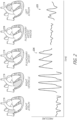
- FIG. 2 illustrates example pressure waveforms associated with various chambers and vessels of the heart according to one or more embodiments.
- the various waveforms illustrated in Figure 2 may represent waveforms obtained using right heart catheterization to advance one or more pressure sensors to the respective illustrated and labeled chambers or vessels of the heart.
- the waveform 225 which represents left atrial pressure, may be considered to provide the best feedback for early detection of congestive heart failure.
- Left atrial pressure may generally correlate well with left ventricular end-diastolic pressure.
- left atrial pressure and end-diastolic pulmonary artery pressure can have a significant correlation, such correlation may be weakened when the pulmonary vascular resistance becomes elevated. That is, pulmonary artery pressure generally fails to correlate adequately with left ventricular end-diastolic pressure in the presence of a variety of acute conditions, which may include certain patients with congestive heart failure.
- pulmonary hypertension which affects approximately 25% to 83% of patients with heart failure, can affect the reliability of pulmonary artery pressure measurement for estimating left-sided filling pressure.
- pulmonary artery pressure measurement alone may be an insufficient or inaccurate indicator of left ventricular end-diastolic pressure, particularly for patients with comorbidities, such as lung disease and/or thromboembolism.
- Left atrial pressure may further be correlated at least partially with the presence and/or degree of mitral regurgitation.
- Left atrial pressure readings may be relatively less likely to be distorted or affected by other conditions, such as respiratory conditions or the like, compared to the other pressure waveforms shown in Figure 2 .
- left atrial pressure may be significantly predictive of heart failure, such as up two weeks before manifestation of heart failure. For example, increases in left atrial pressure, and both diastolic and systolic heart failure, may occur weeks prior to hospitalization, and therefore knowledge of such increases may be used to predict the onset of congestive heart failure, such as acute debilitating symptoms of congestive heart failure.
- Cardiac pressure monitoring such as left atrial pressure monitoring, can provide a mechanism to guide administration of medication to treat and/or prevent congestive heart failure. Such treatments may advantageously reduce hospital readmissions and morbidity, as well as provide other benefits.
- An implanted pressure sensor in accordance with embodiments the present disclosure may be used to predict heart failure up two weeks or more before the manifestation of symptoms or markers of heart failure (e.g., dyspnea).
- certain prophylactic measures may be implemented, including medication intervention, such as modification to a patient's medication regimen, which may help prevent or reduce the effects of cardiac dysfunction.
- Direct pressure measurement in the left atrium can advantageously provide an accurate indicator of pressure buildup that may lead to heart failure or other complications.
- trends of atrial pressure elevation may be analyzed or used to determine or predict the onset of cardiac dysfunction, wherein drug or other therapy may be augmented to cause reduction in pressure and prevent or reduce further complications.
- FIG. 3 is a block diagram illustrating an implant device 300 comprising a shunt (or other type of implant) structure 320.
- the shunt structure 320 is physically integrated with and/or connected to a sensor device 310.
- the sensor device 310 may be, for example, a pressure sensor, or other type of sensor.
- the sensor 310 comprises a transducer 312, such as a pressure transducer, as well as certain control circuitry 314, which may be embodied in, for example, an application-specific integrated circuit (ASIC).
- ASIC application-specific integrated circuit
- the control circuitry 314 may be configured to process signals received from the transducer 312 and/or communicate signals associated therewith wirelessly through biological tissue using the antenna 318.
- the antenna 318 may comprise one or more coils or loops of conductive material, such as copper wire or the like.
- at least a portion of the transducer 312, control circuitry 314, and/or the antenna 318 are at least partially disposed or contained within a sensor housing 316, which may comprise any type of material, and may advantageously be at least partially hermetically sealed.
- the housing 316 may comprise glass or other rigid material in some embodiments, which may provide mechanical stability and/or protection for the components housed therein.
- the housing 316 is at least partially flexible.
- the housing may comprise polymer or other flexible structure/material, which may advantageously allow for folding, bending, or collapsing of the sensor 310 to allow for transportation thereof through a catheter or other introducing means.
- the transducer 312 may comprise any type of sensor means or mechanism.
- the transducer 312 may be a force-collector-type pressure sensor.
- the transducer 312 comprises a diaphragm, piston, bourdon tube, bellows, or other strain- or deflection-measuring component(s) to measure strain or deflection applied over an area/surface thereof.
- the transducer 312 may be associated with the housing 316, such that at least a portion thereof is contained within or attached to the housing 316.
- the term "associated with” is used herein according to its broad and ordinary meaning. With respect to sensor devices/components being “associated with" a stent or other implant structure, such terminology may refer to a sensor device or component being physically coupled, attached, or connected to, or integrated with, the implant structure.
- the transducer 312 comprises or is a component of a piezoresistive strain gauge, which may be configured to use a bonded or formed strain gauge to detect strain due to applied pressure, wherein resistance increases as pressure deforms the component/material.
- the transducer 312 may incorporate any type of material, including but not limited to silicon (e.g., monocrystalline), polysilicon thin film, bonded metal foil, thick film, silicon-on-sapphire, sputtered thin film, and/or the like.
- the transducer 312 comprises or is a component of a capacitive pressure sensor including a diaphragm and pressure cavity configured to form a variable capacitor to detect strain due to pressure applied to the diaphragm.
- the capacitance of the capacitive pressure sensor may generally decrease as pressure deforms the diaphragm.
- the diaphragm may comprise any material(s), including but not limited to metal, ceramic, silicon, and the like.
- the transducer 312 comprises or is a component of an electromagnetic pressure sensor, which may be configured to measures the displacement of a diaphragm by means of changes in inductance, linear variable displacement transducer (LVDT) functionality, Hall Effect, or eddy current sensing.
- LVDT linear variable displacement transducer
- the transducer 312 comprises or is a component of a piezoelectric strain sensor.
- a piezoelectric strain sensor may determine strain (e.g., pressure) on a sensing mechanism based on the piezoelectric effect in certain materials, such as quartz. This technology is commonly employed for the measurement of highly dynamic pressures.
- the transducer 312 comprises or is a component of a strain gauge.
- a strain gauge embodiment may comprise a pressure sensitive element on or associated with an exposed surface of the transducer 312.
- a metal strain gauge is adhered to the sensor surface, or a thin-film gauge may be applied on the sensor by sputtering or other technique.
- the measuring element or mechanism may comprise a diaphragm or metal foil.
- the transducer 312 may comprise any other type of sensor or pressure sensor, such as optical, potentiometric, resonant, thermal, ionization, or other types of strain or pressure sensors.
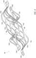
- FIG. 4 illustrates an example shunt structure 150 in accordance with one or more embodiments.
- the shunt structure 150 may represent an embodiment of a cardiac implant device that may be integrated with pressure sensor functionality in accordance with certain embodiments disclosed herein.
- the shunt structure 150 may be an expandable shunt. When expanded, a central flow channel 166 of the shunt 150 may define a generally circular or oval opening.
- the channel 166 may be configured to hold the sides of a puncture opening in a tissue wall to form a blood flow path between chamber(s) or vessel(s) of the heart that are separated by the tissue wall.
- the shunt 150 may be configured to be implanted in the wall separating the coronary sinus and the left atrium.
- the central flow channel 166 may be partly formed by a pair of side walls 170a, 170b defined by a generally parallelogram arrangement of thin struts 179 that forms an array of parallelogram-shaped cells or openings 180.
- substantially the entire shunt 150 is formed by super-elastic struts that are configured to be compressed and fit into a catheter (not shown) and subsequently expanded back to the relaxed shape as shown in Figure 4 .
- Formation of the shunt 150 using a plurality of interconnected struts forming cells therebetween may serve to at least partially increase the flexibility of the shunt, thereby enabling compression thereof and expansion at the implant site.
- the interconnected struts around the central flow channel 166 advantageously provide a cage having sufficient rigidity and structure to hold the tissue at the puncture in an open position.
- End walls 172a, 172b of the central flow channel 166 can serve to connect the side walls 170a, 170b and extend between distal and proximal flanges, or arms, 152, 154 on each side.
- the side walls 170a, 170b and end walls 172a, 172b together may define a tubular lattice, as shown.
- the end walls 172a, 172b can comprise thin struts 179 extending at a slight angle from a central flow axis of the shunt 150.
- the illustrated shunt 150 comprises struts that define a tubular or circular lattice of open cells forming the central flow channel 166
- the structure that makes up the channel forms a substantially contiguous wall surface through at least a portion of the channel 166.
- the tilt of the shunt structure 150 may facilitate collapse of the shunt into a delivery catheter (not shown), as well as the expansion of the flanges/arm 152, 154 on both sides of a target tissue wall.
- the central flow channel 166 may remain essentially unchanged between the collapsed and expanded states of the shunt 150, whereas the flanges/arms 152, 154 may transition in and out of alignment with the angled flow channel.
- shunt structures in accordance with the present disclosure have oval-shaped, rectangular, diamond-shaped, or elliptical flow channel configuration.
- relatively elongated side walls compared to the illustrated configuration of Figure 4 may produce a rectangular or oval-shaped flow channel.
- Such shapes of shunt flow channels may be desirable for larger punctures, while still being configured to collapse down to a relatively small delivery profile.
- each of the distal and proximal flanges/arms 152, 154 is configured to curl outward from the end walls 172a, 172b and be set to point approximately radially away from the central flow channel 166 in the expanded configuration.
- the expanded flanges/arms may serve to secure the shunt 150 to a target tissue wall.
- shunt structures or other implant devices integrated with pressure sensor functionality in accordance with embodiments the present disclosure may have any type, form, structure, configuration, and/or may be used or configured to be used for any purpose, whether for shunting or other purpose or functionality.
- FIG. 5 illustrates a sensor implant device 500 comprising a shunt structure 520 and an integrated sensor 510 in accordance with one or more embodiments.
- the sensor 510 may be built or manufactured into the shunt structure 520 to form a unitary structure.
- the sensor 510 may be attached to or integrated with an arm member 521 of the shunt structure 520.
- the sensor 510 includes a sensor element 512, such as a pressure sensor transducer.
- the transducer element 512 e.g., pressure transducer
- the illustrated embodiment of Figure 5 includes the transducer 512 disposed at the distal end 503 of the sensor 510.
- readings acquired by the sensor may be used to guide titration of medication for treatment of a patient in whom the implant device 520 is implanted.
- the senor 510 may be configured to implement wireless data and/or power transmission.
- the sensor 510 may include an antenna component 518 and control circuitry 514 configured to facilitate wireless data and/or power communication functionality.
- the antenna 518 comprises one or more conductive coils, which may facilitate inductive powering and/or data transmission.
- the sensor 510 may advantageously be biocompatible.
- the sensor 510 may comprise a biocompatible housing 516, such as a cylindrical or other-shaped housing comprising glass or other biocompatible material.
- the circuitry 514, sensor element 512, and/or antenna 518 may be at least partially contained within the housing 516, wherein the housing 516 is sealed to prevent exposure to such components to the external environment.
- the sensor element 512 such as a diaphragm or other component, may be exposed to the external environment in some embodiments in order to allow for pressure readings, or other parameter sensing, to be implemented.
- the housing 516 may comprise an at least partially rigid cylindrical or tube-like form, such as a glass cylinder form, wherein the sensing probe 512 is disposed at one or both ends 501, 503 of the sensor assembly 510.
- the sensor assembly is approximately 3 mm or less in diameter and/or approximately 20 mm or less in length.
- the sensor element 512 may comprise a pressure transducer, as described herein.
- the sensor assembly 510 may be configured to communicate with an external system when implanted in a heart or other area of a patient's body.
- the sensor 510 may receive power wirelessly from the external system and/or communicate sensed data or waveforms to and/or from the external system.
- the sensor assembly 510 may be attached to, or integrated with, the shunt structure 520 in any suitable or desirable way.
- the sensor 510 may be attached or integrated with the shunt structure 520 using mechanical attachment means.
- the sensor assembly 510 may be contained in a pouch or other receptacle that is attached to the shunt structure 520.
- the sensor element 512 may comprise a pressure transducer.
- the pressure transducer may be a microelectromechanical system (MEMS) transducer comprising a semiconductor diaphragm component.
- MEMS microelectromechanical system
- the transducer may include an at least partially flexible or compressible diaphragm component, which may be made from silicone or other flexible material.
- the diaphragm component may be configured to be flexed or compressed in response to changes in environmental pressure.
- the control circuitry 514 may be configured to process signals generated in response to said flexing/compression to provide pressure readings.
- the diaphragm component is associated with a biocompatible layer on the outside surface thereof, such as silicon nitride (e.g., doped silicon nitride) or the like.
- a biocompatible layer on the outside surface thereof, such as silicon nitride (e.g., doped silicon nitride) or the like.
- the diaphragm component and/or other components of the pressure transducer 512 may advantageously be fused or otherwise sealed to/with the housing 516 in order to provide hermetic sealing of at least some of the sensor assembly components.
- the control circuitry 514 may comprise one or more electronic application-specific integrated circuit (ASIC) chips or die, which may be programmed and/or customized or configured to perform monitoring functionality as described herein and/or facilitate transmission of sensor signals wirelessly.
- the antenna 518 may comprise a ferrite core wrapped with conductive material in the form of a plurality of coils (e.g., wire coil). In some embodiments, the coils comprise copper or other metal.
- the antenna 518 may advantageously be configured with coil geometry that does not result in substantial displacement or heating in the presence of magnetic resonance imaging.
- the sensor implant device 500 may be delivered to a target implant site using a delivery catheter (not shown), wherein the delivery catheter includes a cavity or channel configured to accommodate the advancement of the sensor assembly 510 therethrough.
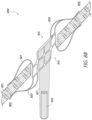
- Figure 6 illustrates a sensor implant device 600 having an integrated sensor 610 that is mechanically attached or fastened to a portion of a shunt structure 620.
- the shunt structure 620 comprises a sensor support 627, which may be a unitary form with this shunt structure 620.
- the support 627 is an extension of, or otherwise associated with, an arm member 621 of the shunt structure 620.
- the sensor 610 may be attached to the support 627 by any suitable or desirable attachment means, including adhesive attachment, or mechanical engagement.
- the sensor support 627 may comprise or be associated with one or more retention features 629, which may comprise one or more clamps, straps, ties, sutures, collars, clips, tabs, or the like.
- Such retention features 629 may circumferentially encase or retain the sensor 610, or a portion thereof.
- the sensor 610 may be attached to the sensor support 627 through the application of mechanical force, either through sliding the sensor 610 through the retention features 629 or through clipping, locking, or otherwise engaging the sensor 610 with the sensor support 627 by pressing or applying other mechanical force thereto.
- the retention features 629 comprise one or more tabs that may be configured to pop-up or extend on one or more sides of the sensor support 627 for mechanical fastening.
- Such tabs may comprise memory metal (e.g., Nitinol) or other at least partially rigid material.
- the sensor support 627 is at least partially non-rigid.
- the sensor support 627 may comprise a non-rigid tether configured to float the sensor 610. Such configurations may advantageously allow for the sensor 610 to move with the blood flow.
- the senor 610 is pre-attached to the sensor support 627 and/or integrated therewith prior to implantation.
- the sensor support 627 forms at least a portion of the housing of the sensor 610, such that the sensor support 627 and at least a portion of the housing of the sensor 610 are a unitary form.
- the angle or position of the sensor support 627 and/or sensor 610 relative to a longitudinal axis 601 of the shunt structure 620 is such that the sensor projects away from the longitudinal axis 601.
- the sensor 610 may advantageously project at least partially away from the biological tissue, such as into a chamber cavity (e.g., atrium of a heart).
- the sensor support 627 is configured, or can be configured, substantially at a right angle or 90° orientation with respect to the axis 601, such that the sensor is substantially orthogonal to the longitudinal axis of the shunt.
- Such configurations may advantageously allow for the sensor element to be positioned a desirable distance away from the shunted flow flowing through the flow path axis 603.
- the sensor element 612 of the sensor 610 may be disposed or positioned at any location of the sensor 610.
- the sensor element 612 may advantageously be disposed at or near a distal portion 607 of the sensor 610.
- a sensor element may be disposed or positioned at or near a proximal portion 605 of the sensor 610.
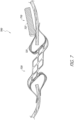
- Figure 7 illustrates a sensor implant device 700 having an integrated sensor 710 that is attached to a portion of a shunt structure 720 in accordance with one or more embodiments.
- the sensor 710 is attached to, or held within, a pouch 727 that is attached to or otherwise associated with an arm/flange member 721 or another portion of a shunt structure 720.
- the pouch 727 may be a suture-based or cloth-based pouch, wrapping, or other retention form.
- the sensor 710 is configured to be slidingly disposed within the pouch 727, wherein tension and/or compression of the pouch 727 serves to retain the sensor 710 in a fixed position within the pouch 727.
- the pouch 727 comprises a band or other non-enveloping retention means.
- the sensor 710 may be sutured or otherwise attached or fixed to the pouch 727.
- the pouch 727 may be sutured or otherwise fixed or attached to the arm member 721 of the shunt structure 720.
- embodiments of the present disclosure provide for a sensor attached to a flexible netting that is connected to at least a portion of a shunt structure such that the netting at least partially covers, or lies in, the flow path when deployed and allows flow through openings in the netting. Such embodiments may advantageously allow for deployment in accordance with Figures 8A-8D .
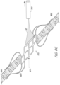
- Figure 8A shows a sensor implant device 800 in a delivery configuration within a delivery catheter 850.
- Figure 8A shows a shunt structure 820 of the sensor implant device 800 in a collapsed/delivery configuration within the catheter 850, wherein the shunt structure 820 is attached to a netting 827 that is in turn attached to or otherwise associated with a sensor 810.
- the sensor implant device 800 may be deployed within/from the catheter 850 and the direction shown, wherein the shunt structure 820 leads the sensor 810, which is pulled behind the shunt structure 820 by the tethered netting 827.
- the netting 827 may comprise braided memory metal (e.g., Nitinol), or other type of braid or mesh that is at least partially flexible.
- the netting advantageously has openings therein sufficiently large and configured to allow for the flow of fluid therethrough with relatively little or no obstruction or alteration of fluid flow through the flow path of the shunt structure 820.
- Figure 8B shows the shunt structure 820 in a deployed configuration and coupled to a biological tissue wall 801 via one or more arm members 821, as described herein.
- the sensor 810 has not yet been fully deployed, and trails the shunt structure 820 and is tethered thereto by the netting 827.
- the sensor 810 may be positioned on a proximal side 805 of the tissue wall 801, wherein it is desirable for the sensor to be deployed in a chamber or area associated with the distal side 802 of the tissue wall 801 when implanted.
- the netting 827 may be attached to the shunt structure 820 at a distal side 812 of the shunt structure, such as at a circumferential portion of a flow path channel defined by the shunt structure. Additionally or alternatively, the netting 827 may be coupled to the shunt structure 820 at or near a circumferential portion of a proximal side 815 of the shunt structure 820. In some embodiments, the netting 827 may be coupled to one or more arm members of the shunt structure 820.
- the senor 810 may be positioned in the coronary sinus, which may correspond to the proximal side 805 of the tissue wall 801, whereas the distal side 802 of the tissue wall may correspond to the left atrium.
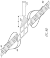
- Figure 8C shows the sensor 810 fully deployed on the distal side 802 of the tissue wall 801, which may be achieved by passing the sensor 810 through the flow path 876 of the shunt structure 820 and thereby introducing the sensor 810 into the chamber or area associated with the distal side 802 of the tissue wall 801, wherein the sensor 810 is at least partially captured by, or attached to, the netting, which tethers the sensor 810 to the shunt structure 820.
- the netting 827 may become at least partially inverted and/or folded, such that the sensor 810 exposed in the target area 802, as shown, whereas in the pre-deployed configuration shown in Figures 8A and 8B , the sensor was held within the netting 827.
- the sensor 810 may be captured or held within the netting 827 when in the deployed configuration shown in Figure 8C and attached outside the netting 827 in the pre-deployed configuration.
- Figure 8A shows the sensor 810 contained within that netting 827 in the pre-deployed configuration
- Figure 8C shows the sensor outside of the netting in the deployed configuration
- the sensor is initially attached outside the netting 827 in the pre-deployed configuration of Figure 8A
- the sensor may be drawn into the netting, such that it is substantially enclosed therein.
- the sensor 810 may be attached or fixed to the netting 827 using any suitable or desirable attachment means or mechanism. By inverting the netting 827, as shown in Figure 8C , the sensor 810 may be projected into the left atrium, or other chamber.
- Figure 8D shows the deployed sensor implant device 800 and a retracted state, wherein the netting 827 has been cinched or retracted to some degree in order to reduce the distance ⁇ d' and/or position of the sensor 810 relative to the shunt structure 820.
- the netting 827 may comprise memory metal, or other material that may be manipulated or formed to a suitable or desirable form in response to a certain stimulus or force, such as the cinched form of Figure 8D .
- the netting 827 may advantageously comprise weaved or braided memory metal (e.g., Nitinol) that has flexibility and/or elasticity characteristics that allow for the sensor to pull the netting at least partially through the flow path 876 of the shunt structure 820.
- the netting 827 comprises re-flowed Carbothane, or polyurethane.
- the netting is laser bonded.
- the netting comprises holes sufficiently large to reduce the risk of clogging.
- Sensor-integrated shunt implant devices in accordance with embodiments of the present disclosure may be implanted in any suitable or desirable tissue wall.
- a sensor-integrated shunt device in accordance with embodiments of the present disclosure is implanted in the interatrial septal wall.
- embodiments of the present disclosure may comprise any type of cardiac shunt or implant device implanted in any location of the heart or body and incorporating any type of telemetric monitoring functionality.
- Figures 9 shows a sensor implant device 900 implanted in an atrial septum 18 in accordance with one or more embodiments.
- the particular position in the interatrial septum wall may be selected or determined in order to provide a relatively secure anchor location for the shunt structure 920, as well as to provide a relatively low risk of thrombus.
- the sensor implant device 900 may be implanted at a position that is desirable in consideration of future re-crossing of the septal wall for future interventions. Implantation of the sensor implant device 900 in the interatrial septum wall may advantageously allow for communication between the left 2 and right 5 atria.
- the sensor 910 of the sensor implant device 900 may advantageously be configured to measure pressure in the right atrium 5, the left atrium 2, or both atria.
- the device 900 comprises a plurality of sensors, wherein one sensor is disposed in each of the right atrium 5 and the left atrium 2.
- the sensor implant device 900 may advantageously be configured to provide sensor signals that may be used to determine differential pressure between the atria. Differential pressure determination may be useful for monitoring fluid build-up in the lungs, which may be associated with congestive heart failure.
- Interatrial shunting using the sensor implant device 900 may advantageously be well-suited for patients that are relatively highly sensitive to atrial pressure increases.
- the muscles of the heart may generally be prone to contract relatively harder according to process the excess blood. Therefore, as the ventricle dilates or stretches, for patients with compromised contractility of the ventricle, such patients may become more sensitive to higher pressures in the ventricle and/or atria because the heart may be unable to adequately respond or react thereto.
- left atrial pressure can results in dyspnea, and therefore reduction in left atrial pressure to reduce dyspnea and/or reduce incidences of hospital readmission may be desirable through interatrial shunting.
- the ventricle experiences dysfunction such that is unable to accommodate build-up in fluid pressure, such fluid may backup into the atria, thereby increasing atrial pressure.
- minimization of left ventricular end-diastolic pressure may be paramount. Because left ventricular end-diastolic pressure can be related to left atrial pressure, backup of fluid in the atrium can cause backup of fluid in the lungs, thereby causing undesirable and/or dangerous fluid buildup in the lungs.
- Interatrial shunting such as using shunt devices in accordance with embodiments of the present disclosure, can divert extra fluid in the left atrium to the right atrium, which may be able to accommodate the additional fluid due to the relatively high compliance in the right atrium.
- interatrial shunting may not be sufficiently effective due to the patient being subject to a drug regimen designed to control the patient's fluid output and/or pressure.
- diuretic medications may be used to cause the patient to expel excess fluid. Therefore, use of pressure-sensor-integrated implants in accordance with embodiments the present disclosure may provide a mechanism to inform technicians or doctors/surgeons with respect to how to titrate such medications to adjust/modify fluid status. Therefore, embodiments the present disclosure may advantageously serve to direct medication intervention to reduce or prevent& the undesirable increase in left atrial pressure.
- sensor-integrated shunt implant devices in accordance with embodiments of the present disclosure may be implanted in the wall separating the coronary sinus from the left atrium.
- interatrial shunting may be achieved through the coronary sinus.
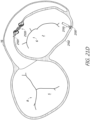
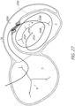
- Figure 10 shows a sensor implant device 100 implanted in a tissue wall 103 between the coronary sinus 16 and the left atrium 2.
- Figure 10 shows a section of the heart from a top-down perspective with the posterior aspect oriented at the top of the page.
- Interatrial shunting through implantation of the shunt device 100 in the wall 103 between the left atrium 2 and the coronary sinus 16 can be preferable to shunting through the interatrial septum 101 in some situations.
- shunting through the coronary sinus 16 can provide reduced risk of thrombus and embolism.
- the coronary sinus is less likely to have thrombus/emboli present for several reasons.
- First, the blood draining from the coronary vasculature into the right atrium has just passed through capillaries, so it is essentially filtered blood.
- the ostium of the coronary sinus in the right atrium is often partially covered by a pseudo-valve called the Thebesian Valve.
- Thebesian Valve is not always present, but some studies show it is present in most hearts and can block thrombus or other emboli from entering in the event of a spike in right atrium pressure.
- the pressure gradient between the coronary sinus and the right atrium into which it drains is generally relatively low, such that thrombus or other emboli in the right atrium is likely to remain there.
- thrombus/emboli do enter the coronary sinus, there will be a much greater gradient between the right atrium and the coronary vasculature than between the right atrium and the left atrium. Most likely, thrombus/emboli would travel further down the coronary vasculature until right atrium pressure returned to normal and then the emboli would return directly to the right atrium.
- shunt structure 120 between the left atrium and the coronary sinus is that this anatomy is generally more stable than the interatrial septal tissue. By diverting left atrial blood into the coronary sinus, sinus pressures may increase by a small amount. This would cause blood in the coronary vasculature to travel more slowly through the heart, increasing perfusion and oxygen transfer, which would be more efficient and also could help a dying heart muscle to recover.
- the shunt device 100 by implanting the shunt device 100 in the wall of the coronary sinus 103, damage to the interatrial septum 101 may be prevented. Therefore, the interatrial septum may be preserved for later transseptal access for alternate therapies.
- the preservation of transseptal access may be advantageous for various reasons. For example, heart failure patients often have a number of other comorbidities, such as atrial fibrillation and/or mitral regurgitation; certain therapies for treating these conditions require a transseptal access.
- Access to the target wall 103 and left atrium 2 via the coronary sinus 16 may be achieved using any suitable or desirable procedure.
- various access pathways may be utilized in maneuvering guidewires and catheters in and around the heart to deploy an expandable shunt integrated or associated with a pressure sensor in accordance with embodiments of the present disclosure.
- access may be achieved through the subclavian or jugular veins into the superior vena cava (not shown), right atrium 5 and from there into the coronary sinus 16.
- the access path may start in the femoral vein and through the inferior vena cava (not shown) into the heart.
- Other access routes may also be used, each of which may typically utilize a percutaneous incision through which the guidewire and catheter are inserted into the vasculature, normally through a sealed introducer, and from there the system may be designed or configured to allow the physician to control the distal ends of the devices from outside the body.
- a guidewire is introduced through the subclavian or jugular vein, through the superior vena cava and into the coronary sinus.
- an introducer sheath may be routed along the guidewire and into the patient's vasculature, typically with the use of a dilator.
- the delivery catheter may be advanced through the superior vena cava to the coronary sinus of the heart, wherein the introducer sheath may provide a hemostatic valve to prevent blood loss.
- a deployment catheter may function to form and prepare an opening in the wall of the left atrium, and a separate placement or delivery catheter will be used for delivery of an expandable shunt.
- the deployment catheter may be used as the both the puncture preparation and implant delivery catheter with full functionality.
- deployment catheter or “delivery catheter” are used to represent a catheter or introducer with one or both of these functions.
- the coronary sinus is generally contiguous around the left atrium 2, and therefore there are a variety of possible acceptable placements for the implant device 100 and/or shunt structure 120.
- the target site selected for placement of the shunt structure 120 may be made in an area where the tissue of the particular patient is less thick or less dense, as determined beforehand by non-invasive diagnostic means, such as a CT scan or radiographic technique, such as fluoroscopy or intravascular coronary echo (IVUS).
- non-invasive diagnostic means such as a CT scan or radiographic technique, such as fluoroscopy or intravascular coronary echo (IVUS).
- Sensor components of sensor-functionality-integrated shunt implant devices in accordance with embodiments of the present disclosure may have any suitable or desirable configuration.
- sensors in accordance with embodiments of the present disclosure may comprise an antenna that is tethered in some manner to sensor circuitry and/or shunt or implant structure.
- the profile of the sensor implant device may be undesirably large, such that delivery of the device to the target location through transcatheter access may be difficult or untenable.
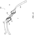
- FIG. 11 illustrates a sensor implant device 200 comprising a tethered antenna 218, which may advantageously have relatively small profile for transcatheter delivery.
- the antenna 218 is advantageously electrically coupled to a senor element 212, such as a pressure transducer and/or associated control circuitry.
- the sensor element 212 which may comprise one or more of the transducer and/or control circuitry (e.g., application-specific integrated circuit) of the sensor may be attached or otherwise integrated onto an arm 221 of the shunt structure 220.
- the sensing element 212 may be attached to shunt structure that is disposed at least partially within the left atrium 2, as shown.
- the sensing element 212 is shown as attached or integrated with the arm 221, it should be understood that the sensor element 212 may be attached to any other arm or flange of the shunt structure 220, or to any other portion or feature of the shunt structure 220, such as within the flow path of the shunt structure 220.
- the antenna associated with the sensing element 212 may be positioned or disposed in a different area or region of the heart anatomy or shunt structure 220.
- the antenna 218 may be tethered to the shunt structure 220 and/or sensing element 212 via an electrical coupling tether 227.
- the tether 227 may serve to both physically couple the antenna to the device 200 to maintain the antenna 218 in a certain position and/or within a certain distance or orientation with respect to the shunt structure 220, and may further serve to provide electrical signal transmission between the antenna 218 and the sensing element 212.
- the sensing elements 212 may be configured to generate electrical signals indicative of, or relating to, pressure in at least a portion of the left atrium 2, wherein such signals may be transmitted via the tether 227 to the antenna 218, which may wirelessly transmit the signals.
- the antenna 218 is configured to receive power inductively from an external power source through biological tissue separating the device 200 from the external system.
- the antenna 218 may comprise any suitable or desirable conductive material and/or configuration that is compatible with the relevant anatomy and/or procedure.
- the antenna 218 comprises a plurality of coils that are hermetically sealed to provide biocompatibility.
- the sensor implant device 200 may advantageously provide a reduced effect or obstruction at or near the area of the shunt structure 220 relative to certain other sensor implant devices disclosed herein.
- a delivery catheter used to deliver the device 200 to the target location may be modified to have a cavity that accommodates the presence of the antenna 218 therein.
- the antenna 218 may be tethered to the device 200 in any other location or position.
- the antenna may be disposed or positioned in the left atrium 2 when deployed and tethered to the device 200.
- the tether 227 may be sufficiently long to allow for the antenna 218 to be disposed within the right atrium (not shown) when the shunt structure 220 is implanted in the wall separating the coronary sinus from the left atrium. Placement or maintenance of the antenna 218 in the right atrium rather than the coronary sinus 16 may be preferable due to the relatively greater volume of space available to the antenna 218 in the right atrium.
- the antenna 218 represents the largest component of the sensor implant device 200 with respect to at least one dimension thereof. In some implementations, the antenna 218 is configured to be disposed in an area of the coronary sinus that is relatively wide or large (e.g., having a relatively large cross-sectional area). In some embodiments, the antenna 218 is encased in glass, polymer, or other biocompatible material.
- the tether 227 may comprise an insulated wire.
- the tether is at least partially rigid or stiff, such that the geometry and/or positioning of the antenna 218 may not readily change in response to cardiac cycles. For example, where the antenna 218 is permitted to move and/or shift freely are readily, such movement affect the frequency of transmitted signals, which may result in signal transmission error.
- the device 200 comprises matching circuitry configured to account for or cancel out signal noise due to movement of the antenna 218.
- the antenna 218 of the sensor implant device 200 may be used to power the sensing element 212 and/or transmit data from the device 200 to an external system (not shown).
- the antenna of a sensor implant device has a flat shape or form when deployed.
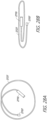
- the antenna may comprise winds of conductor in a spiral inductor configuration/geometry, as shown in Figure 12A .
- the flat spiral antenna 1218 of Figure 12A may be sealed in a biocompatible tape or membrane, such as polydimethylsiloxane or another biocompatible elastomer.
- the flat antenna 1218 may advantageously be at least partially flexible to allow for folding, rolling, or compression thereof for fitting within a delivery catheter as described herein.
- Figure 12B shows the flat spiral antenna 1218 in a rolled or folded delivery configuration, which may provide a relatively smaller profile with respect to one or more dimensions of the antenna 1218.
- the flat antenna 1218 may be sutured to a wall of an atrium or coronary sinus or may be freely disposed in, or wedged or positioned in, an atrium or coronary sinus.
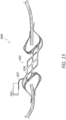
- a sensor implant device 1300 may comprise a shunt structure 1320 including one or more arms 1321 and a flow path conduit or barrel portion 1322.
- a shunt structure 1320 including one or more arms 1321 and a flow path conduit or barrel portion 1322.
- the term "conduit” is used according to its broad and ordinary meaning, and may refer to any channel, duct, aperture, canal, pipe, tube, or similar structure, whether solid or having openings or mesh-type form.
- the pressure sensor element 1312 may comprise a pressure transducer configured to convert environmental pressure into electrical signals.
- the sensor element 1312 may further be integrated with control circuitry for processing and/or transforming pressure-based signals.
- the sensor elements 1312 is illustrated as being attached to or integrated with an arm member 1321 of the sensor implant device 1300, it should be understood that the sensor element 1312 may be attached to or associated with any portion or member, or feature of the shunt structure 1320, as described in detail herein.
- the antenna 1318 may comprise a conductive wire or wire loops that is/are insulated in some manner.
- the antenna 3018 may comprise wire incorporated in an insulated preformed tape, or other flexible insulating membrane.
- the antenna 1318 may be used to wirelessly communicate with an external system when the sensor implant device 1300 is implanted in the patient.
- the antenna 1318 may be configured to receive inductive power transfer from an external system, as described herein.
- the sensor implant device 1300 may be delivered in a collapsed state, wherein the shunt structure is at least partially collapsed, as described herein.
- the antenna 1318 may be incorporated in a carrier tape or other membrane that is configured to fold and be delivered within the catheter.
- the antenna may also be designed or configured to expand to assume a deployed state.
- the sensor element 1312 is attached to or integrated with an arm member 1321, which extends generally along a longitudinal dimension or axis 1301 of the shunt structure 1320.
- a sensor implant device 1400 including an antenna 1418 wrapped around a flow path structure or conduit 1322 may be coupled to a sensor element 1412 that extends away from the antenna along a dimension parallel to the flow path axis 1402.
- the sensor element 1412 may be connected to the antenna 1418 via a conductor 1427 that extends generally parallel with the flow path axis, such that the sensor element 1412 is disposed within or near the flow path 1402 of fluid through the shunt.
- the sensor element 1412 may be coupled to the antenna 1418 via a shape-set conductor 1428 configured to hold or maintain the sensor element 1412 away from the flow path of the shunt, as shown.
- a sensor implant device 1500 may comprise a shunt structure 1520 coupled to a sensor element 1512 via a connector 1527.
- the shunt structure may be metal or comprise other conductive materials.
- the shunt structure 1518 comprises conductive material, such as memory metal (e.g. Nitinol), wherein the shunt structure 1518 also serve as an antenna for data and/or power transmission in accordance with principles disclosed herein.
- the sensor element 1512 may comprise a pressure sensor.
- the connector 1527 comprises an at least partially rigid wire or structure configured to allow for the transmission of electrical signals, such as electrical signals indicating pressure readings obtained by the sensor element 1512, from the sensor element 1512 to the antenna shunt body 1518.
- the antenna shunt structure 1518 can transmit such signals wirelessly for reception external to the patient in whom the sensor implant device 1500 is implanted.
- the conductive shunt body 1518 of the implant device 1500 may further serve to receive wireless power from an external power source through biological tissue of the patient.
- at least a portion of the shunt structure 1518 is coated with an insulating material and/or a conductive material, such as gold.
- the conductive shunt structure 1518 may comprise titanium.
- certain shunt structure/form is illustrated Figure 15 , it should be understood that the conductive shunt structure 1518 may have any form or shape.
- the flow path conduit or barrel portion 1522 of the shunt structure 1518 has a coil-/spring-type shape, wherein arm members of the device are attached to the barrel/conduit portion and electrically isolated therefrom in some manner.
- the coil/spring shape of the barrel/conduit portion may serve as an inductive antenna and may function according to principles and embodiments disclosed herein with respect to wireless data and/or power transfer.
- the present disclosure provides sensor implant devices having a sensor attached to a shunt structure such that the sensor lies at least partially in the flow path of the shunt structure.
- Figure 16A-16C illustrate a sensor implant device 1600 having a sensor 1610 integrated therewith, such as a pressure sensor as described herein.
- the sensor 1610 is attached to, or otherwise integrated with, a flow path barrel or conduit portion 1622 of a shunt structure 1620, such that the sensor 1610 is disposed within or near the flow path channel associated with the barrel/conduit 1622.
- Figure 16A is a perspective view of the sensor implant device 1600.
- the sensor 1610 has an elongate cylindrical shape.
- the sensor 1610 includes a first sensor element 1612 at a first end of the sensor 1610 that is disposed on a first side 1616 of a tissue wall 1601 and the shunt structures 1620 when implanted in a patient, such as in a wall separating the coronary sinus from the left atrium.
- the sensor 1612 may be positioned to be exposed within the left atrium, which may be represented by the side or region 1616 in the illustrated diagram.
- the sensor 1610 may further comprise a second sensor 1613 disposed on an opposite side of the sensor 1610.
- the sensor 1613 may be configured and positioned to be exposed in a chamber or area associated with an opposite side of the tissue wall 1601 and/or shunt structure 1620, such as within the coronary sinus.
- the sensor elements 1612, 1613 may be disposed or positioned in perspective atria, wherein one sensor element provides pressure readings associate with the left atrium and the other provides pressure readings associate with the right atrium, as described in detail above. Using two sensor elements as shown in Figure 16A may allow for measurement of differential pressure drop across the shunt structure 1620.
- the shunt structure 1620 With the sensor 1610 disposed or attached in or near the flow path channel of the shunt structure 1620, the sensor 1610 may be configured to provide sensor readings that can be used to indirectly measure flow across or through the shunt structures 1620 based at least in part on fluid momentum associated with fluid contacting the sensor element(s). Furthermore, the sensor(s) may generate readings relating to velocity of flow through the shunt, wherein such readings may be used to determine or indicate undesirable occlusion or closing-off of the shunt flow path. In certain embodiments, pressure waveforms generated using the sensor(s) may be used to generate and/or maintain a waveform profile relating to the pressure readings.
- Changes in the pressure reading profile may indicate health complications and may therefore be used to trigger alerts or notifications, which may be relied upon to alter drug or other therapies.
- the pressure readings from the sensor(s) are analyzed to determine average, diastolic, and/or systolic pressure data points.
- the shunt structure 1620 is mounted or attached at or near the orifice or channel of the shunt structure 1620, rather than to one or more arm members, as described above.
- the sensor 1610 may be built into, or otherwise integrated with, the shunt structure 1620, or may be otherwise attached or associated therewith.
- Figures 16A-16C illustrate the sensor 1610 attached or integrated with the barrel/conduit portion 1622 of the shunt structure 1620 on an outside surface thereof, it should be understood that in some embodiments the sensor 1610 may be disposed, attached, or otherwise integrated with the barrel/conduit portion 1622 on an inside surface thereof.
- the senor 1610 may fit within a pocket/receptacle feature 1625 of the barrel/conduit 1622.
- the sensor 1610 comprises or is associated with one or more projections 1627 configured or designed to hold or secure the sensor 1610 to the shunt structure 1620.
- Figure 16B shows a front view of the sensor implant device 1600 in accordance with one or more embodiments.
- Figure 16B shows the sensor 1610 nested in a pocket/receptacle feature 1625 associated with the barrel portion 1622 of the shunt structure 1620.
- Figure 16C shows a bottom or top view of the sensor implant device 1600, showing the sensor 1610 disposed in the flow path 1603 of the shunt structure.
- the sensor 1610 is sutured to the shunt structure.
- the sensor 1610 is held within a sock or pouch that is sutured or otherwise attached to the shunt structure 1620.
- a pressure sensor device may be implanted through the wall separating the left atrium from the coronary sinus.
- Figure 17 shows a sensor device 1710 implanted in the wall 1701 separating left atrium 2 from the coronary sinus 16.
- the sensor device 7010 may be implanted in the tissue 1701 as part of the procedure to implant a shunt structure 1720 in the same wall or area as the sensor device 7010, as shown.
- the sensor device 1710 may be carried in the same delivery catheter used to deliver the shunt structure 1720 or may be delivered using a separate catheter.
- the sensor 1710 is deployed in the same procedure in which the shunt structure 7020 is deployed.
- FIGs 18A-18C illustrate deployment from a delivery catheter 1760 of a sensor device 1710 configured to be implanted in a tissue wall in accordance with one or more embodiments.
- the sensor device 1710 may include certain wall anchor features 1770.
- the anchor feature(s) 1770 may be in a straightened or extended configuration, as shown in Figure 8A .
- the tissue anchor feature 1770 may be configured to extend outward and provide compressive force on a target tissue wall, such as the wall separating left atrium from the coronary sinus.
- the sensor device 1710 includes a sensor element at each end of the sensor, namely the sensor element 1712 and the sensor element 7013.
- the sensor device 1710 may be deployed from the delivery catheter 1760 using a pusher device 1762, as shown in Figure 18B .
- the anchor feature(s) 1770 may be used to anchor the sensor device 1710 adjacent to and/or near an implanted shunt structure, as shown in Figure 17 .
- the sensor device of 1710 may be configured to detect pressure readings that may be used to determine pressure differentials between the left atrium and the coronary sinus. Because pressure in the coronary sinus may be related to pressure in the right atrium, readings of pressure on the sensor element disposed in the coronary sinus may be used to determine sensor measurements relating to right atrial pressure. With the orientation and disposition shown in Figure 17 , the sensor elements 1712 and 1713 may have little or no flow passing by the sensor elements, such that the pressure readings associated therewith are not substantially influenced by flow velocity.
- the sensor device 7010 may be deployed with the aid of a guide wire 1780, which may be delivered to the right atrium through the inferior vena cava or superior vena cava, and further through the coronary sinus to the target delivery site.
- Access to the right atrium may be via jugular or femoral access.
- jugular access access to the right atrium may be via the superior vena cava, whereas procedures involving femoral access may provide access to the right atrium via the inferior vena cava.
- the distal tip of the sensor 1710 comprises or is connected to a screw point or other tissue piercing feature (not shown) that may be used to drive the sensor 1710 through the tissue wall separating the left atrium 2 from the coronary sinus 16.
- tissue-piercing functionality may reduce or obviate the need for tissue dilation or piercing separately for the sensor 1710.
- the sensor 1710 may further comprise a jacket or covering made with lubricious anti-thrombus-forming material. Such covering may be used to house the guide wire 1780 and/or anchor features 1770.
- Figure 19 illustrates a sensor implant device 1900 including a stent structure 190, which is integrated with or attached to a sensor 191, as shown.
- the stent structure 190 may advantageously be implemented in the coronary sinus, wherein at least a portion of the sensor implant device 1900 is configured to pass through the wall between the left atrium 2 and the coronary sinus 16.
- the sensor 191 is mounted to the stent structure 190 using any suitable or desirable mounting or attachment means or mechanism, including a clip, tab, suture, screw, or other anchor or attachment means or mechanism.
- the stent structure 190 may serve to anchor the sensor 191 in the coronary sinus.
- the stent structure 190 is configured to be positioned or configured such that it is secured relative to the stent structure 190 at an angle, as illustrated.
- the sensor is positioned at a substantially right angle with respect to a longitudinal axis 199 of the stent structure 190, such that the sensor 191 Jets out into the left atrium 2.
- the stent structure 190 may advantageously provide a relatively solid anchoring point for the sensor 191, such that the sensor 191 does not move substantially after implantation thereof and disposition in the left atrium 2.
- Figure 20 illustrates a sensor implant device 299 including two sensors 291, 292, which may be pressure sensors or other types of sensors.
- the sensors are configured to be implanted on opposite sides of the tissue wall 290.
- the sensors 291, 292 may be implanted and positioned on opposite sides of the wall separating the left atrium from the coronary sinus, as described in detail herein.
- the sensors 291, 292 may be secured to one another by an attachment means 297, which may comprise one or more rigid and/or flexible members, such as a strap, bar, suture, arm, or the like.
- the attachment member 297 may be configured to be tightened to a desirable tension between the sensors 291, 92, such that the sensors are secured and held against the tissue wall 290.
- Each of the sensors 291, 292 may be configured to measure a physiological parameter, such as fluid pressure, or any other parameter, in its respective chamber or area of implantation.
- the sensor 291 may be configured to measure one or more parameters associated with the chamber or area 295 on one side of the tissue wall 290, whereas the sensor 290 to may be configured to measure one or more parameters on the opposite side 296 of the tissue wall 290, as shown.
- the implant device 299 may provide for differential parameter (e.g., pressure) measurements and/or other differential or comparative parameter analysis.
- FIGS 21A-21D illustrate stages of a process for implanting a pressure sensor or other type of sensor in an atrium or other region of the heart.
- Figure 21A shows a guidewire 2180 that has been introduced to the left atrium 2 of the heart through a coronary sinus access opening 2103 in a wall 2101 separating the left atrium 2 from the coronary sinus 16.
- the guidewire 2180 may have been introduced into the left atrium 2 in connection with a procedure for implanting a shunt structure 2120 in the wall 2101 to provide shunting between the left atrium 2 and the coronary sinus 16. That is, when implanting the shunt structure 2120, the procedure may involve advancing the guidewire further through the opening 2103 to a location within the left atrium 2 where a sensor device is desired to be implanted.
- the process may involve advancing a delivery catheter 2160 over the guidewire 2180, the delivery catheter 2160 carrying a sensor device.
- the delivery catheter 2160 may be a different catheter than was used to deliver the implanted shunt structure 2120 or may be the same catheter used to deliver the shunt structure 2120.
- the delivery catheter comprises a distal end portion 2161 having a rapid-exchange slot or feature 2163, which may be configured to engage the guidewire 2180, such that the delivery catheter 2160 may be guided or advanced along the path defined by the guidewire 2180.
- the guidewire slot or engagement feature 2163 can be used to transition the guidewire 2180 to the delivery catheter system 2160.
- the slot or engagement feature 2163 may provide a side-running guide for advancement of the delivery catheter 2160.
- the use of a side-running guidewire engagement feature, as shown in Figure 21A may advantageously allow for the delivery of a solid-body sensor device 2110 within a lumen or cavity of the delivery catheter 2160, such as at least partially within the end portion 2161.
- Figure 21B shows the delivery catheter 2160, and in particular the distal end portion 2161, advanced to the target sensor implantation site at a wall portion 2102 of the atrium 2.
- the sensor 2110 (see Figure 21C ) may be implanted using tissue anchor features 2197 that may be attached to or integrated with the sensor 2110. Therefore, as shown in Figure 21B , by applying force with the delivery catheter 2160 to puncture or engage the anchor features 2197 in the tissue 2102, the anchor features 2197 may become embedded or secured into the tissue 2102.
- the process may involve releasing the sensor 2110 from the delivery catheter 2160 and/or distal end portion 2161.
- the delivery catheter 2160 may then be withdrawn from the cardiac anatomy, leaving the sensor 2110 implanted at the target location, as well as the shunt structure 2120 in its separate implantation location, as shown in Figure 21D . Therefore, the process illustrated in Figures 21A-21D may allow for implantation of a shunt structure and a separate pressure sensor at separate locations of an atrium or other cardiac region using a single guidewire and atrium access opening, which may reduce risks of damage to the cardiac anatomy and/or provide a more efficient mechanism for implantation of such devices.
- a sensor device may be docked on a shunt structure or other implant device, such that the sensor device is secured in a desired location to provide sensor readings.
- a shunt structure may be implanted in cardiac tissue, after which a sensor may be docked on the shunting structure as part of the same procedure.
- Figures 22 and 23 illustrates a process for docking a sensor device 2210 on a shunt structure 2220 in accordance with one or more embodiments.
- embodiments of the present disclosure may involve implanting a shunt structure 2220 in tissue 2201 of a heart, such as in a wall separating the left atrium 2 from the coronary sinus 16, as well as a sensor device 2210 comprising a transducer or sensor element 2212.
- the shunt structure 2220 may be attached to the distal end of a guidewire 2280 prior to implantation of the shunt structure 2220.
- the guidewire 2220 may be placed initially within the atrium 2.
- the shunt structure 2220 may be implanted in the tissue wall 2201, after which withdrawal of the guidewire may cause the sensor 2210 to become engaged in the anchor features 2227, as shown in Figure 23 .
- the engagement between the sensor device 2210 and the anchor features 2227 may comprise a compression-fit or snap mechanism, or the like.
- the sensor 2210 may be configured to attach to the anchor features 2227 via a coupling feature 2228 of any suitable or desirable size, shape, form, or configuration.
- the process may involve advancing the guidewire 2280 through an access 2203 in the tissue wall 2201 in connection with implantation of the shunt structure 2220.
- the guidewire 2280 may be advanced into the left atrium 2 past the anchor feature(s) 2227 associated with the shunt structure 2220.
- the anchor features 2227 may be associated with (e.g., integrated with or attached to) an arm portion or other portion of the shunt structure 2220.
- the guidewire 2280 may allow for simplified location of the access 2203, such that the delivery catheter may be relatively easily advanced along the guidewire into the atrium 2 or another target location.
- the process may further involve subsequently advancing the delivery catheter including a sensor device 2210 having at least one sensor element 2212 into the target chamber (e.g., left atrium).
- the sensor 2210 may advantageously be advanced past the anchor features 2227, wherein the sensor device 2210 may be anchored into the anchor features 2227 by pulling back on the sensor to clamp or fix the sensor device 2210 in engagement with the anchor features 2227, as shown in Figure 23 .
- the sensor device 2210 is attached to or integrated with corresponding mating features for engaging with the anchor features 2227.
- the procedure illustrated in Figures 22 and 23 may provide significant time savings by not requiring the guidewire 2280 to be withdrawn and/or replacing with a subsequent guidewire. Such time and resource savings may be particularly relevant with respect to access to the left atrium to the coronary sinus 16, as shown and described herein.
- the guidewire 2280 may attach mechanically to the sensor 2210.
- a coupling feature 2228 associated with a sensor device 2210 may serve to attach the sensor device 2010 guidewire 2280.
- FIG. 24 illustrates a shunt structure 2420 having a sensor attachment rack feature 2471.
- the attachment rack 2471 comprises a plurality of teeth, protrusions, gears, or other engagement features for mating with corresponding features associated with a sensor device.
- Figure 25 shows a sensor device 2410 including an attachment rack feature 2473 including a plurality of teeth 2474, which may be configured and/or dimensioned to engage with the corresponding teeth 2472 of the shunt structure 2420.
- Figure 26 illustrates a process for attaching the sensor device 2410 of Figure 25 to the shunt structure 2420 of Figure 24 described above.
- a guidewire 2480 may be advanced to the left atrium or other target chamber, vessel, or location.
- the guidewire 2480 may be used to implant the shunt structure 2420 in a tissue wall 2401 of the atrium, such as a wall separating the left atrium 2 from the coronary sinus 16.
- the guidewire 2480 With the shunt structure positioned as shown in Figure 26 , the guidewire 2480 may be left in place, and may be used to hold open or otherwise interfere in some manner with the rack attachment feature 2472 of the shunt structure.
- the guidewire 2480 may further be used to deliver the sensor device 2410, including the engagement/attachment feature 2473 to the location where the shunt structure 2420 is implanted.
- the guidewire 2480 may subsequently be removed, allowing the mating teeth of the shunt structure 2420 and the sense device 2410 to engage or snap into locking engagement with one another to thereby secure the sensor device 2410 to the shunt structure 2420.
- use of the guidewire 2480 or interfere with the mating between the shunt structure 2420 and the sensor device 2410 is described, in some embodiments no such guidewire interference is implemented.
- the sensor device 2410 may simply be advanced to the location of the shunt structure 2420 and pressure applied to engage the attachment features 2473 of the sensor device one 410 with the corresponding features 2471 of the shunt structure 2420.
- a sensor device such as a pressure sensor device, may be implanted in atrium or other chamber of the heart using one or more radially-expanding anchor features or coils.
- Figure 27 illustrates a sensor device 2710 suspended in the left atrium 2 of the heart. Although certain embodiments are disclosed herein context of the left atrium, it should be understood that sensors in accordance with the present disclosure may be implanted in the right atrium or other chamber of the heart or body.
- the sensor 2710 is mounted or attached to a relatively large radially-expanding anchor system comprising a radially expanding wire 2727.
- the wire 2727 may be configured to contact at least a portion of the inner wall of the atrium 2 when expanded.
- the wire 2727 is configured to exert outward radial force against the walls of the atrium to thereby suspend the sensor device 2710 in a central portion of the atrium.
- the wire 2727 may be at least partially flexible/elastic to allow for contracting and/or expanding in response to contraction and expansion of the atrium in connection with cardiac cycles.
- a shunt structure in accordance with embodiments the present disclosure may be implanted in the wall of the atrium 2, such as in the walls of the left atrium from the coronary sinus, in the same procedure used to dispose the sensor device 2710 in the atrium 2.
- the process for implanting the sensor device 2710 in the atrium 2 may involve accessing the atrium through the coronary sinus 16, as described in connection with other embodiments described herein. Access to the left atrium 2 may be made via a hole or opening in the wall 2701 separating the left atrium 2 from the coronary sinus 16.
- the sensor device 2710 and associated anchor wire 2727 may be delivered to the atrium to using a guidewire 2780, which may be attached to or integrated with the anchor wire 2727.
- a detachable joint feature 2728 may allow for detachment of the anchor wire 2727 from the guidewire 2780 after deployment thereof.
- Figure 28 illustrates an isolated top view of the sensor device 2710 and associated radially-expanding wire anchor 2727 after detachment from the guidewire 2780.
- the anchor wire 2727 includes a proximal joint portion 2707, which may be configured to attach and/or detach from the guidewire 2780.
- Figure 28B shows the sensor device 2710 and associated anchor wire 2727 in a collapsed state, which may correspond to a delivery state for advancement of the sensor device 2710 and anchor 2727 in a delivery catheter in connection with a transcatheter procedure.
- the sensor device 2710 may be advanced to the atrium to over the guidewire. For example, after deploying the guidewire in connection with a shunt structure implantation procedure, before taking out the guidewire, the sensor device 2710 and/or anchor wire 2727 may be advanced to the atrium 2 and released, wherein spring tension of the anchor wire 2727 maintains the sensor device 2710 in a desired position, after which the guidewire 2780 may be detached from the anchor wire 2727 and withdrawn.
- Figure 29 illustrates an alternate embodiment in which a sensor device 2910 is suspended in the atrium or other chamber of the heart using a plurality of anchor arms 2927, as illustrated.
- the sensor device 2910 and associated anchor arms 2927 may be implanted in a similar manner as described above was respect to Figures 27 and 28 , such as through the use of the guidewire 2980 in connection with implantation of a shunt structure 2920, as shown.
- Embodiments of Figures 27-29 may advantageously allow for implantation of a pressure sensor device in accordance with embodiments the present disclosure substantially without requiring anchoring of the pressure sensor device into biological tissue. For example, no barbs or other puncturing means may be necessary for embedding the wire anchor 2727 or anchor features 2927 in the atrial tissue.
- indefinite articles may indicate “one or more” rather than “one.”
- an operation performed "based on” a condition or event may also be performed based on one or more other conditions or events not explicitly recited.
- spatially relative terms “outer,” “inner,” “upper,” “lower,” “below,” “above,” “vertical,” “horizontal,” and similar terms, may be used herein for ease of description to describe the relations between one element or component and another element or component as illustrated in the drawings. It be understood that the spatially relative terms are intended to encompass different orientations of the device in use or operation, in addition to the orientation depicted in the drawings. For example, in the case where a device shown in the drawing is turned over, the device positioned “below” or “beneath” another device may be placed “above” another device. Accordingly, the illustrative term “below” may include both the lower and upper positions. The device may also be oriented in the other direction, and thus the spatially relative terms may be interpreted differently depending on the orientations.
Landscapes
- Health & Medical Sciences (AREA)
- Life Sciences & Earth Sciences (AREA)
- Engineering & Computer Science (AREA)
- Animal Behavior & Ethology (AREA)
- General Health & Medical Sciences (AREA)
- Veterinary Medicine (AREA)
- Public Health (AREA)
- Biomedical Technology (AREA)
- Heart & Thoracic Surgery (AREA)
- Biophysics (AREA)
- Medical Informatics (AREA)
- Pathology (AREA)
- Surgery (AREA)
- Molecular Biology (AREA)
- Physics & Mathematics (AREA)
- Cardiology (AREA)
- Vascular Medicine (AREA)
- Computer Networks & Wireless Communication (AREA)
- Physiology (AREA)
- Pulmonology (AREA)
- Anesthesiology (AREA)
- Hematology (AREA)
- Prostheses (AREA)
- Measuring Pulse, Heart Rate, Blood Pressure Or Blood Flow (AREA)
- Measuring And Recording Apparatus For Diagnosis (AREA)
- Electrotherapy Devices (AREA)
Abstract
Description
- This application claims priority to
U.S. Provisional Application No. 62/778,561, filed on December 12, 2018 - The present disclosure generally relates to the field of medical implant devices.
- Various medical procedures involve the implantation of medical implant devices within the anatomy of the heart. Certain physiological parameters associated with such anatomy, such as fluid pressure, can have an impact on patient health prospects.
- Described herein are one or more methods and/or devices to facilitate pressure sensing in cardiac anatomy.
- In some implementations, the present disclosure relates to a sensor implant device comprising a shunt structure comprising a flow path conduit and a plurality of arms configured to secure the shunt structure to a tissue wall and a pressure sensor device attached to one of the plurality of arms of the shunt structure. The pressure sensor device comprises one or more sensor elements, an antenna, control circuitry electrically coupled to the one or more sensor elements and the antenna, and a housing that houses the control circuitry.
- The sensor implant device can further comprise a pouch attached to the one of the plurality of arms, the pouch at least partially containing the pressure sensor device. In some embodiments, the one of the plurality of arms has a support extension and the pressure sensor device is attached to the support extension. For example, the support extension can have one or more retention features that wrap at least partially around the pressure sensor device.
- In some embodiments, the housing has a cylindrical form with a proximal end portion and a distal end portion, and the one or more sensor elements comprises a first sensor element disposed at the proximal end and a second sensor element disposed at the distal end. In some embodiments, the housing has a cylindrical form, the antenna comprises a cylindrical ferrite core and a conductive wire coil wrapped around the ferrite core, and the antenna is housed within the housing.
- The antenna can be electrically coupled to the control circuitry via a tether. For example, the antenna can be a flat spiral antenna. In some embodiments, the antenna is disposed at least partially within a hermetically-sealed flexible membrane. The antenna may be wrapped around the flow path conduit of the shunt structure.
- In some implementations, the present disclosure relates to a sensor implant device comprising a shunt structure comprising a flow path conduit and a plurality of arms configured to secure the shunt structure to a tissue wall, a netting attached to the shunt structure and at least partially covering a flow path of the flow path conduit, and a sensor device attached to the netting at an attachment point. The sensor device may be attached to a distal side of the netting, such that the sensor device is contained within the netting when the netting is drawn through the flow path conduit and at least partially outside of the netting when the attachment point is disposed on a distal side of the flow path conduit.
- In some embodiments, the netting comprises a memory metal mesh having openings therein to allow fluid flow therethrough. The netting may be configured to contain the sensor device and pull the sensor device behind the shunt structure when passed through a lumen of a delivery catheter. In some embodiments, the attachment point is associated with a first end of the sensor device and the sensor device comprises a sensor element associated with a second end of the sensor device that is opposite the first end. The netting may be configured to be cinched, wherein cinching of the netting reduces a distance between the sensor device and the flow path conduit.
- In some implementations, the present disclosure relates to a sensor implant device comprising a shunt structure comprising a flow path conduit and a sensor device attached to the flow path conduit. The sensor device comprises a first sensor element disposed a first end of the sensor device that is disposed on a first side of the flow path conduit with respect to a flow path axis, a second sensor element disposed at a second end of the sensor device that is disposed on a second side of the flow path conduit with respect to the flow path axis, a housing, an antenna disposed within the housing, and control circuitry electrically coupled to the first sensor element, the second sensor element, and the antenna, the control circuitry being disposed within the housing. In some embodiments, the sensor device is secured within a receptacle associated with an outside surface of the flow path conduit.
- In some implementations, the present disclosure relates to a method of implanting a pressure sensor device. The method comprises implanting a stent in a coronary sinus of a heart, forming an opening in a tissue wall separating the coronary sinus from a left atrium of the heart, passing a pressure sensor device through the opening, and securing the pressure sensor device to the stent. In some embodiments, after securing the pressure sensor device, the pressure sensor device extends substantially orthogonally with respect to a flow path axis of the stent.
- In some implementations, the present disclosure relates to a method of implanting a pressure sensor device. The method comprises advancing a guide wire into a right atrium of a heart, through a coronary sinus of the heart, and into a left atrium of the heart via an opening in a tissue wall separating the coronary sinus from the left atrium, approximating the guide wire to a target tissue wall within the left atrium, deploying a shunt structure in the tissue wall separating the coronary sinus from the left atrium using the guide wire, advancing a delivery catheter at least partially containing a pressure sensor device into the left atrium using the guide wire, approximating the pressure sensor device to the target tissue wall within the left atrium, and attaching the pressure sensor device to the target tissue wall. In some embodiments, the delivery catheter comprises a side-running guide-wire-engagement feature.
- In some implementations, the present disclosure relates to a method of implanting a pressure sensor device. The method comprises advancing a guide wire into a right atrium of a heart, through a coronary sinus of the heart, and into a left atrium of the heart via an opening in a tissue wall separating the coronary sinus from the left atrium, the guide wire having a sensor device attached thereto, deploying a shunt structure in the tissue wall using the guide wire, the shunt structure having a sensor engagement feature, and after said deploying the shunt structure, pulling the guide wire to engage the sensor device with the sensor engagement feature, thereby securing the sensor device to the shunt structure. In some embodiments, the sensor device has a corresponding engagement feature configured to mate with the engagement feature of the shunt structure.
- For purposes of summarizing the disclosure, certain aspects, advantages and novel features have been described herein. It is to be understood that not necessarily all such advantages may be achieved in accordance with any particular embodiment. Thus, the disclosed embodiments may be carried out in a manner that achieves or optimizes one advantage or group of advantages as taught herein without necessarily achieving other advantages as may be taught or suggested herein.
- Various embodiments are depicted in the accompanying drawings for illustrative purposes and should in no way be interpreted as limiting the scope of the inventions. In addition, various features of different disclosed embodiments can be combined to form additional embodiments, which are part of this disclosure. Throughout the drawings, reference numbers may be reused to indicate correspondence between reference elements. However, it should be understood that the use of similar reference numbers in connection with multiple drawings does not necessarily imply similarity between respective embodiments associated therewith. Furthermore, it should be understood that the features of the respective drawings are not necessarily drawn to scale, and the illustrated sizes thereof are presented for the purpose of illustration of inventive aspects thereof. Generally, certain of the illustrated features may be relatively smaller than as illustrated in some embodiments or configurations.
-
Figure 1 is a cross-sectional view of a human heart. -
Figure 2 illustrates example pressure waveforms associated with various chambers and vessels of the heart according to one or more embodiments. -
Figure 3 is a block diagram of an implant device in accordance with one or more embodiments. -
Figure 4 illustrates an example shunt structure in accordance with one or more embodiments. -
Figure 5 illustrates a sensor implant device comprising a shunt structure and an integrated sensor in accordance with one or more embodiments. -
Figure 6 illustrates a sensor implant device having an integrated sensor in accordance with one or more embodiments. -
Figure 7 illustrates a sensor implant device having an integrated sensor in accordance with one or more embodiments. -
Figures 8A-8D illustrate stages of processes for implanting a sensor implant device in accordance with one or more embodiments. -
Figures 9 shows a sensor implant device implanted in an atrial septum in accordance with one or more embodiments. -
Figure 10 shows a sensor implant device implanted in a tissue wall between the coronary sinus and the left atrium in accordance with one or more embodiments. -
Figure 11 illustrates a sensor implant device comprising a tethered antenna in accordance with one or more embodiments. -
Figures 12A and 12B illustrate a flat spiral antenna in accordance with one or more embodiments. -
Figure 13 illustrates a sensor implant device having a wrapped antenna in accordance with one or more embodiments. -
Figures 14A and 14B illustrate sensor implant devices in accordance with certain embodiments. -
Figure 15 illustrates a sensor implant device having a shunt structure configured to operate as an antenna in accordance with one or more embodiments. -
Figure 16A-16C illustrate a sensor implant device in accordance with one or more embodiments. -
Figure 17 illustrates a sensor device implanted in a tissue wall in accordance with one or more embodiments. -
Figures 18A-18C illustrate a delivery catheter assembly in accordance with one or more embodiments. -
Figure 19 illustrates a sensor implant device including a stent structure in accordance with one or more embodiments. -
Figure 20 illustrates a sensor implant device including two sensors in accordance with one or more embodiments. -
Figures 21A-21D illustrate stages of a process for implanting a pressure sensor or other type of sensor in an atrium or other region of the heart in accordance with one or more embodiments. -
Figures 22 and23 illustrates stages of a process for docking a sensor device on a shunt structure in accordance with one or more embodiments. -
Figure 24 illustrates a shunt structure having a sensor attachment rack feature in accordance with one or more embodiments. -
Figure 25 illustrates a sensor device including an attachment rack feature including in accordance with one or more embodiments. -
Figure 26 illustrates a process for attaching the sensor device ofFigure 25 to the shunt structure ofFigure 24 in accordance with one or more embodiments. -
Figure 27 illustrates a sensor device configured to be suspended in a heart chamber in accordance with one or more embodiments. -
Figures 28A and 28B illustrate a top view of a sensor device in accordance with one or more embodiments. -
Figure 29 illustrates a sensor device configured to be suspended in a heart chamber in accordance with one or more embodiments. - The headings provided herein are for convenience only and do not necessarily affect the scope or meaning of the claimed invention.
- Although certain preferred embodiments and examples are disclosed below, inventive subject matter extends beyond the specifically disclosed embodiments to other alternative embodiments and/or uses and to modifications and equivalents thereof. Thus, the scope of the claims that may arise herefrom is not limited by any of the particular embodiments described below. For example, in any method or process disclosed herein, the acts or operations of the method or process may be performed in any suitable sequence and are not necessarily limited to any particular disclosed sequence. Various operations may be described as multiple discrete operations in turn, in a manner that may be helpful in understanding certain embodiments; however, the order of description should not be construed to imply that these operations are order dependent. Additionally, the structures, systems, and/or devices described herein may be embodied as integrated components or as separate components. For purposes of comparing various embodiments, certain aspects and advantages of these embodiments are described. Not necessarily all such aspects or advantages are achieved by any particular embodiment. Thus, for example, various embodiments may be carried out in a manner that achieves or optimizes one advantage or group of advantages as taught herein without necessarily achieving other aspects or advantages as may also be taught or suggested herein.
- Certain standard anatomical terms of location are used herein to refer to the anatomy of animals, and namely humans, with respect to the preferred embodiments. Although certain spatially relative terms, such as "outer," "inner," "upper," "lower," "below," "above," "vertical," "horizontal," "top," "bottom," and similar terms, are used herein to describe a spatial relationship of one device/element or anatomical structure to another device/element or anatomical structure, it is understood that these terms are used herein for ease of description to describe the positional relationship between element(s)/structures(s), as illustrated in the drawings. It should be understood that spatially relative terms are intended to encompass different orientations of the element(s)/structures(s), in use or operation, in addition to the orientations depicted in the drawings. For example, an element/structure described as "above" another element/structure may represent a position that is below or beside such other element/structure with respect to alternate orientations of the subject patient or element/structure, and vice-versa.
- Furthermore, references may be made herein to certain anatomical planes, such as the sagittal plane, or median plane, or longitudinal plane, referring to a plane parallel to the sagittal suture, and/or other sagittal planes (i.e., parasagittal planes) parallel thereto. In addition, "frontal plane," or "coronal plane," may refer to an X-Y plane that is perpendicular to the ground when standing, which divides the body into back and front, or posterior and anterior, portions. Furthermore, a "transverse plane," or "cross-sectional plane," or horizontal plane, may refer to an X-Z plane that is parallel to the ground when standing, that divides the body in upper and lower portions, such as superior and inferior. A "longitudinal plane" may refer to any plane perpendicular to the transverse plane. Furthermore, various axes may be described, such as a longitudinal axis, which may refer to an axis that is directed towards head of a human in the cranial direction and/or directed towards inferior of a human in caudal direction. A left-right or horizontal axis, which may refer to an axis that is directed towards the left-hand side and/or right-hand side of a patient. An anteroposterior axis which may refer to an axis that is directed towards the belly of a human in the anterior direction and/or directed towards the back of a human in the posterior direction.
- The present disclosure relates to systems, devices, and methods for telemetric pressure monitoring in connection with cardiac shunts and/or other medical implant devices and/or procedures. Such pressure monitoring may be performed using cardiac implant devices having integrated pressure sensors and/or associated components. For example, in some implementations, the present disclosure relates to cardiac shunts and/or other cardiac implant devices that incorporate or are associated with pressure sensors or other sensor devices. Certain embodiments are disclosed herein in the context of cardiac implant devices. However, although certain principles disclosed herein are particularly applicable to the anatomy of the heart, it should be understood that sensor implant devices in accordance with the present disclosure may be implanted in, or configured for implantation in, any suitable or desirable anatomy.
- The anatomy of the heart is described below to assist in the understanding of certain inventive concepts disclosed herein. In humans and other vertebrate animals, the heart generally comprises a muscular organ having four pumping chambers, wherein the flow thereof is at least partially controlled by various heart valves, namely, the aortic, mitral (or bicuspid), tricuspid, and pulmonary valves. The valves may be configured to open and close in response to a pressure gradient present during various stages of the cardiac cycle (e.g., relaxation and contraction) to at least partially control the flow of blood to a respective region of the heart and/or to blood vessels (e.g., pulmonary, aorta, etc.). The contraction of the various heart muscles may be prompted by signals generated by the electrical system of the heart, which is discussed in detail below. Certain embodiments disclosed herein relate to conditions of the heart, such as atrial fibrillation and/or complications or solutions associated therewith. However, embodiments of the present disclosure relate more generally to any health complications relating to fluid overload in a patient, such as may result postoperatively after any surgery involving fluid supplementation. That is, detection of atrial stretching as described herein may be implemented to detect/determine a fluid-overload condition, which may direct treatment or compensatory action relating to atrial fibrillation and/or any other condition caused at least in part by fluid overloading.
-
Figure 1 illustrates an example representation of aheart 1 having various features relevant to certain embodiments of the present inventive disclosure. Theheart 1 includes four chambers, namely theleft atrium 2, theleft ventricle 3, theright ventricle 4, and theright atrium 5. In terms of blood flow, blood generally flows from theright ventricle 4 into the pulmonary artery via thepulmonary valve 9, which separates theright ventricle 4 from thepulmonary artery 11 and is configured to open during systole so that blood may be pumped toward the lungs and close during diastole to prevent blood from leaking back into the heart from thepulmonary artery 11. Thepulmonary artery 11 carries deoxygenated blood from the right side of the heart to the lungs. Thepulmonary artery 11 includes a pulmonary trunk and left 15 and right 13 pulmonary arteries that branch off of the pulmonary trunk, as shown. In addition to thepulmonary valve 9, theheart 1 includes three additional valves for aiding the circulation of blood therein, including thetricuspid valve 8, theaortic valve 7, and themitral valve 6. Thetricuspid valve 8 separates theright atrium 5 from theright ventricle 4. Thetricuspid valve 8 generally has three cusps or leaflets and may generally close during ventricular contraction (i.e., systole) and open during ventricular expansion (i.e., diastole). Themitral valve 6 generally has two cusps/leaflets and separates theleft atrium 2 from theleft ventricle 3. Themitral valve 6 is configured to open during diastole so that blood in theleft atrium 2 can flow into theleft ventricle 3, and, when functioning properly, closes during diastole to prevent blood from leaking back into theleft atrium 2. Theaortic valve 7 separates theleft ventricle 3 from theaorta 12. Theaortic valve 7 is configured to open during systole to allow blood leaving theleft ventricle 3 to enter theaorta 12, and close during diastole to prevent blood from leaking back into theleft ventricle 3. - The heart valves may generally comprise a relatively dense fibrous ring, referred to herein as the annulus, as well as a plurality of leaflets or cusps attached to the annulus. Generally, the size of the leaflets or cusps may be such that when the heart contracts the resulting increased blood pressure produced within the corresponding heart chamber forces the leaflets at least partially open to allow flow from the heart chamber. As the pressure in the heart chamber subsides, the pressure in the subsequent chamber or blood vessel may become dominant and press back against the leaflets. As a result, the leaflets/cusps come in apposition to each other, thereby closing the flow passage. Disfunction of a heart valve and/or associated leaflets (e.g., pulmonary valve disfunction) can result in valve leakage and/or other health complications.
- The atrioventricular (i.e., mitral and tricuspid) heart valves may further comprise a collection of chordae tendineae and papillary muscles (not shown) for securing the leaflets of the respective valves to promote and/or facilitate proper coaptation of the valve leaflets and prevent prolapse thereof. The papillary muscles, for example, may generally comprise finger-like projections from the ventricle wall. The valve leaflets are connected to the papillary muscles by the chordae tendineae. A wall of
muscle 17, referred to as the septum, separates theleft 2 and right 5 atria and theleft 3 and right 4 ventricles. - As referenced above, certain physiological conditions or parameters associated with the cardiac anatomy can impact the health of a patient. For example, congestive heart failure is a condition associated with the relatively slow movement of blood through the heart and/or body, which causes the fluid pressure in one or more chambers of the heart to increase. As a result, the heart does not pump sufficient oxygen to meet the body's needs. The various chambers of the heart may respond to pressure increases by stretching to hold more blood to pump through the body or by becoming relatively stiff and/or thickened. The walls of the heart can eventually weaken and become unable to pump as efficiently. In some cases, the kidneys may respond to cardiac inefficiency by causing the body to retain fluid. Fluid build-up in arms, legs, ankles, feet, lungs, and/or other organs can cause the body to become congested, which is referred to as congestive heart failure. Acute decompensated congestive heart failure is a leading cause of morbidity and mortality, and therefore treatment and/or prevention of congestive heart failure is a significant concern in medical care.
- The treatment and/or prevention of heart failure (e.g., congestive heart failure) can advantageously involve the monitoring of pressure in one or more chambers or regions of the heart or other anatomy. As described above, pressure buildup in one or more chambers or areas of the heart can be associated with congestive heart failure. Without direct or indirect monitoring of cardiac pressure, it can be difficult to infer, determine, or predict the presence or occurrence of congestive heart failure. For example, treatments or approaches not involving direct or indirect pressure monitoring may involve measuring or observing other present physiological conditions of the patient, such as measuring body weight, thoracic impedance, right heart catheterization, or the like. In some solutions, pulmonary capillary wedge pressure can be measured as a surrogate of left atrial pressure. For example, a pressure sensor may be disposed or implanted in the pulmonary artery, and readings associated therewith may be used as a surrogate for left atrial pressure. However, with respect to catheter-based pressure measurement in the pulmonary artery or certain other chambers or regions of the heart, use of invasive catheters may be required to maintain such pressure sensors, which may be uncomfortable or difficult to implement. Furthermore, certain lung-related conditions may affect pressure readings in the pulmonary artery, such that the correlation between pulmonary artery pressure and left atrial pressure may be undesirably attenuated. As an alternative to pulmonary artery pressure measurement, pressure measurements in the right ventricle outflow tract may relate to left atrial pressure as well. However, the correlation between such pressure readings and left atrial pressure may not be sufficiently strong to be utilized in congestive heart failure diagnostics, prevention, and/or treatment.
- Additional solutions may be implemented for deriving or inferring left atrial pressure. For example, the E/A ratio, which is a marker of the function of the left ventricle of the heart representing the ratio of peak velocity blood flow from gravity in early diastole (the E wave) to peak velocity flow in late diastole caused by atrial contraction (the A wave), can be used as a surrogate for measuring left atrial pressure. The E/A ratio may be determined using echocardiography or other imaging technology; generally, abnormalities in the E/A ratio may suggest that the left ventricle cannot fill with blood properly in the period between contractions, which may lead to symptoms of heart failure, as explained above. However, E/A ratio determination generally does not provide absolute pressure measurement values.
- Various methods for identifying and/or treating congestive heart failure involve the observation of worsening congestive heart failure symptoms and/or changes in body weight. However, such signs may appear relatively late and/or be relatively unreliable. For example, daily bodyweight measurements may vary significantly (e.g., up to 9% or more) and may be unreliable in signaling heart-related complications. Furthermore, treatments guided by monitoring signs, symptoms, weight, and/or other biomarkers have not been shown to substantially improve clinical outcomes. In addition, for patients that have been discharged, such treatments may necessitate remote telemedicine systems.
- The present disclosure provides systems, devices, and methods for guiding the administration of medication relating to the treatment of congestive heart failure at least in part by directly monitoring pressure in the left atrium, or other chamber or vessel for which pressure measurements are indicative of left atrial pressure, in congestive heart failure patients in order to reduce hospital readmissions, morbidity, and/or otherwise improve the health prospects of the patient.
- Cardiac pressure monitoring in accordance with embodiments the present disclosure may provide a proactive intervention mechanism for preventing or treating congestive heart failure. Generally, increases in ventricular filling pressures associated with diastolic and/or systolic heart failure can occur prior to the occurrence of symptoms that lead to hospitalization. For example, cardiac pressure indicators may present weeks prior to hospitalization with respect to some patients. Therefore, pressure monitoring systems in accordance with embodiments the present disclosure may advantageously be implemented to reduce instances of hospitalization by guiding the appropriate or desired titration and/or administration of medications before the onset of heart failure.
- Dyspnea represents a cardiac pressure indicator characterized by shortness of breath or the feeling that one cannot breathe well enough. Dyspnea may result from elevated atrial pressure, which may cause fluid buildup in the lungs from pressure back-up. Pathological dyspnea can result from congestive heart failure. However, a significant amount of time may elapse between the time of initial pressure elevation and the onset of dyspnea, and therefore symptoms of dyspnea may not provide sufficiently-early signaling of elevated atrial pressure. By monitoring pressure directly according to embodiments of the present disclosure, normal ventricular filling pressures may advantageously be maintained, thereby preventing or reducing effects of heart failure, such as dyspnea.
- As referenced above, with respect to cardiac pressures, pressure elevation in the left atrium may be particularly correlated with heart failure.
Figure 2 illustrates example pressure waveforms associated with various chambers and vessels of the heart according to one or more embodiments. The various waveforms illustrated inFigure 2 may represent waveforms obtained using right heart catheterization to advance one or more pressure sensors to the respective illustrated and labeled chambers or vessels of the heart. As illustrated inFigure 2 , thewaveform 225, which represents left atrial pressure, may be considered to provide the best feedback for early detection of congestive heart failure. Furthermore, there may generally be a relatively strong correlation between increases and left atrial pressure and pulmonary congestion. - Left atrial pressure may generally correlate well with left ventricular end-diastolic pressure. However, although left atrial pressure and end-diastolic pulmonary artery pressure can have a significant correlation, such correlation may be weakened when the pulmonary vascular resistance becomes elevated. That is, pulmonary artery pressure generally fails to correlate adequately with left ventricular end-diastolic pressure in the presence of a variety of acute conditions, which may include certain patients with congestive heart failure. For example, pulmonary hypertension, which affects approximately 25% to 83% of patients with heart failure, can affect the reliability of pulmonary artery pressure measurement for estimating left-sided filling pressure. Therefore, pulmonary artery pressure measurement alone, as represented by the
waveform 226, may be an insufficient or inaccurate indicator of left ventricular end-diastolic pressure, particularly for patients with comorbidities, such as lung disease and/or thromboembolism. Left atrial pressure may further be correlated at least partially with the presence and/or degree of mitral regurgitation. - Left atrial pressure readings may be relatively less likely to be distorted or affected by other conditions, such as respiratory conditions or the like, compared to the other pressure waveforms shown in
Figure 2 . Generally, left atrial pressure may be significantly predictive of heart failure, such as up two weeks before manifestation of heart failure. For example, increases in left atrial pressure, and both diastolic and systolic heart failure, may occur weeks prior to hospitalization, and therefore knowledge of such increases may be used to predict the onset of congestive heart failure, such as acute debilitating symptoms of congestive heart failure. - Cardiac pressure monitoring, such as left atrial pressure monitoring, can provide a mechanism to guide administration of medication to treat and/or prevent congestive heart failure. Such treatments may advantageously reduce hospital readmissions and morbidity, as well as provide other benefits. An implanted pressure sensor in accordance with embodiments the present disclosure may be used to predict heart failure up two weeks or more before the manifestation of symptoms or markers of heart failure (e.g., dyspnea). When heart failure predictors are recognized using cardiac pressure sensor embodiments in accordance with the present disclosure, certain prophylactic measures may be implemented, including medication intervention, such as modification to a patient's medication regimen, which may help prevent or reduce the effects of cardiac dysfunction. Direct pressure measurement in the left atrium can advantageously provide an accurate indicator of pressure buildup that may lead to heart failure or other complications. For example, trends of atrial pressure elevation may be analyzed or used to determine or predict the onset of cardiac dysfunction, wherein drug or other therapy may be augmented to cause reduction in pressure and prevent or reduce further complications.
- In some implementations, the present disclosure relates to pressure sensors associated or integrated with cardiac shunts or other implant devices. Such integrated devices may be used to provide controlled and/or more effective therapies for treating and preventing heart failure.
Figure 3 is a block diagram illustrating animplant device 300 comprising a shunt (or other type of implant)structure 320. In some embodiments, theshunt structure 320 is physically integrated with and/or connected to asensor device 310. Thesensor device 310 may be, for example, a pressure sensor, or other type of sensor. In some embodiments, thesensor 310 comprises atransducer 312, such as a pressure transducer, as well ascertain control circuitry 314, which may be embodied in, for example, an application-specific integrated circuit (ASIC). Thecontrol circuitry 314 may be configured to process signals received from thetransducer 312 and/or communicate signals associated therewith wirelessly through biological tissue using theantenna 318. Theantenna 318 may comprise one or more coils or loops of conductive material, such as copper wire or the like. In some embodiments, at least a portion of thetransducer 312,control circuitry 314, and/or theantenna 318 are at least partially disposed or contained within asensor housing 316, which may comprise any type of material, and may advantageously be at least partially hermetically sealed. For example, thehousing 316 may comprise glass or other rigid material in some embodiments, which may provide mechanical stability and/or protection for the components housed therein. In some embodiments, thehousing 316 is at least partially flexible. For example, the housing may comprise polymer or other flexible structure/material, which may advantageously allow for folding, bending, or collapsing of thesensor 310 to allow for transportation thereof through a catheter or other introducing means. - The
transducer 312 may comprise any type of sensor means or mechanism. For example, thetransducer 312 may be a force-collector-type pressure sensor. In some embodiments, thetransducer 312 comprises a diaphragm, piston, bourdon tube, bellows, or other strain- or deflection-measuring component(s) to measure strain or deflection applied over an area/surface thereof. Thetransducer 312 may be associated with thehousing 316, such that at least a portion thereof is contained within or attached to thehousing 316. The term "associated with" is used herein according to its broad and ordinary meaning. With respect to sensor devices/components being "associated with" a stent or other implant structure, such terminology may refer to a sensor device or component being physically coupled, attached, or connected to, or integrated with, the implant structure. - In some embodiments, the
transducer 312 comprises or is a component of a piezoresistive strain gauge, which may be configured to use a bonded or formed strain gauge to detect strain due to applied pressure, wherein resistance increases as pressure deforms the component/material. Thetransducer 312 may incorporate any type of material, including but not limited to silicon (e.g., monocrystalline), polysilicon thin film, bonded metal foil, thick film, silicon-on-sapphire, sputtered thin film, and/or the like. - In some embodiments, the
transducer 312 comprises or is a component of a capacitive pressure sensor including a diaphragm and pressure cavity configured to form a variable capacitor to detect strain due to pressure applied to the diaphragm. The capacitance of the capacitive pressure sensor may generally decrease as pressure deforms the diaphragm. The diaphragm may comprise any material(s), including but not limited to metal, ceramic, silicon, and the like. In some embodiments, thetransducer 312 comprises or is a component of an electromagnetic pressure sensor, which may be configured to measures the displacement of a diaphragm by means of changes in inductance, linear variable displacement transducer (LVDT) functionality, Hall Effect, or eddy current sensing. In some embodiments, thetransducer 312 comprises or is a component of a piezoelectric strain sensor. For example, such a sensor may determine strain (e.g., pressure) on a sensing mechanism based on the piezoelectric effect in certain materials, such as quartz. This technology is commonly employed for the measurement of highly dynamic pressures. - In some embodiments, the
transducer 312 comprises or is a component of a strain gauge. For example, a strain gauge embodiment may comprise a pressure sensitive element on or associated with an exposed surface of thetransducer 312. In some embodiments, a metal strain gauge is adhered to the sensor surface, or a thin-film gauge may be applied on the sensor by sputtering or other technique. The measuring element or mechanism may comprise a diaphragm or metal foil. Thetransducer 312 may comprise any other type of sensor or pressure sensor, such as optical, potentiometric, resonant, thermal, ionization, or other types of strain or pressure sensors. -
Figure 4 illustrates anexample shunt structure 150 in accordance with one or more embodiments. Theshunt structure 150 may represent an embodiment of a cardiac implant device that may be integrated with pressure sensor functionality in accordance with certain embodiments disclosed herein. Theshunt structure 150 may be an expandable shunt. When expanded, acentral flow channel 166 of theshunt 150 may define a generally circular or oval opening. Thechannel 166 may be configured to hold the sides of a puncture opening in a tissue wall to form a blood flow path between chamber(s) or vessel(s) of the heart that are separated by the tissue wall. For example, theshunt 150 may be configured to be implanted in the wall separating the coronary sinus and the left atrium. Thecentral flow channel 166 may be partly formed by a pair ofside walls thin struts 179 that forms an array of parallelogram-shaped cells oropenings 180. In some embodiments, substantially theentire shunt 150 is formed by super-elastic struts that are configured to be compressed and fit into a catheter (not shown) and subsequently expanded back to the relaxed shape as shown inFigure 4 . - Formation of the
shunt 150 using a plurality of interconnected struts forming cells therebetween may serve to at least partially increase the flexibility of the shunt, thereby enabling compression thereof and expansion at the implant site. The interconnected struts around thecentral flow channel 166 advantageously provide a cage having sufficient rigidity and structure to hold the tissue at the puncture in an open position.End walls central flow channel 166 can serve to connect theside walls side walls walls end walls thin struts 179 extending at a slight angle from a central flow axis of theshunt 150. - Although the illustrated
shunt 150 comprises struts that define a tubular or circular lattice of open cells forming thecentral flow channel 166, in some embodiments, the structure that makes up the channel forms a substantially contiguous wall surface through at least a portion of thechannel 166. In the illustrated embodiment, the tilt of theshunt structure 150 may facilitate collapse of the shunt into a delivery catheter (not shown), as well as the expansion of the flanges/arm 152, 154 on both sides of a target tissue wall. Thecentral flow channel 166 may remain essentially unchanged between the collapsed and expanded states of theshunt 150, whereas the flanges/arms 152, 154 may transition in and out of alignment with the angled flow channel. - Although certain embodiments of shunts disclosed herein comprise flow channels having substantially circular cross-sections, in some embodiments, shunt structures in accordance with the present disclosure have oval-shaped, rectangular, diamond-shaped, or elliptical flow channel configuration. For example, relatively elongated side walls compared to the illustrated configuration of
Figure 4 may produce a rectangular or oval-shaped flow channel. Such shapes of shunt flow channels may be desirable for larger punctures, while still being configured to collapse down to a relatively small delivery profile. - In some embodiments, each of the distal and proximal flanges/arms 152, 154 is configured to curl outward from the
end walls central flow channel 166 in the expanded configuration. The expanded flanges/arms may serve to secure theshunt 150 to a target tissue wall. Additional aspects and features of shunt structures that may be integrated with sensor devices/functionality in accordance with embodiments of the present disclosure are disclosed inU.S. Pat. No. 9,789,294, entitled "Expandable Cardiac Shunt," issued on October 17, 2017 Figure 4 and described above, it should be understood that shunt structures or other implant devices integrated with pressure sensor functionality in accordance with embodiments the present disclosure may have any type, form, structure, configuration, and/or may be used or configured to be used for any purpose, whether for shunting or other purpose or functionality. - Sensor devices in accordance with embodiments the present disclosure may be integrated with cardiac shunt structures/devices or other implant devices using any suitable or desirable attachment or integration mechanism or configuration.
Figure 5 illustrates asensor implant device 500 comprising ashunt structure 520 and anintegrated sensor 510 in accordance with one or more embodiments. In some embodiments, thesensor 510 may be built or manufactured into theshunt structure 520 to form a unitary structure. In some embodiments, thesensor 510 may be attached to or integrated with anarm member 521 of theshunt structure 520. - The
sensor 510 includes asensor element 512, such as a pressure sensor transducer. Relative to thearm member 521 of theshunt structure 520, the transducer element 512 (e.g., pressure transducer) may be oriented/positioned at a distal 503 or proximal 501 end or area of thesensor 510. For example, the illustrated embodiment ofFigure 5 includes thetransducer 512 disposed at thedistal end 503 of thesensor 510. In some embodiments, readings acquired by the sensor may be used to guide titration of medication for treatment of a patient in whom theimplant device 520 is implanted. - As described herein, the
sensor 510 may be configured to implement wireless data and/or power transmission. Thesensor 510 may include anantenna component 518 andcontrol circuitry 514 configured to facilitate wireless data and/or power communication functionality. In some embodiments, theantenna 518 comprises one or more conductive coils, which may facilitate inductive powering and/or data transmission. - The
sensor 510 may advantageously be biocompatible. For example, thesensor 510 may comprise abiocompatible housing 516, such as a cylindrical or other-shaped housing comprising glass or other biocompatible material. Thecircuitry 514,sensor element 512, and/orantenna 518 may be at least partially contained within thehousing 516, wherein thehousing 516 is sealed to prevent exposure to such components to the external environment. However, at least a portion of thesensor element 512, such as a diaphragm or other component, may be exposed to the external environment in some embodiments in order to allow for pressure readings, or other parameter sensing, to be implemented. Thehousing 516 may comprise an at least partially rigid cylindrical or tube-like form, such as a glass cylinder form, wherein thesensing probe 512 is disposed at one or both ends 501, 503 of thesensor assembly 510. In some embodiments, the sensor assembly is approximately 3 mm or less in diameter and/or approximately 20 mm or less in length. Thesensor element 512 may comprise a pressure transducer, as described herein. - The
sensor assembly 510 may be configured to communicate with an external system when implanted in a heart or other area of a patient's body. For example, thesensor 510 may receive power wirelessly from the external system and/or communicate sensed data or waveforms to and/or from the external system. Thesensor assembly 510 may be attached to, or integrated with, theshunt structure 520 in any suitable or desirable way. For example, in some implementations, thesensor 510 may be attached or integrated with theshunt structure 520 using mechanical attachment means. In some embodiments, as described in detail below, thesensor assembly 510 may be contained in a pouch or other receptacle that is attached to theshunt structure 520. - The
sensor element 512 may comprise a pressure transducer. For example, the pressure transducer may be a microelectromechanical system (MEMS) transducer comprising a semiconductor diaphragm component. In some embodiments, the transducer may include an at least partially flexible or compressible diaphragm component, which may be made from silicone or other flexible material. The diaphragm component may be configured to be flexed or compressed in response to changes in environmental pressure. Thecontrol circuitry 514 may be configured to process signals generated in response to said flexing/compression to provide pressure readings. In some embodiments, the diaphragm component is associated with a biocompatible layer on the outside surface thereof, such as silicon nitride (e.g., doped silicon nitride) or the like. The diaphragm component and/or other components of thepressure transducer 512 may advantageously be fused or otherwise sealed to/with thehousing 516 in order to provide hermetic sealing of at least some of the sensor assembly components. - The
control circuitry 514 may comprise one or more electronic application-specific integrated circuit (ASIC) chips or die, which may be programmed and/or customized or configured to perform monitoring functionality as described herein and/or facilitate transmission of sensor signals wirelessly. Theantenna 518 may comprise a ferrite core wrapped with conductive material in the form of a plurality of coils (e.g., wire coil). In some embodiments, the coils comprise copper or other metal. Theantenna 518 may advantageously be configured with coil geometry that does not result in substantial displacement or heating in the presence of magnetic resonance imaging. In some implementations, thesensor implant device 500 may be delivered to a target implant site using a delivery catheter (not shown), wherein the delivery catheter includes a cavity or channel configured to accommodate the advancement of thesensor assembly 510 therethrough. -
Figure 6 illustrates asensor implant device 600 having anintegrated sensor 610 that is mechanically attached or fastened to a portion of ashunt structure 620. Theshunt structure 620 comprises asensor support 627, which may be a unitary form with thisshunt structure 620. In some embodiments, thesupport 627 is an extension of, or otherwise associated with, anarm member 621 of theshunt structure 620. Thesensor 610 may be attached to thesupport 627 by any suitable or desirable attachment means, including adhesive attachment, or mechanical engagement. For example, thesensor support 627 may comprise or be associated with one or more retention features 629, which may comprise one or more clamps, straps, ties, sutures, collars, clips, tabs, or the like. Such retention features 629 may circumferentially encase or retain thesensor 610, or a portion thereof. In some embodiments, thesensor 610 may be attached to thesensor support 627 through the application of mechanical force, either through sliding thesensor 610 through the retention features 629 or through clipping, locking, or otherwise engaging thesensor 610 with thesensor support 627 by pressing or applying other mechanical force thereto. In some embodiments, the retention features 629 comprise one or more tabs that may be configured to pop-up or extend on one or more sides of thesensor support 627 for mechanical fastening. Such tabs may comprise memory metal (e.g., Nitinol) or other at least partially rigid material. In some embodiments, thesensor support 627 is at least partially non-rigid. For example, thesensor support 627 may comprise a non-rigid tether configured to float thesensor 610. Such configurations may advantageously allow for thesensor 610 to move with the blood flow. - In some embodiments, the
sensor 610 is pre-attached to thesensor support 627 and/or integrated therewith prior to implantation. For example, in some embodiments, thesensor support 627 forms at least a portion of the housing of thesensor 610, such that thesensor support 627 and at least a portion of the housing of thesensor 610 are a unitary form. - In some embodiments, the angle or position of the
sensor support 627 and/orsensor 610 relative to alongitudinal axis 601 of theshunt structure 620 is such that the sensor projects away from thelongitudinal axis 601. For example, where theshunt structure 620 is engaged with biological tissue along the dimension of thelongitudinal axis 601, thesensor 610 may advantageously project at least partially away from the biological tissue, such as into a chamber cavity (e.g., atrium of a heart). In some embodiments, thesensor support 627 is configured, or can be configured, substantially at a right angle or 90° orientation with respect to theaxis 601, such that the sensor is substantially orthogonal to the longitudinal axis of the shunt. Such configurations may advantageously allow for the sensor element to be positioned a desirable distance away from the shunted flow flowing through theflow path axis 603. - The
sensor element 612 of thesensor 610 may be disposed or positioned at any location of thesensor 610. For example, thesensor element 612 may advantageously be disposed at or near adistal portion 607 of thesensor 610. Alternatively or additionally, a sensor element may be disposed or positioned at or near aproximal portion 605 of thesensor 610. -
Figure 7 illustrates asensor implant device 700 having anintegrated sensor 710 that is attached to a portion of ashunt structure 720 in accordance with one or more embodiments. Thesensor 710 is attached to, or held within, apouch 727 that is attached to or otherwise associated with an arm/flange member 721 or another portion of ashunt structure 720. For example, thepouch 727 may be a suture-based or cloth-based pouch, wrapping, or other retention form. In some embodiments, thesensor 710 is configured to be slidingly disposed within thepouch 727, wherein tension and/or compression of thepouch 727 serves to retain thesensor 710 in a fixed position within thepouch 727. Although a pouch is illustrated inFigure 7 that envelops at least a portion of thesensor 710 in a sock-like manner, in some embodiments, thepouch 727 comprises a band or other non-enveloping retention means. In some embodiments, thesensor 710 may be sutured or otherwise attached or fixed to thepouch 727. Furthermore, thepouch 727 may be sutured or otherwise fixed or attached to thearm member 721 of theshunt structure 720. - In some implementations, embodiments of the present disclosure provide for a sensor attached to a flexible netting that is connected to at least a portion of a shunt structure such that the netting at least partially covers, or lies in, the flow path when deployed and allows flow through openings in the netting. Such embodiments may advantageously allow for deployment in accordance with
Figures 8A-8D . -
Figure 8A shows asensor implant device 800 in a delivery configuration within adelivery catheter 850. In the illustrated delivery configuration,Figure 8A shows ashunt structure 820 of thesensor implant device 800 in a collapsed/delivery configuration within thecatheter 850, wherein theshunt structure 820 is attached to a netting 827 that is in turn attached to or otherwise associated with asensor 810. Thesensor implant device 800 may be deployed within/from thecatheter 850 and the direction shown, wherein theshunt structure 820 leads thesensor 810, which is pulled behind theshunt structure 820 by thetethered netting 827. The netting 827 may comprise braided memory metal (e.g., Nitinol), or other type of braid or mesh that is at least partially flexible. The netting advantageously has openings therein sufficiently large and configured to allow for the flow of fluid therethrough with relatively little or no obstruction or alteration of fluid flow through the flow path of theshunt structure 820. -
Figure 8B shows theshunt structure 820 in a deployed configuration and coupled to abiological tissue wall 801 via one ormore arm members 821, as described herein. In the state ofFigure 8B , thesensor 810 has not yet been fully deployed, and trails theshunt structure 820 and is tethered thereto by the netting 827. For example, in the state shown inFigure 8B , thesensor 810 may be positioned on aproximal side 805 of thetissue wall 801, wherein it is desirable for the sensor to be deployed in a chamber or area associated with thedistal side 802 of thetissue wall 801 when implanted. The netting 827 may be attached to theshunt structure 820 at adistal side 812 of the shunt structure, such as at a circumferential portion of a flow path channel defined by the shunt structure. Additionally or alternatively, the netting 827 may be coupled to theshunt structure 820 at or near a circumferential portion of aproximal side 815 of theshunt structure 820. In some embodiments, the netting 827 may be coupled to one or more arm members of theshunt structure 820. In the partially deployed state shown inFigure 8B , thesensor 810 may be positioned in the coronary sinus, which may correspond to theproximal side 805 of thetissue wall 801, whereas thedistal side 802 of the tissue wall may correspond to the left atrium. -
Figure 8C shows thesensor 810 fully deployed on thedistal side 802 of thetissue wall 801, which may be achieved by passing thesensor 810 through theflow path 876 of theshunt structure 820 and thereby introducing thesensor 810 into the chamber or area associated with thedistal side 802 of thetissue wall 801, wherein thesensor 810 is at least partially captured by, or attached to, the netting, which tethers thesensor 810 to theshunt structure 820. As thesensor 810 is passed through theflow path 876 of theshunt structure 820, the netting 827 may become at least partially inverted and/or folded, such that thesensor 810 exposed in thetarget area 802, as shown, whereas in the pre-deployed configuration shown inFigures 8A and8B , the sensor was held within the netting 827. Alternatively, thesensor 810 may be captured or held within the netting 827 when in the deployed configuration shown inFigure 8C and attached outside the netting 827 in the pre-deployed configuration. That is, althoughFigure 8A shows thesensor 810 contained within that netting 827 in the pre-deployed configuration, andFigure 8C shows the sensor outside of the netting in the deployed configuration, in some embodiments, the sensor is initially attached outside the netting 827 in the pre-deployed configuration ofFigure 8A , whereas when the netting becomes inverted as the sensor passes through theflow path 876 inFigure 8C , the sensor may be drawn into the netting, such that it is substantially enclosed therein. Thesensor 810 may be attached or fixed to the netting 827 using any suitable or desirable attachment means or mechanism. By inverting the netting 827, as shown inFigure 8C , thesensor 810 may be projected into the left atrium, or other chamber. -
Figure 8D shows the deployedsensor implant device 800 and a retracted state, wherein the netting 827 has been cinched or retracted to some degree in order to reduce the distance `d' and/or position of thesensor 810 relative to theshunt structure 820. For example, as referenced above, the netting 827 may comprise memory metal, or other material that may be manipulated or formed to a suitable or desirable form in response to a certain stimulus or force, such as the cinched form ofFigure 8D . The netting 827 may advantageously comprise weaved or braided memory metal (e.g., Nitinol) that has flexibility and/or elasticity characteristics that allow for the sensor to pull the netting at least partially through theflow path 876 of theshunt structure 820. In some embodiments, the netting 827 comprises re-flowed Carbothane, or polyurethane. In some embodiments, the netting is laser bonded. In some embodiments, the netting comprises holes sufficiently large to reduce the risk of clogging. - Sensor-integrated shunt implant devices in accordance with embodiments of the present disclosure may be implanted in any suitable or desirable tissue wall. For example, in some implementations, a sensor-integrated shunt device in accordance with embodiments of the present disclosure is implanted in the interatrial septal wall. Although certain embodiments are disclosed herein in the context of interatrial shunt implants incorporating pressure sensor functionality, it should be understood that embodiments of the present disclosure may comprise any type of cardiac shunt or implant device implanted in any location of the heart or body and incorporating any type of telemetric monitoring functionality.
-
Figures 9 shows asensor implant device 900 implanted in anatrial septum 18 in accordance with one or more embodiments. The particular position in the interatrial septum wall may be selected or determined in order to provide a relatively secure anchor location for theshunt structure 920, as well as to provide a relatively low risk of thrombus. Furthermore, thesensor implant device 900 may be implanted at a position that is desirable in consideration of future re-crossing of the septal wall for future interventions. Implantation of thesensor implant device 900 in the interatrial septum wall may advantageously allow for communication between the left 2 and right 5 atria. With thedevice 900 in theatrial septum 18, thesensor 910 of thesensor implant device 900 may advantageously be configured to measure pressure in theright atrium 5, theleft atrium 2, or both atria. For example, in some embodiments, thedevice 900 comprises a plurality of sensors, wherein one sensor is disposed in each of theright atrium 5 and theleft atrium 2. With pressure sensor functionality for measuring pressure in both atria, thesensor implant device 900 may advantageously be configured to provide sensor signals that may be used to determine differential pressure between the atria. Differential pressure determination may be useful for monitoring fluid build-up in the lungs, which may be associated with congestive heart failure. - Interatrial shunting using the
sensor implant device 900, which integrates pressure monitoring functionality, may advantageously be well-suited for patients that are relatively highly sensitive to atrial pressure increases. For example, as pressure increases in the ventricles and/or atria and is applied against the myocardial cells, the muscles of the heart may generally be prone to contract relatively harder according to process the excess blood. Therefore, as the ventricle dilates or stretches, for patients with compromised contractility of the ventricle, such patients may become more sensitive to higher pressures in the ventricle and/or atria because the heart may be unable to adequately respond or react thereto. Furthermore, increases in left atrial pressure can results in dyspnea, and therefore reduction in left atrial pressure to reduce dyspnea and/or reduce incidences of hospital readmission may be desirable through interatrial shunting. For example, when the ventricle experiences dysfunction such that is unable to accommodate build-up in fluid pressure, such fluid may backup into the atria, thereby increasing atrial pressure. With respect to heart failure, minimization of left ventricular end-diastolic pressure may be paramount. Because left ventricular end-diastolic pressure can be related to left atrial pressure, backup of fluid in the atrium can cause backup of fluid in the lungs, thereby causing undesirable and/or dangerous fluid buildup in the lungs. Interatrial shunting, such as using shunt devices in accordance with embodiments of the present disclosure, can divert extra fluid in the left atrium to the right atrium, which may be able to accommodate the additional fluid due to the relatively high compliance in the right atrium. - In some situations, interatrial shunting may not be sufficiently effective due to the patient being subject to a drug regimen designed to control the patient's fluid output and/or pressure. For example, diuretic medications may be used to cause the patient to expel excess fluid. Therefore, use of pressure-sensor-integrated implants in accordance with embodiments the present disclosure may provide a mechanism to inform technicians or doctors/surgeons with respect to how to titrate such medications to adjust/modify fluid status. Therefore, embodiments the present disclosure may advantageously serve to direct medication intervention to reduce or prevent& the undesirable increase in left atrial pressure.
- In some implementations, sensor-integrated shunt implant devices in accordance with embodiments of the present disclosure may be implanted in the wall separating the coronary sinus from the left atrium. For example, interatrial shunting may be achieved through the coronary sinus.
Figure 10 shows asensor implant device 100 implanted in atissue wall 103 between thecoronary sinus 16 and theleft atrium 2.Figure 10 , as well as a number of the following figures, shows a section of the heart from a top-down perspective with the posterior aspect oriented at the top of the page. - Interatrial shunting through implantation of the
shunt device 100 in thewall 103 between theleft atrium 2 and thecoronary sinus 16 can be preferable to shunting through theinteratrial septum 101 in some situations. For example, shunting through thecoronary sinus 16 can provide reduced risk of thrombus and embolism. The coronary sinus is less likely to have thrombus/emboli present for several reasons. First, the blood draining from the coronary vasculature into the right atrium has just passed through capillaries, so it is essentially filtered blood. Second, the ostium of the coronary sinus in the right atrium is often partially covered by a pseudo-valve called the Thebesian Valve. The Thebesian Valve is not always present, but some studies show it is present in most hearts and can block thrombus or other emboli from entering in the event of a spike in right atrium pressure. Third, the pressure gradient between the coronary sinus and the right atrium into which it drains is generally relatively low, such that thrombus or other emboli in the right atrium is likely to remain there. Fourth, in the event that thrombus/emboli do enter the coronary sinus, there will be a much greater gradient between the right atrium and the coronary vasculature than between the right atrium and the left atrium. Most likely, thrombus/emboli would travel further down the coronary vasculature until right atrium pressure returned to normal and then the emboli would return directly to the right atrium. - Some additional advantages to locating the
shunt structure 120 between the left atrium and the coronary sinus is that this anatomy is generally more stable than the interatrial septal tissue. By diverting left atrial blood into the coronary sinus, sinus pressures may increase by a small amount. This would cause blood in the coronary vasculature to travel more slowly through the heart, increasing perfusion and oxygen transfer, which would be more efficient and also could help a dying heart muscle to recover. - In addition to the above-mentioned benefits, by implanting the
shunt device 100 in the wall of thecoronary sinus 103, damage to theinteratrial septum 101 may be prevented. Therefore, the interatrial septum may be preserved for later transseptal access for alternate therapies. The preservation of transseptal access may be advantageous for various reasons. For example, heart failure patients often have a number of other comorbidities, such as atrial fibrillation and/or mitral regurgitation; certain therapies for treating these conditions require a transseptal access. - It should be noted, that in addition to the various benefits of placing the
implant 100 between thecoronary sinus 16 and theleft atrium 2, certain drawbacks may be considered. For example, by shunting blood from theleft atrium 2 to thecoronary sinus 16, oxygenated blood from theleft atrium 2 may be passed to theright atrium 5 and/or non-oxygenated blood from theright atrium 5 may be passed to theleft atrium 2, both of which may be undesirable with respect to proper functioning of the heart. - Access to the
target wall 103 andleft atrium 2 via thecoronary sinus 16 may be achieved using any suitable or desirable procedure. For example, various access pathways may be utilized in maneuvering guidewires and catheters in and around the heart to deploy an expandable shunt integrated or associated with a pressure sensor in accordance with embodiments of the present disclosure. In some embodiments, access may be achieved through the subclavian or jugular veins into the superior vena cava (not shown),right atrium 5 and from there into thecoronary sinus 16. Alternatively, the access path may start in the femoral vein and through the inferior vena cava (not shown) into the heart. Other access routes may also be used, each of which may typically utilize a percutaneous incision through which the guidewire and catheter are inserted into the vasculature, normally through a sealed introducer, and from there the system may be designed or configured to allow the physician to control the distal ends of the devices from outside the body. - In some embodiments of procedures for advancing implant devices in accordance with aspects of the present disclosure, a guidewire is introduced through the subclavian or jugular vein, through the superior vena cava and into the coronary sinus. Once the guidewire provides a path, an introducer sheath may be routed along the guidewire and into the patient's vasculature, typically with the use of a dilator. The delivery catheter may be advanced through the superior vena cava to the coronary sinus of the heart, wherein the introducer sheath may provide a hemostatic valve to prevent blood loss. In some embodiments, a deployment catheter may function to form and prepare an opening in the wall of the left atrium, and a separate placement or delivery catheter will be used for delivery of an expandable shunt. In other embodiments, the deployment catheter may be used as the both the puncture preparation and implant delivery catheter with full functionality. In the present application, the terms "deployment catheter" or "delivery catheter" are used to represent a catheter or introducer with one or both of these functions.
- As illustrated in
Figure 10 , the coronary sinus is generally contiguous around theleft atrium 2, and therefore there are a variety of possible acceptable placements for theimplant device 100 and/orshunt structure 120. The target site selected for placement of theshunt structure 120, may be made in an area where the tissue of the particular patient is less thick or less dense, as determined beforehand by non-invasive diagnostic means, such as a CT scan or radiographic technique, such as fluoroscopy or intravascular coronary echo (IVUS). - Additional aspects and features of processes for delivering shunt structures that may be integrated with sensor devices/functionality in accordance with embodiments of the present disclosure for implantation in the wall between the coronary sinus and the left atrium are disclosed in
U.S. Pat. No. 9,789,294, entitled "Expandable Cardiac Shunt," issued on October 17, 2017 implant device 100 is shown in the left atrium/coronary sinus wall, theimplant device 100 may be positioned between other cardiac chambers, such as between the pulmonary artery and right atrium. - Sensor components of sensor-functionality-integrated shunt implant devices in accordance with embodiments of the present disclosure may have any suitable or desirable configuration. For example, sensors in accordance with embodiments of the present disclosure may comprise an antenna that is tethered in some manner to sensor circuitry and/or shunt or implant structure. For sensor implant devices comprising shunt structure as well as sensor components, in some embodiments, the profile of the sensor implant device may be undesirably large, such that delivery of the device to the target location through transcatheter access may be difficult or untenable. Some embodiments of the present disclosure relate to the sensor implant devices comprising sensor assemblies that have separate components separated by a coupling tether or the like, wherein such devices may assume a relatively smaller profile in a pre-deployed configuration within the delivery catheter.
Figure 11 illustrates asensor implant device 200 comprising atethered antenna 218, which may advantageously have relatively small profile for transcatheter delivery. Theantenna 218 is advantageously electrically coupled to a senor element 212, such as a pressure transducer and/or associated control circuitry. - The sensor element 212, which may comprise one or more of the transducer and/or control circuitry (e.g., application-specific integrated circuit) of the sensor may be attached or otherwise integrated onto an
arm 221 of theshunt structure 220. For example, the sensing element 212 may be attached to shunt structure that is disposed at least partially within theleft atrium 2, as shown. Although the sensing element 212 is shown as attached or integrated with thearm 221, it should be understood that the sensor element 212 may be attached to any other arm or flange of theshunt structure 220, or to any other portion or feature of theshunt structure 220, such as within the flow path of theshunt structure 220. - While the sensing element 212 may be disposed within the left atrium after implantation of the
device 200, the antenna associated with the sensing element 212 may be positioned or disposed in a different area or region of the heart anatomy orshunt structure 220. For example, as shown inFigure 11 , theantenna 218 may be tethered to theshunt structure 220 and/or sensing element 212 via anelectrical coupling tether 227. Thetether 227 may serve to both physically couple the antenna to thedevice 200 to maintain theantenna 218 in a certain position and/or within a certain distance or orientation with respect to theshunt structure 220, and may further serve to provide electrical signal transmission between theantenna 218 and the sensing element 212. For example, the sensing elements 212 may be configured to generate electrical signals indicative of, or relating to, pressure in at least a portion of theleft atrium 2, wherein such signals may be transmitted via thetether 227 to theantenna 218, which may wirelessly transmit the signals. In some embodiments, theantenna 218 is configured to receive power inductively from an external power source through biological tissue separating thedevice 200 from the external system. - The
antenna 218 may comprise any suitable or desirable conductive material and/or configuration that is compatible with the relevant anatomy and/or procedure. In some embodiments, theantenna 218 comprises a plurality of coils that are hermetically sealed to provide biocompatibility. By locating theantenna 218 in thecoronary sinus 16, thesensor implant device 200 may advantageously provide a reduced effect or obstruction at or near the area of theshunt structure 220 relative to certain other sensor implant devices disclosed herein. In some embodiments, a delivery catheter used to deliver thedevice 200 to the target location may be modified to have a cavity that accommodates the presence of theantenna 218 therein. - Although illustrated in the coronary sinus, the
antenna 218 may be tethered to thedevice 200 in any other location or position. For example, the antenna may be disposed or positioned in theleft atrium 2 when deployed and tethered to thedevice 200. Alternatively, thetether 227 may be sufficiently long to allow for theantenna 218 to be disposed within the right atrium (not shown) when theshunt structure 220 is implanted in the wall separating the coronary sinus from the left atrium. Placement or maintenance of theantenna 218 in the right atrium rather than thecoronary sinus 16 may be preferable due to the relatively greater volume of space available to theantenna 218 in the right atrium. In some embodiments, theantenna 218 represents the largest component of thesensor implant device 200 with respect to at least one dimension thereof. In some implementations, theantenna 218 is configured to be disposed in an area of the coronary sinus that is relatively wide or large (e.g., having a relatively large cross-sectional area). In some embodiments, theantenna 218 is encased in glass, polymer, or other biocompatible material. - The
tether 227 may comprise an insulated wire. In some embodiments, the tether is at least partially rigid or stiff, such that the geometry and/or positioning of theantenna 218 may not readily change in response to cardiac cycles. For example, where theantenna 218 is permitted to move and/or shift freely are readily, such movement affect the frequency of transmitted signals, which may result in signal transmission error. In some embodiments, thedevice 200 comprises matching circuitry configured to account for or cancel out signal noise due to movement of theantenna 218. - As described above, the
antenna 218 of thesensor implant device 200 may be used to power the sensing element 212 and/or transmit data from thedevice 200 to an external system (not shown). In some embodiments, the antenna of a sensor implant device has a flat shape or form when deployed. For example, the antenna may comprise winds of conductor in a spiral inductor configuration/geometry, as shown inFigure 12A . Theflat spiral antenna 1218 ofFigure 12A may be sealed in a biocompatible tape or membrane, such as polydimethylsiloxane or another biocompatible elastomer. Theflat antenna 1218 may advantageously be at least partially flexible to allow for folding, rolling, or compression thereof for fitting within a delivery catheter as described herein. For example,Figure 12B shows theflat spiral antenna 1218 in a rolled or folded delivery configuration, which may provide a relatively smaller profile with respect to one or more dimensions of theantenna 1218. Theflat antenna 1218 may be sutured to a wall of an atrium or coronary sinus or may be freely disposed in, or wedged or positioned in, an atrium or coronary sinus. - In some implementations, the present disclosure provides sensor implant devices having a shunt structure and a power and/or data transmission antenna wrapped around at least a portion of the shunt structure. For example, as shown in
Figure 13 , asensor implant device 1300 may comprise ashunt structure 1320 including one ormore arms 1321 and a flow path conduit orbarrel portion 1322. With respect to shunt structures disclosed herein, the term "conduit" is used according to its broad and ordinary meaning, and may refer to any channel, duct, aperture, canal, pipe, tube, or similar structure, whether solid or having openings or mesh-type form. - The
pressure sensor element 1312 may comprise a pressure transducer configured to convert environmental pressure into electrical signals. Thesensor element 1312 may further be integrated with control circuitry for processing and/or transforming pressure-based signals. Although thesensor elements 1312 is illustrated as being attached to or integrated with anarm member 1321 of thesensor implant device 1300, it should be understood that thesensor element 1312 may be attached to or associated with any portion or member, or feature of theshunt structure 1320, as described in detail herein. - The
antenna 1318 may comprise a conductive wire or wire loops that is/are insulated in some manner. For example, in some embodiments, the antenna 3018 may comprise wire incorporated in an insulated preformed tape, or other flexible insulating membrane. Theantenna 1318 may be used to wirelessly communicate with an external system when thesensor implant device 1300 is implanted in the patient. Furthermore, theantenna 1318 may be configured to receive inductive power transfer from an external system, as described herein. Thesensor implant device 1300 may be delivered in a collapsed state, wherein the shunt structure is at least partially collapsed, as described herein. In order to accommodate such compression, theantenna 1318 may be incorporated in a carrier tape or other membrane that is configured to fold and be delivered within the catheter. When theshunt structure 1320 expands, the antenna may also be designed or configured to expand to assume a deployed state. - In the illustrated embodiment of
Figure 13 , thesensor element 1312 is attached to or integrated with anarm member 1321, which extends generally along a longitudinal dimension oraxis 1301 of theshunt structure 1320. However, in certain embodiments, as shown inFigures 14A and 14B , asensor implant device 1400 including anantenna 1418 wrapped around a flow path structure orconduit 1322 may be coupled to asensor element 1412 that extends away from the antenna along a dimension parallel to theflow path axis 1402. For example, in the embodiment ofFigure 14A , thesensor element 1412 may be connected to theantenna 1418 via aconductor 1427 that extends generally parallel with the flow path axis, such that thesensor element 1412 is disposed within or near theflow path 1402 of fluid through the shunt. Alternatively, thesensor element 1412 may be coupled to theantenna 1418 via a shape-set conductor 1428 configured to hold or maintain thesensor element 1412 away from the flow path of the shunt, as shown. - In some implementations, the present disclosure provides sensor implant devices having a shunt structure and a power and/or data transmission antenna integrated with at least a portion of the shunt structure. For example, as shown in
Figure 15 , asensor implant device 1500 may comprise a shunt structure 1520 coupled to asensor element 1512 via aconnector 1527. The shunt structure may be metal or comprise other conductive materials. Theshunt structure 1518 comprises conductive material, such as memory metal (e.g. Nitinol), wherein theshunt structure 1518 also serve as an antenna for data and/or power transmission in accordance with principles disclosed herein. Thesensor element 1512 may comprise a pressure sensor. In some embodiments, theconnector 1527 comprises an at least partially rigid wire or structure configured to allow for the transmission of electrical signals, such as electrical signals indicating pressure readings obtained by thesensor element 1512, from thesensor element 1512 to theantenna shunt body 1518. Theantenna shunt structure 1518 can transmit such signals wirelessly for reception external to the patient in whom thesensor implant device 1500 is implanted. - The
conductive shunt body 1518 of theimplant device 1500 may further serve to receive wireless power from an external power source through biological tissue of the patient. In some embodiments, at least a portion of theshunt structure 1518 is coated with an insulating material and/or a conductive material, such as gold. Theconductive shunt structure 1518 may comprise titanium. Although certain shunt structure/form is illustratedFigure 15 , it should be understood that theconductive shunt structure 1518 may have any form or shape. For example, in one embodiment, the flow path conduit orbarrel portion 1522 of theshunt structure 1518 has a coil-/spring-type shape, wherein arm members of the device are attached to the barrel/conduit portion and electrically isolated therefrom in some manner. The coil/spring shape of the barrel/conduit portion may serve as an inductive antenna and may function according to principles and embodiments disclosed herein with respect to wireless data and/or power transfer. - In some implementations, the present disclosure provides sensor implant devices having a sensor attached to a shunt structure such that the sensor lies at least partially in the flow path of the shunt structure.
Figure 16A-16C illustrate asensor implant device 1600 having asensor 1610 integrated therewith, such as a pressure sensor as described herein. In the embodiment illustrated inFigures 16A 16-C , thesensor 1610 is attached to, or otherwise integrated with, a flow path barrel orconduit portion 1622 of ashunt structure 1620, such that thesensor 1610 is disposed within or near the flow path channel associated with the barrel/conduit 1622. -
Figure 16A is a perspective view of thesensor implant device 1600. In the embodiment illustrated inFigure 16A , thesensor 1610 has an elongate cylindrical shape. However, it should be understood that sensors in accordance with embodiments of the present disclosure may have any form, shape, configuration and/or orientation. In some embodiments, thesensor 1610 includes afirst sensor element 1612 at a first end of thesensor 1610 that is disposed on afirst side 1616 of atissue wall 1601 and theshunt structures 1620 when implanted in a patient, such as in a wall separating the coronary sinus from the left atrium. For example, thesensor 1612 may be positioned to be exposed within the left atrium, which may be represented by the side orregion 1616 in the illustrated diagram. Thesensor 1610 may further comprise asecond sensor 1613 disposed on an opposite side of thesensor 1610. For example, thesensor 1613 may be configured and positioned to be exposed in a chamber or area associated with an opposite side of thetissue wall 1601 and/orshunt structure 1620, such as within the coronary sinus. With respect to interatrial shunting, thesensor elements Figure 16A may allow for measurement of differential pressure drop across theshunt structure 1620. - With the
sensor 1610 disposed or attached in or near the flow path channel of theshunt structure 1620, thesensor 1610 may be configured to provide sensor readings that can be used to indirectly measure flow across or through theshunt structures 1620 based at least in part on fluid momentum associated with fluid contacting the sensor element(s). Furthermore, the sensor(s) may generate readings relating to velocity of flow through the shunt, wherein such readings may be used to determine or indicate undesirable occlusion or closing-off of the shunt flow path. In certain embodiments, pressure waveforms generated using the sensor(s) may be used to generate and/or maintain a waveform profile relating to the pressure readings. Changes in the pressure reading profile may indicate health complications and may therefore be used to trigger alerts or notifications, which may be relied upon to alter drug or other therapies. In some embodiments, the pressure readings from the sensor(s) are analyzed to determine average, diastolic, and/or systolic pressure data points. - In the embodiments of
Figures 16A-16C , thesensor 1610 is mounted or attached at or near the orifice or channel of theshunt structure 1620, rather than to one or more arm members, as described above. Thesensor 1610 may be built into, or otherwise integrated with, theshunt structure 1620, or may be otherwise attached or associated therewith. AlthoughFigures 16A-16C illustrate thesensor 1610 attached or integrated with the barrel/conduit portion 1622 of theshunt structure 1620 on an outside surface thereof, it should be understood that in some embodiments thesensor 1610 may be disposed, attached, or otherwise integrated with the barrel/conduit portion 1622 on an inside surface thereof. With respect to the illustrated embodiment, thesensor 1610 may fit within a pocket/receptacle feature 1625 of the barrel/conduit 1622. In some embodiments, thesensor 1610 comprises or is associated with one ormore projections 1627 configured or designed to hold or secure thesensor 1610 to theshunt structure 1620. -
Figure 16B shows a front view of thesensor implant device 1600 in accordance with one or more embodiments.Figure 16B shows thesensor 1610 nested in a pocket/receptacle feature 1625 associated with thebarrel portion 1622 of theshunt structure 1620.Figure 16C shows a bottom or top view of thesensor implant device 1600, showing thesensor 1610 disposed in theflow path 1603 of the shunt structure. In some embodiments, thesensor 1610 is sutured to the shunt structure. In some embodiments, thesensor 1610 is held within a sock or pouch that is sutured or otherwise attached to theshunt structure 1620. - In some embodiments, a pressure sensor device may be implanted through the wall separating the left atrium from the coronary sinus.
Figure 17 shows asensor device 1710 implanted in thewall 1701 separating leftatrium 2 from thecoronary sinus 16. In some embodiments, the sensor device 7010 may be implanted in thetissue 1701 as part of the procedure to implant ashunt structure 1720 in the same wall or area as the sensor device 7010, as shown. Thesensor device 1710 may be carried in the same delivery catheter used to deliver theshunt structure 1720 or may be delivered using a separate catheter. In some embodiments, thesensor 1710 is deployed in the same procedure in which the shunt structure 7020 is deployed. -
Figures 18A-18C illustrate deployment from adelivery catheter 1760 of asensor device 1710 configured to be implanted in a tissue wall in accordance with one or more embodiments. Thesensor device 1710 may include certain wall anchor features 1770. In a delivery configuration, the anchor feature(s) 1770 may be in a straightened or extended configuration, as shown inFigure 8A . As thesensor device 1710 is deployed from thedelivery catheter 1760, thetissue anchor feature 1770 may be configured to extend outward and provide compressive force on a target tissue wall, such as the wall separating left atrium from the coronary sinus. Thesensor device 1710, as shown, includes a sensor element at each end of the sensor, namely thesensor element 1712 and the sensor element 7013. Thesensor device 1710 may be deployed from thedelivery catheter 1760 using apusher device 1762, as shown inFigure 18B . The anchor feature(s) 1770 may be used to anchor thesensor device 1710 adjacent to and/or near an implanted shunt structure, as shown inFigure 17 . - Using both
pressure sensors Figure 17 , thesensor elements guide wire 1780, which may be delivered to the right atrium through the inferior vena cava or superior vena cava, and further through the coronary sinus to the target delivery site. Access to the right atrium may be via jugular or femoral access. For example, with jugular access, access to the right atrium may be via the superior vena cava, whereas procedures involving femoral access may provide access to the right atrium via the inferior vena cava. - In some embodiments, the distal tip of the
sensor 1710 comprises or is connected to a screw point or other tissue piercing feature (not shown) that may be used to drive thesensor 1710 through the tissue wall separating theleft atrium 2 from thecoronary sinus 16. Such tissue-piercing functionality may reduce or obviate the need for tissue dilation or piercing separately for thesensor 1710. Thesensor 1710 may further comprise a jacket or covering made with lubricious anti-thrombus-forming material. Such covering may be used to house theguide wire 1780 and/or anchor features 1770. -
Figure 19 illustrates asensor implant device 1900 including astent structure 190, which is integrated with or attached to asensor 191, as shown. Thestent structure 190 may advantageously be implemented in the coronary sinus, wherein at least a portion of thesensor implant device 1900 is configured to pass through the wall between theleft atrium 2 and thecoronary sinus 16. In some embodiments, thesensor 191 is mounted to thestent structure 190 using any suitable or desirable mounting or attachment means or mechanism, including a clip, tab, suture, screw, or other anchor or attachment means or mechanism. Thestent structure 190 may serve to anchor thesensor 191 in the coronary sinus. In some configurations, thesensor 191, as attached or integrated with thestent structure 190, is configured to be positioned or configured such that it is secured relative to thestent structure 190 at an angle, as illustrated. In some embodiments, the sensor is positioned at a substantially right angle with respect to alongitudinal axis 199 of thestent structure 190, such that thesensor 191 Jets out into theleft atrium 2. Thestent structure 190 may advantageously provide a relatively solid anchoring point for thesensor 191, such that thesensor 191 does not move substantially after implantation thereof and disposition in theleft atrium 2. -
Figure 20 illustrates asensor implant device 299 including twosensors tissue wall 290. For example, thesensors sensors attachment member 297 may be configured to be tightened to a desirable tension between thesensors 291, 92, such that the sensors are secured and held against thetissue wall 290. Each of thesensors sensor 291 may be configured to measure one or more parameters associated with the chamber orarea 295 on one side of thetissue wall 290, whereas thesensor 290 to may be configured to measure one or more parameters on theopposite side 296 of thetissue wall 290, as shown. With multiple sensors in multiple chambers/vessels, theimplant device 299 may provide for differential parameter (e.g., pressure) measurements and/or other differential or comparative parameter analysis. - In some implementations, procedures for implanting a sensor device, such as a pressure sensor device, in an atrium, coronary sinus, or other chamber or region of the heart or body of a patient may be incorporated with a procedure to implant a separate shunt structure.
Figures 21A-21D illustrate stages of a process for implanting a pressure sensor or other type of sensor in an atrium or other region of the heart.Figure 21A shows aguidewire 2180 that has been introduced to theleft atrium 2 of the heart through a coronarysinus access opening 2103 in awall 2101 separating theleft atrium 2 from thecoronary sinus 16. In some embodiments, theguidewire 2180 may have been introduced into theleft atrium 2 in connection with a procedure for implanting ashunt structure 2120 in thewall 2101 to provide shunting between theleft atrium 2 and thecoronary sinus 16. That is, when implanting theshunt structure 2120, the procedure may involve advancing the guidewire further through theopening 2103 to a location within theleft atrium 2 where a sensor device is desired to be implanted. - After implantation of the
shunt structure 2120 and positioning of theguidewire 2180, the process may involve advancing adelivery catheter 2160 over theguidewire 2180, thedelivery catheter 2160 carrying a sensor device. Thedelivery catheter 2160 may be a different catheter than was used to deliver the implantedshunt structure 2120 or may be the same catheter used to deliver theshunt structure 2120. In some embodiments, the delivery catheter comprises adistal end portion 2161 having a rapid-exchange slot orfeature 2163, which may be configured to engage theguidewire 2180, such that thedelivery catheter 2160 may be guided or advanced along the path defined by theguidewire 2180. The guidewire slot orengagement feature 2163 can be used to transition theguidewire 2180 to thedelivery catheter system 2160. As shown, the slot orengagement feature 2163 may provide a side-running guide for advancement of thedelivery catheter 2160. The use of a side-running guidewire engagement feature, as shown inFigure 21A , may advantageously allow for the delivery of a solid-body sensor device 2110 within a lumen or cavity of thedelivery catheter 2160, such as at least partially within theend portion 2161. -
Figure 21B shows thedelivery catheter 2160, and in particular thedistal end portion 2161, advanced to the target sensor implantation site at awall portion 2102 of theatrium 2. The sensor 2110 (seeFigure 21C ) may be implanted using tissue anchor features 2197 that may be attached to or integrated with thesensor 2110. Therefore, as shown inFigure 21B , by applying force with thedelivery catheter 2160 to puncture or engage the anchor features 2197 in thetissue 2102, the anchor features 2197 may become embedded or secured into thetissue 2102. - After the tissue anchor(s) 2197 have been embedded in the
tissue 2102, as shown inFigure 21C , the process may involve releasing thesensor 2110 from thedelivery catheter 2160 and/ordistal end portion 2161. Thedelivery catheter 2160 may then be withdrawn from the cardiac anatomy, leaving thesensor 2110 implanted at the target location, as well as theshunt structure 2120 in its separate implantation location, as shown inFigure 21D . Therefore, the process illustrated inFigures 21A-21D may allow for implantation of a shunt structure and a separate pressure sensor at separate locations of an atrium or other cardiac region using a single guidewire and atrium access opening, which may reduce risks of damage to the cardiac anatomy and/or provide a more efficient mechanism for implantation of such devices. - In some embodiments, a sensor device may be docked on a shunt structure or other implant device, such that the sensor device is secured in a desired location to provide sensor readings. For example, in a common procedure, a shunt structure may be implanted in cardiac tissue, after which a sensor may be docked on the shunting structure as part of the same procedure.
Figures 22 and23 illustrates a process for docking asensor device 2210 on ashunt structure 2220 in accordance with one or more embodiments. As shown inFigure 22 , embodiments of the present disclosure may involve implanting ashunt structure 2220 intissue 2201 of a heart, such as in a wall separating theleft atrium 2 from thecoronary sinus 16, as well as asensor device 2210 comprising a transducer orsensor element 2212. - In some embodiments, the
sensor 2210 may be attached to the distal end of aguidewire 2280 prior to implantation of theshunt structure 2220. For example, theguidewire 2220 may be placed initially within theatrium 2. Thereafter, theshunt structure 2220 may be implanted in thetissue wall 2201, after which withdrawal of the guidewire may cause thesensor 2210 to become engaged in the anchor features 2227, as shown inFigure 23 . The engagement between thesensor device 2210 and the anchor features 2227 may comprise a compression-fit or snap mechanism, or the like. By delivering the sensor device 2010 and theshunt structure 2220 at different times, the profile for delivery of such devices may be reduced. Thesensor 2210 may be configured to attach to the anchor features 2227 via acoupling feature 2228 of any suitable or desirable size, shape, form, or configuration. - In some embodiments, the process may involve advancing the
guidewire 2280 through anaccess 2203 in thetissue wall 2201 in connection with implantation of theshunt structure 2220. Theguidewire 2280 may be advanced into theleft atrium 2 past the anchor feature(s) 2227 associated with theshunt structure 2220. For example, as shown, the anchor features 2227 may be associated with (e.g., integrated with or attached to) an arm portion or other portion of theshunt structure 2220. - The
guidewire 2280 may allow for simplified location of theaccess 2203, such that the delivery catheter may be relatively easily advanced along the guidewire into theatrium 2 or another target location. The process may further involve subsequently advancing the delivery catheter including asensor device 2210 having at least onesensor element 2212 into the target chamber (e.g., left atrium). Thesensor 2210 may advantageously be advanced past the anchor features 2227, wherein thesensor device 2210 may be anchored into the anchor features 2227 by pulling back on the sensor to clamp or fix thesensor device 2210 in engagement with the anchor features 2227, as shown inFigure 23 . In some embodiments, thesensor device 2210 is attached to or integrated with corresponding mating features for engaging with the anchor features 2227. - The procedure illustrated in
Figures 22 and23 may provide significant time savings by not requiring theguidewire 2280 to be withdrawn and/or replacing with a subsequent guidewire. Such time and resource savings may be particularly relevant with respect to access to the left atrium to thecoronary sinus 16, as shown and described herein. Theguidewire 2280 may attach mechanically to thesensor 2210. For example, acoupling feature 2228 associated with asensor device 2210 may serve to attach the sensor device 2010guidewire 2280. - Any type of attachment features for attaching a shunt structure to a sensor device may be used in accordance with embodiments of the present disclosure.
Figure 24 illustrates ashunt structure 2420 having a sensorattachment rack feature 2471. Theattachment rack 2471 comprises a plurality of teeth, protrusions, gears, or other engagement features for mating with corresponding features associated with a sensor device.Figure 25 shows asensor device 2410 including anattachment rack feature 2473 including a plurality ofteeth 2474, which may be configured and/or dimensioned to engage with the correspondingteeth 2472 of theshunt structure 2420. -
Figure 26 illustrates a process for attaching thesensor device 2410 ofFigure 25 to theshunt structure 2420 ofFigure 24 described above. For example, aguidewire 2480 may be advanced to the left atrium or other target chamber, vessel, or location. Theguidewire 2480 may be used to implant theshunt structure 2420 in atissue wall 2401 of the atrium, such as a wall separating theleft atrium 2 from thecoronary sinus 16. With the shunt structure positioned as shown inFigure 26 , theguidewire 2480 may be left in place, and may be used to hold open or otherwise interfere in some manner with therack attachment feature 2472 of the shunt structure. Theguidewire 2480 may further be used to deliver thesensor device 2410, including the engagement/attachment feature 2473 to the location where theshunt structure 2420 is implanted. Theguidewire 2480 may subsequently be removed, allowing the mating teeth of theshunt structure 2420 and thesense device 2410 to engage or snap into locking engagement with one another to thereby secure thesensor device 2410 to theshunt structure 2420. Although use of theguidewire 2480 or interfere with the mating between theshunt structure 2420 and thesensor device 2410 is described, in some embodiments no such guidewire interference is implemented. For example, thesensor device 2410 may simply be advanced to the location of theshunt structure 2420 and pressure applied to engage the attachment features 2473 of the sensor device one 410 with the correspondingfeatures 2471 of theshunt structure 2420. - In some embodiments, a sensor device, such as a pressure sensor device, may be implanted in atrium or other chamber of the heart using one or more radially-expanding anchor features or coils.
Figure 27 illustrates asensor device 2710 suspended in theleft atrium 2 of the heart. Although certain embodiments are disclosed herein context of the left atrium, it should be understood that sensors in accordance with the present disclosure may be implanted in the right atrium or other chamber of the heart or body. Thesensor 2710 is mounted or attached to a relatively large radially-expanding anchor system comprising aradially expanding wire 2727. Thewire 2727 may be configured to contact at least a portion of the inner wall of theatrium 2 when expanded. In some embodiments, thewire 2727 is configured to exert outward radial force against the walls of the atrium to thereby suspend thesensor device 2710 in a central portion of the atrium. Furthermore, thewire 2727 may be at least partially flexible/elastic to allow for contracting and/or expanding in response to contraction and expansion of the atrium in connection with cardiac cycles. Although not illustrated inFigure 27 , in some embodiments, a shunt structure in accordance with embodiments the present disclosure may be implanted in the wall of theatrium 2, such as in the walls of the left atrium from the coronary sinus, in the same procedure used to dispose thesensor device 2710 in theatrium 2. - According to some implementations, the process for implanting the
sensor device 2710 in theatrium 2 may involve accessing the atrium through thecoronary sinus 16, as described in connection with other embodiments described herein. Access to theleft atrium 2 may be made via a hole or opening in thewall 2701 separating theleft atrium 2 from thecoronary sinus 16. Thesensor device 2710 and associatedanchor wire 2727 may be delivered to the atrium to using aguidewire 2780, which may be attached to or integrated with theanchor wire 2727. In some embodiments, a detachablejoint feature 2728 may allow for detachment of theanchor wire 2727 from theguidewire 2780 after deployment thereof. -
Figure 28 illustrates an isolated top view of thesensor device 2710 and associated radially-expandingwire anchor 2727 after detachment from theguidewire 2780. In some embodiments, theanchor wire 2727 includes a proximaljoint portion 2707, which may be configured to attach and/or detach from theguidewire 2780.Figure 28B shows thesensor device 2710 and associatedanchor wire 2727 in a collapsed state, which may correspond to a delivery state for advancement of thesensor device 2710 andanchor 2727 in a delivery catheter in connection with a transcatheter procedure. - The
sensor device 2710 may be advanced to the atrium to over the guidewire. For example, after deploying the guidewire in connection with a shunt structure implantation procedure, before taking out the guidewire, thesensor device 2710 and/oranchor wire 2727 may be advanced to theatrium 2 and released, wherein spring tension of theanchor wire 2727 maintains thesensor device 2710 in a desired position, after which theguidewire 2780 may be detached from theanchor wire 2727 and withdrawn. -
Figure 29 illustrates an alternate embodiment in which asensor device 2910 is suspended in the atrium or other chamber of the heart using a plurality ofanchor arms 2927, as illustrated. Thesensor device 2910 and associatedanchor arms 2927 may be implanted in a similar manner as described above was respect toFigures 27 and28 , such as through the use of theguidewire 2980 in connection with implantation of ashunt structure 2920, as shown. Embodiments ofFigures 27-29 may advantageously allow for implantation of a pressure sensor device in accordance with embodiments the present disclosure substantially without requiring anchoring of the pressure sensor device into biological tissue. For example, no barbs or other puncturing means may be necessary for embedding thewire anchor 2727 or anchor features 2927 in the atrial tissue. - Depending on the embodiment, certain acts, events, or functions of any of the processes or algorithms described herein can be performed in a different sequence, may be added, merged, or left out altogether. Thus, in certain embodiments, not all described acts or events are necessary for the practice of the processes.
- Conditional language used herein, such as, among others, "can," "could," "might," "may," "e.g.," and the like, unless specifically stated otherwise, or otherwise understood within the context as used, is intended in its ordinary sense and is generally intended to convey that certain embodiments include, while other embodiments do not include, certain features, elements and/or steps. Thus, such conditional language is not generally intended to imply that features, elements and/or steps are in any way required for one or more embodiments or that one or more embodiments necessarily include logic for deciding, with or without author input or prompting, whether these features, elements and/or steps are included or are to be performed in any particular embodiment. The terms "comprising," "including," "having," and the like are synonymous, are used in their ordinary sense, and are used inclusively, in an open-ended fashion, and do not exclude additional elements, features, acts, operations, and so forth. Also, the term "or" is used in its inclusive sense (and not in its exclusive sense) so that when used, for example, to connect a list of elements, the term "or" means one, some, or all of the elements in the list. Conjunctive language such as the phrase "at least one of X, Y and Z," unless specifically stated otherwise, is understood with the context as used in general to convey that an item, term, element, etc. may be either X, Y or Z. Thus, such conjunctive language is not generally intended to imply that certain embodiments require at least one of X, at least one of Y and at least one of Z to each be present.
- It should be appreciated that in the above description of embodiments, various features are sometimes grouped together in a single embodiment, Figure, or description thereof for the purpose of streamlining the disclosure and aiding in the understanding of one or more of the various inventive aspects. This method of disclosure, however, is not to be interpreted as reflecting an intention that any claim require more features than are expressly recited in that claim. Moreover, any components, features, or steps illustrated and/or described in a particular embodiment herein can be applied to or used with any other embodiment(s). Further, no component, feature, step, or group of components, features, or steps are necessary or indispensable for each embodiment. Thus, it is intended that the scope of the inventions herein disclosed and claimed below should not be limited by the particular embodiments described above, but should be determined only by a fair reading of the claims that follow.
- It should be understood that certain ordinal terms (e.g., "first" or "second") may be provided for ease of reference and do not necessarily imply physical characteristics or ordering. Therefore, as used herein, an ordinal term (e.g., "first," "second," "third," etc.) used to modify an element, such as a structure, a component, an operation, etc., does not necessarily indicate priority or order of the element with respect to any other element, but rather may generally distinguish the element from another element having a similar or identical name (but for use of the ordinal term). In addition, as used herein, indefinite articles ("a" and "an") may indicate "one or more" rather than "one." Further, an operation performed "based on" a condition or event may also be performed based on one or more other conditions or events not explicitly recited.
- Unless otherwise defined, all terms (including technical and scientific terms) used herein have the same meaning as commonly understood by one of ordinary skill in the art to which example embodiments belong. It be further understood that terms, such as those defined in commonly used dictionaries, should be interpreted as having a meaning that is consistent with their meaning in the context of the relevant art and not be interpreted in an idealized or overly formal sense unless expressly so defined herein.
- The spatially relative terms "outer," "inner," "upper," "lower," "below," "above," "vertical," "horizontal," and similar terms, may be used herein for ease of description to describe the relations between one element or component and another element or component as illustrated in the drawings. It be understood that the spatially relative terms are intended to encompass different orientations of the device in use or operation, in addition to the orientation depicted in the drawings. For example, in the case where a device shown in the drawing is turned over, the device positioned "below" or "beneath" another device may be placed "above" another device. Accordingly, the illustrative term "below" may include both the lower and upper positions. The device may also be oriented in the other direction, and thus the spatially relative terms may be interpreted differently depending on the orientations.
- Unless otherwise expressly stated, comparative and/or quantitative terms, such as "less," "more," "greater," and the like, are intended to encompass the concepts of equality. For example, "less" can mean not only "less" in the strictest mathematical sense, but also, "less than or equal to."
- The application further comprises the following embodiments:
- 1. A sensor implant device comprising:
- a shunt structure comprising a flow path conduit and a plurality of arms configured to secure the shunt structure to a tissue wall; and
- a pressure sensor device attached to one of the plurality of arms of the shunt structure, the pressure sensor device comprising:
- one or more sensor elements;
- an antenna;
- control circuitry electrically coupled to the one or more sensor elements and the antenna; and
- a housing that houses the control circuitry.
- 2. The sensor implant device of
embodiment 1, further comprising a pouch attached to the one of the plurality of arms, the pouch at least partially containing the pressure sensor device. - 3. The sensor implant device of
embodiment 1 orembodiment 2, wherein the one of the plurality of arms has a support extension, and the pressure sensor device is attached to the support extension. - 4. The sensor implant device of
embodiment 3, wherein the support extension has one or more retention features that wrap at least partially around the pressure sensor device. - 5. The sensor implant device of any of embodiments 1-4, wherein the housing has a cylindrical form with a proximal end portion and a distal end portion, and the one or more sensor elements comprises a first sensor element disposed at the proximal end and a second sensor element disposed at the distal end.
- 6. The sensor implant device of any of embodiments 1-5, wherein the housing has a cylindrical form, the antenna comprises a cylindrical ferrite core and a conductive wire coil wrapped around the ferrite core, and the antenna is housed within the housing.
- 7. The sensor implant device of any of embodiments 1-6, wherein the antenna is electrically coupled to the control circuitry via a tether.
- 8. The sensor implant device of
embodiment 7, wherein the antenna is a flat spiral antenna. - 9. The sensor implant device of
embodiment 7, wherein the antenna is disposed at least partially within a hermetically-sealed flexible membrane. - 10. The sensor implant device of any of embodiments 1-9, wherein the antenna is wrapped around the flow path conduit of the shunt structure.
- 11. A sensor implant device comprising:
- a shunt structure comprising a flow path conduit and a plurality of arms configured to secure the shunt structure to a tissue wall;
- a netting attached to the shunt structure and at least partially covering a flow path of the flow path conduit; and
- a sensor device attached to the netting at an attachment point.
- 12. The sensor implant device of
embodiment 11, wherein the sensor device is attached to a distal side of the netting, such that the sensor device is contained within the netting when the netting is drawn through the flow path conduit and at least partially outside of the netting when the attachment point is disposed on a distal side of the flow path conduit. - 13. The sensor implant device of
embodiment 11 orembodiment 12, wherein the netting comprises a memory metal mesh having openings therein to allow fluid flow therethrough. - 14. The sensor implant device of any of embodiments 11-13, wherein the netting is configured to contain the sensor device and pull the sensor device behind the shunt structure when passed through a lumen of a delivery catheter.
- 15. The sensor implant device of any of embodiments 11-14, wherein the attachment point is associated with a first end of the sensor device, and the sensor device comprises a sensor element associated with a second end of the sensor device that is opposite the first end.
- 16. The sensor implant device of any of embodiments 11-15, wherein the netting is configured to be cinched, wherein cinching of the netting reduces a distance between the sensor device and the flow path conduit.
- 17. A sensor implant device comprising:
- a shunt structure comprising a flow path conduit; and
- a sensor device attached to the flow path conduit, the sensor device comprising:
- a first sensor element disposed a first end of the sensor device that is disposed on a first side of the flow path conduit with respect to a flow path axis;
- a second sensor element disposed at a second end of the sensor device that is disposed on a second side of the flow path conduit with respect to the flow path axis;
- a housing;
- an antenna disposed within the housing; and
- control circuitry electrically coupled to the first sensor element, the second sensor element, and the antenna, the control circuitry being disposed within the housing.
- 18. The sensor implant device of
embodiment 17, wherein the sensor device is secured within a receptacle associated with an outside surface of the flow path conduit. - 19. A method of implanting a pressure sensor device, the method comprising:
- implanting a stent in a coronary sinus of a heart;
- forming an opening in a tissue wall separating the coronary sinus from a left atrium of the heart;
- passing a pressure sensor device through the opening; and
- securing the pressure sensor device to the stent.
- 20. The method of
embodiment 19, wherein after said securing, the pressure sensor device extends substantially orthogonally with respect to a flow path axis of the stent. - 21. A method of implanting a pressure sensor device, the method comprising:
- advancing a guide wire into a right atrium of a heart, through a coronary sinus of the heart, and into a left atrium of the heart via an opening in a tissue wall separating the coronary sinus from the left atrium;
- approximating the guide wire to a target tissue wall within the left atrium;
- deploying a shunt structure in the tissue wall separating the coronary sinus from the left atrium using the guide wire;
- advancing a delivery catheter at least partially containing a pressure sensor device into the left atrium using the guide wire;
- approximating the pressure sensor device to the target tissue wall within the left atrium; and
- attaching the pressure sensor device to the target tissue wall.
- 22. The method of embodiment 21, wherein the delivery catheter comprises a side-running guide-wire-engagement feature.
- 23. A method of implanting a pressure sensor device, the method comprising:
- advancing a guide wire into a right atrium of a heart, through a coronary sinus of the heart, and into a left atrium of the heart via an opening in a tissue wall separating the coronary sinus from the left atrium, the guide wire having a sensor device attached thereto;
- deploying a shunt structure in the tissue wall using the guide wire, the shunt structure having a sensor engagement feature; and
- after said deploying the shunt structure, pulling the guide wire to engage the sensor device with the sensor engagement feature, thereby securing the sensor device to the shunt structure.
- 24. The method of embodiment 23, wherein the sensor device has a corresponding engagement feature configured to mate with the engagement feature of the shunt structure.
Claims (7)
- A sensor device (1710) for implantation through a tissue wall, comprising:a cylindrical housing (316) having a first end and a second end;a first pressure sensor element (1712) located at a first end of the cylindrical housing (316);a second pressure sensor element (1713) located at a second end of the cylindrical housing (316);at least one wall anchor feature (1770) attached to the cylindrical housing (316), the wall anchor feature (1770) having a first configuration with a straightened shape along the longitudinal direction of the cylindrical housing (316), wherein the wall anchor feature (1770) is configured to extend outward and provide compressive force on the tissue wall when the sensor device is deployed from a delivery catheter (1760);an antenna (318); anda control circuitry (314) accommodated within the housing (316) and electrically coupled to the first and second sensor elements (1712, 1713) and the antenna (318).
- The sensor device (1710) of claim 1, further comprising:
a tissue piercing feature at the first end of the cylindrical housing configured to be used to drive the sensor device (1710) through the tissue wall. - The sensor device (1710) of claim 1 or 2, further comprising:
covering made with lubricious anti-thrombus-forming material and configured to house the anchor feature (1770). - The sensor device (1900) of any of claims 1 to 3, further comprising:
a stent structure (190) integrated with or attached to the sensor housing (191) and configured to be implanted in the coronary sinus (16) such that at least a portion of the sensor device (1900) is configured to pass through the wall between the left atrium (2) and the coronary sinus (16). - The sensor device (1710) of claim 4, further comprising:
wherein the sensor housing (191) is attached to the stent structure (190) such that it is secured relative to the stent structure 190 at an angle, preferably a right angle, with respect to a longitudinal axis (199) of the stent structure (190). - A system for implantation through a tissue wall, comprising:the sensor device (1710, 1900) according to one of the claims 1 to 5; anda shunt structure (1720) separate from the sensor device (1710, 1900) configured to be implanted in the tissue wall.
- The system of claim 6,
wherein the shunt structure (1720) comprises a plurality of arms configured to secure the shunt structure to the tissue wall.
Applications Claiming Priority (3)
| Application Number | Priority Date | Filing Date | Title |
|---|---|---|---|
| US201862778561P | 2018-12-12 | 2018-12-12 | |
| PCT/US2019/065148 WO2020123338A1 (en) | 2018-12-12 | 2019-12-09 | Cardiac implant devices with integrated pressure sensing |
| EP19836228.7A EP3893731B1 (en) | 2018-12-12 | 2019-12-09 | Cardiac implant devices with integrated pressure sensing |
Related Parent Applications (2)
| Application Number | Title | Priority Date | Filing Date |
|---|---|---|---|
| EP19836228.7A Division EP3893731B1 (en) | 2018-12-12 | 2019-12-09 | Cardiac implant devices with integrated pressure sensing |
| EP19836228.7A Division-Into EP3893731B1 (en) | 2018-12-12 | 2019-12-09 | Cardiac implant devices with integrated pressure sensing |
Publications (3)
| Publication Number | Publication Date |
|---|---|
| EP4241821A2 true EP4241821A2 (en) | 2023-09-13 |
| EP4241821A3 EP4241821A3 (en) | 2023-10-18 |
| EP4241821B1 EP4241821B1 (en) | 2024-11-06 |
Family
ID=69160256
Family Applications (3)
| Application Number | Title | Priority Date | Filing Date |
|---|---|---|---|
| EP19836228.7A Active EP3893731B1 (en) | 2018-12-12 | 2019-12-09 | Cardiac implant devices with integrated pressure sensing |
| EP22198832.2A Pending EP4129162A3 (en) | 2018-12-12 | 2019-12-09 | Cardiac implant devices with integrated pressure sensing |
| EP23182889.8A Active EP4241821B1 (en) | 2018-12-12 | 2019-12-09 | Cardiac implant devices with integrated pressure sensing |
Family Applications Before (2)
| Application Number | Title | Priority Date | Filing Date |
|---|---|---|---|
| EP19836228.7A Active EP3893731B1 (en) | 2018-12-12 | 2019-12-09 | Cardiac implant devices with integrated pressure sensing |
| EP22198832.2A Pending EP4129162A3 (en) | 2018-12-12 | 2019-12-09 | Cardiac implant devices with integrated pressure sensing |
Country Status (4)
| Country | Link |
|---|---|
| US (3) | US12690815B2 (en) |
| EP (3) | EP3893731B1 (en) |
| CN (1) | CN113395931A (en) |
| WO (1) | WO2020123338A1 (en) |
Families Citing this family (70)
| Publication number | Priority date | Publication date | Assignee | Title |
|---|---|---|---|---|
| EP1771132B1 (en) | 2004-02-03 | 2019-03-27 | V-Wave Ltd. | Device and method for controlling in-vivo pressure |
| US12186176B2 (en) | 2009-05-04 | 2025-01-07 | V-Wave Ltd. | Shunt for redistributing atrial blood volume |
| US12453626B2 (en) | 2009-05-04 | 2025-10-28 | V-Wave Ltd. | Shunt for redistributing atrial blood volume |
| US9034034B2 (en) | 2010-12-22 | 2015-05-19 | V-Wave Ltd. | Devices for reducing left atrial pressure, and methods of making and using same |
| WO2010128501A1 (en) | 2009-05-04 | 2010-11-11 | V-Wave Ltd. | Device and method for regulating pressure in a heart chamber |
| US11135054B2 (en) | 2011-07-28 | 2021-10-05 | V-Wave Ltd. | Interatrial shunts having biodegradable material, and methods of making and using same |
| IL250181B2 (en) * | 2014-07-20 | 2024-04-01 | Bruckheimer Elchanan | Pulmonary artery graft |
| US10940296B2 (en) | 2015-05-07 | 2021-03-09 | The Medical Research, Infrastructure and Health Services Fund of the Tel Aviv Medical Center | Temporary interatrial shunts |
| US11291807B2 (en) | 2017-03-03 | 2022-04-05 | V-Wave Ltd. | Asymmetric shunt for redistributing atrial blood volume |
| US10898698B1 (en) | 2020-05-04 | 2021-01-26 | V-Wave Ltd. | Devices with dimensions that can be reduced and increased in vivo, and methods of making and using the same |
| EP3740163A1 (en) | 2018-01-20 | 2020-11-25 | V-Wave Ltd. | Devices and methods for providing passage between heart chambers |
| CN113395931A (en) | 2018-12-12 | 2021-09-14 | 爱德华兹生命科学公司 | Cardiac implant device with integrated pressure sensing |
| EP3906085A4 (en) | 2019-01-04 | 2022-09-28 | Shifamed Holdings, LLC | INTERNAL CHARGING SYSTEMS AND METHODS OF USE |
| US20220184355A1 (en) * | 2019-03-28 | 2022-06-16 | Shifamed Holdings, Llc | Implantable sensors and associated systems and methods |
| US12226602B2 (en) | 2019-04-03 | 2025-02-18 | V-Wave Ltd. | Systems for delivering implantable devices across an atrial septum |
| WO2020219265A1 (en) | 2019-04-22 | 2020-10-29 | Edwards Lifesciences Corporation | Anchor for transcatheter access into the coronary sinus |
| WO2020234751A1 (en) | 2019-05-20 | 2020-11-26 | V-Wave Ltd. | Systems and methods for creating an interatrial shunt |
| JP2022536362A (en) | 2019-06-12 | 2022-08-15 | エドワーズ ライフサイエンシーズ コーポレイション | Fluid bypass conduit for left atrial pressure management |
| EP3986331A4 (en) | 2019-06-18 | 2023-06-21 | Shifamed Holdings, LLC | ADJUSTABLE INTERAURICULAR SHUNTS AND RELATED SYSTEMS AND METHODS |
| CN122297046A (en) | 2019-08-22 | 2026-06-30 | 爱德华兹生命科学公司 | Puncture needle |
| EP4017350B1 (en) | 2019-08-22 | 2025-04-09 | Edwards Lifesciences Corporation | Blood-vessel-anchored cardiac sensor |
| WO2021050589A1 (en) | 2019-09-09 | 2021-03-18 | Shifamed Holdings, Llc | Adjustable shunts and associated systems and methods |
| JP7528198B2 (en) | 2019-09-19 | 2024-08-05 | エドワーズ ライフサイエンシーズ コーポレイション | Transcatheter Needle System |
| CN114727836B (en) | 2019-11-14 | 2026-01-09 | 爱德华兹生命科学公司 | Transcatheter delivery of medical implants |
| EP4069345B1 (en) | 2019-12-05 | 2025-11-12 | Shifamed Holdings, LLC | Implantable shunt systems |
| WO2021144248A1 (en) * | 2020-01-16 | 2021-07-22 | Biotronik Se & Co. Kg | Implantable pressure sensor probe and catheter for implanting a pressure sensor probe |
| EP4099898B1 (en) * | 2020-02-05 | 2026-01-28 | Shifamed Holdings, LLC | Intracardiac pressure sensor with clip structure |
| WO2021217059A1 (en) | 2020-04-23 | 2021-10-28 | Shifamed Holdings, Llc | Power management for interatrial shunts and associated systems and methods |
| US12213817B2 (en) | 2020-04-23 | 2025-02-04 | Shifamed Holdings, Llc | Systems and methods for radiographic monitoring of shunts |
| US11622695B1 (en) | 2020-04-23 | 2023-04-11 | Shifamed Holdings, Llc | Intracardiac sensors with switchable configurations and associated systems and methods |
| US12599756B2 (en) | 2020-05-04 | 2026-04-14 | V-Wave Ltd. | Devices with dimensions that can be reduced and increased In Vivo |
| KR20230048069A (en) * | 2020-08-03 | 2023-04-10 | 에드워즈 라이프사이언시스 코포레이션 | sensor stabilization structure |
| US11801369B2 (en) | 2020-08-25 | 2023-10-31 | Shifamed Holdings, Llc | Adjustable interatrial shunts and associated systems and methods |
| CN116648282A (en) | 2020-10-16 | 2023-08-25 | 施菲姆德控股有限责任公司 | Dual-purpose inductors for implantable medical devices and associated systems and methods |
| WO2022093918A1 (en) | 2020-10-28 | 2022-05-05 | Shifamed Holdings, Llc | Systems and methods for electrical monitoring of implantable devices |
| EP4243915A4 (en) | 2020-11-12 | 2024-08-07 | Shifamed Holdings, LLC | ADJUSTABLE IMPLANTABLE DEVICES AND RELATED METHODS |
| US11234702B1 (en) | 2020-11-13 | 2022-02-01 | V-Wave Ltd. | Interatrial shunt having physiologic sensor |
| WO2022133070A1 (en) * | 2020-12-18 | 2022-06-23 | Edwards Lifesciences Corporation | Flexible shunt implants |
| US12527942B2 (en) | 2021-02-01 | 2026-01-20 | Edwards Lifesciences Corporation | Pulmonary vein shunting |
| JP2024506875A (en) * | 2021-02-05 | 2024-02-15 | エドワーズ ライフサイエンシーズ コーポレイション | Shunt sensor implant device |
| CA3208987A1 (en) * | 2021-02-16 | 2022-08-25 | Edwards Lifesciences Corporation | Implant devices with shunt channel sensors |
| EP4304700A4 (en) | 2021-03-09 | 2025-03-19 | Shifamed Holdings, LLC | SHAPE MEMORY ACTUATORS FOR ADJUSTABLE DIVERTER SYSTEMS AND RELATED SYSTEMS AND METHODS |
| EP4529834A3 (en) * | 2021-03-15 | 2025-04-16 | Edwards Lifesciences Corporation | Shunt implant devices with over-channel sensor arms |
| EP4280939A1 (en) * | 2021-03-15 | 2023-11-29 | Edwards Lifesciences Corporation | Shunt implant devices with offset sensor arms |
| IL308303A (en) | 2021-05-21 | 2024-01-01 | Edwards Lifesciences Corp | Securing a guidewire delivery catheter in the coronary sinus using a mechanically releasing arm |
| EP4340777A4 (en) * | 2021-05-21 | 2025-04-30 | Shifamed Holdings, LLC | Implantable medical devices with canisters in hollow anchors and related systems and methods |
| AU2022276422A1 (en) * | 2021-05-21 | 2023-11-30 | Edwards Lifesciences Corporation | Implant-coupled sensors |
| CN218684859U (en) * | 2021-05-21 | 2023-03-24 | 爱德华兹生命科学公司 | Sensor implantation device |
| EP4359029A4 (en) | 2021-06-25 | 2025-05-07 | Shifamed Holdings, LLC | RADIO TRANSMITTERS AND ANTENNA ARRANGEMENTS FOR MEDICAL SYSTEMS |
| CA3227361A1 (en) * | 2021-08-27 | 2023-03-02 | David J. Minor | Implantable medical devices and wireless sensor attachment |
| EP4415654A4 (en) * | 2021-10-13 | 2025-08-13 | Shifamed Holdings Llc | Shunting systems and methods, including systems and methods for providing and using the same |
| CN118434352A (en) * | 2021-11-29 | 2024-08-02 | 辛科皮公司 | Active implantable sensors |
| JP2025504650A (en) * | 2022-01-28 | 2025-02-14 | ブイ-ウェーブ リミテッド | Interatrial shunt with physiological sensor |
| KR20240144963A (en) * | 2022-02-14 | 2024-10-04 | 에드워즈 라이프사이언시스 코포레이션 | Shunt implant device with adjustable barrel |
| US20250099727A1 (en) | 2022-03-02 | 2025-03-27 | Revascardio Ltd. | Devices, systems, and methods for revascularization of the myocardium |
| CN114886604A (en) * | 2022-04-12 | 2022-08-12 | 上海形状记忆合金材料有限公司 | Atrium shunt |
| US11813386B2 (en) | 2022-04-14 | 2023-11-14 | V-Wave Ltd. | Interatrial shunt with expanded neck region |
| CA3255933A1 (en) * | 2022-04-18 | 2023-10-26 | Edwards Lifesciences Corporation | Sensor implant device with stabilizing appendage |
| CN114916922B (en) * | 2022-05-25 | 2022-12-27 | 中国人民解放军空军军医大学 | Left atrium hemodynamics monitoring system for intensive care unit |
| CN117982262B (en) * | 2022-10-27 | 2025-07-25 | 合源医疗器械(上海)有限公司 | Cardiac implant |
| US20260199646A1 (en) * | 2022-12-22 | 2026-07-16 | Shifamed Holdings, Llc | Systems and methods for selectively adjusting implantable shunting systems |
| CN118680726A (en) * | 2023-03-24 | 2024-09-24 | 合源医疗器械(上海)有限公司 | Heart implantation device |
| CN116602791A (en) * | 2023-05-26 | 2023-08-18 | 健适医用外科器械(无锡)有限公司 | Intestinal tract support equipped with sensor |
| JP2026526015A (en) * | 2023-07-21 | 2026-08-04 | 合源医療器械(上海)有限公司 | Implants and implant systems |
| WO2025083586A1 (en) | 2023-10-18 | 2025-04-24 | V-Wave Ltd. | Hybrid devices with dimensions that can be adjusted in vivo and methods of manufacturing thereof |
| CN117547315B (en) * | 2023-10-19 | 2024-05-24 | 启晨(上海)医疗器械有限公司 | Atrial Shunt Implantation System |
| CN118319390A (en) * | 2024-03-29 | 2024-07-12 | 武汉唯柯医疗科技有限公司 | Atrial shunt device and system with pressure monitoring function |
| CN121311201A (en) * | 2024-05-01 | 2026-01-09 | 瓦哈提科股份有限公司 | Cardiac microperfusion devices, methods and systems |
| WO2026050638A1 (en) | 2024-08-30 | 2026-03-05 | Edwards Lifesciences Corporation | Drug dosage management method and system |
| WO2026144279A1 (en) * | 2024-12-31 | 2026-07-09 | 合源医疗器械(上海)有限公司 | Implant and implant system |
Citations (1)
| Publication number | Priority date | Publication date | Assignee | Title |
|---|---|---|---|---|
| US9789294B2 (en) | 2015-10-07 | 2017-10-17 | Edwards Lifesciences Corporation | Expandable cardiac shunt |
Family Cites Families (641)
| Publication number | Priority date | Publication date | Assignee | Title |
|---|---|---|---|---|
| US3538917A (en) | 1968-04-12 | 1970-11-10 | Robert G Selker | Balloon occlusion clip |
| US3675656A (en) | 1969-05-26 | 1972-07-11 | Salomon Hakim | Fluid operatable hemostat |
| US3730186A (en) | 1971-03-05 | 1973-05-01 | Univ California | Adjustable implantable artery-constricting device |
| DE2242165C3 (en) | 1972-08-26 | 1975-02-20 | Standard-Messgeraete-Fabrik Gmbh, 4760 Werl | Dosing system |
| US3853126A (en) | 1973-11-15 | 1974-12-10 | Heyer Schulte Corp | Artery-to-vein shunt |
| US3882862A (en) | 1974-01-11 | 1975-05-13 | Olga Berend | Arteriovenous shunt |
| US3903894A (en) | 1974-07-26 | 1975-09-09 | Isaac Michael Rosen | Implantable clamp |
| US4256094A (en) | 1979-06-18 | 1981-03-17 | Kapp John P | Arterial pressure control system |
| US4578061A (en) | 1980-10-28 | 1986-03-25 | Lemelson Jerome H | Injection catheter and method |
| US4428365A (en) | 1982-03-01 | 1984-01-31 | Hakky Said I | Anti-incontinent prostheses |
| US5370675A (en) | 1992-08-12 | 1994-12-06 | Vidamed, Inc. | Medical probe device and method |
| FR2534801A1 (en) | 1982-10-21 | 1984-04-27 | Claracq Michel | DEVICE FOR PARTIALLY OCCLUDING A VESSEL, PARTICULARLY OF THE CAUDAL CAVE VEIN, AND CONSTITUENT PART THEREOF |
| US4546499A (en) | 1982-12-13 | 1985-10-15 | Possis Medical, Inc. | Method of supplying blood to blood receiving vessels |
| US4774949A (en) | 1983-06-14 | 1988-10-04 | Fogarty Thomas J | Deflector guiding catheter |
| US5190546A (en) | 1983-10-14 | 1993-03-02 | Raychem Corporation | Medical devices incorporating SIM alloy elements |
| US4655777A (en) | 1983-12-19 | 1987-04-07 | Southern Research Institute | Method of producing biodegradable prosthesis and products therefrom |
| US5423878A (en) | 1984-03-06 | 1995-06-13 | Ep Technologies, Inc. | Catheter and associated system for pacing the heart |
| US4556050A (en) | 1984-05-02 | 1985-12-03 | Hodgson Darel E | Artificial sphincter including a shape memory member |
| EP0192712A1 (en) | 1984-09-05 | 1986-09-03 | Intra Optics Laboratories Pty. Limited | Control of blood flow |
| US4881939A (en) | 1985-02-19 | 1989-11-21 | The Johns Hopkins University | Implantable helical cuff |
| US4733665C2 (en) | 1985-11-07 | 2002-01-29 | Expandable Grafts Partnership | Expandable intraluminal graft and method and apparatus for implanting an expandable intraluminal graft |
| US5756696A (en) | 1986-01-16 | 1998-05-26 | Regents Of The University Of California | Compositions for chromosome-specific staining |
| US4708140A (en) | 1986-05-08 | 1987-11-24 | Baron Howard C | Atraumatic vascular balloon clamp |
| US4712551A (en) | 1986-10-14 | 1987-12-15 | Rayhanabad Simon B | Vascular shunt |
| US4762128A (en) | 1986-12-09 | 1988-08-09 | Advanced Surgical Intervention, Inc. | Method and apparatus for treating hypertrophy of the prostate gland |
| DE3710913A1 (en) | 1987-04-01 | 1988-10-13 | Manfred Wolfgang Dr Helzel | PUNCTURE CATHETER |
| US4946457A (en) | 1987-12-03 | 1990-08-07 | Dimed, Incorporated | Defibrillator system with cardiac leads and method for transvenous implantation |
| US5328471A (en) | 1990-02-26 | 1994-07-12 | Endoluminal Therapeutics, Inc. | Method and apparatus for treatment of focal disease in hollow tubular organs and other tissue lumens |
| US4950227A (en) | 1988-11-07 | 1990-08-21 | Boston Scientific Corporation | Stent delivery system |
| US4961729A (en) | 1988-12-13 | 1990-10-09 | Vaillancourt Vincent L | Catheter insertion assembly |
| US5222362A (en) | 1989-01-10 | 1993-06-29 | Maus Daryl D | Heat-activated drug delivery system and thermal actuators therefor |
| US5242397A (en) | 1989-06-20 | 1993-09-07 | Cedars-Sinai Medical Center | Catheter device and method of use for intramural delivery of protein kinase C and tyrosine protein kinase inhibitors to prevent restenosis after balloon angioplasty |
| EP0408245B1 (en) | 1989-07-13 | 1994-03-02 | American Medical Systems, Inc. | Stent placement instrument |
| JPH07101548B2 (en) | 1989-08-04 | 1995-11-01 | パイオニア株式会社 | Car audio system |
| US4997431A (en) | 1989-08-30 | 1991-03-05 | Angeion Corporation | Catheter |
| DE69029141T2 (en) | 1989-09-08 | 1997-04-10 | Boston Scientific Corp., Natick, Mass. | ANGIOPLASTY WITH LOW PHYSIOLOGICAL STRESS |
| US5267940A (en) | 1989-11-29 | 1993-12-07 | The Administrators Of The Tulane Educational Fund | Cardiovascular flow enhancer and method of operation |
| US5477864A (en) | 1989-12-21 | 1995-12-26 | Smith & Nephew Richards, Inc. | Cardiovascular guidewire of enhanced biocompatibility |
| US5491224A (en) | 1990-09-20 | 1996-02-13 | Bittner; Michael L. | Direct label transaminated DNA probe compositions for chromosome identification and methods for their manufacture |
| US5114408A (en) | 1990-10-18 | 1992-05-19 | Daig Corporation | Universal hemostasis valve having improved sealing characteristics |
| US5190528A (en) | 1990-10-19 | 1993-03-02 | Boston University | Percutaneous transseptal left atrial cannulation system |
| US5054492A (en) | 1990-12-17 | 1991-10-08 | Cardiovascular Imaging Systems, Inc. | Ultrasonic imaging catheter having rotational image correlation |
| US5108420A (en) | 1991-02-01 | 1992-04-28 | Temple University | Aperture occlusion device |
| US5242410A (en) | 1991-04-15 | 1993-09-07 | University Of Florida | Wireless high flow intravascular sheath introducer and method |
| US5330496A (en) | 1991-05-06 | 1994-07-19 | Alferness Clifton A | Vascular catheter assembly for tissue penetration and for cardiac stimulation and methods thereof |
| US5193546A (en) | 1991-05-15 | 1993-03-16 | Alexander Shaknovich | Coronary intravascular ultrasound imaging method and apparatus |
| US5167239A (en) | 1991-05-30 | 1992-12-01 | Endomedix Corporation | Anchorable guidewire |
| US5304220A (en) | 1991-07-03 | 1994-04-19 | Maginot Thomas J | Method and apparatus for implanting a graft prosthesis in the body of a patient |
| US5766151A (en) | 1991-07-16 | 1998-06-16 | Heartport, Inc. | Endovascular system for arresting the heart |
| US5597146A (en) | 1991-08-05 | 1997-01-28 | Putman; J. Michael | Rail-mounted stabilizer for surgical instrument |
| WO1993006792A1 (en) | 1991-10-04 | 1993-04-15 | Scimed Life Systems, Inc. | Biodegradable drug delivery vascular stent |
| US5325860A (en) | 1991-11-08 | 1994-07-05 | Mayo Foundation For Medical Education And Research | Ultrasonic and interventional catheter and method |
| US5704361A (en) | 1991-11-08 | 1998-01-06 | Mayo Foundation For Medical Education And Research | Volumetric image ultrasound transducer underfluid catheter system |
| US5713363A (en) | 1991-11-08 | 1998-02-03 | Mayo Foundation For Medical Education And Research | Ultrasound catheter and method for imaging and hemodynamic monitoring |
| US5661133B1 (en) | 1991-11-12 | 1999-06-01 | Univ Michigan | Collateral blood vessel formation in cardiac muscle by injecting a dna sequence encoding an angiogenic protein |
| US5258042A (en) | 1991-12-16 | 1993-11-02 | Henry Ford Health System | Intravascular hydrogel implant |
| FR2685208B1 (en) | 1991-12-23 | 1998-02-27 | Ela Medical Sa | VENTRICULAR CANNULA DEVICE. |
| DE69334196T2 (en) | 1992-01-21 | 2009-01-02 | Regents Of The University Of Minnesota, Minneapolis | Closure device of a septal defect |
| US5571166A (en) | 1992-03-19 | 1996-11-05 | Medtronic, Inc. | Method of making an intraluminal stent |
| US5201757A (en) | 1992-04-03 | 1993-04-13 | Schneider (Usa) Inc. | Medial region deployment of radially self-expanding stents |
| US5599300A (en) | 1992-05-11 | 1997-02-04 | Arrow Precision Products, Inc. | Method for electrosurgically obtaining access to the biliary tree with an adjustably positionable needle-knife |
| US5507724A (en) | 1992-07-01 | 1996-04-16 | Genetronics, Inc. | Electroporation and iontophoresis apparatus and method for insertion of drugs and genes into cells |
| US5538504A (en) | 1992-07-14 | 1996-07-23 | Scimed Life Systems, Inc. | Intra-extravascular drug delivery catheter and method |
| US5383460A (en) | 1992-10-05 | 1995-01-24 | Cardiovascular Imaging Systems, Inc. | Method and apparatus for ultrasound imaging and atherectomy |
| DE4235506A1 (en) | 1992-10-21 | 1994-04-28 | Bavaria Med Tech | Drug injection catheter |
| US5287861A (en) | 1992-10-30 | 1994-02-22 | Wilk Peter J | Coronary artery by-pass method and associated catheter |
| US5336178A (en) | 1992-11-02 | 1994-08-09 | Localmed, Inc. | Intravascular catheter with infusion array |
| US5807306A (en) | 1992-11-09 | 1998-09-15 | Cortrak Medical, Inc. | Polymer matrix drug delivery apparatus |
| US5718725A (en) | 1992-12-03 | 1998-02-17 | Heartport, Inc. | Devices and methods for intracardiac procedures |
| US5368564A (en) | 1992-12-23 | 1994-11-29 | Angeion Corporation | Steerable catheter |
| US5320613A (en) | 1993-01-06 | 1994-06-14 | Scimed Life Systems, Inc. | Medical lumen flushing and guide wire loading device and method |
| US5429634A (en) | 1993-09-09 | 1995-07-04 | Pdt Systems | Biogenic implant for drug delivery and method |
| US5373849A (en) | 1993-01-19 | 1994-12-20 | Cardiovascular Imaging Systems, Inc. | Forward viewing imaging catheter |
| US5728151A (en) | 1993-02-22 | 1998-03-17 | Heartport, Inc. | Intercostal access devices for less-invasive cardiovascular surgery |
| US5456284A (en) | 1993-05-10 | 1995-10-10 | Applied Medical Resources Corporation | Elastomeric valve assembly |
| US5462523A (en) | 1993-05-18 | 1995-10-31 | Target Therapeutics, Inc. | Drug delivery system |
| US5492304A (en) | 1993-06-16 | 1996-02-20 | United States Surgical Corporation | Seal assembly for accommodating introduction of surgical instruments |
| US5669880A (en) | 1993-08-24 | 1997-09-23 | Cordis Corporation | Stent delivery system |
| US5989280A (en) | 1993-10-22 | 1999-11-23 | Scimed Lifesystems, Inc | Stent delivery apparatus and method |
| US5445646A (en) | 1993-10-22 | 1995-08-29 | Scimed Lifesystems, Inc. | Single layer hydraulic sheath stent delivery apparatus and method |
| JP2833456B2 (en) | 1993-11-22 | 1998-12-09 | 株式会社東芝 | Insertable ultrasound system |
| US5443497A (en) | 1993-11-22 | 1995-08-22 | The Johns Hopkins University | Percutaneous prosthetic by-pass graft and method of use |
| RU2089131C1 (en) | 1993-12-28 | 1997-09-10 | Сергей Апполонович Пульнев | Stent-expander |
| DE4401227C2 (en) | 1994-01-18 | 1999-03-18 | Ernst Peter Prof Dr M Strecker | Endoprosthesis implantable percutaneously in a patient's body |
| DE4408108A1 (en) | 1994-03-10 | 1995-09-14 | Bavaria Med Tech | Catheter for injecting a fluid or a drug |
| US5431700A (en) | 1994-03-30 | 1995-07-11 | Fsi International, Inc. | Vertical multi-process bake/chill apparatus |
| US5464395A (en) | 1994-04-05 | 1995-11-07 | Faxon; David P. | Catheter for delivering therapeutic and/or diagnostic agents to the tissue surrounding a bodily passageway |
| US5415636A (en) | 1994-04-13 | 1995-05-16 | Schneider (Usa) Inc | Dilation-drug delivery catheter |
| US5445600A (en) | 1994-04-29 | 1995-08-29 | Abdulla; Ra-Id | Flow control systemic to pulmonary arterial shunt |
| US5743874A (en) | 1994-08-29 | 1998-04-28 | Fischell; Robert E. | Integrated catheter for balloon angioplasty and stent delivery |
| US5843170A (en) | 1994-09-02 | 1998-12-01 | Ahn; Sam Seunghae | Apparatus and method for performing aneurysm repair |
| US5571151A (en) | 1994-10-25 | 1996-11-05 | Gregory; Kenton W. | Method for contemporaneous application of laser energy and localized pharmacologic therapy |
| WO1996015819A1 (en) | 1994-11-23 | 1996-05-30 | Navarre Biomedical, Ltd. | Flexible catheter |
| US5588960A (en) | 1994-12-01 | 1996-12-31 | Vidamed, Inc. | Transurethral needle delivery device with cystoscope and method for treatment of urinary incontinence |
| US5614204A (en) | 1995-01-23 | 1997-03-25 | The Regents Of The University Of California | Angiographic vascular occlusion agents and a method for hemostatic occlusion |
| US5665077A (en) | 1995-04-24 | 1997-09-09 | Nitrosci Pharmaceuticals Llc | Nitric oxide-releasing nitroso compositions and methods and intravascular devices for using them to prevent restenosis |
| US5728123A (en) | 1995-04-26 | 1998-03-17 | Lemelson; Jerome H. | Balloon actuated catheter |
| US5596990A (en) | 1995-06-06 | 1997-01-28 | Yock; Paul | Rotational correlation of intravascular ultrasound image with guide catheter position |
| US20060024359A1 (en) | 1995-06-07 | 2006-02-02 | Walker Jeffrey P | Drug delivery system and method |
| US5827216A (en) | 1995-06-07 | 1998-10-27 | Cormedics Corp. | Method and apparatus for accessing the pericardial space |
| US5662711A (en) | 1995-06-07 | 1997-09-02 | Douglas; William | Flow adjustable artery shunt |
| US5713853A (en) | 1995-06-07 | 1998-02-03 | Interventional Innovations Corporation | Methods for treating thrombosis |
| US5954691A (en) | 1995-06-07 | 1999-09-21 | Biolink Corporation | Hemodialysis access apparatus |
| US5693029A (en) | 1995-07-10 | 1997-12-02 | World Medical Manufacturing Corporation | Pro-cell intra-cavity therapeutic agent delivery device |
| US5735847A (en) | 1995-08-15 | 1998-04-07 | Zomed International, Inc. | Multiple antenna ablation apparatus and method with cooling element |
| US5830222A (en) | 1995-10-13 | 1998-11-03 | Transvascular, Inc. | Device, system and method for intersititial transvascular intervention |
| US6302875B1 (en) | 1996-10-11 | 2001-10-16 | Transvascular, Inc. | Catheters and related devices for forming passageways between blood vessels or other anatomical structures |
| US6726677B1 (en) | 1995-10-13 | 2004-04-27 | Transvascular, Inc. | Stabilized tissue penetrating catheters |
| US6375615B1 (en) | 1995-10-13 | 2002-04-23 | Transvascular, Inc. | Tissue penetrating catheters having integral imaging transducers and their methods of use |
| ATE275880T1 (en) | 1995-10-13 | 2004-10-15 | Transvascular Inc | DEVICE FOR BYPASSING ARTERIAL Narrowings AND/OR FOR PERFORMING OTHER TRANSVASCULAR PROCEDURES |
| US6283951B1 (en) | 1996-10-11 | 2001-09-04 | Transvascular, Inc. | Systems and methods for delivering drugs to selected locations within the body |
| US5772629A (en) | 1995-10-23 | 1998-06-30 | Localmed, Inc. | Localized intravascular delivery of TFPI for inhibition of restenosis in recanalized blood vessels |
| US5866189A (en) | 1996-01-12 | 1999-02-02 | Nestec S.A. | Process of modifying texture of food products |
| AU723785B2 (en) | 1996-02-02 | 2000-09-07 | Transvascular, Inc. | Methods and apparatus for connecting openings formed in adjacent blood vessels or other anatomical structures |
| US6579311B1 (en) | 1996-02-02 | 2003-06-17 | Transvascular, Inc. | Method for interstitial transvascular intervention |
| IL125417A (en) | 1996-02-02 | 2004-03-28 | Transvascular Inc | Apparatus for blocking flow through blood vessels |
| US6709444B1 (en) | 1996-02-02 | 2004-03-23 | Transvascular, Inc. | Methods for bypassing total or near-total obstructions in arteries or other anatomical conduits |
| US5771895A (en) | 1996-02-12 | 1998-06-30 | Slager; Cornelis J. | Catheter for obtaining three-dimensional reconstruction of a vascular lumen and wall |
| US5830224A (en) | 1996-03-15 | 1998-11-03 | Beth Israel Deaconess Medical Center | Catheter apparatus and methodology for generating a fistula on-demand between closely associated blood vessels at a pre-chosen anatomic site in-vivo |
| US5810780A (en) | 1996-05-10 | 1998-09-22 | Becton Dickinson And Company | Multiple cross section needle and elastic plug assembly for a medical device |
| US5755682A (en) | 1996-08-13 | 1998-05-26 | Heartstent Corporation | Method and apparatus for performing coronary artery bypass surgery |
| US6123712A (en) | 1996-08-23 | 2000-09-26 | Scimed Life Systems, Inc. | Balloon catheter with stent securement means |
| US5797879A (en) | 1996-08-26 | 1998-08-25 | Decampli; William M. | Apparatus and methods for providing selectively adjustable blood flow through a vascular graft |
| US20020029079A1 (en) | 1996-10-11 | 2002-03-07 | Transvascular, Inc. | Devices for forming and/or maintaining connections between adjacent anatomical conduits |
| US5843090A (en) | 1996-11-05 | 1998-12-01 | Schneider (Usa) Inc. | Stent delivery device |
| US6036702A (en) | 1997-04-23 | 2000-03-14 | Vascular Science Inc. | Medical grafting connectors and fasteners |
| US5976178A (en) | 1996-11-07 | 1999-11-02 | Vascular Science Inc. | Medical grafting methods |
| US6019788A (en) | 1996-11-08 | 2000-02-01 | Gore Enterprise Holdings, Inc. | Vascular shunt graft and junction for same |
| JP2001503657A (en) | 1996-11-08 | 2001-03-21 | ハウザー,ラッセル,エイ. | Transcutaneous bypass graft and fixation system |
| US20030157187A1 (en) | 1996-12-02 | 2003-08-21 | Angiotech Pharmaceuticals, Inc. | Compositions and methods for treating or preventing inflammatory diseases |
| US5724975A (en) | 1996-12-12 | 1998-03-10 | Plc Medical Systems, Inc. | Ultrasonic detection system for transmyocardial revascularization |
| WO1998029030A1 (en) | 1997-01-03 | 1998-07-09 | Biosense Inc. | Pressure-sensing stent |
| US6026814A (en) | 1997-03-06 | 2000-02-22 | Scimed Life Systems, Inc. | System and method for percutaneous coronary artery bypass |
| CA2284720C (en) | 1997-04-11 | 2006-09-12 | Transvascular, Inc. | Methods and apparatus for transmyocardial direct coronary revascularization |
| US6776792B1 (en) | 1997-04-24 | 2004-08-17 | Advanced Cardiovascular Systems Inc. | Coated endovascular stent |
| US5810871A (en) | 1997-04-29 | 1998-09-22 | Medtronic, Inc. | Stent delivery system |
| US20040215168A1 (en) | 1997-04-30 | 2004-10-28 | Beth Israel Deaconess Medical Center | Kit for transvenously accessing the pericardial space via the right atrium |
| US5836913A (en) | 1997-05-02 | 1998-11-17 | Innerdyne, Inc. | Device and method for accessing a body cavity |
| US6758854B1 (en) | 1997-05-09 | 2004-07-06 | St. Jude Medical | Splittable occlusion balloon sheath and process of use |
| US6056762A (en) | 1997-05-22 | 2000-05-02 | Kensey Nash Corporation | Anastomosis system and method of use |
| US6092526A (en) | 1997-06-19 | 2000-07-25 | Scimed Life Systems, Inc. | Percutaneous chamber-to-artery bypass |
| US6443158B1 (en) | 1997-06-19 | 2002-09-03 | Scimed Life Systems, Inc. | Percutaneous coronary artery bypass through a venous vessel |
| US5938660A (en) | 1997-06-27 | 1999-08-17 | Daig Corporation | Process and device for the treatment of atrial arrhythmia |
| US6071292A (en) | 1997-06-28 | 2000-06-06 | Transvascular, Inc. | Transluminal methods and devices for closing, forming attachments to, and/or forming anastomotic junctions in, luminal anatomical structures |
| DE19731021A1 (en) | 1997-07-18 | 1999-01-21 | Meyer Joerg | In vivo degradable metallic implant |
| US6095878A (en) | 1997-08-21 | 2000-08-01 | 7V2 Corporation | Adjustable oarlock pin and rigging assembly |
| US6361545B1 (en) | 1997-09-26 | 2002-03-26 | Cardeon Corporation | Perfusion filter catheter |
| US6074416A (en) | 1997-10-09 | 2000-06-13 | St. Jude Medical Cardiovascular Group, Inc. | Wire connector structures for tubular grafts |
| US6409674B1 (en) | 1998-09-24 | 2002-06-25 | Data Sciences International, Inc. | Implantable sensor with wireless communication |
| US5807258A (en) | 1997-10-14 | 1998-09-15 | Cimochowski; George E. | Ultrasonic sensors for monitoring the condition of a vascular graft |
| US5967986A (en) * | 1997-11-25 | 1999-10-19 | Vascusense, Inc. | Endoluminal implant with fluid flow sensing capability |
| US6120534A (en) | 1997-10-29 | 2000-09-19 | Ruiz; Carlos E. | Endoluminal prosthesis having adjustable constriction |
| AU754067B2 (en) | 1997-11-14 | 2002-11-07 | Boston Scientific Limited | Multi-sheath delivery catheter |
| US6217527B1 (en) | 1998-09-30 | 2001-04-17 | Lumend, Inc. | Methods and apparatus for crossing vascular occlusions |
| US6081738A (en) | 1998-01-15 | 2000-06-27 | Lumend, Inc. | Method and apparatus for the guided bypass of coronary occlusions |
| US6193734B1 (en) | 1998-01-23 | 2001-02-27 | Heartport, Inc. | System for performing vascular anastomoses |
| US6530902B1 (en) | 1998-01-23 | 2003-03-11 | Medtronic, Inc. | Cannula placement system |
| JP4187411B2 (en) | 1998-01-30 | 2008-11-26 | セント ジュード メディカル エーティージー, インコーポレイテッド | Device for use in closing a septal defect |
| US5944738A (en) | 1998-02-06 | 1999-08-31 | Aga Medical Corporation | Percutaneous catheter directed constricting occlusion device |
| US6808498B2 (en) | 1998-02-13 | 2004-10-26 | Ventrica, Inc. | Placing a guide member into a heart chamber through a coronary vessel and delivering devices for placing the coronary vessel in communication with the heart chamber |
| EP1054641A1 (en) | 1998-02-13 | 2000-11-29 | Ventrica Inc. | Methods and devices providing transmyocardial blood flow to the arterial vascular system of the heart |
| US6102918A (en) | 1998-02-18 | 2000-08-15 | Montefiore Hospital And Medical Center | Collapsible low-profile vascular graft implantation instrument and method for use thereof |
| US6645201B1 (en) | 1998-02-19 | 2003-11-11 | Curon Medical, Inc. | Systems and methods for treating dysfunctions in the intestines and rectum |
| US6325798B1 (en) | 1998-02-19 | 2001-12-04 | Curon Medical, Inc. | Vacuum-assisted systems and methods for treating sphincters and adjoining tissue regions |
| EP0943300A1 (en) | 1998-03-17 | 1999-09-22 | Medicorp S.A. | Reversible action endoprosthesis delivery device. |
| US6561998B1 (en) | 1998-04-07 | 2003-05-13 | Transvascular, Inc. | Transluminal devices, systems and methods for enlarging interstitial penetration tracts |
| US20050021085A1 (en) | 1998-05-11 | 2005-01-27 | Surgical Connections, Inc. | Surgical stabilizer devices and methods |
| US20030060876A1 (en) | 2000-09-28 | 2003-03-27 | Amir Loshakove | Graft delivery system |
| EP0966979B1 (en) | 1998-06-25 | 2006-03-08 | Biotronik AG | Implantable bioresorbable support for the vascular walls, in particular coronary stent |
| US7335220B2 (en) | 2004-11-05 | 2008-02-26 | Access Closure, Inc. | Apparatus and methods for sealing a vascular puncture |
| US6120522A (en) | 1998-08-27 | 2000-09-19 | Scimed Life Systems, Inc. | Self-expanding stent delivery catheter |
| JP2003524444A (en) | 1998-09-10 | 2003-08-19 | パーカーディア,インコーポレイティド | TMR shunt |
| US6290728B1 (en) | 1998-09-10 | 2001-09-18 | Percardia, Inc. | Designs for left ventricular conduit |
| EP1112041A1 (en) | 1998-09-10 | 2001-07-04 | Percardia, Inc. | Tmr shunt |
| US6261304B1 (en) | 1998-09-10 | 2001-07-17 | Percardia, Inc. | Delivery methods for left ventricular conduit |
| US6196230B1 (en) | 1998-09-10 | 2001-03-06 | Percardia, Inc. | Stent delivery system and method of use |
| US6575927B1 (en) | 1998-09-25 | 2003-06-10 | The Regents Of The University Of Michigan | System and method for determining blood flow rate in a vessel |
| US6458092B1 (en) | 1998-09-30 | 2002-10-01 | C. R. Bard, Inc. | Vascular inducing implants |
| US6113612A (en) | 1998-11-06 | 2000-09-05 | St. Jude Medical Cardiovascular Group, Inc. | Medical anastomosis apparatus |
| US6152937A (en) | 1998-11-06 | 2000-11-28 | St. Jude Medical Cardiovascular Group, Inc. | Medical graft connector and methods of making and installing same |
| US6475226B1 (en) | 1999-02-03 | 2002-11-05 | Scimed Life Systems, Inc. | Percutaneous bypass apparatus and method |
| US6174681B1 (en) | 1999-03-05 | 2001-01-16 | Mayo Foundation For Medical Education And Research | Method and probe set for detecting cancer |
| US6613074B1 (en) | 1999-03-10 | 2003-09-02 | Cordis Corporation | Endovascular aneurysm embolization device |
| US6315752B1 (en) | 1999-03-26 | 2001-11-13 | Scimed Life Systems, Inc. | Implantable bypass device |
| US6743244B2 (en) | 1999-04-16 | 2004-06-01 | Integrated Vascular Interventional Technologies, L.C. | Soft anvil apparatus for cutting anastomosis fenestra |
| US6248117B1 (en) | 1999-04-16 | 2001-06-19 | Vital Access Corp | Anastomosis apparatus for use in intraluminally directed vascular anastomosis |
| US6623494B1 (en) | 1999-04-16 | 2003-09-23 | Integrated Vascular Interventional Technologies, L.C. (Ivit, Lc) | Methods and systems for intraluminally directed vascular anastomosis |
| DE19917197C1 (en) | 1999-04-16 | 2000-07-27 | Fresenius Medical Care De Gmbh | Method to determine blood flow in vessel entrance of haemodialysis unit; involves measuring arterial and venous pressures when vessel entrance is open to allow blood flow and closed to prevent blood flow |
| US6309350B1 (en) | 1999-05-03 | 2001-10-30 | Tricardia, L.L.C. | Pressure/temperature/monitor device for heart implantation |
| US6712836B1 (en) | 1999-05-13 | 2004-03-30 | St. Jude Medical Atg, Inc. | Apparatus and methods for closing septal defects and occluding blood flow |
| US6241743B1 (en) | 1999-05-13 | 2001-06-05 | Intellicardia, Inc. | Anastomosis device and method |
| US6699256B1 (en) | 1999-06-04 | 2004-03-02 | St. Jude Medical Atg, Inc. | Medical grafting apparatus and methods |
| US6692482B2 (en) | 1999-06-14 | 2004-02-17 | Scimed Life Systems, Inc. | Adjustable length conversion adapter for dilatation catheters |
| US6280412B1 (en) | 1999-06-17 | 2001-08-28 | Scimed Life Systems, Inc. | Stent securement by balloon modification |
| US6387116B1 (en) | 1999-06-30 | 2002-05-14 | Pharmasonics, Inc. | Methods and kits for the inhibition of hyperplasia in vascular fistulas and grafts |
| US6086553A (en) | 1999-07-01 | 2000-07-11 | Akbik; Mohamad J. | Arteriovenous shunt |
| EP1072282A1 (en) | 1999-07-19 | 2001-01-31 | EndoArt S.A. | Flow control device |
| US6458140B2 (en) | 1999-07-28 | 2002-10-01 | Vasconnect, Inc. | Devices and methods for interconnecting vessels |
| US6251116B1 (en) | 1999-07-28 | 2001-06-26 | Vasconnect, Inc. | Device for interconnecting vessels in a patient |
| US6165185A (en) | 1999-07-28 | 2000-12-26 | Vasconnect, Inc. | Method for interconnecting vessels in a patient |
| US7892246B2 (en) | 1999-07-28 | 2011-02-22 | Bioconnect Systems, Inc. | Devices and methods for interconnecting conduits and closing openings in tissue |
| US6302892B1 (en) | 1999-08-04 | 2001-10-16 | Percardia, Inc. | Blood flow conduit delivery system and method of use |
| US7462162B2 (en) | 2001-09-04 | 2008-12-09 | Broncus Technologies, Inc. | Antiproliferative devices for maintaining patency of surgically created channels in a body organ |
| US7815590B2 (en) | 1999-08-05 | 2010-10-19 | Broncus Technologies, Inc. | Devices for maintaining patency of surgically created channels in tissue |
| US7175644B2 (en) | 2001-02-14 | 2007-02-13 | Broncus Technologies, Inc. | Devices and methods for maintaining collateral channels in tissue |
| US6748484B1 (en) | 1999-08-11 | 2004-06-08 | Intel Corporation | Match resolution circuit for an associative memory |
| US6702828B2 (en) | 1999-09-01 | 2004-03-09 | Converge Medical, Inc. | Anastomosis system |
| US6494889B1 (en) | 1999-09-01 | 2002-12-17 | Converge Medical, Inc. | Additional sutureless anastomosis embodiments |
| US6287280B1 (en) | 1999-09-07 | 2001-09-11 | Merit Medical Systems, Inc. | Hemostasis valve apparatus with integral introducer |
| US6254631B1 (en) | 1999-09-23 | 2001-07-03 | Intratherapeutics, Inc. | Stent with enhanced friction |
| US6915154B1 (en) | 1999-09-24 | 2005-07-05 | National Research Council Of Canada | Method and apparatus for performing intra-operative angiography |
| US6638263B1 (en) | 1999-10-12 | 2003-10-28 | Durect Corporation | Regulation of drug delivery through flow diversion |
| US6726659B1 (en) | 1999-12-09 | 2004-04-27 | John E. Stocking | Catheter assembly having a fenestrated dilator |
| US6736825B2 (en) | 1999-12-14 | 2004-05-18 | Integrated Vascular Interventional Technologies, L C (Ivit Lc) | Paired expandable anastomosis devices and related methods |
| US6595941B1 (en) | 2000-01-11 | 2003-07-22 | Integrated Vascular Interventional Technologies, L.C. | Methods for external treatment of blood |
| US7118546B2 (en) | 2000-01-11 | 2006-10-10 | Integrated Vascular Interventional Technologies, L.C. | Apparatus and methods for facilitating repeated vascular access |
| US6508824B1 (en) | 2000-02-18 | 2003-01-21 | Transvascular, Inc. | Catheter-based methods for enlarging blood vessels to facilitate the formation of penetration tracts, fistulas and/or blood flow channels |
| USD581054S1 (en) | 2000-03-09 | 2008-11-18 | Invatec S.R.L. | Material for an expandable stent |
| US6468303B1 (en) | 2000-03-27 | 2002-10-22 | Aga Medical Corporation | Retrievable self expanding shunt |
| US20010045698A1 (en) | 2000-03-30 | 2001-11-29 | Lo Henry Tien | Card game |
| WO2001074247A2 (en) | 2000-04-03 | 2001-10-11 | Iep Pharmaceutical Devices Inc. | Method for measuring changes in the airways of humans and other mammals |
| US7056294B2 (en) | 2000-04-13 | 2006-06-06 | Ev3 Sunnyvale, Inc | Method and apparatus for accessing the left atrial appendage |
| US8518062B2 (en) | 2000-04-29 | 2013-08-27 | Medtronic, Inc. | Devices and methods for forming magnetic anastomoses between vessels |
| AU2001259488A1 (en) | 2000-05-05 | 2001-11-20 | The Board Of Trustees Of The Leland Standford Junior University | Multilayer stents having enhanced flexibility and hoop strength |
| US6442413B1 (en) | 2000-05-15 | 2002-08-27 | James H. Silver | Implantable sensor |
| US6695878B2 (en) | 2000-06-26 | 2004-02-24 | Rex Medical, L.P. | Vascular device for valve leaflet apposition |
| US6464665B1 (en) | 2000-07-05 | 2002-10-15 | Richard R. Heuser | Catheter apparatus and method for arterializing a vein |
| US6746426B1 (en) | 2000-07-11 | 2004-06-08 | Medtronic Vascular, Inc. | Transluminally deliverable vascular blockers and methods for facilitating retrograde flow of arterial blood through veins |
| US6585762B1 (en) | 2000-08-10 | 2003-07-01 | Paul Stanish | Arteriovenous grafts and methods of implanting the same |
| US20080091264A1 (en) | 2002-11-26 | 2008-04-17 | Ample Medical, Inc. | Devices, systems, and methods for reshaping a heart valve annulus, including the use of magnetic tools |
| US6985774B2 (en) | 2000-09-27 | 2006-01-10 | Cvrx, Inc. | Stimulus regimens for cardiovascular reflex control |
| US7623926B2 (en) | 2000-09-27 | 2009-11-24 | Cvrx, Inc. | Stimulus regimens for cardiovascular reflex control |
| US20070276476A1 (en) | 2000-09-29 | 2007-11-29 | Llanos Gerard H | Medical Devices, Drug Coatings and Methods for Maintaining the Drug Coatings Thereon |
| US6616684B1 (en) | 2000-10-06 | 2003-09-09 | Myocor, Inc. | Endovascular splinting devices and methods |
| US6776785B1 (en) | 2000-10-12 | 2004-08-17 | Cardica, Inc. | Implantable superelastic anastomosis device |
| US6616624B1 (en) | 2000-10-30 | 2003-09-09 | Cvrx, Inc. | Systems and method for controlling renovascular perfusion |
| US20040092879A1 (en) | 2000-11-06 | 2004-05-13 | Medamicus, Inc. | Safety introducer apparatus and method therefor |
| US6869437B1 (en) | 2000-11-13 | 2005-03-22 | Cardica, Inc. | Method and system for performing closed-chest bypass |
| US6746404B2 (en) * | 2000-12-18 | 2004-06-08 | Biosense, Inc. | Method for anchoring a medical device between tissue |
| US6855161B2 (en) | 2000-12-27 | 2005-02-15 | Advanced Cardiovascular Systems, Inc. | Radiopaque nitinol alloys for medical devices |
| CA2434972C (en) | 2001-01-16 | 2010-06-08 | Vascular Therapies, Llc | Implantable device containing resorbable matrix material and anti-proliferative drugs for preventing or treating failure of hemodialysis vascular access and other vascular grafts |
| US6602241B2 (en) | 2001-01-17 | 2003-08-05 | Transvascular, Inc. | Methods and apparatus for acute or chronic delivery of substances or apparatus to extravascular treatment sites |
| US8214015B2 (en) | 2001-02-06 | 2012-07-03 | Medtronic Vascular, Inc. | In vivo localization and tracking of tissue penetrating catheters using magnetic resonance imaging |
| US6562066B1 (en) | 2001-03-02 | 2003-05-13 | Eric C. Martin | Stent for arterialization of the coronary sinus and retrograde perfusion of the myocardium |
| US7011094B2 (en) | 2001-03-02 | 2006-03-14 | Emphasys Medical, Inc. | Bronchial flow control devices and methods of use |
| DE10110551A1 (en) | 2001-03-05 | 2002-09-12 | Basell Polypropylen Gmbh | Process for dosing catalysts |
| US20030017150A1 (en) | 2001-03-14 | 2003-01-23 | Torphy Theodore J. | Chronic obstructive pulmonary disease-related immunglobulin derived proteins, compositions, methods and uses |
| EP1246048A1 (en) | 2001-03-26 | 2002-10-02 | SAP Aktiengesellschaft | Method and computer system for executing functions for objects based on the movement of an input device |
| US6719804B2 (en) | 2001-04-02 | 2004-04-13 | Scimed Life Systems, Inc. | Medical stent and related methods |
| US8091556B2 (en) | 2001-04-20 | 2012-01-10 | V-Wave Ltd. | Methods and apparatus for reducing localized circulatory system pressure |
| US6620122B2 (en) | 2001-04-26 | 2003-09-16 | Scimed Life Systems, Inc. | Gastric pseudocyst drainage and stent delivery system for use therein |
| US6660034B1 (en) | 2001-04-30 | 2003-12-09 | Advanced Cardiovascular Systems, Inc. | Stent for increasing blood flow to ischemic tissues and a method of using the same |
| US20020173803A1 (en) | 2001-05-01 | 2002-11-21 | Stephen Ainsworth | Self-closing surgical clip for tissue |
| US7422579B2 (en) | 2001-05-01 | 2008-09-09 | St. Jude Medical Cardiology Divison, Inc. | Emboli protection devices and related methods of use |
| US20060293701A1 (en) | 2001-05-02 | 2006-12-28 | Medtronic, Inc. | Self-closing surgical clip for tissue |
| US8182527B2 (en) | 2001-05-07 | 2012-05-22 | Cordis Corporation | Heparin barrier coating for controlled drug release |
| AU2002259215A1 (en) | 2001-05-14 | 2002-11-25 | St. Jude Medical Atg, Inc. | Medical grafting methods and apparatus |
| US6797083B2 (en) | 2001-06-11 | 2004-09-28 | Ev3 Inc. | Method of training nitinol wire |
| US7115136B2 (en) | 2001-06-20 | 2006-10-03 | Park Medical Llc | Anastomotic device |
| US6565542B2 (en) | 2001-06-22 | 2003-05-20 | Minnesota High-Tech Resources | Epidural needle having a distal flare |
| US6626920B2 (en) | 2001-07-05 | 2003-09-30 | Converge Medical, Inc. | Distal anastomosis system |
| US6858035B2 (en) | 2001-07-05 | 2005-02-22 | Converge Medical, Inc. | Distal anastomosis system |
| US6972023B2 (en) | 2001-07-05 | 2005-12-06 | Converge Medical, Inc. | Distal anastomosis system |
| US6743259B2 (en) | 2001-08-03 | 2004-06-01 | Core Medical, Inc. | Lung assist apparatus and methods for use |
| US6629988B2 (en) | 2001-08-28 | 2003-10-07 | Ethicon, Inc. | Composite staple for completing an anastomosis |
| US20050060041A1 (en) | 2001-09-04 | 2005-03-17 | Broncus Technologies, Inc. | Methods and devices for maintaining surgically created channels in a body organ |
| US20030065345A1 (en) | 2001-09-28 | 2003-04-03 | Kevin Weadock | Anastomosis devices and methods for treating anastomotic sites |
| US7108701B2 (en) | 2001-09-28 | 2006-09-19 | Ethicon, Inc. | Drug releasing anastomosis devices and methods for treating anastomotic sites |
| US7892247B2 (en) | 2001-10-03 | 2011-02-22 | Bioconnect Systems, Inc. | Devices and methods for interconnecting vessels |
| US6620202B2 (en) | 2001-10-16 | 2003-09-16 | Scimed Life Systems, Inc. | Medical stent with variable coil and related methods |
| JP3754353B2 (en) | 2001-11-15 | 2006-03-08 | 大同メタル工業株式会社 | Sliding member with composite plating film |
| US7182771B1 (en) | 2001-12-20 | 2007-02-27 | Russell A. Houser | Vascular couplers, techniques, methods, and accessories |
| US7025746B2 (en) | 2001-12-26 | 2006-04-11 | Yale University | Vascular access device |
| US7037329B2 (en) | 2002-01-07 | 2006-05-02 | Eric C. Martin | Bifurcated stent for percutaneous arterialization of the coronary sinus and retrograde perfusion of the myocardium |
| US6893413B2 (en) | 2002-01-07 | 2005-05-17 | Eric C. Martin | Two-piece stent combination for percutaneous arterialization of the coronary sinus and retrograde perfusion of the myocardium |
| WO2003061457A2 (en) | 2002-01-24 | 2003-07-31 | The Johns Hopkins University | Methods and devices for percutaneous and surgical interventions |
| AU2003212875A1 (en) | 2002-01-31 | 2003-09-02 | Battelle Memorial Institute | Anastomosis device and method |
| EP1482864B2 (en) | 2002-01-31 | 2010-08-18 | Radi Medical Systems Ab | Dissolvable stent |
| SE0200370D0 (en) | 2002-02-08 | 2002-02-08 | Gambro Lundia Ab | Method and apparatus for determining access flow |
| US7008397B2 (en) | 2002-02-13 | 2006-03-07 | Percardia, Inc. | Cardiac implant and methods |
| DE10207161B4 (en) | 2002-02-20 | 2004-12-30 | Universität Hannover | Process for the production of implants |
| US7235095B2 (en) | 2002-02-22 | 2007-06-26 | Scimed Life Systems, Inc. | Method and system for deploying multi-part endoluminal devices |
| US7004964B2 (en) | 2002-02-22 | 2006-02-28 | Scimed Life Systems, Inc. | Apparatus and method for deployment of an endoluminal device |
| US7002491B2 (en) | 2002-05-02 | 2006-02-21 | Microsoft Corporation | System and method for filtering far east languages |
| US20030225425A1 (en) | 2002-06-03 | 2003-12-04 | David Kupiecki | Devices and methods for interconnecting vessels |
| US20070083258A1 (en) | 2005-10-06 | 2007-04-12 | Robert Falotico | Intraluminal device and therapeutic agent combination for treating aneurysmal disease |
| US6979351B2 (en) | 2002-08-02 | 2005-12-27 | Potencia Medical Ag | Implantable ceramic valve pump assembly |
| US20040087997A1 (en) | 2002-08-09 | 2004-05-06 | Theracardia, Inc. | Medical devices incorporating elastically deformable SIM elements |
| MXPA05001845A (en) | 2002-08-15 | 2005-11-17 | Gmp Cardiac Care Inc | Stent-graft with rails. |
| CA2497042A1 (en) | 2002-08-29 | 2004-03-11 | Md3 Technologies Llc | Implantable devices for controlling the internal circumference of an anatomic orifice or lumen |
| US7972346B2 (en) | 2002-09-04 | 2011-07-05 | Allergan Medical S.A. | Telemetrically controlled band for regulating functioning of a body organ or duct, and methods of making, implantation and use |
| US7351247B2 (en) | 2002-09-04 | 2008-04-01 | Bioconnect Systems, Inc. | Devices and methods for interconnecting body conduits |
| US7361181B2 (en) | 2002-10-04 | 2008-04-22 | St. Jude Medical Atg, Inc. | Apparatus and methods for creating anastomoses |
| US8221495B2 (en) | 2002-11-07 | 2012-07-17 | Abbott Laboratories | Integration of therapeutic agent into a bioerodible medical device |
| US7452334B2 (en) | 2002-12-16 | 2008-11-18 | The Regents Of The University Of Michigan | Antenna stent device for wireless, intraluminal monitoring |
| US20040230156A1 (en) | 2003-02-13 | 2004-11-18 | Schreck Stefan Georg | Methods and devices for in-situ crosslinking of vascular tissue |
| US20050107723A1 (en) | 2003-02-15 | 2005-05-19 | Wehman Thomas C. | Methods and apparatus for determining work performed by an individual from measured physiological parameters |
| IL154531A (en) | 2003-02-19 | 2006-04-10 | Yair Tal | Device and method for regulating blood flow |
| JP2006520244A (en) | 2003-03-13 | 2006-09-07 | メドトロニック バスキュラー インコーポレイテッド | Light-guided penetrating catheter and method of use thereof |
| WO2004087236A2 (en) | 2003-03-28 | 2004-10-14 | Board Of Regents, The University Of Texas System | Stents and methods for creating an anastomosis |
| WO2004091696A1 (en) | 2003-04-08 | 2004-10-28 | The Board Of Trustees Of The Leland Stanford Junior University | Implantable arteriovenous shunt device |
| US7967769B2 (en) | 2003-04-08 | 2011-06-28 | Rox Medical Inc. | Implantable arterio-venous shunt devices and methods for their use |
| US20040215220A1 (en) | 2003-04-24 | 2004-10-28 | Dolan Mark J. | Anastomotic stent, apparatus and methods of use thereof |
| US20040215323A1 (en) | 2003-04-24 | 2004-10-28 | Medtronic Ave, Inc. | Membrane eyelet |
| US7530963B2 (en) | 2003-04-24 | 2009-05-12 | Wisconsin Alumni Research Foundation | Method of maintaining patency of opening in third ventricle floor |
| JP2006525855A (en) | 2003-05-23 | 2006-11-16 | アンジオテック インターナショナル アクツィエン ゲゼルシャフト | Anastomosis joining device |
| US7025741B2 (en) | 2003-06-06 | 2006-04-11 | Creativasc Medical Llc | Arteriovenous access valve system and process |
| US7316706B2 (en) | 2003-06-20 | 2008-01-08 | Medtronic Vascular, Inc. | Tensioning device, system, and method for treating mitral valve regurgitation |
| US8052751B2 (en) | 2003-07-02 | 2011-11-08 | Flexcor, Inc. | Annuloplasty rings for repairing cardiac valves |
| WO2005006964A2 (en) | 2003-07-18 | 2005-01-27 | Broncus Technologies, Inc. | Devices for maintaining patency of surgically created channels in tissue |
| US8308682B2 (en) | 2003-07-18 | 2012-11-13 | Broncus Medical Inc. | Devices for maintaining patency of surgically created channels in tissue |
| US7317951B2 (en) | 2003-07-25 | 2008-01-08 | Integrated Sensing Systems, Inc. | Anchor for medical implant placement and method of manufacture |
| US7241276B2 (en) | 2003-08-06 | 2007-07-10 | Trivascular, Inc. | Passive hemostatic sheath valve |
| US20050038501A1 (en) | 2003-08-12 | 2005-02-17 | Moore James E. | Dynamic stent |
| WO2005030291A2 (en) | 2003-09-24 | 2005-04-07 | Yale University | Method and apparatus for treatment of thrombosed hemodialysis access grafts |
| US20050075656A1 (en) | 2003-09-30 | 2005-04-07 | Jean Beaupre | Applier for a surgical device |
| US20050119676A1 (en) | 2003-09-30 | 2005-06-02 | Bumbalough Timothy R. | Applier having automated release of surgical device |
| US20050137614A1 (en) | 2003-10-08 | 2005-06-23 | Porter Christopher H. | System and method for connecting implanted conduits |
| US20050113631A1 (en) | 2003-11-12 | 2005-05-26 | Bolling Steven F. | Cannulae having a redirecting tip |
| WO2005049113A1 (en) | 2003-11-20 | 2005-06-02 | Gambro Lundia Ab | Method, apparatus and software program for measurement of a parameter relating to a heart-lung system of a mammal. |
| US20050165344A1 (en) | 2003-11-26 | 2005-07-28 | Dobak John D.Iii | Method and apparatus for treating heart failure |
| US7318804B2 (en) | 2003-12-09 | 2008-01-15 | The Regents Of The University Of Michigan | Methods and systems for measuring mechanical property of a vascular wall and method and system for determining health of a vascular structure |
| US20050249776A1 (en) | 2003-12-19 | 2005-11-10 | Chen Chao C | Coated aneurysmal repair device |
| US20050149096A1 (en) | 2003-12-23 | 2005-07-07 | Hilal Said S. | Catheter with conduit traversing tip |
| EP1771132B1 (en) | 2004-02-03 | 2019-03-27 | V-Wave Ltd. | Device and method for controlling in-vivo pressure |
| US8282591B2 (en) | 2004-03-29 | 2012-10-09 | Iftikhar Khan | Hybrid arteriovenous shunt |
| US7989490B2 (en) | 2004-06-02 | 2011-08-02 | Cordis Corporation | Injectable formulations of taxanes for cad treatment |
| US20090187116A1 (en) | 2004-04-05 | 2009-07-23 | Yasuharu Noishiki | Method for harvesting bone marrow and its medical apparatus |
| JP4643328B2 (en) | 2004-04-07 | 2011-03-02 | オリンパス株式会社 | Medical ligature suturing device |
| US20160022293A1 (en) | 2004-04-15 | 2016-01-28 | Genesis Technologies Llc | Medical device and method |
| US20060041270A1 (en) | 2004-05-07 | 2006-02-23 | Jay Lenker | Medical access sheath |
| AU2005253930B2 (en) | 2004-05-11 | 2011-04-28 | Oregon Health And Science University | Interfacial stent and method of maintaining patency of surgical fenestrations |
| EP1766476B1 (en) | 2004-05-25 | 2013-11-06 | United States Endoscopy Group, Inc. | Snare injection device |
| US20050278013A1 (en) | 2004-05-26 | 2005-12-15 | Matthew Rust | Method for endovascular bypass stent graft delivery |
| EP1604697A1 (en) | 2004-06-09 | 2005-12-14 | J.A.C.C. GmbH | Implantable device |
| JP5178194B2 (en) | 2004-06-14 | 2013-04-10 | ロックス メディカル, インコーポレイテッド | Devices, systems, and methods for arterio-venous fistula generation |
| US8409167B2 (en) | 2004-07-19 | 2013-04-02 | Broncus Medical Inc | Devices for delivering substances through an extra-anatomic opening created in an airway |
| US7763065B2 (en) | 2004-07-21 | 2010-07-27 | Reva Medical, Inc. | Balloon expandable crush-recoverable stent device |
| ATE368592T1 (en) | 2004-08-10 | 2007-08-15 | Volkswagen Ag | VOICE ASSISTANCE SYSTEM FOR A MOTOR VEHICLE |
| US7828814B2 (en) | 2004-08-27 | 2010-11-09 | Rox Medical, Inc. | Device and method for establishing an artificial arterio-venous fistula |
| US9706997B2 (en) | 2004-08-27 | 2017-07-18 | Rox Medical, Inc. | Device and method for establishing an artificial arterio-venous fistula |
| US20060047337A1 (en) | 2004-08-27 | 2006-03-02 | Brenneman Rodney A | Device and method for establishing an artificial arterio-venous fistula |
| US8926545B2 (en) | 2004-08-27 | 2015-01-06 | Rox Medical, Inc. | Device and method for establishing an artificial arterio-venous fistula |
| US8029470B2 (en) | 2004-09-30 | 2011-10-04 | Pacesetter, Inc. | Transmembrane access systems and methods |
| US20060111704A1 (en) | 2004-11-22 | 2006-05-25 | Rox Medical, Inc. | Devices, systems, and methods for energy assisted arterio-venous fistula creation |
| JP4950900B2 (en) | 2004-11-29 | 2012-06-13 | グラニット メディカル イノヴェーションズ, リミティッド ライアビリティ カンパニー | Rotating fine needle for core tissue sampling |
| EP1827527B1 (en) | 2004-12-06 | 2016-08-24 | Cook Incorporated | Inflatable occlusion devices, methods, and systems |
| US8226592B2 (en) | 2004-12-15 | 2012-07-24 | Rox Medical, Inc. | Method of treating COPD with artificial arterio-venous fistula and flow mediating systems |
| US20060130591A1 (en) | 2004-12-21 | 2006-06-22 | Perkins, Corban Enterprises | Venous needle dislodgement sensor |
| US7255747B2 (en) | 2004-12-22 | 2007-08-14 | Sokudo Co., Ltd. | Coat/develop module with independent stations |
| US7651306B2 (en) | 2004-12-22 | 2010-01-26 | Applied Materials, Inc. | Cartesian robot cluster tool architecture |
| US7699863B2 (en) | 2005-03-01 | 2010-04-20 | Tulip Medical Ltd. | Bioerodible self-deployable intragastric implants |
| US20060198869A1 (en) | 2005-03-03 | 2006-09-07 | Icon Medical Corp. | Bioabsorable medical devices |
| EP2366422A1 (en) | 2005-03-30 | 2011-09-21 | Access Scientific, Inc. | Vascular access device |
| US20100106171A1 (en) | 2005-05-06 | 2010-04-29 | Johns Hopkins University | Transcaval mesenteric venous anastomosis and access system |
| US7896891B2 (en) | 2005-05-20 | 2011-03-01 | Neotract, Inc. | Apparatus and method for manipulating or retracting tissue and anatomical structure |
| US7645286B2 (en) | 2005-05-20 | 2010-01-12 | Neotract, Inc. | Devices, systems and methods for retracting, lifting, compressing, supporting or repositioning tissues or anatomical structures |
| US20060271196A1 (en) | 2005-05-26 | 2006-11-30 | Saal Jeffrey A | Spinal disc annulus augmentation |
| WO2006130755A2 (en) | 2005-06-01 | 2006-12-07 | William A. Cook Australia Pty. Ltd. | Side branch stent graft |
| EP1898811B1 (en) | 2005-06-30 | 2019-03-06 | Rox Medical, Inc. | Devices and systems for creation of a peripherally located fistula |
| EP1912592A4 (en) | 2005-07-26 | 2016-01-06 | Rox Medical Inc | DEVICES, SYSTEMS AND METHODS FOR ARTERIOVINOUS FISTULA CREATION |
| US7846179B2 (en) | 2005-09-01 | 2010-12-07 | Ovalis, Inc. | Suture-based systems and methods for treating septal defects |
| US8547248B2 (en) * | 2005-09-01 | 2013-10-01 | Proteus Digital Health, Inc. | Implantable zero-wire communications system |
| US7563277B2 (en) | 2005-10-24 | 2009-07-21 | Cook Incorporated | Removable covering for implantable frame projections |
| US8784860B2 (en) | 2005-10-27 | 2014-07-22 | Cordis Corporation | Local administration of a combination of rapamycin and cilostazol for the treatment of vascular disease |
| US20070173787A1 (en) | 2005-11-01 | 2007-07-26 | Huang Mark C T | Thin-film nitinol based drug eluting stent |
| US7867547B2 (en) | 2005-12-19 | 2011-01-11 | Advanced Cardiovascular Systems, Inc. | Selectively coating luminal surfaces of stents |
| WO2007083288A2 (en) | 2006-01-23 | 2007-07-26 | Atria Medical Inc. | Heart anchor device |
| US7374567B2 (en) | 2006-01-25 | 2008-05-20 | Heuser Richard R | Catheter system for connecting adjacent blood vessels |
| US20080161904A1 (en) | 2006-01-25 | 2008-07-03 | Heuser Richard R | Connection of adjacent blood vessels |
| US8089029B2 (en) | 2006-02-01 | 2012-01-03 | Boston Scientific Scimed, Inc. | Bioabsorbable metal medical device and method of manufacture |
| WO2007103279A2 (en) | 2006-03-02 | 2007-09-13 | Catharos Medical Systems, Inc. | Methods and devices for retrieval of a medical agent from a physiological efferent fluid collection site |
| US7964210B2 (en) | 2006-03-31 | 2011-06-21 | Abbott Cardiovascular Systems Inc. | Degradable polymeric implantable medical devices with a continuous phase and discrete phase |
| US8048150B2 (en) | 2006-04-12 | 2011-11-01 | Boston Scientific Scimed, Inc. | Endoprosthesis having a fiber meshwork disposed thereon |
| SE530213C2 (en) | 2006-04-21 | 2008-04-01 | Carponovum Ab | Device and method of anastomosis |
| US7951194B2 (en) | 2006-05-26 | 2011-05-31 | Abbott Cardiovascular Sysetms Inc. | Bioabsorbable stent with radiopaque coating |
| US7722665B2 (en) | 2006-07-07 | 2010-05-25 | Graft Technologies, Inc. | System and method for providing a graft in a vascular environment |
| AU2007269117A1 (en) * | 2006-07-07 | 2008-01-10 | Endotronix, Inc. | Methods and systems for monitoring an endoprosthetic implant |
| US7794495B2 (en) | 2006-07-17 | 2010-09-14 | Advanced Cardiovascular Systems, Inc. | Controlled degradation of stents |
| US8506984B2 (en) | 2006-07-26 | 2013-08-13 | Cordis Corporation | Therapeutic agent elution control process |
| US7923022B2 (en) | 2006-09-13 | 2011-04-12 | Advanced Cardiovascular Systems, Inc. | Degradable polymeric implantable medical devices with continuous phase and discrete phase |
| ATE516747T1 (en) | 2006-09-15 | 2011-08-15 | Cardiac Pacemakers Inc | ANCHOR FOR AN IMPLANTABLE MEDICAL DEVICE |
| JP2010503491A (en) | 2006-09-15 | 2010-02-04 | ボストン サイエンティフィック リミテッド | Bioerodible endoprosthesis with biologically stable inorganic layers |
| ATE517590T1 (en) | 2006-09-15 | 2011-08-15 | Boston Scient Ltd | BIOLOGICALLY ERODABLE ENDOPROTHESES |
| WO2008036548A2 (en) | 2006-09-18 | 2008-03-27 | Boston Scientific Limited | Endoprostheses |
| US10413284B2 (en) * | 2006-11-07 | 2019-09-17 | Corvia Medical, Inc. | Atrial pressure regulation with control, sensing, monitoring and therapy delivery |
| US20110257723A1 (en) | 2006-11-07 | 2011-10-20 | Dc Devices, Inc. | Devices and methods for coronary sinus pressure relief |
| US8460372B2 (en) | 2006-11-07 | 2013-06-11 | Dc Devices, Inc. | Prosthesis for reducing intra-cardiac pressure having an embolic filter |
| US9232997B2 (en) | 2006-11-07 | 2016-01-12 | Corvia Medical, Inc. | Devices and methods for retrievable intra-atrial implants |
| US20080109069A1 (en) | 2006-11-07 | 2008-05-08 | Coleman James E | Blood perfusion graft |
| CA2664557C (en) | 2006-11-07 | 2015-05-26 | Corvia Medical, Inc. | Devices and methods for the treatment of heart failure |
| WO2008079828A2 (en) | 2006-12-20 | 2008-07-03 | Onset Medical Corporation | Expandable trans-septal sheath |
| US20080234842A1 (en) | 2007-03-21 | 2008-09-25 | Microsoft Corporation | Microphones as contact sensors for device control |
| WO2008134651A2 (en) | 2007-04-27 | 2008-11-06 | St. Jude Medical, Atrial Fibrillation Division, Inc. | Apparatus and method for positioning and retention of catheter |
| US8322346B2 (en) * | 2007-06-28 | 2012-12-04 | Integrated Sensing Systems, Inc. | Minimally-invasive procedure for monitoring a physiological parameter within an internal organ |
| JP2010535073A (en) | 2007-08-02 | 2010-11-18 | バイオコネクト システムズ | Embedded flow connector |
| KR100876516B1 (en) | 2007-08-29 | 2008-12-31 | 대구 손 | Absorbent Vascular Anastomosis Device |
| US8376979B2 (en) | 2007-09-25 | 2013-02-19 | The Cleveland Clinic Foundation | Method and apparatus of a cardiac fluid flow path |
| US20090082803A1 (en) | 2007-09-26 | 2009-03-26 | Aga Medical Corporation | Braided vascular devices having no end clamps |
| US9414842B2 (en) | 2007-10-12 | 2016-08-16 | St. Jude Medical, Cardiology Division, Inc. | Multi-component vascular device |
| US8500697B2 (en) | 2007-10-19 | 2013-08-06 | Pressure Products Medical Supplies, Inc. | Transseptal guidewire |
| US20090125097A1 (en) | 2007-11-13 | 2009-05-14 | Medtronic Vascular, Inc. | Device and Method for Stent Graft Fenestration in Situ |
| WO2009073615A1 (en) * | 2007-11-29 | 2009-06-11 | Integrated Sensing Systems, Inc. | Sensor unit and procedure for monitoring intracranial physiological properties |
| US20090143760A1 (en) | 2007-11-30 | 2009-06-04 | Jacques Van Dam | Methods, Devices, Kits and Systems for Defunctionalizing the Gallbladder |
| US20100298930A1 (en) | 2007-12-02 | 2010-11-25 | Boris Orlov | Access to the left atrium and reduction of mitral valve leaflet mobility |
| US9439746B2 (en) | 2007-12-13 | 2016-09-13 | Insightra Medical, Inc. | Methods and apparatus for treating ventral wall hernia |
| EP2249716B1 (en) | 2008-03-14 | 2012-09-26 | Applied Medical Resources Corporation | Instrument seal |
| US10456259B2 (en) | 2008-04-16 | 2019-10-29 | Heart Repair Technologies, Inc. | Transvalvular intraannular band for mitral valve repair |
| US20090281379A1 (en) | 2008-05-12 | 2009-11-12 | Xlumena, Inc. | System and method for transluminal access |
| US8591460B2 (en) | 2008-06-13 | 2013-11-26 | Cardiosolutions, Inc. | Steerable catheter and dilator and system and method for implanting a heart implant |
| USD612499S1 (en) | 2008-06-13 | 2010-03-23 | Ella-Cs, S.R.O. | Braided stent |
| US7914491B2 (en) | 2008-07-17 | 2011-03-29 | Tyco Healthcare Group Lp | Constricting mechanism for use with a surgical access assembly |
| US20100030321A1 (en) | 2008-07-29 | 2010-02-04 | Aga Medical Corporation | Medical device including corrugated braid and associated method |
| US8247191B2 (en) | 2008-11-13 | 2012-08-21 | Ritzen Kalle | Disposable cassette and method of use for blood analysis on blood analyzer |
| AT507578B1 (en) | 2008-11-27 | 2011-06-15 | Miracor Medical Systems Gmbh | IMPLANTABLE DEVICE FOR THE INTERMITTENT OCCLUSION OF A BLOOD VESSEL |
| WO2010081134A1 (en) | 2009-01-12 | 2010-07-15 | Purdue Research Foundation | Miniature stent-based implantable wireless monitoring devices |
| US20100217382A1 (en) | 2009-02-25 | 2010-08-26 | Edwards Lifesciences | Mitral valve replacement with atrial anchoring |
| EP2416734A1 (en) | 2009-04-02 | 2012-02-15 | The Medical Research, Infrastructure, And Health Services Fund Of The Tel Aviv Medical Center | Stent graft fenestration |
| US9044588B2 (en) | 2009-04-16 | 2015-06-02 | Cochlear Limited | Reference electrode apparatus and method for neurostimulation implants |
| WO2010128501A1 (en) | 2009-05-04 | 2010-11-11 | V-Wave Ltd. | Device and method for regulating pressure in a heart chamber |
| US12453626B2 (en) | 2009-05-04 | 2025-10-28 | V-Wave Ltd. | Shunt for redistributing atrial blood volume |
| US9034034B2 (en) | 2010-12-22 | 2015-05-19 | V-Wave Ltd. | Devices for reducing left atrial pressure, and methods of making and using same |
| US10076403B1 (en) | 2009-05-04 | 2018-09-18 | V-Wave Ltd. | Shunt for redistributing atrial blood volume |
| US12186176B2 (en) | 2009-05-04 | 2025-01-07 | V-Wave Ltd. | Shunt for redistributing atrial blood volume |
| EP2434961B1 (en) | 2009-05-29 | 2015-01-14 | Xlumena, Inc. | Apparatus and method for deploying stent across adjacent tissue layers |
| EP2473123B1 (en) | 2009-09-03 | 2019-01-30 | Boston Scientific Limited | Lancet micro-catheter |
| US9757107B2 (en) | 2009-09-04 | 2017-09-12 | Corvia Medical, Inc. | Methods and devices for intra-atrial shunts having adjustable sizes |
| US20220313234A1 (en) | 2009-09-04 | 2022-10-06 | Corvia Medical, Inc. | Intra-atrial implants made of non-braided material |
| US12426789B2 (en) | 2009-09-23 | 2025-09-30 | Lightlab Imaging, Inc. | Blood vessel lumen morphology and minimum lumen area measurements data collection by intravascular imaging systems for stenosis or stent planning |
| US20110096036A1 (en) | 2009-10-23 | 2011-04-28 | Mcintosh Jason | Method and device for an acoustic sensor switch |
| US20110251482A1 (en) | 2009-10-29 | 2011-10-13 | Rox Medical, Inc. | Devices, systems and methods for enhanced visualization of the anatomy of a patient |
| US20110184504A1 (en) | 2010-01-22 | 2011-07-28 | Medtronic Vascular, Inc. | Methods and Apparatus for Providing an Arteriovenous Fistula |
| JP5730909B2 (en) | 2010-01-29 | 2015-06-10 | ディーシー ディヴァイシーズ インコーポレイテッド | Device and system for treating heart failure |
| US9277995B2 (en) | 2010-01-29 | 2016-03-08 | Corvia Medical, Inc. | Devices and methods for reducing venous pressure |
| WO2011100568A1 (en) | 2010-02-11 | 2011-08-18 | Circulite, Inc. | Cannula lined with tissue in-growth material and method of using the same |
| US8951229B2 (en) | 2010-02-22 | 2015-02-10 | Boston Scientific Limited | Pressure actuated catheter seal and method for the same |
| WO2011106547A2 (en) | 2010-02-26 | 2011-09-01 | Silk Road Medical, Inc. | Systems and methods for transcatheter aortic valve treatment |
| US9333365B2 (en) | 2010-07-30 | 2016-05-10 | Medtronic, Inc. | Antenna for an implantable medical device |
| WO2012018917A1 (en) | 2010-08-03 | 2012-02-09 | World Heart Corporation | Conformal cannula device and related methods |
| US9463269B2 (en) | 2010-09-10 | 2016-10-11 | W. L. Gore & Associates, Inc. | Anastomotic devices and methods |
| US9872981B2 (en) | 2010-09-28 | 2018-01-23 | Biotrace Medical, Inc. | Device and method for positioning an electrode in a body cavity |
| US8864676B2 (en) | 2010-10-29 | 2014-10-21 | Medtronic Vascular, Inc. | Implantable medical sensor and fixation system |
| US9198756B2 (en) | 2010-11-18 | 2015-12-01 | Pavilion Medical Innovations, Llc | Tissue restraining devices and methods of use |
| EP2667771A2 (en) * | 2010-12-30 | 2013-12-04 | Vectorious Medical Technologies Ltd. | Method and systems for delivering and deploying a sensory implant in situ |
| AU2012214279A1 (en) | 2011-02-10 | 2013-08-22 | Corvia Medical, Inc. | Apparatus and methods to create and maintain an intra-atrial pressure relief opening |
| US9713429B2 (en) * | 2011-02-16 | 2017-07-25 | Alfred E. Mann Foundation For Scientific Research | Implantable shunt system and associated pressure sensors |
| USD665500S1 (en) | 2011-04-15 | 2012-08-14 | Novostent Corporation | Stent |
| CN102793577A (en) | 2011-05-27 | 2012-11-28 | 心诺普医疗技术(北京)有限公司 | Pericardium puncture needle assembly |
| US8920449B2 (en) | 2011-06-29 | 2014-12-30 | Cordis Corporation | System and method for re-entering a vessel lumen |
| US9042571B2 (en) | 2011-07-19 | 2015-05-26 | Dolby Laboratories Licensing Corporation | Method and system for touch gesture detection in response to microphone output |
| US9629715B2 (en) | 2011-07-28 | 2017-04-25 | V-Wave Ltd. | Devices for reducing left atrial pressure having biodegradable constriction, and methods of making and using same |
| US11135054B2 (en) | 2011-07-28 | 2021-10-05 | V-Wave Ltd. | Interatrial shunts having biodegradable material, and methods of making and using same |
| IN2014CN04089A (en) | 2011-11-04 | 2015-07-10 | Caymus Medical Inc | |
| US20130178784A1 (en) | 2011-12-22 | 2013-07-11 | Dc Devices, Inc. | Methods and devices for intra-atrial shunts having adjustable sizes |
| WO2013096548A1 (en) * | 2011-12-23 | 2013-06-27 | Volcano Corporation | Methods and apparatus for regulating blood pressure |
| US9474884B2 (en) | 2012-01-13 | 2016-10-25 | Teleflex Medical Incorporated | Bumped dilator tip |
| US9005155B2 (en) | 2012-02-03 | 2015-04-14 | Dc Devices, Inc. | Devices and methods for treating heart failure |
| US20130225996A1 (en) | 2012-02-28 | 2013-08-29 | Spiration, Inc. | Lung biopsy needle |
| KR101968885B1 (en) | 2012-03-16 | 2019-04-15 | 테루모 코퍼레이션 | Stent and stent delivery device |
| US20130253342A1 (en) | 2012-03-26 | 2013-09-26 | Medtronic, Inc. | Pass-through implantable medical device delivery catheter |
| US9067050B2 (en) | 2012-03-30 | 2015-06-30 | Medtronic Vascular, Inc. | Arteriovenous shunt having a flow control mechanism |
| US10588611B2 (en) | 2012-04-19 | 2020-03-17 | Corvia Medical Inc. | Implant retention attachment and method of use |
| USD679015S1 (en) | 2012-05-09 | 2013-03-26 | Peter Nakaji | Cranial bur hole cover |
| USD685476S1 (en) | 2012-05-25 | 2013-07-02 | Ams Research Corporation | Implant |
| US20150157268A1 (en) * | 2012-07-04 | 2015-06-11 | Vectorious Medical Technologies Ltd | Organ wall retention mechanism for implants |
| US9649480B2 (en) | 2012-07-06 | 2017-05-16 | Corvia Medical, Inc. | Devices and methods of treating or ameliorating diastolic heart failure through pulmonary valve intervention |
| EP2900175A4 (en) | 2012-09-28 | 2015-08-19 | Rox Medical Inc | Methods, systems and devices for treating hypertension |
| US9339927B2 (en) | 2012-12-29 | 2016-05-17 | Chervon (Hk) Limited | Accessory clamping mechanism and power tool having the same |
| US20140203939A1 (en) | 2013-01-21 | 2014-07-24 | Rtc Inc. | Control and monitoring of light-emitting-diode (led) bulbs |
| US10565835B2 (en) | 2013-01-21 | 2020-02-18 | Rtc Inc. | Control and monitoring of light-emitting-diode (LED) bulbs |
| US10448953B2 (en) | 2013-01-23 | 2019-10-22 | Rox Medical, Inc. | Methods, systems and devices for treating cardiac arrhythmias |
| US20140222040A1 (en) | 2013-02-01 | 2014-08-07 | Jin S. Park | Method and Device for Connecting a Conduit to a Hollow Organ |
| US9955998B2 (en) | 2013-02-21 | 2018-05-01 | Covidien Lp | Surgical access device including lateral moving seal cooperating with bellows attached to proximal wall of cannula housing |
| US10835367B2 (en) | 2013-03-08 | 2020-11-17 | Limflow Gmbh | Devices for fluid flow through body passages |
| US9775636B2 (en) | 2013-03-12 | 2017-10-03 | Corvia Medical, Inc. | Devices, systems, and methods for treating heart failure |
| EP2967928B1 (en) | 2013-03-14 | 2017-10-18 | University of Utah Research Foundation | Stent with embedded pressure sensors |
| KR20140113832A (en) | 2013-03-15 | 2014-09-25 | 현대자동차주식회사 | Voice transmission starting system and starting method for vehicle |
| US20140277054A1 (en) | 2013-03-15 | 2014-09-18 | Dc Devices, Inc. | Devices, systems, and methods for percutaneous trans-septal puncture |
| WO2014150106A1 (en) | 2013-03-15 | 2014-09-25 | Dc Devices, Inc. | Devices and methods for retrievable intra-atrial implants |
| CA2902353C (en) | 2013-05-13 | 2019-07-09 | Edwards Lifesciences Corporation | Aortic occlusion device |
| CN105555204B (en) | 2013-05-21 | 2018-07-10 | V-波有限责任公司 | Apparatus for delivering a device for reducing left atrial pressure |
| NL2011186C2 (en) | 2013-07-17 | 2015-01-21 | Overtoom Ltd | A catheter system for delivery of a ureteral catheter, use of such catheter system, and method. |
| JP6742239B2 (en) | 2013-07-22 | 2020-08-19 | アトリウム メディカル コーポレーションAtrium Medical Corporation | Graft with expandable area |
| AU353978S (en) | 2013-08-16 | 2014-02-26 | Kyoto Medical Planning Co | Stent |
| EP2859911A1 (en) | 2013-10-11 | 2015-04-15 | qSTAR Medical SAS | Vascular access port devices with incorporated sensors |
| US20150119796A1 (en) | 2013-10-26 | 2015-04-30 | Dc Devices, Inc. | Anti-Lockup Thread Attachment Mechanism and Method of Use Thereof |
| US20150238729A1 (en) | 2014-02-24 | 2015-08-27 | Mark Lynn Jenson | Cardiac Access Catheter, System, and Method |
| US10675450B2 (en) | 2014-03-12 | 2020-06-09 | Corvia Medical, Inc. | Devices and methods for treating heart failure |
| US12471948B2 (en) | 2014-06-13 | 2025-11-18 | InterShunt Technologies, Inc. | Method and septostomy device for creating an interatrial aperture |
| US10993735B2 (en) | 2014-06-13 | 2021-05-04 | InterShunt Technologies, Inc. | Method and catheter for creating an interatrial aperture |
| US11369405B2 (en) | 2014-06-13 | 2022-06-28 | InterShunt Technologies, Inc. | Method and septostomy device for creating an interatrial aperture |
| US20160270810A1 (en) | 2014-06-13 | 2016-09-22 | InterShunt Technologies, Inc. | Method and catheter for creating an interatrial aperture |
| US9814483B2 (en) | 2014-06-13 | 2017-11-14 | InterShunt Technologies, Inc. | Method and catheter for creating an interatrial aperture |
| WO2016014821A1 (en) | 2014-07-23 | 2016-01-28 | Corvia Medical, Inc. | Devices and methods for treating heart failure |
| US9808201B2 (en) * | 2014-08-18 | 2017-11-07 | St. Jude Medical, Cardiology Division, Inc. | Sensors for prosthetic heart devices |
| US10595999B2 (en) | 2014-09-09 | 2020-03-24 | Occlutech Holding Ag | Flow regulating device in the heart |
| ES2676060T3 (en) | 2014-09-26 | 2018-07-16 | Nvt Ag | Implantable device for the treatment of mitral valve regurgitation |
| US10932786B2 (en) | 2014-11-04 | 2021-03-02 | Corvia Medical, Inc. | Devices and methods for treating patent ductus arteriosus |
| CN104378886A (en) | 2014-11-14 | 2015-02-25 | 生迪光电科技股份有限公司 | Intelligent illumination control system and method |
| KR102394073B1 (en) | 2015-01-10 | 2022-05-06 | 드보라 둘렌 | Method and apparatus for measurement of autonomic function for diagnosis and validation and outcome of patient care |
| US10426497B2 (en) | 2015-07-24 | 2019-10-01 | Route 92 Medical, Inc. | Anchoring delivery system and methods |
| US20160220357A1 (en) | 2015-02-04 | 2016-08-04 | Boston Scientific Scimed, Inc. | Novel concept to reduce left atrial pressure in systolic and diastolic hf patients to treat pulmonary edema and reduce hospitalization rates |
| WO2016144812A1 (en) | 2015-03-06 | 2016-09-15 | GraftWorx, LLC | Detection of stenosis in a prosthesis using break frequency |
| US20160296317A1 (en) | 2015-04-09 | 2016-10-13 | Oregon Health & Science University | Reducing stent for a transjugular intrahepatic portosystemic shunt |
| US10940296B2 (en) | 2015-05-07 | 2021-03-09 | The Medical Research, Infrastructure and Health Services Fund of the Tel Aviv Medical Center | Temporary interatrial shunts |
| US10111715B2 (en) | 2015-05-11 | 2018-10-30 | Veran Medical Technologies, Inc. | Adjustable length medical instrument assembly with localization elements for tracking medical instrument extension |
| US20160338823A1 (en) | 2015-05-18 | 2016-11-24 | Indiana University Research And Technology Corporation | Juxtarenal stent and methods |
| EP3302252B1 (en) | 2015-05-30 | 2020-07-29 | Cardioflow Technologies, LLC | Systems for optimizing intra-cardiac filling pressures through controlled regurgitation |
| DE102015108835A1 (en) | 2015-06-03 | 2016-12-08 | Andratec Gmbh | vessel support |
| ES2805302T3 (en) | 2015-08-18 | 2021-02-11 | Braun Melsungen Ag | Catheter Devices with Valves and Related Methods |
| EP3349687B1 (en) | 2015-09-15 | 2020-09-09 | THE UNITED STATES OF AMERICA, represented by the S | Devices for effectuating percutaneous glenn and fontan procedures |
| US9858948B2 (en) | 2015-09-29 | 2018-01-02 | Apple Inc. | Electronic equipment with ambient noise sensing input circuitry |
| EP3355804B1 (en) | 2015-10-02 | 2020-07-15 | Harpoon Medical, Inc. | Distal anchor apparatus for mitral valve repair |
| CN105193529A (en) | 2015-10-20 | 2015-12-30 | 清华大学深圳研究生院 | In vivo wireless sensing system based on cardiovascular stent |
| WO2017075544A1 (en) | 2015-10-30 | 2017-05-04 | Cerevasc, Llc | Systems and methods for treating hydrocephalus |
| US10463477B2 (en) | 2015-11-09 | 2019-11-05 | Corvia Medical, Inc. | Retrievable devices for treating heart failure |
| US20170196565A1 (en) | 2016-01-08 | 2017-07-13 | Nuheart As | Method for coupling anatomical walls using a connector |
| WO2017132573A1 (en) | 2016-01-27 | 2017-08-03 | Sinopsys Surgical, Inc. | Paranasal sinus access implant devices and related products and methods |
| US10531866B2 (en) | 2016-02-16 | 2020-01-14 | Cardiovalve Ltd. | Techniques for providing a replacement valve and transseptal communication |
| US10667904B2 (en) | 2016-03-08 | 2020-06-02 | Edwards Lifesciences Corporation | Valve implant with integrated sensor and transmitter |
| CA3023251A1 (en) | 2016-05-03 | 2017-11-09 | Access Flow Systems, Llc | Vascular access devices and methods |
| US20170340460A1 (en) | 2016-05-31 | 2017-11-30 | V-Wave Ltd. | Systems and methods for making encapsulated hourglass shaped stents |
| US10835394B2 (en) | 2016-05-31 | 2020-11-17 | V-Wave, Ltd. | Systems and methods for making encapsulated hourglass shaped stents |
| US10154844B2 (en) | 2016-07-25 | 2018-12-18 | Virender K. Sharma | Magnetic anastomosis device and delivery system |
| US11304698B2 (en) | 2016-07-25 | 2022-04-19 | Virender K. Sharma | Cardiac shunt device and delivery system |
| US20180035971A1 (en) | 2016-08-03 | 2018-02-08 | Pi-Harvest Holding Ag | System And Method For Non-Invasive Measurement Of Pressure Inside A Body Including Intravascular Blood Pressure |
| US10925731B2 (en) | 2016-12-30 | 2021-02-23 | Pipeline Medical Technologies, Inc. | Method and apparatus for transvascular implantation of neo chordae tendinae |
| CN110402113B (en) | 2017-01-11 | 2023-02-17 | 维兰德.K.沙马 | Cardiac shunt device and delivery system |
| WO2018132758A1 (en) | 2017-01-12 | 2018-07-19 | I-V Access Technology, Inc. | Catheter valves |
| US11395644B2 (en) | 2017-02-13 | 2022-07-26 | Gulf Medical Technologies | Sinus venosus atrial septal defect treatment device |
| US11135410B2 (en) | 2017-02-26 | 2021-10-05 | Corvia Medical, Inc. | Devices and methods for treating heart failure |
| US11291807B2 (en) | 2017-03-03 | 2022-04-05 | V-Wave Ltd. | Asymmetric shunt for redistributing atrial blood volume |
| EP3589238A1 (en) | 2017-03-03 | 2020-01-08 | V-Wave Ltd. | Shunt for redistributing atrial blood volume |
| US10925756B2 (en) | 2017-05-03 | 2021-02-23 | St. Jude Medical, Cardiology Division, Inc. | Collapsible medical device having an open lumen |
| WO2019035993A1 (en) | 2017-08-16 | 2019-02-21 | Indian Wells Medical, Inc. | Steerable endoluminal punch with cutting stylet |
| US20220296865A1 (en) | 2017-09-01 | 2022-09-22 | Transmural Systems Llc | Percutaneous potts shunt devices and related methods |
| WO2019075095A1 (en) | 2017-10-10 | 2019-04-18 | Raghuveer Basude | Tissue grasping devices and related methods |
| WO2019085841A1 (en) | 2017-10-31 | 2019-05-09 | 杭州诺生医疗科技有限公司 | Atrial septostomy device, atrial septostomy system, operating method for same, and opening-creation method |
| WO2019109013A1 (en) | 2017-11-30 | 2019-06-06 | Alleviant Medical, Inc. | Transcatheter device for interatrial anastomosis |
| US10898698B1 (en) | 2020-05-04 | 2021-01-26 | V-Wave Ltd. | Devices with dimensions that can be reduced and increased in vivo, and methods of making and using the same |
| US11458287B2 (en) | 2018-01-20 | 2022-10-04 | V-Wave Ltd. | Devices with dimensions that can be reduced and increased in vivo, and methods of making and using the same |
| EP3740163A1 (en) | 2018-01-20 | 2020-11-25 | V-Wave Ltd. | Devices and methods for providing passage between heart chambers |
| WO2019189079A1 (en) | 2018-03-29 | 2019-10-03 | テルモ株式会社 | Medical device |
| JP7357604B2 (en) | 2018-03-29 | 2023-10-06 | テルモ株式会社 | Medical devices and treatment methods |
| EP3777740B1 (en) | 2018-03-29 | 2024-10-16 | TERUMO Kabushiki Kaisha | Medical device |
| GB201805309D0 (en) | 2018-03-29 | 2018-05-16 | Imperial Innovations Ltd | Method and apparatus |
| US12004912B2 (en) | 2018-05-10 | 2024-06-11 | Intuitive Surgical Operations, Inc. | Mounting teleoperated surgical arms |
| US12533502B2 (en) | 2018-05-15 | 2026-01-27 | Intuitive Surgical Operations, Inc. | Instrument seal |
| WO2020018699A1 (en) | 2018-07-18 | 2020-01-23 | W. L. Gore & Associates, Inc. | Medical devices for shunts, occluders, fenestrations and related systems and methods |
| US20200054867A1 (en) | 2018-08-14 | 2020-02-20 | NXT Biomedical | System And Method For Treatment Via Bodily Drainage Or Injection |
| JP7570320B2 (en) | 2018-09-19 | 2024-10-21 | エヌエックスティー バイオメディカル,エルエルシー | Methods and techniques for forming connections and shunts between cavities and vessels in biological structures - Patents.com |
| US20200101270A1 (en) | 2018-09-24 | 2020-04-02 | Michael Warren Sutherland | Pulmonary arterial compliance enhancement and control device |
| US11426563B2 (en) | 2018-12-03 | 2022-08-30 | Nxt Biomedical, Llc | Blood pump or balloon cycling and venous occlusion |
| CN113395931A (en) | 2018-12-12 | 2021-09-14 | 爱德华兹生命科学公司 | Cardiac implant device with integrated pressure sensing |
| AU2019396622B2 (en) | 2018-12-13 | 2024-11-07 | Edwards Lifesciences Corporation | Blood oxygenation treatment methods and devices |
| CN111317516A (en) | 2018-12-14 | 2020-06-23 | 杭州唯强医疗科技有限公司 | A plugging device capable of monitoring intracavity pressure |
| US20220039671A1 (en) | 2019-01-02 | 2022-02-10 | Shifamed Holdings, Llc | Multi-transmitter sensor system |
| EP3920855B1 (en) | 2019-02-07 | 2025-07-23 | NXT Biomedical, LLC | Rivet shunt |
| WO2020163659A1 (en) | 2019-02-08 | 2020-08-13 | NXT Biomedical | Left atrial appendage stasis reduction |
| CN113507882B (en) | 2019-02-08 | 2024-07-09 | 爱德华兹生命科学公司 | Direct cardiac stress monitoring |
| US12226602B2 (en) | 2019-04-03 | 2025-02-18 | V-Wave Ltd. | Systems for delivering implantable devices across an atrial septum |
| US11612385B2 (en) | 2019-04-03 | 2023-03-28 | V-Wave Ltd. | Systems and methods for delivering implantable devices across an atrial septum |
| EP3955832B1 (en) | 2019-04-18 | 2026-07-01 | Edwards Lifesciences Corporation | Transcaval venturi |
| WO2020215090A1 (en) | 2019-04-18 | 2020-10-22 | NXT Biomedical | Temporary shunt for post-operative atrial fibrillation |
| WO2020219265A1 (en) | 2019-04-22 | 2020-10-29 | Edwards Lifesciences Corporation | Anchor for transcatheter access into the coronary sinus |
| WO2020229636A1 (en) | 2019-05-14 | 2020-11-19 | Ohalloran Tony | A shunting device |
| WO2020232384A1 (en) | 2019-05-15 | 2020-11-19 | NXT Biomedical | Aortic shunt |
| WO2020234751A1 (en) | 2019-05-20 | 2020-11-26 | V-Wave Ltd. | Systems and methods for creating an interatrial shunt |
| JP2022536362A (en) | 2019-06-12 | 2022-08-15 | エドワーズ ライフサイエンシーズ コーポレイション | Fluid bypass conduit for left atrial pressure management |
| US20200391016A1 (en) | 2019-06-17 | 2020-12-17 | NXT Biomedical | Method For Bypassing Defective Portions Of A Heart |
| EP3986331A4 (en) | 2019-06-18 | 2023-06-21 | Shifamed Holdings, LLC | ADJUSTABLE INTERAURICULAR SHUNTS AND RELATED SYSTEMS AND METHODS |
| KR102239216B1 (en) | 2019-06-21 | 2021-04-13 | 재단법인 아산사회복지재단 | Introducer sheath |
| EP3991700A4 (en) | 2019-06-25 | 2023-07-12 | Hangzhou Noya Medtech Co., Ltd. | Atrial septostomy device |
| EP3996646A4 (en) | 2019-07-08 | 2023-07-26 | Shifamed Holdings, LLC | TREATMENT SYSTEMS WITH ADJUSTABLE FLOW DIVERSIONS AND SENSORS, AND RELATED DEVICES AND METHODS |
| EP4003227A1 (en) | 2019-07-24 | 2022-06-01 | Tendyne Holdings, Inc. | Apparatus and methods for delivery of a prosthetic valve within an existing implanted prosthetic valve |
| JP2022542952A (en) | 2019-07-31 | 2022-10-07 | エヌエックスティー バイオメディカル,エルエルシー | Methods and devices for establishing connections between adjacent anatomical spaces using magnets |
| CN122297046A (en) | 2019-08-22 | 2026-06-30 | 爱德华兹生命科学公司 | Puncture needle |
| EP3782692B1 (en) | 2019-08-23 | 2026-02-25 | Creganna Unlimited Company | Hemostasis valve assembly and method for assembling a hemostasis valve |
| US11832805B2 (en) | 2019-08-26 | 2023-12-05 | St. Jude Medical, Cardiology Division, Inc. | Occluder with access passage and closure thereof |
| WO2021050589A1 (en) | 2019-09-09 | 2021-03-18 | Shifamed Holdings, Llc | Adjustable shunts and associated systems and methods |
| CA3306523A1 (en) | 2019-09-13 | 2026-05-13 | Alleviant Medical, Inc. | Systems, devices, and methods for forming an anastomosis |
| JP7528198B2 (en) | 2019-09-19 | 2024-08-05 | エドワーズ ライフサイエンシーズ コーポレイション | Transcatheter Needle System |
| WO2021055266A1 (en) | 2019-09-19 | 2021-03-25 | Edwards Lifesciences Corporation | Low-stress compressible implants |
| US11039250B2 (en) | 2019-09-20 | 2021-06-15 | Peiker Acustic Gmbh | System, method, and computer readable storage medium for controlling an in car communication system |
| CR20220179A (en) | 2019-10-28 | 2022-10-25 | Edwards Lifesciences Corp | Sensor integration in cardiac implant devices |
| WO2021091566A1 (en) | 2019-11-07 | 2021-05-14 | InterShunt Technologies, Inc. | Method and septostomy device for creating an interatrial aperture |
| CN114727836B (en) | 2019-11-14 | 2026-01-09 | 爱德华兹生命科学公司 | Transcatheter delivery of medical implants |
| AU2020387211B2 (en) | 2019-11-22 | 2026-07-02 | Edwards Lifesciences Corporation | Mechanically expandable shunt implant |
| US20210153776A1 (en) | 2019-11-25 | 2021-05-27 | InterShunt Technologies, Inc. | Method and device for sizing an interatrial aperture |
| EP4069345B1 (en) | 2019-12-05 | 2025-11-12 | Shifamed Holdings, LLC | Implantable shunt systems |
| US20210177508A1 (en) | 2019-12-12 | 2021-06-17 | Avenu Medical, Inc. | Devices and methods for the creation of an inter-atrial shunt for the treatment of congestive heart failure |
| EP4099913A1 (en) | 2020-02-03 | 2022-12-14 | St. Jude Medical, Cardiology Division, Inc. | Frame and patch design for occluder with access passage |
| EP4084701A1 (en) | 2020-02-11 | 2022-11-09 | Edwards Lifesciences Corporation | Shunt systems and methods with tissue growth prevention |
| US12082792B2 (en) | 2020-02-25 | 2024-09-10 | Boston Scientific Medical Device Limited | Systems and methods for creating a puncture between aorta and the left atrium |
| US20210369321A1 (en) | 2020-04-14 | 2021-12-02 | Medtronic, Inc. | Apparatus and system for creating chronically stable atrial shunt |
| US20230165672A1 (en) | 2020-04-16 | 2023-06-01 | Shifamed Holdings, Llc | Adjustable interatrial devices, and associated systems and methods |
| US12213817B2 (en) | 2020-04-23 | 2025-02-04 | Shifamed Holdings, Llc | Systems and methods for radiographic monitoring of shunts |
| US12599756B2 (en) | 2020-05-04 | 2026-04-14 | V-Wave Ltd. | Devices with dimensions that can be reduced and increased In Vivo |
| CA3181885A1 (en) | 2020-06-24 | 2021-12-30 | Joseph Passman | Pulmonary arterial hypertension catheters |
| CN115884801A (en) | 2020-06-30 | 2023-03-31 | Nxt生物医疗有限责任公司 | Rivet docking platform, occluder |
| KR20230048069A (en) | 2020-08-03 | 2023-04-10 | 에드워즈 라이프사이언시스 코포레이션 | sensor stabilization structure |
| JP2023542116A (en) | 2020-09-15 | 2023-10-05 | エドワーズ ライフサイエンシーズ コーポレイション | compression shunt implant |
| JP2023175056A (en) | 2020-09-29 | 2023-12-12 | テルモ株式会社 | Medical device and shunt formation method |
| JPWO2022071168A1 (en) | 2020-09-30 | 2022-04-07 | ||
| EP4243915A4 (en) | 2020-11-12 | 2024-08-07 | Shifamed Holdings, LLC | ADJUSTABLE IMPLANTABLE DEVICES AND RELATED METHODS |
| US11234702B1 (en) | 2020-11-13 | 2022-02-01 | V-Wave Ltd. | Interatrial shunt having physiologic sensor |
| US20220151784A1 (en) | 2020-11-13 | 2022-05-19 | V-Wave Ltd. | Interatrial shunt having physiologic sensor |
| CN116669803A (en) | 2020-11-30 | 2023-08-29 | Tva医疗公司 | Catheter system with offset track and method for forming fistula |
| WO2022133070A1 (en) | 2020-12-18 | 2022-06-23 | Edwards Lifesciences Corporation | Flexible shunt implants |
| CN116867463A (en) | 2020-12-29 | 2023-10-10 | 波士顿科学国际有限公司 | Drainage device and how to use it |
| US20220211380A1 (en) | 2021-01-07 | 2022-07-07 | Alleviant Medical, Inc. | Systems, devices, and methods for diagnosing amyloidosis |
| US12527942B2 (en) | 2021-02-01 | 2026-01-20 | Edwards Lifesciences Corporation | Pulmonary vein shunting |
| JP2024506875A (en) | 2021-02-05 | 2024-02-15 | エドワーズ ライフサイエンシーズ コーポレイション | Shunt sensor implant device |
| CA3208987A1 (en) | 2021-02-16 | 2022-08-25 | Edwards Lifesciences Corporation | Implant devices with shunt channel sensors |
| WO2022187560A1 (en) | 2021-03-03 | 2022-09-09 | BALCOM, Alexis | Percutaneous shunt devices and related methods |
| EP4529834A3 (en) | 2021-03-15 | 2025-04-16 | Edwards Lifesciences Corporation | Shunt implant devices with over-channel sensor arms |
| EP4280939A1 (en) | 2021-03-15 | 2023-11-29 | Edwards Lifesciences Corporation | Shunt implant devices with offset sensor arms |
| WO2022232133A1 (en) | 2021-04-27 | 2022-11-03 | Edwards Lifesciences Corporation | A guidewire delivery catheter with an expandable anchoring mechanism for use in the coronary sinus |
| AU2022276422A1 (en) | 2021-05-21 | 2023-11-30 | Edwards Lifesciences Corporation | Implant-coupled sensors |
| IL308303A (en) | 2021-05-21 | 2024-01-01 | Edwards Lifesciences Corp | Securing a guidewire delivery catheter in the coronary sinus using a mechanically releasing arm |
| WO2022251249A1 (en) | 2021-05-24 | 2022-12-01 | Medtronic, Inc. | Interatrial multi-cuspid valvular shunt |
| CN113397762B (en) | 2021-05-31 | 2022-02-08 | 上海心瑞医疗科技有限公司 | Atrium shunting implantation device |
| CN113367839A (en) | 2021-05-31 | 2021-09-10 | 上海心瑞医疗科技有限公司 | Atrium shunts implants support |
| US20220387009A1 (en) | 2021-06-04 | 2022-12-08 | V-Wave Ltd. | Systems and methods for temporary shunting between heart chambers |
| EP4358870B1 (en) | 2021-06-25 | 2026-04-01 | Edwards Lifesciences Corporation | Cardiac shunt delivery system with a stagnation device |
| WO2023022883A1 (en) | 2021-08-18 | 2023-02-23 | Edwards Lifesciences Corporation | Hemostasis seal with low pass-through friction force |
| EP4392110A1 (en) | 2021-08-27 | 2024-07-03 | Edwards Lifesciences Corporation | Locking mechanism for medical device delivery |
| US12569296B2 (en) | 2021-09-29 | 2026-03-10 | Medtronic Vascular, Inc. | Left-atrium-to-coronary-sinus shunt |
| AU2022381919A1 (en) | 2021-11-04 | 2024-05-16 | V-Wave Ltd. | Systems for delivering devices for regulating blood pressure across an atrial septum |
| CN118401184A (en) | 2021-11-08 | 2024-07-26 | 爱德华兹生命科学公司 | Shunt with offset anchor arm |
| EP4412535A1 (en) | 2021-11-08 | 2024-08-14 | Edwards Lifesciences Corporation | Blood vessel connection shunt |
| WO2023154235A1 (en) | 2022-02-09 | 2023-08-17 | Edwards Lifesciences Corporation | Hollow needle for delivering a guidewire |
| KR20240144963A (en) | 2022-02-14 | 2024-10-04 | 에드워즈 라이프사이언시스 코포레이션 | Shunt implant device with adjustable barrel |
| WO2023172435A1 (en) | 2022-03-08 | 2023-09-14 | Edwards Lifesciences Corporation | Stabilizer systems for medical procedures that maintain sterility of an articulating arm above a sterile barrier |
| WO2023172436A1 (en) | 2022-03-10 | 2023-09-14 | Edwards Lifesciences Corporation | Dual frame shunt |
| EP4482398A1 (en) | 2022-04-04 | 2025-01-01 | Edwards Lifesciences Corporation | Systems and methods for shunting and device implantation |
| US11813386B2 (en) | 2022-04-14 | 2023-11-14 | V-Wave Ltd. | Interatrial shunt with expanded neck region |
| WO2023239784A1 (en) | 2022-06-07 | 2023-12-14 | Edwards Lifesciences Corporation | Cardiovascular implant devices with flow conditioners to minimize disruption to and enhance cardiovascular hemodynamics |
| EP4510945A1 (en) | 2022-06-07 | 2025-02-26 | Edwards Lifesciences Corporation | Cardiovascular shunt devices with flow conditioners to minimize disruption to and enhance cardiovascular hemodynamics |
| WO2023239788A2 (en) | 2022-06-07 | 2023-12-14 | Edwards Lifesciences Corporation | Cardiac shunt device to minimize disruption to and enhance natural flow patterns of blood through the heart |
| WO2024076579A1 (en) | 2022-10-03 | 2024-04-11 | Edwards Lifesciences Corporation | Delivery device for confirming tissue capture of a shunt device |
-
2019
- 2019-12-09 CN CN201980091210.7A patent/CN113395931A/en active Pending
- 2019-12-09 EP EP19836228.7A patent/EP3893731B1/en active Active
- 2019-12-09 EP EP22198832.2A patent/EP4129162A3/en active Pending
- 2019-12-09 EP EP23182889.8A patent/EP4241821B1/en active Active
- 2019-12-09 WO PCT/US2019/065148 patent/WO2020123338A1/en not_active Ceased
- 2019-12-09 US US17/413,125 patent/US12690815B2/en active Active
-
2022
- 2022-10-03 US US17/937,752 patent/US20230022499A1/en active Pending
-
2023
- 2023-03-08 US US18/180,819 patent/US20230218232A1/en active Pending
Patent Citations (1)
| Publication number | Priority date | Publication date | Assignee | Title |
|---|---|---|---|---|
| US9789294B2 (en) | 2015-10-07 | 2017-10-17 | Edwards Lifesciences Corporation | Expandable cardiac shunt |
Also Published As
| Publication number | Publication date |
|---|---|
| US20230218232A1 (en) | 2023-07-13 |
| EP4241821A3 (en) | 2023-10-18 |
| EP4241821B1 (en) | 2024-11-06 |
| CN113395931A (en) | 2021-09-14 |
| EP3893731B1 (en) | 2023-11-15 |
| US20230022499A1 (en) | 2023-01-26 |
| US20220008014A1 (en) | 2022-01-13 |
| EP4129162A2 (en) | 2023-02-08 |
| EP4129162A3 (en) | 2023-04-19 |
| EP3893731A1 (en) | 2021-10-20 |
| US12690815B2 (en) | 2026-07-28 |
| WO2020123338A1 (en) | 2020-06-18 |
Similar Documents
| Publication | Publication Date | Title |
|---|---|---|
| US20230218232A1 (en) | Cardiac implant devices with integrated pressure sensing | |
| US20230371902A1 (en) | Shunt sensor implant devices | |
| US20240081665A1 (en) | Implant-adjacent sensor anchoring | |
| US20230414177A1 (en) | Shunt implant devices with offset sensor arms | |
| US20230181114A1 (en) | Sensor stabilizer | |
| EP4280940B1 (en) | Shunt implant devices with over-channel sensor arms | |
| US20230389811A1 (en) | Implant devices with shunt channel sensors | |
| US20240081743A1 (en) | Sensor implant device anchoring | |
| US20250025106A1 (en) | Sensor implant device with stabilizing appendage |
Legal Events
| Date | Code | Title | Description |
|---|---|---|---|
| PUAI | Public reference made under article 153(3) epc to a published international application that has entered the european phase |
Free format text: ORIGINAL CODE: 0009012 |
|
| STAA | Information on the status of an ep patent application or granted ep patent |
Free format text: STATUS: THE APPLICATION HAS BEEN PUBLISHED |
|
| REG | Reference to a national code |
Ref country code: DE Free format text: PREVIOUS MAIN CLASS: A61M0027000000 Ipc: A61B0005000000 Ref country code: DE Ref legal event code: R079 Ref document number: 602019061810 Country of ref document: DE Free format text: PREVIOUS MAIN CLASS: A61M0027000000 Ipc: A61B0005000000 |
|
| AC | Divisional application: reference to earlier application |
Ref document number: 3893731 Country of ref document: EP Kind code of ref document: P |
|
| AK | Designated contracting states |
Kind code of ref document: A2 Designated state(s): AL AT BE BG CH CY CZ DE DK EE ES FI FR GB GR HR HU IE IS IT LI LT LU LV MC MK MT NL NO PL PT RO RS SE SI SK SM TR |
|
| PUAL | Search report despatched |
Free format text: ORIGINAL CODE: 0009013 |
|
| AK | Designated contracting states |
Kind code of ref document: A3 Designated state(s): AL AT BE BG CH CY CZ DE DK EE ES FI FR GB GR HR HU IE IS IT LI LT LU LV MC MK MT NL NO PL PT RO RS SE SI SK SM TR |
|
| RIC1 | Information provided on ipc code assigned before grant |
Ipc: A61B 90/00 20160101ALI20230912BHEP Ipc: A61M 27/00 20060101ALI20230912BHEP Ipc: A61F 2/24 20060101ALI20230912BHEP Ipc: A61B 5/0215 20060101ALI20230912BHEP Ipc: A61B 5/00 20060101AFI20230912BHEP |
|
| P01 | Opt-out of the competence of the unified patent court (upc) registered |
Effective date: 20230914 |
|
| STAA | Information on the status of an ep patent application or granted ep patent |
Free format text: STATUS: REQUEST FOR EXAMINATION WAS MADE |
|
| GRAP | Despatch of communication of intention to grant a patent |
Free format text: ORIGINAL CODE: EPIDOSNIGR1 |
|
| STAA | Information on the status of an ep patent application or granted ep patent |
Free format text: STATUS: GRANT OF PATENT IS INTENDED |
|
| 17P | Request for examination filed |
Effective date: 20240418 |
|
| RBV | Designated contracting states (corrected) |
Designated state(s): AL AT BE BG CH CY CZ DE DK EE ES FI FR GB GR HR HU IE IS IT LI LT LU LV MC MK MT NL NO PL PT RO RS SE SI SK SM TR |
|
| RIC1 | Information provided on ipc code assigned before grant |
Ipc: A61B 17/00 20060101ALI20240507BHEP Ipc: A61B 90/00 20160101ALI20240507BHEP Ipc: A61M 27/00 20060101ALI20240507BHEP Ipc: A61F 2/24 20060101ALI20240507BHEP Ipc: A61B 5/0215 20060101ALI20240507BHEP Ipc: A61B 5/00 20060101AFI20240507BHEP |
|
| INTG | Intention to grant announced |
Effective date: 20240528 |
|
| RAP3 | Party data changed (applicant data changed or rights of an application transferred) |
Owner name: EDWARDS LIFESCIENCES CORPORATION |
|
| GRAS | Grant fee paid |
Free format text: ORIGINAL CODE: EPIDOSNIGR3 |
|
| GRAA | (expected) grant |
Free format text: ORIGINAL CODE: 0009210 |
|
| STAA | Information on the status of an ep patent application or granted ep patent |
Free format text: STATUS: THE PATENT HAS BEEN GRANTED |
|
| AC | Divisional application: reference to earlier application |
Ref document number: 3893731 Country of ref document: EP Kind code of ref document: P |
|
| AK | Designated contracting states |
Kind code of ref document: B1 Designated state(s): AL AT BE BG CH CY CZ DE DK EE ES FI FR GB GR HR HU IE IS IT LI LT LU LV MC MK MT NL NO PL PT RO RS SE SI SK SM TR |
|
| REG | Reference to a national code |
Ref country code: GB Ref legal event code: FG4D |
|
| REG | Reference to a national code |
Ref country code: CH Ref legal event code: EP |
|
| REG | Reference to a national code |
Ref country code: DE Ref legal event code: R096 Ref document number: 602019061810 Country of ref document: DE |
|
| REG | Reference to a national code |
Ref country code: IE Ref legal event code: FG4D |
|
| REG | Reference to a national code |
Ref country code: LT Ref legal event code: MG9D |
|
| REG | Reference to a national code |
Ref country code: NL Ref legal event code: MP Effective date: 20241106 |
|
| PG25 | Lapsed in a contracting state [announced via postgrant information from national office to epo] |
Ref country code: HR Free format text: LAPSE BECAUSE OF FAILURE TO SUBMIT A TRANSLATION OF THE DESCRIPTION OR TO PAY THE FEE WITHIN THE PRESCRIBED TIME-LIMIT Effective date: 20241106 Ref country code: IS Free format text: LAPSE BECAUSE OF FAILURE TO SUBMIT A TRANSLATION OF THE DESCRIPTION OR TO PAY THE FEE WITHIN THE PRESCRIBED TIME-LIMIT Effective date: 20250306 Ref country code: PT Free format text: LAPSE BECAUSE OF FAILURE TO SUBMIT A TRANSLATION OF THE DESCRIPTION OR TO PAY THE FEE WITHIN THE PRESCRIBED TIME-LIMIT Effective date: 20250306 |
|
| PG25 | Lapsed in a contracting state [announced via postgrant information from national office to epo] |
Ref country code: NL Free format text: LAPSE BECAUSE OF FAILURE TO SUBMIT A TRANSLATION OF THE DESCRIPTION OR TO PAY THE FEE WITHIN THE PRESCRIBED TIME-LIMIT Effective date: 20241106 Ref country code: FI Free format text: LAPSE BECAUSE OF FAILURE TO SUBMIT A TRANSLATION OF THE DESCRIPTION OR TO PAY THE FEE WITHIN THE PRESCRIBED TIME-LIMIT Effective date: 20241106 |
|
| REG | Reference to a national code |
Ref country code: AT Ref legal event code: MK05 Ref document number: 1738437 Country of ref document: AT Kind code of ref document: T Effective date: 20241106 |
|
| PG25 | Lapsed in a contracting state [announced via postgrant information from national office to epo] |
Ref country code: BG Free format text: LAPSE BECAUSE OF FAILURE TO SUBMIT A TRANSLATION OF THE DESCRIPTION OR TO PAY THE FEE WITHIN THE PRESCRIBED TIME-LIMIT Effective date: 20241106 |
|
| PG25 | Lapsed in a contracting state [announced via postgrant information from national office to epo] |
Ref country code: ES Free format text: LAPSE BECAUSE OF FAILURE TO SUBMIT A TRANSLATION OF THE DESCRIPTION OR TO PAY THE FEE WITHIN THE PRESCRIBED TIME-LIMIT Effective date: 20241106 |
|
| PG25 | Lapsed in a contracting state [announced via postgrant information from national office to epo] |
Ref country code: NO Free format text: LAPSE BECAUSE OF FAILURE TO SUBMIT A TRANSLATION OF THE DESCRIPTION OR TO PAY THE FEE WITHIN THE PRESCRIBED TIME-LIMIT Effective date: 20250206 |
|
| PG25 | Lapsed in a contracting state [announced via postgrant information from national office to epo] |
Ref country code: GR Free format text: LAPSE BECAUSE OF FAILURE TO SUBMIT A TRANSLATION OF THE DESCRIPTION OR TO PAY THE FEE WITHIN THE PRESCRIBED TIME-LIMIT Effective date: 20250207 Ref country code: LV Free format text: LAPSE BECAUSE OF FAILURE TO SUBMIT A TRANSLATION OF THE DESCRIPTION OR TO PAY THE FEE WITHIN THE PRESCRIBED TIME-LIMIT Effective date: 20241106 Ref country code: AT Free format text: LAPSE BECAUSE OF FAILURE TO SUBMIT A TRANSLATION OF THE DESCRIPTION OR TO PAY THE FEE WITHIN THE PRESCRIBED TIME-LIMIT Effective date: 20241106 |
|
| PG25 | Lapsed in a contracting state [announced via postgrant information from national office to epo] |
Ref country code: PL Free format text: LAPSE BECAUSE OF FAILURE TO SUBMIT A TRANSLATION OF THE DESCRIPTION OR TO PAY THE FEE WITHIN THE PRESCRIBED TIME-LIMIT Effective date: 20241106 |
|
| PG25 | Lapsed in a contracting state [announced via postgrant information from national office to epo] |
Ref country code: RS Free format text: LAPSE BECAUSE OF FAILURE TO SUBMIT A TRANSLATION OF THE DESCRIPTION OR TO PAY THE FEE WITHIN THE PRESCRIBED TIME-LIMIT Effective date: 20250206 |
|
| PG25 | Lapsed in a contracting state [announced via postgrant information from national office to epo] |
Ref country code: SM Free format text: LAPSE BECAUSE OF FAILURE TO SUBMIT A TRANSLATION OF THE DESCRIPTION OR TO PAY THE FEE WITHIN THE PRESCRIBED TIME-LIMIT Effective date: 20241106 |
|
| PG25 | Lapsed in a contracting state [announced via postgrant information from national office to epo] |
Ref country code: DK Free format text: LAPSE BECAUSE OF FAILURE TO SUBMIT A TRANSLATION OF THE DESCRIPTION OR TO PAY THE FEE WITHIN THE PRESCRIBED TIME-LIMIT Effective date: 20241106 |
|
| PG25 | Lapsed in a contracting state [announced via postgrant information from national office to epo] |
Ref country code: EE Free format text: LAPSE BECAUSE OF FAILURE TO SUBMIT A TRANSLATION OF THE DESCRIPTION OR TO PAY THE FEE WITHIN THE PRESCRIBED TIME-LIMIT Effective date: 20241106 |
|
| PG25 | Lapsed in a contracting state [announced via postgrant information from national office to epo] |
Ref country code: RO Free format text: LAPSE BECAUSE OF FAILURE TO SUBMIT A TRANSLATION OF THE DESCRIPTION OR TO PAY THE FEE WITHIN THE PRESCRIBED TIME-LIMIT Effective date: 20241106 |
|
| PG25 | Lapsed in a contracting state [announced via postgrant information from national office to epo] |
Ref country code: SK Free format text: LAPSE BECAUSE OF FAILURE TO SUBMIT A TRANSLATION OF THE DESCRIPTION OR TO PAY THE FEE WITHIN THE PRESCRIBED TIME-LIMIT Effective date: 20241106 |
|
| PG25 | Lapsed in a contracting state [announced via postgrant information from national office to epo] |
Ref country code: CZ Free format text: LAPSE BECAUSE OF FAILURE TO SUBMIT A TRANSLATION OF THE DESCRIPTION OR TO PAY THE FEE WITHIN THE PRESCRIBED TIME-LIMIT Effective date: 20241106 |
|
| REG | Reference to a national code |
Ref country code: CH Ref legal event code: PL |
|
| REG | Reference to a national code |
Ref country code: DE Ref legal event code: R097 Ref document number: 602019061810 Country of ref document: DE |
|
| PG25 | Lapsed in a contracting state [announced via postgrant information from national office to epo] |
Ref country code: LU Free format text: LAPSE BECAUSE OF NON-PAYMENT OF DUE FEES Effective date: 20241209 |
|
| PG25 | Lapsed in a contracting state [announced via postgrant information from national office to epo] |
Ref country code: SE Free format text: LAPSE BECAUSE OF FAILURE TO SUBMIT A TRANSLATION OF THE DESCRIPTION OR TO PAY THE FEE WITHIN THE PRESCRIBED TIME-LIMIT Effective date: 20241106 |
|
| PLBE | No opposition filed within time limit |
Free format text: ORIGINAL CODE: 0009261 |
|
| STAA | Information on the status of an ep patent application or granted ep patent |
Free format text: STATUS: NO OPPOSITION FILED WITHIN TIME LIMIT |
|
| PG25 | Lapsed in a contracting state [announced via postgrant information from national office to epo] |
Ref country code: MC Free format text: LAPSE BECAUSE OF FAILURE TO SUBMIT A TRANSLATION OF THE DESCRIPTION OR TO PAY THE FEE WITHIN THE PRESCRIBED TIME-LIMIT Effective date: 20241106 |
|
| REG | Reference to a national code |
Ref country code: BE Ref legal event code: MM Effective date: 20241231 |
|
| 26N | No opposition filed |
Effective date: 20250807 |
|
| PG25 | Lapsed in a contracting state [announced via postgrant information from national office to epo] |
Ref country code: BE Free format text: LAPSE BECAUSE OF NON-PAYMENT OF DUE FEES Effective date: 20241231 |
|
| PGFP | Annual fee paid to national office [announced via postgrant information from national office to epo] |
Ref country code: FR Payment date: 20250930 Year of fee payment: 7 |
|
| PG25 | Lapsed in a contracting state [announced via postgrant information from national office to epo] |
Ref country code: CH Free format text: LAPSE BECAUSE OF NON-PAYMENT OF DUE FEES Effective date: 20241231 |
|
| PG25 | Lapsed in a contracting state [announced via postgrant information from national office to epo] |
Ref country code: IE Free format text: LAPSE BECAUSE OF NON-PAYMENT OF DUE FEES Effective date: 20241209 |
|
| PGFP | Annual fee paid to national office [announced via postgrant information from national office to epo] |
Ref country code: DE Payment date: 20250930 Year of fee payment: 7 |
|
| PGFP | Annual fee paid to national office [announced via postgrant information from national office to epo] |
Ref country code: GB Payment date: 20251001 Year of fee payment: 7 |
|
| PGFP | Annual fee paid to national office [announced via postgrant information from national office to epo] |
Ref country code: IT Payment date: 20251121 Year of fee payment: 7 |
|
| PG25 | Lapsed in a contracting state [announced via postgrant information from national office to epo] |
Ref country code: CY Free format text: LAPSE BECAUSE OF FAILURE TO SUBMIT A TRANSLATION OF THE DESCRIPTION OR TO PAY THE FEE WITHIN THE PRESCRIBED TIME-LIMIT Effective date: 20241106 |
|
| PG25 | Lapsed in a contracting state [announced via postgrant information from national office to epo] |
Ref country code: TR Free format text: LAPSE BECAUSE OF FAILURE TO SUBMIT A TRANSLATION OF THE DESCRIPTION OR TO PAY THE FEE WITHIN THE PRESCRIBED TIME-LIMIT Effective date: 20241106 |
|
| PG25 | Lapsed in a contracting state [announced via postgrant information from national office to epo] |
Ref country code: HU Free format text: LAPSE BECAUSE OF FAILURE TO SUBMIT A TRANSLATION OF THE DESCRIPTION OR TO PAY THE FEE WITHIN THE PRESCRIBED TIME-LIMIT; INVALID AB INITIO Effective date: 20191209 |
|
| PG25 | Lapsed in a contracting state [announced via postgrant information from national office to epo] |
Ref country code: SI Free format text: LAPSE BECAUSE OF FAILURE TO SUBMIT A TRANSLATION OF THE DESCRIPTION OR TO PAY THE FEE WITHIN THE PRESCRIBED TIME-LIMIT Effective date: 20241106 |
|
| PG25 | Lapsed in a contracting state [announced via postgrant information from national office to epo] |
Ref country code: LT Free format text: LAPSE BECAUSE OF FAILURE TO SUBMIT A TRANSLATION OF THE DESCRIPTION OR TO PAY THE FEE WITHIN THE PRESCRIBED TIME-LIMIT Effective date: 20241106 |