EP4241561A2 - System and method for detecting and reducing a population of a colony of crawling insects - Google Patents
System and method for detecting and reducing a population of a colony of crawling insects Download PDFInfo
- Publication number
- EP4241561A2 EP4241561A2 EP23183064.7A EP23183064A EP4241561A2 EP 4241561 A2 EP4241561 A2 EP 4241561A2 EP 23183064 A EP23183064 A EP 23183064A EP 4241561 A2 EP4241561 A2 EP 4241561A2
- Authority
- EP
- European Patent Office
- Prior art keywords
- station
- insect
- insects
- crawling
- adhesive
- Prior art date
- Legal status (The legal status is an assumption and is not a legal conclusion. Google has not performed a legal analysis and makes no representation as to the accuracy of the status listed.)
- Pending
Links
- 241000238631 Hexapoda Species 0.000 title claims abstract description 159
- 230000009193 crawling Effects 0.000 title claims abstract description 55
- 238000000034 method Methods 0.000 title claims abstract description 15
- 238000012544 monitoring process Methods 0.000 claims abstract description 57
- 239000000575 pesticide Substances 0.000 claims abstract description 56
- 239000000853 adhesive Substances 0.000 claims abstract description 52
- 230000001070 adhesive effect Effects 0.000 claims abstract description 52
- 239000005667 attractant Substances 0.000 claims abstract description 21
- 230000031902 chemoattractant activity Effects 0.000 claims abstract description 19
- 239000003292 glue Substances 0.000 claims description 35
- 239000007921 spray Substances 0.000 claims description 5
- 239000002418 insect attractant Substances 0.000 claims description 3
- 241000607479 Yersinia pestis Species 0.000 description 22
- 241001674044 Blattodea Species 0.000 description 17
- 239000000463 material Substances 0.000 description 12
- 230000000694 effects Effects 0.000 description 8
- 238000012360 testing method Methods 0.000 description 8
- 241000238657 Blattella germanica Species 0.000 description 7
- 239000003139 biocide Substances 0.000 description 7
- 230000003993 interaction Effects 0.000 description 7
- 238000011282 treatment Methods 0.000 description 7
- CURLTUGMZLYLDI-UHFFFAOYSA-N Carbon dioxide Chemical compound O=C=O CURLTUGMZLYLDI-UHFFFAOYSA-N 0.000 description 6
- 239000007788 liquid Substances 0.000 description 5
- 239000000126 substance Substances 0.000 description 5
- 239000003795 chemical substances by application Substances 0.000 description 4
- 239000000499 gel Substances 0.000 description 4
- 238000012986 modification Methods 0.000 description 4
- 230000004048 modification Effects 0.000 description 4
- 238000012546 transfer Methods 0.000 description 4
- 206010061217 Infestation Diseases 0.000 description 3
- 229910002092 carbon dioxide Inorganic materials 0.000 description 3
- 239000001569 carbon dioxide Substances 0.000 description 3
- -1 dusts Substances 0.000 description 3
- 239000008187 granular material Substances 0.000 description 3
- 239000002991 molded plastic Substances 0.000 description 3
- XLYOFNOQVPJJNP-UHFFFAOYSA-N water Substances O XLYOFNOQVPJJNP-UHFFFAOYSA-N 0.000 description 3
- 241000283984 Rodentia Species 0.000 description 2
- 229910000831 Steel Inorganic materials 0.000 description 2
- 239000000443 aerosol Substances 0.000 description 2
- XAGFODPZIPBFFR-UHFFFAOYSA-N aluminium Chemical compound [Al] XAGFODPZIPBFFR-UHFFFAOYSA-N 0.000 description 2
- 229910052782 aluminium Inorganic materials 0.000 description 2
- 230000008901 benefit Effects 0.000 description 2
- 238000013461 design Methods 0.000 description 2
- 239000000428 dust Substances 0.000 description 2
- 230000007613 environmental effect Effects 0.000 description 2
- 238000009472 formulation Methods 0.000 description 2
- 239000004519 grease Substances 0.000 description 2
- 230000007246 mechanism Effects 0.000 description 2
- 239000000203 mixture Substances 0.000 description 2
- 238000002360 preparation method Methods 0.000 description 2
- 230000001846 repelling effect Effects 0.000 description 2
- 239000007787 solid Substances 0.000 description 2
- 239000010959 steel Substances 0.000 description 2
- 238000011179 visual inspection Methods 0.000 description 2
- 239000002023 wood Substances 0.000 description 2
- 241000254173 Coleoptera Species 0.000 description 1
- 241000282412 Homo Species 0.000 description 1
- 239000004264 Petrolatum Substances 0.000 description 1
- 239000004480 active ingredient Substances 0.000 description 1
- 239000011248 coating agent Substances 0.000 description 1
- 238000000576 coating method Methods 0.000 description 1
- 238000004891 communication Methods 0.000 description 1
- 230000000994 depressogenic effect Effects 0.000 description 1
- 201000010099 disease Diseases 0.000 description 1
- 208000037265 diseases, disorders, signs and symptoms Diseases 0.000 description 1
- 230000009977 dual effect Effects 0.000 description 1
- 231100001261 hazardous Toxicity 0.000 description 1
- 239000000383 hazardous chemical Substances 0.000 description 1
- 239000004615 ingredient Substances 0.000 description 1
- 238000002955 isolation Methods 0.000 description 1
- 239000002480 mineral oil Substances 0.000 description 1
- 235000010446 mineral oil Nutrition 0.000 description 1
- 238000012806 monitoring device Methods 0.000 description 1
- 230000000474 nursing effect Effects 0.000 description 1
- 230000003287 optical effect Effects 0.000 description 1
- 239000000123 paper Substances 0.000 description 1
- 230000000149 penetrating effect Effects 0.000 description 1
- 239000003090 pesticide formulation Substances 0.000 description 1
- 229940066842 petrolatum Drugs 0.000 description 1
- 235000019271 petrolatum Nutrition 0.000 description 1
- 239000004033 plastic Substances 0.000 description 1
- 229920000642 polymer Polymers 0.000 description 1
- 238000012545 processing Methods 0.000 description 1
- 239000005871 repellent Substances 0.000 description 1
- 230000002940 repellent Effects 0.000 description 1
- 125000006850 spacer group Chemical group 0.000 description 1
- 238000004381 surface treatment Methods 0.000 description 1
- 238000010998 test method Methods 0.000 description 1
Images


Classifications
-
- A—HUMAN NECESSITIES
- A01—AGRICULTURE; FORESTRY; ANIMAL HUSBANDRY; HUNTING; TRAPPING; FISHING
- A01M—CATCHING, TRAPPING OR SCARING OF ANIMALS; APPARATUS FOR THE DESTRUCTION OF NOXIOUS ANIMALS OR NOXIOUS PLANTS
- A01M1/00—Stationary means for catching or killing insects
- A01M1/14—Catching by adhesive surfaces
-
- A—HUMAN NECESSITIES
- A01—AGRICULTURE; FORESTRY; ANIMAL HUSBANDRY; HUNTING; TRAPPING; FISHING
- A01M—CATCHING, TRAPPING OR SCARING OF ANIMALS; APPARATUS FOR THE DESTRUCTION OF NOXIOUS ANIMALS OR NOXIOUS PLANTS
- A01M1/00—Stationary means for catching or killing insects
- A01M1/02—Stationary means for catching or killing insects with devices or substances, e.g. food, pheronones attracting the insects
- A01M1/026—Stationary means for catching or killing insects with devices or substances, e.g. food, pheronones attracting the insects combined with devices for monitoring insect presence, e.g. termites
-
- A—HUMAN NECESSITIES
- A01—AGRICULTURE; FORESTRY; ANIMAL HUSBANDRY; HUNTING; TRAPPING; FISHING
- A01M—CATCHING, TRAPPING OR SCARING OF ANIMALS; APPARATUS FOR THE DESTRUCTION OF NOXIOUS ANIMALS OR NOXIOUS PLANTS
- A01M1/00—Stationary means for catching or killing insects
- A01M1/10—Catching insects by using Traps
- A01M1/103—Catching insects by using Traps for crawling insects
-
- A—HUMAN NECESSITIES
- A01—AGRICULTURE; FORESTRY; ANIMAL HUSBANDRY; HUNTING; TRAPPING; FISHING
- A01M—CATCHING, TRAPPING OR SCARING OF ANIMALS; APPARATUS FOR THE DESTRUCTION OF NOXIOUS ANIMALS OR NOXIOUS PLANTS
- A01M1/00—Stationary means for catching or killing insects
- A01M1/20—Poisoning, narcotising, or burning insects
- A01M1/2005—Poisoning insects using bait stations
- A01M1/2011—Poisoning insects using bait stations for crawling insects
-
- A—HUMAN NECESSITIES
- A01—AGRICULTURE; FORESTRY; ANIMAL HUSBANDRY; HUNTING; TRAPPING; FISHING
- A01M—CATCHING, TRAPPING OR SCARING OF ANIMALS; APPARATUS FOR THE DESTRUCTION OF NOXIOUS ANIMALS OR NOXIOUS PLANTS
- A01M1/00—Stationary means for catching or killing insects
- A01M1/24—Arrangements connected with buildings, doors, windows, or the like
- A01M1/245—Arrangements connected with buildings, doors, windows, or the like for pesticide application or distribution, e.g. using a network of pipes
-
- A—HUMAN NECESSITIES
- A01—AGRICULTURE; FORESTRY; ANIMAL HUSBANDRY; HUNTING; TRAPPING; FISHING
- A01M—CATCHING, TRAPPING OR SCARING OF ANIMALS; APPARATUS FOR THE DESTRUCTION OF NOXIOUS ANIMALS OR NOXIOUS PLANTS
- A01M29/00—Scaring or repelling devices, e.g. bird-scaring apparatus
- A01M29/12—Scaring or repelling devices, e.g. bird-scaring apparatus using odoriferous substances, e.g. aromas, pheromones or chemical agents
-
- A—HUMAN NECESSITIES
- A01—AGRICULTURE; FORESTRY; ANIMAL HUSBANDRY; HUNTING; TRAPPING; FISHING
- A01M—CATCHING, TRAPPING OR SCARING OF ANIMALS; APPARATUS FOR THE DESTRUCTION OF NOXIOUS ANIMALS OR NOXIOUS PLANTS
- A01M2200/00—Kind of animal
- A01M2200/01—Insects
- A01M2200/011—Crawling insects
Definitions
- This invention relates generally to a crawling insect pest monitor and/or product transfer station and more particularly to a device for use on the exterior or interior of a structure for attracting and killing crawling insect pests entering the station.
- the crawling pest station is designed to monitor for pest activity in the zone of influence and to expose visiting pests to slow-activating pesticide treatments that result in a transfer of pesticide product back to areas that harbor such crawling insect pests, which will also aid in killing off a colony of insects.
- the crawling pest station is designed to protect pesticides and tacky surfaces so as to maximize their effective life-span.
- Crawling pests such as the German cockroach ( Blattella germanica ) are well known to carry disease and are widely considered to be undesirable insects.
- the German cockroach is a smaller member of the cockroach family and is frequently a pest in food processing and preparation areas including hotels, nursing homes, hotels and other institutions. They are widespread pests capable of surviving in many different parts of the world. They are a type of thigmotactic insect, meaning that they generally react to a physical stimulus, and here prefer tight spaces. Such insects frequently hide out of sight in cracks and crevices that are easy for humans to overlook. Such insects also reproduce rapidly and thus are susceptible to treatments that are slow acting and can be transferred between pests.
- the invention is a crawling pest monitor and a product transfer station designed to hold and protect a pest attractant, a pest trapping mechanism and a pesticide.
- the crawling pest station is designed to monitor for pest activity in the zone of influence and expose visiting pests to slow-acting pesticide treatments that result in a transfer of pesticide product back to harborage areas.
- a domed container having a base member which may be flat, curved or of varying contour, a curved or angled upper member connected directly or by one or more intermediate members to the base member, a tacky surface on one of the base member or the upper member, the tacky surface either being a tacky substance applied directly to the base member's upper surface / upper member's lower surface or to another piece of material that this secured to the base member or upper member, a pesticide which is placed opposite the tacky surface on the interior of the station, such as being either applied directly to the curved upper member's lower surface or removably secured to the upper member's lower surface, and an attractant placed in between the upper member and the base member.
- the invention is a wall-mounted attraction station for killing crawling insects.
- the station includes at least one member mounted to a wall, preferably removably mounted to the wall. This may be accomplished with a station that includes a base member that is secured to the wall by screws, tape, glue or other means.
- the base member may releasably connect to a second base member which is secured to the wall.
- the station's base member may slide into the second base member so as to allow the station to be monitored easily, cleaned, replaced or refreshed as necessary.
- an attraction station that protects a sensing device that senses the presence of crawling insects that interact with the attraction station or that crawl in the vicinity of the attraction station.
- the attraction station can serve as a physical filter to reduce false positive signals from the sensing device and maximize signals related to crawling pest activity in the vicinity.
- the invention relates to the following aspects:
- the figures show exemplary features and concepts of the invention by illustration.
- the intent of the preferred embodiments of the invention is to provide features that both attract and kill crawling insects on the interior of a structure in a shortened or finite window of time, while also exposing insects to an agent that can be taken back to a colony to reduce and/or eliminate a population of insects making up the colony.
- the window of time being measured generally from when the crawling insect enters an area, such as the interior or exterior area of the structure, and until the crawling insect is attracted to and killed by the attraction station.
- the stations can be used to monitor an area to determine if the area has an insect infestation that needs to be addressed with additional methods.
- a killing agent can be introduced at the station that can kill the insects at the station and also be taken back to the colony by an insect to reduce and/or eliminate the population of the colony.
- FIG. 1-9 Exemplary features and aspects of the present invention for monitoring, attracting, and killing crawling insects, such as cockroaches, beetles, etc., within a shortened window of time are illustrated in Figs. 1-9 .
- Figs. 1-4 show various views of an insect monitoring station 10 according to aspects of the invention.
- the monitoring station 10 includes a lower housing 12 and an upper housing 30 that are in rotatably communication with one another. As shown in the figures, this may be accomplished by each of the housing members 12, 30 having hinge components 24, 40, which, when connected together, allows the housing members to be rotated in relation to one another. This is best shown with Figures 1 and 4 .
- top member 30 is rotated to a closed position where it is in contact or near contact with the lower housing member 12.
- top housing member 30 has been rotated via the hinge to allow access to an interior between the lower and upper members 12, 30.
- the monitoring station 10 is shown to have two housing members each having hinge components 24, 40 that are snapped together to form the hinge, it is contemplated that other configurations allow the members to rotate relative to one another.
- having portions with an axle, rod, or other member extending therethrough on each of the housing members would allow the members to rotate relative to one another as well.
- the rotating of the housing members allows access to an interior of the station 10 to monitor, modify, clean, replace, or otherwise manipulate the station 10, as needed.
- the lower housing member 12 is shown throughout the figures, and is isolated in Figure 5 .
- the lower housing member 12 includes a lower surface 14 and an upper surface 18.
- the lower surface 14 includes a substantially planar portion 16 and a curved or domed portion 15.
- the planar portions 16 are positioned generally at each end of the curved or domed portion 15. The planar portions are not necessary in all embodiments.
- the height of the peak of the curved portion 15 of the lower surface 14 has a height 28, which can be defined as the distance between the peak and the planar portions 16, or the peak and the surface to which the insect station is located. It is preferred in some embodiments that the height 28 of the peak of the curved portion 15 be from about 1/8 inches to about 1/2 inches. More preferably, the height 28 of the peak of the curved portion 15 is about 1/4 inches. This height has been determined to be most effective for capturing insects traveling underneath, as will be explained.
- the width of the curved portion 15 can vary, and is not to be limiting to the invention.
- the upper surface 18 of the lower housing member 12 also includes a curved portion 19, which runs substantially parallel with the lower surface 14. This also includes the substantially planar portions.
- the lower housing member 12 include a cutout 20 through the upper and lower surfaces of the lower housing member 12, which can include a recessed section 22 generally outlining the cutout 20 and extending only partially through the surfaces.
- an adhesive 39 can be positioned at the cutout 20 and relative to the lower housing member 12 such that is exposed through the cutout towards the lower surface 14.
- the adhesive 39 could be a glue board or other structure with a tacky surface that can be positioned at the cutout 20.
- the adhesive 39 could be a glue board that is sized to fit within the recessed portion so that the ledge of the recessed portion 22 contacts a portion of the tacky surface to hold the adhesive 39 in place at the cutout 20.
- Insects that walk under the domed lower housing member 12 can contact the adhesive, such as by their wings contacting the tacky substance exposed through the cutout 20, and can become stuck thereat to trap the insect. Furthermore, to attract more insects into walking under the domed lower housing, an attractant may be added to the lower surface 14 of the lower housing 12 to lure the insect toward the adhesive 39 exposed at the cutout.
- the cutout need not be included, and instead, the adhesive can be positioned directly on the underside of the domed/curved portion 15 of the lower surface 14.
- having the cutout 20 and the upper housing 30 will allow for easier access to the adhesive 39 such that it can be removed, examined, and/or replaced.
- the tabs 26 are spaced apart and are configured to be inserted into a base member 50 to connect the lower housing member 12 thereto, which can temporarily connect the lower housing member 12 to the base member 50.
- This connection, along with the upper housing member 30, will allow the station 10 to be positioned on generally any surface and at generally any orientation. Therefore, the insect station 10 is not limited in its ability to be used on or around any surface for trapping insects to monitor the level of insect infestation at a particular location.
- the insect station 10 shown in the figures also includes an upper housing member 30 rotatably attached to the lower housing member 12.
- the upper housing member 30 includes a lower surface 32 and an upper surface 36 as well.
- the lower surface 32 may include portions that are substantially parallel to the lower housing 12, such as having one or more substantially planar portions 34 and a curved portion 33.
- the curved portion 33 may generally match the curve of the upper and lower surfaces of the lower housing member 12. This is also the case for the upper surface 36, which can include a similar curved portion 37.
- the upper housing member 30 includes a hinge portion 40 for communicating and/or interacting with the hinge portion 24 of the lower housing member 12 in order to allow the upper housing 30 to rotate relative to the lower housing.
- the hinge portion 40 of the upper member 30 is shown to have a plurality of rod or axle like members spaced by spacers.
- the hinged portion 24 of the lower member 12 is shown to have snap or clasping features that are able to snap onto the rods and to be held thereat to allow the rotation to occur.
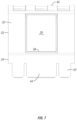
- the underside of the upper member 30 is shown in Figure 7 .
- the lower surface 32 can include a boundary section 38 that can be formed by an extruded wall extending away from the lower surface 32.
- this boundary 38 is shown to be positioned generally on the curved portion 33 of the lower surface 32.
- the boundary 38 can be included as a section to position the adhesive 39, such as the glue board with the tacky surface.
- adhesive 39 such as the glue board with the tacky surface.
- Still other types of adhesive materials may be used, such as, but not limited to, sprays, gels, liquids, glues, solids, and the like.
- the boundary 38 can provide guidance for orienting the adhesive material such that the adhesive will be substantially aligned with the cutout 20 of the lower housing member 12, which will aid in catching more insects as they pass under and/or through the station. It should be appreciated, however, that the boundary 38 need not be included in all embodiments, and that the adhesive could be included in the recessed portion 22 of the lower housing member 12, as has been previously disclosed.
- Additional aspects of the upper housing include tabs 42 that are inserted into the base member 50, as well as a central tab or snap member 44.
- the outer tabs 42 are substantially spaced and aligned with the lower tabs 26 of the lower housing member 12, as is shown in Figure 3 . This allows the pair of tabs 26, 42 to be insertable into the slots 52 of the base member 50, and can aid in the positioning and orientation of the insect monitoring station 10.
- the upper housing member 30 can include a central tab 44, which may also be known as a snap member.
- the central tab includes a protruding portion 46, which is to interact with a cutout 56 in the base body 51, which will removably secure the lower and upper housing member 12, 30 to the base 50.
- the snap member 44 can be activated by a button 48 of the upper housing 30. The button 48, when depressed, will press the central tab 44 as well. Lowering the tab 44 enough will allow the protruding portion 46 to become disengaged from the base cutout 56, which will allow the lower and upper housing members 12, 30 to be released from the base 50.
- the tabs of the housing members are aligned with the slots of the base 50 and the housing members are inserted until the protruding portion 46 of the central tab 44 is repositioned in the base cutout 56.
- the central tab 44 is generally resilient, this will hold the housing members in place relative to the base, such that the monitoring station 10 can be positioned in generally any orientation and at generally any location.
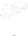
- the base 50 is shown in isolation in Figure 8 .
- the base 50 includes a base body 51.
- Tab slots 52 are positioned through the body on opposite sides of the snap slot 54. The slots are configured to align with the tabs 26, 42, 44 of the housing members.
- the cutout 56 is also shown in Figure 8 , and is positioned to receive the protruding member 48 of the central tab 44, which aids in holding the components of the monitoring station together.
- the base 50 can be positioned at generally any location to determine if insects are present.
- the base 50 and thus, the insect station 10 can simply be put on a ground surface, such as the floor, without securing the station 10 in place.
- the tabs 58 or other securing means can be utilized. This can be especially helpful when the surface attaching the station to is a ceiling, vertical wall, or other non-horizontal surface.
- the base 50 can be secured to the surface in a number of ways.
- the tabs 58 can be used with screws, bolts, hooks, rods, pins, or other connecting or surface penetrating members to extend through the tabs and into the surface.
- the connection members would hold the base 50 and any connecting housing members in place independent of the orientation thereof.
- adhesives could also be added to the base to removably secure the base 50 to a surface at any orientation.
- a recess, such as a groove can be formed into the underside of the base 50 (opposite the snap cutout 56) to receive and house and adhesive, when used.
- the adhesive could also be placed at the underside of the tabs 58 for removably securing the base to a surface.
- the base 50 and corresponding insect station could be secured to a surface at generally any orientation, configuration, or the like.
- the base 50 can take generally any shape as well.
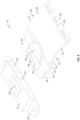
- Figure 9 shows a base 50 that is shaped different than the base of Figures 1-8 .
- the base in Figure 9 includes many of the same features as those previously disclosed, which allows the base to be used with the housing members to form the insect station as has been disclosed and described.
- the insect station 10 as has been shown and described provides a hinged book style station, with an upper housing 30 and lower housing 12 hingeably connected to one another such that the housings can be opened.
- An adhesive is positioned generally between the housings 12, 30, with at least a portion of a tacky part of the adhesive 39 being exposed to and through a lower surface 14 of the lower housing 12.
- the housings include a curved portion, with the curved portion 15 of the lower surface 14 of the lower housing 12 having a height 28 at the peak of the curve.
- the height is preferred to be from about 1/8 inches to about 1/2 inches, and more preferably to be about 1/4 inches. This height has been shown to be most effective in catching an insect, such as the wings of the insect, to the adhesive for trapping the insect to the insect station 10.
- an adhesive 39 is positioned in the hinged housing members, and a location is determined for determination of a number of insects in an area.
- a base 50 may be removably secured at the selected location, such as by screws, adhesives, pins, hooks, bolts, rods, or other connecting members to hold the base 50 in place.
- the housings with the adhesive are attached to the base 50 by aligning the tabs of the housings with the slots of the base 50. This may also include inserting at least one resilient tab with a protruding member to become positioned in at least one cutout of the base 50, wherein the tab and base interact to be held in place.
- the station 10 checked to determine the number of insects caught by the station.
- the number of insects attached to the adhesive can be an alert as to an infestation or to determine if a more aggressive extermination is required to rid the area of the insects. Therefore, the insect station 10 can be used as a monitoring device to alert a user if there is an insect problem at the location of the station 10.
- the insect station 10 is small enough to be generally non-noticeable in use, but large enough that the adhesive is able to collect a number of insects to determine if there is an insect problem.
- the station 10 can also be varied in size to monitor insects and bugs of different sizes.
- additional means for attracting insects to the station can be used, such as adding an attractant to the underside of the curved portion or on the surface opposite the curved surface of the lower housing member.
- Pesticides could also be added on and around the components of the insect station 10. The pesticides could be used to stick to the insects that may not adhere to the tacky surface of the adhesive. The insects would still take the pesticides with them and could pass these on to other insects, thus eliminating a number of insects not caught by the station.
- additional tacky surfaces can be provided to attempt to capture a larger number of bugs and insects.
- Baits are formulated as granules or solid blocks, gels, or liquids. Some bait products already have the active ingredient in the bait station, and others are packaged as a liquid that is poured into a bait container provided in the package. Gels typically come packaged with a syringe or a tube for dispensing. It is to be appreciated, that the use of varying types and ingredients for the pesticides could be used in order to prevent the buildup of a resistance to the pesticide. Therefore, according to at least some aspects of the invention, it is recommended to rotate use of a pesticide with the insect station when a pesticide is to be included.
- the present invention is not to be limited to particular pesticides, however, and it is to be appreciated that generally any type of approved pesticide could be used in conjunction with the insect station.
- the pesticides could be included in, on, and/or around the portions of the insect station, such as a coating on a surface or granules dispersed in the tacky surface of the adhesive.
- a secondary element with the station as has been described can provide for additional benefits.
- a secondary element such as a glue board, attractant, pesticide, or some combination positioned at or near the station can further provide the benefit of killing both the insects in contact with the elements, as well as with controlling insect colony populations.
- a mat, coupon, board, or other secondary member can be positioned at or near a station, such as under the lower member of the housing. This secondary member can be coated or otherwise incorporated with an attractant, glue, pesticide, dust, killing agent, or some combination thereof.
- a killing agent could be utilized that attaches or is ingested by a crawling insect such that the insect is able to return to its colony before the effects of the agent are fully felt. At this point, the agent can be passed to the other members of the colony, which could in effect, eliminate an entire population of insects in an area.
- the monitoring station can provide protection for the secondary member or element.
- killing and/or control agents have been disclosed, it is to be appreciated that this is not to be an exhaustive list.
- any pesticide or killing agent is contemplated to be included or used with a monitoring station. This includes, but is not limited to, repellant and non-repellant pesticides, dusts, aerosols, glues, and the like.
- a crawling insect can come in contact with the killing agent when approaching the station.
- the station provides a covered area that shelters the insect from light, which makes it an attractive location.
- the insect returns to its colony, it can take back portions of the killing agent to spread to other insects in order to kill off other members of the colony population.
- a colony was prepared in which approximately 100 cockroaches formed said colony. These consisted of 20 adult males, 30 adult females, and 50 nymphs. It was found that the use of the insect station with a one-inch panel containing a glue, an attractant tablet, and a non-repellant pesticide killed 99% of the colony within one week of introduction. Using only the attractant and a non-repellant pesticide killed 55% of the colony after one week, and just the use of the pesticide resulted in 31% of the colony being killed within one week of introduction.
- the components of the insect station can comprise a number of materials, such as rigid materials.
- the components may comprise molded polymers that are attached to one another.
- the material used to form the housing may be translucent to allow for visual inspection, if desired. While the station has been described as being made from a molded plastic, it can also be formed from any structurally rigid material such as steel, aluminum, cardstock, wood, or other material.
- the housing members may comprise a one-piece molded object or printed object (e.g., 3D printed), wherein the finished product includes the two housing members being rotatable to one another.
- the opening ability of the housing members, and the removability of the housing members from the base allows for a simple design that can be inspected, maintained, and serviced with ease. This can include monitoring of the adhesive, replacing the adhesive, and/or replenishing or refreshing the attractants and/or pesticides.
- the insect station 10 can include a first panel or bottom member that is preferably generally planar and has a surface configuration to provide a surface which can be tacky or contain a pesticide.
- the panel is preferably a flat panel, but may also be curved, formed with angled panels, have a wavy surface or otherwise be formed as desired for the particular crawling insect.
- the member can be connected to a top member, which may be one or both of the housings, either directly or through one or more intermediate members.
- a top member which may be one or both of the housings, either directly or through one or more intermediate members.
- one or more side walls may be included that connect the bottom member to the top member(s).
- the top member may be connected to the bottom member by another hinge or be slideably connected so as to be easily replaceable.
- the top member can be curved to include a rolled or domed structure.
- the space in between the top member and the bottom member can forms an interior that has one or more openings.
- the interior height between the housing members can be similar to the height of the lower housing curved surface, as previously disclosed.
- a pesticide can be applied to a lower surface of the top member. Alternatively, the pesticide may be applied to an upper surface of the bottom member.
- a tacky or sticky substance such as an adhesive, can be added opposite the pesticide on the interior of the station 10. In this manner, the pesticide and the sticky substance are contained within the interior, thus increasing their protection from water, light and other potential environmental contaminents. This also helps to minimize the potential for human contact with potentially hazardous surface treatments and maximizes the life of the pesticides used against the crawling insects. As they are on opposite sides of the interior, the pesticide acts with the crawling insect that is not caught by the sticky substance.
- the insect station 10 of the invention may be a molded plastic housing.
- the housing can include a first side and a second side.
- a thin side wall on the first side acts as a hinge and a snap or other securing means secured at the second side allows for the interior to be accessed as desired. This allows the user to check to see how many insects have been captured and to monitor for insect activity.
- the material used to form the housing may be translucent to allow for visual inspection, if desired. While the station has been described as being made from a molded plastic, it can also be formed from any structurally rigid material such as steel, aluminum, cardstock, wood, or other material.
- the housing is the size of a deck of cards or half a deck of cards.
- An additional aspect of the invention is the provision of an easily removable and replaceable station 10.
- a bottom member of the housing is removably secured to the wall or desired surface.
- the bottom member may be slidably received in a second base member that is secured to the wall.
- the second base member may be screwed, glued or otherwise secured to the wall to keep it in place both during use and when the remainder of the station 10 is removed for service or replacement.
- an attractant or other portions of the station 10 can be replaced without needing to replace the entirety of the housing 10.
- the pesticide or sticky surface may be placed on one or more removably secured chemistry panels.
- the removably secured chemistry panel may be slidably removable or secured by removable tape, hook and loops, or other means to the interior of the station 10. This allows a user to replace only the desired portion of the station 10.
- the insect station 10 of the invention can be used in conjunction with other monitoring systems, such as electronic, remote monitoring systems.
- the station 10 could interface with such an electronic monitor such that it would reduce or otherwise mitigate false positive signals of the electronic monitors and would maximize signals related to crawling pests.
- the station 10 could protect or otherwise be positioned in the vicinity of an electronic sensing device, such as those disclosed in U.S. patent application numbers 12/414,155 , 10/400,952 , and 10/400,951 , which are hereby incorporated by reference in their entirety.
- the sensing device generally senses the presence of crawling insects that may interact with the insect station 10 of the invention. This includes any insects that may be within the vicinity of the station.
- the station 10 of the invention could serve as a physical filter to reduce false positive signals from the sensing device and maximize signals related to the crawling pests in the vicinity. This could be done by the use of a camera sensing the station 10 such that a user can view the number of insects crawling in, on, or around the station 10.
- Other electronics such as optical sensors, ultrasonic sensors, proximity sensors, and the like, could be used in conjunction with the station 10 to aid in determining a number of insects in an area, such as that in or around the area of the insect station 10.
- a sensor could be operatively connected to the insect station 10 to provide an alert to the electronic sensing system to indicate that an insect has crawled in the area covered by the insect station 10.
- the alerts would indicate to a user that there is insect activity in or around the insect station such that the user could know to check the insect station for the amount of insects caught.
- the combined use and interfacing of the insect station 10 and an electronic sensing system would provide yet another layer of alert, monitoring, and/or data for a user to indicate if there is a problem with insects that may need to be addressed in another manner. Therefore, it is to be appreciated that the combination and/or interfacing of the insect station 10 can be done with generally type of monitoring system used or considered for monitoring the number of crawling insects.
- Embodiments of the present invention are further defined in the following nonlimiting Examples. It should be understood that these Examples, while indicating certain embodiments of the invention, are given by way of illustration only. From the above discussion and these Examples, one skilled in the art can ascertain the essential characteristics of this invention, and without departing from the spirit and scope thereof, can make various changes and modifications of the embodiments of the invention to adapt it to various usages and conditions. Thus, various modifications of the embodiments of the invention, in addition to those shown and described herein, will be apparent to those skilled in the art from the foregoing description. Such modifications are also intended to fall within the scope of the claims.
- a large food tote was prepared by first greasing the middle of the food tote with a thin layer of insect grease and then placing a piece of rodent chow, cardboard harborage and moistened water wick in the food tote. Carbon dioxide was then used to anesthetize tubs of German cockroaches of the appropriate ages. The number of cockroaches per tote was determined so that for each test bait, there are three totes of 20 adult male cockroaches, 30 gravid female cockroaches, and 50 cockroach nymphs. The cockroaches were allowed a minimum of 24 hours to recover from the effects of the carbon dioxide prior to testing.
- the three monitors were videotaped and the first sixty interactions with each trap were counted.
- the three monitors were a commercially available trap comprising a generic tented paper cockroach monitor with a glue board on the floor of the tent (Monitor A), a commercially available cockroach monitor comprising a round plastic cockroach with ramps leading to a glue board and including an attractant tablet placed on the glue board (Monitor B), and a monitor exemplary of the disclosure (Disclosure Monitor).
- Monitor B also include a top that conceals from view cockroaches that are caught on the glue board.
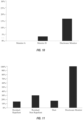
- Figure 10 represents the number of cockroaches caught during the first 60 interactions.
- the Disclosure Monitor achieved a significantly higher percentage of interactions resulting in a catch. Monitor A did not catch anything and Monitor B caught less than 5%, whereas the Disclosure Monitor caught nearly 20%.
- Example 1 The previously described test preparation of Example 1 was modified by including a 1 inch panel with a pesticide formulation.
- a liquid residual known for being repellant to insects a liquid residual known for not being repellant to insects, and dust formulation of a pesticide were placed in the colony testing containers.
- the embodiment of the present invention contained a glue board, an attractant tablet, and a treatment of non-repellent pesticide.
- Figure 11 shows data collected from the colony after 1 week. As Figure 11 shows, the present invention achieved a 99% mortality after one week of interaction. This was substantially better than the control pesticides.
- the residual non-repellant had the second highest mortality rate, which was only 30%.
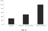
- Example 2 Using a modified test procedure from Example 2, the different components of the invention were test separately. A 1 inch panel was used for the treatment of pesticide. The prototype contained a glue board, an attractant tablet and a treatment of a non-repellant pesticide. Figure 12 shows that present invention (the Disclosure Monitor) achieved a 99% mortality after one week of interaction. Again, the exemplary apparatus and pesticide of the invention significantly outperformed the controls. The second highest mortality rate was the residual with an attractant tablet and that achieved less than 60% mortality.
Abstract
Description
- This application claims priority to
U.S. Patent Application Serial No. 14/626,254 filed on February 19, 2015 U.S. Patent Application Serial No. 15/005,642 filed on January 25, 2016 , the disclosures of which are incorporated herein by reference their entireties. - This invention relates generally to a crawling insect pest monitor and/or product transfer station and more particularly to a device for use on the exterior or interior of a structure for attracting and killing crawling insect pests entering the station. The crawling pest station is designed to monitor for pest activity in the zone of influence and to expose visiting pests to slow-activating pesticide treatments that result in a transfer of pesticide product back to areas that harbor such crawling insect pests, which will also aid in killing off a colony of insects. The crawling pest station is designed to protect pesticides and tacky surfaces so as to maximize their effective life-span.
- Crawling pests, such as the German cockroach (Blattella germanica) are well known to carry disease and are widely considered to be undesirable insects. The German cockroach is a smaller member of the cockroach family and is frequently a pest in food processing and preparation areas including hotels, nursing homes, hotels and other institutions. They are widespread pests capable of surviving in many different parts of the world. They are a type of thigmotactic insect, meaning that they generally react to a physical stimulus, and here prefer tight spaces. Such insects frequently hide out of sight in cracks and crevices that are easy for humans to overlook. Such insects also reproduce rapidly and thus are susceptible to treatments that are slow acting and can be transferred between pests.
- Numerous designs of crawling insect pest stations are commercially available, some use large containment areas, while others use wide open, flat surfaces with various forms of attractants and capture mechanisms, such as glue boards. Problems exist with such devices. For example, cockroaches have been observed to contact the edges of glue boards and escape. It was discovered that when such glue boards were rolled into cylinders, cockroaches would fill the underside of the glue roll. Similarly, a flat glue board was placed with its glue side or sticky side down and another flat glue board was placed with its sticky side up. It was found that the entire surface of the glue side down board was filled while only the edges of the sticky side up board were filled. Thus, it is desirable to provide a crawling insect monitor that is directed to crawling insets who desire small, narrow, or covered spaces.
- Many of the currently available crawling insect pest stations also leave the glue surface or the pesticide surface exposed to environmental conditions such as light, water and physical objects that could impact effectiveness. This also leaves potentially hazardous substances typically found in glues and pesticides exposed to potential human contact. This also exposes the pesticides and glues to other physical contacts that may erode their presence and thus minimize their effectiveness. It is therefore also desirable to provide an attraction station having features that are effective at concealing and protecting the attracting, trapping, and killing areas of the station.
- It is further desirable to provide an attraction station that maximizes the effectiveness of pesticides and allows for safe monitoring and killing of crawling insects and insect colonies while providing a dual action treatment that either captures the crawling insect or exposes the insect to pesticide.
- In one embodiment, the invention is a crawling pest monitor and a product transfer station designed to hold and protect a pest attractant, a pest trapping mechanism and a pesticide. The crawling pest station is designed to monitor for pest activity in the zone of influence and expose visiting pests to slow-acting pesticide treatments that result in a transfer of pesticide product back to harborage areas.
- A domed container having a base member which may be flat, curved or of varying contour, a curved or angled upper member connected directly or by one or more intermediate members to the base member, a tacky surface on one of the base member or the upper member, the tacky surface either being a tacky substance applied directly to the base member's upper surface / upper member's lower surface or to another piece of material that this secured to the base member or upper member, a pesticide which is placed opposite the tacky surface on the interior of the station, such as being either applied directly to the curved upper member's lower surface or removably secured to the upper member's lower surface, and an attractant placed in between the upper member and the base member.
- In another embodiment, the invention is a wall-mounted attraction station for killing crawling insects. The station includes at least one member mounted to a wall, preferably removably mounted to the wall. This may be accomplished with a station that includes a base member that is secured to the wall by screws, tape, glue or other means. Alternatively, the base member may releasably connect to a second base member which is secured to the wall. For example, the station's base member may slide into the second base member so as to allow the station to be monitored easily, cleaned, replaced or refreshed as necessary.
- It is further included to provide an attraction station that protects a sensing device that senses the presence of crawling insects that interact with the attraction station or that crawl in the vicinity of the attraction station. The attraction station can serve as a physical filter to reduce false positive signals from the sensing device and maximize signals related to crawling pest activity in the vicinity.
- The invention relates to the following aspects:
- 1. A system for detecting and reducing a population of a colony of crawling insects, the system comprising:
- an insect station comprising a curved bottom member and a curved top member and an adhesive positioned therebetween at an aperture in the bottom member; and
- a secondary element positioned at least partially below the bottom member of the insect station and configured to kill one or more members of the population of the crawling insect colony.
- 2. The system of aspect 1, wherein the insect station further comprises:
- the bottom member having an upper surface and a lower surface with a portion of the lower member curved and having the aperture in the lower member at the curved portion;
- the top member operatively connected to the bottom member, the top member having a top member upper surface and a top member lower surface and being at least partially curved substantially equal to the curved portion of the lower member; and
- the adhesive on at least a portion of the top member lower surface at least partially aligning with the aperture of the lower member.
- 3. The system of aspects 1 or 2, wherein the secondary element comprises a pesticide.
- 4. The system of aspect 3, wherein the pesticide is a non-repellant pesticide.
- 5. The system of aspect 3, wherein the secondary element further comprises an attractant.
- 6. The system of aspect 3, wherein the secondary element further comprises an adhesive element.
- 7. The system of any of the preceding aspects, further comprising an insect attractant on at least a portion of the lower surface of the bottom member.
- 8. The system of aspect 7, wherein the adhesive comprises a glue board, tape, glue, or spray.
- 9. The system of aspects 1 or 2, wherein the secondary element comprises a glue board, an attractant, and a non-repellant pesticide.
- 10. The system of aspects 1 or 2, further comprising a sensor for alerting when the system has interacted with a crawling insect.
- 11. A method for detecting and reducing a population of a colony of crawling insects, the method comprising:
- providing a monitoring station comprising a housing member having a curved portion and one or more substantially planar portions, and an adhesive operatively positioned such that the adhesive is at least partially exposed at or near a lower surface of the curved portion of the housing member;
- positioning a secondary element at least partially below the housing member, said secondary element configured to kill one or more members of the population of the crawling insect colony.
- 12. The method of aspect 11, further comprising adding an attractant to the secondary element to attract one or more crawling insects.
- 13. The method of aspect 11, further comprising adding a non-repellant pesticide to the secondary element to aid in killing the one or more members of the population of the crawling insect colony.
- 14. The method of aspect 11, further comprising adding an adhesive to the secondary element.
- 15. The method of aspect 11, further comprising monitoring the station and secondary element to determine if crawling insects are being killed.
- 16. The method of
aspect 15, wherein the step of monitoring the station and secondary element comprises remotely viewing a location in which the station and secondary element are located. - 17. The method of
aspect 16, further comprising remotely alerting when one or more crawling insects have interacted with the monitoring station or secondary element. - 18. A kit for detecting and reducing a population of a colony of crawling insects, the kit comprising:
- a monitoring station comprising a housing member having a curved portion and one or more substantially planar portions, and an adhesive operatively positioned such that the adhesive is at least partially exposed at or near a lower surface of the curved portion of the housing member; and
- a secondary element configured to kill one or more members of the population of the crawling insect colony.
- 19. The kit of
aspect 18, wherein the secondary element comprises a glue board. - 20. The kit of
aspect 19, further comprising a repelling or non-repelling pesticide for use with the secondary element. - 21. A monitoring station for killing crawling insects and monitoring the number of insects in a location, comprising:
- a bottom member having an upper surface and a lower surface with a portion of the lower member curved and having a cutout in the lower member at the curved portion;
- a top member operatively connected to the bottom member, the top member having a top member upper surface and a top member lower surface and being at least partially curved substantially equal to the curved portion of the lower member;
- an adhesive on at least a portion of the top member lower surface at least partially aligning with the cutout of the lower member.
- 22. The monitoring station of aspect 21, wherein said bottom and top members hingeably connected to one another.
- 23. The monitoring station of
aspects 21 or 22, further comprising an insect attractant on at least a portion of the lower surface of the bottom member. - 24. The monitoring station of
aspects 21, 22, or 23, wherein said top member comprises a defined area for the adhesive. - 25. The monitoring station of
aspects - 26. The monitoring station of
aspects - 27. The monitoring station of
aspect 26, wherein said base is removably securable to a surface. - 28. The monitoring station of aspect 27, wherein the base comprises a plurality of slots, and the bottom member and top member comprise tabs extending therefrom for being inserted into the slots of the base.
- 29. The monitoring station of aspect 27, wherein said base comprises tabs for removably securing the base to the surface.
- 30. The monitoring station of
aspect aspects - 31. A monitoring station for killing crawling insects and monitoring the number of insects in a location, comprising:
- a housing member having a curved portion and one or more substantially planar portions;
and - an adhesive operatively positioned such that the adhesive is at least partially exposed at or near a lower surface of the curved portion of the housing member.
- a housing member having a curved portion and one or more substantially planar portions;
- 32. The monitoring station of aspect 31, wherein a lower surface of the curved portion of the housing is from about 1/8 inches to about 1/2 inches from the substantially planar portion.
- 33. The monitoring station of
aspect 32, wherein the lower surface of the curved portion is approximately 1/4 inches from the substantially planar portion. - 34. The monitoring station of
aspects 31 or 32, wherein the housing member having a cutout at the curved portion and the adhesive positioned at the cutout. - 35. The monitoring station of
aspect 34, further comprising an upper housing member operatively connected to the housing member and the adhesive positioned at a lower surface of the upper housing member to be exposed through the cutout to the lower surface of the curved portion of the housing member. - 36. The monitoring station of aspect 35, further comprising a base operatively connectable to the housing members, wherein said base being removably securable to a surface.
- 37. A monitoring station for monitoring and killing insects at a location, the station comprising:
- a lower housing member comprising a curved portion and a cutout in said curved portion;
- an upper housing member comprising a curved portion for interacting with the curved portion of the lower housing member, said upper housing member operatively connected to the lower housing member; and
- an adhesive positioned at the cutout of the lower housing member.
- 38. The monitoring station of
aspect 37, wherein the adhesive positioned on a lower surface of the upper housing member and positioned to be exposed at the cutout of the lower housing member. - 39. The monitoring station of aspect 38, further comprising a base operatively connected to the lower and upper housing members for removably securing the housing members to a surface.
- 40. The monitoring station of
aspect 39, wherein a lower surface of the curved portion of the lower housing member approximately from about 1/8 inches to about 1/2 inches away from the surface. -
-
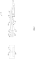
Figure 1 is a perspective view of an insect monitoring station according to aspects of the invention. -
Figure 2 is a side elevation view of the insect monitoring station ofFigure 1 . -
Figure 3 is a top plan view of the insect monitoring station ofFigure 1 . -
Figure 4 is another perspective view of the insect monitoring station in a partially open configuration. -
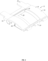
Figure 5 is perspective view of bottom member of the insect monitoring station according to aspects of the invention. -
Figure 6 is a perspective view of a top member of the insect monitoring station according to aspects of the invention. -
Figure 7 is a bottom plan view of the top member ofFigure 6 . -
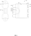
Figure 8 is a perspective view of a base member of the insect monitoring station according to aspects of the invention. -
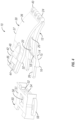
Figure 9 is a perspective view of yet another embodiment of an insect monitoring station according to aspects of the invention. -
Figure 10 is a graph indicating the number of insects caught during the first 60 interactions. -
Figure 11 is a graph indicating the mortality of insects after 1 week of exposure to the invention as compared to other commercially available products. -
Figure 12 is a graph indicating the morality of insects after 1 week of exposure to the components of the invention. - Various embodiments of the present invention will be described in detail with reference to the drawings, wherein like reference numerals represent like parts throughout the several views. Reference to various embodiments does not limit the scope of the invention. Figures represented herein are not limitations to the various embodiments according to the invention and are presented for exemplary illustration of the invention.
- The figures show exemplary features and concepts of the invention by illustration. The intent of the preferred embodiments of the invention is to provide features that both attract and kill crawling insects on the interior of a structure in a shortened or finite window of time, while also exposing insects to an agent that can be taken back to a colony to reduce and/or eliminate a population of insects making up the colony. The window of time being measured generally from when the crawling insect enters an area, such as the interior or exterior area of the structure, and until the crawling insect is attracted to and killed by the attraction station. The stations can be used to monitor an area to determine if the area has an insect infestation that needs to be addressed with additional methods. Furthermore, a killing agent can be introduced at the station that can kill the insects at the station and also be taken back to the colony by an insect to reduce and/or eliminate the population of the colony.
- Exemplary features and aspects of the present invention for monitoring, attracting, and killing crawling insects, such as cockroaches, beetles, etc., within a shortened window of time are illustrated in
Figs. 1-9 . For example,Figs. 1-4 show various views of aninsect monitoring station 10 according to aspects of the invention. Themonitoring station 10 includes alower housing 12 and anupper housing 30 that are in rotatably communication with one another. As shown in the figures, this may be accomplished by each of thehousing members hinge components Figures 1 and4 . InFigure 1 , thetop member 30 is rotated to a closed position where it is in contact or near contact with thelower housing member 12. However, inFigure 4 , thetop housing member 30 has been rotated via the hinge to allow access to an interior between the lower andupper members - It should be appreciated that, although the
monitoring station 10 is shown to have two housing members each havinghinge components station 10 to monitor, modify, clean, replace, or otherwise manipulate thestation 10, as needed. - The
lower housing member 12 is shown throughout the figures, and is isolated inFigure 5 . Thelower housing member 12 includes alower surface 14 and anupper surface 18. Thelower surface 14 includes a substantiallyplanar portion 16 and a curved ordomed portion 15. For example, as shown inFigure 2 , theplanar portions 16 are positioned generally at each end of the curved ordomed portion 15. The planar portions are not necessary in all embodiments. - Furthermore, it should be noted that the height of the peak of the
curved portion 15 of thelower surface 14 has aheight 28, which can be defined as the distance between the peak and theplanar portions 16, or the peak and the surface to which the insect station is located. It is preferred in some embodiments that theheight 28 of the peak of thecurved portion 15 be from about 1/8 inches to about 1/2 inches. More preferably, theheight 28 of the peak of thecurved portion 15 is about 1/4 inches. This height has been determined to be most effective for capturing insects traveling underneath, as will be explained. The width of thecurved portion 15 can vary, and is not to be limiting to the invention. - The
upper surface 18 of thelower housing member 12 also includes acurved portion 19, which runs substantially parallel with thelower surface 14. This also includes the substantially planar portions. - Other aspects of the
lower housing member 12 include acutout 20 through the upper and lower surfaces of thelower housing member 12, which can include a recessedsection 22 generally outlining thecutout 20 and extending only partially through the surfaces. As will be understood, an adhesive 39 can be positioned at thecutout 20 and relative to thelower housing member 12 such that is exposed through the cutout towards thelower surface 14. The adhesive 39, in some embodiments, could be a glue board or other structure with a tacky surface that can be positioned at thecutout 20. For example, it is contemplated that the adhesive 39 could be a glue board that is sized to fit within the recessed portion so that the ledge of the recessedportion 22 contacts a portion of the tacky surface to hold the adhesive 39 in place at thecutout 20. Insects that walk under the domedlower housing member 12 can contact the adhesive, such as by their wings contacting the tacky substance exposed through thecutout 20, and can become stuck thereat to trap the insect. Furthermore, to attract more insects into walking under the domed lower housing, an attractant may be added to thelower surface 14 of thelower housing 12 to lure the insect toward the adhesive 39 exposed at the cutout. - It should further be appreciated that, when only one housing is included, the cutout need not be included, and instead, the adhesive can be positioned directly on the underside of the domed/
curved portion 15 of thelower surface 14. However, having thecutout 20 and theupper housing 30 will allow for easier access to the adhesive 39 such that it can be removed, examined, and/or replaced. - Extending from the
lower housing member 12 at a side generally opposite thehinge 24 is a plurality oftabs 26. Thetabs 26 are spaced apart and are configured to be inserted into abase member 50 to connect thelower housing member 12 thereto, which can temporarily connect thelower housing member 12 to thebase member 50. This connection, along with theupper housing member 30, will allow thestation 10 to be positioned on generally any surface and at generally any orientation. Therefore, theinsect station 10 is not limited in its ability to be used on or around any surface for trapping insects to monitor the level of insect infestation at a particular location. - As mentioned, the
insect station 10 shown in the figures also includes anupper housing member 30 rotatably attached to thelower housing member 12. Theupper housing member 30 includes alower surface 32 and anupper surface 36 as well. Thelower surface 32 may include portions that are substantially parallel to thelower housing 12, such as having one or more substantiallyplanar portions 34 and acurved portion 33. Thecurved portion 33 may generally match the curve of the upper and lower surfaces of thelower housing member 12. This is also the case for theupper surface 36, which can include a similarcurved portion 37. In addition, theupper housing member 30 includes ahinge portion 40 for communicating and/or interacting with thehinge portion 24 of thelower housing member 12 in order to allow theupper housing 30 to rotate relative to the lower housing. For example, in the figures, thehinge portion 40 of theupper member 30 is shown to have a plurality of rod or axle like members spaced by spacers. The hingedportion 24 of thelower member 12 is shown to have snap or clasping features that are able to snap onto the rods and to be held thereat to allow the rotation to occur. - The underside of the
upper member 30 is shown inFigure 7 . As shown, thelower surface 32 can include a boundary section 38 that can be formed by an extruded wall extending away from thelower surface 32. InFigure 7 , this boundary 38 is shown to be positioned generally on thecurved portion 33 of thelower surface 32. The boundary 38 can be included as a section to position the adhesive 39, such as the glue board with the tacky surface. Still other types of adhesive materials may be used, such as, but not limited to, sprays, gels, liquids, glues, solids, and the like. The boundary 38 can provide guidance for orienting the adhesive material such that the adhesive will be substantially aligned with thecutout 20 of thelower housing member 12, which will aid in catching more insects as they pass under and/or through the station. It should be appreciated, however, that the boundary 38 need not be included in all embodiments, and that the adhesive could be included in the recessedportion 22 of thelower housing member 12, as has been previously disclosed. - Additional aspects of the upper housing include
tabs 42 that are inserted into thebase member 50, as well as a central tab or snapmember 44. Theouter tabs 42 are substantially spaced and aligned with thelower tabs 26 of thelower housing member 12, as is shown inFigure 3 . This allows the pair oftabs slots 52 of thebase member 50, and can aid in the positioning and orientation of theinsect monitoring station 10. - Furthermore, the
upper housing member 30 can include acentral tab 44, which may also be known as a snap member. The central tab includes a protrudingportion 46, which is to interact with acutout 56 in thebase body 51, which will removably secure the lower andupper housing member base 50. Thesnap member 44 can be activated by abutton 48 of theupper housing 30. Thebutton 48, when depressed, will press thecentral tab 44 as well. Lowering thetab 44 enough will allow the protrudingportion 46 to become disengaged from thebase cutout 56, which will allow the lower andupper housing members base 50. To re-attach the components, the tabs of the housing members are aligned with the slots of thebase 50 and the housing members are inserted until the protrudingportion 46 of thecentral tab 44 is repositioned in thebase cutout 56. As thecentral tab 44 is generally resilient, this will hold the housing members in place relative to the base, such that themonitoring station 10 can be positioned in generally any orientation and at generally any location. - The
base 50 is shown in isolation inFigure 8 . As mentioned, thebase 50 includes abase body 51.Tab slots 52 are positioned through the body on opposite sides of thesnap slot 54. The slots are configured to align with thetabs cutout 56 is also shown inFigure 8 , and is positioned to receive the protrudingmember 48 of thecentral tab 44, which aids in holding the components of the monitoring station together. - Also shown in
Figure 8 extending from the ends of the base 50 are securingtabs 58. The securing tabs orflanges 58 are shown to be curved members, but may take generally any shape or form. Furthermore, the securingtabs 58 are shown to include apertures thereto. The base 50 can be positioned at generally any location to determine if insects are present. For example, thebase 50, and thus, theinsect station 10, can simply be put on a ground surface, such as the floor, without securing thestation 10 in place. However, if thestation 10 is to be secured in position, thetabs 58 or other securing means can be utilized. This can be especially helpful when the surface attaching the station to is a ceiling, vertical wall, or other non-horizontal surface. The base 50 can be secured to the surface in a number of ways. For example, in the configuration shown inFigures 1-8 , thetabs 58 can be used with screws, bolts, hooks, rods, pins, or other connecting or surface penetrating members to extend through the tabs and into the surface. The connection members would hold thebase 50 and any connecting housing members in place independent of the orientation thereof. However, this is not to be the only way to secure thestation 10 to a surface. For example, adhesives could also be added to the base to removably secure the base 50 to a surface at any orientation. A recess, such as a groove, can be formed into the underside of the base 50 (opposite the snap cutout 56) to receive and house and adhesive, when used. The adhesive could also be placed at the underside of thetabs 58 for removably securing the base to a surface. In any manner, it is to be appreciated that thebase 50 and corresponding insect station could be secured to a surface at generally any orientation, configuration, or the like. - The base 50 can take generally any shape as well. For example,
Figure 9 shows a base 50 that is shaped different than the base ofFigures 1-8 . However, the base inFigure 9 includes many of the same features as those previously disclosed, which allows the base to be used with the housing members to form the insect station as has been disclosed and described. - Therefore, the
insect station 10 as has been shown and described provides a hinged book style station, with anupper housing 30 andlower housing 12 hingeably connected to one another such that the housings can be opened. An adhesive is positioned generally between thehousings lower surface 14 of thelower housing 12. The housings include a curved portion, with thecurved portion 15 of thelower surface 14 of thelower housing 12 having aheight 28 at the peak of the curve. The height is preferred to be from about 1/8 inches to about 1/2 inches, and more preferably to be about 1/4 inches. This height has been shown to be most effective in catching an insect, such as the wings of the insect, to the adhesive for trapping the insect to theinsect station 10. - In use, an adhesive 39 is positioned in the hinged housing members, and a location is determined for determination of a number of insects in an area. A base 50 may be removably secured at the selected location, such as by screws, adhesives, pins, hooks, bolts, rods, or other connecting members to hold the base 50 in place. The housings with the adhesive are attached to the
base 50 by aligning the tabs of the housings with the slots of thebase 50. This may also include inserting at least one resilient tab with a protruding member to become positioned in at least one cutout of thebase 50, wherein the tab and base interact to be held in place. - A selected amount of time is allowed to lapse, and then the
station 10 checked to determine the number of insects caught by the station. The number of insects attached to the adhesive can be an alert as to an infestation or to determine if a more aggressive extermination is required to rid the area of the insects. Therefore, theinsect station 10 can be used as a monitoring device to alert a user if there is an insect problem at the location of thestation 10. - The
insect station 10 is small enough to be generally non-noticeable in use, but large enough that the adhesive is able to collect a number of insects to determine if there is an insect problem. Thestation 10 can also be varied in size to monitor insects and bugs of different sizes. - Furthermore, additional means for attracting insects to the station can be used, such as adding an attractant to the underside of the curved portion or on the surface opposite the curved surface of the lower housing member. Pesticides could also be added on and around the components of the
insect station 10. The pesticides could be used to stick to the insects that may not adhere to the tacky surface of the adhesive. The insects would still take the pesticides with them and could pass these on to other insects, thus eliminating a number of insects not caught by the station. Still further, additional tacky surfaces can be provided to attempt to capture a larger number of bugs and insects. - There are many cockroach control products sold, including bait, gel, granule, and aerosol spray formulations. Baits are formulated as granules or solid blocks, gels, or liquids. Some bait products already have the active ingredient in the bait station, and others are packaged as a liquid that is poured into a bait container provided in the package. Gels typically come packaged with a syringe or a tube for dispensing. It is to be appreciated, that the use of varying types and ingredients for the pesticides could be used in order to prevent the buildup of a resistance to the pesticide. Therefore, according to at least some aspects of the invention, it is recommended to rotate use of a pesticide with the insect station when a pesticide is to be included. The present invention is not to be limited to particular pesticides, however, and it is to be appreciated that generally any type of approved pesticide could be used in conjunction with the insect station. Furthermore, the pesticides could be included in, on, and/or around the portions of the insect station, such as a coating on a surface or granules dispersed in the tacky surface of the adhesive.
- The addition of a secondary element with the station as has been described can provide for additional benefits. For example, while the station will allow for monitoring and killing of insects, the addition of a secondary element, such as a glue board, attractant, pesticide, or some combination positioned at or near the station can further provide the benefit of killing both the insects in contact with the elements, as well as with controlling insect colony populations. A mat, coupon, board, or other secondary member can be positioned at or near a station, such as under the lower member of the housing. This secondary member can be coated or otherwise incorporated with an attractant, glue, pesticide, dust, killing agent, or some combination thereof. For example, a killing agent could be utilized that attaches or is ingested by a crawling insect such that the insect is able to return to its colony before the effects of the agent are fully felt. At this point, the agent can be passed to the other members of the colony, which could in effect, eliminate an entire population of insects in an area.
- The monitoring station can provide protection for the secondary member or element. Further, while some examples of killing and/or control agents have been disclosed, it is to be appreciated that this is not to be an exhaustive list. For example, any pesticide or killing agent is contemplated to be included or used with a monitoring station. This includes, but is not limited to, repellant and non-repellant pesticides, dusts, aerosols, glues, and the like.
- It is contemplated that a crawling insect can come in contact with the killing agent when approaching the station. The station, as has been disclosed, provides a covered area that shelters the insect from light, which makes it an attractive location. When the insect returns to its colony, it can take back portions of the killing agent to spread to other insects in order to kill off other members of the colony population.
- Testing has shown that the combination of the insect station and a killing agent can greatly increase the mortality rate of a colony of insects. For example, in one such test, a colony was prepared in which approximately 100 cockroaches formed said colony. These consisted of 20 adult males, 30 adult females, and 50 nymphs. It was found that the use of the insect station with a one-inch panel containing a glue, an attractant tablet, and a non-repellant pesticide killed 99% of the colony within one week of introduction. Using only the attractant and a non-repellant pesticide killed 55% of the colony after one week, and just the use of the pesticide resulted in 31% of the colony being killed within one week of introduction.
- The components of the insect station can comprise a number of materials, such as rigid materials. For example, the components may comprise molded polymers that are attached to one another. The material used to form the housing may be translucent to allow for visual inspection, if desired. While the station has been described as being made from a molded plastic, it can also be formed from any structurally rigid material such as steel, aluminum, cardstock, wood, or other material. In some embodiments, the housing members may comprise a one-piece molded object or printed object (e.g., 3D printed), wherein the finished product includes the two housing members being rotatable to one another. The opening ability of the housing members, and the removability of the housing members from the base, allows for a simple design that can be inspected, maintained, and serviced with ease. This can include monitoring of the adhesive, replacing the adhesive, and/or replenishing or refreshing the attractants and/or pesticides.
- Additional modifications or alternatives to the
insect station 10 as shown and described may be included. For example, theinsect station 10 can include a first panel or bottom member that is preferably generally planar and has a surface configuration to provide a surface which can be tacky or contain a pesticide. The panel is preferably a flat panel, but may also be curved, formed with angled panels, have a wavy surface or otherwise be formed as desired for the particular crawling insect. - The member can be connected to a top member, which may be one or both of the housings, either directly or through one or more intermediate members. For example, one or more side walls may be included that connect the bottom member to the top member(s). For example, the top member may be connected to the bottom member by another hinge or be slideably connected so as to be easily replaceable. The top member can be curved to include a rolled or domed structure. The space in between the top member and the bottom member can forms an interior that has one or more openings. The interior height between the housing members can be similar to the height of the lower housing curved surface, as previously disclosed.
- A pesticide can be applied to a lower surface of the top member. Alternatively, the pesticide may be applied to an upper surface of the bottom member. A tacky or sticky substance, such as an adhesive, can be added opposite the pesticide on the interior of the
station 10. In this manner, the pesticide and the sticky substance are contained within the interior, thus increasing their protection from water, light and other potential environmental contaminents. This also helps to minimize the potential for human contact with potentially hazardous surface treatments and maximizes the life of the pesticides used against the crawling insects. As they are on opposite sides of the interior, the pesticide acts with the crawling insect that is not caught by the sticky substance. - According to additional aspects of the invention, the
insect station 10 of the invention may be a molded plastic housing. The housing can include a first side and a second side. A thin side wall on the first side acts as a hinge and a snap or other securing means secured at the second side allows for the interior to be accessed as desired. This allows the user to check to see how many insects have been captured and to monitor for insect activity. The material used to form the housing may be translucent to allow for visual inspection, if desired. While the station has been described as being made from a molded plastic, it can also be formed from any structurally rigid material such as steel, aluminum, cardstock, wood, or other material. Preferably, the housing is the size of a deck of cards or half a deck of cards. - An additional aspect of the invention is the provision of an easily removable and
replaceable station 10. Preferably, a bottom member of the housing is removably secured to the wall or desired surface. For example, the bottom member may be slidably received in a second base member that is secured to the wall. The second base member may be screwed, glued or otherwise secured to the wall to keep it in place both during use and when the remainder of thestation 10 is removed for service or replacement. In this manner, an attractant or other portions of thestation 10 can be replaced without needing to replace the entirety of thehousing 10. Alternatively, the pesticide or sticky surface may be placed on one or more removably secured chemistry panels. The removably secured chemistry panel may be slidably removable or secured by removable tape, hook and loops, or other means to the interior of thestation 10. This allows a user to replace only the desired portion of thestation 10. - Still further, it should be appreciated that the
insect station 10 of the invention can be used in conjunction with other monitoring systems, such as electronic, remote monitoring systems. Thestation 10 could interface with such an electronic monitor such that it would reduce or otherwise mitigate false positive signals of the electronic monitors and would maximize signals related to crawling pests. For example, thestation 10 could protect or otherwise be positioned in the vicinity of an electronic sensing device, such as those disclosed inU.S. ,patent application numbers 12/414,15510/400,952 10/400,951 insect station 10 of the invention. This includes any insects that may be within the vicinity of the station. Thestation 10 of the invention could serve as a physical filter to reduce false positive signals from the sensing device and maximize signals related to the crawling pests in the vicinity. This could be done by the use of a camera sensing thestation 10 such that a user can view the number of insects crawling in, on, or around thestation 10. Other electronics, such as optical sensors, ultrasonic sensors, proximity sensors, and the like, could be used in conjunction with thestation 10 to aid in determining a number of insects in an area, such as that in or around the area of theinsect station 10. - Furthermore, a sensor could be operatively connected to the
insect station 10 to provide an alert to the electronic sensing system to indicate that an insect has crawled in the area covered by theinsect station 10. The alerts would indicate to a user that there is insect activity in or around the insect station such that the user could know to check the insect station for the amount of insects caught. - The combined use and interfacing of the
insect station 10 and an electronic sensing system would provide yet another layer of alert, monitoring, and/or data for a user to indicate if there is a problem with insects that may need to be addressed in another manner. Therefore, it is to be appreciated that the combination and/or interfacing of theinsect station 10 can be done with generally type of monitoring system used or considered for monitoring the number of crawling insects. - Embodiments of the present invention are further defined in the following nonlimiting Examples. It should be understood that these Examples, while indicating certain embodiments of the invention, are given by way of illustration only. From the above discussion and these Examples, one skilled in the art can ascertain the essential characteristics of this invention, and without departing from the spirit and scope thereof, can make various changes and modifications of the embodiments of the invention to adapt it to various usages and conditions. Thus, various modifications of the embodiments of the invention, in addition to those shown and described herein, will be apparent to those skilled in the art from the foregoing description. Such modifications are also intended to fall within the scope of the claims.
- The materials used in the following Examples are provided herein:
- Insect Grease (50/50 Petrolatum and Mineral Oil)
- Carbon Dioxide
- Laboratory strains of adult German Cockroaches (Blattella germanica), approximately 7 weeks old as well as German cockroach nymphs approximately 3 weeks old were reared on Rodent Chow in temperature ranges of 78-82°F, and approximately 30-40% relative humidity. Conditions of a 12 hour light: 12 hour dark cycle were used unless otherwise noted.
- For each replicate to be tested, a large food tote was prepared by first greasing the middle of the food tote with a thin layer of insect grease and then placing a piece of rodent chow, cardboard harborage and moistened water wick in the food tote. Carbon dioxide was then used to anesthetize tubs of German cockroaches of the appropriate ages. The number of cockroaches per tote was determined so that for each test bait, there are three totes of 20 adult male cockroaches, 30 gravid female cockroaches, and 50 cockroach nymphs. The cockroaches were allowed a minimum of 24 hours to recover from the effects of the carbon dioxide prior to testing.
- To determine the number of interactions between the cockroaches and the trap, three monitors were videotaped and the first sixty interactions with each trap were counted. The three monitors were a commercially available trap comprising a generic tented paper cockroach monitor with a glue board on the floor of the tent (Monitor A), a commercially available cockroach monitor comprising a round plastic cockroach with ramps leading to a glue board and including an attractant tablet placed on the glue board (Monitor B), and a monitor exemplary of the disclosure (Disclosure Monitor). Monitor B also include a top that conceals from view cockroaches that are caught on the glue board.
Figure 10 represents the number of cockroaches caught during the first 60 interactions. As shown, the Disclosure Monitor achieved a significantly higher percentage of interactions resulting in a catch. Monitor A did not catch anything and Monitor B caught less than 5%, whereas the Disclosure Monitor caught nearly 20%. - The previously described test preparation of Example 1 was modified by including a 1 inch panel with a pesticide formulation. In this test, a liquid residual known for being repellant to insects, a liquid residual known for not being repellant to insects, and dust formulation of a pesticide were placed in the colony testing containers. The embodiment of the present invention (the Disclosure Monitor) contained a glue board, an attractant tablet, and a treatment of non-repellent pesticide.
Figure 11 shows data collected from the colony after 1 week. AsFigure 11 shows, the present invention achieved a 99% mortality after one week of interaction. This was substantially better than the control pesticides. The residual non-repellant had the second highest mortality rate, which was only 30%. - Using a modified test procedure from Example 2, the different components of the invention were test separately. A 1 inch panel was used for the treatment of pesticide. The prototype contained a glue board, an attractant tablet and a treatment of a non-repellant pesticide.
Figure 12 shows that present invention (the Disclosure Monitor) achieved a 99% mortality after one week of interaction. Again, the exemplary apparatus and pesticide of the invention significantly outperformed the controls. The second highest mortality rate was the residual with an attractant tablet and that achieved less than 60% mortality. - While the crawling
insect station 10 here and before described is effectively adapted to fulfill the aforementioned objectives, it is to be understood that the invention is not intended to be limited to the specific preferred embodiments of the aspects disclosed and set forth above. Rather, it is to be taken as including all reasonable equivalents to the subject matter of the appended claims.
Claims (12)
- A system for detecting and reducing a population of a colony of crawling insects, the system comprising:an insect station comprising a base member, which may be flat, curved or of varying contour, an upper member connected directly or by one or more intermediate members to the base member, and an adhesive positioned therebetween at an aperture in the base member; anda secondary element positioned at least partially below the base member of the insect station and configured to kill one or more members of the population of the crawling insect colony.
- The system of claim 1, wherein the secondary element comprises a pesticide.
- The system of claim 2, wherein the pesticide is a non-repellant pesticide.
- The system of claim 2, wherein the secondary element further comprises an attractant.
- The system of claim 2, wherein the secondary element further comprises an adhesive element.
- The system of any of the preceding claims, further comprising an insect attractant on at least a portion of the lower surface of the base member.
- The system of claim 6, wherein the adhesive comprises a glue board, tape, glue, or spray.
- The system of claims 1 or 2, wherein the secondary element comprises a glue board, an attractant, and a non-repellant pesticide.
- The system of claims 1 or 2, further comprising a sensor for alerting when the system has interacted with a crawling insect.
- A method for detecting and reducing a population of a colony of crawling insects, the method comprising:
providing an insect station according o claims 1 to 9 including aidsecondary element configured to kill one or more members of the population of the crawling insect colony;and further comprising monitoring the station and secondary element to determine if crawling insects are being killed. - The method of claim 10, wherein the step of monitoring the station and secondary element comprises remotely viewing a location in which the station and secondary element are located.
- The method of claim 11, further comprising remotely alerting when one or more crawling insects have interacted with the monitoring station or secondary element.
Applications Claiming Priority (4)
| Application Number | Priority Date | Filing Date | Title |
|---|---|---|---|
| US14/626,254 US10123522B2 (en) | 2015-02-19 | 2015-02-19 | Insect pest monitor and product transfer station |
| US15/005,642 US10412952B2 (en) | 2015-02-19 | 2016-01-25 | Insect pest monitor and product transfer station |
| EP16753152.4A EP3258777B1 (en) | 2015-02-19 | 2016-02-19 | System and method for detecting and reducing a population of a colony of crawling insects |
| PCT/US2016/018690 WO2016134265A1 (en) | 2015-02-19 | 2016-02-19 | Insect pest trap and product transfer station |
Related Parent Applications (1)
| Application Number | Title | Priority Date | Filing Date |
|---|---|---|---|
| EP16753152.4A Division EP3258777B1 (en) | 2015-02-19 | 2016-02-19 | System and method for detecting and reducing a population of a colony of crawling insects |
Publications (2)
| Publication Number | Publication Date |
|---|---|
| EP4241561A2 true EP4241561A2 (en) | 2023-09-13 |
| EP4241561A3 EP4241561A3 (en) | 2024-02-28 |
Family
ID=56689312
Family Applications (2)
| Application Number | Title | Priority Date | Filing Date |
|---|---|---|---|
| EP16753152.4A Active EP3258777B1 (en) | 2015-02-19 | 2016-02-19 | System and method for detecting and reducing a population of a colony of crawling insects |
| EP23183064.7A Pending EP4241561A3 (en) | 2015-02-19 | 2016-02-19 | System and method for detecting and reducing a population of a colony of crawling insects |
Family Applications Before (1)
| Application Number | Title | Priority Date | Filing Date |
|---|---|---|---|
| EP16753152.4A Active EP3258777B1 (en) | 2015-02-19 | 2016-02-19 | System and method for detecting and reducing a population of a colony of crawling insects |
Country Status (6)
| Country | Link |
|---|---|
| US (2) | US10412952B2 (en) |
| EP (2) | EP3258777B1 (en) |
| CN (2) | CN107249319B (en) |
| CA (2) | CA3121482C (en) |
| DE (1) | DE202016008982U1 (en) |
| WO (1) | WO2016134265A1 (en) |
Families Citing this family (2)
| Publication number | Priority date | Publication date | Assignee | Title |
|---|---|---|---|---|
| WO2022051255A1 (en) | 2020-09-02 | 2022-03-10 | Ecolab Usa Inc. | Systems, methods, and apparatus for installation and servicing of an insect capture device |
| US20220192171A1 (en) * | 2020-12-17 | 2022-06-23 | OTS INVESTCO INC. (Ontario Corporation No 00243119) | Pest control system and method for use thereof |
Family Cites Families (25)
| Publication number | Priority date | Publication date | Assignee | Title |
|---|---|---|---|---|
| US4031654A (en) * | 1976-01-26 | 1977-06-28 | Gray James R | Insect trap |
| US4112609A (en) * | 1977-05-12 | 1978-09-12 | Kaveloski Robert J | Prefabricated disposable fly trap blank |
| US4787171A (en) * | 1987-06-01 | 1988-11-29 | Pierre Dagenais | Insect swatter |
| US5090153A (en) | 1991-02-25 | 1992-02-25 | Trece, Inc. | Insect monitoring system |
| IN192594B (en) | 1996-09-18 | 2004-05-08 | Johnson & Son Inc S C | |
| US5771628A (en) | 1996-10-25 | 1998-06-30 | Jeunique International, Inc. | Insect and pest trap |
| US5953854A (en) | 1996-12-13 | 1999-09-21 | The Clorox Company | Granular bait station |
| GB9814507D0 (en) | 1998-07-03 | 1998-09-02 | Univ Southampton | A method and apparatus for controlling pests |
| US6219960B1 (en) | 1998-10-28 | 2001-04-24 | Waterbury Companies, Inc. | Insect bait station |
| US6343434B1 (en) | 1999-02-16 | 2002-02-05 | John Michael Petti | Pest-activated bait dispensing system |
| US6651378B2 (en) | 2000-05-16 | 2003-11-25 | Stanley Z. Baker | Bait station for insects |
| GB2381181B (en) * | 2001-10-25 | 2005-07-13 | P & L Systems Llc | Insect trap |
| US6789352B2 (en) | 2002-11-13 | 2004-09-14 | Integrated Pest Management Technologies, Inc. | Pest bait station |
| KR20030021227A (en) * | 2003-02-20 | 2003-03-12 | 김태희 | Noxious kill |
| KR100689966B1 (en) * | 2004-02-28 | 2007-03-08 | 주식회사 세스코 | Cockroach trap with improved capturing rate and remote monitoring system using the same |
| AU2007298538B2 (en) * | 2006-09-22 | 2012-01-19 | Ecolab Inc. | Versatile pest station with interchangeable inserts |
| WO2008096352A2 (en) | 2007-02-07 | 2008-08-14 | Westham Ltd. | Methods and devices for attracting and trapping insects |
| US20110072710A1 (en) | 2009-09-28 | 2011-03-31 | Kuus Ronald H | Insect trap |
| KR101202825B1 (en) * | 2011-02-18 | 2012-11-20 | 서언현 | Catching insects for harmful insect capture |
| US9226488B2 (en) * | 2012-03-08 | 2016-01-05 | Be-Gone Inc. | Insect trap and monitor |
| CN202514460U (en) * | 2012-04-27 | 2012-11-07 | 象山楚天生物防制有限公司 | Cockroach trapping box |
| SG11201506734QA (en) | 2013-03-01 | 2015-09-29 | Arthropod Biosciences Llc | Insect trap device and method of using |
| JP5959700B2 (en) | 2014-06-30 | 2016-08-02 | 富士フレーバー株式会社 | Hanging assembly type insect trap |
| CN104604825A (en) | 2015-02-27 | 2015-05-13 | 李翊玮 | Sticky trapping type tobacco pest trapper |
| WO2022051255A1 (en) * | 2020-09-02 | 2022-03-10 | Ecolab Usa Inc. | Systems, methods, and apparatus for installation and servicing of an insect capture device |
-
2016
- 2016-01-25 US US15/005,642 patent/US10412952B2/en active Active
- 2016-02-19 CN CN201680010887.XA patent/CN107249319B/en active Active
- 2016-02-19 CA CA3121482A patent/CA3121482C/en active Active
- 2016-02-19 WO PCT/US2016/018690 patent/WO2016134265A1/en active Application Filing
- 2016-02-19 EP EP16753152.4A patent/EP3258777B1/en active Active
- 2016-02-19 EP EP23183064.7A patent/EP4241561A3/en active Pending
- 2016-02-19 CA CA2975267A patent/CA2975267C/en active Active
- 2016-02-19 DE DE202016008982.0U patent/DE202016008982U1/en active Active
- 2016-02-19 CN CN202011377936.8A patent/CN112450181A/en active Pending
-
2019
- 2019-08-08 US US16/535,997 patent/US20190357515A1/en active Pending
Also Published As
| Publication number | Publication date |
|---|---|
| CA2975267A1 (en) | 2016-08-25 |
| EP3258777B1 (en) | 2023-07-12 |
| EP4241561A3 (en) | 2024-02-28 |
| EP3258777A4 (en) | 2018-10-17 |
| DE202016008982U1 (en) | 2021-03-15 |
| US20190357515A1 (en) | 2019-11-28 |
| CA3121482C (en) | 2024-01-02 |
| US10412952B2 (en) | 2019-09-17 |
| CN107249319B (en) | 2020-12-15 |
| CN112450181A (en) | 2021-03-09 |
| CA2975267C (en) | 2022-03-08 |
| CN107249319A (en) | 2017-10-13 |
| US20160242401A1 (en) | 2016-08-25 |
| CA3121482A1 (en) | 2016-08-25 |
| EP3258777A1 (en) | 2017-12-27 |
| EP3258777C0 (en) | 2023-07-12 |
| WO2016134265A1 (en) | 2016-08-25 |
Similar Documents
| Publication | Publication Date | Title |
|---|---|---|
| EP1919278B1 (en) | Bed bug monitor | |
| US7165353B2 (en) | Insect suppression station | |
| US20100212213A1 (en) | Detection device and method for monitoring bed bug infestation | |
| JP2006014734A (en) | Device and method for monitoring and/or exterminating insect | |
| US20190357515A1 (en) | Insect pest monitor and product transfer station | |
| US10123522B2 (en) | Insect pest monitor and product transfer station | |
| WO2007103684A2 (en) | Pest control device and associated method | |
| JP2003304790A (en) | Termite capturing device, and termite detection method and termite controlling method using the same | |
| AU2012202235B2 (en) | Insect monitoring and trapping device | |
| Mullen | Development of pheromone-baited insect traps | |
| KR20180000590U (en) | Module for removing insect | |
| JP2003339293A (en) | Transparent pressure-sensitive adhesive trap | |
| KR20180007466A (en) | Module for removing insect | |
| JP2004298203A (en) | Disposable trap for vermin such as mosquito or fly | |
| JP2000270753A (en) | Capturer for small animal such as rats, cockroaches | |
| JPH0348162B2 (en) | ||
| JP2001061395A (en) | Artificial passage and control of insect using the same | |
| JP2002084957A (en) | Insect catching tool |
Legal Events
| Date | Code | Title | Description |
|---|---|---|---|
| PUAI | Public reference made under article 153(3) epc to a published international application that has entered the european phase |
Free format text: ORIGINAL CODE: 0009012 |
|
| STAA | Information on the status of an ep patent application or granted ep patent |
Free format text: STATUS: THE APPLICATION HAS BEEN PUBLISHED |
|
| AC | Divisional application: reference to earlier application |
Ref document number: 3258777 Country of ref document: EP Kind code of ref document: P |
|
| AK | Designated contracting states |
Kind code of ref document: A2 Designated state(s): AL AT BE BG CH CY CZ DE DK EE ES FI FR GB GR HR HU IE IS IT LI LT LU LV MC MK MT NL NO PL PT RO RS SE SI SK SM TR |
|
| REG | Reference to a national code |
Ref country code: DE Ref legal event code: R079 Free format text: PREVIOUS MAIN CLASS: A01M0001020000 Ipc: A01M0001140000 |
|
| PUAL | Search report despatched |
Free format text: ORIGINAL CODE: 0009013 |
|
| AK | Designated contracting states |
Kind code of ref document: A3 Designated state(s): AL AT BE BG CH CY CZ DE DK EE ES FI FR GB GR HR HU IE IS IT LI LT LU LV MC MK MT NL NO PL PT RO RS SE SI SK SM TR |
|
| RIC1 | Information provided on ipc code assigned before grant |
Ipc: A01M 1/02 20060101ALI20240123BHEP Ipc: A01M 1/10 20060101ALI20240123BHEP Ipc: A01M 1/20 20060101ALI20240123BHEP Ipc: A01M 29/12 20110101ALI20240123BHEP Ipc: A01M 1/14 20060101AFI20240123BHEP |