EP4241094B1 - Verfahren, messstation und system zur bestimmung des verhaltens eines elektrischen oder elektronischen leistungsbauelements - Google Patents
Verfahren, messstation und system zur bestimmung des verhaltens eines elektrischen oder elektronischen leistungsbauelements Download PDFInfo
- Publication number
- EP4241094B1 EP4241094B1 EP21815666.9A EP21815666A EP4241094B1 EP 4241094 B1 EP4241094 B1 EP 4241094B1 EP 21815666 A EP21815666 A EP 21815666A EP 4241094 B1 EP4241094 B1 EP 4241094B1
- Authority
- EP
- European Patent Office
- Prior art keywords
- exploration
- electrical
- point
- power component
- electronic power
- Prior art date
- Legal status (The legal status is an assumption and is not a legal conclusion. Google has not performed a legal analysis and makes no representation as to the accuracy of the status listed.)
- Active
Links
Images





Classifications
-
- G—PHYSICS
- G01—MEASURING; TESTING
- G01R—MEASURING ELECTRIC VARIABLES; MEASURING MAGNETIC VARIABLES
- G01R27/00—Arrangements for measuring resistance, reactance, impedance, or electric characteristics derived therefrom
- G01R27/02—Measuring real or complex resistance, reactance, impedance, or other two-pole characteristics derived therefrom, e.g. time constant
- G01R27/26—Measuring inductance or capacitance; Measuring quality factor, e.g. by using the resonance method; Measuring loss factor; Measuring dielectric constants ; Measuring impedance or related variables
- G01R27/2611—Measuring inductance
-
- G—PHYSICS
- G01—MEASURING; TESTING
- G01R—MEASURING ELECTRIC VARIABLES; MEASURING MAGNETIC VARIABLES
- G01R31/00—Arrangements for testing electric properties; Arrangements for locating electric faults; Arrangements for electrical testing characterised by what is being tested not provided for elsewhere
- G01R31/40—Testing power supplies
-
- G—PHYSICS
- G01—MEASURING; TESTING
- G01R—MEASURING ELECTRIC VARIABLES; MEASURING MAGNETIC VARIABLES
- G01R31/00—Arrangements for testing electric properties; Arrangements for locating electric faults; Arrangements for electrical testing characterised by what is being tested not provided for elsewhere
- G01R31/50—Testing of electric apparatus, lines, cables or components for short-circuits, continuity, leakage current or incorrect line connections
- G01R31/72—Testing of electric windings
-
- G—PHYSICS
- G06—COMPUTING OR CALCULATING; COUNTING
- G06F—ELECTRIC DIGITAL DATA PROCESSING
- G06F30/00—Computer-aided design [CAD]
- G06F30/30—Circuit design
- G06F30/36—Circuit design at the analogue level
- G06F30/367—Design verification, e.g. using simulation, simulation program with integrated circuit emphasis [SPICE], direct methods or relaxation methods
Definitions
- the present invention relates to a method for determining the behaviour of an electrical or electronic power component, more particularly of an inductor, operating under typical operating conditions of power generators, wherein that inductor is used as an energy periodic temporary storage element, to carry out a static energy conversion process.
- the present invention also relates to a measuring station and a system configured to implement such a method.
- the operating conditions of an inductor which are of particular interest for the present invention are those imposed by a periodic charge-discharge process.
- a zero mean square wave time-varying voltage v L (t) is applied to the inductor terminals, for example by means of active and passive semiconductor devices, which operate as electronic switches that alternately connect the terminals of the inductor to electronic components configured to impose a positive or negative voltage value, thus obtaining in a first step, an energy transfer from an energy source towards the inductor and, in the second step, an energy transfer from the inductor to a load.
- the electrical behaviour of the inductor, resulting from this periodic charge-discharge process can be determined based on the trend of the current i L (t) flowing therethrough, which current varies over time.
- the current flowing through such an inductor during the periodic charge-discharge process is comparable to a periodic triangular wave, with a positive slope in the charging step of the inductor and a negative slope in the discharge step of the inductor.
- the triangular wave of the current flowing through the inductor can be subjected to more or less accentuated slope variations, in each of the two steps (charge and/or discharge), due to the more or less abrupt occurrence of the saturation phenomenon of the inductor electronic core, as the variable current flowing therethrough varies.
- the behaviour of a commercially available inductor is experimentally determined by its manufacturer, using different types of techniques, with the aim of quantifying one of its characteristic parameters, specifically the self-inductance coefficient L.
- the self-inductance coefficient is usually represented in graphical form as a function of the variable average current flowing through the inductor and parametrized as a function of the environmental temperature.
- a manufacturer of a commercially available inductor also obtains, from the results of experimental tests that he performs on the component, useful information for the formulation of heuristic loss equations (for example through Steinmetz formulas), depending on the conditions in which such component can operate, for example when the frequency varies.
- inductor's self-induction coefficient L expressed at most as a function of the average current flowing therethrough and the environmental temperature.
- the self-induction coefficient L is traditionally provided as it is usually used to calculate the performance of inductors, such as peak-to-peak current ripple and losses, although, in fact, it does not assume a unique value as it varies according to, for example, the working frequency, the voltage and the duty-cycle, as well as the current and the temperature.
- Grids of parameter values are also traditionally used to generate signals to be sent to the inductors during the execution of experimental tests thereon.
- Those grids cover multidimensional domains, the exploration of which is carried out through nested scanning cycles of each quantity, which nested scanning cycles may include - if not appropriately restricted - n-tuple of operational quantities corresponding to unsustainable operational conditions of the inductor being evaluated and, therefore, such that they compromise the test results due to inductor failures that may occur and the consequent possible damage to the hardware used for the test.
- This type of approach is also very demanding from a computational point of view.
- the determination of the behaviour of the inductors is also traditionally performed by carrying out tests on these components in small-signal sinusoidal regime, which tests however do not reflect the real working conditions of the inductors in power generators.
- the main object of the present invention is to provide a method for determining the behaviour of an electrical or electronic power component which is safe, in the sense that its implementation does not cause faults in the electrical or electronic power component under test or in the used hardware, that is less demanding from a computational point of view, that is reliable and provides for more easily interpretable and useful results for the purpose, compared to traditional methods.
- a further object of the present invention is to provide for a measuring station, configured for the implementation of the aforementioned method.
- Not the least object of the present invention is to provide a system for the implementation of the method for determining the behaviour of an electrical or electronic power component, which is easy to implement and use.
- said operational parameters of interest for said electrical or electronic power component can be selected among:
- said three-dimensional mathematical space can be defined by assigning to each one of said operational parameters of interest of said electrical or electronic power component, one corresponding mathematical axis of an Euclidean three-dimensional mathematical space.
- said field of exploration can be defined by selecting:
- the exploration of said three-dimensional mathematical space can be carried out, starting from one starting point P n of said field of exploration, along said directions of exploration, in an orderly way, and according to one exploration rule such that the coordinates of an explored n-th point P n of said three-dimensional mathematical space differ from those of a previous point P n-1 , for the value of one or more of its components.
- the coordinates of said points P n of said field of exploration can have values comprised between one minimum value and one maximum value of respective operational parameters and the finite number of said points P n of said field of exploration can be a function, for each one of said directions of exploration of said three-dimensional mathematical space, of
- the compliance or not of said working limit condition in any point P n of said three-dimensional mathematical space can depend on the value of at least one response parameter of said set R of response parameters of said electrical or electronic power component, the response parameters being determined based on the response detected from said electrical or electronic power component, after the application of said stimulus to its terminals, and on a pre-set search logic.
- said response parameter of said set R of response parameters of said electrical or electronic power component can be one among:
- said working limit condition of said electrical or electronic power component can be a function of a prefixed threshold value for each response parameter.
- said at least one response parameter can be compliant with said at least one working limit condition if its value is lower than or equal to a respective threshold value.
- said step C can comprise:
- the stored coordinates of said point P* n of said mathematical space, which point is comprised in the neighbourhood of said point P n of said field of exploration can be calculated through an interpolation formula, optionally a linear one.
- said step D can comprises applying to said points thereby stored, through said data control and processing unit, at least one Genetic Programming or Grammatical Evolution algorithm.
- a measuring station configured for implementing the method for determining the behaviour of an electrical or electronic power component as described above, comprising:
- said one stimulus generating device and said detecting device can be obtained through three power converter stages operatively connected in cascade according to an Opposition Method, so as to:
- said three power converter stages can comprise an Input Stage, a Test Stage, and an Output Stage, wherein the Test Stage is connected between the Input Stage and the Output stage and is further configured to be connected to said electrical or electronic power component.
- said measuring station can comprise downstream of said Output Stage one switching element for the current output from said Output Stage, toward the input of the Test Stage or an external load.
- said Input Stage can be configured to work in closed loop and provide in input to said Test Stage one direct voltage, through the adjustment of the output voltage thereof, and said Test stage is configured to work in open loop and provide for a switching frequency of said zero mean and square wave voltage, through the adjustment of its own frequency and duty cycle.
- said Output stage can be configured to operate in closed loop and impose at the output of said Test Stage a direct current, through the adjustment of its own input average current.
- said measuring station can comprise:
- said positioning system can comprise:
- said elastic anchoring group can comprise one couple of elastically charged screws, configured for being screwed on said printed circuit, passing through suitable openings obtained in said positioning plates.
- said conductive paths can have a polygonal configuration, optionally a trapezoidal configuration.
- said detecting device can comprise at least one temperature sensor, operatively connected to said data control and processing unit, and configured for detecting said surface temperature of said electrical or electronic power component and for transmitting it to said data control and processing unit.
- at least one mathematical algorithm optionally a Genetic Programming or Grammatical Evolution algorithm
- an inductor operational in an environment having temperature T a can be subjected to a stimulus comprising:
- the waveform of the varying over time voltage v L (t) that according to the method of the invention is applied to the inductor can be defined using the following parameters:
- the method according to the present invention is provided for determining the behaviour of an electrical or electronic power component (represented in Figures 12 , 14 , 16 and 17 ), more particularly of an inductor 2 configured to operate under typical operational conditions of power generators, and comprises (see in particular Figure 2 ) one initial step A, wherein, for example through a data control and processing unit (for example represented in Figure 12 with reference number 101 and which will be better described in the following ), a three-dimensional mathematical space 3 of operational parameters of interest for the inductor 2 is defined, wherein the coordinates (p n1 , p n2 , p n3 ) of an n-th point P of the three-dimensional mathematical space 3 correspond to specific values of the operational parameters of interest for said inductor 2.
- a data control and processing unit for example represented in Figure 12 with reference number 101 and which will be better described in the following
- a three-dimensional mathematical space 3 of operational parameters of interest for the inductor 2 is defined, wherein the coordinates (p n1 , p
- the operational parameters of interest for the inductor are three and are selected from:
- the three-dimensional mathematical space 3 is defined, according to method 1 of the invention, by assigning to each of these operational parameters of interest, a corresponding mathematical axis of a Euclidean three-dimensional mathematical space 3.
- method 1 comprises a second step B, which is always performed for example by means of a data control and processing unit, wherein an exploration field 4 of the three-dimensional mathematical space 3 is defined.
- a working limit condition of interest for the inductor and a set R of response parameters for that inductor are also defined, as will be seen below.
- the exploration field 4 is defined by selecting:
- the coordinates of the points P n of the exploration field 4 assume values between a minimum value and a maximum value of the respective operational parameters (V eq , fs w , I L ). Specifically, therefore:
- a point with minimum coordinates for example given by (V eq,min , f sw,min , I L,min ) and a point of coordinates maximum, for example (V eq,max , f sw,max , I L,max ) at a given environmental temperature T a .
- the finite number of points P n included in the exploration field 4 is a function, for each of the exploration directions of the three-dimensional mathematical space 3, of:
- the number of samples (N Veq , N fsw , N IL )and the offset ( ⁇ V eq , ⁇ f sw , ⁇ I L ) for each one of the three directions of exploration determine the coordinates, within the mathematical space 3, of the points P n included in the exploration field 4.
- the method 1 of the invention comprises at step C to explore the three-dimensional mathematical space 3, starting from a starting point included in the exploration field 4 defined as above, in search of points P of the three-dimensional mathematical space 3 that meet at least one working limit condition for inductor 2.
- the exploration of the three-dimensional mathematical space 3 takes by means of:
- the exploration of the exploration field 4 is carried out in an orderly way (as will be better disclosed below), starting from one starting point P n of said exploration field 4, along the directions of exploration of the ordered set of directions for exploration and according to one exploration rule such that the coordinates of an explored n-th point P n of said three-dimensional mathematical space 3 differ from those of a previous point P n-1 , for the value of one or more of its components.
- one exploration rule such that the coordinates of an explored n-th point P n of said three-dimensional mathematical space 3 differ from those of a previous point P n-1 , for the value of one or more of its components.
- the exploration of the exploration field 4 can also be performed according to a different exploration rule for which the coordinates of an n-th point P n differ from those of the previous point P n-1 , for the value assumed by two or all three components.
- working limit condition it is specified that whether or not that working limit condition is met in any point P n of the three-dimensional mathematical space 3 (including those of the exploration field 4) depends on the value assumed by at least one response parameter of the set R of response parameters of the inductor 2, following the application to its terminals of at least one stimulus as described above (i.e. comprising a square wave voltage v L (t) and an average current I L ), and by a pre-set search logic, as explained below.
- the response parameters that are comprised in the above said set R are one or more between:
- the aforementioned response parameters can be detected by a detecting device included in a measuring station which also forms part of the present invention, and which will be described below. More particularly, the peak-to-peak variation of the time-varying current(i L (t)) flowing through the inductor and the surface temperature T s can be directly detected by respective analog components of the detecting device, while the dissipated power P d can be calculated as a function of the stimulus variable voltage v L (t) applied to the inductor 2 and the variable current i L (t) detected by it. Alternatively, according to a variant of the present invention, the dissipated power P d can also be determined in an alternative way.
- the dissipated power P d can be determined in a more approximate but still reliable way, as a function of the surface temperature T s of the inductor 2, in a way known to the man skilled in the art.
- the aforementioned working limit condition for inductor 2 is a function of a threshold value ( ⁇ i Lpp,ref , T s,ref , P d,ref ) for a corresponding response parameter. More particularly, the working limit condition is met if one or more response parameters assume a value lower than or equal to the respective threshold value ( ⁇ i Lpp,ref , T s,ref , P d,ref ).
- the working limit condition for the points P of the three-dimensional mathematical space 3 can concern, as mentioned above:
- the search logic is selected at step B or in any case before the execution of step C of invention method 1.
- the search logic can be pre-set.
- step C of method 1 of the present invention it comprises:
- step C.7.2.1 the stored coordinates of each point P* n of the mathematical space 3, which is included in the neighbourhood of said point P n of the exploration field 4, can be calculated, by means of an interpolation formula, optionally a linear one. Specifically in the aforementioned case wherein:
- the above method 1 foresees, at step C.7.2.2, to select the previous point P n-1 and, starting from this, a new point P n in the mathematical space 3 along the second exploration direction, where the coordinates of the new point are given by (V eq [n-1], f sw [n-1]+ ⁇ f sw , I L [n-1]) or ((V eq [n-1], f sw [n-1]- ⁇ f sw , I L [n-1]) depending on the case.
- the values of the components of the coordinates of the points P n included therein will be increased or reduced, to allow the method of the present invention to explore and select the points of three-dimensional mathematical space 3, starting from those of the exploration field 4, which comply with the working limit condition.
- a new point P n is selected in mathematical space 3 along the first direction of exploration, where the coordinates of the new point are determined starting from P n and are given by (V eq [n] ]+ ⁇ V eq , f sw [n], I L [n]) or (V eq [n] - ⁇ V eq , f sw [n], I L [n]) depending on the case.
- the three-dimensional mathematical space 3 is explored, starting from the points of the exploration field 4, around its boundary surface which divides the three-dimensional mathematical space 3 into two half-spaces, one having points wherein the working limit condition is met and another having points wherein the working limit condition is not met.
- step C.8 is about the case wherein a new selected point P n of the mathematical creation space 3 is not included in the exploration field 4 has, that is, wherein a component of its coordinates is outside the range of minimum and maximum values mentioned above, for example in the case wherein the exploration of the exploration field 4 is carried out along the first exploration direction and the new point P n has coordinates (V eq,max [n] + ⁇ V eq , f sw [n], I L [n]).
- Method 1 of the present invention comprises selecting a new point P n of the three-dimensional mathematician, starting from this previously selected point P n , along the second direction of exploration (step C.8.1) and, if this point P n is included in the field exploration, the method returns to step C.2; otherwise the method 1 of the invention comprises selecting the new point P n of the mathematical space, starting from the previously selected point P n-1 , along the third direction of exploration (step C.8.2) and, if the point direction of exploration is included in the exploration field 4, the method returns to step C.2.
- the method can continue to the next step (step D).
- the method comprises searching for the first point P n of the exploration field 4 wherein the working limit condition is met, along the first direction of exploration.
- the exploration field 4 is explored in search of a boundary point of the three-dimensional mathematical space 3, at which the inductor 2 has a behaviour that complies with the aforementioned working limit condition.
- the method 1 of the present invention allows selecting a finite number of points (or combinations of operational parameters) within the mathematical space 3, for which the inductor 2 complies with at least one limit condition (which typically corresponds to a threshold within which inductor 2 works in compliance with the working limit condition).
- the number of points of the exploration field 4 at which the exploration is actually carried out can be, depending on the case, much lower than the total number of points of the same exploration field 4, so that with the method 1 of the present invention the computational complexity required to determine the behaviour of inductor 2 is considerably reduced.
- the three-dimensional mathematical space 3 is explored in search of the points P* n (i.e., triples of operational parameters V eq , f sw , i L ) which constitute the boundary of the region (half-space) of the three-dimensional mathematical space 3, wherein the aforementioned predetermined working limit condition is valid.
- search logic referred to in point 1 above generates a corresponding specific list of triplets.
- That list of triplets identifies a certain surface in the three-dimensional mathematical space 3 having axes V eq , f sw , I L .
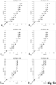
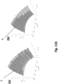
- Surfaces 5(a), 5(b) and 5(c) shown in Figure 11a identify the location of the grey rhombuses of Figure 8 , Figure 9 , and Figure 10 , respectively. It is of note that in Figures 8a to 10 , the arrows represented there, which connect the white circles, the black squares and the grey rhombuses to each other only provide for a visual indication of the order wherein the points of the three-dimensional mathematical space 3 are explored.
- the exploration of the aforementioned points requires that within a single plane of three-dimensional mathematical space 3 (represented by one of the six frame of each Figure), only one of the coordinates varies at a time, along a single direction for exploration, as described above, between a selected point and the next one.
- the points of the exploration field 4 are always explored starting from the one with lower coordinates (closest to the origin of the axes - Figures 8a , 9 and 10 ).
- the values of all three coordinate components change between the last point of a plane and the first point of the adjacent plane.
- step C comprise the execution of step D wherein a mathematical model is determined, for example by means of the data control and processing unit, in the three-dimensional mathematical space 3, the mathematical model describing in analytic form the locus of the points P* n thus stored, thereby obtaining a locus 5 of the operational parameters which determine a response in the inductor 2 which compiles with the working limit condition.
- a mathematical model is determined, for example by means of the data control and processing unit, in the three-dimensional mathematical space 3, the mathematical model describing in analytic form the locus of the points P* n thus stored, thereby obtaining a locus 5 of the operational parameters which determine a response in the inductor 2 which compiles with the working limit condition.
- step D of method 1 includes the application of at least one algorithm, for example of Genetic programming algorithm ( J. R. Koza, Genetic Programming: On the Programming of Computers by Means of Natural Selection, MIT Press, Cambridge, 1992 ), to above mentioned points P* n stored during the previous step.
- Genetic programming algorithm J. R. Koza, Genetic Programming: On the Programming of Computers by Means of Natural Selection, MIT Press, Cambridge, 1992
- P* n stored during the previous step.
- more than one algorithm belonging to the Genetic programming family of algorithms can be used for the execution of step D of the method according to the present invention.
- a Cartesian Genetic Programming algorithm J.F.
- step D of method 1 of the present invention the aforementioned algorithm is applied to the points P* n i.e., to the grey rhombuses of Figure 11a whose coordinates have been stored in the storage unit.
- the method 1 of the invention does not require the exhaustive execution of experimental tests on an entire mathematical space or three-dimensional domain of the values of the operational quantities ⁇ V eq , f sw , I L ⁇ , but only on a very reduce subset of their combinations.
- the exploration field 4 included 10 samples for each of the operational quantities ⁇ V eq , f sw , I L ⁇ , compared to 1000 possible combinations (points P n ), the method of the present invention would test about 200 points.
- a Genetic Programming algorithm that can be advantageously used in the invention method 1 can be developed ad hoc or provided by software widely used in the field, for example MatLAB.
- the tree that represents the mathematical model that is automatically generated by the Genetic Programming algorithm, providing as input a given set of elementary functions that operate on constant coefficients ( c 1 , c 2 e c 3 ) and independent variables ( x 1 and x 2 ).
- the pair of input variables ( x 1 , x 2 ) can be associated, through the data control and processing unit referred to above, to any pair of the above operational parameters ((V eq , f sw ), (f sw , I L ) or (V eq , I L ), while the output can be associated with the remaining third operational parameter.
- the coefficients and independent variables identify the terminal nodes of the tree.
- the elementary functions identify the non-terminal nodes of the tree.
- the independent variables are the inputs to the model.
- the model output is the result of the sequence of operations defined by the elementary functions.
- Table 1 reports an exemplary, non-limiting list of possible elementary functions.
- a complexity index is associated with each elementary function, as indicated in Table 1 by way of a non-limiting example.
- the input variables are assigned a complexity index of 1.
- the complexity of the model is obtained as follows:
- the Genetic programming algorithm J. R. Koza, Genetic Programming: On the Programming of Computers by Means of Natural Selection, MIT Press, Cambridge, 1992 ) which can be advantageously implemented in the method of the present invention, once the model to be generated (M.1, ..., M.9) has been determined, operates for example on a population of at least 100 models, optionally 500 models, which evolve over time over at least 100 generations, optionally 300 generations.
- Each model is a combination of elementary functions and coefficients, represented by a tree with a number of nodes not exceeding 100 nodes, optionally not exceeding 50 nodes.
- each generation the precision with which each model reproduces the reference data is evaluated, and the population is then replaced by a new generation by applying a selection operator (in particular the binary tournament operator), of a cross-over operator (in particular the subtree cross-over operator) and of a mutation operator (in particular the subtre¬e mutation operator), with equal cross-over probability of 80%, probability of subtree mutation equal to 18% and probability of node mutation equal to 2%.
- a selection operator in particular the binary tournament operator
- a cross-over operator in particular the subtree cross-over operator
- a mutation operator in particular the subtre¬e mutation operator
- models M.1, ..., M.9 consists in the fact that they allow putting into relation the operational parameters of an inductor in a direct and simpler way than traditional methods and verifying whether or not they meet certain response conditions.
- model M.1 given V eq , f sw and I L , and given the function f Veq,Pd (f sw ,I L ) corresponding to a certain P d,ref , graphically represented by surface 5, if V eq ⁇ f Veq,Pd (f sw ,I L ) then P d ⁇ P d,ref .
- the model obtained according to the method of the present invention (for example f Veq,Pd (f sw ,I L )) is defined on the samples of the surface it represents, for the identification of which few samples are sufficient, and which can be identified starting from the acquired experimental data limited to a neighbourhood thereof, in other words, without necessarily having to subject the inductor 2 to operational conditions which would determine a response very far from a limit operational condition of interest, of the type described above.
- the method 1 of the present invention can be advantageously implemented by a measuring station, indicated in Figures 12 to 17 with the reference 100, which is also the object of the present invention.
- Such a measuring station 100 configured for the implementation of method 1 of the invention, includes:
- the remote processing unit 200 can in turn be configured to apply at least one algorithm, optionally a Genetic Programming algorithm, to the finite set of such points P* n received by the measuring station 100 and output a description in analytical form of the locus of such points P* n , thus obtaining the locus 5 of the operational parameters which determine a response in the inductor 2 under investigation that complies with at least one working limit condition.
- at least one algorithm optionally a Genetic Programming algorithm
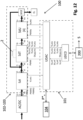
- the data control and processing unit 101 can be physically distributed among several units, for example it can comprise a first data acquisition and control unit, optionally digital, indicated with the abbreviation UDAC in Figure 12 , and another data connection unit, indicated by the abbreviation UDCD in Figure 12 , also optionally digital, configured to connect the measuring station 100 according to the invention, for example to the remote processing unit 200 where it is physically performed the algorithm, optionally of Genetic Programming, which outputs the aforementioned description in analytical form of the locus of said stored P*n points.
- a first data acquisition and control unit optionally digital, indicated with the abbreviation UDAC in Figure 12
- another data connection unit indicated by the abbreviation UDCD in Figure 12
- the algorithm optionally of Genetic Programming
- the data control and processing unit 101 can be configured to directly apply the above algorithm to the finite set of points stored in the storage 104, providing in output a description in analytical form of the locus of said points P* n thus stored, and thus obtaining the locus 5 of the operational parameters which determine a response in the inductor 2 under investigation which comply with at least one working limit condition.
- the data control and processing unit 101 is configured to handle (through a firmware stored therein) steps A to C of method 1 of the present invention, namely:
- the stimulus generation device 102 is advantageously obtained through three power converting stages operatively connected in cascade according to the so-called Opposition Method (for example as taught in F. Forest et al., "Use of opposition method in the test of high-power electronic converters," in IEEE Transactions on Industrial Electronics, vol. 53, no. 2, pp. 530-541, April 2006 ), in order to subject inductor 2 under investigation to a stimulus corresponding to a triplet of the operational conditions described above.
- Opposition Method for example as taught in F. Forest et al., "Use of opposition method in the test of high-power electronic converters," in IEEE Transactions on Industrial Electronics, vol. 53, no. 2, pp. 530-541, April 2006
- the stimulus comprises a zero mean square wave voltage, typical of hard-switching dc-dc PWM power converters, and a direct current, the characteristics of which, according to the present invention, are set by means of such converter stages.
- the three power converter stages comprise an Input Stage Sdl, a Test Stage SdT and an Output Stage SdU, wherein the Test Stage SdT is connected between the Input Stage Sdl and the Output stage SdU and is further configured to be connected to the inductor 2 to be investigated.
- the Output Stage SdU is configured to operate in a closed loop and impose a direct current at the output of the Test Stage SdT, by adjusting its own average input current I o : the SdU, therefore, operates as a variable direct current electrical load for SdT.
- the output of the Output Stage SdU is therefore connected to the input of the Test Stage SdT, so that the output current of SdU is returned to the input of SdT, so as not to make it strictly necessary, but optional, the inclusion of a power dissipating element (load EL in Figure 12 ), required to absorb the power that the SDT must deliver at the operational conditions to which the inductor 2 is subjected. In practice, this translates into a significant reduction in the power required for the operation of the measuring station.
- a switching element (Single Pole Double Throw or SPDT) of the output current can be provided, towards the SdT input or towards the external load EL, to allow in the latter case the measuring station 100 to operate even at different conditions, not foreseen in the case in which the Test Stage SdT is connected in a closed loop with the Output Stage.
- SPDT Single Pole Double Throw
- the Input Stage Sdl is configured to work in closed loop and provide in input to the Test Stage SdT one direct voltage, through adjustment of its output voltage V i
- the Test stage SdT is configured to work in open loop and provide for the switching frequency of the varying over time zero mean square wave voltage v L (t), through adjustment of its own frequency f t and duty cycle Dt.
- the Test Stage modulates the direct voltage which is imposed by the Input Stage Sdl with the direct current I L which is imposed on it by the Output stage SdU and therefore imposes to the terminals of the inductor 2 connected thereto the stimulus above described, comprising a varying over time square wave voltage v L (t) as described above and a direct current I L .
- the above adjustments are made based on specific control signals emitted by the data control and processing unit 101, according to a temporal sequence determined by an algorithm (firmware) which is stored in the data control and processing unit 101 or is supplied to it, by means of another processing unit, even a remote one (for example 200 in Figure 12 ).
- an algorithm firmware which is stored in the data control and processing unit 101 or is supplied to it, by means of another processing unit, even a remote one (for example 200 in Figure 12 ).
- the data control and processing unit 101 which can be optionally based on a micro controller, is configured to supply digital signals PWMi1, PWM2, PWMt and PWMu to stages Sdl, SdT and SdU, based on analog reference values V i,ref e I o,ref , f t,ref and D t,ref,, received from the outside or from storage unit 104 and correlated to the coordinates of points P* n previously stored therein, or from remote unit SI.
- the detecting device 103 of the measuring station 100 is integrated in the stimulus generation device 102 and is therefore also advantageously obtained through the Input Stage Sdl, Test Stage SdT and Output Stage SdU.
- the detecting device 103 comprises respective sensors, configured to supply the actually measured signal of the input current I o,mis of the SdU (corresponding to the mean value I L,av of current i L (t) represented in Figure 1 , for method 1) to the data control and processing unit 101 (more particularly to its acquisition and control unit UDAC) .
- those sensors are configured to send to the data control and processing unit 101 also a measured signal of the output voltage V i,mis of Sdl (which is one of the elements that help define the voltage v L (t) of method 1 - in particular the component V Lr of v L (t) corresponds to the difference between Vi (output voltage of the Sdl) and Vo (output voltage of SdT), while V Lf of v L (t) corresponds to the opposite of Vo (reference is always made to Figure 12 ) and of the frequency f t,mis , duty cycle D t,mis , peak-to-peak current D iLppt,mis and surface temperature T s,mis of the inductor 2 connected to the Test Stage SdT.
- V i,mis of Sdl which is one of the elements that help define the voltage v L (t) of method 1 - in particular the component V Lr of v L (t) corresponds to the difference between Vi (output voltage of the Sdl)
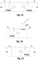
- the Input Stage Sdl can be implemented by means of a noninverting step-up-down (buck-boost) DC-DC converter with four synchronous rectification switches.
- the Sdl can use two distinct signals, PWMi1 and PWMi2, to control step-up and step-down operation, respectively.
- PWMi1 signal is active, the duty cycle Di1 of which being adjustable through a firmware implementing a first Digital Linear Controller (CLDi1), while PWMi2 signal is set to 0.
- PWMi2 signal is active, the duty cycle Di2 of which being adjustable through a firmware that implements a second Digital Linear Controller (CLDi2), while PWMi1 signal is set to 1.
- the Test Stage ( Figure 14 ) can be implemented through a step-down (buck) DC-DC converter with synchronous rectification.
- the Test stage comprises (see, in particular, Figures 16 and 17 ):
- the positioning system 107 comprises:
- the elastic anchoring group 1072 comprises one couple of elastically charged screws 10721, configured for being screwed on said printed circuit 105, passing through suitable openings obtained in said positioning plates 1071.
- the inductor 2 is configured to be placed between the printed circuit 105 and the positioning plate 1071 and to be subjected to a pressure towards the conductive tracks 106 of the printed circuit 105, by means of the elastic anchoring group 1072 thus realizing with them an electrical contact.
- one of the aforementioned sensors (not shown in the drawings) is also provided, configured to detect and transmit the surface temperature T s,mis of the inductor 2 under investigation to the data control and processing unit 101.
- the surface portion 1061 of the conductive tracks 106 has a polygonal configuration, optionally a trapezoidal one, which allows electrically and easily connecting inductors 2 of various sizes to the conductive tracks 106 of the measuring station 100, without the need for welding.
- this architecture for the measuring station 100 of the present invention, is many. First of all, it does not require a dissipative load at the output of the SdU output stage and this therefore allows its dimensions to be reduced to a minimum. It also reduces the power that the Input Stage must deliver, equal to the sum of the losses of the SdT and SdU and allows the use of a low power AC / DC mains power supply (see Figure 12 ), for example a standard rectifier, which must in fact deliver a power equal to the sum of the losses of the three Sdl, SdT and SdU stages.
- the aforementioned Input Stage Sdl can be designed in such a way as to have:
- the Test Stage SdT can be designed to have:
- the Output Stage SdU can be designed to have:
- the measuring station 100 described above, according to a variant of the invention and as anticipated above, can be used in conjunction with a remote processing unit 200, in a system 1000 for the implementation of method 1 of the present invention.
- the measuring station 100 and the remote processing unit 200 can be operationally connected through a data network, optionally via cable or wirelessly.
- System 1000 is configured for carrying out the method 1 of the present invention on the power inductors 2 which operate in typical conditions of hard-switching dc-dc PWM power converters, according to a suitable sequence of operational parameters given by the invention method 1.
- System 1000 according to a preferred embodiment of the invention, comprises:
- the architecture of system 1000 of the present invention is conceived as an open laboratory, which can be used by a single user or by a community of users and managed by an administrator.
- the software architecture can envisage three distinct types of remote processing units 200: one that operates as a System Administration (IAS), one that manages the actual execution of the measurement tests (AGE - the algorithm for determining the locus of the points of the three-dimensional mathematical space 3 that comply with the limit condition is physically executed on this unit) and a System Brokerage or Routing Unit (UBS), as illustrated in Figure 18 .
- IAS System Administration
- AGE the algorithm for determining the locus of the points of the three-dimensional mathematical space 3 that comply with the limit condition is physically executed on this unit
- UBS System Brokerage or Routing Unit
- system 1000 two operational modes are provided in system 1000:
- this can work according to a:
- the locus 5 of those operational parameters can be used by an operator, through the measuring station 100 or the system 1000 described above, to determine (for example visually by means of a display which can be operatively connected to such measuring station 100 or to a component of such system 1000) if starting from a triplet of operational parameters of the inductor under investigation, such inductor 2 complies or not with a limit condition.
- one or more mobile devices can be connected to the measuring station or system 1000, for example through the wifi, for displaying the results obtained by the method described above.
- the present invention has been described with particular reference to power inductors, it is quite clear that it can also be applied to other electronic power components such as power capacitors, taking into account that where in this text reference is made to the voltage one should instead refer to the current and vice versa, and that where in this text reference is made to the inductance L one should instead refer to the capacitance C.
- the stimulus applied to the capacitor during step C.2 of method 1 would comprise a given square wave current ic(t), varying over time, and an average voltage V C,av and the response measured at step C.3 would comprise a varying over time voltage v C (t), detected at the terminals of the same capacitor.
- corresponding response parameters at step C.4 would be determined comprised between the voltage ripple ⁇ v Cpp , the surface temperature T s of the capacitor, and the average electrical power P d dissipated by the capacitor.
Landscapes
- Physics & Mathematics (AREA)
- General Physics & Mathematics (AREA)
- Engineering & Computer Science (AREA)
- Power Engineering (AREA)
- Measurement Of Current Or Voltage (AREA)
- Testing Electric Properties And Detecting Electric Faults (AREA)
- Arrangements For Transmission Of Measured Signals (AREA)
Claims (26)
- Verfahren (1) zur Bestimmung des Verhaltens eines elektrischen oder elektronischen Leistungsbauteils (2) in Bezug auf einen Arbeitsgrenzzustand, wobei das Verfahren die folgenden Arbeitsschritte umfasst:A. Definieren eines dreidimensionalen mathematischen Raums (3) von Betriebsparametern, die für das elektrische oder elektronische Leistungsbauteil (2) von Interesse sind, wobei die Koordinaten eines n-ten Punktes P des dreidimensionalen mathematischen Raums (3) spezifischen Werten der Betriebsparameter entsprechen, die für das elektrische oder elektronische Leistungsbauteil (2) von Interesse sind;B. Definieren eines Erkundungsfeldes (4) des dreidimensionalen mathematischen Raums (3), der Arbeitsgrenzbedingung für das elektrische oder elektronische Leistungsbauteil (2) und eines Satzes R von interessierenden Antwortparametern für das elektrische oder elektronische Leistungsbauteil (2);
gekennzeichnet durch die folgenden zusätzlichen Arbeitsschritte:C. untersuchen des dreidimensionalen mathematischen Raumes (3) durch:- Erzeugung mindestens einer Anregung, der auf der Grundlage der Koordinaten der Punkte Pn des dreidimensionalen mathematischen Raums (3) und des Erkundungsfelds (4) bestimmt wird,- Anwendung des mindestens einen Anregung auf das mindestens eine elektrische oder elektronische Leistungsbauteil (2) und- Erfassen einer entsprechenden Reaktion auf die dadurch angelegte Anregung von dem elektrischen oder elektronischen Leistungsbauteil (2), undBestimmen und Speichern einer endlichen Untermenge von Punkten P*n des dreidimensionalen mathematischen Raums (3) unter den Punkten Pn des dreidimensionalen mathematischen Raums (3), für die die Arbeitsgrenzbedingung das elektronischen Leistungsbauteil (2) erfüllt ist, basierend auf der dadurch erfassten Antwort; undD. Bestimmen eines mathematischen Modells, das den Ort der Punkte P*n des dreidimensionalen mathematischen Raums (3) analytisch beschreibt, der auf diese Weise gespeichert wird, um so den Ort (5) der Betriebsparameter zu erhalten, die eine Reaktion des elektrischen oder elektronischen Leistungsbauteils (2) bestimmen, die die Arbeitsgrenzbedingung erfüllt. - Verfahren (1) nach Anspruch 1, wobei die interessierenden Betriebsparameter für das elektrische oder elektronische Leistungsbauteil (2) ausgewählt werden aus:eine Ersatzspannung (Veq), die an das elektrische oder elektronische Leistungsbauteil (2) anzulegen ist;- eine Schaltfrequenz (fsw) für einen gesamten Lade-Entlade-Zyklus des elektrischen oder elektronischen Leistungsbauteils (2);einen durchschnittlichen Strom (IL), der durch das elektrische oder elektronische Leistungsbauteil (2) fließt; und- eine Temperatur (Ta) der Umgebung, in der das elektrische oder elektronische Leistungsbauteil (2) in Betrieb ist.
- Verfahren (1) nach Anspruch 1 oder 2, wobei der dreidimensionale mathematische Raum (3) definiert wird, indem jedem der interessierenden Betriebsparameter des elektrischen oder elektronischen Leistungsbauteils (2) eine entsprechende mathematische Achse eines euklidischen dreidimensionalen mathematischen Raums zugewiesen wird.
- Verfahren (1) nach einem der vorhergehenden Ansprüche, wobei das mindestens eine Erkundungsfeld (4) durch Auswahl definiert wird:eine endliche Untermenge von Punkten Pn des dreidimensionalen mathematischen Raums (3); undeine geordnete Menge von drei Erkundungsrichtungen der Punkte des Erkundungsfeldes (4), ausgehend von einem beliebigen Punkt Pn-1 zu einem nächsten Punkt Pn, wobei jede Erkundungsrichtung gegebenenfalls parallel zu einer entsprechenden Achse des dreidimensionalen mathematischen Raums (3) verläuft.
- Verfahren nach Anspruch 4, bei dem die Erkundung des dreidimensionalen mathematischen Raums (3) ausgehend von einem Startpunkt Pn des Erkundungsfelds (4) entlang der Erkundungsrichtungen in geordneter Weise und gemäß einer Erkundungsregel derart durchgeführt wird, dass sich die Koordinaten eines erkundeten n-ten Punkts Pn des dreidimensionalen mathematischen Raums (3) von denen eines vorherigen Punkts Pn-1 für den Wert einer oder mehrerer seiner Komponenten unterscheiden.
- Verfahren nach Anspruch 4 oder 5, bei dem die Koordinaten (pn1, pn2, pn3) der Punkte Pn des Erkundungsfeldes (4) Werte aufweisen, die zwischen einem Minimalwert und einem Maximalwert der jeweiligen Betriebsparameter (Veq, fsw, IL) liegen, und bei dem die endliche Anzahl der Punkte P des Erkundungsfeldes (4) für jede der Erkundungsrichtungen des dreidimensionalen mathematischen Raumes eine Funktion ist von:- eine Anzahl von Stichproben (NVeq, Nfsw, NIL); und- einen Versatz (ΔVeq, Δfsw, ΔIL) zwischen einer Probe und der nächsten entlang der jeweiligen Erkundungsrichtung.
- Verfahren nach Anspruch 6, bei dem für jede Richtung der genannten Erkundungsrichtungen:die Anzahl der Proben (NVeq, Nfsw, NIL) fest ist und der Offset (ΔVeq, Δfsw, ΔIL) fest und konstant ist; oderdie Anzahl der Proben (NVeq, Nfsw, NIL) ist fest, und der Offset (ΔVeq,i, Δfsw,j, ΔIL,k) zwischen zwei aufeinanderfolgenden Abtastwerten variiert, wahlweise entsprechend einer Funktion, die aus einer vorgegebenen logarithmischen, Potenz-, trigonometrischen, transzendenten odernumerischen Reihenfunktion ausgewählt werden kann; oder- die Anzahl der Proben (NVeq, Nfsw, NIL) von einem Offset (ΔVeq,i, Δfsw,j, ΔIL,k) abhängt, der während der Erkundung des Erkundungsfeldes (4) für jeden Punkt Pn gegebenenfalls auf der Grundlage eines Wertes eines Satzes R von Antwortparametern berechnet wird, wobei die Antwortparameter an den beiden letzten in dem Erkundungsfeld (4) erkundeten Punkten Pn-1 ; Pn-2 berechnet werden.
- Verfahren (1) nach einem der vorhergehenden Ansprüche, bei dem die Einhaltung oder Nichteinhaltung der Arbeitsgrenzbedingung in einem beliebigen Punkt Pn des dreidimensionalen mathematischen Raums (3) vom Wert mindestens eines Antwortparameters des Satzes R von Antwortparametern des elektrischen oder elektronischen Leistungsbauteils (2) abhängt, wobei die Antwortparameter auf der Grundlage der von des elektrischen oder elektronischen Leistungsbauteils (2) nach dem Anlegen der Anregung an ihre Anschlüsse erfassten Antwort und einer voreingestellten Suchlogik bestimmt werden.
- Verfahren (1) nach Anspruch 8, wobei der Ansprechparameter des Satzes R von Ansprechparametern des elektrischen oder elektronischen Leistungsbauteils (2) einer der folgenden ist:- eine Spitze-Spitze-Schwankung (iΔLpp) eines Stroms (iL(t)), der sich im Laufe der Zeit ändert und durch das elektrische oder elektronische Leistungsbauteil (2) fließt;- eine Oberflächentemperatur (TS) des elektrischen oder elektronischen Leistungsbauteils (2);- eine durchschnittliche elektrische Leistung (Pd), die von dem elektrischen oder elektronischen Leistungsbauteil (2) abgegeben wird.
- Verfahren (1) nach Anspruch 8 oder 9, wobei die Arbeitsgrenzbedingung des elektrischen oder elektronischen Leistungsbauteils (2) eine Funktion eines vordefinierten Schwellenwerts (ΔiLpp,ref , Ts,ref, Pd,ref) für jeden Reaktionsparameter ist.
- Verfahren (1) nach Anspruch 10, wobei der mindestens eine Antwortparameter mit der mindestens einen Arbeitsgrenzbedingung übereinstimmt, wenn sein Wert kleiner oder gleich einem entsprechenden Schwellenwert (Δi Lpp,ref , Ts,ref, Pd,ref) ist
- Verfahren (1) nach einem der vorhergehenden Ansprüche, wobei der Schritt C umfasst:C.1Auswahl eines Startpunktes Pn durch eine Datensteuerungs- und-verarbeitungseinheit (101) die in dem Erkundungsfeld (4) enthalten sind, und eine erste Erkundungsrichtung des Erkundungsfeldes (4);C.2 Erzeugen einer Anregung durch eine Anregung -Erzeugungsvorrichtung, der eine über die Zeit variierende Spannung vL(t) und einen konstanten Durchschnittsstrom IL umfasst, basierend auf dem Wert der Koordinaten des soeben ausgewählten Punktes Pn, und Anlegen der so erzeugten Anregung an die Klemmen des elektrischen oder elektronischen Leistungsbauteils (2);C.3 Erfassen an den Anschlüssen des elektrischen oder elektronischen Leistungsbauteils (2) durch eine Erfassungsvorrichtung als Antwort auf die dadurch angelegte Anregung mindestens einen entsprechenden Strom (iL(t)), der sich über die Zeit ändert und durch das elektrische oder elektronische Leistungsbauteil (2) fließt, und eine entsprechende Oberflächentemperatur (TS);C.4 Bestimmen des Satzes R von Reaktionsparametern durch die Datensteuerungs- und - verarbeitungseinheit (101) auf der Grundlage des Stroms (iL(t)) und der dadurch erfassten Oberflächentemperatur (TS); undC.5 Vergleichen jedes Elements des Satzes R von Ansprechparametern mit der Arbeitsgrenzbedingung durch die Datensteuerungs- und-verarbeitungseinheit (101); undC.6 wenn die Bedingung der Arbeitsgrenze an diesem Punkt erfüllt ist:C.6.1 Auswahl eines neuen Punktes Pn des dreidimensionalen mathematischen Raums (3) entlang des erste gewählte Erkundungsrichtung; undC.6.2 wenn der Punkt Pn innerhalb des Erkundungsfeldes (4) liegt, zurück zu Schritt C.2; ansonsten weiter zu Schritt C.8C.7 wenn die Bedingung der Arbeitsgrenze an diesem Punkt Pn nicht erfüllt ist:C.7.1 wenn der soeben ausgewählte Punkt Pn der Anfangspunkt des Erkundungsfeldes (4) ist:C.7.1.1 Auswahl eines neuen Punktes Pn des dreidimensionalen mathematischen Raumes (3),entlang der genannten ersten ausgewählten Erkundungsrichtung;
UndC.7.1.2 wenn der neue Punkt Pn innerhalb des Erkundungsfeldes (4) enthalten ist:C.7.1.2.1 Durchführung der Schritte C.2-C.5 undC.7.1.2.2 wenn die Bedingung der Arbeitsgrenze in dem neuen Punkt Pn nicht erfüllt ist.zurück zu Schritt C.7.1.1,Andernfalls kehren Sie zu Schritt C.6 zurück;ansonsten weiter zu Schritt C.8ansonstenC.7.2 wenn der soeben ausgewählte Punkt Pn und der davor liegende Punkt Pn-1 entlang der ersten Erkundungsrichtung liegen:C.7.2.1 Bestimmen und Speichern durch die Datensteuerungs- und-verarbeitungseinheit (101),in einer Speichereinheit die Koordinaten (p*n1, p*n2, p*n3) eines anderen Punktes P*n der Drei- dimensionalen Raum 3, der in der Nachbarschaft des Punktes Pn des Erkundungsfeldes (4) entlang der ersten gewählten Erkundungsrichtung enthalten ist, wobei die Bedingung der Arbeitsgrenze erfüllt ist;C.7.2.2 Auswählen des Punktes Pn-1 vor dem Pn und, ausgehend davon, eines neuen Punktes Pn entlang der zweiten Erkundungsrichtung; undC.7.2.3 wenn der neu ausgewählte Punkt Pn innerhalb des Erkundungsfeldes (4) liegt, Rückkehr zu Schritt C.2;ansonsten weiter zu Schritt C.8ansonstenC.7.3 wenn der soeben ausgewählte Punkt Pn und der davor liegende Punkt Pn-1 entlang der zweiten Erkundungsrichtung liegen:C.7.3.1 Auswählen eines neuen Punktes Pn des dreidimensionalen mathematischen Raums (3) entlang der ersten ausgewählten Erkundungsrichtung; undC.7.3.2 wenn der neu ausgewählte Punkt Pn innerhalb des Erkundungsfeldes (4) liegt, Rückkehr zu Schritt C.2;ansonsten weiter zu Schritt C.8C.8, wenn der soeben ausgewählte Punkt Pn nicht in dem Erkundungsfeld (4) liegt:C.8.1 Auswählen eines neuen Punktes Pn des dreidimensionalen mathematischen Raums (3) entlang der zweiten Erkundungsrichtung, ausgehend von dem zuvor ausgewählten Punkt Pn-1, und, wenn der neu ausgewählte Punkt Pn in dem Erkundungsfeld (4) enthalten ist, Zurückgehen zum Schritt C.2; andernfallsC.8.2 Auswählen eines neuen Punktes Pn des dreidimensionalen mathematischen Raums (3) entlang der dritten Erkundungsrichtung, ausgehend von dem zuvor ausgewählten Punkt Pn-1, und, wenn der neu ausgewählte Punkt Pn in dem Erkundungsfeld (4) enthalten ist, Zurückgehen zum Schritt C.2; andernfalls Gehen zum Schritt D des Verfahrens. - Verfahren (1) nach Anspruch 12, bei dem die gespeicherten Koordinaten des Punktes P*n des mathematischen Raums (3), der in der Nachbarschaft des Punktes Pn des Erkundungsfeldes (4) liegt, durch eine Interpolationsformel, gegebenenfalls eine lineare, berechnet werden.
- Verfahren (1) nach einem der vorhergehenden Ansprüche, wobei der Schritt D darin besteht, auf die Punkte P*n des mathematischen Raums (3), der dadurch gespeichert wird, über die Datensteuerungs- und-verarbeitungseinheit (101) mindestens einen Algorithmus der genetischen Programmierung oder der grammatikalischen Evolution anzuwenden.
- Messplatz (100), konfiguriert zur Durchführung des Verfahrens (1) zur Bestimmung des Verhaltens eines elektrischen oder elektronischen Leistungsbauteils (2) nach einem der vorhergehenden Ansprüche, umfassend:- eine Datensteuerungs- und -verarbeitungseinheit (101), die so konfiguriert ist, dass sie den dreidimensionalen mathematischen Raum (3), das Erkundungsfeld (4), die Arbeitsgrenzbedingung und den Satz R von Antwortparametern definiert und jedes Element des Satzes R, das für die erkundeten Punkte des dreidimensionalen mathematischen Raums (3) bestimmt wurde, mit der Arbeitsgrenzbedingung vergleicht;- eine Anregung -Erzeugungsvorrichtung (102), die operativ mit der Datensteuerungs-und-verarbeitungseinheit (101) verbunden ist und so konfiguriert ist, dass sie mindestens eine Anregung erzeugt, wobei die Anregung mindestens eine Nullmittel- und Rechteckspannung vL(t) und einen konstanten Durchschnittsstrom IL für das elektrische oder elektronische Leistungsbauteil (2) umfasst, auf der Grundlage des Wertes der Koordinaten des Punktes Pn des dreidimensionalen mathematischen Raums (3), wobei die Koordinaten den jeweiligen Werten der Betriebsparameter (Veq, fsw, IL) des elektrischen oder elektronischen Leistungsbauteils (2) zugeordnet sind, und um die so erzeugte Anregung auf das elektrische oder elektronische Leistungsbauteil (2) anzuwenden;- eine Erfassungsvorrichtung (103), die operativ mit der Datensteuerungs-und-verarbeitungseinheit (101) verbunden ist und so konfiguriert ist, dass sie den mindestens einen sich über die Zeit verändernden Strom iL(t) und eine Oberflächentemperatur Ts des elektrischen oder elektronischen Leistungsbauteils (2) als Antwort auf die dadurch angelegte Anregung erfasst;- mindestens eine Speichereinheit (104), die operativ mit der Datensteuerungs-und-verarbeitungseinheit (101) verbunden und zum Speichern der Koordinaten der Punkte P*n des mathematischen Raums (3) konfiguriert ist, in dem die Arbeitsgrenzbedingung erfüllt ist;wobei die Datensteuerungs-und-verarbeitungseinheit (101) so konfiguriert ist, dass sie auf die Koordinaten der dadurch gespeicherten Punkte P*n mindestens einen mathematischen Algorithmus, optional einen Algorithmus der genetischen Programmierung oder der grammatikalischen Evolution, anwendet, wobei der mindestens eine mathematische Algorithmus am Ausgang eine Beschreibung in analytischer Form der Ortskurve der Punkte P*n und somit der Ortskurve (5) der entsprechenden Betriebsparameter liefert, die eine Reaktion des elektrischen oder elektronischen Leistungsbauteils (2) bestimmen, die die mindestens eine Arbeitsgrenzbedingung erfüllt.
- Messplatz (100) nach Anspruch 15, wobei die eine Anregung erzeugende Vorrichtung (102) und die Erfassungsvorrichtung (103) werden durch drei Leistungswandlerstufen erhalten, die gemäß einem Oppositionsverfahren in Kaskade geschaltet sind, um:- die mindestens eine elektrische oder elektronische Leistungskomponente (2) dem mindestens eine Anregung unterwirft, basierend auf dem Wert der Koordinaten des Punktes Pn; und- mindestens einen über die Zeit variierenden Strom iL(t) und eine Oberflächentemperatur T des elektrischen oder elektronischen Leistungsbauteils (2) zu erfassen.
- Messplatz (100) nach Anspruch 15 oder 16, wobei die drei Wandler eine Eingangsstufe (Sdl), eine Teststufe (SdT) und eine Ausgangsstufe (SdU) umfassen, wobei die Teststufe (SdT) zwischen die Eingangsstufe (Sdl) und die Ausgangsstufe (SdT) geschaltet ist und ferner so konfiguriert ist, dass sie mit dem elektrischen oder elektronischen Leistungsbauteil (2) verbunden ist.
- Messplatz (100) nach Anspruch 17, die stromabwärts der Ausgangsstufe (SdU) ein Schaltelement (SPDT) für den von der Ausgangsstufe (SdU) ausgegebenen Strom in Richtung des Eingangs der Teststufe (SdT) oder einer externen Last (EL) umfasst.
- Messplatz (100) nach Anspruch 17 oder 18, wobei die Eingangsstufe (Sdl) so konfiguriert ist, dass sie in einer geschlossenen Schleife arbeitet und am Eingang der Teststufe (SdT) eine Gleichspannung durch Einstellung ihrer Ausgangsspannung (Vi) bereitstellt, und wobei die Teststufe (SdT) so konfiguriert ist, dass sie in einer offenen Schleife arbeitet und eine Schaltfrequenz der Nullmittel- und Rechteckspannung VL(t) durch Einstellung ihrer eigenen Frequenz (ft) und ihres Tastverhältnisses (Dt) bereitstellt.
- Messplatz (100) nach einem der Ansprüche 17 bis 19, wobei die Ausgangsstufe (SdU) so konfiguriert ist, dass sie im geschlossenen Regelkreis arbeitet und am Ausgang der Teststufe (SdT) einen Gleichstrom durch Einstellung ihres eigenen durchschnittlichen Eingangsstroms erzeugt.
- Messplatz (100) nach einem der Ansprüche 15 bis 20, umfassend:- eine gedruckte Schaltung (105) mit leitenden Pfaden (106), die so konfiguriert sind, dass sie die Anregung auf das elektrische oder elektronische Leistungsbauteil (2) ausüben, wobei die leitenden Pfade (106) mindestens einen Oberflächenabschnitt (1061) aufweisen, der so konfiguriert ist, dass er mit des elektrischen oder elektronischen Leistungsbauteils (2) in elektrischen Kontakt tritt; und- ein Positionierungssystem (107) für das elektrische oder elektronische Leistungsbauteil (2) und die gedruckte Schaltung (105), wobei das elektrische oder elektronische Leistungsbauteil (2) in elektrischem Kontakt mit den Leiterbahnen (106) der gedruckten Schaltung (105) steht, ohne dass Schweißnähte erforderlich sind.
- Messplatz (100) nach Anspruch 21, wobei das Positionierungssystem (107) umfasst:- eine Positionierungsplatte (1071) und- eine Gruppe (1072) für die elastische Verankerung der Positionierungsplatte (1071) an der gedruckten Schaltung (105); wobei das elektrische oder elektronische Leistungsbauteil (2) so konfiguriert ist, dass es zwischen der gedruckten Schaltung (105) und der Positionierungsplatte (1071) angeordnet und einem Druck ausgesetzt ist in Richtung der Leiterbahnen (106) der gedruckten Schaltung (105), durch die elastische Verankerungsgruppe (1072).
- Messplatz (100) nach Anspruch 22, wobei die elastische Verankerungsgruppe (1072) ein Paar von elastisch geladenen Schrauben (10721) umfasst, die so konfiguriert sind, dass sie in die gedruckte Schaltung geschraubt werden können, indem sie durch geeignete Öffnungen in den Positionierungsplatten (1071) geführt werden.
- Messplatz (100) nach einem der Ansprüche 21 bis 23, wobei die Leiterbahnen (106) eine polygonale, gegebenenfalls trapezförmige Konfiguration aufweisen.
- Messplatz (100) nach einem der Ansprüche 21 bis 24, wobei die Erfassungsvorrichtung (103) mindestens einen Temperatursensor umfasst, der funktionell mit der Datensteuerungs-und -verarbeitungseinheit (101) verbunden und so konfiguriert ist, dass er die Oberflächentemperatur (Ts) des elektrischen oder elektronischen Leistungsbauteils (2) erfasst und an die Datensteuerungs- und -verarbeitungseinheit (101) überträgt.
- System (1000) zur Durchführung des Verfahrens (1) zur Bestimmung des Verhaltens einer elektrischen oder elektronischen Leistungskomponente (2) nach einem der vorhergehenden Ansprüche, umfassend mindestens eine Messstation (100) nach einem der Ansprüche 15 bis 25 und mindestens eine Fernverarbeitungseinheit (200), wobei die Messstation (100) und die Fernverarbeitungseinheit (200) operativ miteinander verbunden sind, wahlweise über ein Netzwerk, wahlweise über ein Kabel oder drahtlos, und wobei die Datensteuerungs- und - verarbeitungseinheit (101) der Messstation (100) so konfiguriert ist, dass sie an die mindestens eine Fernverarbeitungseinheit (200) die Koordinaten der Punkte P*n sendet, die dadurch gespeichert werden, und die mindestens eine Fernverarbeitungseinheit (200) so konfiguriert ist, dass sie mindestens einen mathematischen Algorithmus anwendet, gegebenenfalls einen Algorithmus der genetischen Programmierung oder der grammatikalischen Evolution, anzuwenden, der am Ausgang eine Beschreibung in analytischer Form der Ortskurve der Punkte P*n und somit der Ortskurve (5) der entsprechenden Betriebsparameter liefert, die eine Antwort des elektrischen oder elektronischen Leistungsbauteils (2) bestimmen, die mindestens eine Arbeitsgrenzbedingung erfüllt.
Applications Claiming Priority (2)
| Application Number | Priority Date | Filing Date | Title |
|---|---|---|---|
| IT102020000026599A IT202000026599A1 (it) | 2020-11-06 | 2020-11-06 | Metodo, stazione di misurazione e sistema di determinazione del comportamento di un componente elettrico o elettronico di potenza |
| PCT/IB2021/060270 WO2022097086A1 (en) | 2020-11-06 | 2021-11-05 | Method, measuring station and system for determining the behaviour of one electrical or electronic power component |
Publications (2)
| Publication Number | Publication Date |
|---|---|
| EP4241094A1 EP4241094A1 (de) | 2023-09-13 |
| EP4241094B1 true EP4241094B1 (de) | 2024-10-16 |
Family
ID=74347552
Family Applications (1)
| Application Number | Title | Priority Date | Filing Date |
|---|---|---|---|
| EP21815666.9A Active EP4241094B1 (de) | 2020-11-06 | 2021-11-05 | Verfahren, messstation und system zur bestimmung des verhaltens eines elektrischen oder elektronischen leistungsbauelements |
Country Status (4)
| Country | Link |
|---|---|
| US (1) | US20230266373A1 (de) |
| EP (1) | EP4241094B1 (de) |
| IT (1) | IT202000026599A1 (de) |
| WO (1) | WO2022097086A1 (de) |
Families Citing this family (1)
| Publication number | Priority date | Publication date | Assignee | Title |
|---|---|---|---|---|
| CN121008154B (zh) * | 2025-10-27 | 2026-02-17 | 苏州元脑智能科技有限公司 | 元件性能测试方法及系统 |
Family Cites Families (7)
| Publication number | Priority date | Publication date | Assignee | Title |
|---|---|---|---|---|
| US5793640A (en) * | 1996-12-26 | 1998-08-11 | Vlsi Technology, Inc. | Capacitance measurement using an RLC circuit model |
| US6876936B2 (en) * | 2003-07-25 | 2005-04-05 | Tektronix, Inc. | Measurement of inductance using a digital storage oscilloscope under real-time operating environments |
| US7042207B1 (en) | 2003-11-07 | 2006-05-09 | National Semiconductor Corporation | Inductive measurement system and method |
| CN102818934A (zh) | 2011-06-08 | 2012-12-12 | 鸿富锦精密工业(深圳)有限公司 | 电感直流电阻测量电路 |
| BE1020014A5 (nl) * | 2012-01-27 | 2013-03-05 | Mindcet Bvba | Werkwijzen en systeem voor het berekenen van modelparameters voor een te modelleren spoel. |
| BE1022933B1 (nl) * | 2014-11-07 | 2016-10-20 | Mindcet Bvba | Werkwijze en systeem voor het berekenen van modelparameters voor een te modelleren condensator |
| US20210081592A1 (en) * | 2019-09-17 | 2021-03-18 | Tektronix, Inc. | Simulation correction using measurements and deep learning |
-
2020
- 2020-11-06 IT IT102020000026599A patent/IT202000026599A1/it unknown
-
2021
- 2021-11-05 US US18/002,618 patent/US20230266373A1/en active Pending
- 2021-11-05 WO PCT/IB2021/060270 patent/WO2022097086A1/en not_active Ceased
- 2021-11-05 EP EP21815666.9A patent/EP4241094B1/de active Active
Also Published As
| Publication number | Publication date |
|---|---|
| EP4241094A1 (de) | 2023-09-13 |
| US20230266373A1 (en) | 2023-08-24 |
| WO2022097086A1 (en) | 2022-05-12 |
| IT202000026599A1 (it) | 2022-05-06 |
Similar Documents
| Publication | Publication Date | Title |
|---|---|---|
| Rojas-Duenas et al. | Nonlinear least squares optimization for parametric identification of DC–DC converters | |
| EP4516141A1 (de) | Temperaturmessvorrichtung und -verfahren, computervorrichtung und speichermedium | |
| US10734847B2 (en) | Wireless power system with coupling-coefficient-based coil selection | |
| JP5924617B2 (ja) | 等価回路合成方法並びに装置、および回路診断方法 | |
| EP3114446B1 (de) | Verfahren und vorrichtung zur berechnung der übergangstemperatur eines rf-leistungs-mosfet | |
| JP2007082394A (ja) | 電源の調整を改善する方法及び装置 | |
| CN112798976A (zh) | 一种电源故障判断方法、设备、电子设备及存储介质 | |
| EP3672049A1 (de) | Adaptive steuerung eines geschalteten spannungswandlers | |
| EP3018813A1 (de) | Verfahren und system zur berechnung von modellparametern für einen zu modellierenden kondensator | |
| US20230266373A1 (en) | Method, measuring station and system for determining the behaviour of one electrical or electronic power component | |
| Di Nezio et al. | 3-phase boost rectifier condition health monitoring based on digital twin technique | |
| CN114417935A (zh) | 一种确定变分模态分解中分解模态数的方法、装置及设备 | |
| Huynh et al. | An experimental study of EMI reduction of DC-DC converter with frequency hopping technique | |
| KR102358109B1 (ko) | 이차전지 충방전기 고장 예측시스템 및 방법 | |
| Bréard et al. | Metamodel of power electronic converters using learning SVR method coupling with wavelet compression | |
| Foo et al. | Can higher frequencies reduce magnetics size? An exploration of the impact of frequency on optimized flyback transformers | |
| Tran et al. | Design of LC harmonic notch filter for ripple reduction in step-down dc-dc buck converter | |
| Martín et al. | Exact steady state analysis in power converters using Floquet decomposition | |
| Zhang et al. | A purely data-driven modeling method based on subspace system identification for DC-DC converters | |
| Dey et al. | Experimental Small-signal Characterization of Frequency Modulated Converters | |
| Bilberry et al. | Power supply on chip (PwrSoC) model identification using black-box modeling techniques | |
| Chao et al. | An Intelligent Fault Diagnosis Method Based on Extension Theory for DC–AC Converters | |
| CN120595084B (zh) | 一种隔离式共阴电流电路及隔离式共阴电流电路测试方法 | |
| Bishnoi et al. | EMI modeling of buck converter using a generalized terminal model | |
| Sun | Accurate modeling techniques for power delivery |
Legal Events
| Date | Code | Title | Description |
|---|---|---|---|
| STAA | Information on the status of an ep patent application or granted ep patent |
Free format text: STATUS: UNKNOWN |
|
| STAA | Information on the status of an ep patent application or granted ep patent |
Free format text: STATUS: THE INTERNATIONAL PUBLICATION HAS BEEN MADE |
|
| PUAI | Public reference made under article 153(3) epc to a published international application that has entered the european phase |
Free format text: ORIGINAL CODE: 0009012 |
|
| STAA | Information on the status of an ep patent application or granted ep patent |
Free format text: STATUS: REQUEST FOR EXAMINATION WAS MADE |
|
| 17P | Request for examination filed |
Effective date: 20221213 |
|
| AK | Designated contracting states |
Kind code of ref document: A1 Designated state(s): AL AT BE BG CH CY CZ DE DK EE ES FI FR GB GR HR HU IE IS IT LI LT LU LV MC MK MT NL NO PL PT RO RS SE SI SK SM TR |
|
| P01 | Opt-out of the competence of the unified patent court (upc) registered |
Effective date: 20231019 |
|
| DAV | Request for validation of the european patent (deleted) | ||
| DAX | Request for extension of the european patent (deleted) | ||
| GRAP | Despatch of communication of intention to grant a patent |
Free format text: ORIGINAL CODE: EPIDOSNIGR1 |
|
| STAA | Information on the status of an ep patent application or granted ep patent |
Free format text: STATUS: GRANT OF PATENT IS INTENDED |
|
| INTG | Intention to grant announced |
Effective date: 20240604 |
|
| GRAS | Grant fee paid |
Free format text: ORIGINAL CODE: EPIDOSNIGR3 |
|
| GRAA | (expected) grant |
Free format text: ORIGINAL CODE: 0009210 |
|
| STAA | Information on the status of an ep patent application or granted ep patent |
Free format text: STATUS: THE PATENT HAS BEEN GRANTED |
|
| AK | Designated contracting states |
Kind code of ref document: B1 Designated state(s): AL AT BE BG CH CY CZ DE DK EE ES FI FR GB GR HR HU IE IS IT LI LT LU LV MC MK MT NL NO PL PT RO RS SE SI SK SM TR |
|
| REG | Reference to a national code |
Ref country code: GB Ref legal event code: FG4D |
|
| REG | Reference to a national code |
Ref country code: CH Ref legal event code: EP |
|
| REG | Reference to a national code |
Ref country code: IE Ref legal event code: FG4D |
|
| REG | Reference to a national code |
Ref country code: DE Ref legal event code: R096 Ref document number: 602021020451 Country of ref document: DE |
|
| REG | Reference to a national code |
Ref country code: LT Ref legal event code: MG9D |
|
| REG | Reference to a national code |
Ref country code: NL Ref legal event code: MP Effective date: 20241016 |
|
| REG | Reference to a national code |
Ref country code: AT Ref legal event code: MK05 Ref document number: 1733313 Country of ref document: AT Kind code of ref document: T Effective date: 20241016 |
|
| PG25 | Lapsed in a contracting state [announced via postgrant information from national office to epo] |
Ref country code: NL Free format text: LAPSE BECAUSE OF FAILURE TO SUBMIT A TRANSLATION OF THE DESCRIPTION OR TO PAY THE FEE WITHIN THE PRESCRIBED TIME-LIMIT Effective date: 20241016 |
|
| PG25 | Lapsed in a contracting state [announced via postgrant information from national office to epo] |
Ref country code: NL Free format text: LAPSE BECAUSE OF FAILURE TO SUBMIT A TRANSLATION OF THE DESCRIPTION OR TO PAY THE FEE WITHIN THE PRESCRIBED TIME-LIMIT Effective date: 20241016 |
|
| PG25 | Lapsed in a contracting state [announced via postgrant information from national office to epo] |
Ref country code: IS Free format text: LAPSE BECAUSE OF FAILURE TO SUBMIT A TRANSLATION OF THE DESCRIPTION OR TO PAY THE FEE WITHIN THE PRESCRIBED TIME-LIMIT Effective date: 20250216 Ref country code: HR Free format text: LAPSE BECAUSE OF FAILURE TO SUBMIT A TRANSLATION OF THE DESCRIPTION OR TO PAY THE FEE WITHIN THE PRESCRIBED TIME-LIMIT Effective date: 20241016 Ref country code: PT Free format text: LAPSE BECAUSE OF FAILURE TO SUBMIT A TRANSLATION OF THE DESCRIPTION OR TO PAY THE FEE WITHIN THE PRESCRIBED TIME-LIMIT Effective date: 20250217 |
|
| PG25 | Lapsed in a contracting state [announced via postgrant information from national office to epo] |
Ref country code: FI Free format text: LAPSE BECAUSE OF FAILURE TO SUBMIT A TRANSLATION OF THE DESCRIPTION OR TO PAY THE FEE WITHIN THE PRESCRIBED TIME-LIMIT Effective date: 20241016 |
|
| PG25 | Lapsed in a contracting state [announced via postgrant information from national office to epo] |
Ref country code: BG Free format text: LAPSE BECAUSE OF FAILURE TO SUBMIT A TRANSLATION OF THE DESCRIPTION OR TO PAY THE FEE WITHIN THE PRESCRIBED TIME-LIMIT Effective date: 20241016 |
|
| PG25 | Lapsed in a contracting state [announced via postgrant information from national office to epo] |
Ref country code: ES Free format text: LAPSE BECAUSE OF FAILURE TO SUBMIT A TRANSLATION OF THE DESCRIPTION OR TO PAY THE FEE WITHIN THE PRESCRIBED TIME-LIMIT Effective date: 20241016 |
|
| PG25 | Lapsed in a contracting state [announced via postgrant information from national office to epo] |
Ref country code: NO Free format text: LAPSE BECAUSE OF FAILURE TO SUBMIT A TRANSLATION OF THE DESCRIPTION OR TO PAY THE FEE WITHIN THE PRESCRIBED TIME-LIMIT Effective date: 20250116 |
|
| PG25 | Lapsed in a contracting state [announced via postgrant information from national office to epo] |
Ref country code: AT Free format text: LAPSE BECAUSE OF FAILURE TO SUBMIT A TRANSLATION OF THE DESCRIPTION OR TO PAY THE FEE WITHIN THE PRESCRIBED TIME-LIMIT Effective date: 20241016 Ref country code: GR Free format text: LAPSE BECAUSE OF FAILURE TO SUBMIT A TRANSLATION OF THE DESCRIPTION OR TO PAY THE FEE WITHIN THE PRESCRIBED TIME-LIMIT Effective date: 20250117 Ref country code: LV Free format text: LAPSE BECAUSE OF FAILURE TO SUBMIT A TRANSLATION OF THE DESCRIPTION OR TO PAY THE FEE WITHIN THE PRESCRIBED TIME-LIMIT Effective date: 20241016 |
|
| PG25 | Lapsed in a contracting state [announced via postgrant information from national office to epo] |
Ref country code: PL Free format text: LAPSE BECAUSE OF FAILURE TO SUBMIT A TRANSLATION OF THE DESCRIPTION OR TO PAY THE FEE WITHIN THE PRESCRIBED TIME-LIMIT Effective date: 20241016 |
|
| PG25 | Lapsed in a contracting state [announced via postgrant information from national office to epo] |
Ref country code: RS Free format text: LAPSE BECAUSE OF FAILURE TO SUBMIT A TRANSLATION OF THE DESCRIPTION OR TO PAY THE FEE WITHIN THE PRESCRIBED TIME-LIMIT Effective date: 20250116 |
|
| REG | Reference to a national code |
Ref country code: CH Ref legal event code: PL |
|
| PG25 | Lapsed in a contracting state [announced via postgrant information from national office to epo] |
Ref country code: SM Free format text: LAPSE BECAUSE OF FAILURE TO SUBMIT A TRANSLATION OF THE DESCRIPTION OR TO PAY THE FEE WITHIN THE PRESCRIBED TIME-LIMIT Effective date: 20241016 |
|
| PG25 | Lapsed in a contracting state [announced via postgrant information from national office to epo] |
Ref country code: MC Free format text: LAPSE BECAUSE OF FAILURE TO SUBMIT A TRANSLATION OF THE DESCRIPTION OR TO PAY THE FEE WITHIN THE PRESCRIBED TIME-LIMIT Effective date: 20241016 |
|
| PG25 | Lapsed in a contracting state [announced via postgrant information from national office to epo] |
Ref country code: DK Free format text: LAPSE BECAUSE OF FAILURE TO SUBMIT A TRANSLATION OF THE DESCRIPTION OR TO PAY THE FEE WITHIN THE PRESCRIBED TIME-LIMIT Effective date: 20241016 |
|
| PG25 | Lapsed in a contracting state [announced via postgrant information from national office to epo] |
Ref country code: LU Free format text: LAPSE BECAUSE OF NON-PAYMENT OF DUE FEES Effective date: 20241105 |
|
| REG | Reference to a national code |
Ref country code: CH Ref legal event code: PL |
|
| REG | Reference to a national code |
Ref country code: DE Ref legal event code: R097 Ref document number: 602021020451 Country of ref document: DE |
|
| PG25 | Lapsed in a contracting state [announced via postgrant information from national office to epo] |
Ref country code: EE Free format text: LAPSE BECAUSE OF FAILURE TO SUBMIT A TRANSLATION OF THE DESCRIPTION OR TO PAY THE FEE WITHIN THE PRESCRIBED TIME-LIMIT Effective date: 20241016 |
|
| PG25 | Lapsed in a contracting state [announced via postgrant information from national office to epo] |
Ref country code: CH Free format text: LAPSE BECAUSE OF NON-PAYMENT OF DUE FEES Effective date: 20241130 |
|
| PG25 | Lapsed in a contracting state [announced via postgrant information from national office to epo] |
Ref country code: RO Free format text: LAPSE BECAUSE OF FAILURE TO SUBMIT A TRANSLATION OF THE DESCRIPTION OR TO PAY THE FEE WITHIN THE PRESCRIBED TIME-LIMIT Effective date: 20241016 |
|
| PG25 | Lapsed in a contracting state [announced via postgrant information from national office to epo] |
Ref country code: SK Free format text: LAPSE BECAUSE OF FAILURE TO SUBMIT A TRANSLATION OF THE DESCRIPTION OR TO PAY THE FEE WITHIN THE PRESCRIBED TIME-LIMIT Effective date: 20241016 |
|
| PG25 | Lapsed in a contracting state [announced via postgrant information from national office to epo] |
Ref country code: CZ Free format text: LAPSE BECAUSE OF FAILURE TO SUBMIT A TRANSLATION OF THE DESCRIPTION OR TO PAY THE FEE WITHIN THE PRESCRIBED TIME-LIMIT Effective date: 20241016 |
|
| PLBE | No opposition filed within time limit |
Free format text: ORIGINAL CODE: 0009261 |
|
| STAA | Information on the status of an ep patent application or granted ep patent |
Free format text: STATUS: NO OPPOSITION FILED WITHIN TIME LIMIT |
|
| PG25 | Lapsed in a contracting state [announced via postgrant information from national office to epo] |
Ref country code: SE Free format text: LAPSE BECAUSE OF FAILURE TO SUBMIT A TRANSLATION OF THE DESCRIPTION OR TO PAY THE FEE WITHIN THE PRESCRIBED TIME-LIMIT Effective date: 20241016 |
|
| 26N | No opposition filed |
Effective date: 20250717 |
|
| PG25 | Lapsed in a contracting state [announced via postgrant information from national office to epo] |
Ref country code: IE Free format text: LAPSE BECAUSE OF NON-PAYMENT OF DUE FEES Effective date: 20241105 |
|
| PGFP | Annual fee paid to national office [announced via postgrant information from national office to epo] |
Ref country code: DE Payment date: 20251112 Year of fee payment: 5 |
|
| PGFP | Annual fee paid to national office [announced via postgrant information from national office to epo] |
Ref country code: GB Payment date: 20251111 Year of fee payment: 5 |
|
| PGFP | Annual fee paid to national office [announced via postgrant information from national office to epo] |
Ref country code: IT Payment date: 20251118 Year of fee payment: 5 |
|
| PGFP | Annual fee paid to national office [announced via postgrant information from national office to epo] |
Ref country code: FR Payment date: 20251111 Year of fee payment: 5 |
|
| PGFP | Annual fee paid to national office [announced via postgrant information from national office to epo] |
Ref country code: BE Payment date: 20251112 Year of fee payment: 5 |
|
| PG25 | Lapsed in a contracting state [announced via postgrant information from national office to epo] |
Ref country code: HU Free format text: LAPSE BECAUSE OF FAILURE TO SUBMIT A TRANSLATION OF THE DESCRIPTION OR TO PAY THE FEE WITHIN THE PRESCRIBED TIME-LIMIT; INVALID AB INITIO Effective date: 20211105 |
|
| PG25 | Lapsed in a contracting state [announced via postgrant information from national office to epo] |
Ref country code: CY Free format text: LAPSE BECAUSE OF FAILURE TO SUBMIT A TRANSLATION OF THE DESCRIPTION OR TO PAY THE FEE WITHIN THE PRESCRIBED TIME-LIMIT; INVALID AB INITIO Effective date: 20211105 |