EP4240952B1 - Verfahren zur bestimmung eines effizienzfehlers eines flugzeugturbowellenmotormoduls - Google Patents
Verfahren zur bestimmung eines effizienzfehlers eines flugzeugturbowellenmotormoduls Download PDFInfo
- Publication number
- EP4240952B1 EP4240952B1 EP21801531.1A EP21801531A EP4240952B1 EP 4240952 B1 EP4240952 B1 EP 4240952B1 EP 21801531 A EP21801531 A EP 21801531A EP 4240952 B1 EP4240952 B1 EP 4240952B1
- Authority
- EP
- European Patent Office
- Prior art keywords
- turboshaft engine
- determining
- efficiency
- real
- module
- Prior art date
- Legal status (The legal status is an assumption and is not a legal conclusion. Google has not performed a legal analysis and makes no representation as to the accuracy of the status listed.)
- Active
Links
Images

Classifications
-
- F—MECHANICAL ENGINEERING; LIGHTING; HEATING; WEAPONS; BLASTING
- F02—COMBUSTION ENGINES; HOT-GAS OR COMBUSTION-PRODUCT ENGINE PLANTS
- F02C—GAS-TURBINE PLANTS; AIR INTAKES FOR JET-PROPULSION PLANTS; CONTROLLING FUEL SUPPLY IN AIR-BREATHING JET-PROPULSION PLANTS
- F02C9/00—Controlling gas-turbine plants; Controlling fuel supply in air- breathing jet-propulsion plants
-
- B—PERFORMING OPERATIONS; TRANSPORTING
- B64—AIRCRAFT; AVIATION; COSMONAUTICS
- B64F—GROUND OR AIRCRAFT-CARRIER-DECK INSTALLATIONS SPECIALLY ADAPTED FOR USE IN CONNECTION WITH AIRCRAFT; DESIGNING, MANUFACTURING, ASSEMBLING, CLEANING, MAINTAINING OR REPAIRING AIRCRAFT, NOT OTHERWISE PROVIDED FOR; HANDLING, TRANSPORTING, TESTING OR INSPECTING AIRCRAFT COMPONENTS, NOT OTHERWISE PROVIDED FOR
- B64F5/00—Designing, manufacturing, assembling, cleaning, maintaining or repairing aircraft, not otherwise provided for; Handling, transporting, testing or inspecting aircraft components, not otherwise provided for
- B64F5/60—Testing or inspecting aircraft components or systems
-
- F—MECHANICAL ENGINEERING; LIGHTING; HEATING; WEAPONS; BLASTING
- F02—COMBUSTION ENGINES; HOT-GAS OR COMBUSTION-PRODUCT ENGINE PLANTS
- F02C—GAS-TURBINE PLANTS; AIR INTAKES FOR JET-PROPULSION PLANTS; CONTROLLING FUEL SUPPLY IN AIR-BREATHING JET-PROPULSION PLANTS
- F02C7/00—Features, components parts, details or accessories, not provided for in, or of interest apart form groups F02C1/00 - F02C6/00; Air intakes for jet-propulsion plants
-
- G—PHYSICS
- G05—CONTROLLING; REGULATING
- G05B—CONTROL OR REGULATING SYSTEMS IN GENERAL; FUNCTIONAL ELEMENTS OF SUCH SYSTEMS; MONITORING OR TESTING ARRANGEMENTS FOR SUCH SYSTEMS OR ELEMENTS
- G05B23/00—Testing or monitoring of control systems or parts thereof
- G05B23/02—Electric testing or monitoring
- G05B23/0205—Electric testing or monitoring by means of a monitoring system capable of detecting and responding to faults
- G05B23/0218—Electric testing or monitoring by means of a monitoring system capable of detecting and responding to faults characterised by the fault detection method dealing with either existing or incipient faults
- G05B23/0243—Electric testing or monitoring by means of a monitoring system capable of detecting and responding to faults characterised by the fault detection method dealing with either existing or incipient faults model based detection method, e.g. first-principles knowledge model
- G05B23/0254—Electric testing or monitoring by means of a monitoring system capable of detecting and responding to faults characterised by the fault detection method dealing with either existing or incipient faults model based detection method, e.g. first-principles knowledge model based on a quantitative model, e.g. mathematical relationships between inputs and outputs; functions: observer, Kalman filter, residual calculation, Neural Networks
-
- F—MECHANICAL ENGINEERING; LIGHTING; HEATING; WEAPONS; BLASTING
- F05—INDEXING SCHEMES RELATING TO ENGINES OR PUMPS IN VARIOUS SUBCLASSES OF CLASSES F01-F04
- F05D—INDEXING SCHEME FOR ASPECTS RELATING TO NON-POSITIVE-DISPLACEMENT MACHINES OR ENGINES, GAS-TURBINES OR JET-PROPULSION PLANTS
- F05D2260/00—Function
- F05D2260/80—Diagnostics
-
- F—MECHANICAL ENGINEERING; LIGHTING; HEATING; WEAPONS; BLASTING
- F05—INDEXING SCHEMES RELATING TO ENGINES OR PUMPS IN VARIOUS SUBCLASSES OF CLASSES F01-F04
- F05D—INDEXING SCHEME FOR ASPECTS RELATING TO NON-POSITIVE-DISPLACEMENT MACHINES OR ENGINES, GAS-TURBINES OR JET-PROPULSION PLANTS
- F05D2270/00—Control
- F05D2270/70—Type of control algorithm
- F05D2270/71—Type of control algorithm synthesized, i.e. parameter computed by a mathematical model
-
- G—PHYSICS
- G05—CONTROLLING; REGULATING
- G05B—CONTROL OR REGULATING SYSTEMS IN GENERAL; FUNCTIONAL ELEMENTS OF SUCH SYSTEMS; MONITORING OR TESTING ARRANGEMENTS FOR SUCH SYSTEMS OR ELEMENTS
- G05B2219/00—Program-control systems
- G05B2219/30—Nc systems
- G05B2219/45—Nc applications
- G05B2219/45071—Aircraft, airplane, ship cleaning manipulator, paint stripping
Definitions
- the present invention relates to the field of determining a fault in an aircraft turbine engine.
- the flight data of a turbine engine (temperature, pressure, rotation speed, etc.) and to compare them to a database in order to determine potential defects.
- the database includes flight data associated with defects. This database is constructed from past defect detections during real flights or from theoretical data obtained by simulations of theoretical defects.
- Determining a turbine engine fault depends on the quality of the flight data but also on the relevance of the database. In practice, such a comparison is complex and different, imprecise diagnoses may correspond to similar data. In particular, for a turbine engine comprising several modules (low pressure compressor module, high pressure compressor module, combustion chamber, high pressure turbine module and low pressure turbine module), the method does not allow to determine precisely the module which is defective as well as the cause of the fault.
- One of the objectives of the present patent application is to be able to accurately determine the state of each module of a turboshaft engine without requiring the addition of additional sensors in the turboshaft engine modules.
- an estimated real mapping of the turbine engine is defined from a few parameter measurements during a given flight, which advantageously makes it possible to calculate real indicators which are relevant and simple to calculate.
- a mathematical model can be formed that is relevant and can be applied directly to the real indicators to determine the efficiency configuration of the turboshaft engine, i.e. the evolution of the local efficiency of each module of the turboshaft engine.
- the mathematical model can be determined off-board by processing a large volume of data.
- a performance defect of one or more modules can be determined shortly after the flight by analyzing the measurements obtained during the flight. Very advantageously, it is not necessary to increase the number of sensors in the turboshaft engine.
- yield we mean a parameter that affects performance, whether it is actually a yield, a throughput, or something else.
- yield configuration we mean yield values, and/or deviations from reference yields.
- the actual indicators are determined by comparing the actual mapping to a reference mapping.
- the actual indicators make it possible to highlight any deviation from a previous situation, for example, a change in performance.
- the mathematical model is a classification or regression model.
- the reference mapping is obtained from the simulation of a theoretical model of the turboshaft engine for which the efficiency of each module is perfect.
- any deviation from a perfect efficiency of a module is highlighted in the real indicator.
- a correction substep and a filtering substep are performed on the turboshaft engine parameter measurements during the actual mapping determination step.
- relevant mathematical relationships are formed that are free of bias and without taking into account marginal measurements.
- each mathematical relationship is obtained by computer learning from the parameter measurements of the turboshaft engine acquired during a given flight of the aircraft.
- Computer learning is more efficient than statistical learning.
- each mathematical relationship is obtained by computer learning from multiple models to determine the most relevant mathematical relationship for said parameters, the best mathematical relationship being obtained from the regression or classification scores.
- a determination by score analysis makes it possible to quickly and repeatably determine the best model for each of the relationships.
- each mathematical relationship is obtained by computer learning from a portion of the parameter measurements of the turboshaft engine acquired during a given flight of the aircraft, another portion of the parameter measurements being used to validate the mathematical relationship obtained.
- Such a separation of the measurements to determine the model and validate it makes it possible to avoid multiplying the number of data required.
- the invention also relates to a computer program comprising instructions for executing the steps of a method for determining a yield defect as presented above when said program is executed by a computer.
- the invention also relates to a recording medium for said computer program.
- the recording medium mentioned above may be any entity or device capable of storing the program.
- the medium may comprise a storage means, such as a ROM, for example a CD ROM or a microelectronic circuit ROM, or a magnetic recording means, for example a hard disk.
- the recording media may correspond to a transmissible medium such as an electrical or optical signal, which may be conveyed via an electrical or optical cable, by radio or by other means.
- the program according to the invention can in particular be downloaded from an Internet-type network.
- the recording media can correspond to an integrated circuit in which the program is incorporated, the circuit being adapted to execute or to be used in the execution of the method in question.
- the invention relates to a method for determining a change in the efficiency of a module of a turboshaft engine of an aircraft.
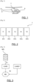
- a turboshaft engine T As an example, it is shown in [ Fig.1 ] an aircraft A (helicopter) comprising a turboshaft engine T.
- the turbo engine T comprises several modules, in particular, a low pressure compressor module 11, a high pressure compressor module 12, a combustion chamber module 13, a high pressure turbine module 14 and a low pressure turbine module 15. It goes without saying that the number and nature of the modules 11-15 could be different depending on the turbo engine concerned T.
- Each module 11-15 has its own efficiency R11-R15.
- the efficiency R11-R15 of a module 11-15 corresponds to the ratio between its actual performance and its theoretical performance of 100%.
- a variation in the efficiency R11-R15 is a sign of a defect in said module 11-15.
- a variation in efficiency corresponds to a variation in flow rate. Also, when the performance of a turbine engine T drops, it is important to determine to which module or modules 11-15 this drop in performance can be attributed.
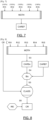
- a step E1 of determining a performance map of the turbine engine T hereinafter referred to as the “estimated actual map” CARE
- the estimated actual map CARE is obtained by computer learning from the parameter measurements MiPj acquired during a given flight of the aircraft A.
- the estimated actual map CARE makes it possible to relate a parameter Pj of the turbine engine T to at least one other parameter Pk of the turbine engine T, the parameters Pj, Pk being linked by a model determined by computer learning.
- measurements of parameters MiPj of the turbine engine T are carried out continuously or periodically.
- the measurements are carried out from sensors positioned in and in the vicinity of the turbine engine T.
- the sensors are few in number and it is not necessary to add additional sensors compared to a traditional turbine engine.
- the MiPj measurements may include in particular temperature measurements, pressure measurements, speed measurements, torque measurements or the like.
- measurements of the parameters of the environment of the turboshaft engine T are also carried out, in particular, of the external temperature and the external pressure.
- measurements are obtained for three parameters P1, P2, P3.
- the MiPj measurements are corrected during a correction sub-step ET11 in order to bring them back to comparable ambient conditions (ground ISA reference conditions).
- the MiPj measurements are converted into corrected MiPj' measurements in order to take into account the outside temperature.
- the corrected MiPj' measurements are then filtered during a filtering sub-step ET12 by comparison with certain minimum or maximum measurements or with operating conditions (in-flight measurements).
- the correction sub-step ET11 and the filtering sub-step ET12 are optional sub-steps which make it possible to highlight the relevance of the measurements for establishing the estimated real CARE maps.
- the set of measurements MiPj, MiPj', MiPj we learn, during a learning sub-step ET13, at least one mathematical relationship Fg between the different parameters Pj, Pk.
- the relationships Fg between the parameters Pj, Pk of the turbine engine T are learned by computer learning from temporally correlated measurements MiPj, MiPj', MiPj".
- the mathematical relationship Fg is learned by computer learning from several models in order to determine the most relevant mathematical relationship for said parameters Pj, Pk.
- the best mathematical relationship is obtained from the regression or classification scores.
- only part of the flight measurements is used to determine the mathematical relationship Fg linking the parameters Pj, Pk and another part of the flight measurements is used to validate the mathematical relationship Fg.
- mathematical relationship Fg between parameters Pj, Pk we mean for example an internal temperature as a function of a rotation speed, a torque as a function of a temperature, or any other thermodynamic relationship. The redundancy of these relationships allows a robust exploitation of the results.
- mathematical relationships F12, F13, F23 are represented between the parameters P1, P2 and P3.
- the learned mathematical relationships Fg make it possible to form an estimated real mapping CARE of the turboshaft engine T for the given flight VOL of the aircraft A.
- This estimated real mapping CARE makes it possible to describe the behavior of the turboshaft engine T during the given flight VOL.
- the turboshaft engine T is mathematically modeled from the measurements obtained by existing sensors.
- the mathematical relations Fg of the real CARE mapping can be determined statistically. For example, we condition the MiPj measurements in an analogous manner, determine their distribution and select the principal mode of this distribution (which corresponds to the desired mathematical relation).
- measurements of an outlet temperature parameter of the high-pressure turbine T45 and of a rotation speed parameter of the gas generator N1 are carried out continuously during operation of the turboshaft engine T.
- the environmental parameters are also measured during operation of the turboshaft engine T, in particular, the outside temperature T0 and/or the outside pressure.
- the corrected measurements T45', N1' are then filtered to keep only the most relevant corrected measurements, hereinafter, filtered measurements T45", N1".
- the corrected measurements T45', N1' are compared to predetermined thresholds (maximum and/or minimum thresholds) in order to ensure that the corrected measurements T45', N1' correspond to states where the power demand of the turbine engine is sufficiently high. In other words, the marginal measurements are removed in favor of the most relevant measurements.
- the relationship between the filtered measurements T45", N1" is then learned by computer learning. Several mathematical relationships are learned Fg to form the estimated real mapping CARE.
- the estimated actual mapping CARE is the estimated actual image of the turbine engine T during said flight of the aircraft over the operating range of the turbine engine T from a plurality of measurements MiPj obtained at different times.
- the estimated actual mapping CARE of the turbine engine T is updated.
- the method then comprises a step E2 of determining real indicators IRE from the estimated real mapping CARE and a reference mapping CAREF.
- the real indicators IRE are intended to highlight a change in the efficiencies of the modules of the turboshaft engine T by comparison between an estimated real map CARE and a reference map CAREF.
- a real indicator IRE can for example be presented as a maximum of differences between the mathematical relationships Fg of two maps CARE, CAREF, generic statistics of these differences, barycenters of the slopes of curves, etc.
- the real indicators IRE can be of different natures and are determined to translate a singularity characteristic of a drop in efficiency.
- certain real indicators IRE are configured to highlight a defect of a compressor module 11, 12 or of a turbine module 14, 15.
- the real indicators IRE correspond to a set of singularities defined mathematically.
- the CAREF reference map can be obtained in various ways.
- the CAREF reference map can be an average map of a T-engine, a map constructed from a previous flight or a simulated map.
- the CAREF reference map is obtained from a theoretical model MOTH of the turboshaft engine T, i.e. defined from a plurality of mathematical and/or thermodynamic equations.
- a theoretical model MOTH is known to those skilled in the art.
- the CAREF reference map is not based on physical measurements carried out on a turboshaft engine real T.
- the CAREF reference map is based on a theoretical MOTH model of the turboshaft engine whose R11-R15 efficiencies of modules 11-15 are perfect (100%).
- the CAREF reference map is obtained by theoretical simulation by varying the inputs of the theoretical MOTH model to obtain different outputs. In a manner similar to previously, mathematical relationships can be obtained between the inputs/outputs of the parameters Pj, Pk and a CAREF reference map can be deduced from them.
- the estimated actual CARE mapping and the CAREF reference mapping have the same mathematical relationships Fg which can thus be easily compared to form actual IRE indicators highlighting local performance defects.
- the method comprises a step E3 of estimating a change in efficiency from a mathematical model CLASS applied to the real indicators IRE. Thanks to the estimation step E3, it is possible to determine the change in the efficiency R11-R15 of each module 11-15 of the turboshaft engine T and thus determine which of the modules 11-15 is defective.
- the relevance of the CLASS mathematical model is important in order to obtain an accurate and relevant estimate of the R11-R15 performance of each 11-15 module.
- a plurality of CARSx simulated performance maps are first determined as illustrated in [ Fig.8 ].
- Each simulated CARSx map is obtained from the theoretical model MOTH of the turboshaft engine T, that is to say, defined from a plurality of mathematical and/or thermodynamic equations for which the theoretical model MOTH is parameterized with different efficiency configurations CR.
- a first efficiency configuration CR1 may indicate that the low-pressure compressor module 11 has an efficiency of 50% while the other modules 12-15 have an efficiency of 100%.
- another efficiency configuration CR2 may indicate that all the modules 11-15 have an efficiency of 80%.
- the simulated CARSx maps cover a very large number of efficiency configurations CR.
- the simulated CARSx maps are thus the image of all the degrees of degradation of the efficiency of the different modules 11-15 of the turboshaft engine T.
- the method then comprises a step E4 of determining simulated indicators ISx from the simulated CARSx maps and a reference map CAREF.
- the simulated indicators ISx are obtained in a manner analogous to the real indicators IRE, each simulated map CARSx being used in place of the estimated real map CARE.
- the simulated indicators ISx are thus elementary representatives of each CR yield configuration of the theoretical model MTH of the T turboshaft engine.
- the same CAREF reference mapping is preferably used but it goes without saying that it could be different.
- the mathematical model CLASS is learned by relating the simulated indicators ISx to CR efficiency configurations.
- the mathematical model CLASS makes it possible to assign to each simulated indicator ISx a CR efficiency configuration and, consequently, a loss of efficiency for each module 11-15 (classification), or a loss of efficiency value (regression), or deviations from reference efficiencies (regression). It is thus possible to determine the sign of the change in efficiency (loss or gain) and, preferably, the value of said change.
- analyzing the simulated indicators ISx it is thus possible to determine the individual change in the efficiency of each module 11-15 of the turboshaft engine T.
- Each CR efficiency configuration corresponds in this example to a percentage efficiency but it goes without saying that it could correspond to a change (positive or negative) or to a deviation in efficiency relative to a reference efficiency (perfect or previous).
- the CLASS mathematical model is preferably obtained by a regression operator, by a classification operator, by random forest, support vectors, nearest neighbors, etc.
- the CLASS mathematical model can be obtained by means of high-performance calculations in order to obtain a wide variety of CR efficiency configurations, i.e., precision in the nature of the defect.
- the same CLASS mathematical model can be used advantageously for many flights for turbine engines of the same type.
- the method comprises a step E6 of applying said mathematical model CLASS to the real indicators IRE so as to deduce therefrom a real yield configuration.
- the use of the mathematical model CLASS requires modest computing power, which makes it possible to determine a yield defect reactively after each given flight VOL.
- the method comprises a step of monitoring the yields R11-R15 of each module 11-15 and determining a defect if at least one of the yields is lower than a threshold or if its slope is lower than a threshold.
- the evolution of the yields is monitored individually and/or globally.
Landscapes
- Engineering & Computer Science (AREA)
- Chemical & Material Sciences (AREA)
- Combustion & Propulsion (AREA)
- Physics & Mathematics (AREA)
- General Engineering & Computer Science (AREA)
- Mechanical Engineering (AREA)
- Mathematical Physics (AREA)
- Automation & Control Theory (AREA)
- General Physics & Mathematics (AREA)
- Evolutionary Computation (AREA)
- Artificial Intelligence (AREA)
- Manufacturing & Machinery (AREA)
- Transportation (AREA)
- Aviation & Aerospace Engineering (AREA)
- Testing Of Devices, Machine Parts, Or Other Structures Thereof (AREA)
- Feedback Control In General (AREA)
- Control Of Turbines (AREA)
Claims (9)
- Verfahren zur Bestimmung eines Wirkungsgradfehlers (R11-R15) von mindestens einem Modul (11-15) eines Turbomotors (T) eines Luftfahrzeugs (A), wobei der Turbomotor (T) mindestens ein Kompressormodul (11, 12), mindestens ein Brennkammermodul (13) und mindestens ein Turbinenmodul (14, 15) umfasst, wobei jedes Modul einen ihm eigenen Wirkungsgrad (R11-R15) aufweist, wobei das Bestimmungsverfahren umfasst:• einen Schritt des Bestimmens (E1) einer Leistungskartographie des Turbomotors (T), nachfolgend "geschätzte reale Kartographie" (CARE), wobei die geschätzte reale Kartographie (CARE) eine Vielzahl mathematischer Beziehungen (Fg) zwischen Parametern (Pj) des Turbomotors (T) definiert, wobei jede mathematische Beziehung (Fg) anhand von Messungen von Parametern (Pj) des Turbomotors (T) bestimmt wird, die während eines gegebenen Fluges (VOL) des Flugzeugs (A) erfasst werden,• einen Schritt des Bestimmens (E2) realer Indikatoren (IRE) anhand der realen Kartographie (CARE), wobei die realen Indikatoren (IRE) Betriebssingularitäten des vorbestimmten Turbomotors (T) entsprechen,• einen Schritt des Bestimmens (E3) einer Vielzahl von Leistungskartographien anhand einer Simulation eines theoretischen Modells (MOTH) des Turbomotors (T) für verschiedene Wirkungsgradkonfigurationen (CR), nachfolgend "simulierte Kartographien" (CARSx), wobei die Wirkungsgradkonfiguration (CR) den Wirkungsgrad (R11-R15) jedes Moduls (11-15) bestimmt,• einen Schritt des Bestimmens (E4) simulierter Indikatoren (ISx) für jede simulierte Kartographie (CARSx), wobei die simulierten Indikatoren (ISx) Betriebssingularitäten der vorbestimmten Turbomotor (T) entsprechen,• einen Schritt des Anlernens (E5) eines mathematischen Modells (CLASS) durch In-Beziehung-Setzen der simulierten Indikatoren (ISx) zu Wirkungsgradkonfigurationen (CR) und• einen Schritt des Anwendens (E6) des mathematischen Modells (CLASS) auf die realen Indikatoren (IRE), um daraus eine reale Wirkungsgradkonfiguration (CR) abzuleiten.
- Verfahren nach Anspruch 1, wobei während des Bestimmungsschritts (E2) die realen Indikatoren (IRE) durch Vergleich der realen Kartographie (CARE) mit einer Referenzkartographie (CAREF1) bestimmt werden.
- Verfahren nach Anspruch 2, wobei die Referenzkartographie (CAREF) anhand der Simulation eines theoretischen Modells (MOTH) des Turbomotors (T) erhalten wird, wofür der Wirkungsgrad (R11-R15) jedes Moduls (11-15) perfekt ist.
- Verfahren nach einem der Ansprüche 1 bis 3, wobei ein Korrekturunterschritt (ET11) und ein Filterunterschritt (ET12) an den Parametermessungen (Pj) des Turbomotors (T) während des Bestimmungsschritts (E1) der realen Kartographie (CARE) durchgeführt werden.
- Verfahren nach einem der Ansprüche 1 bis 4, wobei jede mathematische Beziehung (Fg) durch rechnergesteuertes Lernen anhand der Parametermessungen (Pj) des Turbomotors (T) erhalten wird, die während eines gegebenen Fluges (VOL) des Luftfahrzeugs (A) erfasst werden.
- Verfahren nach Anspruch 5, wobei jede mathematische Beziehung (Fg) durch rechnergesteuertes Lernen anhand mehrerer Modelle erhalten wird, um die relevanteste mathematische Beziehung für die Parameter (Pj) zu bestimmen, wobei die beste mathematische Beziehung (Fg) anhand der Regressions- oder Klassifizierungsergebnisse gewonnen wird.
- Verfahren nach einem der Ansprüche 5 bis 6, wobei jede mathematische Beziehung (Fg) durch rechnergesteuertes Lernen anhand eines Teils der Parametermessungen (Pj) des Turbomotors (T) erhalten wird, die während eines gegebenen Fluges des Luftfahrzeugs (A) erfasst wurden, wobei ein anderer Teil der Parametermessungen (Pj) verwendet wird, um die erhaltene mathematische Beziehung (Fg) zu validieren.
- Rechnerprogramm, das Anweisungen zur Ausführung der Schritte des Verfahrens zur Bestimmung eines Wirkungsgradfehlers nach einem der Ansprüche 1 bis 7 umfasst, wenn das Programm von einem Rechner ausgeführt wird.
- IT-Medium, das das Rechnerprogramm nach Anspruch 8 umfasst.
Applications Claiming Priority (2)
| Application Number | Priority Date | Filing Date | Title |
|---|---|---|---|
| FR2011242A FR3115824B1 (fr) | 2020-11-03 | 2020-11-03 | Procédé de détermination de défaut d’un rendement d’un module d’un turbomoteur d’un aéronef |
| PCT/EP2021/079926 WO2022096354A1 (fr) | 2020-11-03 | 2021-10-28 | Procédé de détermination de défaut d'un rendement d'un module d'un turbomoteur d'un aéronef |
Publications (2)
| Publication Number | Publication Date |
|---|---|
| EP4240952A1 EP4240952A1 (de) | 2023-09-13 |
| EP4240952B1 true EP4240952B1 (de) | 2024-11-27 |
Family
ID=74045841
Family Applications (1)
| Application Number | Title | Priority Date | Filing Date |
|---|---|---|---|
| EP21801531.1A Active EP4240952B1 (de) | 2020-11-03 | 2021-10-28 | Verfahren zur bestimmung eines effizienzfehlers eines flugzeugturbowellenmotormoduls |
Country Status (6)
| Country | Link |
|---|---|
| US (1) | US12552551B2 (de) |
| EP (1) | EP4240952B1 (de) |
| CN (1) | CN116368442A (de) |
| CA (1) | CA3196672A1 (de) |
| FR (1) | FR3115824B1 (de) |
| WO (1) | WO2022096354A1 (de) |
Families Citing this family (1)
| Publication number | Priority date | Publication date | Assignee | Title |
|---|---|---|---|---|
| FR3167619A1 (fr) * | 2024-10-21 | 2026-04-24 | Safran Helicopter Engines | Procede et systeme de controle des performances de moteurs d’helicoptere a haute frequence et faible variabilite |
Citations (1)
| Publication number | Priority date | Publication date | Assignee | Title |
|---|---|---|---|---|
| EP2699778B1 (de) * | 2011-04-21 | 2015-04-22 | Renault S.A.S. | Verfahren zur fehlerdiagnose eines aufgeladenen motors und aufgeladener motor |
Family Cites Families (12)
| Publication number | Priority date | Publication date | Assignee | Title |
|---|---|---|---|---|
| FR2790793B1 (fr) * | 1999-03-12 | 2001-04-27 | Siemens Automotive Sa | Procede de determination d'un parametre de fonctionnement d'un moteur a combustion interne en fonction de trois parametres de commande de ce moteur |
| DE10020448B4 (de) * | 2000-04-26 | 2005-05-04 | Daimlerchrysler Ag | Verfahren und Vorrichtung zur Optimierung des Betriebs eines Verbrennungsmotors |
| US7302334B2 (en) * | 2002-08-02 | 2007-11-27 | General Electric Company | Automatic mapping logic for a combustor in a gas turbine engine |
| DE102004026583B3 (de) * | 2004-05-28 | 2005-11-24 | Robert Bosch Gmbh | Verfahren zur Optimierung von Kennfeldern |
| US7788014B2 (en) * | 2007-03-05 | 2010-08-31 | United Technologies Corporation | Process and methodology for root cause identification in gas turbine engine performance tracking |
| US20100257838A1 (en) * | 2009-04-09 | 2010-10-14 | General Electric Company | Model based health monitoring of aeroderivatives, robust to sensor failure and profiling |
| EP2905666A1 (de) * | 2014-02-07 | 2015-08-12 | Siemens Aktiengesellschaft | Schätzung von Gesundheitsparametern in industriellen Gasturbinen |
| US10466661B2 (en) * | 2015-12-18 | 2019-11-05 | General Electric Company | Model-based performance estimation |
| US20170286572A1 (en) * | 2016-03-31 | 2017-10-05 | General Electric Company | Digital twin of twinned physical system |
| US10247032B2 (en) * | 2017-03-28 | 2019-04-02 | Honeywell International Inc. | Gas turbine engine and test cell real-time diagnostic fault detection and corrective action system and method |
| US10508597B2 (en) * | 2017-04-12 | 2019-12-17 | General Electric Company | Systems and methods for icing detection of compressors |
| US11334854B2 (en) * | 2017-11-10 | 2022-05-17 | General Electric Company | Systems and methods to generate an asset workscope |
-
2020
- 2020-11-03 FR FR2011242A patent/FR3115824B1/fr active Active
-
2021
- 2021-10-28 EP EP21801531.1A patent/EP4240952B1/de active Active
- 2021-10-28 CN CN202180074642.4A patent/CN116368442A/zh active Pending
- 2021-10-28 US US18/251,340 patent/US12552551B2/en active Active
- 2021-10-28 CA CA3196672A patent/CA3196672A1/fr active Pending
- 2021-10-28 WO PCT/EP2021/079926 patent/WO2022096354A1/fr not_active Ceased
Patent Citations (1)
| Publication number | Priority date | Publication date | Assignee | Title |
|---|---|---|---|---|
| EP2699778B1 (de) * | 2011-04-21 | 2015-04-22 | Renault S.A.S. | Verfahren zur fehlerdiagnose eines aufgeladenen motors und aufgeladener motor |
Also Published As
| Publication number | Publication date |
|---|---|
| FR3115824A1 (fr) | 2022-05-06 |
| WO2022096354A1 (fr) | 2022-05-12 |
| EP4240952A1 (de) | 2023-09-13 |
| FR3115824B1 (fr) | 2022-09-30 |
| US20230415921A1 (en) | 2023-12-28 |
| US12552551B2 (en) | 2026-02-17 |
| CN116368442A (zh) | 2023-06-30 |
| CA3196672A1 (fr) | 2022-05-12 |
Similar Documents
| Publication | Publication Date | Title |
|---|---|---|
| CA2746537C (fr) | Standardisation de donnees utilisees pour la surveillance d'un moteur d'aeronef | |
| EP2376989B1 (de) | Identifikation von defekten in einem flugzeugtriebwerk | |
| EP2368161B1 (de) | Detektion von anomalien in einem flugzeugtriebwerk | |
| EP3039497B1 (de) | Überwachung eines flugzeugmotors zur vorausplanung von wartungsoperationen | |
| EP3008531B1 (de) | Verfahren zur erstellung einer datenbank und zur formulierung einer karte von betriebszuständen eines flugzeugs sowie verfahren zur überwachung des betriebs eines entsprechenden flugzeugs | |
| FR2793845A1 (fr) | Procede et dispositif d'evaluation de la sante d'un moteur | |
| FR3046268A1 (fr) | Systeme d'exploitation de donnees de vol d'un aeronef | |
| EP2912526A2 (de) | System zur überwachung einer gruppe von komponenten einer vorrichtung | |
| WO2016075409A1 (fr) | Procédé de surveillance d'un moteur d'aéronef en fonctionnement dans un environnement donné | |
| EP3941826A1 (de) | System und verfahren zur überwachung eines flugzeugmotors | |
| FR2971870A1 (fr) | Methode de detection de pannes d'une turbomachine au moyen d'un modele theorique du cycle thermodynamique de ladite turbomachine | |
| FR3035232A1 (fr) | Systeme de surveillance de l'etat de sante d'un moteur et procede de configuration associe | |
| EP4240952B1 (de) | Verfahren zur bestimmung eines effizienzfehlers eines flugzeugturbowellenmotormoduls | |
| FR3009021A1 (fr) | Procede d'estimation sur une courbe d'un point pertinent pour la detection d'anomalie d'un moteur et systeme de traitement de donnees pour sa mise en oeuvre | |
| EP3066445B1 (de) | Technisches testverfahren | |
| EP4499988A1 (de) | Verfahren zur überwachung des gesundheitszustands einer flugzeugturbomaschine | |
| FR3096031A1 (fr) | Recalage de modèle par segment ou plan dans une turbomachine | |
| FR3150290A1 (fr) | Procédé et dispositif de suivi d’un état d’un moteur d’un aéronef et programme d’ordinateur associé | |
| EP4417939A1 (de) | Verfahren zur bereitstellung eines flugplans für ein flugzeug | |
| FR3133884A1 (fr) | Procédé de surveillance de l’état de santé de turbomachine d’aéronef | |
| FR3158120A1 (fr) | Procede et systeme de surveillance de la performance d’une turbine haute pression d’un moteur d’un aeronef | |
| FR3134451A1 (fr) | Détection et correction de biais de mesure dans des données mesurées au moyen d’équipements d’essais interchangeables de même type | |
| EP3969967A1 (de) | Modellrücksetzung in einem turbinentriebwerk | |
| FR3132766A1 (fr) | Estimation d’une amplitude de flottement d’une soufflante d’une turbomachine |
Legal Events
| Date | Code | Title | Description |
|---|---|---|---|
| STAA | Information on the status of an ep patent application or granted ep patent |
Free format text: STATUS: UNKNOWN |
|
| STAA | Information on the status of an ep patent application or granted ep patent |
Free format text: STATUS: THE INTERNATIONAL PUBLICATION HAS BEEN MADE |
|
| PUAI | Public reference made under article 153(3) epc to a published international application that has entered the european phase |
Free format text: ORIGINAL CODE: 0009012 |
|
| STAA | Information on the status of an ep patent application or granted ep patent |
Free format text: STATUS: REQUEST FOR EXAMINATION WAS MADE |
|
| 17P | Request for examination filed |
Effective date: 20230425 |
|
| AK | Designated contracting states |
Kind code of ref document: A1 Designated state(s): AL AT BE BG CH CY CZ DE DK EE ES FI FR GB GR HR HU IE IS IT LI LT LU LV MC MK MT NL NO PL PT RO RS SE SI SK SM TR |
|
| DAV | Request for validation of the european patent (deleted) | ||
| DAX | Request for extension of the european patent (deleted) | ||
| GRAP | Despatch of communication of intention to grant a patent |
Free format text: ORIGINAL CODE: EPIDOSNIGR1 |
|
| STAA | Information on the status of an ep patent application or granted ep patent |
Free format text: STATUS: GRANT OF PATENT IS INTENDED |
|
| INTG | Intention to grant announced |
Effective date: 20240607 |
|
| GRAS | Grant fee paid |
Free format text: ORIGINAL CODE: EPIDOSNIGR3 |
|
| GRAA | (expected) grant |
Free format text: ORIGINAL CODE: 0009210 |
|
| STAA | Information on the status of an ep patent application or granted ep patent |
Free format text: STATUS: THE PATENT HAS BEEN GRANTED |
|
| AK | Designated contracting states |
Kind code of ref document: B1 Designated state(s): AL AT BE BG CH CY CZ DE DK EE ES FI FR GB GR HR HU IE IS IT LI LT LU LV MC MK MT NL NO PL PT RO RS SE SI SK SM TR |
|
| REG | Reference to a national code |
Ref country code: GB Ref legal event code: FG4D Free format text: NOT ENGLISH |
|
| REG | Reference to a national code |
Ref country code: CH Ref legal event code: EP |
|
| REG | Reference to a national code |
Ref country code: IE Ref legal event code: FG4D Free format text: LANGUAGE OF EP DOCUMENT: FRENCH |
|
| REG | Reference to a national code |
Ref country code: DE Ref legal event code: R096 Ref document number: 602021022538 Country of ref document: DE |
|
| REG | Reference to a national code |
Ref country code: LT Ref legal event code: MG9D |
|
| REG | Reference to a national code |
Ref country code: NL Ref legal event code: MP Effective date: 20241127 |
|
| PG25 | Lapsed in a contracting state [announced via postgrant information from national office to epo] |
Ref country code: HR Free format text: LAPSE BECAUSE OF FAILURE TO SUBMIT A TRANSLATION OF THE DESCRIPTION OR TO PAY THE FEE WITHIN THE PRESCRIBED TIME-LIMIT Effective date: 20241127 Ref country code: IS Free format text: LAPSE BECAUSE OF FAILURE TO SUBMIT A TRANSLATION OF THE DESCRIPTION OR TO PAY THE FEE WITHIN THE PRESCRIBED TIME-LIMIT Effective date: 20250327 Ref country code: PT Free format text: LAPSE BECAUSE OF FAILURE TO SUBMIT A TRANSLATION OF THE DESCRIPTION OR TO PAY THE FEE WITHIN THE PRESCRIBED TIME-LIMIT Effective date: 20250327 |
|
| PG25 | Lapsed in a contracting state [announced via postgrant information from national office to epo] |
Ref country code: FI Free format text: LAPSE BECAUSE OF FAILURE TO SUBMIT A TRANSLATION OF THE DESCRIPTION OR TO PAY THE FEE WITHIN THE PRESCRIBED TIME-LIMIT Effective date: 20241127 Ref country code: NL Free format text: LAPSE BECAUSE OF FAILURE TO SUBMIT A TRANSLATION OF THE DESCRIPTION OR TO PAY THE FEE WITHIN THE PRESCRIBED TIME-LIMIT Effective date: 20241127 |
|
| REG | Reference to a national code |
Ref country code: AT Ref legal event code: MK05 Ref document number: 1745915 Country of ref document: AT Kind code of ref document: T Effective date: 20241127 |
|
| PG25 | Lapsed in a contracting state [announced via postgrant information from national office to epo] |
Ref country code: BG Free format text: LAPSE BECAUSE OF FAILURE TO SUBMIT A TRANSLATION OF THE DESCRIPTION OR TO PAY THE FEE WITHIN THE PRESCRIBED TIME-LIMIT Effective date: 20241127 |
|
| PG25 | Lapsed in a contracting state [announced via postgrant information from national office to epo] |
Ref country code: ES Free format text: LAPSE BECAUSE OF FAILURE TO SUBMIT A TRANSLATION OF THE DESCRIPTION OR TO PAY THE FEE WITHIN THE PRESCRIBED TIME-LIMIT Effective date: 20241127 |
|
| PG25 | Lapsed in a contracting state [announced via postgrant information from national office to epo] |
Ref country code: NO Free format text: LAPSE BECAUSE OF FAILURE TO SUBMIT A TRANSLATION OF THE DESCRIPTION OR TO PAY THE FEE WITHIN THE PRESCRIBED TIME-LIMIT Effective date: 20250227 |
|
| PG25 | Lapsed in a contracting state [announced via postgrant information from national office to epo] |
Ref country code: LV Free format text: LAPSE BECAUSE OF FAILURE TO SUBMIT A TRANSLATION OF THE DESCRIPTION OR TO PAY THE FEE WITHIN THE PRESCRIBED TIME-LIMIT Effective date: 20241127 Ref country code: AT Free format text: LAPSE BECAUSE OF FAILURE TO SUBMIT A TRANSLATION OF THE DESCRIPTION OR TO PAY THE FEE WITHIN THE PRESCRIBED TIME-LIMIT Effective date: 20241127 Ref country code: GR Free format text: LAPSE BECAUSE OF FAILURE TO SUBMIT A TRANSLATION OF THE DESCRIPTION OR TO PAY THE FEE WITHIN THE PRESCRIBED TIME-LIMIT Effective date: 20250228 |
|
| PG25 | Lapsed in a contracting state [announced via postgrant information from national office to epo] |
Ref country code: PL Free format text: LAPSE BECAUSE OF FAILURE TO SUBMIT A TRANSLATION OF THE DESCRIPTION OR TO PAY THE FEE WITHIN THE PRESCRIBED TIME-LIMIT Effective date: 20241127 |
|
| PG25 | Lapsed in a contracting state [announced via postgrant information from national office to epo] |
Ref country code: RS Free format text: LAPSE BECAUSE OF FAILURE TO SUBMIT A TRANSLATION OF THE DESCRIPTION OR TO PAY THE FEE WITHIN THE PRESCRIBED TIME-LIMIT Effective date: 20250227 |
|
| PG25 | Lapsed in a contracting state [announced via postgrant information from national office to epo] |
Ref country code: SM Free format text: LAPSE BECAUSE OF FAILURE TO SUBMIT A TRANSLATION OF THE DESCRIPTION OR TO PAY THE FEE WITHIN THE PRESCRIBED TIME-LIMIT Effective date: 20241127 |
|
| PG25 | Lapsed in a contracting state [announced via postgrant information from national office to epo] |
Ref country code: DK Free format text: LAPSE BECAUSE OF FAILURE TO SUBMIT A TRANSLATION OF THE DESCRIPTION OR TO PAY THE FEE WITHIN THE PRESCRIBED TIME-LIMIT Effective date: 20241127 |
|
| PG25 | Lapsed in a contracting state [announced via postgrant information from national office to epo] |
Ref country code: EE Free format text: LAPSE BECAUSE OF FAILURE TO SUBMIT A TRANSLATION OF THE DESCRIPTION OR TO PAY THE FEE WITHIN THE PRESCRIBED TIME-LIMIT Effective date: 20241127 |
|
| PG25 | Lapsed in a contracting state [announced via postgrant information from national office to epo] |
Ref country code: RO Free format text: LAPSE BECAUSE OF FAILURE TO SUBMIT A TRANSLATION OF THE DESCRIPTION OR TO PAY THE FEE WITHIN THE PRESCRIBED TIME-LIMIT Effective date: 20241127 |
|
| PG25 | Lapsed in a contracting state [announced via postgrant information from national office to epo] |
Ref country code: SK Free format text: LAPSE BECAUSE OF FAILURE TO SUBMIT A TRANSLATION OF THE DESCRIPTION OR TO PAY THE FEE WITHIN THE PRESCRIBED TIME-LIMIT Effective date: 20241127 |
|
| PG25 | Lapsed in a contracting state [announced via postgrant information from national office to epo] |
Ref country code: CZ Free format text: LAPSE BECAUSE OF FAILURE TO SUBMIT A TRANSLATION OF THE DESCRIPTION OR TO PAY THE FEE WITHIN THE PRESCRIBED TIME-LIMIT Effective date: 20241127 |
|
| PG25 | Lapsed in a contracting state [announced via postgrant information from national office to epo] |
Ref country code: IT Free format text: LAPSE BECAUSE OF FAILURE TO SUBMIT A TRANSLATION OF THE DESCRIPTION OR TO PAY THE FEE WITHIN THE PRESCRIBED TIME-LIMIT Effective date: 20241127 |
|
| REG | Reference to a national code |
Ref country code: DE Ref legal event code: R097 Ref document number: 602021022538 Country of ref document: DE |
|
| PG25 | Lapsed in a contracting state [announced via postgrant information from national office to epo] |
Ref country code: SE Free format text: LAPSE BECAUSE OF FAILURE TO SUBMIT A TRANSLATION OF THE DESCRIPTION OR TO PAY THE FEE WITHIN THE PRESCRIBED TIME-LIMIT Effective date: 20241127 |
|
| PLBE | No opposition filed within time limit |
Free format text: ORIGINAL CODE: 0009261 |
|
| STAA | Information on the status of an ep patent application or granted ep patent |
Free format text: STATUS: NO OPPOSITION FILED WITHIN TIME LIMIT |
|
| 26N | No opposition filed |
Effective date: 20250828 |
|
| PGFP | Annual fee paid to national office [announced via postgrant information from national office to epo] |
Ref country code: DE Payment date: 20251020 Year of fee payment: 5 |
|
| PGFP | Annual fee paid to national office [announced via postgrant information from national office to epo] |
Ref country code: GB Payment date: 20251029 Year of fee payment: 5 |
|
| PGFP | Annual fee paid to national office [announced via postgrant information from national office to epo] |
Ref country code: FR Payment date: 20251024 Year of fee payment: 5 |