EP4240677B1 - Supporting structure for controlled gravity displacement of carried material and a device having the same - Google Patents
Supporting structure for controlled gravity displacement of carried material and a device having the same Download PDFInfo
- Publication number
- EP4240677B1 EP4240677B1 EP21835153.4A EP21835153A EP4240677B1 EP 4240677 B1 EP4240677 B1 EP 4240677B1 EP 21835153 A EP21835153 A EP 21835153A EP 4240677 B1 EP4240677 B1 EP 4240677B1
- Authority
- EP
- European Patent Office
- Prior art keywords
- supporting structure
- envelope
- spiral
- supporting
- spiral support
- Prior art date
- Legal status (The legal status is an assumption and is not a legal conclusion. Google has not performed a legal analysis and makes no representation as to the accuracy of the status listed.)
- Active
Links
Images




Classifications
-
- B—PERFORMING OPERATIONS; TRANSPORTING
- B65—CONVEYING; PACKING; STORING; HANDLING THIN OR FILAMENTARY MATERIAL
- B65G—TRANSPORT OR STORAGE DEVICES, e.g. CONVEYORS FOR LOADING OR TIPPING, SHOP CONVEYOR SYSTEMS OR PNEUMATIC TUBE CONVEYORS
- B65G33/00—Screw or rotary spiral conveyors
- B65G33/02—Screw or rotary spiral conveyors for articles
-
- B—PERFORMING OPERATIONS; TRANSPORTING
- B65—CONVEYING; PACKING; STORING; HANDLING THIN OR FILAMENTARY MATERIAL
- B65G—TRANSPORT OR STORAGE DEVICES, e.g. CONVEYORS FOR LOADING OR TIPPING, SHOP CONVEYOR SYSTEMS OR PNEUMATIC TUBE CONVEYORS
- B65G33/00—Screw or rotary spiral conveyors
- B65G33/08—Screw or rotary spiral conveyors for fluent solid materials
- B65G33/14—Screw or rotary spiral conveyors for fluent solid materials comprising a screw or screws enclosed in a tubular housing
- B65G33/18—Screw or rotary spiral conveyors for fluent solid materials comprising a screw or screws enclosed in a tubular housing with multiple screws in parallel arrangements, e.g. concentric
-
- B—PERFORMING OPERATIONS; TRANSPORTING
- B65—CONVEYING; PACKING; STORING; HANDLING THIN OR FILAMENTARY MATERIAL
- B65G—TRANSPORT OR STORAGE DEVICES, e.g. CONVEYORS FOR LOADING OR TIPPING, SHOP CONVEYOR SYSTEMS OR PNEUMATIC TUBE CONVEYORS
- B65G33/00—Screw or rotary spiral conveyors
- B65G33/08—Screw or rotary spiral conveyors for fluent solid materials
-
- B—PERFORMING OPERATIONS; TRANSPORTING
- B65—CONVEYING; PACKING; STORING; HANDLING THIN OR FILAMENTARY MATERIAL
- B65G—TRANSPORT OR STORAGE DEVICES, e.g. CONVEYORS FOR LOADING OR TIPPING, SHOP CONVEYOR SYSTEMS OR PNEUMATIC TUBE CONVEYORS
- B65G33/00—Screw or rotary spiral conveyors
- B65G33/24—Details
- B65G33/26—Screws
- B65G33/30—Screws with a discontinuous helical surface
-
- C—CHEMISTRY; METALLURGY
- C05—FERTILISERS; MANUFACTURE THEREOF
- C05F—ORGANIC FERTILISERS NOT COVERED BY SUBCLASSES C05B, C05C, e.g. FERTILISERS FROM WASTE OR REFUSE
- C05F17/00—Preparation of fertilisers characterised by biological or biochemical treatment steps, e.g. composting or fermentation
- C05F17/20—Preparation of fertilisers characterised by biological or biochemical treatment steps, e.g. composting or fermentation using specific microorganisms or substances, e.g. enzymes, for activating or stimulating the treatment
-
- C—CHEMISTRY; METALLURGY
- C05—FERTILISERS; MANUFACTURE THEREOF
- C05F—ORGANIC FERTILISERS NOT COVERED BY SUBCLASSES C05B, C05C, e.g. FERTILISERS FROM WASTE OR REFUSE
- C05F17/00—Preparation of fertilisers characterised by biological or biochemical treatment steps, e.g. composting or fermentation
- C05F17/60—Heating or cooling during the treatment
-
- C—CHEMISTRY; METALLURGY
- C05—FERTILISERS; MANUFACTURE THEREOF
- C05F—ORGANIC FERTILISERS NOT COVERED BY SUBCLASSES C05B, C05C, e.g. FERTILISERS FROM WASTE OR REFUSE
- C05F17/00—Preparation of fertilisers characterised by biological or biochemical treatment steps, e.g. composting or fermentation
- C05F17/90—Apparatus therefor
- C05F17/95—Devices in which the material is conveyed essentially vertically between inlet and discharge means
-
- C—CHEMISTRY; METALLURGY
- C05—FERTILISERS; MANUFACTURE THEREOF
- C05F—ORGANIC FERTILISERS NOT COVERED BY SUBCLASSES C05B, C05C, e.g. FERTILISERS FROM WASTE OR REFUSE
- C05F17/00—Preparation of fertilisers characterised by biological or biochemical treatment steps, e.g. composting or fermentation
- C05F17/90—Apparatus therefor
- C05F17/964—Constructional parts, e.g. floors, covers or doors
- C05F17/971—Constructional parts, e.g. floors, covers or doors for feeding or discharging materials to be treated; for feeding or discharging other material
- C05F17/979—Constructional parts, e.g. floors, covers or doors for feeding or discharging materials to be treated; for feeding or discharging other material the other material being gaseous
-
- Y—GENERAL TAGGING OF NEW TECHNOLOGICAL DEVELOPMENTS; GENERAL TAGGING OF CROSS-SECTIONAL TECHNOLOGIES SPANNING OVER SEVERAL SECTIONS OF THE IPC; TECHNICAL SUBJECTS COVERED BY FORMER USPC CROSS-REFERENCE ART COLLECTIONS [XRACs] AND DIGESTS
- Y02—TECHNOLOGIES OR APPLICATIONS FOR MITIGATION OR ADAPTATION AGAINST CLIMATE CHANGE
- Y02P—CLIMATE CHANGE MITIGATION TECHNOLOGIES IN THE PRODUCTION OR PROCESSING OF GOODS
- Y02P20/00—Technologies relating to chemical industry
- Y02P20/141—Feedstock
- Y02P20/145—Feedstock the feedstock being materials of biological origin
-
- Y—GENERAL TAGGING OF NEW TECHNOLOGICAL DEVELOPMENTS; GENERAL TAGGING OF CROSS-SECTIONAL TECHNOLOGIES SPANNING OVER SEVERAL SECTIONS OF THE IPC; TECHNICAL SUBJECTS COVERED BY FORMER USPC CROSS-REFERENCE ART COLLECTIONS [XRACs] AND DIGESTS
- Y02—TECHNOLOGIES OR APPLICATIONS FOR MITIGATION OR ADAPTATION AGAINST CLIMATE CHANGE
- Y02W—CLIMATE CHANGE MITIGATION TECHNOLOGIES RELATED TO WASTEWATER TREATMENT OR WASTE MANAGEMENT
- Y02W30/00—Technologies for solid waste management
- Y02W30/40—Bio-organic fraction processing; Production of fertilisers from the organic fraction of waste or refuse
Definitions
- the present invention relates to a device for feeding in, agitating, aerating, and feeding out of a material, in particular the material comprising biodegradable waste (e.g., undersize fractions of communal waste) with optional drying for improving homogeneity and controlling of the aerobic processes.
- a material comprising biodegradable waste (e.g., undersize fractions of communal waste) with optional drying for improving homogeneity and controlling of the aerobic processes.
- biodegradable waste is preferably agitated, and/or loosened for their homogenization, possibly for reduction of microbiological contamination within closed aerobic fermentation reactors or on loose heaps or "shaped clamps".
- the waste may comprise only biodegradable waste (pure biomass, which is a mixture of organic materials), or communal waste, which includes biologically not degradable components in addition to the biodegradable ones. In this case, it may in particular comprise the undersize fraction of the communal waste.
- the temperature in said biodegradable material increases, wherein the loosening may eliminate the process, or provide equal distribution and optimization of the temperature across the material volume.
- the process occurs in the aerobic environment with optional feed of external heat to stabilize the aerobic fermentation process.
- a device for loosening and plumping of the fermenting bio-waste up is known from EP 358,986 , for example.
- the device is used for separation of material layers and comprises a belt circulating around vertical axes.
- a milling cutter is located on the belt surface. As the belt moves, the milling cutter splits up the front layer of loosely loaded material, and the downstream inclined belt conveyor moves the material to a new secondary storing (fermenting) area.
- the disadvantages of the device include taking up a large storage area over which the material is repeatedly moved in proportion to the volume of the material being processed. Transferring of the material using the milling cutter is energy demanding but essential for the whole system to operate.
- CZ 1377 U Another device for transferring of the material is disclosed in CZ 1377 U .
- a device comprising horizontally moving milling cutter for separating and bringing the lower layer of the material up.
- the milling cutter in the form of a shaft with blades in helical arrangement having winding opposite from each other from the centre brings material up to an opening along the longitudinal axis of the fermentation conduit.
- a horizontal conveyer located under the longitudinal opening transports the material for further processing.
- the disadvantage of the device is that the milled material is moved by the milling cutter across the conduit to the central opening, and energy loss occurs across the path by friction.
- longitudinal slots through which finer particles of the material being processed are falling out in an uncontrolled way, are needed for free travel of the milling cutter in the conduit.
- the fermentation process is influenced by ambient temperature and at the same time, the surrounding environment is subject to the burden by the gases that escape the fermentation.
- the main disadvantage is the unfavourable proportion of the processed material volume per unit of surface area.
- CZ 14978 U Another device is disclosed in CZ 14978 U .
- a closed fermentation reactor of which movable floor comprises a system of parallel and horizontally arranged milling cutters.
- Each milling cutter is arranged to an indexing shaft, wherein the rotation angle is in the range from 80° to 120°.
- the milling cutter shafts are driven by a chain with linear reciprocating and transferring motion.
- the indexing induces successive reciprocating motion of the juxtaposed milling cutters.
- Each milling cutter when indexed to the opposite end position, cuts off the lower part of the material layer.
- the released material falls through to the space under the milling cutter and may be returned back to the upper layer of the material or used for further processing.
- the disadvantage of the device is the necessity of frequent mixing by the milling cutters in case of higher layer of the material to subside. Again, the persisting disadvantage is the unfavourable proportion of the processed material volume per unit of surface area.
- CN 109,896,174 discloses a silo for agitating of contents thereof, being usable for aerobic fermentation of the material comprising the biodegradable waste.
- the silo has a cylindrical shape and includes a vertically oriented rotary shaft with an actuator.
- the shaft is provided with a plurality of agitating and aerating blades. When the shaft rotates, the stored material is agitated, loosened, and aerated. Placement of blades at multiple levels on top of each other allows processing of a higher volume of material stored in a thick layer at the same time. Thereby, more favourable proportion of volume of the material being processed per unit of surface area is achieved.
- the disadvantage is, however, high forces needed for rotation of the shaft with the blades through the volume of the material.
- a robust actuator is required based on hydraulic pistons having high electricity consumption with a massive structure of the work, fitting of the shaft and actuator thereof that can withstand forces generated in operation of the silo.
- US 4169878 A discloses a waste disposal unit comprises a non-rotatable vertical cylinder having a waste inlet at the top. From the inlet a ramp extends downwardly to the bottom of the cylinder in a helical pattern. The slope of the ramp is sufficient such that the waste moves down it solely by the action of gravity. A continuous flow of fresh oxygen-containing air is admitted to the cylinder so that the waste material is composted by the time it reaches the bottom of the cylinder. Gaseous products are discharged from the cylinder. Again, the persisting disadvantage is the unfavourable proportion of the processed material volume per unit of surface area.
- US 4169878 A discloses a supporting structure for controlled gravity displacement of carried material according to the preamble of claim 1.
- the objective of the present invention is to provide a device that enables drying of the material or aerobic fermentation of the material comprising biodegradable waste in an energysaving process and under ideal conditions and while occupying a small surface area and with a small enclosure.
- a supporting structure for controlled gravity displacement of a material in particular the material comprising biodegradable waste (e.g., undersize fractions of the communal waste), allowing controlled aeration.
- the supporting structure allows desirable penetration of gases through the carried material.
- Such a supporting structure is defined in claim 1.
- the material is processed during the gravity displacement.
- the processing refers to, in particular, aerobic fermentation or drying.
- the gas penetrating through the material is air.
- the gas may be exhaust gases of elevated temperature.
- specific gases of various properties and temperatures may be used. The specific influence refers to disinfection, dyeing, bacterial inoculation and more, for example.
- the supporting structure includes at least two spiral supports having an upper surface and a lower surface.
- the upper surface and lower surface refer to an area of the material of the spiral supports in case these are the spiral supports comprising the planar supporting elements.
- the upper surface and lower surface are for the purpose of the present application defined as an imaginary slid area, shape of which follows (touches) the upper and lower sides of the supporting elements.
- the spiral supports form coils. It means that points of the spiral support having mutually different angular positions have mutually different vertical position at the same time.
- the spiral support is coiled in the space according to interposed definition spiral with a pitch.
- the spiral support is defined by its pitch or number of spiral revolutions and height of the spiral. All the spiral supports have identical axis.
- origins of the spiral supports may be slightly rotated relatively from each other by an angle corresponding to value of 360° divided by the number of the spiral supports. In other words, if two spirals are being used, their origins are relatively rotated by 180°. If three spirals are used, the angle is 120°. It means that the origins are preferably equidistantly spaced around the identical axis of the spiral supports.
- the pitch of the spiral support is defined as a multiple of a specific distance within said interval by the number of the spiral supports. It means that the pitch of one spiral support has a value from the range from 1.0m to 4.0m in case that two spiral supports are used. When three spiral supports are used, the pitch of one spiral support is selected from the range from 1.5m to 6.0m.
- the supporting structure further includes a system of vents.
- the vents end on the upper surface of the spiral support and/or above the upper surface of the spiral support in maximum distance of 0.7 of the vertical distance between the adjoining threads of the spiral supports.
- the vents provide gas inflow to the upper surface of each spiral support to enter the gas (aeration) into the material at multiple points of the supporting structure.
- the supporting structure is adapted to be arranged in a rotary fashion to the envelope as described later.
- the spiral support comprises a system of mutually connected supporting elements.
- the supporting elements may be, in particular, alternating planar supporting elements of at least first and second type.
- a planar supporting element refers to a structure being substantially thinner than its length and width. The planar supporting elements are arranged so that the first type supporting element is oriented closer to the horizontal plane than the second type supporting element. So, the second type supporting element is oriented closer to the vertical plane than the first type supporting element.
- the second type supporting element may be shaped to a general triangle or an isosceles triangle, or a trapezoid or a rectangle.
- the triangle in particular the isosceles triangle seems to be optimal. This is achieved by that the triangle shape provides the continuous regular shape of external circumference (edge) of the spiral support, and all forces are transferred to the joints between the planar supporting elements.
- the spiral support comprising the first and second type supporting elements may (depending on the level of difference of their orientation and the second type supporting element shape) resemble a winding staircase.
- the supporting elements other than the planar supporting elements may form, for example, a system of juxtaposed rods twisted into the spiral support (a system of concentric bar spirals forming jointly the spiral support). Gaps may be formed between the bars acting as vents ending on the upper surface of the spiral support as described above. So, the spiral support may be longitudinally or transversely divided, comprised by a plurality of juxtaposed parts with vents, or continuous where the parts are combined into a single body.
- the supporting structure may comprise a central tube acting as a central mounting of each spiral support.
- the central tube has its longitudinal axis identical to the axis of the spiral support.
- the spiral support (or the supporting elements forming the same) is attached to the central tube.
- the gas inflow vents to the upper surface of each spiral support may be formed as the through-holes on the area of either first type or second type supporting elements.
- the gas inflow vents to the upper surface of each spiral support may be formed as the through-holes in the wall of the central tube, ending on and/or above the upper surface of the spiral support.
- distribution through a tube may be contemplated (in particular a perforated wall tube) from the hole in the central tube wall towards the edge of the spiral support. This provides gas inflow also to the material located closer to the edge of the spiral support.
- the supporting structure may include a supporting ring for rotary mounting inside the envelope and for definition of the horizontal and/or vertical position of the supporting structure in relation to the envelope. Correct position of the supporting structure in relation to the envelope is important as both the components are rotatable relatively to each other with a relatively small clearance.
- the envelope may be standalone or may be included in a superordinate supporting frame of the envelope. In this case, the envelope and/or the envelope supporting frame must be provided with a supporting ring counterpart. With the help of the supporting ring, the supporting structure may be fit (hung) inside the envelope and/or the envelope supporting frame by bearings, for example. The described fitting of the supporting structure provides its required, substantially vertical orientation.
- the supporting structure may be a part of a device for processing of the material, in particular the one comprising biodegradable waste.
- the device includes at least an envelope in which the supporting structure is fitted in a rotary fashion, preferably as described in the previous clause.
- the supporting structure has its lower portion (usually the central tube) rotary fitted to a base with a bearing to provide the vertical position of the supporting structure.
- Another alternative is a supporting structure put (usually with the central tube) to the fixed vertical spine (pin), wherein the supporting structure is rotary in relation to the spine.
- the two alternative embodiments provide that the supporting structure is fixed in the vertical position without fixing needed in the upper portion to the envelope and/or the envelope supporting frame.
- the supporting structure is oriented in the device so that common axis of the spiral supports is vertical with not more than 8° deviation. It is desirable that the axis is precisely vertical but maximum deviation equal to or less than 8° does not bring about a significant unevenness to the balance of the spiral support.
- the envelope is closed to avoid gas and heat leaks to the surrounding atmosphere.
- the envelope is provided in the upper portion with a breather hole, possibly provided with a filter to remove smell from the leaking gases.
- the inner surface of the envelope may comprise a plurality of vents in order to provide air inflow (aeration) into the material on multiple points of the supporting structure. The vents may be used in combination with the vents of the spiral support.
- the device includes a technical means for rotating of the supporting structure inside the envelope.
- it may comprise an electric servo-drive, hydraulic drive, and more.
- Manual drive e.g., a handle with gears, may be contemplated for a low volume (low size) device.
- the device includes a forced-draught blower for gas blasting inside the envelope space. The blasted gas is important for proper activity of the micro-organisms that process the biomass or for moisture removal from the material being dried.
- the device may include at least one conveyor for the material and/or at least one upper spreader. They are used for transport and/or loading of the material to the upper portion of the supporting structure.
- the device may in addition comprise at least one lower conveyor of the material and/or at least one lower spreader for feeding in and/or feeding out the material in the lower portion of the device.
- the device may include an independently moved partition.
- the independently moved partition means that the partition is rotary, slidable, etc. independently from other movable elements of the device.
- the partition is located between the supporting structure and the lower spreader.
- the partition is provided with at least one hole for dropping of the material to the lower spreader. Outside of said hole the partition should be as smoothest as possible and devoid of any holes not designed for dropping of the material. Owing to this, the resistance caused by the material loaded on the partition is lower while rotating.
- accumulation of the material in the lower portion of the device under the supporting structure may occur.
- the lower spreader and/or lower conveyor may be congested thereby.
- the partition When loading the material, the partition may be rotated so that the hole is covered by the lower end of the supporting structure. The loaded material rests on the supporting structure and on the partition, and the lower spreader and/or the lower conveyor are not congested.
- slow and successive movement (in particular rotation) of the partition arranges for successive controlled dropping of the material through the partition hole so it may be reliably taken by the lower spreader and/or lower conveyor.
- the supporting structure may be slightly rotated to slide further material onto the partition and/or partition hole.
- the device further includes a system of sensors for measurement of temperature and/or oxygen concentration and/or moisture level inside the envelope. Owing to this, the device is preferably adapted to autonomous operation with a remote control.
- thermal insulation it may be preferable for achieving of an optimum temperature for the material processing inside the envelope if the latter is provided with a thermal insulation. Excessive loss of heat generated by the microorganisms during the fermentation is thus prevented. It could result in undesired deceleration of their activity and productivity.
- the use of thermal insulation, if any, depends in particular on the environment for which the device is designed (cold climate or tropic climate).
- the envelope may be self-supporting or may be provided with a supporting frame as described above.
- the inner surface of the envelope is provided with at least one inwardly extending element to restrict rotary movement of the material when the supporting structure rotates.
- the inwardly extending element may be, e.g., an elongated, vertically oriented rib located substantially across whole envelope height. It is in particular suitable for proper effect when more than one extending element is used.
- the conveyor for material transport to the upper portion of the supporting structure may be at least partially included in the central tube and adapted for transport of the material via the central tube.
- the conveyor for material transport to the upper portion of the supporting structure partially included in the central tube may be in the form of a screw conveyor having its longitudinal axis identical to the spiral supports axis.
- a non-rotary base is located under the central tube into which the lower portion of said screw conveyor is fitted.
- the lower conveyor of the material, which feeds fresh material to the screw conveyor (the conveyor for material transport to the upper portion of the supporting structure) ends in the non-rotary base.
- the lower conveyor of the material may be used also for unloading of the processed material from the lower portion of the device.
- the non-rotary base may have form of a foot with a bearing for fitting of the central tube.
- the conveyor inside the central tube takes up the material in the lower portion of the device and transports the same to the upper portion of the supporting structure.
- the material is dumped on the upper portion of the supporting structure to the point of the upper origins of the spiral supports.
- the upper spreader may evenly distribute the material across the area of the supporting structure, to all spiral supports from where it may be displaced by gravity in a controlled way to the lower portion of the device.
- the forced-draught blower output for gas blasting inside the envelope may end in the lower portion of the envelope.
- the gas then propagates over the processed material, under the lower surface of the spiral support located at a higher level.
- the gas partially penetrates through the vents in the spiral support from the bottom to top.
- the forced-draught blower output for blasting of the gas inside the envelope may end in the central tube, and the transport of the material to the upper portion of the supporting structure is provided in a different way.
- the central tube may be provided on its wall with a system of vents in the form of through-holes ending on and/or above the upper surface of the spiral support as described above.
- An external conveyor located outside the envelope may be used for material transport to the upper portion of the supporting structure.
- a closable hopper in the upper wall (ceiling) of the envelope may be used.
- the gas propagates from the bottom to the top through the material loaded on the spiral support after it exits the vents. Owing to this, the gas penetrates through the whole volume of the material which is the key for proper material processing.
- the material is distributed evenly across the area of the supporting structure to all spiral supports.
- the supporting structure is slightly rotated in a controlled way within the envelope using a rotation actuator.
- the material friction caused by the envelope inner wall and by the inwardly extending elements in the envelope, if any, is higher than the material friction caused by the spiral support. Relative oblique displacement of the spiral support in relation to the material thereby occurs.
- the horizontal (angular) position of the material does not change in the device owing to friction-caused fixation to the envelope inner wall, and the inwardly extending elements in the envelope, if any. Only the controlled vertical material displacement occurs, i.e., the controlled gravity displacement of the material to the lower portion of the device.
- the supporting structure rotation speed (depending on height of the supporting structure and the spiral support pitch) may control time needed to displace the material in a controlled way from the upper origin up to the lower origin of the spiral support in the lower portion of the device.
- the rate (speed) of treatment of the processed material may be effectively controlled thereby in combination with the temperature control and the gas blasting volume.
- the processed material is slid in the lower portion of the device from the lower origin of the spiral support.
- the slid material is unloaded from the lower portion of the device, preferably using the conveyor, in particular the lower conveyor as described above.
- the material may be then used for further processing. It may be, however, returned back to the upper portion of the supporting structure for reprocessing to achieve high level of processing.
- spiral support pitch is too low, it may be difficult to rotate the supporting structure. On the contrary, excessive spiral support pitch causes spontaneous sliding of the material inside the supporting structure by gravity only. This in fact does not result in the device failure but prevents the accurate process control and the controlled gravity displacement of the material. Consequently, the material is insufficiently processed, some portions of which go through the device too fast to be exposed to the desired processes inside the device for sufficiently long time.
- a higher number of the spiral supports has positive impact on easiness of unloading of the material being processed from the lower portion of the device.
- the spiral supports divide the total material volume inside the device to a plurality of separated floors.
- a thin layer of the processed material may be easily removed in the lower portion of the device where the conveyor does not get congested contrary to high and compact layer of the material.
- the use of higher number of the spiral supports achieves thin layer of the material, which prevents the undesired subside thereof. Said effect is not effectively achieved when single spiral support is used.
- there would be too high head space above the material in the device with sufficiently thin layer of the material there would be too high head space above the material in the device with sufficiently thin layer of the material.
- the volume of material that may be processed at a specific moment in the device would be negatively impacted.
- undesired subside of thick layer of the material would take place.
- the device is applicable to processing of the material comprising biodegradable waste (e.g., the undersize fraction of the communal waste).
- the material of this type uses to be harmful and smells bad. Within some tens of hours of processing in said device, the material turns into safe one, does not smell bad after processing, and may be further used while applying less strict safety and environmental protection standards.
- the device may be deployed for processing of clean biodegradable waste (biomass) for compost production and for drying of organic as well as inorganic material.
- the device may be a device for feeding in, agitation, aeration, or drying and feeding out of the biodegradable waste and of undersize fraction of communal waste for improving of its homogeneity and aerobic processes control.
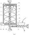
- FIG. 1 illustrates a schematic vertical cross-section of the device in an embodiment with two spiral supports and a screw conveyor inside a central tube;
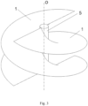
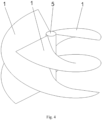
- a supporting structure for controlled gravity displacement of carried material includes two spiral supports 1.
- the spiral supports 1 form coils and have a common axis O.
- the origins of the spiral supports 1 are rotated relatively from each other by 180°, which corresponds to 360° divided by the number of the spiral supports 1 .
- Vertical distance between adjoining (arranged on top of each other) threads of the spiral supports 1 is 1.2m in the present case.
- the supporting structure includes a central tube 5 forming a central mounting of the spiral supports 1.
- the central tube 5 has its longitudinal axis identical to the spiral support 1 axis O.
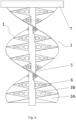
- Each of the spiral supports 1 comprises a system of mutually connected supporting elements 3. They are planar first type supporting elements 3A and second type supporting elements 3B.
- the planar supporting elements are arranged so that the first type supporting element 3A is oriented closer to the horizontal plane than the second type supporting element 3B.
- the supporting structure comprises a system of vents 6 for gas inflow to the upper surface of each spiral support 1 .
- the vents 6 have a form of through-holes on the area of the first type supporting elements 3B.
- the supporting structure is designed to be arranged in a rotary fashion inside an envelope 2.
- the supporting structure is provided on its upper end with a supporting ring 7 for rotary mounting inside the envelope 2 and for definition of the horizontal and vertical position of the supporting structure in relation to the envelope 2.
- the envelope 2 is provided with a supporting ring 7 counterpart 8 and a thermal insulation 15.
- the inner surface of the envelope 2 is provided with inwardly extending elements 14.
- the device for processing of the material comprising biodegradable waste includes said supporting structure, envelope 2 in which the supporting structure is arranged in a rotary fashion, a not illustrated actuator for rotation of the supporting structure inside the envelope 2, and a forced-draught blower 10 for gas blasting in the envelope 2 inner space. Further, the device includes a system of sensors for measuring of temperature, oxygen concentration, and moisture in the envelope 2 inner space.
- the device includes a conveyor 4 for material transport to the upper portion of the supporting structure, an upper spreader 13 for placing of the material in the upper portion of the supporting structure upon unloading from the conveyor 4, and a lower conveyor 11 for transport and filling of the material externally to the device.
- the conveyor 4 for material transport to the upper portion of the supporting structure is partially included in the central tube 5 and adapted to material transport via the central tube 5.
- the conveyor 4 has a form of a screw conveyor having its longitudinal axis identical to the spiral supports 1 axis O .
- the common spiral supports 1 axis O is oriented vertically in the device.
- a non-rotary base 12 is located under the central tube 5 in which the lower portion of the screw conveyor is fitted.
- the lower conveyor 11 of the material ends in the non-rotary base 12.
- In the lower portion of the device there is a rotary lower spreader 16 between the lower conveyor 11 of the material and the supporting structure. The lower spreader 16 spreads the material slid from the supporting structure so that it may be removed from the lower portion of the device.
- the material may be pushed to the lower conveyor 11 using the lower spreader 16.
- the lower conveyor 11 may transport the material to the non-rotary base 12 for reprocessing in the device.
- the processed material may be unloaded from the device by reverse operation of the lower conveyor 11, for example via the closable hole in the lower portion of the lower conveyor 11.
- a rotary partition 17 is arranged between the supporting structure and the lower spreader 16.
- the partition 17 is round in the top view and provided with two holes for the material to drop onto the lower spreader 16.
- the partition 11 is independently rotatable on the supporting structure as well as on the lower spreader 16.
- achieving of sanitary temperatures across the volume of the material being processed comprising the biodegradable waste is possible through the controlled aerobic fermentation in the device.
- it uses vertical orientation of the supporting structure carrying the material in separated layers 1.2m thick and controlled material aeration by distribution of temperatures, or oxygen contents within each layer.
- the aeration takes place through the blower 10 as well as natural convection in the material being heated.
- Fig. 1 The exemplary embodiment is shown in Fig. 1 , Fig. 3 , and Fig. 5 to Fig. 8 .
- a supporting structure for controlled gravity displacement of carried material includes two spiral supports 1 .
- the spiral supports 1 form coils and have a common axis O.
- the origins of the spiral supports 1 are rotated relatively from each other by 180°, which corresponds to 360° divided by the number of the spiral supports 1.
- Vertical distance between adjoining (arranged on top of each other) threads of the spiral supports 1 is 1.2m in the present case.
- the supporting structure includes a central tube 5 forming a central mounting of the spiral supports 1.
- the central tube 5 has its longitudinal axis identical to the spiral support 1 axis O.
- Each of the spiral supports 1 comprises a system of mutually connected supporting elements 1. They are planar first type supporting elements 3A and second type supporting elements 3B. The planar supporting elements are arranged so that the first type supporting element 3A is oriented closer to the horizontal plane than the second type supporting element 3B.
- the supporting structure comprises a system of vents 6 for gas inflow to the upper surface of each spiral support 1 .
- the vents 6 have a form of through-holes in the wall of the central tube 5.
- the vents 6 end 12cm above the upper surface of the spiral support 1 (which is 0.1 of the distance between adjoining threads of the spiral supports 1 ).
- the gas enters via them to the lower portion of the material resting on the spiral supports 1.
- the supporting structure is designed to be arranged in a rotary fashion inside an envelope 2.
- the supporting structure is provided on its upper end with a supporting ring 7 for rotary mounting inside the envelope 2 and for definition of the horizontal and vertical position of the supporting structure in relation to the envelope 2.
- the envelope 2 is provided with a supporting ring 7 counterpart 8 and a thermal insulation 15.
- the inner surface of the envelope 2 is provided with an inwardly extending elements 14.
- the device for processing of the material comprising biodegradable waste includes said supporting structure, the envelope 2 in which the supporting structure is arranged in a rotary fashion, an actuator for rotation of the supporting structure inside the envelope 2, and a forced-draught blower 10 for gas blasting in the envelope 2 inner space.
- the common spiral support 1 axis O is oriented vertically in the device.
- the forced-draught blower 10 output ends in the central tube 5 through the non-rotary base 12 located under the central tube 5.
- the device includes a system of sensors for measuring of temperature, oxygen concentration, and moisture in the envelope 2 inner space. In this case the envelope 2 is not self-supporting and it is therefore provided with a superior envelope 2 supporting frame 9.
- the device includes a conveyor 4 for material transport to the upper portion of the supporting structure, an upper spreader 13 for placing of the material in the upper portion of the supporting structure upon unloading from the conveyor 4.
- the conveyor 4 for material transport to the upper portion of the supporting structure is located outside the inner space of the envelope 2 and the conveyor is a belt one.
- a closable hopper in the upper wall (ceiling) of the envelope 2 is used for material entry from the conveyor 4 to the closed envelope 2.
- a rotary partition 17 is arranged under the supporting structure in the lower portion of the device.
- a lower spreader 16 is located under the rotary partition 17.
- the partition 17 is round in the top view and provided with two holes for the material to drop onto the lower spreader 16.
- the partition 17 is independently rotatable on the supporting structure as well as on the lower spreader 16.
- the lower spreader 16 is a rotary one and spreads the material slid from the supporting structure so that it may be removed from the lower portion of the device, e.g., via the closable cover in the lower portion of the device.
- Fig. 2 The exemplary embodiment is shown in Fig. 2 , Fig. 3 , and Fig. 9 .
Landscapes
- Chemical & Material Sciences (AREA)
- Engineering & Computer Science (AREA)
- Health & Medical Sciences (AREA)
- General Chemical & Material Sciences (AREA)
- Molecular Biology (AREA)
- Biochemistry (AREA)
- Biotechnology (AREA)
- Chemical Kinetics & Catalysis (AREA)
- Mechanical Engineering (AREA)
- Microbiology (AREA)
- Life Sciences & Earth Sciences (AREA)
- Organic Chemistry (AREA)
- Tropical Medicine & Parasitology (AREA)
- Processing Of Solid Wastes (AREA)
- Treatment Of Sludge (AREA)
- Fertilizers (AREA)
- Screw Conveyors (AREA)
Applications Claiming Priority (2)
| Application Number | Priority Date | Filing Date | Title |
|---|---|---|---|
| CZ2020-601A CZ309796B6 (cs) | 2020-11-05 | 2020-11-05 | Nosná konstrukce pro řízený gravitační posun neseného materiálu a zařízení s touto nosnou konstrukcí |
| PCT/CZ2021/050124 WO2022096042A1 (en) | 2020-11-05 | 2021-11-04 | Supporting structure for controlled gravity displacement of carried material and a device having the same |
Publications (3)
| Publication Number | Publication Date |
|---|---|
| EP4240677A1 EP4240677A1 (en) | 2023-09-13 |
| EP4240677B1 true EP4240677B1 (en) | 2024-11-20 |
| EP4240677C0 EP4240677C0 (en) | 2024-11-20 |
Family
ID=79171047
Family Applications (1)
| Application Number | Title | Priority Date | Filing Date |
|---|---|---|---|
| EP21835153.4A Active EP4240677B1 (en) | 2020-11-05 | 2021-11-04 | Supporting structure for controlled gravity displacement of carried material and a device having the same |
Country Status (4)
| Country | Link |
|---|---|
| EP (1) | EP4240677B1 (cs) |
| CZ (1) | CZ309796B6 (cs) |
| PL (1) | PL4240677T4 (cs) |
| WO (1) | WO2022096042A1 (cs) |
Families Citing this family (1)
| Publication number | Priority date | Publication date | Assignee | Title |
|---|---|---|---|---|
| CN116873260B (zh) * | 2023-08-21 | 2025-12-12 | 济俊消防科技有限公司 | 一种高效超细干粉灭火剂制作填充设备 |
Family Cites Families (10)
| Publication number | Priority date | Publication date | Assignee | Title |
|---|---|---|---|---|
| US3419377A (en) * | 1962-02-09 | 1968-12-31 | Garbage Service Company Inc | Method for treating organic and inorganic waste material |
| US4169878A (en) * | 1978-01-10 | 1979-10-02 | Etherington Alfred B | Helical composter |
| US6308529B1 (en) * | 1999-10-20 | 2001-10-30 | Morris & Associates, Inc. | Poultry chiller with open auger |
| EP1535888A1 (en) * | 2002-09-02 | 2005-06-01 | Kurita Water Industries Ltd. | Apparatus and method for producing matured compost-like substance |
| US6722490B1 (en) * | 2003-01-03 | 2004-04-20 | Morris & Associates, Inc. | Hanger bearing for use with an auger type poultry chiller |
| DE202007005577U1 (de) * | 2007-04-18 | 2007-06-14 | B. Strautmann & Söhne GmbH u. Co. KG | Vorrichtung zum Mischen, Belüften und Trocknen von Rohstoffen |
| WO2010151101A1 (en) * | 2009-06-26 | 2010-12-29 | Universiti Putra Malaysia | Novel in-vessel high rate composter |
| DE202011101177U1 (de) * | 2011-05-25 | 2012-08-28 | Trioliet Holding B.V. | Mischbehälter |
| CN106278436A (zh) * | 2016-10-15 | 2017-01-04 | 南宁绿智环保科技有限公司 | 一种固体有机物好氧加压高温发酵的方法及装置 |
| CN107192247A (zh) * | 2017-07-25 | 2017-09-22 | 魏满妹 | 一种螺旋式谷物循环电热风干燥装置 |
-
2020
- 2020-11-05 CZ CZ2020-601A patent/CZ309796B6/cs unknown
-
2021
- 2021-11-04 PL PL21835153.4T patent/PL4240677T4/pl unknown
- 2021-11-04 WO PCT/CZ2021/050124 patent/WO2022096042A1/en not_active Ceased
- 2021-11-04 EP EP21835153.4A patent/EP4240677B1/en active Active
Also Published As
| Publication number | Publication date |
|---|---|
| CZ309796B6 (cs) | 2023-10-18 |
| EP4240677C0 (en) | 2024-11-20 |
| PL4240677T4 (pl) | 2025-08-11 |
| WO2022096042A1 (en) | 2022-05-12 |
| PL4240677T3 (pl) | 2025-06-02 |
| CZ2020601A3 (cs) | 2022-05-18 |
| EP4240677A1 (en) | 2023-09-13 |
Similar Documents
| Publication | Publication Date | Title |
|---|---|---|
| US20070209417A1 (en) | Composting apparatus with internal transport system | |
| AU678029B2 (en) | Digester for converting organic material into compost | |
| US6065224A (en) | Device and process for the aerobic treatment of organic substances | |
| US3114622A (en) | Waste material converter and method of digesting waste | |
| US5258306A (en) | Silo composting apparatus | |
| US12173236B2 (en) | Apparatus for the production of biochar by the pyrolysis of biomass | |
| US3055744A (en) | Apparatus for the fermentation of solid organic waste materials for making compost | |
| AU2001282725A1 (en) | A composting apparatus with internal transport system | |
| EP4240677B1 (en) | Supporting structure for controlled gravity displacement of carried material and a device having the same | |
| WO2008014369A2 (en) | Vertical composter with leachate retention system | |
| BRPI0619787A2 (pt) | método e aparelho para secar material orgánico | |
| EP4056543B1 (en) | Composting apparatus and method of processing organic matter | |
| KR20120065888A (ko) | 파리 유충을 이용한 축분 퇴비화 시스템 | |
| NZ538626A (en) | Vertical composting apparatus including processing zones | |
| SU1789522A1 (en) | Bird droppings reprocessing apparatus | |
| AU2006238400B2 (en) | Multi-staged composting | |
| WO2010151101A1 (en) | Novel in-vessel high rate composter | |
| KR101203100B1 (ko) | 가축분뇨의 퇴비화설비 및 이를 사용한 가축분뇨의 퇴비화방법 | |
| JPH0977580A (ja) | 堆肥醗酵装置 |
Legal Events
| Date | Code | Title | Description |
|---|---|---|---|
| STAA | Information on the status of an ep patent application or granted ep patent |
Free format text: STATUS: UNKNOWN |
|
| STAA | Information on the status of an ep patent application or granted ep patent |
Free format text: STATUS: THE INTERNATIONAL PUBLICATION HAS BEEN MADE |
|
| PUAI | Public reference made under article 153(3) epc to a published international application that has entered the european phase |
Free format text: ORIGINAL CODE: 0009012 |
|
| STAA | Information on the status of an ep patent application or granted ep patent |
Free format text: STATUS: REQUEST FOR EXAMINATION WAS MADE |
|
| 17P | Request for examination filed |
Effective date: 20230602 |
|
| AK | Designated contracting states |
Kind code of ref document: A1 Designated state(s): AL AT BE BG CH CY CZ DE DK EE ES FI FR GB GR HR HU IE IS IT LI LT LU LV MC MK MT NL NO PL PT RO RS SE SI SK SM TR |
|
| DAV | Request for validation of the european patent (deleted) | ||
| DAX | Request for extension of the european patent (deleted) | ||
| GRAP | Despatch of communication of intention to grant a patent |
Free format text: ORIGINAL CODE: EPIDOSNIGR1 |
|
| STAA | Information on the status of an ep patent application or granted ep patent |
Free format text: STATUS: GRANT OF PATENT IS INTENDED |
|
| RIC1 | Information provided on ipc code assigned before grant |
Ipc: C05F 17/979 20200101ALI20240528BHEP Ipc: C05F 17/60 20200101ALI20240528BHEP Ipc: C05F 17/20 20200101ALI20240528BHEP Ipc: C05F 17/95 20200101ALI20240528BHEP Ipc: B65G 33/18 20060101AFI20240528BHEP |
|
| INTG | Intention to grant announced |
Effective date: 20240612 |
|
| GRAS | Grant fee paid |
Free format text: ORIGINAL CODE: EPIDOSNIGR3 |
|
| GRAA | (expected) grant |
Free format text: ORIGINAL CODE: 0009210 |
|
| STAA | Information on the status of an ep patent application or granted ep patent |
Free format text: STATUS: THE PATENT HAS BEEN GRANTED |
|
| AK | Designated contracting states |
Kind code of ref document: B1 Designated state(s): AL AT BE BG CH CY CZ DE DK EE ES FI FR GB GR HR HU IE IS IT LI LT LU LV MC MK MT NL NO PL PT RO RS SE SI SK SM TR |
|
| REG | Reference to a national code |
Ref country code: GB Ref legal event code: FG4D |
|
| REG | Reference to a national code |
Ref country code: CH Ref legal event code: EP |
|
| REG | Reference to a national code |
Ref country code: DE Ref legal event code: R096 Ref document number: 602021022207 Country of ref document: DE |
|
| REG | Reference to a national code |
Ref country code: IE Ref legal event code: FG4D |
|
| U01 | Request for unitary effect filed |
Effective date: 20241219 |
|
| U07 | Unitary effect registered |
Designated state(s): AT BE BG DE DK EE FI FR IT LT LU LV MT NL PT RO SE SI Effective date: 20250110 |
|
| PG25 | Lapsed in a contracting state [announced via postgrant information from national office to epo] |
Ref country code: IS Free format text: LAPSE BECAUSE OF FAILURE TO SUBMIT A TRANSLATION OF THE DESCRIPTION OR TO PAY THE FEE WITHIN THE PRESCRIBED TIME-LIMIT Effective date: 20250320 Ref country code: HR Free format text: LAPSE BECAUSE OF FAILURE TO SUBMIT A TRANSLATION OF THE DESCRIPTION OR TO PAY THE FEE WITHIN THE PRESCRIBED TIME-LIMIT Effective date: 20241120 |
|
| PG25 | Lapsed in a contracting state [announced via postgrant information from national office to epo] |
Ref country code: ES Free format text: LAPSE BECAUSE OF FAILURE TO SUBMIT A TRANSLATION OF THE DESCRIPTION OR TO PAY THE FEE WITHIN THE PRESCRIBED TIME-LIMIT Effective date: 20241120 |
|
| PG25 | Lapsed in a contracting state [announced via postgrant information from national office to epo] |
Ref country code: NO Free format text: LAPSE BECAUSE OF FAILURE TO SUBMIT A TRANSLATION OF THE DESCRIPTION OR TO PAY THE FEE WITHIN THE PRESCRIBED TIME-LIMIT Effective date: 20250220 |
|
| PG25 | Lapsed in a contracting state [announced via postgrant information from national office to epo] |
Ref country code: GR Free format text: LAPSE BECAUSE OF FAILURE TO SUBMIT A TRANSLATION OF THE DESCRIPTION OR TO PAY THE FEE WITHIN THE PRESCRIBED TIME-LIMIT Effective date: 20250221 |
|
| PG25 | Lapsed in a contracting state [announced via postgrant information from national office to epo] |
Ref country code: RS Free format text: LAPSE BECAUSE OF FAILURE TO SUBMIT A TRANSLATION OF THE DESCRIPTION OR TO PAY THE FEE WITHIN THE PRESCRIBED TIME-LIMIT Effective date: 20250220 |
|
| PG25 | Lapsed in a contracting state [announced via postgrant information from national office to epo] |
Ref country code: SM Free format text: LAPSE BECAUSE OF FAILURE TO SUBMIT A TRANSLATION OF THE DESCRIPTION OR TO PAY THE FEE WITHIN THE PRESCRIBED TIME-LIMIT Effective date: 20241120 |
|
| PG25 | Lapsed in a contracting state [announced via postgrant information from national office to epo] |
Ref country code: SK Free format text: LAPSE BECAUSE OF FAILURE TO SUBMIT A TRANSLATION OF THE DESCRIPTION OR TO PAY THE FEE WITHIN THE PRESCRIBED TIME-LIMIT Effective date: 20241120 |
|
| PG25 | Lapsed in a contracting state [announced via postgrant information from national office to epo] |
Ref country code: CZ Free format text: LAPSE BECAUSE OF FAILURE TO SUBMIT A TRANSLATION OF THE DESCRIPTION OR TO PAY THE FEE WITHIN THE PRESCRIBED TIME-LIMIT Effective date: 20241120 |
|
| PLBE | No opposition filed within time limit |
Free format text: ORIGINAL CODE: 0009261 |
|
| STAA | Information on the status of an ep patent application or granted ep patent |
Free format text: STATUS: NO OPPOSITION FILED WITHIN TIME LIMIT |
|
| 26N | No opposition filed |
Effective date: 20250821 |
|
| U20 | Renewal fee for the european patent with unitary effect paid |
Year of fee payment: 5 Effective date: 20251027 |
|
| REG | Reference to a national code |
Ref country code: CH Ref legal event code: U11 Free format text: ST27 STATUS EVENT CODE: U-0-0-U10-U11 (AS PROVIDED BY THE NATIONAL OFFICE) Effective date: 20260105 |
|
| PGFP | Annual fee paid to national office [announced via postgrant information from national office to epo] |
Ref country code: GB Payment date: 20251229 Year of fee payment: 5 |
|
| PGFP | Annual fee paid to national office [announced via postgrant information from national office to epo] |
Ref country code: MC Payment date: 20251229 Year of fee payment: 5 |
|
| PGFP | Annual fee paid to national office [announced via postgrant information from national office to epo] |
Ref country code: IE Payment date: 20251229 Year of fee payment: 5 |
|
| PGFP | Annual fee paid to national office [announced via postgrant information from national office to epo] |
Ref country code: PL Payment date: 20251027 Year of fee payment: 5 |
|
| PGFP | Annual fee paid to national office [announced via postgrant information from national office to epo] |
Ref country code: CH Payment date: 20260105 Year of fee payment: 5 |