EP4240620B1 - Antriebsmechanismus zum bewegen eines wischarms - Google Patents
Antriebsmechanismus zum bewegen eines wischarms Download PDFInfo
- Publication number
- EP4240620B1 EP4240620B1 EP20803823.2A EP20803823A EP4240620B1 EP 4240620 B1 EP4240620 B1 EP 4240620B1 EP 20803823 A EP20803823 A EP 20803823A EP 4240620 B1 EP4240620 B1 EP 4240620B1
- Authority
- EP
- European Patent Office
- Prior art keywords
- drive mechanism
- biasing element
- axis
- shaft
- cooperate
- Prior art date
- Legal status (The legal status is an assumption and is not a legal conclusion. Google has not performed a legal analysis and makes no representation as to the accuracy of the status listed.)
- Active
Links
Images
Classifications
-
- B—PERFORMING OPERATIONS; TRANSPORTING
- B60—VEHICLES IN GENERAL
- B60S—SERVICING, CLEANING, REPAIRING, SUPPORTING, LIFTING, OR MANOEUVRING OF VEHICLES, NOT OTHERWISE PROVIDED FOR
- B60S1/00—Cleaning of vehicles
- B60S1/02—Cleaning windscreens, windows or optical devices
- B60S1/04—Wipers or the like, e.g. scrapers
- B60S1/32—Wipers or the like, e.g. scrapers characterised by constructional features of wiper blade arms or blades
- B60S1/34—Wiper arms; Mountings therefor
- B60S1/3486—Means to allow blade to follow curvature of the screen (i.e. rotation along longitudinal axis of the arm)
-
- B—PERFORMING OPERATIONS; TRANSPORTING
- B60—VEHICLES IN GENERAL
- B60S—SERVICING, CLEANING, REPAIRING, SUPPORTING, LIFTING, OR MANOEUVRING OF VEHICLES, NOT OTHERWISE PROVIDED FOR
- B60S1/00—Cleaning of vehicles
- B60S1/02—Cleaning windscreens, windows or optical devices
- B60S1/04—Wipers or the like, e.g. scrapers
- B60S1/32—Wipers or the like, e.g. scrapers characterised by constructional features of wiper blade arms or blades
- B60S1/34—Wiper arms; Mountings therefor
- B60S1/3488—Means for mounting wiper arms onto the vehicle
- B60S1/3493—Means for mounting the wiper shaft in the wiper bearing
Definitions
- the invention relates to a drive mechanism configured for moving a wiper arm. It also concerns a wiping system for a windshield of a vehicle including said drive mechanism.
- the invention concerns all sorts of vehicles that use wipers (cars, trucks,).
- a drive mechanism for rotating a wiper arm around a wiper shaft of the vehicle is known in the art. It is also known to longitudinally rotate said wiper arm to maintain an orientation of a rubber blade of the wiper arm with respect to a windshield surface of a vehicle.
- an attack angle of a tip of the rubber blade should be close to the normal of the windshield surface, i.e. sensibly perpendicular to the windshield surface at the contact point. This should be the case for all positions of the rubber blade in both wiping directions.
- the wiper arm and the rubber blade may be susceptible to chatter and become noisy when the rubber blade becomes worn.
- the wiper arm and the rubber blade have a twisting angle from the heel to the tip that is not balanced. This may contribute to poor wipe quality.
- Wiper arms have already been proposed to adapt the attack angle of the rubber blade as for example in EP 1 908 654 A1 .
- the described system is particularly complex and includes devices such as gear and endless screws that are particularly expensive and complex to assemble. Due to its complexity, it appears difficult to have correct durability without failures.
- US2009/025173 discloses a wiper having a rotation control mechanism including a primary shaft driven in an alternating axially rotating manner, a drive carrier fixed to the primary shaft, a secondary shaft mounted in an axially rotatable manner in relation to the drive carrier, a fixed cam provided with a specific profiled element, and a control element which is fixed to the secondary shaft and cooperates in a sliding manner with the cam profiled element during the displacement of the drive carrier in relation to the fixed cam, where the sliding of the control element along the cam profiled element control the axial pivoting of the secondary shaft.
- the present invention relates to a drive mechanism configured for moving a wiper arm, the drive mechanism comprising:
- This arrangement allows modifying the orientation of a rubber blade included in the wiper arm based on the position of the wiper arm in relation to the windshield surface curved shape. This is particularly advantageous when the windshield curvature is particularly important.
- the drive mechanism can be used on the passenger side and on the driver side of a vehicle with all curved windshield definitions provided that the biasing element is adapted to said curvature.
- Moving the radial pin with the biasing element constitutes a simple and reliable mechanism, as the constraints on the radial pin are low. Indeed, the inclination adjustment assembly rotates together with the rotating assembly and the displacements of the inclination shaft with respect to the rotating assembly are limited.
- the radial pin is extending according to a pin axis extending transversally to the secondary axis.
- the inclination adjustment assembly comprises a cylindrical mounting element configured to be attached around the inclination shaft and that includes a fastening location for the radial pin.
- the radial pin comprises a spherical segment configured to cooperate with the biasing element.
- said spherical segment is comprised in a cam roller of the radial pin.
- the drive mechanism is thus durable.
- the pin axis corresponds to a revolution axis of the spherical segment.
- the radial pin comprises a central part configured to be attached to the fastening location.
- the biasing element is a cam plate extending transversally to the primary axis and presenting an aperture configured to receive the radial pin.
- the aperture corresponds to a through opening in the cam plate.
- the drive mechanism comprises simple components, which implies that it is cost effective and reliable.
- the aperture presents a closed contour located partially around the primary axis to allow a displacement of the radial pin between two end positions of the rotating assembly around the primary axis.
- the aperture presents a cooperating surface designed for cooperating with the radial pin, said cooperating surface extending parallel to the primary axis.
- the support assembly comprises a cylindrical intermediate part on which the biasing element is attached, the cylindrical intermediate part being configured to be mounted on a guiding support of the wiper shaft in a fixed manner.
- the cylindrical intermediate part comprises a bearing element for cooperating with the wiper shaft.
- the guiding support is configured to be attached to a vehicle and serves as a bearing portion for the wiper shaft.
- the cylindrical intermediate part comprises radial retaining walls configured to cooperate with complementary radial retaining walls of the biasing element to prevent a rotation according to the primary axis.
- the radial retaining walls are located on a lug or a notch of the cylindrical intermediate part extending radially and the complementary radial retaining walls are located in a complementary notch or respectively complementary lug of the biasing element.
- the cylindrical intermediate part comprises radial blocking walls configured to cooperate with complementary blocking walls of the guiding support to prevent a rotation according to the primary axis.
- the rotating assembly comprises a protective casing wherein the biasing element and the radial pin are located, the protective casing presenting a cylindrical opening for accommodating the inclination shaft, the at least one cylindrical bearing being located inside said cylindrical opening.
- the protective casing comprises two parts configured to be secured together.
- the rotating assembly comprises a gripping part configured to fix in rotation the rotating assembly to the wiper shaft.
- the gripping part is included in or configured to cooperate with the protective casing.
- the present invention also concerns a wiping system comprising a drive mechanism as detailed above and a wiper arm including a holder and a rubber blade attached to said holder, the biasing element being configured to adapt an orientation of the rubber blade with regard to a windshield surface of a vehicle on which the wiping system is mounted.
- the inclination shaft is configured for moving the holder around the secondary axis following the actuation of the biasing element.
- the biasing element is geometrically designed with respect to a curvature of the windshield surface so that an attack angle of the rubber blade remains under a predefined value with regard to the normal at a contact point across a contact length of the rubber blade with the windshield surface.
- the attack angle is defined, for each section of the rubber blade as the attack angle between the normal at the contact point of a tip of the rubber blade and a central axis of the corresponding section of the rubber blade defined between the tip and a center of the heel of the rubber blade.
- the attack angle should be considered according to both directions, i.e. as positive and negative with respect to the normal.
- said predefined value is inferior to 20°, preferably inferior to 15° and in particular inferior to 10°. In other words, it corresponds to 40°, 30° and 20° angle intervals around the normal.
- the holder comprises a coupling part configured to be mounted fixed in rotation on the inclination shaft, an arm front designed to attach the rubber blade and a retainer linking the coupling part and the arm front.
- the coupling part includes a cooperating annular element configured to cooperate with the protective casing according to a rotation around the inclination shaft.
- the holder comprises an articulation device configured to enable a rotation of the retainer with respect to the coupling part according to an unfolding axis extending transversally to the secondary axis.
- the articulation device comprises a binding element configured to cooperate with a retaining spring of the holder, the retaining spring being configured to be attached to the arm front and to apply a constraint to rotate the retainer in direction of the windshield surface around the unfolding axis.
- the binding element comprises a hook configured to attach a corresponding part of the retaining spring.
- the binding element is configured to cooperate with a support pin of the coupling part extending parallel to the unfolding axis.
- the present invention also concerns a wiping system as disclosed above.
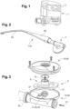
- a vehicle 1 comprises two wiping systems 3.
- Each wiping system 3 comprises a drive mechanism 5 as illustrated in figures 2 to 8 .
- the drive mechanism 5 is configured for moving a wiper arm 7 of the wiping system 3, the drive mechanism 5 comprising a support assembly 9 configured to cooperate with a wiper shaft 11 of the vehicle 1 extending according to a primary axis 13 to allow a reciprocating rotation of the wiper shaft 11 with respect the support assembly 9 along the primary axis 13.
- the drive mechanism 5 comprises a rotating assembly 15 configured to be mounted in a rotationally fixed manner with the wiper shaft 11, the rotating assembly 15 including at least one cylindrical bearing 17 extending according to a secondary axis 19, the secondary axis 19 being transverse to the primary axis 13.
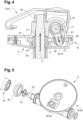
- the drive mechanism 5 also comprises an inclination adjustment assembly 21, as illustrated in figure 7 , including an inclination shaft 23 configured to be fixed to the wiper arm 7 and to cooperate with the at least one cylindrical bearing 17 so as to be allowed to rotate according to the secondary axis 19.
- the inclination adjustment assembly 21 further includes a radial pin 25 mounted on the inclination shaft 23 and configured to cooperate with a biasing element 27 of the support assembly 9, the biasing element 27 being configured to rotate the inclination shaft 23 depending on a displacement of the rotating assembly 15 according to the primary axis 13 with respect to the support assembly 9.
- the radial pin 25 is extending according to a pin axis 29 extending transversally to the secondary axis 19.
- the inclination adjustment assembly 21 comprises a cylindrical mounting element 31 configured to be attached around the inclination shaft 23 and that includes a fastening location 33 for the radial pin 25.
- the radial pin 25 comprises a spherical segment 35 configured to cooperate with the biasing element 27. Said spherical segment 35 is comprised in a cam roller of the radial pin 25.
- the pin axis 29 corresponds to a revolution axis of the spherical segment 35.
- the radial pin 25 comprises a central part 37 configured to be attached to the fastening location 33.
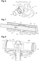
- the biasing element 27 is a cam plate extending transversally to the primary axis 13 and presenting an aperture 39 configured to receive the radial pin 25.
- the aperture 39 corresponds to a through opening in the cam plate.
- the aperture 39 presents a closed contour located partially around the primary axis 13 to allow a displacement of the radial pin 25 between two end positions of the rotating assembly 15 around the primary axis 13.
- the aperture 39 presents a cooperating surface 41 designed for cooperating with the radial pin 25, said cooperating surface 41 extending parallel to the primary axis 13.
- the pin 25 follows the entire cooperating surface 41 during a movement of the wiper from a start to end and back to start position and the spherical segment 35 rolls on the edge of the aperture 39.
- the support assembly 9 comprises a cylindrical intermediate part 43 on which the biasing element 27 is attached, the cylindrical intermediate part 43 being configured to be mounted on a guiding support 45 of the wiper shaft 11 in a fixed manner.
- the cylindrical intermediate part 43 comprises a bearing element 47 for cooperating with the wiper shaft 11.
- the guiding support 45 is comprised in the vehicle 1 and serves as a bearing portion for the wiper shaft 11.
- the cylindrical intermediate part 43 comprises radial retaining walls 49 configured to cooperate with complementary radial retaining walls 51 of the biasing element 27 to prevent a rotation according to the primary axis 13.
- the radial retaining walls 49 are located on a lug or a notch of the cylindrical intermediate part 43 extending radially and the complementary radial retaining walls 51 are located in a complementary notch or respectively complementary lug of the biasing element 27.
- the cylindrical intermediate part 43 comprises radial blocking walls 53 configured to cooperate with complementary blocking walls of the guiding support 45 to prevent a rotation according to the primary axis 13.
- the rotating assembly 15 comprises a protective casing 55 wherein the biasing element 27 and the radial pin 25 are located, the protective casing 55 presenting a cylindrical opening 57 for accommodating the inclination shaft 23, the at least one cylindrical bearing 17 being located inside said cylindrical opening 57.
- the protective casing 55 comprises two parts configured to be secured together.
- the rotating assembly 15 comprises a gripping part 59 configured to fix in rotation the rotating assembly 15 to the wiper shaft 11.
- the gripping part 59 is included in or configured to cooperate with the protective casing 55.
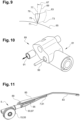
- the wiping system 3 comprises a drive mechanism 5 as detailed above and the wiper arm 7.
- the wiper arm 7 includes a holder 61 and a rubber blade 63 attached to said holder 61 and schematically represented in figure 9 , the biasing element 27 being configured to adapt an orientation of the rubber blade 63 with regard to a windshield surface 65 of a vehicle 1 on which the wiping system 3 is mounted.
- the inclination shaft 23 is configured for moving the holder 61 around the secondary axis 19 following the actuation of the biasing element 27.
- the biasing element 27 is geometrically designed with respect to a curvature of the windshield surface 65 so that an attack angle 67 of the rubber blade 63 remains under a predefined value with regard to the normal 69 at a contact point 71 across a contact length 73 of the rubber blade 63 with the windshield surface 65.
- the attack angle 67 is defined, for each section of the rubber blade 63 as the attack angle 67 between the normal 69 at the contact point 71 of a tip 75 of the rubber blade 63 and a central axis 77 of the corresponding section of the rubber blade 63 defined between the tip 75 and a center of the heel 79 of the rubber blade 63.
- the attack angle 67 should be considered according to both directions, i.e. as positive and negative with respect to the normal 69.
- Said predefined value is inferior to 20°, preferably inferior to 15° and in particular inferior to 10°. In other words, it corresponds to 40°, 30° and 20° angle intervals around the normal 69.
- the holder 61 comprises a coupling part 81 configured to be mounted fixed in rotation on the inclination shaft 23, an arm front 83 designed to attach the rubber blade 63 and a retainer 85 linking the coupling part 81 and the arm front 83.
- the coupling part 81 includes a cooperating annular element 87 configured to cooperate with the protective casing 55 according to a rotation around the inclination shaft 23.
- the holder 61 comprises an articulation device 89 configured to enable a rotation of the retainer 85 with respect to the coupling part 81 according to an unfolding axis 91 extending transversally to the secondary axis 19.
- the articulation device 89 comprises a binding element 93 configured to cooperate with a retaining spring 95 of the holder 61, the retaining spring 95 being configured to be attached to the arm front 83 and to apply a constraint to rotate the retainer 85 in direction of the windshield surface 65 around the unfolding axis 91.
- the binding element 93 comprises a hook 97 configured to attach a corresponding part of the retaining spring 95.
- the binding element 93 is configured to cooperate with a support pin 99 of the coupling part 81 extending parallel to the unfolding axis 91.
- the drive mechanism 5 can be used on the passenger side and on the driver side of a vehicle 1 with all curved windshield definitions provided that the biasing element 27 is adapted to said curvature.
- Moving the radial pin 25 with the biasing element 27 constitutes a simple and reliable mechanism, as the constraints on the radial pin 27 are low. Indeed, the inclination adjustment assembly 21 rotates together with the rotating assembly 15 and the displacements of the inclination shaft 23 with respect to the rotating assembly 15 are limited.
- the drive mechanism 5 comprises simple components, which implies that it is cost effective and reliable.
Landscapes
- Engineering & Computer Science (AREA)
- Mechanical Engineering (AREA)
- Transmission Devices (AREA)
Claims (12)
- Antriebsmechanismus (5), der zum Bewegen eines Wischerarms (7) konfiguriert ist, wobei der Antriebsmechanismus (5) umfasst:- eine Trägerbaugruppe (9), die so konfiguriert ist, dass sie mit einer Wischerwelle (11) zusammenwirkt, die sich gemäß einer Primärachse (13) erstreckt, um eine Drehung der Wischerwelle (11) in Bezug auf die Trägerbaugruppe (9) gemäß der Primärachse (13) zu ermöglichen,- eine Drehbaugruppe (15), die so konfiguriert ist, dass sie drehfest mit der Wischerwelle (11) montiert werden kann, wobei die Drehbaugruppe (15) mindestens ein zylindrisches Lager (17) beinhaltet, das sich gemäß einer Sekundärachse (19) erstreckt, wobei die Sekundärachse (19) quer zur Primärachse (13) verläuft,- eine Neigungseinstellbaugruppe (21), die eine Neigungswelle (23) beinhaltet, die so konfiguriert ist, dass sie am Wischerarm (7) befestigt werden und mit dem mindestens einen zylindrischen Lager (17) so zusammenwirken kann, dass es ihr möglich ist, gemäß der Sekundärachse (19) zu drehen, wobei die Neigungseinstellbaugruppe (21) weiter einen radialen Stift (25) beinhaltet, der an der Neigungswelle (23) montiert und so konfiguriert ist, dass er mit einem Vorspannelement (27) der Trägerbaugruppe (9) zusammenwirkt, wobei das Vorspannelement (27) so konfiguriert ist, dass es die Neigungswelle (23) abhängig von einer Verlagerung der Drehbaugruppe (15) gemäß der Primärachse (13) in Bezug auf die Trägerbaugruppe (9) dreht,dadurch gekennzeichnet, dassdie Trägerbaugruppe (9) ein zylindrisches Zwischenteil (43) umfasst, an dem das Vorspannelement (27) angebracht ist, wobei das zylindrische Zwischenteil (43) so konfiguriert ist, dass es fest an einem Führungsträger (45) der Wischerwelle (11) montiert werden kann,wobei das zylindrische Zwischenteil (43) radiale Rückhaltewände (49) umfasst, die so konfiguriert sind, dass sie mit komplementären radialen Rückhaltewänden (51) des Vorspannelements (27) zusammenwirken, um eine Drehung gemäß der Primärachse (13) zu verhindern.
- Antriebsmechanismus (5) nach Anspruch 1, wobei der radiale Stift (25) ein Kugelsegment (35) umfasst, das so konfiguriert ist, dass es mit dem Vorspannelement (27) zusammenwirkt.
- Antriebsmechanismus (5) nach Anspruch 2, wobei das Kugelsegment (35) in einer Nockenwalze des radialen Stifts (25) umfasst ist.
- Antriebsmechanismus (5) nach einem der Ansprüche 1 bis 3, wobei das Vorspannelement (27) eine Nockenplatte ist, die sich quer zur Primärachse (13) erstreckt und einen Durchbruch (39) aufweist, der so konfiguriert ist, dass er den radialen Stift (25) aufnimmt.
- Antriebsmechanismus (5) nach Anspruch 4, wobei der Durchbruch (39) eine geschlossene Kontur aufweist, die sich teilweise um die Primärachse (13) herum befindet, um eine Verlagerung des radialen Stifts (25) zwischen zwei Endpositionen der Drehbaugruppe (15) um die Primärachse (13) herum zu ermöglichen.
- Antriebsmechanismus (5) nach einem der Ansprüche 1 bis 5, wobei die Drehbaugruppe (15) ein Schutzgehäuse (55) umfasst, in dem sich das Vorspannelement (27) und der radiale Stift (25) befinden, wobei das Schutzgehäuse (55) eine zylindrische Öffnung (57) zum Aufnehmen der Neigungswelle (23) aufweist, wobei sich das mindestens eine zylindrische Lager (17) innerhalb der zylindrischen Öffnung (57) befindet.
- Antriebsmechanismus (5) nach einem der Ansprüche 1 bis 6, wobei die Drehbaugruppe (15) ein Greifteil (59) umfasst, das so konfiguriert ist, dass es die Drehbaugruppe (15) drehfest an der Wischerwelle (11) befestigt.
- Wischsystem (3), das einen Antriebsmechanismus (5) nach einem der Ansprüche 1 bis 7 und einen Wischerarm (7) umfasst, der einen Halter (61) und ein an dem Halter (61) angebrachtes Gummiblatt (63) beinhaltet, wobei das Vorspannelement (27) so konfiguriert ist, dass es eine Ausrichtung des Gummiblatts (63) in Bezug auf eine Windschutzscheibenoberfläche (65) eines Fahrzeugs (1), an dem das Wischsystem (3) montiert ist, anpasst.
- Wischsystem (3) nach Anspruch 8, wobei das Vorspannelement (27) in Bezug auf eine Krümmung der Windschutzscheibenoberfläche (65) geometrisch so gestaltet ist, dass ein Anstellwinkel (67) des Gummiblatts (63) in Bezug auf die Normale (69) an einem Kontaktpunkt (71) über eine Kontaktlänge (73) des Gummiblatts (63) mit der Windschutzscheibenoberfläche (65) hinweg unter einem vordefinierten Wert bleibt.
- Wischsystem (3) nach einem der Ansprüche 8 oder 9, wobei der Halter (61) ein Kopplungsteil (81), das so konfiguriert ist, dass es drehfest an der Neigungswelle (23) montiert werden kann, eine Armvorderseite (83), die so gestaltet ist, dass sie das Gummiblatt (63) anbringt, und eine Rückhalterung (85) umfasst, die das Kopplungsteil (81) und die Armvorderseite (83) miteinander verbindet.
- Wischsystem (3) nach Anspruch 10, wobei der Halter (61) eine Gelenkvorrichtung (89) umfasst, die so konfiguriert ist, dass sie eine Drehung der Rückhalterung (85) in Bezug auf das Kopplungsteil (81) gemäß einer Entfaltungsachse (91), die sich quer zur Sekundärachse (19) erstreckt, ermöglicht.
- Wischsystem (3) nach Anspruch 11, wobei die Gelenkvorrichtung (89) ein Bindeelement (93) umfasst, das so konfiguriert ist, dass es mit einer Rückhaltefeder (95) des Halters (61) zusammenwirkt, wobei die Rückhaltefeder (95) so konfiguriert ist, dass sie an der Armvorderseite (83) angebracht werden und eine Kraft anlegen kann, um die Rückhalterung (85) in Richtung der Windschutzscheibenoberfläche (65) um die Entfaltungsachse (91) herum zu drehen.
Applications Claiming Priority (1)
| Application Number | Priority Date | Filing Date | Title |
|---|---|---|---|
| PCT/EP2020/081491 WO2022096132A1 (en) | 2020-11-09 | 2020-11-09 | Drive mechanism for moving a wiper arm |
Publications (3)
| Publication Number | Publication Date |
|---|---|
| EP4240620A1 EP4240620A1 (de) | 2023-09-13 |
| EP4240620C0 EP4240620C0 (de) | 2024-08-28 |
| EP4240620B1 true EP4240620B1 (de) | 2024-08-28 |
Family
ID=73198325
Family Applications (1)
| Application Number | Title | Priority Date | Filing Date |
|---|---|---|---|
| EP20803823.2A Active EP4240620B1 (de) | 2020-11-09 | 2020-11-09 | Antriebsmechanismus zum bewegen eines wischarms |
Country Status (3)
| Country | Link |
|---|---|
| US (1) | US20240001890A1 (de) |
| EP (1) | EP4240620B1 (de) |
| WO (1) | WO2022096132A1 (de) |
Citations (1)
| Publication number | Priority date | Publication date | Assignee | Title |
|---|---|---|---|---|
| DE1014860B (de) * | 1955-06-23 | 1957-08-29 | Gen Motors Corp | Scheibenwischer |
Family Cites Families (8)
| Publication number | Priority date | Publication date | Assignee | Title |
|---|---|---|---|---|
| US2692186A (en) * | 1953-06-25 | 1954-10-19 | Kamlet Jonas | Manufacture of sodium fluoride low in silica content |
| US3019469A (en) * | 1958-01-31 | 1962-02-06 | Gen Motors Corp | Windshield cleaner |
| DE3638159A1 (de) * | 1986-11-08 | 1988-05-11 | Bosch Gmbh Robert | Pendel-wischvorrichtung fuer scheiben von kraftfahrzeugen |
| US4800610A (en) * | 1987-06-12 | 1989-01-31 | Nippon Wiper Blade Co., Ltd. | Windshield wiper |
| FR2742114B1 (fr) | 1995-12-07 | 1998-01-09 | Valeo Systemes Dessuyage | Dispositif d'essuyage pour une vitre de vehicule automobile |
| FR2746355B1 (fr) * | 1996-03-22 | 1998-04-30 | Valeo Systemes Dessuyage | Essuie-glace de vehicule automobile muni d'un dispositif d'orientation |
| FR2897408B1 (fr) | 2006-02-13 | 2009-02-27 | Valeo Systemes Dessuyage | Mecanisme de commande en rotation notamment pour dispositif d'essuyage de vehicule automobile |
| DE102007036785A1 (de) | 2006-10-04 | 2008-04-10 | Robert Bosch Gmbh | Scheibenwischervorrichtung |
-
2020
- 2020-11-09 EP EP20803823.2A patent/EP4240620B1/de active Active
- 2020-11-09 US US18/035,469 patent/US20240001890A1/en not_active Abandoned
- 2020-11-09 WO PCT/EP2020/081491 patent/WO2022096132A1/en not_active Ceased
Patent Citations (1)
| Publication number | Priority date | Publication date | Assignee | Title |
|---|---|---|---|---|
| DE1014860B (de) * | 1955-06-23 | 1957-08-29 | Gen Motors Corp | Scheibenwischer |
Also Published As
| Publication number | Publication date |
|---|---|
| EP4240620C0 (de) | 2024-08-28 |
| EP4240620A1 (de) | 2023-09-13 |
| WO2022096132A1 (en) | 2022-05-12 |
| US20240001890A1 (en) | 2024-01-04 |
Similar Documents
| Publication | Publication Date | Title |
|---|---|---|
| US5182957A (en) | Drive unit, in particular for a windshield wiper system on a motor vehicle | |
| US5007131A (en) | Blade carrying assembly for a windshield wiper including a lock | |
| US6286176B1 (en) | Windshield wiper connector | |
| US20070199174A1 (en) | Adapter Hingedly Connecting A Wiper Blade To A Wiper Arm | |
| US20020002755A1 (en) | Articulation system between windscreen wiper components | |
| AU2010227767A1 (en) | Connecting device for the articulate connection of a wiper arm to a wiper blade according to a side-lock principle | |
| CN101300159A (zh) | 用于汽车挡风玻璃的雨刷器设备 | |
| JPH11500086A (ja) | 自動車のガラスのスクリーンワイパー装置 | |
| EP4240620B1 (de) | Antriebsmechanismus zum bewegen eines wischarms | |
| EP1834851B1 (de) | Wischersystem | |
| US5819363A (en) | Windshield wiper for a window with a constant radius of curvature | |
| KR101245363B1 (ko) | 오조립 방지 구조가 구비된 와이퍼 블레이드 장치 | |
| US20120117747A1 (en) | Pivot body for windshield wiper system | |
| US6000092A (en) | Wiper device with elastic torsion load absorber | |
| US5894627A (en) | Wiper device with elastic bush for absorbing excess load | |
| EP0477803B1 (de) | Scherenförmiger Scheibenwischer für Kraftfahrzeuge | |
| CN108622024B (zh) | 用于将风挡擦拭器刮片连接到驱动臂的装置 | |
| CN114364584A (zh) | 曲柄销、球窝接头和相应的刮水器致动联动系统及其组装方法 | |
| US4347640A (en) | Connector assemblies for connecting wiper blades to wiper arms | |
| US5647085A (en) | Wiper arrangement with a rotatable wiper arm in addition to the reciprocating movement | |
| JP2008524048A (ja) | 自動車用ウインドウのワイパアームを駆動シャフトに接続するための離脱可能な構造 | |
| EP4227169B1 (de) | Wischsystem für eine glasoberfläche eines kraftfahrzeugs | |
| EP0038335B1 (de) | Verbinderanordnung zum verbinden von wischblättern und wischarmen | |
| WO2017217918A1 (en) | Windshield wiper device | |
| WO2018114160A1 (en) | Socket assembly for a ball joint |
Legal Events
| Date | Code | Title | Description |
|---|---|---|---|
| STAA | Information on the status of an ep patent application or granted ep patent |
Free format text: STATUS: UNKNOWN |
|
| STAA | Information on the status of an ep patent application or granted ep patent |
Free format text: STATUS: THE INTERNATIONAL PUBLICATION HAS BEEN MADE |
|
| PUAI | Public reference made under article 153(3) epc to a published international application that has entered the european phase |
Free format text: ORIGINAL CODE: 0009012 |
|
| STAA | Information on the status of an ep patent application or granted ep patent |
Free format text: STATUS: REQUEST FOR EXAMINATION WAS MADE |
|
| 17P | Request for examination filed |
Effective date: 20230601 |
|
| AK | Designated contracting states |
Kind code of ref document: A1 Designated state(s): AL AT BE BG CH CY CZ DE DK EE ES FI FR GB GR HR HU IE IS IT LI LT LU LV MC MK MT NL NO PL PT RO RS SE SI SK SM TR |
|
| DAV | Request for validation of the european patent (deleted) | ||
| DAX | Request for extension of the european patent (deleted) | ||
| GRAP | Despatch of communication of intention to grant a patent |
Free format text: ORIGINAL CODE: EPIDOSNIGR1 |
|
| STAA | Information on the status of an ep patent application or granted ep patent |
Free format text: STATUS: GRANT OF PATENT IS INTENDED |
|
| INTG | Intention to grant announced |
Effective date: 20240517 |
|
| GRAS | Grant fee paid |
Free format text: ORIGINAL CODE: EPIDOSNIGR3 |
|
| GRAA | (expected) grant |
Free format text: ORIGINAL CODE: 0009210 |
|
| STAA | Information on the status of an ep patent application or granted ep patent |
Free format text: STATUS: THE PATENT HAS BEEN GRANTED |
|
| AK | Designated contracting states |
Kind code of ref document: B1 Designated state(s): AL AT BE BG CH CY CZ DE DK EE ES FI FR GB GR HR HU IE IS IT LI LT LU LV MC MK MT NL NO PL PT RO RS SE SI SK SM TR |
|
| REG | Reference to a national code |
Ref country code: CH Ref legal event code: EP |
|
| REG | Reference to a national code |
Ref country code: DE Ref legal event code: R096 Ref document number: 602020036770 Country of ref document: DE |
|
| REG | Reference to a national code |
Ref country code: IE Ref legal event code: FG4D |
|
| U01 | Request for unitary effect filed |
Effective date: 20240925 |
|
| U07 | Unitary effect registered |
Designated state(s): AT BE BG DE DK EE FI FR IT LT LU LV MT NL PT RO SE SI Effective date: 20241018 |
|
| U20 | Renewal fee for the european patent with unitary effect paid |
Year of fee payment: 5 Effective date: 20241031 |
|
| PG25 | Lapsed in a contracting state [announced via postgrant information from national office to epo] |
Ref country code: NO Free format text: LAPSE BECAUSE OF FAILURE TO SUBMIT A TRANSLATION OF THE DESCRIPTION OR TO PAY THE FEE WITHIN THE PRESCRIBED TIME-LIMIT Effective date: 20241128 |
|
| PG25 | Lapsed in a contracting state [announced via postgrant information from national office to epo] |
Ref country code: PL Free format text: LAPSE BECAUSE OF FAILURE TO SUBMIT A TRANSLATION OF THE DESCRIPTION OR TO PAY THE FEE WITHIN THE PRESCRIBED TIME-LIMIT Effective date: 20240828 Ref country code: GR Free format text: LAPSE BECAUSE OF FAILURE TO SUBMIT A TRANSLATION OF THE DESCRIPTION OR TO PAY THE FEE WITHIN THE PRESCRIBED TIME-LIMIT Effective date: 20241129 |
|
| PG25 | Lapsed in a contracting state [announced via postgrant information from national office to epo] |
Ref country code: IS Free format text: LAPSE BECAUSE OF FAILURE TO SUBMIT A TRANSLATION OF THE DESCRIPTION OR TO PAY THE FEE WITHIN THE PRESCRIBED TIME-LIMIT Effective date: 20241228 |
|
| PG25 | Lapsed in a contracting state [announced via postgrant information from national office to epo] |
Ref country code: HR Free format text: LAPSE BECAUSE OF FAILURE TO SUBMIT A TRANSLATION OF THE DESCRIPTION OR TO PAY THE FEE WITHIN THE PRESCRIBED TIME-LIMIT Effective date: 20240828 |
|
| PG25 | Lapsed in a contracting state [announced via postgrant information from national office to epo] |
Ref country code: RS Free format text: LAPSE BECAUSE OF FAILURE TO SUBMIT A TRANSLATION OF THE DESCRIPTION OR TO PAY THE FEE WITHIN THE PRESCRIBED TIME-LIMIT Effective date: 20241128 Ref country code: ES Free format text: LAPSE BECAUSE OF FAILURE TO SUBMIT A TRANSLATION OF THE DESCRIPTION OR TO PAY THE FEE WITHIN THE PRESCRIBED TIME-LIMIT Effective date: 20240828 |
|
| PG25 | Lapsed in a contracting state [announced via postgrant information from national office to epo] |
Ref country code: RS Free format text: LAPSE BECAUSE OF FAILURE TO SUBMIT A TRANSLATION OF THE DESCRIPTION OR TO PAY THE FEE WITHIN THE PRESCRIBED TIME-LIMIT Effective date: 20241128 Ref country code: PL Free format text: LAPSE BECAUSE OF FAILURE TO SUBMIT A TRANSLATION OF THE DESCRIPTION OR TO PAY THE FEE WITHIN THE PRESCRIBED TIME-LIMIT Effective date: 20240828 Ref country code: NO Free format text: LAPSE BECAUSE OF FAILURE TO SUBMIT A TRANSLATION OF THE DESCRIPTION OR TO PAY THE FEE WITHIN THE PRESCRIBED TIME-LIMIT Effective date: 20241128 Ref country code: IS Free format text: LAPSE BECAUSE OF FAILURE TO SUBMIT A TRANSLATION OF THE DESCRIPTION OR TO PAY THE FEE WITHIN THE PRESCRIBED TIME-LIMIT Effective date: 20241228 Ref country code: HR Free format text: LAPSE BECAUSE OF FAILURE TO SUBMIT A TRANSLATION OF THE DESCRIPTION OR TO PAY THE FEE WITHIN THE PRESCRIBED TIME-LIMIT Effective date: 20240828 Ref country code: GR Free format text: LAPSE BECAUSE OF FAILURE TO SUBMIT A TRANSLATION OF THE DESCRIPTION OR TO PAY THE FEE WITHIN THE PRESCRIBED TIME-LIMIT Effective date: 20241129 Ref country code: ES Free format text: LAPSE BECAUSE OF FAILURE TO SUBMIT A TRANSLATION OF THE DESCRIPTION OR TO PAY THE FEE WITHIN THE PRESCRIBED TIME-LIMIT Effective date: 20240828 |
|
| PG25 | Lapsed in a contracting state [announced via postgrant information from national office to epo] |
Ref country code: SM Free format text: LAPSE BECAUSE OF FAILURE TO SUBMIT A TRANSLATION OF THE DESCRIPTION OR TO PAY THE FEE WITHIN THE PRESCRIBED TIME-LIMIT Effective date: 20240828 |
|
| PG25 | Lapsed in a contracting state [announced via postgrant information from national office to epo] |
Ref country code: CZ Free format text: LAPSE BECAUSE OF FAILURE TO SUBMIT A TRANSLATION OF THE DESCRIPTION OR TO PAY THE FEE WITHIN THE PRESCRIBED TIME-LIMIT Effective date: 20240828 |
|
| PG25 | Lapsed in a contracting state [announced via postgrant information from national office to epo] |
Ref country code: SK Free format text: LAPSE BECAUSE OF FAILURE TO SUBMIT A TRANSLATION OF THE DESCRIPTION OR TO PAY THE FEE WITHIN THE PRESCRIBED TIME-LIMIT Effective date: 20240828 |
|
| REG | Reference to a national code |
Ref country code: CH Ref legal event code: PL |
|
| PLBE | No opposition filed within time limit |
Free format text: ORIGINAL CODE: 0009261 |
|
| STAA | Information on the status of an ep patent application or granted ep patent |
Free format text: STATUS: NO OPPOSITION FILED WITHIN TIME LIMIT |
|
| PG25 | Lapsed in a contracting state [announced via postgrant information from national office to epo] |
Ref country code: MC Free format text: LAPSE BECAUSE OF FAILURE TO SUBMIT A TRANSLATION OF THE DESCRIPTION OR TO PAY THE FEE WITHIN THE PRESCRIBED TIME-LIMIT Effective date: 20240828 |
|
| REG | Reference to a national code |
Ref country code: CH Ref legal event code: PL |
|
| GBPC | Gb: european patent ceased through non-payment of renewal fee |
Effective date: 20241128 |
|
| PG25 | Lapsed in a contracting state [announced via postgrant information from national office to epo] |
Ref country code: CH Free format text: LAPSE BECAUSE OF NON-PAYMENT OF DUE FEES Effective date: 20241130 |
|
| 26N | No opposition filed |
Effective date: 20250530 |
|
| PG25 | Lapsed in a contracting state [announced via postgrant information from national office to epo] |
Ref country code: GB Free format text: LAPSE BECAUSE OF NON-PAYMENT OF DUE FEES Effective date: 20241128 |
|
| PG25 | Lapsed in a contracting state [announced via postgrant information from national office to epo] |
Ref country code: IE Free format text: LAPSE BECAUSE OF NON-PAYMENT OF DUE FEES Effective date: 20241109 |
|
| U20 | Renewal fee for the european patent with unitary effect paid |
Year of fee payment: 6 Effective date: 20251126 |