EP4239930B1 - Verfahren und vorrichtung zur erfassung für sl-prs-ressourcenauswahl - Google Patents
Verfahren und vorrichtung zur erfassung für sl-prs-ressourcenauswahl Download PDFInfo
- Publication number
- EP4239930B1 EP4239930B1 EP23155069.0A EP23155069A EP4239930B1 EP 4239930 B1 EP4239930 B1 EP 4239930B1 EP 23155069 A EP23155069 A EP 23155069A EP 4239930 B1 EP4239930 B1 EP 4239930B1
- Authority
- EP
- European Patent Office
- Prior art keywords
- prs
- resource
- candidate
- positioning
- present disclosure
- Prior art date
- Legal status (The legal status is an assumption and is not a legal conclusion. Google has not performed a legal analysis and makes no representation as to the accuracy of the status listed.)
- Active
Links
Images


Classifications
-
- H—ELECTRICITY
- H04—ELECTRIC COMMUNICATION TECHNIQUE
- H04L—TRANSMISSION OF DIGITAL INFORMATION, e.g. TELEGRAPHIC COMMUNICATION
- H04L5/00—Arrangements affording multiple use of the transmission path
- H04L5/003—Arrangements for allocating sub-channels of the transmission path
- H04L5/0048—Allocation of pilot signals, i.e. of signals known to the receiver
- H04L5/0051—Allocation of pilot signals, i.e. of signals known to the receiver of dedicated pilots, i.e. pilots destined for a single user or terminal
-
- H—ELECTRICITY
- H04—ELECTRIC COMMUNICATION TECHNIQUE
- H04W—WIRELESS COMMUNICATION NETWORKS
- H04W64/00—Locating users or terminals or network equipment for network management purposes, e.g. mobility management
-
- H—ELECTRICITY
- H04—ELECTRIC COMMUNICATION TECHNIQUE
- H04B—TRANSMISSION
- H04B17/00—Monitoring; Testing
- H04B17/30—Monitoring; Testing of propagation channels
- H04B17/309—Measuring or estimating channel quality parameters
- H04B17/318—Received signal strength
- H04B17/328—Reference signal received power [RSRP]; Reference signal received quality [RSRQ]
-
- H—ELECTRICITY
- H04—ELECTRIC COMMUNICATION TECHNIQUE
- H04L—TRANSMISSION OF DIGITAL INFORMATION, e.g. TELEGRAPHIC COMMUNICATION
- H04L5/00—Arrangements affording multiple use of the transmission path
- H04L5/003—Arrangements for allocating sub-channels of the transmission path
- H04L5/0048—Allocation of pilot signals, i.e. of signals known to the receiver
-
- H—ELECTRICITY
- H04—ELECTRIC COMMUNICATION TECHNIQUE
- H04L—TRANSMISSION OF DIGITAL INFORMATION, e.g. TELEGRAPHIC COMMUNICATION
- H04L5/00—Arrangements affording multiple use of the transmission path
- H04L5/003—Arrangements for allocating sub-channels of the transmission path
- H04L5/0058—Allocation criteria
- H04L5/006—Quality of the received signal, e.g. BER, SNR, water filling
-
- H—ELECTRICITY
- H04—ELECTRIC COMMUNICATION TECHNIQUE
- H04L—TRANSMISSION OF DIGITAL INFORMATION, e.g. TELEGRAPHIC COMMUNICATION
- H04L5/00—Arrangements affording multiple use of the transmission path
- H04L5/0091—Signalling for the administration of the divided path, e.g. signalling of configuration information
- H04L5/0094—Indication of how sub-channels of the path are allocated
-
- H—ELECTRICITY
- H04—ELECTRIC COMMUNICATION TECHNIQUE
- H04W—WIRELESS COMMUNICATION NETWORKS
- H04W24/00—Supervisory, monitoring or testing arrangements
- H04W24/08—Testing, supervising or monitoring using real traffic
-
- H—ELECTRICITY
- H04—ELECTRIC COMMUNICATION TECHNIQUE
- H04W—WIRELESS COMMUNICATION NETWORKS
- H04W4/00—Services specially adapted for wireless communication networks; Facilities therefor
- H04W4/30—Services specially adapted for particular environments, situations or purposes
- H04W4/40—Services specially adapted for particular environments, situations or purposes for vehicles, e.g. vehicle-to-pedestrians [V2P]
-
- H—ELECTRICITY
- H04—ELECTRIC COMMUNICATION TECHNIQUE
- H04W—WIRELESS COMMUNICATION NETWORKS
- H04W72/00—Local resource management
- H04W72/20—Control channels or signalling for resource management
- H04W72/25—Control channels or signalling for resource management between terminals via a wireless link, e.g. sidelink
-
- H—ELECTRICITY
- H04—ELECTRIC COMMUNICATION TECHNIQUE
- H04W—WIRELESS COMMUNICATION NETWORKS
- H04W92/00—Interfaces specially adapted for wireless communication networks
- H04W92/16—Interfaces between hierarchically similar devices
- H04W92/18—Interfaces between hierarchically similar devices between terminal devices
Definitions
- This disclosure relates to a wireless communication system.
- SL communication is a communication scheme in which a direct link is established between User Equipments (UEs) and the UEs exchange voice and data directly with each other without intervention of an evolved Node B (eNB).
- UEs User Equipments
- eNB evolved Node B
- SL communication is under consideration as a solution to the overhead of an eNB caused by rapidly increasing data traffic.
- V2X Vehicle-to-everything refers to a communication technology through which a vehicle exchanges information with another vehicle, a pedestrian, an object having an infrastructure (or infra) established therein, and so on.
- the V2X may be divided into 4 types, such as vehicle-to-vehicle (V2V), vehicle-to-infrastructure (V2I), vehicle-to-network (V2N), and vehicle-to-pedestrian (V2P).
- V2V vehicle-to-vehicle
- V2I vehicle-to-infrastructure
- V2N vehicle-to-network
- V2P vehicle-to-pedestrian
- the V2X communication may be provided via a PC5 interface and/or Uu interface.
- RAT Radio Access Technology
- NR new radio access technology
- V2X vehicle-to-everything
- the MAC layer provides services to a radio link control (RLC) layer, which is a higher layer of the MAC layer, via a logical channel.
- RLC radio link control
- the MAC layer provides a function of mapping multiple logical channels to multiple transport channels.
- the MAC layer also provides a function of logical channel multiplexing by mapping multiple logical channels to a single transport channel.
- the MAC layer provides data transfer services over logical channels.
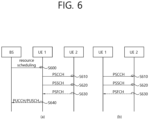
- a SCI transmitted through a PSCCH may be referred to as a 1st SCI, a first SCI, a 1st-stage SCI or a 1st-stage SCI format, and a SCI transmitted through a PSSCH may be referred to as a 2nd SCI, a second SCI, a 2nd-stage SCI or a 2nd-stage SCI format.
- the 1st-stage SCI format may include a SCI format 1-A
- the 2nd-stage SCI format may include a SCI format 2-A and/or a SCI format 2-B.
- the first UE may receive the PSFCH.
- the first UE and the second UE may determine a PSFCH resource, and the second UE may transmit HARQ feedback to the first UE using the PSFCH resource.
- the first UE may transmit SL HARQ feedback to the base station through the PUCCH and/or the PUSCH.
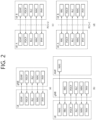
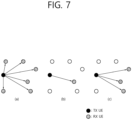
- FIG. 7 shows three cast types, in accordance with an embodiment of the present disclosure.
- the embodiment of FIG. 7 may be combined with various embodiments of the present disclosure.
- FIG. 7(a) shows broadcast-type SL communication
- FIG. 7(b) shows unicast type-SL communication
- FIG. 7(c) shows groupcast-type SL communication.
- a UE may perform one-to-one communication with respect to another UE.
- the UE may perform SL communication with respect to one or more UEs in a group to which the UE belongs.
- SL groupcast communication may be replaced with SL multicast communication, SL one-to-many communication, or the like.
- the "configure or define” wording may be interpreted as being (pre)configured (via pre-defined signaling (e.g., SIB, MAC signaling, RRC signaling)) from a base station or a network.
- pre-defined signaling e.g., SIB, MAC signaling, RRC signaling
- a may be configured may include "that a base station or network (pre-)configures/defines or informs A for a UE".
- the wording "configure or define” may be interpreted as being configured or defined in advance by a system.
- “A may be configured” may include "A is configured/defined in advance by a system”.
- FIG. 8 shows an example of an architecture in a 5G system in which positioning for a UE connected to a Next Generation-Radio Access Network (NG-RAN) or E-UTRAN is possible, according to an embodiment of the present disclosure.
- NG-RAN Next Generation-Radio Access Network
- E-UTRAN E-UTRAN
- an AMF may receive a request for a location service related to a specific target UE from a different entity such as a gateway mobile location center (GMLC), or may determine to start the location service in the AMF itself instead of the specific target UE. Then, the AMF may transmit a location service request to a location management function (LMF). Upon receiving the location service request, the LMF may process the location service request and return a processing request including an estimated position or the like of the UE to the AMF. Meanwhile, if the location service request is received from the different entity such as GMLC other than the AMF, the AMF may transfer to the different entity the processing request received from the LMF.
- GMLC gateway mobile location center
- a new generation evolved-NB (ng-eNB) and a gNB are network elements of NG-RAN capable of providing a measurement result for position estimation, and may measure a radio signal for a target UE and may transfer a resultant value to the LMF.
- the ng-eNB may control several transmission points (TPs) such as remote radio heads or PRS-dedicated TPs supporting a positioning reference signal (PRS)-based beacon system for E-UTRA.
- TPs transmission points
- PRS positioning reference signal
- the LMF may be connected to an enhanced serving mobile location centrer (E-SMLC), and the E-SMLC may allow the LMF to access E-UTRAN.
- E-SMLC may allow the LMF to support observed time difference of arrival (OTDOA), which is one of positioning methods of E-UTRAN, by using downlink measurement obtained by a target UE through a signal transmitted from the gNB and/or the PRS-dedicated TPs in the E-UTRAN.
- OTDOA observed time difference of arrival
- the LMF may be connected to an SUPL location platform (SLP).
- the LMF may support and manage different location determining services for respective target UEs.
- the LMF may interact with a serving ng-eNB or serving gNB for the target UE to obtain location measurement of the UE.
- the LMF may determine a positioning method based on a location service (LCS) client type, a requested quality of service (QoS), UE positioning capabilities, gNB positioning capabilities, and ng-eNB positioning capabilities, or the like, and may apply such a positioning method to the serving gNB and/or the serving ng-eNB.
- the LMF may determine additional information such as a position estimation value for the target UE and accuracy of position estimation and speed.
- the SLP is a secure user plane location (SUPL) entity in charge of positioning through a user plane.
- SUPL secure user plane location
- the UE may measure a downlink signal through NG-RAN, E-UTRAN, and/or other sources such as different global navigation satellite system (GNSS) and terrestrial beacon system (TBS), wireless local access network (WLAN) access points, Bluetooth beacons, UE barometric pressure sensors or the like.
- GNSS global navigation satellite system
- TBS terrestrial beacon system
- WLAN wireless local access network
- the UE may include an LCS application.
- the UE may communicate with a network to which the UE has access, or may access the LCS application through another application included in the UE.
- the LCS application may include a measurement and calculation function required to determine a position of the UE.
- the UE may include an independent positioning function such as a global positioning system (GPS), and may report the position of the UE independent of NG-RAN transmission. Positioning information obtained independently as such may be utilized as assistance information of the positioning information obtained from the network.
- GPS global positioning system
- FIG. 9 shows an implementation example of a network for measuring a position of a UE, according to an embodiment of the present disclosure.
- the embodiment of FIG. 9 may be combined with various embodiments of the present disclosure.
- CM-IDLE connection management
- the AMF may establish a signaling connection with the UE, and may request for a network trigger service to allocate a specific serving gNB or ng-eNB.
- CM connection management
- FIG. 9 Such an operational process is omitted in FIG. 9 . That is, it may be assumed in FIG. 9 that the UE is in a connected mode. However, due to signaling and data inactivation or the like, the signaling connection may be released by NG-RAN while a positioning process is performed.
- a 5GC entity such as GMLC may request a serving AMF to provide a location service for measuring a position of a target UE.
- the serving AMF may determine that the location service for measuring the position of the target UE is required. For example, to measure the position of the UE for an emergency call, the serving AMF may determine to directly perform the location service.
- the AMF may transmit the location service request to an LMF based on step S920, and the LMF may start location procedures to obtain position measurement data or position measurement assistance data together with a serving ng-eNB and a serving gNB. Additionally, based on step S935, the LMF may start location procedures for downlink positioning together with the UE. For example, the LMF may transmit assistance data defined in 3GPP TS 36.355, or may obtain a position estimation value or a position measurement value. Meanwhile, step S935 may be performed additionally after step S930 is performed, or may be performed instead of step S930.
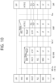
- FIG. 10 shows an example of a protocol layer used to support LTE Positioning Protocol (LPP) message transmission between an LMF and a UE, according to an embodiment of the present disclosure.
- LTP LTE Positioning Protocol
- the embodiment of FIG. 10 may be combined with various embodiments of the present disclosure.
- An LPP PDU may be transmitted through a NAS PDU between an AMF and the UE.
- an LPP may be terminated between a target device (e.g., a UE in a control plane or an SUPL enabled terminal (SET) in a user plane) and a location server (e.g., an LMF in the control plane and an SLP in the user plane).
- the LPP message may be transferred in a form of a transparent PDU through an intermediary network interface by using a proper protocol such as an NG application protocol (NGAP) through an NG-control plane (NG-C) interface and NAS/RRC or the like through an NR-Uu interface.
- the LPP protocol may enable positioning for NR and LTE by using various positioning methods.
- the target device and the location server may exchange mutual capability information, assistance data for positioning, and/or location information.
- an LPP message may be used to indicate exchange of error information and/or interruption of the LPP procedure.
- FIG. 11 shows an example of a protocol layer used to support NR Positioning Protocol A (NRPPa) PDU transmission between an LMF and an NG-RAN node, according to an embodiment of the present disclosure.
- NRPPa NR Positioning Protocol A
- the embodiment of FIG. 11 may be combined with various embodiments of the present disclosure.
- the NRPPa may be used for information exchange between the NG-RAN node and the LMF. Specifically, the NRPPa may exchange an enhanced-cell ID (E-CID) for measurement, data for supporting an OTDOA positioning method, and a cell-ID, cell location ID, or the like for an NR cell ID positioning method, transmitted from the ng-eNB to the LMF. Even if there is no information regarding an associated NRPPa transaction, the AMF may route NRPPa PDUs based on a routing ID of an associated LMR through an NG-C interface.
- E-CID enhanced-cell ID
- the AMF may route NRPPa PDUs based on a routing ID of an associated LMR through an NG-C interface.
- a procedure of an NRPPa protocol for location and data collection may be classified into two types.
- a first type is a UE associated procedure for transferring information regarding a specific UE (e.g., position measurement information or the like), and a second type is a non UE associated procedure for transferring information (e.g., , gNB/ng-eNB/TP timing information, etc.) applicable to an NG-RAN node and associated TPs.
- the two types of the procedure may be independently supported or may be simultaneously supported.
- examples of positioning methods supported in NG-RAN may include GNSS, OTDOA, enhanced cell ID (E-CID), barometric pressure sensor positioning, WLAN positioning, Bluetooth positioning and terrestrial beacon system (TBS), uplink time difference of arrival (UTDOA), etc.
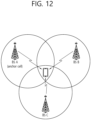
- FIG. 12 shows an Observed Time Difference Of Arrival (OTDOA) positioning method according to an embodiment of the present disclosure.
- OTDOA Observed Time Difference Of Arrival
- a UE connected to a gNB may request for a measurement gap for OTDOA measurement from the TP. If the UE cannot recognize a single frequency network (SFN) for at least one TP in the OTDOA assistance data, the UE may use an autonomous gap to obtain an SNF of an OTDOA reference cell before the measurement gap is requested to perform reference signal time difference (RSTD) measurement.
- SFN single frequency network
- RSTD reference signal time difference
- the RSTD may be defined based on a smallest relative time difference between boundaries of two subframes received respectively from a reference cell and a measurement cell. That is, the RSTD may be calculated based on a relative time difference between a start time of a subframe received from the measurement cell and a start time of a subframe of a reference cell closest to the start time of the subframe received from the measurement cell. Meanwhile, the reference cell may be selected by the UE.
- a time of arrival (TOA) of a signal received from three or more TPs or BSs geometrically distributed For example, a TOA may be measured for each of a TP1, a TP2, and a TP3, and RSTD for TP 1-TP 2, RSTD for TP 2-TP 3, and RSTD for TP 3-TP 1 may be calculated for the three TOAs. Based on this, a geometric hyperbola may be determined, and a point at which these hyperbolas intersect may be estimated as a position of a UE. In this case, since accuracy and/or uncertainty for each TOA measurement may be present, the estimated position of the UE may be known as a specific range based on measurement uncertainty.
- a position of a UE may be measured through geometric information of a serving ng-eNB, serving gNB, and/or serving cell of the UE.
- the geometric information of the serving ng-eNB, serving gNB, and/or serving cell may be obtained through paging, registration, or the like.
- an E-CID positioning method may use additional UE measurement and/or NG-RAN radio resources or the like to improve a UE position estimation value.
- additional measurement is not performed in general only for position measurement of the UE.
- a measurement configuration or a measurement control message may not be provided additionally to measure the position of the UE.
- the UE may not expect that an additional measurement operation only for position measurement will be requested, and may report a measurement value obtained through measurement methods in which the UE can perform measurement in a general manner.
- the serving gNB may use an E-UTRA measurement value provided from the UE to implement the E-CID positioning method.
- Examples of a measurement element that can be used for E-CID positioning may be as follows.
- the TADV may be classified into Type 1 and Type 2 as follows.
- TADV Type 1 ng ⁇ eNB Rx ⁇ Tx time difference + UE E ⁇ UTRA Rx ⁇ Tx time difference
- TADV Type 2 ng ⁇ eNB Rx ⁇ Tx time difference
- UTDOA is a method of determining a position of a UE by estimating an arrival time of SRS.
- the position of the UE may be estimated through an arrival time difference with respect to another cell (or BS/TP) by using a serving cell as a reference cell.
- E-SMLC may indicate a serving cell of a target UE to indicate SRS transmission to the target UE.
- the E-SMLC may provide a configuration such as whether the SRS is periodical/aperiodical, a bandwidth, frequency/group/sequence hopping, or the like.
- the reported DL PRS-RSRP value shall not be lower than the corresponding DL PRS-RSRP of any of the individual receiver branches.
- RRC_CONNECTED intra-frequency RRC_CONNECTED inter-frequency
- DL relative signal time difference DL RSTD
- DL RSTD DL relative timing difference
- T SubframeRxi is the time when the UE receives the corresponding start of one subframe from positioning node i that is closest in time to the subframe received from positioning node j .
- Multiple DL PRS resources can be used to determine the start of one subframe from a positioning node.
- the reference point for the DL RSTD shall be the antenna connector of the UE.
- the reference point for the DL RSTD shall be the antenna of the UE.
- TUL-RTOA UL Relative Time of Arrival
- T UL-RTOA shall be: - for type 1-C base station TS 38.104 [9]: the Rx antenna connector, - for type 1-O or 2-O base station TS 38.104 [9]: the Rx antenna, - for type 1-H base station TS 38.104 [9]: the Rx Transceiver Array Boundary connector.
- T gNB-TX is the positioning node transmit timing of downlink subframe #j that is closest in time to the subframe # i received from the UE. Multiple SRS resources for positioning can be used to determine the start of one subframe containing SRS.
- the reference point for T gNB-RX shall be: - for type 1-C base station TS 38.104 [9]: the Rx antenna connector, - for type 1-O or 2-O base station TS 38.104 [9]: the Rx antenna, - for type 1-H base station TS 38.104 [9]: the Rx Transceiver Array Boundary connector.
- T gNB-TX shall be: - for type 1-C base station TS 38.104 [9]: the Tx antenna connector, - for type 1-O or 2-O base station TS 38.104 [9]: the Tx antenna, - for type 1-H base station TS 38.104 [9]: the Tx Transceiver Array Boundary connector.
- UL Angle of Arrival (UL AoA) Definition
- UL Angle of Arrival (UL AoA) is defined as the estimated azimuth angle and vertical angle of a UE with respect to a reference direction, wherein the reference direction is defined: - In the global coordinate system (GCS), wherein estimated azimuth angle is measured relative to geographical North and is positive in a counter-clockwise direction and estimated vertical angle is measured relative to zenith and positive to horizontal direction - In the local coordinate system (LCS), wherein estimated azimuth angle is measured relative to x-axis of LCS and positive in a counter-clockwise direction and estimated vertical angle is measured relatize to z-axis of LCS and positive to x-y plane direction.
- GCS global coordinate system
- LCS local coordinate system
- the bearing, downtilt and slant angles of LCS are defined according to TS 38.901 [14].
- the UL AoA is determined at the gNB antenna for an UL channel corresponding to this UE.
- UL SRS-RSRP UL SRS reference signal received power
- UL SRS-RSRP is defined as linear average of the power contributions (in [W]) of the resource elements carrying sounding reference signals (SRS).
- UL SRS-RSRP shall be measured over the configured resource elements within the considered measurement frequency bandwidth in the configured measurement time occasions.
- the reference point for the UL SRS-RSRP shall be the antenna connector of the gNB.
- UL SRS-RSRP shall be measured based on the combined signal from antenna elements corresponding to a given receiver branch. For frequency range 1 and 2, if receiver diversity is in use by the gNB, the reported UL SRS-RSRP value shall not be lower than the corresponding UL SRS-RSRP of any of the individual receiver branches.
- Parameters L subCH the number of sub-channels to be used for the PSSCH transmission in a subframe, P rsvp_TX the resource reservation interval, and prio TX the priority to be transmitted in the associated SCI format 1 by the UE are all provided by higher layers (described in [8]).
- C resel is determined according to Subclause 14.1.1.4B.
- the UE In sidelink transmission mode 3, when requested by higher layers in subframe n for a carrier, the UE shall determine the set of resources to be reported to higher layers in sensing measurement according to the steps described in this Subclause.
- Parameters L subCH , P rsvp_TX and prio TX are all provided by higher layers (described in [11]).
- the UE shall determine by its implementation a set of subframes which consists of at least Y subframes within the time interval [ n + T 1 , n + T 2 ] where selections of T 1 and T 2 are up to UE implementations under T 1 ⁇ 4 and T 2min ( prio TX ) ⁇ T 2 ⁇ 100, if T 2min ( prio TX ) is provided by higher layers for prio TX , otherwise 20 ⁇ T 2 ⁇ 100 .
- UE selection of T 2 shall fulfil the latency requirement and Y shall be greater than or equal to the high layer parameter minNumCandidateSF.
- the UE shall assume that any set of L subCH contiguous sub-channels included in the corresponding PSSCH resource pool (described in 14.1.5) within the determined set of subframes correspond to one candidate single-subframe resource.
- the total number of the candidate single-subframe resources is denoted by M total .
- the UE shall monitor any subframe t y ⁇ k ⁇ P step SL if k-th bit of the high layer parameter gapCandidateSensing is set to 1.
- the UE shall perform the behaviour in the following steps based on PSCCH decoded and S-RSSI measured in these subframes.
- the UE shall exclude any candidate single-subframe resource R x,y from the set S A if it meets all the following conditions: - the UE receives an SCI format 1 in subframe t m SL , and "Resource reservation" field and "Priority” field in the received SCI format 1 indicate the values P rsvp_RX and prio RX , respectively according to Subclause 14.2.1. - PSSCH-RSRP measurement according to the received SCI format 1 is higher than Th prioTX , prio RX .
- Step 4 is repeated with Th a , b increased by 3 dB.
- the UE moves the candidate single-subframe resource R x,y with the smallest metric E x,y from the set S A to S B . This step is repeated until the number of candidate single-subframe resources in the set S B becomes greater than or equal to 0.2 ⁇ M total .
- the UE When the UE is configured by upper layers to transmit using resource pools on multiple carriers, it shall exclude a candidate single-subframe resource R x,y from S B if the UE does not support transmission in the candidate single-subframe resource in the carrier under the assumption that transmissions take place in other carrier(s) using the already selected resources due to its limitation in the number of simultaneous transmission carriers, its limitation in the supported carrier combinations, or interruption for RF retuning time [10]. [Table 15] The UE shall report set S B to higher layers.
- the UE shall assume that any set of L subCH contiguous sub-channels included in the corresponding PSSCH resource pool (described in 14.1.5) within the time interval [ n + T 1 , n + T 2 ] corresponds to one candidate single-subframe resource, where selections of T 1 and T 2 are up to UE implementations under T 1 ⁇ 4 and T 2min ( prio TX ) ⁇ T 2 ⁇ 100, if T 2min ( prio TX ) is provided by higher layers for prio TX , otherwise 20 ⁇ T 2 ⁇ 100. UE selection of T 2 shall fulfil the latency requirement.
- the total number of the candidate single-subframe resources is denoted by M total .
- the set S A is initialized to the union of all the candidate single-subframe resources.
- the set S B is initialized to an empty set.
- the UE moves the candidate single-subframe resource R x,y from the set S A to S B .
- the UE shall exclude a candidate single-subframe resource R x,y from S B if the UE does not support transmission in the candidate single-subframe resource in the carrier under the assumption that transmissions take place in other carrier(s) using the already selected resources due to its limitation in the number of simultaneous transmission carriers, its limitation in the supported carrier combinations, or interruption for RF retuning time [10].
- the UE shall report set S B to higher layers.
- the higher layer can request the UE to determine a subset of resources from which the higher layer will select resources for PSSCH/PSCCH transmission.
- the higher layer provides the following parameters for this PSSCH/PSCCH transmission: - the resource pool from which the resources are to be reported; - L1 priority, prio TX ; - the remaining packet delay budget; - the number of sub-channels to be used for the PSSCH/PSCCH transmission in a slot, L subCH ; - optionally, the resource reservation interval, P rsvp_TX , in units of msec.
- the higher layer if the higher layer requests the UE to determine a subset of resources from which the higher layer will select resources for PSSCH/PSCCH transmission as part of re-evaluation or pre-emption procedure, the higher layer provides a set of resources ( r 0 , r 1 , r 2 , ...) which may be subject to re-evaluation and a set of resources r 0 ′ , r 1 ′ , r 2 ′ , ... which may be subject to pre-emption.
- T 3 is equal to T proc , 1 SL , where T proc , 1 SL is defined in slots in Table 8.1.4-2 where ⁇ SL is the SCS configuration of the SL BWP.
- - sl-SelectionWindowList internal parameter T 2 min is set to the corresponding value from higher layer parameter sl-SelectionWindowList for the given value of prio TX .
- - sl-RS-ForSensing selects if the UE uses the PSSCH-RSRP or PSCCH-RSRP measurement, as defined in clause 8.4.2.1.
- - sl-ResourceReservePeriodList - sl-SensingWindow internal parameter T 0 is defined as the number of slots corresponding to sl-SensingWindow msec - sl-TxPercentageList : internal parameter X for a given prio TX is defined as sl-TxPercentageList ( prio TX ) converted from percentage to ratio - sl-PreemptionEnable : if sl-PreemptionEnable is provided, and if it is not equal to 'enabled', internal parameter prio pre is set to the higher layer provided parameter sl-PreemptionEnable
- the resource reservation interval, P rsvp_TX if provided, is converted from units of msec to units of logical slots, resulting
- the UE shall assume that any set of L subCH contiguous sub-channels included in the corresponding resource pool within the time interval [ n + T 1 , n + T 2 ] correspond to one candidate single-slot resource, where - selection of T 1 is up to UE implementation under 0 ⁇ T 1 ⁇ T proc , 1 SL , where T proc , 1 SL is defined in slots in Table 8.1.4-2 where ⁇ SL is the SCS configuration of the SL BWP; - if T 2 min is shorter than the remaining packet delay budget (in slots) then T 2 is up to UE implementation subject to T 2 min ⁇ T 2 ⁇ remaining packet delay budget (in slots); otherwise T 2 is set to the remaining packet delay budget (in slots).
- the total number of candidate single-slot resources is denoted by M total .
- the sensing window is defined by the range of slots n ⁇ T 0 , n ⁇ T proc , 0 SL where T 0 is defined above and T proc , 0 SL is defined in slots in Table 8.1.4-1 where ⁇ SL is the SCS configuration of the SL BWP.
- the UE shall monitor slots which belongs to a sidelink resource pool within the sensing window except for those in which its own transmissions occur. The UE shall perform the behaviour in the following steps based on PSCCH decoded and RSRP measured in these slots.
- the set S A is initialized to the set of all the candidate single-slot resources.
- the UE shall exclude any candidate single-slot resource R x,y from the set S A if it meets all the following conditions: - the UE has not monitored slot t ′ m SL in Step 2.
- condition c in step 6 would be met. 5a) If the number of candidate single-slot resources R x,y remaining in the set S A is smaller than X ⁇ M total , the set S A is initialized to the set of all the candidate single-slot resources as in step 4.
- a resource r i ′ from the set r 0 ′ , r 1 ′ , r 2 ′ , ... meets the conditions below then the UE shall report pre-emption of the resource r i ′ to higher layers - r i ′ is not a member of S A , and - r i ′ meets the conditions for exclusion in step 6, with Th ( prio RX , prio TX ) set to the final threshold after executing steps 1)-7), i.e.
- LCH or service priority and/or QOS requirements (e.g., latency, reliability, minimum communication range) and/or PQI parameters)
- QOS requirements e.g., latency, reliability, minimum communication range
- PQI parameters e.g., HARQ feedback enabled (and/or disabled) LCH/MAC PDU (transmission) and/or CBR measurement value of a resource pool and/or SL cast type (e.g., unicast, groupcast, broadcast) and/or SL groupcast HARQ feedback option (e.g., NACK only feedback, ACK/NACK feedback, NACK only feedback based on TX-RX distance) and/or SL mode 1 CG type (e.g., SL CG type 1/2) and/or SL mode type (e.g., mode 1/2) and/or resource pool and/or PSFCH resource configured resource pool and/or source (L2) ID (and/or destination (L2) ID) and/or PC5 RRC connection/link and/or SL link and
- an SL PRS configuration may include the following information.
- a control channel used for SL PRS transmission may include the following contents.
- the reserved resource indication value may indicate information regarding N SL PRS resources
- a corresponding field in an SPCCH may indicate a (RE) resource (the fastest resource in the time and/or frequency domain) with the smallest index in the time and/or frequency domain among resources belonging to each SL PRS resource.
- the location of an SL PRS resource transmitted by a UE transmitting the SPCCH may be estimated.
- the reserved resource indication field may indicate the location of a representative resource representing an SL PRS resource instead of a (RE) resource with the minimum index.
- the reserved resource indication field may indicate only resources within an MG through which a corresponding SPCCH is transmitted. If an SL PRS resource transmitted in an (MG) region other than the MG in which the corresponding SPCCH is transmitted is indicated, a SPCCH may also signal an MG index to which the SL PRS resource belongs.
- the reserved resource indication field in an SPCCH transmitted in an MG may signal only information regarding the location of an SL PRS resource belonging to the MG. That is, information regarding the location of an SL PRS resource belonging to an area other than the MG cannot be signaled.
- a UE may measure the RSRP of a reference signal (RS) used in an SPCCH including the SL PRS information.
- RS reference signal
- a UE may measure received signal strength indication (RSSI) or RSRP or the correlation between a defined SL PRS resource pattern and a received SL PRS resource pattern for each SL PRS resource pattern, based on an SL PRS configuration configured in the corresponding SL resource pool or MG, for the SL PRS resource patterns (e.g., comb size, RE offset, number of symbols) allowed to be transmitted to the resource pool and/or MG, For example, as described above, a UE may measure RSSI, RSRP, or the correlation based on the SL PRS resource pattern it intends to transmit.
- RSSI received signal strength indication
- RSRP received signal strength indication
- a UE may expect/determine that an SPCCH is transmitted through a separate channel or that an SL PRS is transmitted by reusing an SL PRS resource of the detected position within the next MG or SL PRS resource set.
- resources for which the above-described SPCCH RSRP is greater than or equal to a specific threshold and that satisfy the following conditions may be excluded from resources for transmitting SL PRS resources.
- SL PRS resources of specific threshold value N corresponding to the same location after the corresponding resource may be excluded from resources for transmitting SL PRS resources.
- SL PRS resources reserved by SPCCH or SL PRS resources of periodic transmission positions indicated by an SPCCH may be excluded from resources for SL PRS transmission to be transmitted by a UE.
- an SPCCH resource reserved by an SPCCH or an SL PRS resource of a periodic transmission location indicated by an SPCCH may be selected as a resource for SL PRS resource transmission.
- a first UE may determine at least one SL PRS candidate resource for transmitting an SL PRS.
- the first UE may receive a PRS-related control channel transmitted by a second UE from the second UE.
- the control channel may include information related to at least one resource that the second UE will use to transmit an SL PRS.
- the first UE may update the at least one SL PRS candidate resource, based on information related to at least one resource included in the control channel and to be used by the second UE.
- the updating may include an operation of excluding at least one resource to be used by the second UE to transmit an SL PRS from the at least one SL PRS candidate resource.
- the excluded resource may be a resource overlapping with the at least one SL PRS candidate resource.
- the first UE may select at least one SL PRS resource to be used for transmitting its own SL PRS among the updated at least one SL PRS candidate resource. And, in step S1350, the first UE may transmit its own SL PRS to a third UE based on the at least one SL PRS resource to be used for transmitting its own SL PRS. For example, positioning for the first UE may be performed based on the SL PRS.
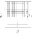
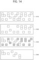
- FIG. 14 shows an embodiment in which SL PRS candidate resources are updated according to an embodiment of the present disclosure.
- the embodiment of FIG. 14 may be combined with various embodiments of the present disclosure.
- 1410 may represent SL PRS candidate resources selected by a first UE (a UE intending to transmit an SL PRS).
- the first UE may receive information 1420 related to SL PRS resources related to an SL PRS to be transmitted by a second UE from the second UE.
- constraints in the time domain to be applied in selecting transmission resources for SL PRS transmission need to be defined.
- a method for minimum and maximum time conditions between SL PRS transmission resources to be applied in selecting transmission resources for SL PRS transmission and a device supporting the same are proposed.
- SL PRS transmission resources may be composed of a set of SL PRS resources consisting of the following information.
- the SL PRS resource set may be composed of SL PRS resources composed of the following information.
- the first control information may include information related to a resource with a lowest index among the at least one first SL PRS resource.
- the first control information may include an SL PRS resource set ID related to the at least one first SL PRS resource.
- first control information related to PRS may be received to the first device through a first control channel related to PRS
- a third SL PRS resource may be excluded from at least one first SL PRS candidate resource, based on an RSRP value of the first control channel being greater than or equal to a first threshold and a number of the at least one third SL PRS resource, in which the at least one first SL PRS candidate resource and at least one second SL PRS resource overlap, being greater than or equal to a second threshold
- information related to the at least one second SL PRS resource may be obtained by the first device based on the first control information
- the at least one first SL PRS resource may be selected among the at least one first SL PRS candidate resource
- positioning for the first device may be performed based on the first PRS and the second PRS.
- the at least one first SL PRS resource may be selected among the at least one first SL PRS candidate resource, in which the at least one third PRS resource is excluded.
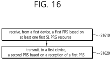
- a processor 202 of a second device 200 may control a transceiver 206 to receive, from a first device 100, a first positioning reference signal, PRS, based on at least one first sidelink, SL, PRS resource. And, the processor 202 of the second device 200 may control the transceiver 206 transmit, to the first device 100, a second PRS based on the reception of the first PRS.
- the at least one first SL PRS resource may be selected among the at least one first SL PRS candidate resource, in which the at least one third PRS resource is excluded.
- various configuration information configuring processes various signal processing processes (e.g., channel encoding/decoding, modulation/demodulation, and resource mapping/demapping), and resource allocating processes, for transmitting/receiving radio signals, may be performed based on the various proposals of the present disclosure.
- various signal processing processes e.g., channel encoding/decoding, modulation/demodulation, and resource mapping/demapping
- resource allocating processes for transmitting/receiving radio signals
- the one or more processors 102 and 202 may receive the signals (e.g., baseband signals) from the one or more transceivers 106 and 206 and acquire the PDUs, SDUs, messages, control information, data, or information according to the descriptions, functions, procedures, proposals, methods, and/or operational flowcharts disclosed in this document.
- signals e.g., baseband signals
- the one or more processors 102 and 202 may be referred to as controllers, microcontrollers, microprocessors, or microcomputers.
- the one or more processors 102 and 202 may be implemented by hardware, firmware, software, or a combination thereof.
- ASICs Application Specific Integrated Circuits
- DSPs Digital Signal Processors
- DSPDs Digital Signal Processing Devices
- PLDs Programmable Logic Devices
- FPGAs Field Programmable Gate Arrays
- the descriptions, functions, procedures, proposals, methods, and/or operational flowcharts disclosed in this document may be implemented using firmware or software and the firmware or software may be configured to include the modules, procedures, or functions.
- Firmware or software configured to perform the descriptions, functions, procedures, proposals, methods, and/or operational flowcharts disclosed in this document may be included in the one or more processors 102 and 202 or stored in the one or more memories 104 and 204 so as to be driven by the one or more processors 102 and 202.
- the descriptions, functions, procedures, proposals, methods, and/or operational flowcharts disclosed in this document may be implemented using firmware or software in the form of code, commands, and/or a set of commands.
- the one or more memories 104 and 204 may be connected to the one or more processors 102 and 202 and store various types of data, signals, messages, information, programs, code, instructions, and/or commands.
- the one or more memories 104 and 204 may be configured by Read-Only Memories (ROMs), Random Access Memories (RAMs), Electrically Erasable Programmable Read-Only Memories (EPROMs), flash memories, hard drives, registers, cash memories, computer-readable storage media, and/or combinations thereof.
- the one or more memories 104 and 204 may be located at the interior and/or exterior of the one or more processors 102 and 202.
- the one or more memories 104 and 204 may be connected to the one or more processors 102 and 202 through various technologies such as wired or wireless connection.
- the one or more transceivers 106 and 206 may transmit user data, control information, and/or radio signals/channels, mentioned in the methods and/or operational flowcharts of this document, to one or more other devices.
- the one or more transceivers 106 and 206 may receive user data, control information, and/or radio signals/channels, mentioned in the descriptions, functions, procedures, proposals, methods, and/or operational flowcharts disclosed in this document, from one or more other devices.
- the one or more transceivers 106 and 206 may be connected to the one or more processors 102 and 202 and transmit and receive radio signals.
- the one or more processors 102 and 202 may perform control so that the one or more transceivers 106 and 206 may transmit user data, control information, or radio signals to one or more other devices.
- the one or more processors 102 and 202 may perform control so that the one or more transceivers 106 and 206 may receive user data, control information, or radio signals from one or more other devices.
- the one or more transceivers 106 and 206 may be connected to the one or more antennas 108 and 208 and the one or more transceivers 106 and 206 may be configured to transmit and receive user data, control information, and/or radio signals/channels, mentioned in the descriptions, functions, procedures, proposals, methods, and/or operational flowcharts disclosed in this document, through the one or more antennas 108 and 208.
- the one or more antennas may be a plurality of physical antennas or a plurality of logical antennas (e.g., antenna ports).
- the one or more transceivers 106 and 206 may convert received radio signals/channels etc.
- the one or more transceivers 106 and 206 may convert the user data, control information, radio signals/channels, etc. processed using the one or more processors 102 and 202 from the base band signals into the RF band signals.
- the one or more transceivers 106 and 206 may include (analog) oscillators and/or filters.
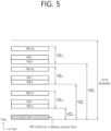
- FIG. 19 shows a signal process circuit for a transmission signal, based on an embodiment of the present disclosure.
- the embodiment of FIG. 19 may be combined with various embodiments of the present disclosure.
- a signal processing circuit 1000 may include scramblers 1010, modulators 1020, a layer mapper 1030, a precoder 1040, resource mappers 1050, and signal generators 1060.
- An operation/function of FIG. 19 may be performed, without being limited to, the processors 102 and 202 and/or the transceivers 106 and 206 of FIG. 18 .
- Hardware elements of FIG. 19 may be implemented by the processors 102 and 202 and/or the transceivers 106 and 206 of FIG. 18 .
- blocks 1010 to 1060 may be implemented by the processors 102 and 202 of FIG. 18 .
- the blocks 1010 to 1050 may be implemented by the processors 102 and 202 of FIG. 18 and the block 1060 may be implemented by the transceivers 106 and 206 of FIG. 18 .
- Codewords may be converted into radio signals via the signal processing circuit 1000 of FIG. 19 .
- the codewords are encoded bit sequences of information blocks.
- the information blocks may include transport blocks (e.g., a UL-SCH transport block, a DL-SCH transport block).
- the radio signals may be transmitted through various physical channels (e.g., a PUSCH and a PDSCH).
- the codewords may be converted into scrambled bit sequences by the scramblers 1010.
- Scramble sequences used for scrambling may be generated based on an initialization value, and the initialization value may include ID information of a wireless device.
- the scrambled bit sequences may be modulated to modulation symbol sequences by the modulators 1020.
- a modulation scheme may include pi/2-Binary Phase Shift Keying (pi/2-BPSK), m-Phase Shift Keying (m-PSK), and m-Quadrature Amplitude Modulation (m-QAM).
- Complex modulation symbol sequences may be mapped to one or more transport layers by the layer mapper 1030.
- Modulation symbols of each transport layer may be mapped (precoded) to corresponding antenna port(s) by the precoder 1040.
- Outputs z of the precoder 1040 may be obtained by multiplying outputs y of the layer mapper 1030 by an N*M precoding matrix W.
- N is the number of antenna ports and M is the number of transport layers.
- the precoder 1040 may perform precoding after performing transform precoding (e.g., DFT) for complex modulation symbols. Alternatively, the precoder 1040 may perform precoding without performing transform precoding.
- transform precoding e.g., DFT
- the resource mappers 1050 may map modulation symbols of each antenna port to time-frequency resources.
- the time-frequency resources may include a plurality of symbols (e.g., a CP-OFDMA symbols and DFT-s-OFDMA symbols) in the time domain and a plurality of subcarriers in the frequency domain.
- the signal generators 1060 may generate radio signals from the mapped modulation symbols and the generated radio signals may be transmitted to other devices through each antenna.
- the signal generators 1060 may include Inverse Fast Fourier Transform (IFFT) modules, Cyclic Prefix (CP) inserters, Digital-to-Analog Converters (DACs), and frequency up-converters.
- IFFT Inverse Fast Fourier Transform
- CP Cyclic Prefix
- DACs Digital-to-Analog Converters
- Signal processing procedures for a signal received in the wireless device may be configured in a reverse manner of the signal processing procedures 1010 to 1060 of FIG. 19 .
- the wireless devices e.g., 100 and 200 of FIG. 18
- the received radio signals may be converted into baseband signals through signal restorers.
- the signal restorers may include frequency downlink converters, Analog-to-Digital Converters (ADCs), CP remover, and Fast Fourier Transform (FFT) modules.
- ADCs Analog-to-Digital Converters
- FFT Fast Fourier Transform
- the baseband signals may be restored to codewords through a resource demapping procedure, a postcoding procedure, a demodulation processor, and a descrambling procedure.
- a signal processing circuit for a reception signal may include signal restorers, resource demappers, a postcoder, demodulators, descramblers, and decoders.
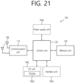
- FIG. 20 shows another example of a wireless device, based on an embodiment of the present disclosure.
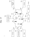
- the wireless device may be implemented in various forms according to a use-case/service (refer to FIG. 17 ).
- the embodiment of FIG. 20 may be combined with various embodiments of the present disclosure.
- the control unit 120 is electrically connected to the communication unit 110, the memory 130, and the additional components 140 and controls overall operation of the wireless devices. For example, the control unit 120 may control an electric/mechanical operation of the wireless device based on programs/code/commands/information stored in the memory unit 130.
- the control unit 120 may transmit the information stored in the memory unit 130 to the exterior (e.g., other communication devices) via the communication unit 110 through a wireless/wired interface or store, in the memory unit 130, information received through the wireless/wired interface from the exterior (e.g., other communication devices) via the communication unit 110.
- the wireless device may be used in a mobile or fixed place according to a use-example/service.
Landscapes
- Engineering & Computer Science (AREA)
- Signal Processing (AREA)
- Computer Networks & Wireless Communication (AREA)
- Quality & Reliability (AREA)
- Physics & Mathematics (AREA)
- Electromagnetism (AREA)
- Mobile Radio Communication Systems (AREA)
Claims (14)
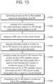
- Verfahren zum Durchführen einer drahtlosen Kommunikation durch eine erste Vorrichtung, wobei das Verfahren Folgendes umfasst:Bestimmen (S1510) mindestens einer ersten SL-Positionsbestimmungsreferenzsignal-, PRS-, Kandidatenressource zum Übertragen eines ersten SL-PRS;Empfangen (S1520), von einer zweiten Vorrichtung, einer ersten Steuerinformation in Bezug auf ein SL-PRS durch einen ersten Steuerkanal in Bezug auf das SL-PRS;Erhalten (S1530) eines Referenzsignalempfangsleistungs-, RSRP, Werts des ersten Steuerkanals;Erhalten (S1540) einer Information in Bezug auf mindestens eine erste durch die zweite Vorrichtung zu verwendende SL-PRS-Ressource basierend auf der ersten Steuerinformation;Ausschließen (S1550) mindestens einer zweiten SL-PRS-Ressource aus der mindestens einen ersten SL-PRS-Kandidatenressource basierend darauf, dass i) der RSRP-Wert des ersten Steuerkanals größer oder gleich einem ersten Schwellenwert ist und ii) eine Anzahl der mindestens einen zweiten SL-PRS-Ressource größer oder gleich einem zweiten Schwellenwert ist,wobei die mindestens eine zweite SL-PRS-Ressource mindestens eine Ressource ist, die sich zwischen der mindestens einen ersten SL-PRS-Kandidatenressource und der mindestens einen ersten SL-PRS-Ressource überlappt; undÜbertragen (S1560) des ersten SL-PRS basierend auf der mindestens einen ersten SL-PRS-Kandidatenressource, wobei die mindestens eine zweite SL-PRS-Ressource ausgeschlossen wird.
- Verfahren nach Anspruch 1, das ferner Folgendes umfasst:Erhalten einer Information in Bezug auf eine Messlückenperiode, in der mehrere Sidelink-, SL-, Positionsbestimmungsreferenzsignal-, PRS-,Konfigurationen konfiguriert sind,wobei eine Übertragung von SL-Daten in der Messlückenperiode nicht zulässig ist.
- Verfahren nach Anspruch 1, das ferner Folgendes umfasst:
Durchführen einer Positionsbestimmung für die erste Vorrichtung basierend auf dem ersten SL-PRS. - Verfahren nach Anspruch 1, wobei basierend darauf, dass der RSRP-Wert größer oder gleich dem ersten Schwellenwert ist und die Anzahl der mindestens einen zweiten SL-PRS-Ressource kleiner oder gleich dem zweiten Schwellenwert ist, die mindestens eine zweite SL-PRS-Ressource nicht aus der mindestens einen ersten SL-PRS-Kandidatenressource ausgeschlossen wird.
- Verfahren nach Anspruch 1, wobei die mindestens eine erste SL-PRS-Kandidatenressource und die mindestens eine zweite SL-PRS-Ressource Musterformen sind.
- Verfahren nach Anspruch 1, wobei die mindestens eine erste SL-PRS-Kandidatenressource basierend auf einer ersten SL-PRS-Konfiguration bestimmt wird, und
wobei die mindestens eine zweite SL-PRS-Ressource basierend auf einer zweiten SL-PRS-Konfiguration bestimmt wird. - Verfahren nach Anspruch 1, wobei die erste Steuerinformation eine Information in Bezug auf einen Messlückenindex umfasst.
- Verfahren nach Anspruch 1, wobei die erste Steuerinformation eine Information in Bezug auf die mindestens eine erste SL-PRS-Ressource umfasst.
- Verfahren nach Anspruch 8, wobei die erste Steuerinformation eine Information in Bezug auf eine Ressource mit einem niedrigsten Index unter der mindestens einen ersten SL-PRS-Ressource umfasst.
- Verfahren nach Anspruch 8, wobei die erste Steuerinformation eine Information in Bezug auf einen Standort einer repräsentativen Ressource der mindestens einen ersten SL-PRS-Ressource umfasst.
- Verfahren nach Anspruch 8, wobei die erste Steuerinformation eine SL-PRS-Ressourcen-ID in Bezug auf die mindestens eine erste SL-PRS-Ressource umfasst.
- Verfahren nach Anspruch 8, wobei die erste Steuerinformation eine SL-PRS-Ressourcensatz-ID in Bezug auf die mindestens eine erste SL-PRS-Ressource umfasst.
- Erste Vorrichtung zum Durchführen einer drahtlosen Kommunikation, wobei die erste Vorrichtung Folgendes umfasst:einen oder mehrere Speicher, die Anweisungen speichern; undeinen oder mehrere Prozessoren, die mit dem einen oder den mehreren Speichern verbunden sind, wobei der eine oder die mehreren Prozessoren die Anweisungen zu Folgendem ausführen:Bestimmen (S1510) mindestens einer ersten SL-Positionsbestimmungsreferenzsignal-, PRS-, Kandidatenressource zum Übertragen eines ersten SL-PRS;Empfangen (S1520), von einer zweiten Vorrichtung, einer ersten Steuerinformation in Bezug auf ein SL-PRS durch einen ersten Steuerkanal in Bezug auf das SL-PRS;Erhalten (S1530) eines Referenzsignalempfangsleistungs-, RSRP, Werts des ersten Steuerkanals;Erhalten (S1540) einer Information in Bezug auf mindestens eine erste durch die zweite Vorrichtung zu verwendende SL-PRS-Ressource basierend auf der ersten Steuerinformation;Ausschließen (S1550) mindestens einer zweiten SL-PRS-Ressource aus der mindestens einen ersten SL-PRS-Kandidatenressource basierend darauf, dass i) der RSRP-Wert des ersten Steuerkanals größer oder gleich einem ersten Schwellenwert ist und ii) eine Anzahl der mindestens einen zweiten SL-PRS-Ressource größer oder gleich einem zweiten Schwellenwert ist,wobei die mindestens eine zweite SL-PRS-Ressource mindestens eine Ressource ist, die sich zwischen der mindestens einen ersten SL-PRS-Kandidatenressource und der mindestens einen ersten SL-PRS-Ressource überlappt; undÜbertragen (S1560) des ersten SL-PRS basierend auf der mindestens einen ersten SL-PRS-Kandidatenressource, wobei die mindestens eine zweite SL-PRS-Ressource ausgeschlossen wird.
- Erste Vorrichtung nach Anspruch 13, wobei die erste Vorrichtung ferner einen oder mehrere Sendeempfänger umfasst, die durch den einen oder die mehreren Prozessoren gesteuert werden, um den Übertragungsvorgang und den Empfangsvorgang durchzuführen.
Applications Claiming Priority (2)
| Application Number | Priority Date | Filing Date | Title |
|---|---|---|---|
| US202263315471P | 2022-03-01 | 2022-03-01 | |
| US202263333619P | 2022-04-22 | 2022-04-22 |
Publications (2)
| Publication Number | Publication Date |
|---|---|
| EP4239930A1 EP4239930A1 (de) | 2023-09-06 |
| EP4239930B1 true EP4239930B1 (de) | 2025-07-09 |
Family
ID=85175992
Family Applications (1)
| Application Number | Title | Priority Date | Filing Date |
|---|---|---|---|
| EP23155069.0A Active EP4239930B1 (de) | 2022-03-01 | 2023-02-06 | Verfahren und vorrichtung zur erfassung für sl-prs-ressourcenauswahl |
Country Status (3)
| Country | Link |
|---|---|
| US (1) | US12402098B2 (de) |
| EP (1) | EP4239930B1 (de) |
| KR (1) | KR102871519B1 (de) |
Families Citing this family (4)
| Publication number | Priority date | Publication date | Assignee | Title |
|---|---|---|---|---|
| WO2025055001A1 (zh) * | 2023-09-15 | 2025-03-20 | 北京小米移动软件有限公司 | 资源确定方法、终端、通信系统及存储介质 |
| WO2025065581A1 (en) * | 2023-09-28 | 2025-04-03 | Zte Corporation | Rs transmission opportunities and grants in wireless communications |
| KR20250176574A (ko) | 2023-10-25 | 2025-12-19 | 켁텔 와이어리스 솔루션즈 코퍼레이션 리미티드 | 무선 통신을 위한 노드에서의 방법 및 장치 |
| CN119946851A (zh) * | 2023-11-03 | 2025-05-06 | 华为技术有限公司 | 调度sl-prs传输的方法及相关装置 |
Family Cites Families (4)
| Publication number | Priority date | Publication date | Assignee | Title |
|---|---|---|---|---|
| KR102367084B1 (ko) * | 2017-08-01 | 2022-02-24 | 삼성전자 주식회사 | 사용자 장치를 위한 위치 결정 방법 및 디바이스와 사용자 장치 |
| EP3858027B1 (de) * | 2018-09-28 | 2023-09-13 | Telefonaktiebolaget LM Ericsson (publ) | Anpassung von operationen in flexiblen zuweisungsslots, die teilweise mit messlücken überlappen |
| KR20220020815A (ko) * | 2019-06-13 | 2022-02-21 | 엘지전자 주식회사 | Nr v2x에서 서버 단말의 prs 전송에 기반한 사이드링크 포지셔닝 |
| US12442883B2 (en) * | 2019-11-01 | 2025-10-14 | Lg Electronics Inc. | Method for performing relative positioning by terminal in wireless communication system supporting sidelink, and apparatus therefor |
-
2022
- 2022-09-13 KR KR1020220115204A patent/KR102871519B1/ko active Active
-
2023
- 2023-02-06 EP EP23155069.0A patent/EP4239930B1/de active Active
- 2023-02-16 US US18/110,839 patent/US12402098B2/en active Active
Also Published As
| Publication number | Publication date |
|---|---|
| KR102871519B1 (ko) | 2025-10-15 |
| KR20230129286A (ko) | 2023-09-08 |
| EP4239930A1 (de) | 2023-09-06 |
| US20230284173A1 (en) | 2023-09-07 |
| US12402098B2 (en) | 2025-08-26 |
Similar Documents
| Publication | Publication Date | Title |
|---|---|---|
| US12538254B2 (en) | Network configuration-based sidelink positioning method and apparatus | |
| US12250168B2 (en) | Method and device for transmitting S-PRS in NR V2X | |
| US12282086B2 (en) | Method and apparatus for efficient assistance data transfer in NR positioning | |
| EP4239930B1 (de) | Verfahren und vorrichtung zur erfassung für sl-prs-ressourcenauswahl | |
| EP4236158B1 (de) | Verfahren und vorrichtung zur messspaltbildung zur sl-positionierung | |
| EP4246852A1 (de) | Verfahren und vorrichtung zur slprs-übertragung zur sl-positionierung | |
| US20250063532A1 (en) | Method and device for sensing-based sl prs transmission resource selection for sl positioning | |
| US12323358B2 (en) | Method and device for SL PRS transmission based on measurement gap | |
| US12501451B2 (en) | Method and apparatus for performing positioning based on congestion control in NR V2X | |
| EP4514034A1 (de) | Verfahren und vorrichtung zur durchführung von drahtloser kommunikation im zusammenhang mit slprs | |
| EP4568157A1 (de) | Slprs-konfigurationsverfahren und -vorrichtung | |
| EP4514039A1 (de) | Verfahren und vorrichtung zum senden oder empfangen von slprs | |
| EP4518528A1 (de) | Verfahren und vorrichtung zur ressourcenauswahl für slprs-übertragung | |
| EP4489485A1 (de) | Verfahren und vorrichtung zur durchführung eines verfahrens auf höherer schicht zur sl-positionierung | |
| EP4266078B1 (de) | Verfahren und vorrichtung zur synchronisation für sl-positionierung | |
| EP4240073A1 (de) | Verfahren und vorrichtung zur bildung einer positionierungsgruppe in nr v2x | |
| US20230344595A1 (en) | Method and apparatus for performing wireless communication related to sl prs in nr v2x | |
| EP4564946A1 (de) | Verfahren und vorrichtung zur durchführung einer positionierung auf der basis von sldrx | |
| EP4608027A1 (de) | Verfahren und vorrichtung zur durchführung einer positionierung auf basis eines ressourcenpools | |
| EP4629716A1 (de) | Verfahren und vorrichtung zur cbr-messung für slprs | |
| US20250365693A1 (en) | Method and device for determining resource pool for sl prs transmission and reception |
Legal Events
| Date | Code | Title | Description |
|---|---|---|---|
| PUAI | Public reference made under article 153(3) epc to a published international application that has entered the european phase |
Free format text: ORIGINAL CODE: 0009012 |
|
| STAA | Information on the status of an ep patent application or granted ep patent |
Free format text: STATUS: REQUEST FOR EXAMINATION WAS MADE |
|
| 17P | Request for examination filed |
Effective date: 20230206 |
|
| AK | Designated contracting states |
Kind code of ref document: A1 Designated state(s): AL AT BE BG CH CY CZ DE DK EE ES FI FR GB GR HR HU IE IS IT LI LT LU LV MC ME MK MT NL NO PL PT RO RS SE SI SK SM TR |
|
| GRAP | Despatch of communication of intention to grant a patent |
Free format text: ORIGINAL CODE: EPIDOSNIGR1 |
|
| STAA | Information on the status of an ep patent application or granted ep patent |
Free format text: STATUS: GRANT OF PATENT IS INTENDED |
|
| RIC1 | Information provided on ipc code assigned before grant |
Ipc: H04L 5/00 20060101AFI20250211BHEP |
|
| INTG | Intention to grant announced |
Effective date: 20250227 |
|
| GRAS | Grant fee paid |
Free format text: ORIGINAL CODE: EPIDOSNIGR3 |
|
| GRAA | (expected) grant |
Free format text: ORIGINAL CODE: 0009210 |
|
| STAA | Information on the status of an ep patent application or granted ep patent |
Free format text: STATUS: THE PATENT HAS BEEN GRANTED |
|
| AK | Designated contracting states |
Kind code of ref document: B1 Designated state(s): AL AT BE BG CH CY CZ DE DK EE ES FI FR GB GR HR HU IE IS IT LI LT LU LV MC ME MK MT NL NO PL PT RO RS SE SI SK SM TR |
|
| REG | Reference to a national code |
Ref country code: GB Ref legal event code: FG4D |
|
| REG | Reference to a national code |
Ref country code: CH Ref legal event code: EP |
|
| REG | Reference to a national code |
Ref country code: IE Ref legal event code: FG4D |
|
| REG | Reference to a national code |
Ref country code: DE Ref legal event code: R096 Ref document number: 602023004589 Country of ref document: DE |
|
| REG | Reference to a national code |
Ref country code: NL Ref legal event code: MP Effective date: 20250709 |
|
| PG25 | Lapsed in a contracting state [announced via postgrant information from national office to epo] |
Ref country code: PT Free format text: LAPSE BECAUSE OF FAILURE TO SUBMIT A TRANSLATION OF THE DESCRIPTION OR TO PAY THE FEE WITHIN THE PRESCRIBED TIME-LIMIT Effective date: 20251110 |
|
| PG25 | Lapsed in a contracting state [announced via postgrant information from national office to epo] |
Ref country code: NL Free format text: LAPSE BECAUSE OF FAILURE TO SUBMIT A TRANSLATION OF THE DESCRIPTION OR TO PAY THE FEE WITHIN THE PRESCRIBED TIME-LIMIT Effective date: 20250709 |
|
| REG | Reference to a national code |
Ref country code: AT Ref legal event code: MK05 Ref document number: 1812893 Country of ref document: AT Kind code of ref document: T Effective date: 20250709 |
|
| PG25 | Lapsed in a contracting state [announced via postgrant information from national office to epo] |
Ref country code: IS Free format text: LAPSE BECAUSE OF FAILURE TO SUBMIT A TRANSLATION OF THE DESCRIPTION OR TO PAY THE FEE WITHIN THE PRESCRIBED TIME-LIMIT Effective date: 20251109 |
|
| PG25 | Lapsed in a contracting state [announced via postgrant information from national office to epo] |
Ref country code: NO Free format text: LAPSE BECAUSE OF FAILURE TO SUBMIT A TRANSLATION OF THE DESCRIPTION OR TO PAY THE FEE WITHIN THE PRESCRIBED TIME-LIMIT Effective date: 20251009 |
|
| REG | Reference to a national code |
Ref country code: LT Ref legal event code: MG9D |
|
| PG25 | Lapsed in a contracting state [announced via postgrant information from national office to epo] |
Ref country code: AT Free format text: LAPSE BECAUSE OF FAILURE TO SUBMIT A TRANSLATION OF THE DESCRIPTION OR TO PAY THE FEE WITHIN THE PRESCRIBED TIME-LIMIT Effective date: 20250709 |
|
| PG25 | Lapsed in a contracting state [announced via postgrant information from national office to epo] |
Ref country code: FI Free format text: LAPSE BECAUSE OF FAILURE TO SUBMIT A TRANSLATION OF THE DESCRIPTION OR TO PAY THE FEE WITHIN THE PRESCRIBED TIME-LIMIT Effective date: 20250709 |
|
| PG25 | Lapsed in a contracting state [announced via postgrant information from national office to epo] |
Ref country code: HR Free format text: LAPSE BECAUSE OF FAILURE TO SUBMIT A TRANSLATION OF THE DESCRIPTION OR TO PAY THE FEE WITHIN THE PRESCRIBED TIME-LIMIT Effective date: 20250709 |
|
| PG25 | Lapsed in a contracting state [announced via postgrant information from national office to epo] |
Ref country code: GR Free format text: LAPSE BECAUSE OF FAILURE TO SUBMIT A TRANSLATION OF THE DESCRIPTION OR TO PAY THE FEE WITHIN THE PRESCRIBED TIME-LIMIT Effective date: 20251010 |
|
| PG25 | Lapsed in a contracting state [announced via postgrant information from national office to epo] |
Ref country code: SE Free format text: LAPSE BECAUSE OF FAILURE TO SUBMIT A TRANSLATION OF THE DESCRIPTION OR TO PAY THE FEE WITHIN THE PRESCRIBED TIME-LIMIT Effective date: 20250709 |
|
| PG25 | Lapsed in a contracting state [announced via postgrant information from national office to epo] |
Ref country code: LV Free format text: LAPSE BECAUSE OF FAILURE TO SUBMIT A TRANSLATION OF THE DESCRIPTION OR TO PAY THE FEE WITHIN THE PRESCRIBED TIME-LIMIT Effective date: 20250709 |
|
| PG25 | Lapsed in a contracting state [announced via postgrant information from national office to epo] |
Ref country code: BG Free format text: LAPSE BECAUSE OF FAILURE TO SUBMIT A TRANSLATION OF THE DESCRIPTION OR TO PAY THE FEE WITHIN THE PRESCRIBED TIME-LIMIT Effective date: 20250709 Ref country code: PL Free format text: LAPSE BECAUSE OF FAILURE TO SUBMIT A TRANSLATION OF THE DESCRIPTION OR TO PAY THE FEE WITHIN THE PRESCRIBED TIME-LIMIT Effective date: 20250709 |
|
| PG25 | Lapsed in a contracting state [announced via postgrant information from national office to epo] |
Ref country code: RS Free format text: LAPSE BECAUSE OF FAILURE TO SUBMIT A TRANSLATION OF THE DESCRIPTION OR TO PAY THE FEE WITHIN THE PRESCRIBED TIME-LIMIT Effective date: 20251009 |
|
| PG25 | Lapsed in a contracting state [announced via postgrant information from national office to epo] |
Ref country code: ES Free format text: LAPSE BECAUSE OF FAILURE TO SUBMIT A TRANSLATION OF THE DESCRIPTION OR TO PAY THE FEE WITHIN THE PRESCRIBED TIME-LIMIT Effective date: 20250709 |