EP4239821A1 - Dc household appliance with a switching circuit - Google Patents
Dc household appliance with a switching circuit Download PDFInfo
- Publication number
- EP4239821A1 EP4239821A1 EP22159321.3A EP22159321A EP4239821A1 EP 4239821 A1 EP4239821 A1 EP 4239821A1 EP 22159321 A EP22159321 A EP 22159321A EP 4239821 A1 EP4239821 A1 EP 4239821A1
- Authority
- EP
- European Patent Office
- Prior art keywords
- household appliance
- supply line
- supply
- switching circuit
- switching element
- Prior art date
- Legal status (The legal status is an assumption and is not a legal conclusion. Google has not performed a legal analysis and makes no representation as to the accuracy of the status listed.)
- Pending
Links
- 239000004065 semiconductor Substances 0.000 claims abstract description 27
- 238000006243 chemical reaction Methods 0.000 claims abstract description 6
- 238000005406 washing Methods 0.000 claims description 9
- 239000012530 fluid Substances 0.000 claims description 4
- 238000010411 cooking Methods 0.000 claims description 3
- 230000007257 malfunction Effects 0.000 claims description 3
- 235000013361 beverage Nutrition 0.000 claims description 2
- 238000000034 method Methods 0.000 description 4
- XLYOFNOQVPJJNP-UHFFFAOYSA-N water Substances O XLYOFNOQVPJJNP-UHFFFAOYSA-N 0.000 description 4
- 238000002955 isolation Methods 0.000 description 3
- 230000007935 neutral effect Effects 0.000 description 3
- 239000004020 conductor Substances 0.000 description 2
- 230000005669 field effect Effects 0.000 description 2
- 238000010438 heat treatment Methods 0.000 description 2
- 229910044991 metal oxide Inorganic materials 0.000 description 2
- 150000004706 metal oxides Chemical class 0.000 description 2
- 238000005086 pumping Methods 0.000 description 2
- 238000004140 cleaning Methods 0.000 description 1
- 230000008878 coupling Effects 0.000 description 1
- 238000010168 coupling process Methods 0.000 description 1
- 238000005859 coupling reaction Methods 0.000 description 1
- 230000001419 dependent effect Effects 0.000 description 1
- 230000001066 destructive effect Effects 0.000 description 1
- 238000001035 drying Methods 0.000 description 1
- 230000000694 effects Effects 0.000 description 1
Images

Classifications
-
- H—ELECTRICITY
- H02—GENERATION; CONVERSION OR DISTRIBUTION OF ELECTRIC POWER
- H02M—APPARATUS FOR CONVERSION BETWEEN AC AND AC, BETWEEN AC AND DC, OR BETWEEN DC AND DC, AND FOR USE WITH MAINS OR SIMILAR POWER SUPPLY SYSTEMS; CONVERSION OF DC OR AC INPUT POWER INTO SURGE OUTPUT POWER; CONTROL OR REGULATION THEREOF
- H02M3/00—Conversion of dc power input into dc power output
- H02M3/02—Conversion of dc power input into dc power output without intermediate conversion into ac
- H02M3/04—Conversion of dc power input into dc power output without intermediate conversion into ac by static converters
- H02M3/10—Conversion of dc power input into dc power output without intermediate conversion into ac by static converters using discharge tubes with control electrode or semiconductor devices with control electrode
- H02M3/145—Conversion of dc power input into dc power output without intermediate conversion into ac by static converters using discharge tubes with control electrode or semiconductor devices with control electrode using devices of a triode or transistor type requiring continuous application of a control signal
- H02M3/155—Conversion of dc power input into dc power output without intermediate conversion into ac by static converters using discharge tubes with control electrode or semiconductor devices with control electrode using devices of a triode or transistor type requiring continuous application of a control signal using semiconductor devices only
-
- H—ELECTRICITY
- H02—GENERATION; CONVERSION OR DISTRIBUTION OF ELECTRIC POWER
- H02J—CIRCUIT ARRANGEMENTS OR SYSTEMS FOR SUPPLYING OR DISTRIBUTING ELECTRIC POWER; SYSTEMS FOR STORING ELECTRIC ENERGY
- H02J1/00—Circuit arrangements for dc mains or dc distribution networks
- H02J1/06—Two-wire systems
-
- D—TEXTILES; PAPER
- D06—TREATMENT OF TEXTILES OR THE LIKE; LAUNDERING; FLEXIBLE MATERIALS NOT OTHERWISE PROVIDED FOR
- D06F—LAUNDERING, DRYING, IRONING, PRESSING OR FOLDING TEXTILE ARTICLES
- D06F34/00—Details of control systems for washing machines, washer-dryers or laundry dryers
- D06F34/10—Power supply arrangements, e.g. stand-by circuits
-
- H—ELECTRICITY
- H02—GENERATION; CONVERSION OR DISTRIBUTION OF ELECTRIC POWER
- H02H—EMERGENCY PROTECTIVE CIRCUIT ARRANGEMENTS
- H02H7/00—Emergency protective circuit arrangements specially adapted for specific types of electric machines or apparatus or for sectionalised protection of cable or line systems, and effecting automatic switching in the event of an undesired change from normal working conditions
- H02H7/20—Emergency protective circuit arrangements specially adapted for specific types of electric machines or apparatus or for sectionalised protection of cable or line systems, and effecting automatic switching in the event of an undesired change from normal working conditions for electronic equipment
-
- H—ELECTRICITY
- H02—GENERATION; CONVERSION OR DISTRIBUTION OF ELECTRIC POWER
- H02M—APPARATUS FOR CONVERSION BETWEEN AC AND AC, BETWEEN AC AND DC, OR BETWEEN DC AND DC, AND FOR USE WITH MAINS OR SIMILAR POWER SUPPLY SYSTEMS; CONVERSION OF DC OR AC INPUT POWER INTO SURGE OUTPUT POWER; CONTROL OR REGULATION THEREOF
- H02M1/00—Details of apparatus for conversion
- H02M1/08—Circuits specially adapted for the generation of control voltages for semiconductor devices incorporated in static converters
-
- D—TEXTILES; PAPER
- D06—TREATMENT OF TEXTILES OR THE LIKE; LAUNDERING; FLEXIBLE MATERIALS NOT OTHERWISE PROVIDED FOR
- D06F—LAUNDERING, DRYING, IRONING, PRESSING OR FOLDING TEXTILE ARTICLES
- D06F33/00—Control of operations performed in washing machines or washer-dryers
- D06F33/30—Control of washing machines characterised by the purpose or target of the control
- D06F33/47—Responding to irregular working conditions, e.g. malfunctioning of pumps
-
- H—ELECTRICITY
- H02—GENERATION; CONVERSION OR DISTRIBUTION OF ELECTRIC POWER
- H02H—EMERGENCY PROTECTIVE CIRCUIT ARRANGEMENTS
- H02H5/00—Emergency protective circuit arrangements for automatic disconnection directly responsive to an undesired change from normal non-electric working conditions with or without subsequent reconnection
-
- H—ELECTRICITY
- H02—GENERATION; CONVERSION OR DISTRIBUTION OF ELECTRIC POWER
- H02J—CIRCUIT ARRANGEMENTS OR SYSTEMS FOR SUPPLYING OR DISTRIBUTING ELECTRIC POWER; SYSTEMS FOR STORING ELECTRIC ENERGY
- H02J2310/00—The network for supplying or distributing electric power characterised by its spatial reach or by the load
- H02J2310/10—The network having a local or delimited stationary reach
- H02J2310/12—The local stationary network supplying a household or a building
- H02J2310/14—The load or loads being home appliances
Definitions
- the present document relates to a switching circuit for a household appliance, in particular for a DC (direct current) household appliance.
- a housing appliance such as a washing machine, a dishwasher or a refrigerator, is typically powered by an AC (alternate current) voltage.
- the household appliance may comprise one or more switching circuits which are configured to galvanically decouple the household appliance or an electric component of the household appliance from the AC voltage.
- a household appliance in particular a DC household appliance
- the household appliance may comprise or may be a dishwasher, an oven, a washing machine, a dryer, a beverage machine (such as a coffee machine), a kitchen and/or cooking machine, and/or a vacuum cleaner.
- the DC household appliance is configured to be operated based on a DC supply voltage that is provided by an external DC supply, which is external to the household appliance.
- the DC supply voltage is preferably 100V or higher, in particular 200V or higher.
- the DC household appliance may be designed such that it is transformable into a corresponding AC household appliance in an efficient manner.
- the appliance comprises a DC power supply which is configured to provide the DC supply voltage between a first DC supply line (e.g., a DC+ line) and a second DC supply line (e.g., a DC- line) from the external DC supply.
- a first DC supply line e.g., a DC+ line
- a second DC supply line e.g., a DC- line
- the appliance may comprise a power plug for coupling the DC supply lines with a corresponding power plug of the external DC supply.
- the first and second DC supply lines may be directly connected to the power plug of the appliance.
- the appliance comprises an electrical component, in particular an electrical power component, which is configured to be operated by the DC supply voltage (possibly without the need of performing a (DC/DC) voltage conversion).
- the household appliance may comprise a processing room configured to take up an item (e.g., a dish, a food item or clothes) which is processed by the household appliance.
- Example processing, which is performed within the processing room, may be: washing, cleaning, drying, baking, cooking, brewing, etc.
- the processing room may be the drum of a washing machine or dryer, or may be the inside of a dishwasher or oven.
- the electrical component may be configured to provide a processing function (such as heating, pumping or actuating) which contributes to or which corresponds to the processing of the item within the processing room.
- the electrical component may comprise or may be a heater configured to heat a fluid (e.g., water or air) and/or to heat the processing room of the household appliance.
- the electrical component may comprise or may be an electrical motor configured to move a mechanical component (e.g., the drum) of the household appliance.
- the electrical component may comprise or may be an electrical pump or ventilator configured to pump a fluid (e.g., water or air) into and/or out of a processing room of the household appliance.
- the electrical component may be such that the electrical component consumes 20% or more, in particular 50% or more, of the total electrical power consumption of the appliance (in average).
- the electrical component may be a power component of the appliance.
- the electrical component may be configured to be operated both by the DC supply voltage and by an AC supply voltage (e.g., a 230V voltage) between a first AC supply line (e.g., a phase line) and a second AC supply line (e.g., a neutral line).
- an AC supply voltage e.g., a 230V voltage
- a first AC supply line e.g., a phase line
- a second AC supply line e.g., a neutral line
- the appliance comprises at least one DC switching circuit comprising a semiconductor-based switching element which is configured to galvanically interrupt the first DC supply line or the second DC supply line in reaction to a control signal.
- the switching element may comprise a transistor, in particular a field effect transistor (FET) such as a metaloxide semiconductor (MOS) FET.
- FET field effect transistor
- MOS metaloxide semiconductor
- the switching circuit may be a power-off circuit.
- power-off switching may be provided in a safe and efficient manner.
- the household appliance may be designed such that the DC variant and the AC variant of the appliance may be provided in an efficient manner.
- the household appliance may be designed such that the DC household appliance is transformable into a corresponding AC household appliance (solely) by replacing the DC power supply by a corresponding AC power supply configured to provide the AC supply voltage from an external AC supply (e.g., a 230V supply), and by replacing the DC switching circuit by a corresponding AC switching circuit (e.g., comprising a mechanical relay).
- an external AC supply e.g., a 230V supply
- AC switching circuit e.g., comprising a mechanical relay
- the household appliance may comprise a first safety DC switching circuit (notably a DC power-off circuit) which comprises a semiconductor-based switching element that is arranged between a first external DC supply line directly coupled with the external DC supply (e.g., via a power plug) and a first internal DC supply line coupled with the electrical component.
- the switching element of the first safety DC switching circuit may be configured to galvanically couple the first external DC supply line with or to galvanically decouple the first external DC supply line from the first internal supply line, in dependence of a safety control signal.
- the household appliance may comprise a second safety DC switching circuit (notably a DC power-off circuit) comprising a semiconductor-based switching element that is arranged between a second external DC supply line directly coupled with the external DC supply (e.g., via a power plug) and a second internal DC supply line coupled with the electrical component.
- the switching element of the second safety DC switching circuit may be configured to galvanically couple the second external DC supply line with or to galvanically decouple the second external DC supply line from the second internal supply line, in dependence of a safety control signal.
- the appliance may comprise one or more switching circuits for providing safety power-off switching.
- the household appliance may comprise a control unit which is configured to detect a safety relevant state of the household appliance.
- the safety relevant state may comprise a malfunction of the household appliance and/or an open state of the processing room (notably of the door of the processing room) of the household appliance.
- a safety control signal may be generated, which is directed at opening the switching element of the first safety DC switching circuit and/or of the second safety DC switching circuit.
- the appliance may be decoupled from the external DC supply in an efficient and reliable manner.
- the household appliance may comprise an operation DC switching circuit comprising a semiconductor-based switching element that is arranged between the first internal DC supply line and the electrical component.
- the operation DC switching circuit may change its state (between on-state and off-state), possibly repeatedly, during operation of the household appliance.
- the electrical component may be arranged between the first internal DC supply line and the second internal DC supply line.
- the switching element of the operation DC switching circuit may be configured to galvanically couple the first internal DC supply line with or to galvanically decouple the first internal DC supply line from the electrical component, in dependence of an operation control signal.
- the control unit may be configured to generate the operation control signal in dependence of an operating program of the household appliance for providing a processing function of the electrical component.
- the electrical component may be operated in an efficient and reliable manner using the DC supply voltage.
- a DC switching circuit of the household appliance may comprise a control circuit which is configured to generate a drive signal for opening or closing the semiconductor-based switching element in dependence of the control signal.
- the control circuit may comprise a control transistor which is arranged between a control voltage and a reference voltage and which is opened or closed in dependence of the control signal.
- the drive signal is configured to open or close a mechanical relay which replaces the semiconductor-based switching element in a corresponding AC household appliance.
- the DC switching circuit may comprise drive circuitry which is configured to convert the drive signal into a gate signal for controlling the semiconductor-based switching element of the DC power-of circuit.
- the drive circuitry may comprise a DC/DC power converter, in particular a galvanically isolated DC/DC power converter, which is configured to adapt the voltage level of the drive signal (providing an output signal at a different voltage level than the drive signal).
- the drive circuitry may further comprise a drive unit which is configured to generate the gate signal based on the output signal of the DC/DC power converter, thereby controlling the semiconductor-based switching element in a reliable manner.
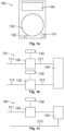
- Fig. 1a shows an example household appliance 100 which may comprise an electronic user interface 104 and a processing room 102 for processing one or more items, such as dishes in case of a dishwasher, a food item in case of an oven, or clothes in case of a washing machine or dryer.
- the appliance 100 comprises one or more electrical components 103 which are configured to provide a processing function for processing the one or more items within the processing room 102.
- Example electrical components 103 are: a heater for heating up the processing room 102 or water used within the processing room 102, or an electrical motor for rotating a washing drum of a washing machine, or an electrical pump for pumping water into or out off the processing room 102.
- the household appliance 100 may further comprise a power supply 101 which is configured to provide electrical power to the different electrical and/or electronic components 103, 104 of the household appliance 100.
- the electrical power may be derived from an external alternating current (AC) supply (such as a 230V AC supply).
- the power supply 101 may comprise one or more AC / DC power converters configured to provide a DC current to one or more DC components of the appliance 100 (such as the electronic user interface 104).
- an AC current may be provided to one or more electrical components 103 of the appliance 100, which may be operated using an AC current (such as the heater).
- Fig. 1b shows an example AC power supply 101 for an AC appliance 100.
- the power supply 101 comprises a first AC supply line 111 (e.g., a phase line) and a second AC supply line 112 (e.g., a neutral line), each conducting an AC current.
- the power supply 101 typically comprises AC switching elements 120 on one or more of the supply lines 111, 112.
- An AC switching element 120 may be configured to galvanically interrupt the respective AC supply line 111, 112.
- the AC switching element 120 may comprise or may be a relay which is controlled using a control circuit 130.
- the power supply 101 of the household appliance 100 is configured to supply electrical circuitry 140 of the household appliance 100, where in the electrical circuitry 140 comprises one or more electrical components 103.
- the one or more AC switching elements 120 may be controlled to interrupt the respective one or more AC supply lines 111, 112 in dependence of the state of the appliance 100.
- the one or more AC switching elements 120 may be controlled to be open, thereby galvanically decoupling the AC supply from the electrical circuitry 140 and thereby increasing the safety of the household appliance 100.
- the household appliance 100 may further comprise one or more AC switching elements 120 for turning on or off an electrical component 103, e.g., a heater (as shown in Fig. 1c ), in the context of the operation of the electrical component 103.
- the control circuit 130 may be configured to close the AC switching element 120 (e.g., the relay) to provide a galvanically conducting connection between the first supply line 211 and the electrical component 103, thereby turning on the electrical component 103.
- the control circuit 130 may be configured to open the AC switching element 120 to galvanically interrupt the connection between the first supply line 211 and the electrical component 103, thereby turning off the electrical component 103.
- the electrical component 103 may be turned on and off in a reliable manner during operation of the household appliance 100.
- Safety powering-off switching is an important safety part of an AC home appliance 100 powered by AC voltage (e.g., a washing machine, an oven, a dryer, etc.).
- AC voltage e.g., a washing machine, an oven, a dryer, etc.
- power-off switching using the one or more AC switching elements 120
- a relay is typically used as an AC switching element 120 of an AC home appliance 100.
- an AC appliance 100 may comprise one or more electrical components 103, such as a heater, which are powered by an AC voltage.
- a relay may be used to turn on and off an AC powered electrical component 103 (as illustrated in Fig. 1c ).
- a relay typically cannot be used in case of DC switching, due to the occurrence of undesired effects during the turn-off process.
- a relatively large current flows through an AC switching element 120 of the appliance 120.
- Turning-off the relay of the AC switching element 120 under load causes an undesirable arcing between the contacts of the relay, eventually leading to contacts that weld shut or contacts that fail due to a buildup of surface damage caused by the destructive arc energy.
- Solid-state relays may be used for switching of DC loads, however, SSRs are typically quite costly.
- a switching circuit which allows for an efficient and reliable safety power-off switching and/or a reliable control switching of a DC current within a DC household appliance 100.
- Fig. 2a shows safety switching circuits 200 for an AC appliance 100, wherein a (safety) switching circuit 200 comprises an AC switching element 120 (in particular a relay) and a control circuit 130 for controlling the AC switching element 120.
- a safety switching circuit 200 may also be referred to as a power-off circuit.
- the control circuit 130 may comprise a control transistor 230 which is controlled using a control signal 233.
- the control transistor 230 may be arranged between a control voltage 231 and a reference voltage 232 (e.g., ground).
- the control transistor 230 may be configured to apply the control voltage 231 to the AC switching element 120 for closing the AC switching element 120, and to decouple the control voltage 231 from the AC switching element 120 for opening the AC switching element 120.
- Fig. 2a shows a (safety) switching circuit 200 for the first AC supply line 111, 211, which is configured to galvanically interrupt the first AC supply line 111, 211. Furthermore, Fig. 2a shows a (safety) switching circuit 200 for the second AC supply line 112, 212, which is configured to galvanically interrupt the second AC supply line 112, 212.
- the AC switching element 120 may be replaced by a semiconductor-based switching element 220, such as a metaloxide semiconductor (MOS) field effect transistor (FET).
- the semiconductor-based switching element 220 is configured to galvanically interrupt a DC supply line 241, 251 (or 242, 252).
- the drive circuitry for controlling the semiconductor-based switching element 220 may comprise a galvanically isolated DC/DC power converter 221 which may comprise a transformer for galvanic isolation.
- the DC/DC power converter 221 may be configured to transfer the drive voltage (generated by the control transistor 230) to the drive unit 222 for driving the semiconductor-based switching element 220.
- the DC/DC power converter 221 may be configured to adjust the level of the drive voltage to the requirements of the drive unit 222.
- the drive unit 222 may be coupled to the control pin (notably to the gate) of the semiconductor-based switching element 220, e.g., via a resistor 223.
- Fig. 2b illustrates a (safety) switching circuit 200 for the first DC supply line 241, 251 (e.g., for the DC+ voltage), which is configured to galvanically interrupt the first DC supply line 241, 251. Furthermore, Fig. 2b shows a (safety) switching circuit 200 for the second DC supply line 242, 252 (e.g., for the DC- voltage), which is configured to galvanically interrupt the second supply line 242, 252.
- the switching circuits 200 in Fig. 2b may be used to replace the corresponding AC switching circuits 200 of Fig. 2a in a one-by-one manner, without the need for replacing the control circuit 130 comprising the control transistor 230.
- the AC switching element 120 (notably the mechanical relay) may be replaced by the semiconductor-based switching element 220 and drive circuity 221, 222, 223 for operating the semiconductor-based switching element 220.
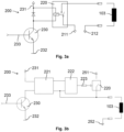
- Fig. 3a shows an (operation) AC switching circuit 200 for operating an electrical component 103, in particular a heater, of the appliance 100.
- the electrical component 103 is operated using an AC current between the first AC supply line 211 and the second AC supply line 212.
- Fig. 3b shows a corresponding (operation) DC switching circuit 200 with a semiconductor-based switching element 220 and its drive circuity 221, 222, 223 for operating the electrical component 103 using a DC current between the first DC supply line 251 and the second DC supply line 252.
- a DC switching circuit 200 which can be used for replacing a corresponding AC switching circuit 200.
- the DC switching circuit 200 may be used for power switching of the DC+ and/or DC- supply lines 241, 242 and for galvanic isolation of the input power part of a household appliance 100 from the internal parts of household appliance 100.
- the DC switching circuit 200 may be used for power switching of a load 103 and for galvanic isolation of the load 103.
Landscapes
- Engineering & Computer Science (AREA)
- Power Engineering (AREA)
- Textile Engineering (AREA)
- Dc-Dc Converters (AREA)
Abstract
Description
- The present document relates to a switching circuit for a household appliance, in particular for a DC (direct current) household appliance.
- A housing appliance, such as a washing machine, a dishwasher or a refrigerator, is typically powered by an AC (alternate current) voltage. The household appliance may comprise one or more switching circuits which are configured to galvanically decouple the household appliance or an electric component of the household appliance from the AC voltage.
- It is expected that in the future, DC household appliances will be available which are directly powered by a DC voltage which is provided by an external DC power supply. The present document addresses the technical problem of providing an efficient and reliable switching circuit for a DC household appliance, in particular such that the switching circuit allows for a one-to-one replacement of a corresponding switching circuit for an AC household appliance. The technical problem is solved by the independent claim. Preferred examples are described in the dependent claims.
- According to an aspect, a household appliance, in particular a DC household appliance, is described. The household appliance may comprise or may be a dishwasher, an oven, a washing machine, a dryer, a beverage machine (such as a coffee machine), a kitchen and/or cooking machine, and/or a vacuum cleaner. The DC household appliance is configured to be operated based on a DC supply voltage that is provided by an external DC supply, which is external to the household appliance. The DC supply voltage is preferably 100V or higher, in particular 200V or higher. Furthermore, the DC household appliance may be designed such that it is transformable into a corresponding AC household appliance in an efficient manner.
- The appliance comprises a DC power supply which is configured to provide the DC supply voltage between a first DC supply line (e.g., a DC+ line) and a second DC supply line (e.g., a DC- line) from the external DC supply. By way of example, the appliance may comprise a power plug for coupling the DC supply lines with a corresponding power plug of the external DC supply. The first and second DC supply lines may be directly connected to the power plug of the appliance.
- Furthermore, the appliance comprises an electrical component, in particular an electrical power component, which is configured to be operated by the DC supply voltage (possibly without the need of performing a (DC/DC) voltage conversion). The household appliance may comprise a processing room configured to take up an item (e.g., a dish, a food item or clothes) which is processed by the household appliance. Example processing, which is performed within the processing room, may be: washing, cleaning, drying, baking, cooking, brewing, etc. The processing room may be the drum of a washing machine or dryer, or may be the inside of a dishwasher or oven. The electrical component may be configured to provide a processing function (such as heating, pumping or actuating) which contributes to or which corresponds to the processing of the item within the processing room.
- By way of example, the electrical component may comprise or may be a heater configured to heat a fluid (e.g., water or air) and/or to heat the processing room of the household appliance. Alternatively, or in addition, the electrical component may comprise or may be an electrical motor configured to move a mechanical component (e.g., the drum) of the household appliance. Alternatively, or in addition, the electrical component may comprise or may be an electrical pump or ventilator configured to pump a fluid (e.g., water or air) into and/or out of a processing room of the household appliance. The electrical component may be such that the electrical component consumes 20% or more, in particular 50% or more, of the total electrical power consumption of the appliance (in average). Alternatively, or in addition, the electrical component may be a power component of the appliance.
- The electrical component may be configured to be operated both by the DC supply voltage and by an AC supply voltage (e.g., a 230V voltage) between a first AC supply line (e.g., a phase line) and a second AC supply line (e.g., a neutral line). As such, the same electrical component may be used within the DC variant and the AC variant of the household appliance.
- Furthermore, the appliance comprises at least one DC switching circuit comprising a semiconductor-based switching element which is configured to galvanically interrupt the first DC supply line or the second DC supply line in reaction to a control signal. The switching element may comprise a transistor, in particular a field effect transistor (FET) such as a metaloxide semiconductor (MOS) FET. The switching circuit may be a power-off circuit.
- By making use of a semiconductor-based switching element within the switching circuit of a DC household appliance, power-off switching may be provided in a safe and efficient manner.
- As indicated above, the household appliance may be designed such that the DC variant and the AC variant of the appliance may be provided in an efficient manner. In particular, the household appliance may be designed such that the DC household appliance is transformable into a corresponding AC household appliance (solely) by replacing the DC power supply by a corresponding AC power supply configured to provide the AC supply voltage from an external AC supply (e.g., a 230V supply), and by replacing the DC switching circuit by a corresponding AC switching circuit (e.g., comprising a mechanical relay). As a result of this, AC and DC variants of a household appliance may be provided in a particularly efficient manner.
- The household appliance may comprise a first safety DC switching circuit (notably a DC power-off circuit) which comprises a semiconductor-based switching element that is arranged between a first external DC supply line directly coupled with the external DC supply (e.g., via a power plug) and a first internal DC supply line coupled with the electrical component. The switching element of the first safety DC switching circuit may be configured to galvanically couple the first external DC supply line with or to galvanically decouple the first external DC supply line from the first internal supply line, in dependence of a safety control signal.
- Alternatively, or in addition, the household appliance may comprise a second safety DC switching circuit (notably a DC power-off circuit) comprising a semiconductor-based switching element that is arranged between a second external DC supply line directly coupled with the external DC supply (e.g., via a power plug) and a second internal DC supply line coupled with the electrical component. The switching element of the second safety DC switching circuit may be configured to galvanically couple the second external DC supply line with or to galvanically decouple the second external DC supply line from the second internal supply line, in dependence of a safety control signal.
- Hence, the appliance may comprise one or more switching circuits for providing safety power-off switching. For this purpose, the household appliance may comprise a control unit which is configured to detect a safety relevant state of the household appliance. The safety relevant state may comprise a malfunction of the household appliance and/or an open state of the processing room (notably of the door of the processing room) of the household appliance. In reaction to this, a safety control signal may be generated, which is directed at opening the switching element of the first safety DC switching circuit and/or of the second safety DC switching circuit. As a result of this, a safe operation of the household appliance is enabled. In particular, the appliance may be decoupled from the external DC supply in an efficient and reliable manner.
- The household appliance may comprise an operation DC switching circuit comprising a semiconductor-based switching element that is arranged between the first internal DC supply line and the electrical component. The operation DC switching circuit may change its state (between on-state and off-state), possibly repeatedly, during operation of the household appliance. The electrical component may be arranged between the first internal DC supply line and the second internal DC supply line. The switching element of the operation DC switching circuit may be configured to galvanically couple the first internal DC supply line with or to galvanically decouple the first internal DC supply line from the electrical component, in dependence of an operation control signal. The control unit may be configured to generate the operation control signal in dependence of an operating program of the household appliance for providing a processing function of the electrical component. Hence, the electrical component may be operated in an efficient and reliable manner using the DC supply voltage.
- A DC switching circuit of the household appliance may comprise a control circuit which is configured to generate a drive signal for opening or closing the semiconductor-based switching element in dependence of the control signal. The control circuit may comprise a control transistor which is arranged between a control voltage and a reference voltage and which is opened or closed in dependence of the control signal. In a preferred example, the drive signal is configured to open or close a mechanical relay which replaces the semiconductor-based switching element in a corresponding AC household appliance. As a result of this, an AC and a DC variant of the appliance may be provided in a particular efficient manner (as the control circuit of the one or more switching circuits may be used in both variants).
- The DC switching circuit may comprise drive circuitry which is configured to convert the drive signal into a gate signal for controlling the semiconductor-based switching element of the DC power-of circuit. The drive circuitry may comprise a DC/DC power converter, in particular a galvanically isolated DC/DC power converter, which is configured to adapt the voltage level of the drive signal (providing an output signal at a different voltage level than the drive signal). By making use of a DC/DC power converter, a DC switching circuit for replacing a corresponding AC switching circuit may be provided in a particular efficient and reliable manner.
- The drive circuitry may further comprise a drive unit which is configured to generate the gate signal based on the output signal of the DC/DC power converter, thereby controlling the semiconductor-based switching element in a reliable manner.
- It should be noted that the systems including its preferred embodiments as outlined in the present document may be used stand-alone or in combination with the other systems disclosed in this document. In addition, the features outlined in the context of a system are also applicable to a corresponding method. Furthermore, all aspects of the systems outlined in the present document may be arbitrarily combined. In particular, the features of the claims may be combined with one another in an arbitrary manner.
- The invention is explained below in an exemplary manner with reference to the accompanying drawings, wherein
- Figure 1a
- shows an example household appliance;
- Figure 1b
- shows an example power supply of a household appliance;
- Figure 1c
- shows an example electrical component of a household appliance;
- Figure 2a
- shows example AC switching circuits for the supply lines of an AC household appliance;
- Figure 2b
- shows example DC switching circuits for the supply lines of a DC household appliance;
- Figure 3a
- shows an example AC switching circuit for the supply of an electrical component of an AC household appliance; and
- Figure 3b
- shows an example DC switching circuit for the supply of an electrical component of a DC household appliance.
- As outlined above, the present document is directed at providing an efficient and reliable DC switching circuit for a DC household appliance, in particular such that it allows for a one-to-one replacement of a corresponding AC switching circuit in a corresponding AC household appliance. In this context
Fig. 1a shows anexample household appliance 100 which may comprise anelectronic user interface 104 and aprocessing room 102 for processing one or more items, such as dishes in case of a dishwasher, a food item in case of an oven, or clothes in case of a washing machine or dryer. Furthermore, theappliance 100 comprises one or moreelectrical components 103 which are configured to provide a processing function for processing the one or more items within theprocessing room 102. Exampleelectrical components 103 are: a heater for heating up theprocessing room 102 or water used within theprocessing room 102, or an electrical motor for rotating a washing drum of a washing machine, or an electrical pump for pumping water into or out off theprocessing room 102. - The
household appliance 100 may further comprise apower supply 101 which is configured to provide electrical power to the different electrical and/orelectronic components household appliance 100. The electrical power may be derived from an external alternating current (AC) supply (such as a 230V AC supply). In such a case, thepower supply 101 may comprise one or more AC / DC power converters configured to provide a DC current to one or more DC components of the appliance 100 (such as the electronic user interface 104). Furthermore, an AC current may be provided to one or moreelectrical components 103 of theappliance 100, which may be operated using an AC current (such as the heater). -
Fig. 1b shows an exampleAC power supply 101 for anAC appliance 100. Thepower supply 101 comprises a first AC supply line 111 (e.g., a phase line) and a second AC supply line 112 (e.g., a neutral line), each conducting an AC current. For safety reasons, thepower supply 101 typically comprisesAC switching elements 120 on one or more of thesupply lines AC switching element 120 may be configured to galvanically interrupt the respectiveAC supply line AC switching element 120 may comprise or may be a relay which is controlled using acontrol circuit 130. - As indicated above, the
power supply 101 of thehousehold appliance 100 is configured to supplyelectrical circuitry 140 of thehousehold appliance 100, where in theelectrical circuitry 140 comprises one or moreelectrical components 103. The one or moreAC switching elements 120 may be controlled to interrupt the respective one or moreAC supply lines appliance 100. By way of example, if it is detected that theprocessing room 102 of theappliance 100 is open (because the door to theprocessing room 102 is open), the one or moreAC switching elements 120 may be controlled to be open, thereby galvanically decoupling the AC supply from theelectrical circuitry 140 and thereby increasing the safety of thehousehold appliance 100. - The
household appliance 100 may further comprise one or moreAC switching elements 120 for turning on or off anelectrical component 103, e.g., a heater (as shown inFig. 1c ), in the context of the operation of theelectrical component 103. Thecontrol circuit 130 may be configured to close the AC switching element 120 (e.g., the relay) to provide a galvanically conducting connection between thefirst supply line 211 and theelectrical component 103, thereby turning on theelectrical component 103. Furthermore, thecontrol circuit 130 may be configured to open theAC switching element 120 to galvanically interrupt the connection between thefirst supply line 211 and theelectrical component 103, thereby turning off theelectrical component 103. Hence, theelectrical component 103 may be turned on and off in a reliable manner during operation of thehousehold appliance 100. - Safety powering-off switching, as illustrated in
Fig. 1b , is an important safety part of anAC home appliance 100 powered by AC voltage (e.g., a washing machine, an oven, a dryer, etc.). In case of a malfunction of the appliance 100 (e.g., a freeze of the microcontroller of the appliance 100) power-off switching (using the one or more AC switching elements 120) ensures the disconnection of the phase conductor (L) 111 and/or the neutral conductor (N) 112 of the AC supply from theappliance 100. A relay is typically used as anAC switching element 120 of anAC home appliance 100. - Furthermore, an
AC appliance 100 may comprise one or moreelectrical components 103, such as a heater, which are powered by an AC voltage. A relay may be used to turn on and off an AC powered electrical component 103 (as illustrated inFig. 1c ). - A relay typically cannot be used in case of DC switching, due to the occurrence of undesired effects during the turn-off process. During operation of a DC home appliance a relatively large current flows through an
AC switching element 120 of theappliance 120. Turning-off the relay of theAC switching element 120 under load causes an undesirable arcing between the contacts of the relay, eventually leading to contacts that weld shut or contacts that fail due to a buildup of surface damage caused by the destructive arc energy. Solid-state relays (SSR) may be used for switching of DC loads, however, SSRs are typically quite costly. - In the present document, a switching circuit is described which allows for an efficient and reliable safety power-off switching and/or a reliable control switching of a DC current within a
DC household appliance 100. -
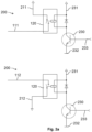
Fig. 2a showssafety switching circuits 200 for anAC appliance 100, wherein a (safety) switchingcircuit 200 comprises an AC switching element 120 (in particular a relay) and acontrol circuit 130 for controlling theAC switching element 120. Asafety switching circuit 200 may also be referred to as a power-off circuit. Thecontrol circuit 130 may comprise acontrol transistor 230 which is controlled using acontrol signal 233. Thecontrol transistor 230 may be arranged between acontrol voltage 231 and a reference voltage 232 (e.g., ground). Thecontrol transistor 230 may be configured to apply thecontrol voltage 231 to theAC switching element 120 for closing theAC switching element 120, and to decouple thecontrol voltage 231 from theAC switching element 120 for opening theAC switching element 120. -
Fig. 2a shows a (safety) switchingcircuit 200 for the firstAC supply line AC supply line Fig. 2a shows a (safety) switchingcircuit 200 for the secondAC supply line AC supply line - As illustrated in
Fig. 2b , theAC switching element 120 may be replaced by a semiconductor-basedswitching element 220, such as a metaloxide semiconductor (MOS) field effect transistor (FET). The semiconductor-basedswitching element 220 is configured to galvanically interrupt aDC supply line 241, 251 (or 242, 252). The drive circuitry for controlling the semiconductor-basedswitching element 220 may comprise a galvanically isolated DC/DC power converter 221 which may comprise a transformer for galvanic isolation. The DC/DC power converter 221 may be configured to transfer the drive voltage (generated by the control transistor 230) to thedrive unit 222 for driving the semiconductor-basedswitching element 220. Furthermore, the DC/DC power converter 221 may be configured to adjust the level of the drive voltage to the requirements of thedrive unit 222. Thedrive unit 222 may be coupled to the control pin (notably to the gate) of the semiconductor-basedswitching element 220, e.g., via aresistor 223. -
Fig. 2b illustrates a (safety) switchingcircuit 200 for the firstDC supply line 241, 251 (e.g., for the DC+ voltage), which is configured to galvanically interrupt the firstDC supply line Fig. 2b shows a (safety) switchingcircuit 200 for the secondDC supply line 242, 252 (e.g., for the DC- voltage), which is configured to galvanically interrupt thesecond supply line - The switching
circuits 200 inFig. 2b may be used to replace the correspondingAC switching circuits 200 ofFig. 2a in a one-by-one manner, without the need for replacing thecontrol circuit 130 comprising thecontrol transistor 230. In particular, the AC switching element 120 (notably the mechanical relay) may be replaced by the semiconductor-basedswitching element 220 and drivecircuity switching element 220. -
Fig. 3a shows an (operation)AC switching circuit 200 for operating anelectrical component 103, in particular a heater, of theappliance 100. InFig. 3a theelectrical component 103 is operated using an AC current between the firstAC supply line 211 and the secondAC supply line 212.Fig. 3b shows a corresponding (operation)DC switching circuit 200 with a semiconductor-basedswitching element 220 and itsdrive circuity electrical component 103 using a DC current between the firstDC supply line 251 and the secondDC supply line 252. - Hence, a
DC switching circuit 200 is described, which can be used for replacing a correspondingAC switching circuit 200. In particular, theDC switching circuit 200 may be used for power switching of the DC+ and/or DC-supply lines household appliance 100 from the internal parts ofhousehold appliance 100. Alternatively, theDC switching circuit 200 may be used for power switching of aload 103 and for galvanic isolation of theload 103. - It should be noted that the description and drawings merely illustrate the principles of the proposed methods and systems. Those skilled in the art will be able to implement various arrangements that, although not explicitly described or shown herein, embody the principles of the invention and are included within its spirit and scope. Furthermore, all examples and embodiment outlined in the present document are principally intended expressly to be only for explanatory purposes to help the reader in understanding the principles of the proposed methods and systems. Furthermore, all statements herein providing principles, aspects, and embodiments of the invention, as well as specific examples thereof, are intended to encompass equivalents thereof.
Claims (15)
- A household appliance (100), comprising,- a DC power supply configured to provide a DC supply voltage between a first DC supply line (241, 251) and a second DC supply line (242, 252) from an external DC supply, which is external to the household appliance (100);- an electrical component (103) which is configured to be operated by the DC supply voltage; and- at least one DC switching circuit (200) comprising a semiconductor-based switching element (220) which is configured to galvanically interrupt the first DC supply line (241, 251) or the second DC supply line (242, 252) in reaction to a control signal (233).
- The household appliance (100) according to claim 1, wherein the household appliance (100) comprises- a first safety DC switching circuit (200) comprising a semiconductor-based switching element (220) which is arranged between a first external DC supply line (241) directly coupled with the external DC supply and a first internal DC supply line (251) coupled with the electrical component (103); wherein the switching element (220) of the first safety DC switching circuit (200) is configured to galvanically couple the first external DC supply line (241) with or to galvanically decouple the first external DC supply line (241) from the first internal supply line (251), in dependence of a safety control signal (233); and/or- a second safety DC switching circuit (200) comprising a semiconductor-based switching element (220) which is arranged between a second external DC supply line (242) directly coupled with the external DC supply and a second internal DC supply line (252) coupled with the electrical component (103); wherein the switching element (220) of the second safety DC switching circuit (200) is configured to galvanically couple the second external DC supply line (242) with or to galvanically decouple the second external DC supply line (242) from the second internal supply line (252), in dependence of a safety control signal (233).
- The household appliance (100) according to claim 2, wherein the household appliance (100) comprises a control unit configured to- detect a safety relevant state of the household appliance (100); wherein, in particular, the safety relevant state comprises- a malfunction of the household appliance (100); and/or- an open state of a processing room (102) of the household appliance (100); and- in reaction to this, generate a safety control signal (233) which is directed at opening the switching element (220) of the first safety DC switching circuit (200) and/or of the second safety DC switching circuit (200).
- The household appliance (100) according to any of the previous claims, wherein- the household appliance (100) comprises an operation DC switching circuit (200) comprising a semiconductor-based switching element (220) which is arranged between a first internal DC supply line (251) and the electrical component (103);- the electrical component (103) is arranged between the first internal DC supply line (251) and a second internal DC supply line (252); and- the switching element (220) of the operation DC switching circuit (200) is configured to galvanically couple the first internal DC supply line (251) with or to galvanically decouple the first internal DC supply line (251) from the electrical component (103), in dependence of an operation control signal (233).
- The household appliance (100) according to claim 4, wherein the household appliance (100) comprises a control unit configured to generate the operation control signal (233) in dependence of an operating program of the household appliance (100) for providing a processing function of the electrical component (103).
- The household appliance (100) according to any of the previous claims, wherein- the DC switching circuit (200) comprises a control circuit (130) configured to generate a drive signal for opening or closing the semiconductor-based switching element (220) in dependence of the control signal (233); and- in particular the drive signal is configured to open or close a mechanical relay (120) replacing the semiconductor-based switching element (220) in a corresponding AC household appliance (100).
- The household appliance (100) according to claim 6, wherein- the DC switching circuit (200) comprises drive circuitry (221, 222, 223) configured to convert the drive signal into a gate signal for controlling the semiconductor-based switching element (220); and- the drive circuitry (221, 222, 223) comprises a DC/DC power converter (221), in particular a galvanically isolated DC/DC power converter, configured to adapt a voltage level of the drive signal.
- The household appliance (100) according to claim 7, wherein the drive circuitry (221, 222, 223) comprises a drive unit (222) configured to generate the gate signal based on an output signal of the DC/DC power converter (221).
- The household appliance (100) according to any of claims 6 to 8, wherein the control circuit (130) comprises a control transistor (230) which is arranged between a control voltage (231) and a reference voltage (232) and which is opened or closed in dependence of the control signal (233).
- The household appliance (100) according to any of the previous claims, wherein the DC supply voltage is 100V or higher.
- The household appliance (100) according to any of the previous claims, wherein- the household appliance (100) comprises a processing room (102) configured to take up an item which is processed by the household appliance (100); and- the electrical component (103) is configured to provide a processing function contributing to the processing of the item within the processing room (102).
- The household appliance (100) according to any of the previous claims, wherein the electrical component (103) comprises,- a heater configured to heat a fluid and/or to heat a processing room (102) of the household appliance (100);- an electrical motor configured to move a mechanical component of the household appliance (100); and/or- an electrical pump configured to pump a fluid into and/or out of a processing room (102) of the household appliance (100).
- The household appliance (100) according to any of the previous claims, wherein the electrical component (103) is configured to be operated both by the DC supply voltage and by an AC supply voltage between a first AC supply line (111, 211) and a second AC supply line (112, 212).
- The household appliance (100) according to any of the previous claims, wherein the household appliance (100) is designed such that the household appliance (100) is transformable into a corresponding AC household appliance (100) by- replacing the DC power supply by a corresponding AC power supply (101) configured to provide an AC supply voltage from an external AC supply; and- replacing the DC switching circuit (200) by a corresponding AC switching circuit (200).
- The household appliance (100) according to any of the previous claims, wherein the household appliance (100) comprises a dishwasher, an oven, a washing machine, a dryer, a beverage machine, a kitchen and/or cooking machine.
Priority Applications (2)
| Application Number | Priority Date | Filing Date | Title |
|---|---|---|---|
| EP22159321.3A EP4239821A1 (en) | 2022-03-01 | 2022-03-01 | Dc household appliance with a switching circuit |
| US18/176,613 US20230283181A1 (en) | 2022-03-01 | 2023-03-01 | Dc household appliance with a switching circuit |
Applications Claiming Priority (1)
| Application Number | Priority Date | Filing Date | Title |
|---|---|---|---|
| EP22159321.3A EP4239821A1 (en) | 2022-03-01 | 2022-03-01 | Dc household appliance with a switching circuit |
Publications (1)
| Publication Number | Publication Date |
|---|---|
| EP4239821A1 true EP4239821A1 (en) | 2023-09-06 |
Family
ID=80623569
Family Applications (1)
| Application Number | Title | Priority Date | Filing Date |
|---|---|---|---|
| EP22159321.3A Pending EP4239821A1 (en) | 2022-03-01 | 2022-03-01 | Dc household appliance with a switching circuit |
Country Status (2)
| Country | Link |
|---|---|
| US (1) | US20230283181A1 (en) |
| EP (1) | EP4239821A1 (en) |
Citations (3)
| Publication number | Priority date | Publication date | Assignee | Title |
|---|---|---|---|---|
| US6448541B1 (en) * | 1998-11-13 | 2002-09-10 | Samsung Electronics Co., Ltd. | AC/DC type microwave oven |
| CN105703353A (en) * | 2016-03-17 | 2016-06-22 | 中山市多威尔电器有限公司 | AC and DC power supply system automatic switching device for solar DC refrigerator |
| CN206960931U (en) * | 2017-05-27 | 2018-02-02 | 何志雄 | Vehicle-mounted coffee maker control circuit |
-
2022
- 2022-03-01 EP EP22159321.3A patent/EP4239821A1/en active Pending
-
2023
- 2023-03-01 US US18/176,613 patent/US20230283181A1/en active Pending
Patent Citations (3)
| Publication number | Priority date | Publication date | Assignee | Title |
|---|---|---|---|---|
| US6448541B1 (en) * | 1998-11-13 | 2002-09-10 | Samsung Electronics Co., Ltd. | AC/DC type microwave oven |
| CN105703353A (en) * | 2016-03-17 | 2016-06-22 | 中山市多威尔电器有限公司 | AC and DC power supply system automatic switching device for solar DC refrigerator |
| CN206960931U (en) * | 2017-05-27 | 2018-02-02 | 何志雄 | Vehicle-mounted coffee maker control circuit |
Also Published As
| Publication number | Publication date |
|---|---|
| US20230283181A1 (en) | 2023-09-07 |
Similar Documents
| Publication | Publication Date | Title |
|---|---|---|
| US8422251B2 (en) | Circuit arrangements for operating a household appliance | |
| US9817052B2 (en) | Method and circuit for determining dispersion of electric power towards ground in electric appliances | |
| US20180259582A1 (en) | Household appliance | |
| CN101897093B (en) | Circuit configuration for operating a household appliance | |
| US7045917B2 (en) | Circuit arrangement for an electric appliance | |
| CN110462955B (en) | Disconnecting a household appliance from an electrical supply network | |
| EP4239821A1 (en) | Dc household appliance with a switching circuit | |
| US9186035B2 (en) | Method of operating a heater in a dishwasher | |
| CN101581530A (en) | Start circuit of microwave oven and refrigerator combined machine and control method thereof | |
| CN101248706A (en) | Electric device and heating cooking device | |
| US20110234018A1 (en) | Control circuit for an electronic household appliance | |
| RU2666155C1 (en) | Switching device for electronic power supply including electronic control unit, household appliance and method of its operation | |
| US9737192B2 (en) | Door latch interruption upon detection of current leakage | |
| CN102239636A (en) | Appliance control system with a zero crossing detecting circuit | |
| CN208094826U (en) | low-power standby circuit and induction cooker | |
| CN110840352A (en) | Dish washer control system | |
| CN108337760A (en) | Meal is ripe to be automatically stopped heating microwave oven | |
| CN210518903U (en) | Low-power standby circuit and induction cooker | |
| EP2466606B1 (en) | Electronic circuitry for household appliances | |
| CN220961696U (en) | Detection circuit for household appliance, control system and household appliance | |
| CN213547343U (en) | Control circuit for reducing standby power consumption of cooking appliance and cooking appliance | |
| US20220409006A1 (en) | Water-using domestic appliance and method for operating a water-using domestic appliance | |
| JP3480430B2 (en) | Home appliances | |
| CN1980506A (en) | Internal lighting device of domestic electric product, and control method therefor | |
| RU2575219C2 (en) | Electric household appliance for products processing |
Legal Events
| Date | Code | Title | Description |
|---|---|---|---|
| PUAI | Public reference made under article 153(3) epc to a published international application that has entered the european phase |
Free format text: ORIGINAL CODE: 0009012 |
|
| STAA | Information on the status of an ep patent application or granted ep patent |
Free format text: STATUS: THE APPLICATION HAS BEEN PUBLISHED |
|
| AK | Designated contracting states |
Kind code of ref document: A1 Designated state(s): AL AT BE BG CH CY CZ DE DK EE ES FI FR GB GR HR HU IE IS IT LI LT LU LV MC MK MT NL NO PL PT RO RS SE SI SK SM TR |
|
| STAA | Information on the status of an ep patent application or granted ep patent |
Free format text: STATUS: REQUEST FOR EXAMINATION WAS MADE |
|
| 17P | Request for examination filed |
Effective date: 20240306 |
|
| RBV | Designated contracting states (corrected) |
Designated state(s): AL AT BE BG CH CY CZ DE DK EE ES FI FR GB GR HR HU IE IS IT LI LT LU LV MC MK MT NL NO PL PT RO RS SE SI SK SM TR |