EP4239779A1 - Secondary battery - Google Patents
Secondary battery Download PDFInfo
- Publication number
- EP4239779A1 EP4239779A1 EP22788484.8A EP22788484A EP4239779A1 EP 4239779 A1 EP4239779 A1 EP 4239779A1 EP 22788484 A EP22788484 A EP 22788484A EP 4239779 A1 EP4239779 A1 EP 4239779A1
- Authority
- EP
- European Patent Office
- Prior art keywords
- secondary battery
- vent member
- kgf
- battery according
- sealing strength
- Prior art date
- Legal status (The legal status is an assumption and is not a legal conclusion. Google has not performed a legal analysis and makes no representation as to the accuracy of the status listed.)
- Pending
Links
Images


Classifications
-
- C—CHEMISTRY; METALLURGY
- C08—ORGANIC MACROMOLECULAR COMPOUNDS; THEIR PREPARATION OR CHEMICAL WORKING-UP; COMPOSITIONS BASED THEREON
- C08F—MACROMOLECULAR COMPOUNDS OBTAINED BY REACTIONS ONLY INVOLVING CARBON-TO-CARBON UNSATURATED BONDS
- C08F210/00—Copolymers of unsaturated aliphatic hydrocarbons having only one carbon-to-carbon double bond
- C08F210/16—Copolymers of ethene with alpha-alkenes, e.g. EP rubbers
-
- H—ELECTRICITY
- H01—ELECTRIC ELEMENTS
- H01M—PROCESSES OR MEANS, e.g. BATTERIES, FOR THE DIRECT CONVERSION OF CHEMICAL ENERGY INTO ELECTRICAL ENERGY
- H01M50/00—Constructional details or processes of manufacture of the non-active parts of electrochemical cells other than fuel cells, e.g. hybrid cells
- H01M50/30—Arrangements for facilitating escape of gases
- H01M50/375—Vent means sensitive to or responsive to temperature
-
- C—CHEMISTRY; METALLURGY
- C08—ORGANIC MACROMOLECULAR COMPOUNDS; THEIR PREPARATION OR CHEMICAL WORKING-UP; COMPOSITIONS BASED THEREON
- C08F—MACROMOLECULAR COMPOUNDS OBTAINED BY REACTIONS ONLY INVOLVING CARBON-TO-CARBON UNSATURATED BONDS
- C08F210/00—Copolymers of unsaturated aliphatic hydrocarbons having only one carbon-to-carbon double bond
- C08F210/02—Ethene
-
- H—ELECTRICITY
- H01—ELECTRIC ELEMENTS
- H01M—PROCESSES OR MEANS, e.g. BATTERIES, FOR THE DIRECT CONVERSION OF CHEMICAL ENERGY INTO ELECTRICAL ENERGY
- H01M50/00—Constructional details or processes of manufacture of the non-active parts of electrochemical cells other than fuel cells, e.g. hybrid cells
- H01M50/10—Primary casings; Jackets or wrappings
- H01M50/102—Primary casings; Jackets or wrappings characterised by their shape or physical structure
- H01M50/105—Pouches or flexible bags
-
- H—ELECTRICITY
- H01—ELECTRIC ELEMENTS
- H01M—PROCESSES OR MEANS, e.g. BATTERIES, FOR THE DIRECT CONVERSION OF CHEMICAL ENERGY INTO ELECTRICAL ENERGY
- H01M50/00—Constructional details or processes of manufacture of the non-active parts of electrochemical cells other than fuel cells, e.g. hybrid cells
- H01M50/10—Primary casings; Jackets or wrappings
- H01M50/172—Arrangements of electric connectors penetrating the casing
- H01M50/174—Arrangements of electric connectors penetrating the casing adapted for the shape of the cells
- H01M50/178—Arrangements of electric connectors penetrating the casing adapted for the shape of the cells for pouch or flexible bag cells
-
- H—ELECTRICITY
- H01—ELECTRIC ELEMENTS
- H01M—PROCESSES OR MEANS, e.g. BATTERIES, FOR THE DIRECT CONVERSION OF CHEMICAL ENERGY INTO ELECTRICAL ENERGY
- H01M50/00—Constructional details or processes of manufacture of the non-active parts of electrochemical cells other than fuel cells, e.g. hybrid cells
- H01M50/10—Primary casings; Jackets or wrappings
- H01M50/183—Sealing members
- H01M50/19—Sealing members characterised by the material
- H01M50/193—Organic material
-
- H—ELECTRICITY
- H01—ELECTRIC ELEMENTS
- H01M—PROCESSES OR MEANS, e.g. BATTERIES, FOR THE DIRECT CONVERSION OF CHEMICAL ENERGY INTO ELECTRICAL ENERGY
- H01M50/00—Constructional details or processes of manufacture of the non-active parts of electrochemical cells other than fuel cells, e.g. hybrid cells
- H01M50/30—Arrangements for facilitating escape of gases
- H01M50/342—Non-re-sealable arrangements
- H01M50/3425—Non-re-sealable arrangements in the form of rupturable membranes or weakened parts, e.g. pierced with the aid of a sharp member
-
- C—CHEMISTRY; METALLURGY
- C08—ORGANIC MACROMOLECULAR COMPOUNDS; THEIR PREPARATION OR CHEMICAL WORKING-UP; COMPOSITIONS BASED THEREON
- C08F—MACROMOLECULAR COMPOUNDS OBTAINED BY REACTIONS ONLY INVOLVING CARBON-TO-CARBON UNSATURATED BONDS
- C08F2500/00—Characteristics or properties of obtained polyolefins; Use thereof
- C08F2500/08—Low density, i.e. < 0.91 g/cm3
-
- C—CHEMISTRY; METALLURGY
- C08—ORGANIC MACROMOLECULAR COMPOUNDS; THEIR PREPARATION OR CHEMICAL WORKING-UP; COMPOSITIONS BASED THEREON
- C08F—MACROMOLECULAR COMPOUNDS OBTAINED BY REACTIONS ONLY INVOLVING CARBON-TO-CARBON UNSATURATED BONDS
- C08F2500/00—Characteristics or properties of obtained polyolefins; Use thereof
- C08F2500/33—Crystallisation temperature [Tc]
-
- C—CHEMISTRY; METALLURGY
- C08—ORGANIC MACROMOLECULAR COMPOUNDS; THEIR PREPARATION OR CHEMICAL WORKING-UP; COMPOSITIONS BASED THEREON
- C08F—MACROMOLECULAR COMPOUNDS OBTAINED BY REACTIONS ONLY INVOLVING CARBON-TO-CARBON UNSATURATED BONDS
- C08F2500/00—Characteristics or properties of obtained polyolefins; Use thereof
- C08F2500/34—Melting point [Tm]
-
- H—ELECTRICITY
- H01—ELECTRIC ELEMENTS
- H01M—PROCESSES OR MEANS, e.g. BATTERIES, FOR THE DIRECT CONVERSION OF CHEMICAL ENERGY INTO ELECTRICAL ENERGY
- H01M2200/00—Safety devices for primary or secondary batteries
- H01M2200/10—Temperature sensitive devices
-
- H—ELECTRICITY
- H01—ELECTRIC ELEMENTS
- H01M—PROCESSES OR MEANS, e.g. BATTERIES, FOR THE DIRECT CONVERSION OF CHEMICAL ENERGY INTO ELECTRICAL ENERGY
- H01M50/00—Constructional details or processes of manufacture of the non-active parts of electrochemical cells other than fuel cells, e.g. hybrid cells
- H01M50/10—Primary casings; Jackets or wrappings
- H01M50/116—Primary casings; Jackets or wrappings characterised by the material
- H01M50/124—Primary casings; Jackets or wrappings characterised by the material having a layered structure
- H01M50/126—Primary casings; Jackets or wrappings characterised by the material having a layered structure comprising three or more layers
- H01M50/129—Primary casings; Jackets or wrappings characterised by the material having a layered structure comprising three or more layers with two or more layers of only organic material
-
- Y—GENERAL TAGGING OF NEW TECHNOLOGICAL DEVELOPMENTS; GENERAL TAGGING OF CROSS-SECTIONAL TECHNOLOGIES SPANNING OVER SEVERAL SECTIONS OF THE IPC; TECHNICAL SUBJECTS COVERED BY FORMER USPC CROSS-REFERENCE ART COLLECTIONS [XRACs] AND DIGESTS
- Y02—TECHNOLOGIES OR APPLICATIONS FOR MITIGATION OR ADAPTATION AGAINST CLIMATE CHANGE
- Y02E—REDUCTION OF GREENHOUSE GAS [GHG] EMISSIONS, RELATED TO ENERGY GENERATION, TRANSMISSION OR DISTRIBUTION
- Y02E60/00—Enabling technologies; Technologies with a potential or indirect contribution to GHG emissions mitigation
- Y02E60/10—Energy storage using batteries
Definitions
- the present disclosure relates to a secondary battery, and more particularly, to a secondary battery having a vent member.
- Secondary batteries are highly applicable to various products and exhibit superior electrical properties such as high energy density, etc. Secondary batteries are commonly used not only in portable devices but also in electric vehicles (EVs) or hybrid electric vehicles (HEVs) driven by electrical power sources. The secondary battery is drawing attentions as a new energy source for enhancing environment friendliness and energy efficiency in that the use of fossil fuels can be reduced greatly and no byproduct is generated during energy consumption.
- EVs electric vehicles
- HEVs hybrid electric vehicles
- Secondary batteries widely used at present include lithium ion batteries, lithium polymer batteries, nickel cadmium batteries, nickel hydrogen batteries, nickel zinc batteries and the like.
- the secondary battery generally has a structure in which an electrode assembly including at least one unit cell having a positive electrode/separator/negative electrode structure is accommodated in a case of a laminate sheet in which an outer layer, a metal barrier layer and a sealant layer are sequentially laminated, and a sealant resin of the sealant layer is fused to seal the electrode assembly.
- the battery may ignite due to various causes such as a short circuit inside the secondary battery, overcharge or overdischarge, temperature control, or the like. At this time, thermal propagation where the temperature inside the secondary battery rises rapidly and simultaneously the heat is transferred to neighboring battery cells may be generated, which may further increase the fire.
- the directional venting characteristic is required to discharge the gas in one direction.
- the conventional secondary battery has a problem in that it is difficult to induce gas discharge in a specific direction.
- the present disclosure is directed to providing a secondary battery with improved safety by inducing gas discharge in a specific direction.
- a secondary battery may include an electrode assembly; an electrode lead attached to the electrode assembly; a case configured to receive the electrode assembly therein; a lead film configured to surround a part of an outer surface of the electrode lead and interposed between the electrode lead and the case; a vent region formed in at least a part of the case; and a vent member inserted into the vent region and configured to contain linear low-density polyethylene having a poly dispersity index (PDI) of 4 or less.
- the vent member has a maximum sealing strength of less than 6 kgf/15 mm at 100°C or above and a maximum sealing strength of 6 kgf/15 mm or more at room temperature to 60°C.
- the vent member may have an average sealing strength of less than 4.5 kgf/15 mm at 100°C or above.
- the vent member may have an average sealing strength of 4.5 kgf/15 mm or more at room temperature to 60°C.
- the case may include a sealing portion formed to seal the electrode assembly.
- the sealing portion may contain a sealant resin.
- the vent member containing the linear low-density polyethylene having a comonomer with a carbon number of 6 or more may have a lower melting point than the sealant resin.
- the vent member may melt at 100°C to 120°C to vent gases.
- the vent member may be vented at a pressure of 1.5 atm or more.
- the linear low-density polyethylene may be polymerized in the presence of a metallocene catalyst.
- a difference between a crystallization temperature of the sealant resin and a crystallization temperature of the linear low-density polyethylene may be 10°C or less.
- the linear low-density polyethylene may have a crystallization temperature of 90°C to 115°C.
- the linear low-density polyethylene may have a melting point of 100°C to 130°C.
- the linear low-density polyethylene may have a weight-average molecular weight of 100,000 g/mol to 400,000 g/mol.
- the vent region may be located in the sealing portion.
- the vent region may be located in the sealing portion at a corner of the case.
- the secondary battery may be a pouch-type secondary battery.
- the vent member may have a maximum sealing strength of less than 6 kgf/15 mm at 100°C to 120°C.
- the vent member may have an average sealing strength of less than 4.5 kgf/15 mm at 100°C to 120°C.
- the linear low-density polyethylene may have a poly dispersity index (PDI) of from 1 and more to less than 4.
- PDI poly dispersity index
- the vent member may have a maximum sealing strength of less than 3 kgf/15 mm at 120°C or more.
- the vent member may have an average sealing strength of less than 2 kgf/15 mm at 120°C or more.
- a secondary battery according to an embodiment of the present disclosure may include the vent member having a maximum sealing strength of less than 6 kgf/15 mm at 100°C or above and a maximum sealing strength of 6 kgf/15 mm or more at room temperature to 60°C. Accordingly, it is possible to secure the sealing property of the battery at room temperature to 60°C and induce gas discharge toward the vent region at 100°C or above. Accordingly, the safety of the battery is improved.
- a secondary battery according to an embodiment of the present disclosure may include a vent member containing linear low-density polyethylene having a poly dispersity index (PDI) of 4 or less. Accordingly, it is possible to secure the sealing property of the battery at the normal operation temperature of the battery.
- PDI poly dispersity index
- the battery operates normally below 100°C, especially at room temperature to 60°C or below.
- the temperature of the battery may rise. If the temperature of the battery rises, problems such as gas generation inside the battery occur. In particular, if the temperature of the battery becomes 100°C or higher, the battery swells more seriously due to the gas generated inside the battery.
- the inventors have completed the invention by designing a battery capable of securing the sealing property of the battery at the normal operation temperature of the battery and inducing a vent at a high temperature.
- a secondary battery includes an electrode assembly to which an electrode lead is attached; a case configured to accommodate the electrode assembly; a lead film configured to surround a part of an outer surface of the electrode lead and interposed between the electrode lead and the case; a vent region formed in at least a part of the case; and a vent member inserted into the vent region and configured to contain linear low-density polyethylene having a poly dispersity index (PDI) of 4 or less, wherein the vent member has a maximum sealing strength of less than 6 kgf/15 mm at 100°C or above and a maximum sealing strength of 6 kgf/15 mm or more at room temperature to 60°C.
- PDI poly dispersity index
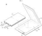
- FIGS. 1 and 2 show a secondary battery according to an embodiment of the present disclosure.
- a secondary battery 10 includes an electrode assembly 12 to which an electrode lead 11 is attached, and a case 13.
- the electrode assembly 12 includes a positive electrode plate, a negative electrode plate and a separator.
- a positive electrode plate and a negative electrode plate may be sequentially laminated with a separator being interposed therebetween.
- the positive electrode plate may include a positive electrode current collector made of a metal thin film having excellent conductivity, for example an aluminum (Al) foil, and a positive electrode active material layer coated on at least one surface thereof.
- the positive electrode plate may include a positive electrode tab made of a metal material - for example, an aluminum (Al) material, at one side end thereof. The positive electrode tab may protrude from one side end of the positive electrode plate. The positive electrode tab may be welded to one side end of the positive electrode plate, or be bonded thereto using a conductive adhesive.
- the negative electrode plate may include a negative electrode current collector made of a conductive metal thin film - for example, a copper (Cu) foil, and a negative electrode active material layer coated on at least one surface thereof.
- the negative electrode plate may include a negative electrode tab formed of a metal material, for example a nickel (Ni) material, at one side end thereof. The negative electrode tab may protrude from one side end of the negative electrode plate. The negative electrode tab may be welded to one side end of the negative electrode plate, or be bonded thereto using a conductive adhesive.
- the separator is located between the positive electrode plate and the negative electrode plate to electrically insulate the positive electrode plate and the negative electrode plate from each other.
- the separator may be a porous membrane so that lithium ions can pass between the positive electrode plate and the negative electrode plate.
- the separator may include, for example, a porous membrane using polyethylene (PE), or polypropylene (PP), or a composite film thereof.
- An inorganic coating layer may be provided on the surface of the separator.
- the inorganic coating layer may have a structure in which inorganic particles are bonded to each other by a binder to form an interstitial volume between the particles.
- the electrode assembly 12 may be a jelly-roll (winding-type) electrode assembly having a structure in which long sheet-type positive and negative electrodes are wound with a separator being interposed therebetween, a stacked (stack-type) electrode assembly having a structure in which a plurality of positive and negative electrodes cut into units of a predetermined size are sequentially stacked with a separator being interposed therebetween, a stack/folding type electrode assembly having a structure in which bi-cells or full-cells where positive and negative electrodes of a predetermined unit are stacked with a separator being interposed therebetween are wound, or the like.
- the case 13 serves to accommodate the electrode assembly 12.
- the case 13 may include an accommodation portion 13a for accommodating the electrode assembly 12, and a sealing portion 13b formed to seal the electrode assembly 12 as shown in Fig. 1 .
- the sealing portion 13b may include a sealant resin, and the sealant resin may be fused along the outer circumference of the accommodation portion 13a to seal the electrode assembly 12.
- the case 13 may be provided in a film form having a multilayer structure including an outer layer for protection against external impacts, a metal barrier layer for blocking moisture, and a sealant layer for sealing the case.
- the outer layer may include a polyester-based film using poly(ethylene terephthalate) (PET), polybutylene terephthalate, polyethylene naphthalate, polybutylene naphthalate, co-polyester, polycarbonate, nylon, or the like, and may be configured in a single layer or multiple layers.
- PET poly(ethylene terephthalate)
- PET polybutylene terephthalate
- polyethylene naphthalate polybutylene naphthalate
- co-polyester polycarbonate
- nylon nylon
- the metal barrier layer may include aluminum, copper, or the like.
- the sealant layer may contain a sealant resin and may be configured in a single layer or multiple layers.
- the sealant resin may include polypropylene (PP), acid-modified polypropylene (PPa), random polypropylene, ethylene propylene copolymer, or two or more thereof.
- the ethylene propylene copolymer may include, but is not limited to, ethylene-propylene rubber, ethylene-propylene block copolymer, and the like.
- the case 13 may be in a pouch form.
- the pouch-type battery case 13 may include an upper pouch and a lower pouch. If the case 13 includes an upper pouch and a lower pouch, after the upper pouch and the lower pouch are positioned so that the sealant resins thereof face each other, the facing sealant resins may be fused to each other by heat and pressure to have a structure that seals the battery.
- the fusion of the sealing portion 13b may be thermal fusion, ultrasonic fusion, or the like, but is not particularly limited as long as the sealing portion 13b can be fused.
- the sealing portion 13b may be sealed on four or three peripheral sides the case 13 in some embodiments.
- the boundary surface between the upper pouch and the lower pouch is bent so that the electrode assembly accommodation portions 13a formed on the upper pouch and the lower pouch overlap, and in this state, the edges of the remaining three sides are sealed except for the bending portion.
- the electrode lead 11 may be accommodated in the case 13 so that a part thereof is exposed to the outside of the case 13 as shown in FIG. 1 .
- Secondary battery 10 includes a lead film 14.
- the lead film 14 surrounds a part of the outer surface of the electrode lead 11 and the lead film 14 is interposed between the electrode lead 11 and the case 13.
- the lead film 14 may be interposed between the electrode lead 11 and a portion of the sealing portion 13b of the case 13 where the electrode lead 11 protrudes or extends away from case 13 to help the bonding of the electrode lead 11 and the case 13.
- the secondary battery 10 has a vent region (not shown) formed in at least a part of the case 13, and a vent member 15 may be inserted into the vent region.
- the vent member 15 may induce the discharge of gas in a specific direction, thereby improving the safety of the battery.
- vent member 15 and the case 13 may overlap by means of thermal fusion.
- the vent member 15 and the case 13 may be overlapped by means of an adhesive such as glue.
- the vent member 15 and the case 13 may be physically coupled to each other by means of a clip or the like.
- at least a part of the vent member 15 may be embedded in a film constituting the case 13, for example a sealant resin.
- the vent member 15 has a maximum sealing strength of less than 6 kgf/15 mm at 100°C or higher. If the vent member 15 satisfies the above-mentioned sealing strength in the above-mentioned temperature range, the sealing strength of the part of the case 13 in which the vent member 15 is inserted is lowered at 100°C or higher, so that the vent characteristic may be readily implemented.
- the vent member 15 has a maximum sealing strength of 6 kgf/15mm or more at 100° C or higher, the sealing strength of the part of the case 13 in which the vent member 15 is inserted is too strong at 100° C or higher to induce a vent at a high temperature.
- the vent member 15 has a maximum sealing strength of 6 kgf/15 mm or more at room temperature to 60°C. If the vent member 15 satisfies the above-mentioned sealing strength in the above temperature range, even if the vent member 15 is inserted, the part of the case 13 into which the vent member 15 is inserted has excellent sealing strength at room temperature to 60°C, which may easily secure the sealing property of the battery.
- vent member 15 When the vent member 15 has a maximum sealing strength of less than 6 kgf/15 mm at room temperature to 60°C, it is difficult to secure sealing properties of the part of the case 13 into which the vent member 15 is inserted at room temperature to 60° C.
- the vent member 15 may have a maximum sealing strength of less than 5 kgf/15mm or less than 4.5 kgf/15mm at 100°C or higher. In an embodiment of the present disclosure, the vent member 15 may have a maximum sealing strength of less than 6 kgf/15 mm or less than 5 kgf/15mm or less than 4.5 kgf/15mm at 100°C to 120°C. In an embodiment of the present disclosure, the vent member 15 may have a maximum sealing strength of less than 3 kgf/15 mm or less than 2 kgf/15 mm or less than 1 kgf/15 mm or less than 0.5 kgf/15 mm at 120°C or higher.
- the sealing strength of the part of the case 13 in which the vent member 15 is inserted may be lowered at 100°C or higher, so that the vent characteristic may be readily implemented.
- the vent member 15 may have a maximum sealing strength of 8 kgf/15 mm or more or 10 kgf/15 mm or more at room temperature to 60°C. If the vent member 15 satisfies the above-mentioned sealing strength in the above temperature range, even if the vent member 15 is inserted, the part of the case 13 in which the vent member 15 is inserted may have excellent sealing strength at room temperature to 60°C, which may easily secure the sealing property of the battery.
- the vent member 15 may have an average sealing strength of less than 4.5 kgf/15 mm or less than 3 kgf/15 mm at 100°C or above. In an embodiment of the present disclosure, the vent member 15 may have an average sealing strength of less than 4.5 kgf/15 mm or less than 3 kgf/15 mm at 100°C to 120°C. In an embodiment of the present disclosure, the vent member 15 may have an average sealing strength of less than 2 kgf/15 mm or less than 1 kgf/15 mm or less than 0.5 kgf/15 mm at 120°C or higher.
- the sealing strength of the part of the case 13 in which the vent member 15 is inserted may be lowered at 100°C or above, so that the vent characteristic may be implemented more easily.
- the vent member 15 may have an average sealing strength of 4.5 kgf/15 mm or more or 5 kgf/15 mm or more or 6 kgf/15mm or more or 7 kgf/15 mm or more at room temperature to 60°C. If the vent member 15 satisfies the above-mentioned sealing strength in the above temperature range, even if the vent member 15 is inserted, the part of the case 13 in which the vent member 15 is inserted may have excellent sealing strength at room temperature to 60°C, thereby easily securing the sealing property.
- the vent member 15 may have an average sealing strength of less than 4.5 kgf/15 mm at 100°C or above.
- the vent member 15 may have an average sealing strength of 4.5 kgf/15 mm or more at room temperature to 60°C. If the vent member 15 has the above-mentioned sealing strength in the above-described temperature range, the sealing strength of the part of the case 13 in which the vent member 15 is inserted may be lowered at 100°C or above, so that the vent characteristic may be easily implemented. In addition, since the case 13 has excellent sealing strength at room temperature to 60°C, the sealing property of the battery may be easily secured.
- the sealing strength of the vent member 15 according to temperature may be measured by conducting a tensile test at a speed of 5 mm/min, after cutting the part of the case 13 in which the vent member 15 is inserted into a width of 15 mm and a length of 5 cm and then biting both ends thereof using a UTM jig in a state where both ends are spread to 180°.
- the maximum sealing strength means a maximum value when the case 13 is broken
- the average sealing strength means an average value when the case 13 is stretched by 8 mm at 4.5 kgf/15 mm when the maximum sealing strength is 4.5 kgf/15 mm or more and an average value when the case 13 is stretched by 8 mm at the maximum sealing strength when the maximum sealing strength is less than 4.5 kgf/15 mm.
- FIG. 3 is a diagram showing a state in which a vent occurs in the secondary battery according to an embodiment of the present invention. Specifically, FIG. 3 is a cross-sectional view showing the vent member in the secondary battery according to an embodiment of the present invention.
- the vent member has an excellent sealing strength so that the vent region where the vent member is inserted serves to seal the case from the outside. If the temperature of the battery is excessively increased due to abnormal operation of the battery, for example if the temperature of the battery becomes 100°C or above, as the sealing strength of the vent member is lowered, the sealing strength of the portion into which the vent member is inserted is reduced, so that the vent may be guided to this portion. For example, as the pressure of the gas inside the battery is applied to the interface between the vent member and the case so that a gap is formed between the vent member and the case, the vent may be guided thereto.
- the vent member 15 may be vented at 100°C to 120°C to expel or exhaust gases from the accommodation portion to outside the secondary battery.
- the vent member 15 may be vented at 100°C to 120°C with a pressure of 1.5 atm or more.
- the vent member 15 is vented in the above-described temperature range and/or the above-mentioned pressure condition, it is easier to seal the battery during normal operation of the battery and to induce gas discharge only during abnormal operation of the battery.
- the vent member contains linear low-density polyethylene having a poly dispersity index (PDI) of 4 or less. If the poly dispersity index of the linear low-density polyethylene satisfies the above range, the molecular weight distribution is narrow, so the sealing strength and properties may be excellent during normal operation of the battery, for example at room temperature to 60°C.
- PDI poly dispersity index
- the linear low-density polyethylene may have a poly dispersity index (PDI) of 3.8 or less, or 3.796 or less, or 3.5 or less, or 3.023 or less, or 3 or less, or 2.7 or less, or 2.674 or less.
- the poly dispersity index (PDI) may be 1.0 or more. If the poly dispersity index of the linear low-density polyethylene satisfies the above range, the molecular weight distribution is narrow, so the sealing strength and properties may be more excellent during normal operation of the battery.
- the linear low-density polyethylene may have a weight-average molecular weight of 100,000 g/mol to 400,000 g/mol, or 200,000 g/mol to 350,000 g/mol, or 230,000 g/mol to 300,000 g/mol. If the weight-average molecular weight of the linear low-density polyethylene satisfies the above-described range, the sealing strength of the vent member may be improved during normal operation of the battery. For example, this may allow the vent member to more easily have a maximum sealing strength of 6 kgf/15 mm or more at room temperature to 60°C.
- the weight-average molecular weight and the poly dispersity index of the linear low-density polyethylene may be measured by gel permeation chromatography (GPC) under the following conditions.
- the linear low-density polyethylene may have a lower melting point than the sealant resin. If the linear low-density polyethylene has a lower melting point than the sealant resin, the vent member may be melted faster than the sealant resin at high temperature. Accordingly, the sealing strength of the portion where the vent member 15 is inserted may be further lowered compared to the sealing strength of the case portion containing the sealant resin at high temperature, so that the venting characteristic may be readily implemented.
- the linear low-density polyethylene may have a melting point of 100°C to 130°C, or 105°C to 125°C, or 110°C to 120°C. If the melting point of the linear low-density polyethylene satisfies the above-mentioned range, the sealing strength of the case 13 in which the vent member 15 is inserted may be lowered at a high temperature, for example 100°C or higher, so that the venting characteristic may be readily implemented. In addition, this may allow the vent member to more easily have a maximum sealing strength of less than 6 kgf/15 mm at 100°C or higher and a maximum sealing strength of 6 kgf/15 mm or more at room temperature to 60°C.
- the melting point of the linear low-density polyethylene may be measured using a differential scanning calorimeter (DSC). For example, the temperature of a sample is increased from 30°C to 280°C at 10°C/min, maintained at 280°C for 10 minutes, cooled to 30°C at 10°C/min, and then maintained at 30°C for 10 minutes. Then, after increasing the temperature of the sample from 30°C to 280°C at 10°C/min, the melting point may be measured by maintaining the temperature at 280°C for 10 minutes.
- DSC differential scanning calorimeter
- the linear low-density polyethylene may be polymerized in the presence of a metallocene catalyst. If the linear low-density polyethylene is polymerized in the presence of a metallocene catalyst, it may be more advantageous in terms of sealing strength and properties, compared to the case where it is polymerized in the presence of a Ziegler-Natta catalyst. For example, this may allow the vent member containing linear low-density polyethylene to more easily have a maximum sealing strength of less than 6 kgf/15 mm at 100°C or higher and a maximum sealing strength of 6 kgf/15 mm or more at room temperature to 60°C.
- the crystallization temperature of the sealant resin and the crystallization temperature of the linear low-density polyethylene may be similar.
- the difference between the crystallization temperature of the sealant resin and the crystallization temperature of the linear low-density polyethylene may be 10°C or less, or 5°C or less.
- the difference between the crystallization temperature of the sealant resin and the crystallization temperature of the linear low-density polyethylene may be 0.1°C or more.
- the sealant resin and the linear low-density polyethylene may have more excellent fusion characteristic during normal operation of the battery. For example, this may allow the vent member containing linear low-density polyethylene to more easily have a maximum sealing strength of 6 kgf/15 mm or more at room temperature to 60°C.
- the linear low-density polyethylene may have a crystallization temperature of 90°C to 115°C, or 95°C to 110°C, or 100°C to 110°C, or 105°C to 110°C. If the crystallization temperature of the linear low-density polyethylene satisfies the above range, the sealant resin and the linear low-density polyethylene may have improved fusion characteristics.
- the difference between the crystallization temperature of the sealant resin and the crystallization temperature of the linear low-density polyethylene may be 10°C or less, and the linear low-density polyethylene may have a crystallization temperature of 90°C to 115°C.
- the crystallization temperature may be measured using a differential scanning calorimeter (DSC). For example, the temperature of the sample may be increased from 30°C to 280°C at 10°C/min, maintained at 280°C for 10 minutes, cooled to 30°C at 10°C/min, and then maintained at 30°C for 10 minutes. Then, after increasing the temperature of the sample from 30°C to 280°C at 10°C/min, the crystallization temperature may be measured by maintaining the temperature at 280°C for 10 minutes.
- DSC differential scanning calorimeter
- the vent member 15 may have various shapes so that gas is easily directed toward the vent region.
- the vent member 15 may have a film shape.
- the vent member 15 may be formed to have a predetermined thickness of a preset size.
- the vent member(15) may be located in a sealing portion.
- the vent member 15 may be located in the sealing portion at a corner side of the case.
- the vent member 15 may be located at a corner side of the sealing portion where the electrode lead 11 is exposed to the outside.
- the vent member 15 may be located at the sealing portion beside the electrode leads 11, except for a region between the electrode leads 11. If the vent member 15 is located at the corner side of the sealing portion where the electrode lead 11 is exposed to the outside, the amount of gas vented toward the electrode lead 11 may be minimized, thereby further enhancing the safety of the battery.
- the sealing portion 13b is sealed on three sides, the bent side of the case and one end of the vent member 15 may be in close contact.
- the vent member 15 may be inserted into the case 13 so that its insertion length may be varied, or its venting pressure and position may be controlled depending on the design requirements.
- the insertion length of the vent member means a maximum value of the distance between one end and the other end of the vent member based on the protruding direction of the electrode lead.
- the insertion length of the vent member 15 may be smaller than the width of the sealing portion 13b.
- the insertion length of the vent member 15 may be less than about 50% of the width of the sealing portion 13b.
- the width of the sealing portion 13b means a maximum value of the distance between one end and the other end of the sealing portion 13b based on the protruding direction of the electrode lead 11.
- the insertion length of the vent member 15 may be greater than the width of the sealing portion 13b.
- the vent member 15 may be inserted to be exposed out of the case 13 through the accommodation portion 13a.
- the vent member 15 may further include an adhesive layer for improved placement.
- FIG. 6 is a plan view showing a secondary battery according to another embodiment of the present disclosure.
- the vent member 15 may be located in the sealing portion excluding a sealing portion where the electrode lead 11 is exposed to the outside.
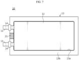
- Fig. 7 is a plan view showing a secondary battery according to another embodiment of the present disclosure.
- the vent member 15 may be located in the sealing portion where the electrode lead 11 is exposed to the outside.
- the vent member 15 may be located in the sealing portion between the electrode lead 11 and the electrode lead 11.
- the secondary battery according to an embodiment of the present disclosure includes the vent member containing linear low-density polyethylene having a poly dispersity index (PDI) of 4 or less, and the vent member has a maximum sealing strength of less than 6 kgf/15 mm at 100°C or above and a maximum sealing strength of 6 kgf/15 mm or more at room temperature to 60°C, directional venting for discharging gas in a specific direction by lowering the sealing strength at high temperature may be implemented more conveniently and efficiently, thereby minimize damage to the electrode caused by gas when thermal propagation occurs - i . e ., when the internal temperature of the secondary battery rise.
- PDI poly dispersity index
- the secondary battery may be a cylindrical, prismatic, or pouch-type secondary battery.
- the secondary battery may be a pouch-type secondary battery.
- vent member containing linear low-density polyethylene (ExxonMobile, Exceed TM , 1018) having a comonomer with a carbon number of 6 polymerized in the presence of a metallocene catalyst was inserted between the polypropylene resins and then thermally fused, thereby manufacturing a secondary battery.
- a secondary battery was manufactured in the same manner as in Example 1, except that the vent member containing linear low-density polyethylene (LG Chem, Lucene TM , SP311) having a comonomer with a carbon number of 6 polymerized in the presence of a metallocene catalyst was inserted between the polypropylene resins.
- LG Chem, Lucene TM , SP311 linear low-density polyethylene having a comonomer with a carbon number of 6 polymerized in the presence of a metallocene catalyst was inserted between the polypropylene resins.
- a secondary battery was manufactured in the same manner as in Example 1, except that the vent member containing linear low-density polyethylene (Dow, Elite TM , 5401GT) having a comonomer with a carbon number of 8 polymerized in the presence of a metallocene catalyst was inserted between polypropylene resins.
- the vent member containing linear low-density polyethylene (Dow, Elite TM , 5401GT) having a comonomer with a carbon number of 8 polymerized in the presence of a metallocene catalyst was inserted between polypropylene resins.
- a secondary battery was manufactured in the same manner as in Example 1, except that the vent member containing linear low-density polyethylene having a comonomer with a carbon number of 4 polymerized in the presence of a Ziegler-Natta catalyst was inserted between polypropylene resins.
- a secondary battery was manufactured in the same manner as in Example 1, except that the vent member containing high-density polyethylene (SABIC ® , HDPE F04660) was inserted between the polypropylene resins.
- SABIC ® high-density polyethylene
- a secondary battery was manufactured in the same manner as in Example 1, except that the vent member containing linear low-density polyethylene (Dowlex TM 2645G) having a comonomer with a carbon number of 6 polymerized in the presence of a Ziegler-Natta catalyst was inserted between polypropylene resins.
- the vent member containing linear low-density polyethylene (Dowlex TM 2645G) having a comonomer with a carbon number of 6 polymerized in the presence of a Ziegler-Natta catalyst was inserted between polypropylene resins.
- a secondary battery was manufactured in the same manner as in Example 1, except that the vent member containing linear low-density polyethylene (Dowlex TM 2045G) having a comonomer with a carbon number of 8 polymerized in the presence of a Ziegler-Natta catalyst was inserted between polypropylene resins.
- the vent member containing linear low-density polyethylene (Dowlex TM 2045G) having a comonomer with a carbon number of 8 polymerized in the presence of a Ziegler-Natta catalyst was inserted between polypropylene resins.
- a secondary battery was manufactured in the same manner as in Example 1, except that the vent member containing linear low-density polyethylene (LG Chem, Lucene TM , LF100) having a comonomer with a carbon number of 8 polymerized in the presence of a metallocene catalyst was inserted between polypropylene resins.
- LG Chem, Lucene TM , LF100 linear low-density polyethylene
- Evaluation Example 1 Evaluation of physical properties of the resin used in the vent member
- the melting points, the comonomer contents, the weight-average molecular weights, the poly dispersity indexes, and the crystallization temperatures of the resins used in the vent members (also referred herein as ⁇ vent resin') of Examples 1 to 3 and Comparative Example 2, 4 to 6 and the sealant resin used in Comparative Example 1 were measured, as shown in Table 1 below.
- the melting points and the crystallization temperatures of the sealant resin used in Comparative Example 1 and the vent resins used in the vent members of Examples 1 to 3 and Comparative Example 2, 4 to 6 were measured as follows.
- the temperature of the sample was increased from 30°C to 280°C at 10°C/min using a differential scanning calorimeter (DSC), maintained at 280°C for 10 minutes, cooled to 30°C at 10°C/min, and then maintained at 30°C for 10 minutes. Thereafter, after increasing the temperature of the sample from 30°C to 280°C at 10°C/min, the melting point and the crystallization temperature were measured by maintaining the temperature at 280°C for 10 minutes.
- DSC differential scanning calorimeter
- the weight-average molecular weights and the poly dispersity indexes of the sealant resin used in Comparative Example 1 and the vent resins used in the vent members of Examples 1 to 3 and Comparative Example 2, 4 to 6 were measured using gel permeation chromatography (GPC) under the following conditions.
- the maximum sealing strength means a maximum value when the case is broken
- the average sealing strength means an average value when the case is stretched by 8 mm at 4.5 kgf/15 mm when the maximum sealing strength is 4.5 kgf/15 mm or more and an average value when the case is stretched by 8 mm at the maximum sealing strength when the maximum sealing strength is less than 4.5 kgf/15 mm.
- Table 2 Example 1
- Example 2 Example 3 Com. Ex. 1 Com. Ex. 2 Max. Ave. Max. Ave. Max. Ave. Max. Ave. Max. Ave. Max. Ave. Sealing strength (kgf/15 mm) Room temp.
- the part of the case in which the vent member is inserted had a maximum sealing strength of 6.0 kgf/15 mm or more and an average sealing strength of 4.5 kgf/15 mm or more at room temperature to 60°C, and had a maximum sealing strength of less than 6.0 kgf/15 mm and an average sealing strength of less than 4.5 kgf/15 mm at 100°C or above.
- the secondary battery having the vent member manufactured in Examples 1 to 3 may ensure proper sealing strength at room temperature to 60°C at which the battery normally operates, and may discharge gas through the vent member having a weakened sealing strength when the battery is heated to high temperature of 100°C or above due to an abnormal phenomenon.
- the secondary battery manufactured in Comparative Example 1 may secure proper sealing strength at room temperature to 60°C at which the battery normally operates. However, when the battery is heated to high temperature of 100°C or above due to an abnormal phenomenon, gas is discharged in unspecified directions, which would cause ignition of the battery.
- the part of the case in which the vent member is inserted had a maximum sealing strength of less than 6.0 kgf/15 mm and an average sealing strength of less than 4.5 kgf/15 mm at room temperature to 60°C. At a temperature of 100°C or above, the sealing strength was too low to be measured. From this, it was determined that the secondary batteries manufactured in Comparative Examples 2 to 6 cannot secure proper sealing strength strength at room temperature to 60°C at which the battery normally operates.
Landscapes
- Chemical & Material Sciences (AREA)
- Chemical Kinetics & Catalysis (AREA)
- Electrochemistry (AREA)
- General Chemical & Material Sciences (AREA)
- Health & Medical Sciences (AREA)
- Medicinal Chemistry (AREA)
- Polymers & Plastics (AREA)
- Organic Chemistry (AREA)
- Sealing Battery Cases Or Jackets (AREA)
- Gas Exhaust Devices For Batteries (AREA)
- Addition Polymer Or Copolymer, Post-Treatments, Or Chemical Modifications (AREA)
Abstract
Description
- The present application claims priority to
Korean Patent Application No. 10-2021-0049378 filed on April 15, 2021 Korean Patent Application No. 10-2021-0150951 filed on November 4, 2021 - The present disclosure relates to a secondary battery, and more particularly, to a secondary battery having a vent member.
- Secondary batteries are highly applicable to various products and exhibit superior electrical properties such as high energy density, etc. Secondary batteries are commonly used not only in portable devices but also in electric vehicles (EVs) or hybrid electric vehicles (HEVs) driven by electrical power sources. The secondary battery is drawing attentions as a new energy source for enhancing environment friendliness and energy efficiency in that the use of fossil fuels can be reduced greatly and no byproduct is generated during energy consumption.
- Secondary batteries widely used at present include lithium ion batteries, lithium polymer batteries, nickel cadmium batteries, nickel hydrogen batteries, nickel zinc batteries and the like.
- The secondary battery generally has a structure in which an electrode assembly including at least one unit cell having a positive electrode/separator/negative electrode structure is accommodated in a case of a laminate sheet in which an outer layer, a metal barrier layer and a sealant layer are sequentially laminated, and a sealant resin of the sealant layer is fused to seal the electrode assembly.
- In the conventional secondary battery, the battery may ignite due to various causes such as a short circuit inside the secondary battery, overcharge or overdischarge, temperature control, or the like. At this time, thermal propagation where the temperature inside the secondary battery rises rapidly and simultaneously the heat is transferred to neighboring battery cells may be generated, which may further increase the fire.
- In order to minimize damage to the secondary battery caused by gas generated by thermal propagation which is generated when the internal temperature of the secondary battery rises rapidly, the directional venting characteristic is required to discharge the gas in one direction. However, the conventional secondary battery has a problem in that it is difficult to induce gas discharge in a specific direction.
- Therefore, the present disclosure is directed to providing a secondary battery with improved safety by inducing gas discharge in a specific direction.
- Disclosed herein are secondary batteries with a vent member.
- In accordance with an aspect of the present disclosure, there is provided a secondary battery. The secondary battery may include an electrode assembly; an electrode lead attached to the electrode assembly; a case configured to receive the electrode assembly therein; a lead film configured to surround a part of an outer surface of the electrode lead and interposed between the electrode lead and the case; a vent region formed in at least a part of the case; and a vent member inserted into the vent region and configured to contain linear low-density polyethylene having a poly dispersity index (PDI) of 4 or less. The vent member has a maximum sealing strength of less than 6 kgf/15 mm at 100°C or above and a maximum sealing strength of 6 kgf/15 mm or more at room temperature to 60°C.
- Continuing in accordance with this aspect, the vent member may have an average sealing strength of less than 4.5 kgf/15 mm at 100°C or above.
- Continuing in accordance with this aspect, the vent member may have an average sealing strength of 4.5 kgf/15 mm or more at room temperature to 60°C.
- Continuing in accordance with this aspect, the case may include a sealing portion formed to seal the electrode assembly. The sealing portion may contain a sealant resin. The vent member containing the linear low-density polyethylene having a comonomer with a carbon number of 6 or more may have a lower melting point than the sealant resin.
- Continuing in accordance with this aspect, the vent member may melt at 100°C to 120°C to vent gases.
- Continuing in accordance with this aspect, the vent member may be vented at a pressure of 1.5 atm or more.
- Continuing in accordance with this aspect, the linear low-density polyethylene may be polymerized in the presence of a metallocene catalyst.
- Continuing in accordance with this aspect, a difference between a crystallization temperature of the sealant resin and a crystallization temperature of the linear low-density polyethylene may be 10°C or less.
- Continuing in accordance with this aspect, the linear low-density polyethylene may have a crystallization temperature of 90°C to 115°C.
- Continuing in accordance with this aspect, the linear low-density polyethylene may have a melting point of 100°C to 130°C.
- Continuing in accordance with this aspect, the linear low-density polyethylene may have a weight-average molecular weight of 100,000 g/mol to 400,000 g/mol.
- Continuing in accordance with this aspect, the vent region may be located in the sealing portion.
- Continuing in accordance with this aspect, the vent region may be located in the sealing portion at a corner of the case.
- Continuing in accordance with this aspect, the secondary battery may be a pouch-type secondary battery.
- Continuing in accordance with this aspect, the vent member may have a maximum sealing strength of less than 6 kgf/15 mm at 100°C to 120°C.
- Continuing in accordance with this aspect, the vent member may have an average sealing strength of less than 4.5 kgf/15 mm at 100°C to 120°C.
- Continuing in accordance with this aspect, the linear low-density polyethylene may have a poly dispersity index (PDI) of from 1 and more to less than 4.
- Continuing in accordance with this aspect, the vent member may have a maximum sealing strength of less than 3 kgf/15 mm at 120°C or more.
- Continuing in accordance with this aspect, the vent member may have an average sealing strength of less than 2 kgf/15 mm at 120°C or more.
- A secondary battery according to an embodiment of the present disclosure may include the vent member having a maximum sealing strength of less than 6 kgf/15 mm at 100°C or above and a maximum sealing strength of 6 kgf/15 mm or more at room temperature to 60°C. Accordingly, it is possible to secure the sealing property of the battery at room temperature to 60°C and induce gas discharge toward the vent region at 100°C or above. Accordingly, the safety of the battery is improved.
- A secondary battery according to an embodiment of the present disclosure may include a vent member containing linear low-density polyethylene having a poly dispersity index (PDI) of 4 or less. Accordingly, it is possible to secure the sealing property of the battery at the normal operation temperature of the battery.
- The accompanying drawings illustrate a preferred embodiment of the present disclosure and together with the foregoing disclosure, serve to provide further understanding of the technical features of the present disclosure, and thus, the present disclosure is not construed as being limited to the drawing.
-
FIG. 1 is an exploded perspective view showing a secondary battery according to an embodiment of the present disclosure. -
FIG. 2 is a plan view showing the secondary battery according to an embodiment of the present disclosure. -
FIG. 3 is a diagram showing a state in which a vent occurs in the secondary battery according to an embodiment of the present disclosure. -
FIG. 4 is a plan view showing a secondary battery according to another embodiment of the present disclosure. -
Fig. 5 is a plan view showing a secondary battery according to another embodiment of the present disclosure. -
Fig. 6 is a plan view showing a secondary battery according to another embodiment of the present disclosure. -
Fig. 7 is a plan view showing a secondary battery according to another embodiment of the present disclosure. - Hereinafter, preferred embodiments of the present disclosure will be described in detail with reference to the accompanying drawings. Prior to the description, it should be understood that the terms used in the specification and the appended claims should not be construed as limited to general and dictionary meanings, but interpreted based on the meanings and concepts corresponding to technical aspects of the present disclosure on the basis of the principle that the inventor is allowed to define terms appropriately for the best explanation.
- Therefore, the description proposed herein is just a preferable example for the purpose of illustrations only, not intended to limit the scope of the disclosure, so it should be understood that other equivalents and modifications could be made thereto without departing from the scope of the disclosure.
- In general, the battery operates normally below 100°C, especially at room temperature to 60°C or below. However, if an abnormal reaction occurs, the temperature of the battery may rise. If the temperature of the battery rises, problems such as gas generation inside the battery occur. In particular, if the temperature of the battery becomes 100°C or higher, the battery swells more seriously due to the gas generated inside the battery.
- The inventors have completed the invention by designing a battery capable of securing the sealing property of the battery at the normal operation temperature of the battery and inducing a vent at a high temperature.
- A secondary battery according to one aspect of the present disclosure includes an electrode assembly to which an electrode lead is attached; a case configured to accommodate the electrode assembly; a lead film configured to surround a part of an outer surface of the electrode lead and interposed between the electrode lead and the case; a vent region formed in at least a part of the case; and a vent member inserted into the vent region and configured to contain linear low-density polyethylene having a poly dispersity index (PDI) of 4 or less, wherein the vent member has a maximum sealing strength of less than 6 kgf/15 mm at 100°C or above and a maximum sealing strength of 6 kgf/15 mm or more at room temperature to 60°C.
-
FIGS. 1 and2 show a secondary battery according to an embodiment of the present disclosure. - A
secondary battery 10 includes anelectrode assembly 12 to which anelectrode lead 11 is attached, and acase 13. - The
electrode assembly 12 includes a positive electrode plate, a negative electrode plate and a separator. In theelectrode assembly 12, a positive electrode plate and a negative electrode plate may be sequentially laminated with a separator being interposed therebetween. - The positive electrode plate may include a positive electrode current collector made of a metal thin film having excellent conductivity, for example an aluminum (Al) foil, and a positive electrode active material layer coated on at least one surface thereof. In addition, the positive electrode plate may include a positive electrode tab made of a metal material - for example, an aluminum (Al) material, at one side end thereof. The positive electrode tab may protrude from one side end of the positive electrode plate. The positive electrode tab may be welded to one side end of the positive electrode plate, or be bonded thereto using a conductive adhesive.
- The negative electrode plate may include a negative electrode current collector made of a conductive metal thin film - for example, a copper (Cu) foil, and a negative electrode active material layer coated on at least one surface thereof. In addition, the negative electrode plate may include a negative electrode tab formed of a metal material, for example a nickel (Ni) material, at one side end thereof. The negative electrode tab may protrude from one side end of the negative electrode plate. The negative electrode tab may be welded to one side end of the negative electrode plate, or be bonded thereto using a conductive adhesive.
- The separator is located between the positive electrode plate and the negative electrode plate to electrically insulate the positive electrode plate and the negative electrode plate from each other. The separator may be a porous membrane so that lithium ions can pass between the positive electrode plate and the negative electrode plate. The separator may include, for example, a porous membrane using polyethylene (PE), or polypropylene (PP), or a composite film thereof.
- An inorganic coating layer may be provided on the surface of the separator. The inorganic coating layer may have a structure in which inorganic particles are bonded to each other by a binder to form an interstitial volume between the particles.
- The
electrode assembly 12 may be a jelly-roll (winding-type) electrode assembly having a structure in which long sheet-type positive and negative electrodes are wound with a separator being interposed therebetween, a stacked (stack-type) electrode assembly having a structure in which a plurality of positive and negative electrodes cut into units of a predetermined size are sequentially stacked with a separator being interposed therebetween, a stack/folding type electrode assembly having a structure in which bi-cells or full-cells where positive and negative electrodes of a predetermined unit are stacked with a separator being interposed therebetween are wound, or the like. - The
case 13 serves to accommodate theelectrode assembly 12. - In an embodiment of the present disclosure, the
case 13 may include anaccommodation portion 13a for accommodating theelectrode assembly 12, and a sealingportion 13b formed to seal theelectrode assembly 12 as shown inFig. 1 . - The sealing
portion 13b may include a sealant resin, and the sealant resin may be fused along the outer circumference of theaccommodation portion 13a to seal theelectrode assembly 12. - In an embodiment of the present disclosure, the
case 13 may be provided in a film form having a multilayer structure including an outer layer for protection against external impacts, a metal barrier layer for blocking moisture, and a sealant layer for sealing the case. - The outer layer may include a polyester-based film using poly(ethylene terephthalate) (PET), polybutylene terephthalate, polyethylene naphthalate, polybutylene naphthalate, co-polyester, polycarbonate, nylon, or the like, and may be configured in a single layer or multiple layers.
- The metal barrier layer may include aluminum, copper, or the like.
- The sealant layer may contain a sealant resin and may be configured in a single layer or multiple layers.
- The sealant resin may include polypropylene (PP), acid-modified polypropylene (PPa), random polypropylene, ethylene propylene copolymer, or two or more thereof. The ethylene propylene copolymer may include, but is not limited to, ethylene-propylene rubber, ethylene-propylene block copolymer, and the like.
- In an embodiment of the present disclosure, the
case 13 may be in a pouch form. - The pouch-
type battery case 13 may include an upper pouch and a lower pouch. If thecase 13 includes an upper pouch and a lower pouch, after the upper pouch and the lower pouch are positioned so that the sealant resins thereof face each other, the facing sealant resins may be fused to each other by heat and pressure to have a structure that seals the battery. - The fusion of the sealing
portion 13b may be thermal fusion, ultrasonic fusion, or the like, but is not particularly limited as long as the sealingportion 13b can be fused. - The sealing
portion 13b may be sealed on four or three peripheral sides thecase 13 in some embodiments. In the three-sided sealing structure, after the upper pouch and the lower pouch are formed on one pouch sheet, the boundary surface between the upper pouch and the lower pouch is bent so that the electrodeassembly accommodation portions 13a formed on the upper pouch and the lower pouch overlap, and in this state, the edges of the remaining three sides are sealed except for the bending portion. - The
electrode lead 11 may be accommodated in thecase 13 so that a part thereof is exposed to the outside of thecase 13 as shown inFIG. 1 . -
Secondary battery 10 according to an embodiment of the present disclosure includes alead film 14. Thelead film 14 surrounds a part of the outer surface of theelectrode lead 11 and thelead film 14 is interposed between theelectrode lead 11 and thecase 13. For example, thelead film 14 may be interposed between theelectrode lead 11 and a portion of the sealingportion 13b of thecase 13 where theelectrode lead 11 protrudes or extends away fromcase 13 to help the bonding of theelectrode lead 11 and thecase 13. - Referring to
FIGS. 1 and2 , thesecondary battery 10 according to an embodiment of the present disclosure has a vent region (not shown) formed in at least a part of thecase 13, and avent member 15 may be inserted into the vent region. When thermal propagation occurs, thevent member 15 may induce the discharge of gas in a specific direction, thereby improving the safety of the battery. - The
vent member 15 and thecase 13 may overlap by means of thermal fusion. In another example, thevent member 15 and thecase 13 may be overlapped by means of an adhesive such as glue. In another example, thevent member 15 and thecase 13 may be physically coupled to each other by means of a clip or the like. In another example, at least a part of thevent member 15 may be embedded in a film constituting thecase 13, for example a sealant resin. - The
vent member 15 has a maximum sealing strength of less than 6 kgf/15 mm at 100°C or higher. If thevent member 15 satisfies the above-mentioned sealing strength in the above-mentioned temperature range, the sealing strength of the part of thecase 13 in which thevent member 15 is inserted is lowered at 100°C or higher, so that the vent characteristic may be readily implemented. - When the
vent member 15 has a maximum sealing strength of 6 kgf/15mm or more at 100° C or higher, the sealing strength of the part of thecase 13 in which thevent member 15 is inserted is too strong at 100° C or higher to induce a vent at a high temperature. - The
vent member 15 has a maximum sealing strength of 6 kgf/15 mm or more at room temperature to 60°C. If thevent member 15 satisfies the above-mentioned sealing strength in the above temperature range, even if thevent member 15 is inserted, the part of thecase 13 into which thevent member 15 is inserted has excellent sealing strength at room temperature to 60°C, which may easily secure the sealing property of the battery. - When the
vent member 15 has a maximum sealing strength of less than 6 kgf/15 mm at room temperature to 60°C, it is difficult to secure sealing properties of the part of thecase 13 into which thevent member 15 is inserted at room temperature to 60° C. - In an embodiment of the present disclosure, the
vent member 15 may have a maximum sealing strength of less than 5 kgf/15mm or less than 4.5 kgf/15mm at 100°C or higher. In an embodiment of the present disclosure, thevent member 15 may have a maximum sealing strength of less than 6 kgf/15 mm or less than 5 kgf/15mm or less than 4.5 kgf/15mm at 100°C to 120°C. In an embodiment of the present disclosure, thevent member 15 may have a maximum sealing strength of less than 3 kgf/15 mm or less than 2 kgf/15 mm or less than 1 kgf/15 mm or less than 0.5 kgf/15 mm at 120°C or higher. If thevent member 15 satisfies the above-mentioned sealing strength in the above-mentioned temperature range, the sealing strength of the part of thecase 13 in which thevent member 15 is inserted may be lowered at 100°C or higher, so that the vent characteristic may be readily implemented. - In an embodiment of the present disclosure, the
vent member 15 may have a maximum sealing strength of 8 kgf/15 mm or more or 10 kgf/15 mm or more at room temperature to 60°C. If thevent member 15 satisfies the above-mentioned sealing strength in the above temperature range, even if thevent member 15 is inserted, the part of thecase 13 in which thevent member 15 is inserted may have excellent sealing strength at room temperature to 60°C, which may easily secure the sealing property of the battery. - In an embodiment of the present disclosure, the
vent member 15 may have an average sealing strength of less than 4.5 kgf/15 mm or less than 3 kgf/15 mm at 100°C or above. In an embodiment of the present disclosure, thevent member 15 may have an average sealing strength of less than 4.5 kgf/15 mm or less than 3 kgf/15 mm at 100°C to 120°C. In an embodiment of the present disclosure, thevent member 15 may have an average sealing strength of less than 2 kgf/15 mm or less than 1 kgf/15 mm or less than 0.5 kgf/15 mm at 120°C or higher. If thevent member 15 satisfies the above-mentioned sealing strength in the above-mentioned temperature range, the sealing strength of the part of thecase 13 in which thevent member 15 is inserted may be lowered at 100°C or above, so that the vent characteristic may be implemented more easily. - In an embodiment of the present disclosure, the
vent member 15 may have an average sealing strength of 4.5 kgf/15 mm or more or 5 kgf/15 mm or more or 6 kgf/15mm or more or 7 kgf/15 mm or more at room temperature to 60°C. If thevent member 15 satisfies the above-mentioned sealing strength in the above temperature range, even if thevent member 15 is inserted, the part of thecase 13 in which thevent member 15 is inserted may have excellent sealing strength at room temperature to 60°C, thereby easily securing the sealing property. - In an embodiment of the present disclosure, the
vent member 15 may have an average sealing strength of less than 4.5 kgf/15 mm at 100°C or above. Thevent member 15 may have an average sealing strength of 4.5 kgf/15 mm or more at room temperature to 60°C. If thevent member 15 has the above-mentioned sealing strength in the above-described temperature range, the sealing strength of the part of thecase 13 in which thevent member 15 is inserted may be lowered at 100°C or above, so that the vent characteristic may be easily implemented. In addition, since thecase 13 has excellent sealing strength at room temperature to 60°C, the sealing property of the battery may be easily secured. - The sealing strength of the
vent member 15 according to temperature may be measured by conducting a tensile test at a speed of 5 mm/min, after cutting the part of thecase 13 in which thevent member 15 is inserted into a width of 15 mm and a length of 5 cm and then biting both ends thereof using a UTM jig in a state where both ends are spread to 180°. - At this time, the maximum sealing strength means a maximum value when the
case 13 is broken, and the average sealing strength means an average value when thecase 13 is stretched by 8 mm at 4.5 kgf/15 mm when the maximum sealing strength is 4.5 kgf/15 mm or more and an average value when thecase 13 is stretched by 8 mm at the maximum sealing strength when the maximum sealing strength is less than 4.5 kgf/15 mm. -
FIG. 3 is a diagram showing a state in which a vent occurs in the secondary battery according to an embodiment of the present invention. Specifically,FIG. 3 is a cross-sectional view showing the vent member in the secondary battery according to an embodiment of the present invention. - Referring to
FIG. 3 , at a temperature at which the battery normally operates, for example at room temperature to 60°C, the vent member has an excellent sealing strength so that the vent region where the vent member is inserted serves to seal the case from the outside. If the temperature of the battery is excessively increased due to abnormal operation of the battery, for example if the temperature of the battery becomes 100°C or above, as the sealing strength of the vent member is lowered, the sealing strength of the portion into which the vent member is inserted is reduced, so that the vent may be guided to this portion. For example, as the pressure of the gas inside the battery is applied to the interface between the vent member and the case so that a gap is formed between the vent member and the case, the vent may be guided thereto. - In an embodiment of the present disclosure, the
vent member 15 may be vented at 100°C to 120°C to expel or exhaust gases from the accommodation portion to outside the secondary battery. In particular, thevent member 15 may be vented at 100°C to 120°C with a pressure of 1.5 atm or more. As thevent member 15 is vented in the above-described temperature range and/or the above-mentioned pressure condition, it is easier to seal the battery during normal operation of the battery and to induce gas discharge only during abnormal operation of the battery. - The vent member contains linear low-density polyethylene having a poly dispersity index (PDI) of 4 or less. If the poly dispersity index of the linear low-density polyethylene satisfies the above range, the molecular weight distribution is narrow, so the sealing strength and properties may be excellent during normal operation of the battery, for example at room temperature to 60°C.
- In an embodiment of the present disclosure, the linear low-density polyethylene may have a poly dispersity index (PDI) of 3.8 or less, or 3.796 or less, or 3.5 or less, or 3.023 or less, or 3 or less, or 2.7 or less, or 2.674 or less. In addition, the poly dispersity index (PDI) may be 1.0 or more. If the poly dispersity index of the linear low-density polyethylene satisfies the above range, the molecular weight distribution is narrow, so the sealing strength and properties may be more excellent during normal operation of the battery.
- In an embodiment of the present disclosure, the linear low-density polyethylene may have a weight-average molecular weight of 100,000 g/mol to 400,000 g/mol, or 200,000 g/mol to 350,000 g/mol, or 230,000 g/mol to 300,000 g/mol. If the weight-average molecular weight of the linear low-density polyethylene satisfies the above-described range, the sealing strength of the vent member may be improved during normal operation of the battery. For example, this may allow the vent member to more easily have a maximum sealing strength of 6 kgf/15 mm or more at room temperature to 60°C.
- The weight-average molecular weight and the poly dispersity index of the linear low-density polyethylene may be measured by gel permeation chromatography (GPC) under the following conditions.
- column: Tosoh, HLC-8321 GPC/HT
- solvent: TCB (Trichlorobenzene) + 0.04% BHT (after drying with 0.1% CaCl2)
- flow velocity: 1.0 ml/min
- sample concentration: 1.5 mg/ml
- dose: 300 µl
- column temperature: 160°C
- Detector: RI detector
- Standard: Polystyrene (calibrated with a third-order function)
- In an embodiment of the present disclosure, the linear low-density polyethylene may have a lower melting point than the sealant resin. If the linear low-density polyethylene has a lower melting point than the sealant resin, the vent member may be melted faster than the sealant resin at high temperature. Accordingly, the sealing strength of the portion where the
vent member 15 is inserted may be further lowered compared to the sealing strength of the case portion containing the sealant resin at high temperature, so that the venting characteristic may be readily implemented. - In an embodiment of the present disclosure, the linear low-density polyethylene may have a melting point of 100°C to 130°C, or 105°C to 125°C, or 110°C to 120°C. If the melting point of the linear low-density polyethylene satisfies the above-mentioned range, the sealing strength of the
case 13 in which thevent member 15 is inserted may be lowered at a high temperature, for example 100°C or higher, so that the venting characteristic may be readily implemented. In addition, this may allow the vent member to more easily have a maximum sealing strength of less than 6 kgf/15 mm at 100°C or higher and a maximum sealing strength of 6 kgf/15 mm or more at room temperature to 60°C. - The melting point of the linear low-density polyethylene may be measured using a differential scanning calorimeter (DSC). For example, the temperature of a sample is increased from 30°C to 280°C at 10°C/min, maintained at 280°C for 10 minutes, cooled to 30°C at 10°C/min, and then maintained at 30°C for 10 minutes. Then, after increasing the temperature of the sample from 30°C to 280°C at 10°C/min, the melting point may be measured by maintaining the temperature at 280°C for 10 minutes.
- In an embodiment of the present disclosure, the linear low-density polyethylene may be polymerized in the presence of a metallocene catalyst. If the linear low-density polyethylene is polymerized in the presence of a metallocene catalyst, it may be more advantageous in terms of sealing strength and properties, compared to the case where it is polymerized in the presence of a Ziegler-Natta catalyst. For example, this may allow the vent member containing linear low-density polyethylene to more easily have a maximum sealing strength of less than 6 kgf/15 mm at 100°C or higher and a maximum sealing strength of 6 kgf/15 mm or more at room temperature to 60°C.
- In an embodiment of the present disclosure, the crystallization temperature of the sealant resin and the crystallization temperature of the linear low-density polyethylene may be similar. For example, the difference between the crystallization temperature of the sealant resin and the crystallization temperature of the linear low-density polyethylene may be 10°C or less, or 5°C or less. In addition, the difference between the crystallization temperature of the sealant resin and the crystallization temperature of the linear low-density polyethylene may be 0.1°C or more. If the difference between the crystallization temperature of the sealant resin and the crystallization temperature of the linear low-density polyethylene satisfies the above range, the sealant resin and the linear low-density polyethylene may have more excellent fusion characteristic during normal operation of the battery. For example, this may allow the vent member containing linear low-density polyethylene to more easily have a maximum sealing strength of 6 kgf/15 mm or more at room temperature to 60°C.
- In an embodiment of the present disclosure, the linear low-density polyethylene may have a crystallization temperature of 90°C to 115°C, or 95°C to 110°C, or 100°C to 110°C, or 105°C to 110°C. If the crystallization temperature of the linear low-density polyethylene satisfies the above range, the sealant resin and the linear low-density polyethylene may have improved fusion characteristics.
- In an embodiment of the present disclosure, the difference between the crystallization temperature of the sealant resin and the crystallization temperature of the linear low-density polyethylene may be 10°C or less, and the linear low-density polyethylene may have a crystallization temperature of 90°C to 115°C.
- The crystallization temperature may be measured using a differential scanning calorimeter (DSC). For example, the temperature of the sample may be increased from 30°C to 280°C at 10°C/min, maintained at 280°C for 10 minutes, cooled to 30°C at 10°C/min, and then maintained at 30°C for 10 minutes. Then, after increasing the temperature of the sample from 30°C to 280°C at 10°C/min, the crystallization temperature may be measured by maintaining the temperature at 280°C for 10 minutes.
- In an embodiment of the present disclosure, the
vent member 15 may have various shapes so that gas is easily directed toward the vent region. For example, thevent member 15 may have a film shape. - The
vent member 15 may be formed to have a predetermined thickness of a preset size. - In an embodiment of the present disclosure, as shown in
FIGS. 1 and2 , the vent member(15) may be located in a sealing portion. - Referring to
FIG. 2 , thevent member 15 may be located in the sealing portion at a corner side of the case. For example, thevent member 15 may be located at a corner side of the sealing portion where theelectrode lead 11 is exposed to the outside. Specifically, thevent member 15 may be located at the sealing portion beside the electrode leads 11, except for a region between the electrode leads 11. If thevent member 15 is located at the corner side of the sealing portion where theelectrode lead 11 is exposed to the outside, the amount of gas vented toward theelectrode lead 11 may be minimized, thereby further enhancing the safety of the battery. - In an embodiment of the present disclosure, if the sealing
portion 13b is sealed on three sides, the bent side of the case and one end of thevent member 15 may be in close contact. - In addition, the
vent member 15 may be inserted into thecase 13 so that its insertion length may be varied, or its venting pressure and position may be controlled depending on the design requirements. Here, the insertion length of the vent member means a maximum value of the distance between one end and the other end of the vent member based on the protruding direction of the electrode lead. - For example, as shown in
FIG. 4 , the insertion length of thevent member 15 may be smaller than the width of the sealingportion 13b. For example, the insertion length of thevent member 15 may be less than about 50% of the width of the sealingportion 13b. Here, the width of the sealingportion 13b means a maximum value of the distance between one end and the other end of the sealingportion 13b based on the protruding direction of theelectrode lead 11. - Alternatively, as shown in
FIG. 5 , the insertion length of thevent member 15 may be greater than the width of the sealingportion 13b. For example, thevent member 15 may be inserted to be exposed out of thecase 13 through theaccommodation portion 13a. - In an embodiment of the present disclosure, the
vent member 15 may further include an adhesive layer for improved placement. -
FIG. 6 is a plan view showing a secondary battery according to another embodiment of the present disclosure. - Referring to
FIG. 6 , thevent member 15 may be located in the sealing portion excluding a sealing portion where theelectrode lead 11 is exposed to the outside. -
Fig. 7 is a plan view showing a secondary battery according to another embodiment of the present disclosure. - Referring to
FIG. 7 , thevent member 15 may be located in the sealing portion where theelectrode lead 11 is exposed to the outside. For example, thevent member 15 may be located in the sealing portion between theelectrode lead 11 and theelectrode lead 11. - Since the secondary battery according to an embodiment of the present disclosure includes the vent member containing linear low-density polyethylene having a poly dispersity index (PDI) of 4 or less, and the vent member has a maximum sealing strength of less than 6 kgf/15 mm at 100°C or above and a maximum sealing strength of 6 kgf/15 mm or more at room temperature to 60°C, directional venting for discharging gas in a specific direction by lowering the sealing strength at high temperature may be implemented more conveniently and efficiently, thereby minimize damage to the electrode caused by gas when thermal propagation occurs - i.e., when the internal temperature of the secondary battery rise.
- In an embodiment of the present disclosure, the secondary battery may be a cylindrical, prismatic, or pouch-type secondary battery. Among them, the secondary battery may be a pouch-type secondary battery.
- Hereinafter, examples will be described in detail to help understanding of the present disclosure. However, embodiments according to the present disclosure may be modified in various other forms, and the scope of the present disclosure should not be construed as being limited to the following examples. Examples of the present disclosure are provided to more fully explain the present disclosure to a person with average knowledge in the art.
- After the upper pouch and the lower pouch on which poly(ethylene terephthalate))/aluminum foil/polypropylene resin are laminated in order were disposed so that the polypropylene resins face each other, an electrode assembly in which positive electrode/separator/negative electrode were stacked in order was accommodated therein.
- After that, the vent member containing linear low-density polyethylene (ExxonMobile, Exceed™, 1018) having a comonomer with a carbon number of 6 polymerized in the presence of a metallocene catalyst was inserted between the polypropylene resins and then thermally fused, thereby manufacturing a secondary battery.
- A secondary battery was manufactured in the same manner as in Example 1, except that the vent member containing linear low-density polyethylene (LG Chem, Lucene™, SP311) having a comonomer with a carbon number of 6 polymerized in the presence of a metallocene catalyst was inserted between the polypropylene resins.
- A secondary battery was manufactured in the same manner as in Example 1, except that the vent member containing linear low-density polyethylene (Dow, Elite™, 5401GT) having a comonomer with a carbon number of 8 polymerized in the presence of a metallocene catalyst was inserted between polypropylene resins.
- After the upper pouch and the lower pouch on which polyethylene terephthalate (polyethylene terephthalate))/aluminum foil/polypropylene resin were laminated in order are disposed so that the polypropylene resins face each other, an electrode assembly in which positive electrode/separator/negative electrode were stacked in order was accommodated therein.
- After that, the polypropylene resins were thermally fused, thereby manufacturing a secondary battery.
- A secondary battery was manufactured in the same manner as in Example 1, except that the vent member containing linear low-density polyethylene having a comonomer with a carbon number of 4 polymerized in the presence of a Ziegler-Natta catalyst was inserted between polypropylene resins.
- A secondary battery was manufactured in the same manner as in Example 1, except that the vent member containing high-density polyethylene (SABIC®, HDPE F04660) was inserted between the polypropylene resins.
- A secondary battery was manufactured in the same manner as in Example 1, except that the vent member containing linear low-density polyethylene (Dowlex™ 2645G) having a comonomer with a carbon number of 6 polymerized in the presence of a Ziegler-Natta catalyst was inserted between polypropylene resins.
- A secondary battery was manufactured in the same manner as in Example 1, except that the vent member containing linear low-density polyethylene (Dowlex™ 2045G) having a comonomer with a carbon number of 8 polymerized in the presence of a Ziegler-Natta catalyst was inserted between polypropylene resins.
- A secondary battery was manufactured in the same manner as in Example 1, except that the vent member containing linear low-density polyethylene (LG Chem, Lucene™, LF100) having a comonomer with a carbon number of 8 polymerized in the presence of a metallocene catalyst was inserted between polypropylene resins.
- The melting points, the comonomer contents, the weight-average molecular weights, the poly dispersity indexes, and the crystallization temperatures of the resins used in the vent members (also referred herein as `vent resin') of Examples 1 to 3 and Comparative Example 2, 4 to 6 and the sealant resin used in Comparative Example 1 were measured, as shown in Table 1 below.
- The melting points and the crystallization temperatures of the sealant resin used in Comparative Example 1 and the vent resins used in the vent members of Examples 1 to 3 and Comparative Example 2, 4 to 6 were measured as follows.
- The temperature of the sample was increased from 30°C to 280°C at 10°C/min using a differential scanning calorimeter (DSC), maintained at 280°C for 10 minutes, cooled to 30°C at 10°C/min, and then maintained at 30°C for 10 minutes. Thereafter, after increasing the temperature of the sample from 30°C to 280°C at 10°C/min, the melting point and the crystallization temperature were measured by maintaining the temperature at 280°C for 10 minutes.
- The comonomer contents of the sealant resin used in Comparative Example 1 and the vent resins used in the vent members of Examples 1 to 3 and Comparative Example 2, 4 to 6 were measured using the H-NMR.
- About 10 mg of the sample was completely dissolved in about 0.6 mL of trichloroethylene solvent using a heater gun, then sampled in an NMR tube, and measured using the H-NMR.
- The weight-average molecular weights and the poly dispersity indexes of the sealant resin used in Comparative Example 1 and the vent resins used in the vent members of Examples 1 to 3 and Comparative Example 2, 4 to 6 were measured using gel permeation chromatography (GPC) under the following conditions.
- column: Tosoh, HLC-8321 GPC/HT
- solvent: TCB (Trichlorobenzene) + 0.04% BHT (after drying with 0.1% CaCl2)
- flow velocity: 1.0 ml/min
- sample concentration: 1.5 mg/ml
- dose: 300 µl
- column temperature: 160°C
- Detector: RI detector
- Standard: Polystyrene (calibrated with a third-order function)
- In the secondary batteries prepared in Examples 1 to 3 and Comparative Examples 2 to 6, a tensile test was conducted at a speed of 5 mm/min, after cutting the part of the case in which the vent member was inserted into a width of 15 mm and a length of 5 cm at the following temperature and then gripping both ends thereof using a UTM jig in a state where both ends are spread to 180°. The sealing strength of the case at this time is shown in Table 2 below.
- In the secondary battery prepared in Comparative Example 1, a tensile test was conducted at a speed of 5 mm/min, after cutting the case of the sealing portion into a width of 15 mm and a length of 5cm at the following temperature and then gripping both ends thereof using a UTM jig in a state where both ends are spread to 180°. The sealing strength of the case at this time is shown in Table 2 below.
- At this time, the maximum sealing strength means a maximum value when the case is broken, and the average sealing strength means an average value when the case is stretched by 8 mm at 4.5 kgf/15 mm when the maximum sealing strength is 4.5 kgf/15 mm or more and an average value when the case is stretched by 8 mm at the maximum sealing strength when the maximum sealing strength is less than 4.5 kgf/15 mm.
Table 2 Example 1 Example 2 Example 3 Com. Ex. 1 Com. Ex. 2 Max. Ave. Max. Ave. Max. Ave. Max. Ave. Max. Ave. Sealing strength (kgf/15 mm) Room temp. 11.1 (±0.6) 9.4 (±0.2) 14.6 (±3.0) 9.5 (±0.1) 13.8 (±1.1) 9.0 (±0.01) 13.9 (±0.5) 9.7 (±0.1) 0.5 (±0.2) - 60°C 7.2 (±0.8) 5.9 (±0.8) 13.3 (±0.6) 7.6 (±0.0) 10.0 (±1.8) 7.0 (±0.1) 129 (±1.1) 7.2 (±0.1) 0.1 (±0.0) - 100°C 1.7 (±0.3) 1.5 (±0.1) 3.6 (±0.9) 2.7 (±0.2) 1.1 (±0.2) 0.3 (±0.1) 9.6 (±0.3) 6.2 (±0.1) - - 120°C 0.5 0.3 0.06 0.05 0.06 (±0.02) 0.02 (±0.01) 7.0 (±0.4) 5.8 (±0.1) - - Com. Ex. 3 Com. Ex. 4 Com. Ex. 5 Com. Ex. 6 Max. Ave. Max. Ave. Max. Ave. Max. Ave. Sealing strength (kgf/15 mm) Room temp. 1.2 (±0.3) - 1.8 (±0.5) 0.6 (±0.1) 1.4 (±0.3) 0.7 (±0.3) 6.4 (±0.4) 2.8 (±0.5) 60°C 0.6 (±0.1) - 0.5 (±0.1) 0.2 (±0.02) 0.7 (±0.3) 0.4 (±0.2) 2.4 (±0.5) 0.8 (±0.2) 100°C - - - - - 0.12 (±0.03) 0.05 120°C - - - - - - - - As seen in Table 2, it was determined that in the secondary batteries manufactured in Examples 1 to 3, the part of the case in which the vent member is inserted had a maximum sealing strength of 6.0 kgf/15 mm or more and an average sealing strength of 4.5 kgf/15 mm or more at room temperature to 60°C, and had a maximum sealing strength of less than 6.0 kgf/15 mm and an average sealing strength of less than 4.5 kgf/15 mm at 100°C or above. Accordingly, the secondary battery having the vent member manufactured in Examples 1 to 3 may ensure proper sealing strength at room temperature to 60°C at which the battery normally operates, and may discharge gas through the vent member having a weakened sealing strength when the battery is heated to high temperature of 100°C or above due to an abnormal phenomenon.
- Meanwhile, it was determined that in the secondary battery manufactured in Comparative Example 1, the case had a maximum sealing strength of 6.0 kgf/15 mm or more and an average sealing strength of 4.5 kgf/15 mm or more at room temperature to 60°C, but also had a maximum sealing strength of 6.0 kgf/15 mm or more and an average sealing strength of 4.5 kgf/15 mm or more at 100°C or above. Accordingly, the secondary battery manufactured in Comparative Example 1 may secure proper sealing strength at room temperature to 60°C at which the battery normally operates. However, when the battery is heated to high temperature of 100°C or above due to an abnormal phenomenon, gas is discharged in unspecified directions, which would cause ignition of the battery.
- In the secondary batteries manufactured in Comparative Examples 2 to 6, the part of the case in which the vent member is inserted had a maximum sealing strength of less than 6.0 kgf/15 mm and an average sealing strength of less than 4.5 kgf/15 mm at room temperature to 60°C. At a temperature of 100°C or above, the sealing strength was too low to be measured. From this, it was determined that the secondary batteries manufactured in Comparative Examples 2 to 6 cannot secure proper sealing strength strength at room temperature to 60°C at which the battery normally operates.
| Examp le 1 | Examp le 2 | Examp le 3 | Com. Ex. 1 | Com. Ex. 2 | Com. Ex. 4 | Com. Ex. 5 | Com. Ex. 6 | |
| Melting point (°C) | 119 | 119 | 120 | 160 | 121 | 122 | 123 | 99 |
| Content of comonomer, based on entire vent resin content (weight%) | 7.6 | 9.0 | 11.8 | 6 | 5.1 | 8.5 | 9.5 | 16.3 |
| Weight-average molecular weight (g/mol) | 289,05 3 | 270,75 6 | 251,52 1 | 327,86 2 | 272,87 0 | 282,45 6 | 267,34 7 | 205,60 3 |
| Poly dispersity index | 3.023 | 2.674 | 3.796 | 4.27 | 4.761 | 4.313 | 4.231 | 2.551 |
| Crystallizati on temperature (°C) | 106 | 107 | 105 | 106 | 107 | 105 | 106 | 83 |
Claims (19)
- A secondary battery, comprising:an electrode assembly;an electrode lead attached to the electrode assembly;a case configured to receive the electrode assembly therein;a lead film configured to surround a part of an outer surface of the electrode lead, the lead film being interposed between the electrode lead and the case;a vent region formed in at least a part of the case; anda vent member inserted into the vent region, wherein the vent member contains linear low-density polyethylene having a poly dispersity index PDI of 4 or less,wherein the vent member has a maximum sealing strength of less than 6 kgf/15 mm at 100°C or above and a maximum sealing strength of 6 kgf/15 mm or more at room temperature to 60°C.
- The secondary battery according to claim 1,
wherein the vent member has an average sealing strength of less than 4.5 kgf/15 mm at 100°C or above. - The secondary battery according to claim 1,
wherein the vent member has an average sealing strength of 4.5 kgf/15 mm or more at room temperature to 60°C. - The secondary battery according to claim 1,wherein the case includes a sealing portion formed to seal the electrode assembly, the sealing portion contains a sealant resin, andthe linear low-density polyethylene has a lower melting point than the sealant resin.
- The secondary battery according to claim 1,
wherein the vent member melts at 100°C to 120°C to vent gases. - The secondary battery according to claim 5,
wherein the vent member is vented at a pressure of 1.5 atm or more. - The secondary battery according to claim 1,
wherein the linear low-density polyethylene is made by polymerizing in the presence of a metallocene catalyst. - The secondary battery according to claim 4,
wherein a difference between a crystallization temperature of the sealant resin and a crystallization temperature of linear low-density polyethylene is 10°C or less. - The secondary battery according to claim 8,
wherein the linear low-density polyethylene has a crystallization temperature of 90°C to 115°C. - The secondary battery according to claim 1,
wherein the linear low-density polyethylene has a melting point of 100°C to 130°C. - The secondary battery according to claim 1,
wherein the linear low-density polyethylene has a weight-average molecular weight of 100,000 g/mol to 400,000 g/mol. - The secondary battery according to claim 4,
wherein the vent region is located in the sealing portion. - The secondary battery according to claim 12,
wherein the vent region is located in the sealing portion at a corner of the case. - The secondary battery according to claim 1,
wherein the secondary battery is a pouch-type secondary battery. - The secondary battery according to claim 1,
wherein the vent member has a maximum sealing strength of less than 6 kgf/15 mm at 100°C to 120°C. - The secondary battery according to claim 1,
wherein the vent member has an average sealing strength of less than 4.5 kgf/15 mm at 100°C to 120°C. - The secondary battery according to claim 1,
wherein the poly dispersity index PDI is from 1 and more to less than 4. - The secondary battery according to claim 1,
wherein the vent member has a maximum sealing strength of less than 3 kgf/15 mm at 120°C or more. - The secondary battery according to claim 1,
wherein the vent member has an average sealing strength of less than 2 kgf/15 mm at 120°C or more.
Applications Claiming Priority (3)
| Application Number | Priority Date | Filing Date | Title |
|---|---|---|---|
| KR20210049378 | 2021-04-15 | ||
| KR1020210150951A KR20220142909A (en) | 2021-04-15 | 2021-11-04 | A secondary battery |
| PCT/KR2022/005443 WO2022220629A1 (en) | 2021-04-15 | 2022-04-14 | Secondary battery |
Publications (2)
| Publication Number | Publication Date |
|---|---|
| EP4239779A1 true EP4239779A1 (en) | 2023-09-06 |
| EP4239779A4 EP4239779A4 (en) | 2025-02-19 |
Family
ID=83601658
Family Applications (2)
| Application Number | Title | Priority Date | Filing Date |
|---|---|---|---|
| EP22788484.8A Pending EP4239779A4 (en) | 2021-04-15 | 2022-04-14 | SECONDARY BATTERY |
| EP22788483.0A Pending EP4246697A4 (en) | 2021-04-15 | 2022-04-14 | SECONDARY BATTERY |
Family Applications After (1)
| Application Number | Title | Priority Date | Filing Date |
|---|---|---|---|
| EP22788483.0A Pending EP4246697A4 (en) | 2021-04-15 | 2022-04-14 | SECONDARY BATTERY |
Country Status (6)
| Country | Link |
|---|---|
| US (2) | US12489173B2 (en) |
| EP (2) | EP4239779A4 (en) |
| JP (2) | JP7645381B2 (en) |
| KR (2) | KR20220142951A (en) |
| CN (1) | CN116420274A (en) |
| WO (2) | WO2022220628A1 (en) |
Families Citing this family (1)
| Publication number | Priority date | Publication date | Assignee | Title |
|---|---|---|---|---|
| JP7722349B2 (en) * | 2022-12-23 | 2025-08-13 | トヨタ自動車株式会社 | Energy storage module |
Citations (2)
| Publication number | Priority date | Publication date | Assignee | Title |
|---|---|---|---|---|
| JP2001072788A (en) | 1999-09-06 | 2001-03-21 | Tonen Chem Corp | Polyolefin microporous membrane and method for producing the same |
| JP2001283800A (en) | 2000-03-31 | 2001-10-12 | Sanyo Electric Co Ltd | Thin battery |
Family Cites Families (31)
| Publication number | Priority date | Publication date | Assignee | Title |
|---|---|---|---|---|
| JPH0649808B2 (en) | 1985-07-26 | 1994-06-29 | 三井石油化学工業株式会社 | Olefin resin composition excellent in foreign matter sealability |
| JPH09150489A (en) | 1995-11-30 | 1997-06-10 | Sekisui Chem Co Ltd | Multilayer sealant film and composite packaging material using the same |
| JP2000047467A (en) | 1998-07-31 | 2000-02-18 | Canon Inc | Toner storage container and process cartridge having the same |
| JP2001164229A (en) | 1999-12-09 | 2001-06-19 | Dainippon Ink & Chem Inc | Solventless adhesive composition and laminating method |
| CN1236507C (en) * | 2000-03-17 | 2006-01-11 | Tdk株式会社 | Electrochemical device |
| JP2001273884A (en) | 2000-03-28 | 2001-10-05 | Yuasa Corp | Sealed battery and method of manufacturing the same |
| KR20030066895A (en) | 2002-02-05 | 2003-08-14 | 삼성에스디아이 주식회사 | Secondary battery |
| JP4604441B2 (en) * | 2002-07-18 | 2011-01-05 | 日本電気株式会社 | Film-clad battery and manufacturing method thereof |
| KR20040017094A (en) * | 2002-08-20 | 2004-02-26 | 삼성에스디아이 주식회사 | Pouch type secondary battery with safty vent |
| JP2005103955A (en) | 2003-09-30 | 2005-04-21 | Toray Ind Inc | Polypropylene film and metal laminate film for corrosion resistant metal coating |
| JP4552414B2 (en) | 2003-10-10 | 2010-09-29 | トヨタ自動車株式会社 | Film type battery |
| JP4232038B2 (en) | 2004-08-11 | 2009-03-04 | 日本電気株式会社 | Film-clad electrical device and method for manufacturing the same |
| JP4860181B2 (en) | 2005-05-20 | 2012-01-25 | Necエナジーデバイス株式会社 | Film exterior battery |
| JP2008293392A (en) | 2007-05-28 | 2008-12-04 | Hitachi Industrial Equipment Systems Co Ltd | Ladder programming editor |
| KR101404451B1 (en) | 2008-06-03 | 2014-06-10 | 에스케이이노베이션 주식회사 | Multilayer polyolefin-based microporous membrane and method for manufacturing the same |
| EP2246369B1 (en) | 2009-04-30 | 2012-09-05 | Borealis AG | Linear low density polyethylene with uniform or reversed comonomer composition distribution |
| KR101462041B1 (en) | 2011-11-15 | 2014-11-19 | 에스케이이노베이션 주식회사 | Pouch type secondary battery |
| KR20160052612A (en) * | 2013-09-03 | 2016-05-12 | 다이니폰 인사츠 가부시키가이샤 | Resin composition for sealant layer of battery packaging material |
| KR101653305B1 (en) | 2013-11-14 | 2016-09-01 | 주식회사 엘지화학 | Pouch-typed Battery Cell |
| KR101452945B1 (en) | 2014-01-29 | 2014-10-28 | 에스케이이노베이션 주식회사 | Microporous polyolefin multi layer film and preparing method thereof |
| KR101789804B1 (en) | 2014-11-17 | 2017-10-25 | 주식회사 엘지화학 | Pouch for secondary battery with directional venting effect and pouch-type secondary battery comprising the same |
| JP6376273B2 (en) | 2015-02-16 | 2018-08-22 | 三洋電機株式会社 | Power supply |
| JP2017062872A (en) | 2015-09-23 | 2017-03-30 | 株式会社デンソー | Nonaqueous electrolyte secondary battery |
| KR102029387B1 (en) | 2015-12-09 | 2019-10-08 | 주식회사 엘지화학 | Secondary battery in pouch type and method for manufacturing of the same |
| KR102629819B1 (en) * | 2016-02-19 | 2024-01-26 | 삼성에스디아이 주식회사 | Battery pack |
| JP7102683B2 (en) | 2016-10-07 | 2022-07-20 | 凸版印刷株式会社 | Exterior material for power storage equipment |
| KR102040536B1 (en) | 2016-11-14 | 2019-11-06 | 도레이 필름 카코우 가부시키가이샤 | Polypropylene composite film, laminated body using the same, and battery pouch for packaging and retort packaging pouch |
| JP7018781B2 (en) | 2018-02-16 | 2022-02-14 | 大倉工業株式会社 | Heat shrinkable laminated film |
| JP7375268B2 (en) | 2018-07-25 | 2023-11-08 | Toppanホールディングス株式会社 | Sealant films, packaging materials and packaging bodies |
| WO2020155795A1 (en) | 2019-02-02 | 2020-08-06 | Dow Global Technologies Llc | Metallized polyethylene films and related structures |
| US20230378593A1 (en) | 2021-04-14 | 2023-11-23 | Lg Energy Solution, Ltd. | Secondary Battery |
-
2022
- 2022-04-13 US US17/719,806 patent/US12489173B2/en active Active
- 2022-04-13 US US17/719,837 patent/US12255348B2/en active Active
- 2022-04-14 JP JP2023534408A patent/JP7645381B2/en active Active
- 2022-04-14 EP EP22788484.8A patent/EP4239779A4/en active Pending
- 2022-04-14 KR KR1020220046565A patent/KR20220142951A/en not_active Ceased
- 2022-04-14 WO PCT/KR2022/005442 patent/WO2022220628A1/en not_active Ceased
- 2022-04-14 EP EP22788483.0A patent/EP4246697A4/en active Pending
- 2022-04-14 JP JP2023527791A patent/JP2023548893A/en active Pending
- 2022-04-14 KR KR1020220046566A patent/KR20220142952A/en not_active Ceased
- 2022-04-14 WO PCT/KR2022/005443 patent/WO2022220629A1/en not_active Ceased
- 2022-04-14 CN CN202280007121.1A patent/CN116420274A/en active Pending
Patent Citations (2)
| Publication number | Priority date | Publication date | Assignee | Title |
|---|---|---|---|---|
| JP2001072788A (en) | 1999-09-06 | 2001-03-21 | Tonen Chem Corp | Polyolefin microporous membrane and method for producing the same |
| JP2001283800A (en) | 2000-03-31 | 2001-10-12 | Sanyo Electric Co Ltd | Thin battery |
Non-Patent Citations (2)
| Title |
|---|
| REN YI, SHI YING, YAO XUERONG, TANG YUJING, LIU LI-ZHI: "Different Dependence of Tear Strength on Film Orientation of LLDPE Made with Different Co-Monomer", POLYMERS, vol. 11, no. 3, 1 January 2019 (2019-01-01), CH , pages 1 - 13, XP093312134, ISSN: 2073-4360, DOI: 10.3390/polym11030434 |
| See also references of WO2022220629A1 |
Also Published As
| Publication number | Publication date |
|---|---|
| KR20220142952A (en) | 2022-10-24 |
| JP2023551996A (en) | 2023-12-13 |
| US20220336918A1 (en) | 2022-10-20 |
| CN116420274A (en) | 2023-07-11 |
| WO2022220628A1 (en) | 2022-10-20 |
| WO2022220629A1 (en) | 2022-10-20 |
| KR20220142951A (en) | 2022-10-24 |
| EP4246697A4 (en) | 2025-02-19 |
| US12255348B2 (en) | 2025-03-18 |
| JP2023548893A (en) | 2023-11-21 |
| US20220336919A1 (en) | 2022-10-20 |
| US12489173B2 (en) | 2025-12-02 |
| EP4246697A1 (en) | 2023-09-20 |
| JP7645381B2 (en) | 2025-03-13 |
| EP4239779A4 (en) | 2025-02-19 |
Similar Documents
| Publication | Publication Date | Title |
|---|---|---|
| EP4203164A1 (en) | Secondary battery | |
| EP4191775A1 (en) | Secondary battery | |
| EP4283773A1 (en) | Secondary battery | |
| JP2025087886A (en) | secondary battery | |
| EP4239779A1 (en) | Secondary battery | |
| EP4207464A1 (en) | Secondary battery | |
| EP4224612B1 (en) | Secondary battery | |
| EP4231430B1 (en) | Secondary battery | |
| US12294105B2 (en) | Secondary battery | |
| US12476312B2 (en) | Secondary battery | |
| US20230420796A1 (en) | Secondary Battery | |
| CN115803954B (en) | Secondary batteries | |
| KR20220142909A (en) | A secondary battery | |
| CN116670910A (en) | secondary battery |
Legal Events
| Date | Code | Title | Description |
|---|---|---|---|
| STAA | Information on the status of an ep patent application or granted ep patent |
Free format text: STATUS: THE INTERNATIONAL PUBLICATION HAS BEEN MADE |
|
| PUAI | Public reference made under article 153(3) epc to a published international application that has entered the european phase |
Free format text: ORIGINAL CODE: 0009012 |
|
| STAA | Information on the status of an ep patent application or granted ep patent |
Free format text: STATUS: REQUEST FOR EXAMINATION WAS MADE |
|
| 17P | Request for examination filed |
Effective date: 20230530 |
|
| AK | Designated contracting states |
Kind code of ref document: A1 Designated state(s): AL AT BE BG CH CY CZ DE DK EE ES FI FR GB GR HR HU IE IS IT LI LT LU LV MC MK MT NL NO PL PT RO RS SE SI SK SM TR |
|
| DAV | Request for validation of the european patent (deleted) | ||
| DAX | Request for extension of the european patent (deleted) | ||
| A4 | Supplementary search report drawn up and despatched |
Effective date: 20250122 |
|
| RIC1 | Information provided on ipc code assigned before grant |
Ipc: H01M 50/129 20210101ALN20250116BHEP Ipc: C08F 210/16 20060101ALI20250116BHEP Ipc: H01M 50/105 20210101ALI20250116BHEP Ipc: H01M 50/178 20210101ALI20250116BHEP Ipc: H01M 50/193 20210101ALI20250116BHEP Ipc: H01M 50/342 20210101ALI20250116BHEP Ipc: H01M 50/375 20210101AFI20250116BHEP |
|
| TPAC | Observations filed by third parties |
Free format text: ORIGINAL CODE: EPIDOSNTIPA |