EP4239770A2 - Battery pack with double shear connection - Google Patents
Battery pack with double shear connection Download PDFInfo
- Publication number
- EP4239770A2 EP4239770A2 EP23160066.9A EP23160066A EP4239770A2 EP 4239770 A2 EP4239770 A2 EP 4239770A2 EP 23160066 A EP23160066 A EP 23160066A EP 4239770 A2 EP4239770 A2 EP 4239770A2
- Authority
- EP
- European Patent Office
- Prior art keywords
- battery
- battery pack
- cell carrier
- battery cell
- housing portion
- Prior art date
- Legal status (The legal status is an assumption and is not a legal conclusion. Google has not performed a legal analysis and makes no representation as to the accuracy of the status listed.)
- Granted
Links
Images






Classifications
-
- H—ELECTRICITY
- H01—ELECTRIC ELEMENTS
- H01M—PROCESSES OR MEANS, e.g. BATTERIES, FOR THE DIRECT CONVERSION OF CHEMICAL ENERGY INTO ELECTRICAL ENERGY
- H01M50/00—Constructional details or processes of manufacture of the non-active parts of electrochemical cells other than fuel cells, e.g. hybrid cells
- H01M50/20—Mountings; Secondary casings or frames; Racks, modules or packs; Suspension devices; Shock absorbers; Transport or carrying devices; Holders
- H01M50/204—Racks, modules or packs for multiple batteries or multiple cells
- H01M50/207—Racks, modules or packs for multiple batteries or multiple cells characterised by their shape
- H01M50/213—Racks, modules or packs for multiple batteries or multiple cells characterised by their shape adapted for cells having curved cross-section, e.g. round or elliptic
-
- B—PERFORMING OPERATIONS; TRANSPORTING
- B25—HAND TOOLS; PORTABLE POWER-DRIVEN TOOLS; MANIPULATORS
- B25F—COMBINATION OR MULTI-PURPOSE TOOLS NOT OTHERWISE PROVIDED FOR; DETAILS OR COMPONENTS OF PORTABLE POWER-DRIVEN TOOLS NOT PARTICULARLY RELATED TO THE OPERATIONS PERFORMED AND NOT OTHERWISE PROVIDED FOR
- B25F5/00—Details or components of portable power-driven tools not particularly related to the operations performed and not otherwise provided for
- B25F5/02—Construction of casings, bodies or handles
-
- H—ELECTRICITY
- H01—ELECTRIC ELEMENTS
- H01M—PROCESSES OR MEANS, e.g. BATTERIES, FOR THE DIRECT CONVERSION OF CHEMICAL ENERGY INTO ELECTRICAL ENERGY
- H01M50/00—Constructional details or processes of manufacture of the non-active parts of electrochemical cells other than fuel cells, e.g. hybrid cells
- H01M50/20—Mountings; Secondary casings or frames; Racks, modules or packs; Suspension devices; Shock absorbers; Transport or carrying devices; Holders
- H01M50/244—Secondary casings; Racks; Suspension devices; Carrying devices; Holders characterised by their mounting method
-
- H—ELECTRICITY
- H01—ELECTRIC ELEMENTS
- H01M—PROCESSES OR MEANS, e.g. BATTERIES, FOR THE DIRECT CONVERSION OF CHEMICAL ENERGY INTO ELECTRICAL ENERGY
- H01M50/00—Constructional details or processes of manufacture of the non-active parts of electrochemical cells other than fuel cells, e.g. hybrid cells
- H01M50/20—Mountings; Secondary casings or frames; Racks, modules or packs; Suspension devices; Shock absorbers; Transport or carrying devices; Holders
- H01M50/247—Mountings; Secondary casings or frames; Racks, modules or packs; Suspension devices; Shock absorbers; Transport or carrying devices; Holders specially adapted for portable devices, e.g. mobile phones, computers, hand tools or pacemakers
-
- H—ELECTRICITY
- H01—ELECTRIC ELEMENTS
- H01M—PROCESSES OR MEANS, e.g. BATTERIES, FOR THE DIRECT CONVERSION OF CHEMICAL ENERGY INTO ELECTRICAL ENERGY
- H01M50/00—Constructional details or processes of manufacture of the non-active parts of electrochemical cells other than fuel cells, e.g. hybrid cells
- H01M50/20—Mountings; Secondary casings or frames; Racks, modules or packs; Suspension devices; Shock absorbers; Transport or carrying devices; Holders
- H01M50/262—Mountings; Secondary casings or frames; Racks, modules or packs; Suspension devices; Shock absorbers; Transport or carrying devices; Holders with fastening means, e.g. locks
-
- H—ELECTRICITY
- H01—ELECTRIC ELEMENTS
- H01M—PROCESSES OR MEANS, e.g. BATTERIES, FOR THE DIRECT CONVERSION OF CHEMICAL ENERGY INTO ELECTRICAL ENERGY
- H01M50/00—Constructional details or processes of manufacture of the non-active parts of electrochemical cells other than fuel cells, e.g. hybrid cells
- H01M50/20—Mountings; Secondary casings or frames; Racks, modules or packs; Suspension devices; Shock absorbers; Transport or carrying devices; Holders
- H01M50/271—Lids or covers for the racks or secondary casings
-
- H—ELECTRICITY
- H01—ELECTRIC ELEMENTS
- H01M—PROCESSES OR MEANS, e.g. BATTERIES, FOR THE DIRECT CONVERSION OF CHEMICAL ENERGY INTO ELECTRICAL ENERGY
- H01M50/00—Constructional details or processes of manufacture of the non-active parts of electrochemical cells other than fuel cells, e.g. hybrid cells
- H01M50/20—Mountings; Secondary casings or frames; Racks, modules or packs; Suspension devices; Shock absorbers; Transport or carrying devices; Holders
- H01M50/296—Mountings; Secondary casings or frames; Racks, modules or packs; Suspension devices; Shock absorbers; Transport or carrying devices; Holders characterised by terminals of battery packs
-
- H—ELECTRICITY
- H01—ELECTRIC ELEMENTS
- H01M—PROCESSES OR MEANS, e.g. BATTERIES, FOR THE DIRECT CONVERSION OF CHEMICAL ENERGY INTO ELECTRICAL ENERGY
- H01M50/00—Constructional details or processes of manufacture of the non-active parts of electrochemical cells other than fuel cells, e.g. hybrid cells
- H01M50/50—Current conducting connections for cells or batteries
- H01M50/502—Interconnectors for connecting terminals of adjacent batteries; Interconnectors for connecting cells outside a battery casing
- H01M50/507—Interconnectors for connecting terminals of adjacent batteries; Interconnectors for connecting cells outside a battery casing comprising an arrangement of two or more busbars within a container structure, e.g. busbar modules
-
- H—ELECTRICITY
- H01—ELECTRIC ELEMENTS
- H01M—PROCESSES OR MEANS, e.g. BATTERIES, FOR THE DIRECT CONVERSION OF CHEMICAL ENERGY INTO ELECTRICAL ENERGY
- H01M2220/00—Batteries for particular applications
- H01M2220/30—Batteries in portable systems, e.g. mobile phone, laptop
-
- Y—GENERAL TAGGING OF NEW TECHNOLOGICAL DEVELOPMENTS; GENERAL TAGGING OF CROSS-SECTIONAL TECHNOLOGIES SPANNING OVER SEVERAL SECTIONS OF THE IPC; TECHNICAL SUBJECTS COVERED BY FORMER USPC CROSS-REFERENCE ART COLLECTIONS [XRACs] AND DIGESTS
- Y02—TECHNOLOGIES OR APPLICATIONS FOR MITIGATION OR ADAPTATION AGAINST CLIMATE CHANGE
- Y02E—REDUCTION OF GREENHOUSE GAS [GHG] EMISSIONS, RELATED TO ENERGY GENERATION, TRANSMISSION OR DISTRIBUTION
- Y02E60/00—Enabling technologies; Technologies with a potential or indirect contribution to GHG emissions mitigation
- Y02E60/10—Energy storage using batteries
Definitions
- the invention generally relates to battery packs for use with electrical devices, such as tools, and, more particularly, to a battery cell module for a battery pack.
- Cordless tools such as power tools (e.g., drills, drivers, saws, nailers, grinders, etc.), outdoor tools (e.g., trimmers, pole saws, blowers, etc.), etc., and other electrical devices (e.g., motorized devices, non-motorized devices, chargers, etc.) (generally referred to herein as "devices" or a “device”) are powered by a rechargeable battery pack.
- the battery pack may be detached from a device for charging or for use with other devices.
- battery pack is configured to be coupled to an electrical device.
- the battery pack includes a plurality of battery cells, a battery cell carrier configured to support the plurality of battery cells, a housing having an upper housing portion and a lower housing portion defining an internal compartment configured to receive the battery cell carrier.
- the battery cell carrier having a plurality of connector screw bosses formed on a top side.
- the upper housing portion having an outer screw boss on each lateral side and a respective inner screw boss formed on an inner surface of the upper housing portion.
- the upper housing portion is connected to the battery cell carrier with a plurality of first threaded fasteners each extending through one of the outer screw bosses, a respective one of the plurality of connector screw bosses, and a respective inner screw boss creating a double shear condition on each side of each of respective one of the plurality of connector screw bosses.
- each of the outer screw bosses, the respective one of the plurality of connector screw bosses, and the respective inner screw bosses are aligned.
- each of the plurality of first threaded fasteners pass through the upper housing portion twice and on one side of the battery cell carrier.
- the lower housing portion is connected to the battery cell carrier with a plurality of second threaded fasteners.
- the electrical device is a power tool.
- the battery cell carrier includes a first half portion and a second half portion. In some constructions, the first half portion and the second half portion are connected via a plurality of third threaded fasteners. In some constructions, the plurality of connector screw bosses is formed on the first half portion. In some constructions, each of the plurality of battery cells are cylindrical-shaped. In some constructions, the plurality of battery cells supported in the battery cell carrier are in a compact arrangement. In some constructions, the plurality of first threaded fasteners are screws.
- the battery pack further includes a terminal block coupled to the battery cell carrier on the top side and providing electrical communication between the battery cell carrier and the electrical device.
- the battery cell carrier includes a plurality of cell connectors configured to engage with the cell terminals of each of the plurality of battery cells, and wherein the terminal block includes a plurality of strap elements each coupled to one of the plurality of cell connectors.
- functionality described herein as being performed by one component may be performed by multiple components in a distributed manner. Likewise, functionality performed by multiple components may be consolidated and performed by a single component. Similarly, a component described as performing particular functionality may also perform additional functionality not described herein. For example, a device or structure that is "configured" in a certain way is configured in at least that way but may also be configured in ways that are not listed.
- FIG. 1 illustrates a removable and rechargeable battery pack 10 operable to selectively power an electrical device (not shown; e.g., a power tool (e.g., a drill, a driver, a saw, a nailer, a grinder, etc.), an outdoor tool (e.g., a trimmer, a pole saw, etc.), etc., and another electrical device (e.g., a motorized device, a non-motorized device, etc.)).
- the battery pack 10 is also connectable to a charger (not shown) for charging.
- the battery pack 10 includes an outer housing 15 formed, in the illustrated construction, of an upper housing portion 20 and a lower housing portion 25.
- the battery pack 10 also includes a battery cell carrier 80 (e.g., a battery cell core; FIGS. 6A and 6B ) coupled to the outer housing 15 between the upper housing portion 20 and the lower housing portion 25.
- a pair of protective cap elements 30 are connected to the lower housing portion 25 at the bottom and on either lateral side.
- the upper housing portion 20 is connected to the battery cell carrier 80 with threaded fasteners 60 (e.g., screws) that extend through complementary fastening holes 61 and 62 ( Figs. 3A-4B , 7A , 7B ).
- the lower housing portion 25 and the protective cap elements 30 are connected to the battery cell carrier 80 with threaded fasteners 70 that extend through complementary fastening holes 71 form in the lower housing portion 25 and complementary fastening holes 72 formed in each of the protective cap elements 30.
- the housing portions 20 and 25 and the protective cap elements 30 are connected with other suitable coupling means.
- the upper housing portion 20 and the lower housing portion 25 define an internal compartment within the outer housing 15 containing internal components 100 ( FIG. 5 ), including the battery cell carrier 80 of the battery pack 10.
- the internal compartment is formed primarily from the internal cavity 55 formed by the lower housing portion 25 ( FIGS. 2A , 2B ).
- the lower housing 25 ( FIGS. 2A , 2B ) includes a number of drainage holes 27 formed on the lateral sides and adjacent to a bottom surface 26.
- the lower housing 25 also includes drainage holes 28 formed on both the front and back sides and adjacent to a bottom surface 26.
- Each of the drainage holes 27 and 28 communicating between the inside of the lower housing 25 Four drainage holes 27 are depicted on each lateral side and two drainage holes 28 are depicted on each of the front and back sides; however, other constructions may include more or less drainage holes.
- the lower housing 25 also includes vent holes 29 formed on the bottom surface 26 through which air flows into the outer housing 15 from the outside of the outer housing 15. Six vent holes 29 are depicted; however, other constructions may include more or less vent holes.
- the upper housing portion 20 includes connection features 35 that are operable to selectively couple the battery pack 10 to an electrical device (e.g., a drill, a reciprocating saw, a grinder, etc.) (not shown).
- the connection features 35 include rails 40 that are sized to slidably interface with the electrical device and at least one latch 45 that holds the battery pack 10 to the electrical device.
- At least one release actuator 50 is coupled to the upper housing portion 20 and is operable to move the latch 45 to detach the battery pack 10 from the electrical device.
- the battery pack 10 can be coupled to a different implement (e.g., portable lighting, lawn care equipment such as lawn mowers, chainsaws, blowers, etc.).
- the battery pack 10 can be configured as a stem-style battery pack.
- Terminal openings 46 are formed in the connection features 35 adjacent battery pack terminals 93 ( Figs. 5-6B , and 8 ). The terminal openings 46 provide access to the battery pack terminals 93 to provide an electrical connection between the battery pack 10 and the electrical device
- the battery cell carrier 80 supported inside the outer housing 15 within the internal compartment.
- the battery cell carrier 80 is received within a cavity 55 of the lower housing portion 25 for the lower housing portion 25 to support the battery cell carrier 80.
- the battery cell carrier 80 includes a module frame 81 that supports battery cells 90 (e.g., cylindrical-shaped battery cells) in a compact arrangement within the battery pack 10.
- the module frame 81 includes first and second frame halves 82, 83 connected with threaded fasteners 85 (e.g., screws) ( Fig. 6B ).
- the frame halves 82, 83 When assembled, the frame halves 82, 83 define a cell compartment (not shown) in which the battery cells 90 are positioned and secured.
- the battery cells 90 extend along respective longitudinal axes 91, and the frame halves 82, 83 support the opposite axial ends of each cell 90.
- the battery cell carrier 80 also includes a circuit board 96 coupled to a terminal block 94 on the top surface (e.g., top side) of the battery cell carrier 80.
- the circuit board 96 and is in electrical communication with the cell connectors 88 and the battery pack terminals 93.
- the illustrated cell connectors 88 are coupled to lateral sides of the module frame 81and include contacts 89 that extend through openings formed in the module frame 81 to engage the cell terminals 92 at the ends of the battery cells 90.
- the cell connectors 88 electrically connect cell terminals 92 of the battery cells 90 with the battery pack terminals 93.
- the illustrated battery pack terminals 93 are also coupled to the terminal block 94 on the top side of the battery cell carrier 80 and provides electrical communication between the battery cell carrier 80 and the electrical device when the battery pack 10 is coupled to the electrical device.
- the battery cell carrier 80 includes a nominal voltage of about 18 volts. In other constructions, the nominal voltage of the battery cell carrier 80 can be greater or less than 18 volts (e.g., 12 volts, 40 volts, etc.).
- the terminal block 94 includes strap elements 95 ( FIGS. 6A , 6B , 8 ) that are coupled to the cell connectors 88 via laser welding.
- the upper housing portion 20 is connected to the battery cell carrier 80 with threaded fasteners 60 that extend through complementary fastening holes 61 and 62 and through a one of the screw bosses 84 formed on the first frame half 82 and the screw bosses 21 and 22 formed in the upper housing portion 20 creating a double shear condition on each side of each of the screw bosses 84.
- the threaded fasteners 60 pass through the upper housing portion 20 twice on each side of the battery cell carrier 80 via the external screw bosses 21 forming fastening holes 61 and the internal screw bosses 22 forming fastening holes 22.
- a battery pack configured to be coupled to an electrical device, the battery pack comprising: a plurality of battery cells; a battery cell carrier configured to support the plurality of battery cells, the battery cell carrier having a plurality of connector screw bosses formed on a top side; a housing having an upper housing portion and a lower housing portion defining an internal compartment configured to receive the battery cell carrier, the upper housing portion having an outer screw boss on each lateral side and a respective inner screw boss formed on an inner surface of the upper housing portion; and wherein the upper housing portion is connected to the battery cell carrier with a plurality of first threaded fasteners each extending through one of the outer screw bosses, a respective one of the plurality of connector screw bosses, and a respective inner screw boss creating a double shear condition on each side of each of respective one of the plurality of connector screw bosses.
- EEE(2) The battery pack according to EEE(1), wherein the housing includes a lower housing portion.
- EEE(3) The battery pack according to EEE(1) or EEE(2), wherein the upper housing portion and the lower housing portion define an internal compartment configured to receive the battery cell carrier.
- EEE(4) The battery pack according to any one of EEE(1) to EEE(3), wherein each of the outer screw bosses, the respective one of the plurality of connector screw bosses, and the respective inner screw bosses are aligned.
- EEE(5) The battery pack according to any one of EEE(1) to EEE(4), wherein each of the plurality of first threaded fasteners pass through the upper housing portion twice and on one side of the battery cell carrier.
- EEE(6) The battery pack according to any one of EEE(1) to EEE(5), wherein the lower housing portion is connected to the battery cell carrier with a plurality of second threaded fasteners.
- EEE(7) The battery pack according to any one of EEE(1) to EEE(6), wherein the electrical device is a power tool.
- EEE(8) The battery pack according to any one of EEE(1) to EEE(7), wherein the battery cell carrier includes a first half portion and a second half portion.
- EEE(9) The battery pack according to any one of EEE(1) to EEE(8), wherein the first half portion and the second half portion are connected via a plurality of third threaded fasteners.
- EEE(10) The battery pack according to any one of EEE(1) to EEE(9), wherein the plurality of connector screw bosses is formed on the first half portion.
- EEE(11) The battery pack according to any one of EEE(1) to EEE(10), wherein each of the plurality of battery cells are cylindrical-shaped.
- EEE(12) The battery pack according to any one of EEE(1) to EEE(11), wherein the plurality of battery cells supported in the battery cell carrier are in a compact arrangement.
- EEE(13) The battery pack according to any one of EEE(1) to EEE(12), wherein the plurality of first threaded fasteners are screws.
- EEE(14) The battery pack according to any one of EEE(1) to EEE(13), further comprising a terminal block coupled to the battery cell carrier on the top side and providing electrical communication between the battery cell carrier and the electrical device.
- EEE(15) The battery pack according to any one of EEE(1) to EEE(14), wherein the battery cell carrier includes a plurality of cell connectors configured to engage with the cell terminals of each of the plurality of battery cells, and wherein the terminal block includes a plurality of strap elements each coupled to one of the plurality of cell connectors.
- a battery pack configured to be coupled to an electrical device, the battery pack comprising: a plurality of battery cells; a battery cell carrier configured to support the plurality of battery cells, the battery cell carrier having a plurality of connector screw bosses formed on a top side; a terminal block coupled to the battery cell carrier on the top side and providing electrical communication between the battery cell carrier and the electrical device; a housing having an upper housing portion comprising an outer screw boss on each lateral side and a respective inner screw boss formed on an inner surface of the lower housing portion; and wherein the upper housing portion is connected to the battery cell carrier with a plurality of first threaded fasteners each extending through one of the outer screw bosses, a respective one of the plurality of connector screw bosses, and a respective inner screw boss creating a double shear condition on each side of each of respective one of the plurality of connector screw bosses.
- EEE(17) The battery pack according to EEE(16), wherein the housing includes a lower housing portion.
- EEE(18) The battery pack according to EEE(16) or EEE(17), wherein the upper housing portion and the lower housing portion define an internal compartment configured to receive the battery cell carrier.
- EEE(19) The battery pack according to any one of EEE(16) to EEE(18), wherein each of the outer screw bosses, the respective one of the plurality of connector screw bosses, and the respective inner screw bosses are aligned.
- EEE(20) The battery pack according to any one of EEE(16) to EEE(19), wherein each of the plurality of first threaded fasteners pass through the upper housing portion twice and on one side of the battery cell carrier.
- EEE(21) The battery pack according to any one of EEE(16) to EEE(20), wherein the lower housing portion is connected to the battery cell carrier with a plurality of second threaded fasteners.
- EEE(22) The battery pack according to any one of EEE(16) to EEE(21), wherein the electrical device is a power tool.
- EEE(23) The battery pack according to any one of EEE(16) to EEE(22), wherein the battery cell carrier includes a first half portion and a second half portion.
- EEE(24) The battery pack according to any one of EEE(16) to EEE(23), wherein the first half portion and the second half portion are connected via a plurality of third threaded fasteners.
- EEE(25) The battery pack according to any one of EEE(16) to EEE(24), wherein the plurality of connector screw bosses is formed on the first half portion.
- EEE(26) The battery pack according to any one of EEE(16) to EEE(25), wherein each of the plurality of battery cells are cylindrical-shaped.
- EEE(27) The battery pack according to any one of EEE(16) to EEE(26), wherein the plurality of battery cells supported in the battery cell carrier are in a compact arrangement.
- EEE(28) The battery pack according to any one of EEE(16) to EEE(27), wherein the plurality of first threaded fasteners are screws.
- a battery pack configured to be coupled to an electrical device, the battery pack comprising: a plurality of battery cells; a battery cell carrier configured to support the plurality of battery cells, the battery cell carrier having a plurality of connector screw bosses formed on a top side; a housing having an upper housing comprising an outer screw boss on each lateral side and a respective inner screw boss formed on an inner surface of the upper housing portion; and wherein the upper housing portion is connected to the battery cell carrier with a plurality of first threaded fasteners each extending through one of the outer screw bosses, a respective one of the plurality of connector screw bosses, and a respective inner screw boss creating a double shear condition on each side of each of respective one of the plurality of connector screw bosses, and wherein each of the outer screw bosses, the respective one of the plurality of connector screw bosses, and the respective inner screw bosses are aligned.
- EEE(30) The battery pack according to EEE(29), wherein the housing includes a lower housing portion.
- EEE(31) The battery pack according to EEE(29) or EEE(30), wherein the upper housing portion and the lower housing portion define an internal compartment configured to receive the battery cell carrier.
- EEE(32) The battery pack according to any one of EEE(29) to EEE(31), wherein each of the plurality of first threaded fasteners pass through the upper housing portion twice and on one side of the battery cell carrier.
- EEE(33) The battery pack according to any one of EEE(29) to EEE(32), wherein the lower housing portion is connected to the battery cell carrier with a plurality of second threaded fasteners.
- EEE(34) The battery pack according to any one of EEE(29) to EEE(33), wherein the electrical device is a power tool.
- EEE(35) The battery pack according to any one of EEE(29) to EEE(34), wherein the battery cell carrier includes a first half portion and a second half portion.
- EEE(36) The battery pack according to any one of EEE(29) to EEE(35), wherein the first half portion and the second half portion are connected via a plurality of third threaded fasteners.
- EEE(37) The battery pack according to any one of EEE(29) to EEE(36), wherein the plurality of connector screw bosses is formed on the first half portion.
- EEE(38) The battery pack according to any one of EEE(29) to EEE(37), wherein each of the plurality of battery cells are cylindrical-shaped.
- EEE(39) The battery pack according to any one of EEE(29) to EEE(38), wherein the plurality of battery cells supported in the battery cell carrier are in a compact arrangement.
- EEE(40) The battery pack according to any one of EEE(29) to EEE(39), wherein the plurality of first threaded fasteners are screws.
- EEE(41) The battery pack according to any one of EEE(29) to EEE(40), further comprising a terminal block coupled to the battery cell carrier on the top side and providing electrical communication between the battery cell carrier and the electrical device.
- EEE(42) The battery pack according to any one of EEE(29) to EEE(41), wherein the battery cell carrier includes a plurality of cell connectors configured to engage with the cell terminals of each of the plurality of battery cells, and wherein the terminal block includes a plurality of strap elements each coupled to one of the plurality of cell connectors.
Landscapes
- Chemical & Material Sciences (AREA)
- Chemical Kinetics & Catalysis (AREA)
- Electrochemistry (AREA)
- General Chemical & Material Sciences (AREA)
- Engineering & Computer Science (AREA)
- Life Sciences & Earth Sciences (AREA)
- Biophysics (AREA)
- Computer Hardware Design (AREA)
- Mechanical Engineering (AREA)
- Battery Mounting, Suspending (AREA)
- Connection Of Batteries Or Terminals (AREA)
Abstract
Description
- The invention generally relates to battery packs for use with electrical devices, such as tools, and, more particularly, to a battery cell module for a battery pack.
- Cordless tools, such as power tools (e.g., drills, drivers, saws, nailers, grinders, etc.), outdoor tools (e.g., trimmers, pole saws, blowers, etc.), etc., and other electrical devices (e.g., motorized devices, non-motorized devices, chargers, etc.) (generally referred to herein as "devices" or a "device") are powered by a rechargeable battery pack. The battery pack may be detached from a device for charging or for use with other devices.
- In one independent aspect, battery pack is configured to be coupled to an electrical device. The battery pack includes a plurality of battery cells, a battery cell carrier configured to support the plurality of battery cells, a housing having an upper housing portion and a lower housing portion defining an internal compartment configured to receive the battery cell carrier. The battery cell carrier having a plurality of connector screw bosses formed on a top side. The upper housing portion having an outer screw boss on each lateral side and a respective inner screw boss formed on an inner surface of the upper housing portion. The upper housing portion is connected to the battery cell carrier with a plurality of first threaded fasteners each extending through one of the outer screw bosses, a respective one of the plurality of connector screw bosses, and a respective inner screw boss creating a double shear condition on each side of each of respective one of the plurality of connector screw bosses.
- In some constructions, each of the outer screw bosses, the respective one of the plurality of connector screw bosses, and the respective inner screw bosses are aligned. In some constructions, each of the plurality of first threaded fasteners pass through the upper housing portion twice and on one side of the battery cell carrier. In some constructions, the lower housing portion is connected to the battery cell carrier with a plurality of second threaded fasteners. In some constructions, the electrical device is a power tool.
- In some constructions, the battery cell carrier includes a first half portion and a second half portion. In some constructions, the first half portion and the second half portion are connected via a plurality of third threaded fasteners. In some constructions, the plurality of connector screw bosses is formed on the first half portion. In some constructions, each of the plurality of battery cells are cylindrical-shaped. In some constructions, the plurality of battery cells supported in the battery cell carrier are in a compact arrangement. In some constructions, the plurality of first threaded fasteners are screws.
- In some constructions, the battery pack further includes a terminal block coupled to the battery cell carrier on the top side and providing electrical communication between the battery cell carrier and the electrical device. In some constructions, the battery cell carrier includes a plurality of cell connectors configured to engage with the cell terminals of each of the plurality of battery cells, and wherein the terminal block includes a plurality of strap elements each coupled to one of the plurality of cell connectors.
- Other independent aspects of the invention may become apparent by consideration of the detailed description and accompanying drawings.
-
-
FIG. 1 is a top perspective view of a battery pack operable with an electrical device. -
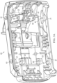
FIG. 2A is a top perspective of a lower housing of the battery pack ofFig. 1 . -
FIG. 2B is a perspective of the lower housing of the battery pack ofFig. 1 . -
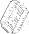
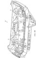
FIG. 3A is a bottom perspective of an upper housing of the battery pack ofFig. 1 . -
FIG. 3B is another bottom perspective of the upper housing of the battery pack ofFig. 1 . -
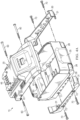
Fig. 4A is a partially exploded top perspective view of an outer housing of the battery pack ofFig. 1 . -
Fig. 4B is another partially exploded top perspective view of the outer housing of the battery pack ofFig. 1 . -
FIG. 5 is a top perspective view of the battery pack ofFig. 1 wit the upper housing removed. -
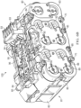
FIG. 6A is a top perspective view of the internal components of the battery pack ofFig. 1 . -
FIG. 6B is another top perspective view of the internal components of the battery pack ofFig. 1 . -
FIG. 7A is a cross-sectional view of the battery pack ofFIG. 1 along thelines 7A-7A ofFIG. 1 . -
FIG. 7B is a cross-sectional view of the battery pack ofFIG. 1 along thelines 7B-7B ofFIG. 1 . -
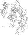
FIG. 8 is a top perspective of a terminal block of the battery pack ofFig. 1 . - Before any independent embodiments of the invention are explained in detail, it is to be understood that the invention is not limited in its application to the details of construction and the arrangement of components set forth in the following description or illustrated in the following drawings. The invention is capable of other independent embodiments and of being practiced or of being carried out in various ways. Also, it is to be understood that the phraseology and terminology used herein is for the purpose of description and should not be regarded as limiting.
- The use of "including," "comprising," or "having" and variations thereof herein is meant to encompass the items listed thereafter and equivalents thereof as well as additional items. Unless specified or limited otherwise, the terms "mounted," "connected," "supported," and "coupled" and variations thereof are used broadly and encompass both direct and indirect mountings, connections, supports, and couplings. Further, "connected" and "coupled" are not restricted to physical or mechanical connections or couplings.
- Relative terminology, such as, for example, "about", "approximately", "substantially", etc., used in connection with a quantity or condition would be understood by those of ordinary skill to be inclusive of the stated value and has the meaning dictated by the context (for example, the term includes at least the degree of error associated with the measurement of, tolerances (e.g., manufacturing, assembly, use, etc.) associated with the particular value, etc.). Such terminology should also be considered as disclosing the range defined by the absolute values of the two endpoints. For example, the expression "from about 2 to about 4" also discloses the range "from 2 to 4". The relative terminology may refer to plus or minus a percentage (e.g., 1%, 5%, 10% or more) of an indicated value.
- Also, the functionality described herein as being performed by one component may be performed by multiple components in a distributed manner. Likewise, functionality performed by multiple components may be consolidated and performed by a single component. Similarly, a component described as performing particular functionality may also perform additional functionality not described herein. For example, a device or structure that is "configured" in a certain way is configured in at least that way but may also be configured in ways that are not listed.
-
FIG. 1 illustrates a removable andrechargeable battery pack 10 operable to selectively power an electrical device (not shown; e.g., a power tool (e.g., a drill, a driver, a saw, a nailer, a grinder, etc.), an outdoor tool (e.g., a trimmer, a pole saw, etc.), etc., and another electrical device (e.g., a motorized device, a non-motorized device, etc.)). Thebattery pack 10 is also connectable to a charger (not shown) for charging. - The
battery pack 10 includes anouter housing 15 formed, in the illustrated construction, of anupper housing portion 20 and alower housing portion 25. Thebattery pack 10 also includes a battery cell carrier 80 (e.g., a battery cell core;FIGS. 6A and6B ) coupled to theouter housing 15 between theupper housing portion 20 and thelower housing portion 25. In the illustrated construction, a pair ofprotective cap elements 30 are connected to thelower housing portion 25 at the bottom and on either lateral side. - In the illustrated construction, the
upper housing portion 20 is connected to thebattery cell carrier 80 with threaded fasteners 60 (e.g., screws) that extend through complementary fastening holes 61 and 62 (Figs. 3A-4B ,7A ,7B ). In the illustrated construction, thelower housing portion 25 and theprotective cap elements 30 are connected to thebattery cell carrier 80 with threadedfasteners 70 that extend through complementary fastening holes 71 form in thelower housing portion 25 and complementary fastening holes 72 formed in each of theprotective cap elements 30. In other constructions (not shown), thehousing portions protective cap elements 30 are connected with other suitable coupling means. Together, theupper housing portion 20 and thelower housing portion 25 define an internal compartment within theouter housing 15 containing internal components 100 (FIG. 5 ), including thebattery cell carrier 80 of thebattery pack 10. The internal compartment is formed primarily from theinternal cavity 55 formed by the lower housing portion 25 (FIGS. 2A ,2B ). - In the illustrated construction, the lower housing 25 (
FIGS. 2A ,2B ) includes a number of drainage holes 27 formed on the lateral sides and adjacent to abottom surface 26. Thelower housing 25 also includes drainage holes 28 formed on both the front and back sides and adjacent to abottom surface 26. Each of the drainage holes 27 and 28 communicating between the inside of thelower housing 25 Four drainage holes 27 are depicted on each lateral side and twodrainage holes 28 are depicted on each of the front and back sides; however, other constructions may include more or less drainage holes. In the illustrated construction, thelower housing 25 also includes vent holes 29 formed on thebottom surface 26 through which air flows into theouter housing 15 from the outside of theouter housing 15. Six vent holes 29 are depicted; however, other constructions may include more or less vent holes. - The
upper housing portion 20 includes connection features 35 that are operable to selectively couple thebattery pack 10 to an electrical device (e.g., a drill, a reciprocating saw, a grinder, etc.) (not shown). For example, the connection features 35 includerails 40 that are sized to slidably interface with the electrical device and at least onelatch 45 that holds thebattery pack 10 to the electrical device. At least onerelease actuator 50 is coupled to theupper housing portion 20 and is operable to move thelatch 45 to detach thebattery pack 10 from the electrical device. In other embodiments, thebattery pack 10 can be coupled to a different implement (e.g., portable lighting, lawn care equipment such as lawn mowers, chainsaws, blowers, etc.). In further embodiments, thebattery pack 10 can be configured as a stem-style battery pack.Terminal openings 46 are formed in the connection features 35 adjacent battery pack terminals 93 (Figs. 5-6B , and8 ). Theterminal openings 46 provide access to thebattery pack terminals 93 to provide an electrical connection between thebattery pack 10 and the electrical device - With reference to
FIG. 5 , thebattery cell carrier 80 supported inside theouter housing 15 within the internal compartment. In the illustrated construction, thebattery cell carrier 80 is received within acavity 55 of thelower housing portion 25 for thelower housing portion 25 to support thebattery cell carrier 80. - With reference to
FIGS. 6A and6B , thebattery cell carrier 80 includes amodule frame 81 that supports battery cells 90 (e.g., cylindrical-shaped battery cells) in a compact arrangement within thebattery pack 10. In the illustrated construction, themodule frame 81 includes first and second frame halves 82, 83 connected with threaded fasteners 85 (e.g., screws) (Fig. 6B ). When assembled, the frame halves 82, 83 define a cell compartment (not shown) in which thebattery cells 90 are positioned and secured. Thebattery cells 90 extend along respectivelongitudinal axes 91, and the frame halves 82, 83 support the opposite axial ends of eachcell 90. - The
battery cell carrier 80 also includes acircuit board 96 coupled to aterminal block 94 on the top surface (e.g., top side) of thebattery cell carrier 80. Thecircuit board 96 and is in electrical communication with thecell connectors 88 and thebattery pack terminals 93. Theillustrated cell connectors 88 are coupled to lateral sides of the module frame 81and includecontacts 89 that extend through openings formed in themodule frame 81 to engage thecell terminals 92 at the ends of thebattery cells 90. Thecell connectors 88 electrically connectcell terminals 92 of thebattery cells 90 with thebattery pack terminals 93. - The illustrated
battery pack terminals 93 are also coupled to theterminal block 94 on the top side of thebattery cell carrier 80 and provides electrical communication between thebattery cell carrier 80 and the electrical device when thebattery pack 10 is coupled to the electrical device. In some constructions, thebattery cell carrier 80 includes a nominal voltage of about 18 volts. In other constructions, the nominal voltage of thebattery cell carrier 80 can be greater or less than 18 volts (e.g., 12 volts, 40 volts, etc.). In the illustrated construction, theterminal block 94 includes strap elements 95 (FIGS. 6A ,6B ,8 ) that are coupled to thecell connectors 88 via laser welding. - With reference to
FIGS. 3A ,3B ,7A , and7B theupper housing portion 20 is connected to thebattery cell carrier 80 with threadedfasteners 60 that extend through complementary fastening holes 61 and 62 and through a one of thescrew bosses 84 formed on thefirst frame half 82 and thescrew bosses upper housing portion 20 creating a double shear condition on each side of each of thescrew bosses 84. In the depicted construction, the threadedfasteners 60 pass through theupper housing portion 20 twice on each side of thebattery cell carrier 80 via theexternal screw bosses 21 formingfastening holes 61 and theinternal screw bosses 22 forming fastening holes 22. - One or more independent features and/or independent advantages of the invention may be set forth in the claims.
- Various aspects of the present disclosure may take any one or more of the following example configurations:
- EEE(1) A battery pack configured to be coupled to an electrical device, the battery pack comprising: a plurality of battery cells; a battery cell carrier configured to support the plurality of battery cells, the battery cell carrier having a plurality of connector screw bosses formed on a top side; a housing having an upper housing portion and a lower housing portion defining an internal compartment configured to receive the battery cell carrier, the upper housing portion having an outer screw boss on each lateral side and a respective inner screw boss formed on an inner surface of the upper housing portion; and wherein the upper housing portion is connected to the battery cell carrier with a plurality of first threaded fasteners each extending through one of the outer screw bosses, a respective one of the plurality of connector screw bosses, and a respective inner screw boss creating a double shear condition on each side of each of respective one of the plurality of connector screw bosses.
- EEE(2) The battery pack according to EEE(1), wherein the housing includes a lower housing portion.
- EEE(3) The battery pack according to EEE(1) or EEE(2), wherein the upper housing portion and the lower housing portion define an internal compartment configured to receive the battery cell carrier.
- EEE(4) The battery pack according to any one of EEE(1) to EEE(3), wherein each of the outer screw bosses, the respective one of the plurality of connector screw bosses, and the respective inner screw bosses are aligned.
- EEE(5) The battery pack according to any one of EEE(1) to EEE(4), wherein each of the plurality of first threaded fasteners pass through the upper housing portion twice and on one side of the battery cell carrier.
- EEE(6) The battery pack according to any one of EEE(1) to EEE(5), wherein the lower housing portion is connected to the battery cell carrier with a plurality of second threaded fasteners.
- EEE(7) The battery pack according to any one of EEE(1) to EEE(6), wherein the electrical device is a power tool.
- EEE(8) The battery pack according to any one of EEE(1) to EEE(7), wherein the battery cell carrier includes a first half portion and a second half portion.
- EEE(9) The battery pack according to any one of EEE(1) to EEE(8), wherein the first half portion and the second half portion are connected via a plurality of third threaded fasteners.
- EEE(10) The battery pack according to any one of EEE(1) to EEE(9), wherein the plurality of connector screw bosses is formed on the first half portion.
- EEE(11) The battery pack according to any one of EEE(1) to EEE(10), wherein each of the plurality of battery cells are cylindrical-shaped.
- EEE(12) The battery pack according to any one of EEE(1) to EEE(11), wherein the plurality of battery cells supported in the battery cell carrier are in a compact arrangement.
- EEE(13) The battery pack according to any one of EEE(1) to EEE(12), wherein the plurality of first threaded fasteners are screws.
- EEE(14) The battery pack according to any one of EEE(1) to EEE(13), further comprising a terminal block coupled to the battery cell carrier on the top side and providing electrical communication between the battery cell carrier and the electrical device.
- EEE(15) The battery pack according to any one of EEE(1) to EEE(14), wherein the battery cell carrier includes a plurality of cell connectors configured to engage with the cell terminals of each of the plurality of battery cells, and wherein the terminal block includes a plurality of strap elements each coupled to one of the plurality of cell connectors.
- EEE(16) A battery pack configured to be coupled to an electrical device, the battery pack comprising: a plurality of battery cells; a battery cell carrier configured to support the plurality of battery cells, the battery cell carrier having a plurality of connector screw bosses formed on a top side; a terminal block coupled to the battery cell carrier on the top side and providing electrical communication between the battery cell carrier and the electrical device; a housing having an upper housing portion comprising an outer screw boss on each lateral side and a respective inner screw boss formed on an inner surface of the lower housing portion; and wherein the upper housing portion is connected to the battery cell carrier with a plurality of first threaded fasteners each extending through one of the outer screw bosses, a respective one of the plurality of connector screw bosses, and a respective inner screw boss creating a double shear condition on each side of each of respective one of the plurality of connector screw bosses.
- EEE(17) The battery pack according to EEE(16), wherein the housing includes a lower housing portion.
- EEE(18) The battery pack according to EEE(16) or EEE(17), wherein the upper housing portion and the lower housing portion define an internal compartment configured to receive the battery cell carrier.
- EEE(19) The battery pack according to any one of EEE(16) to EEE(18), wherein each of the outer screw bosses, the respective one of the plurality of connector screw bosses, and the respective inner screw bosses are aligned.
- EEE(20) The battery pack according to any one of EEE(16) to EEE(19), wherein each of the plurality of first threaded fasteners pass through the upper housing portion twice and on one side of the battery cell carrier.
- EEE(21) The battery pack according to any one of EEE(16) to EEE(20), wherein the lower housing portion is connected to the battery cell carrier with a plurality of second threaded fasteners.
- EEE(22) The battery pack according to any one of EEE(16) to EEE(21), wherein the electrical device is a power tool.
- EEE(23) The battery pack according to any one of EEE(16) to EEE(22), wherein the battery cell carrier includes a first half portion and a second half portion.
- EEE(24) The battery pack according to any one of EEE(16) to EEE(23), wherein the first half portion and the second half portion are connected via a plurality of third threaded fasteners.
- EEE(25) The battery pack according to any one of EEE(16) to EEE(24), wherein the plurality of connector screw bosses is formed on the first half portion.
- EEE(26) The battery pack according to any one of EEE(16) to EEE(25), wherein each of the plurality of battery cells are cylindrical-shaped.
- EEE(27) The battery pack according to any one of EEE(16) to EEE(26), wherein the plurality of battery cells supported in the battery cell carrier are in a compact arrangement.
- EEE(28) The battery pack according to any one of EEE(16) to EEE(27), wherein the plurality of first threaded fasteners are screws.
- EEE(29) A battery pack configured to be coupled to an electrical device, the battery pack comprising: a plurality of battery cells; a battery cell carrier configured to support the plurality of battery cells, the battery cell carrier having a plurality of connector screw bosses formed on a top side; a housing having an upper housing comprising an outer screw boss on each lateral side and a respective inner screw boss formed on an inner surface of the upper housing portion; and wherein the upper housing portion is connected to the battery cell carrier with a plurality of first threaded fasteners each extending through one of the outer screw bosses, a respective one of the plurality of connector screw bosses, and a respective inner screw boss creating a double shear condition on each side of each of respective one of the plurality of connector screw bosses, and wherein each of the outer screw bosses, the respective one of the plurality of connector screw bosses, and the respective inner screw bosses are aligned.
- EEE(30) The battery pack according to EEE(29), wherein the housing includes a lower housing portion.
- EEE(31) The battery pack according to EEE(29) or EEE(30), wherein the upper housing portion and the lower housing portion define an internal compartment configured to receive the battery cell carrier.
- EEE(32) The battery pack according to any one of EEE(29) to EEE(31), wherein each of the plurality of first threaded fasteners pass through the upper housing portion twice and on one side of the battery cell carrier.
- EEE(33) The battery pack according to any one of EEE(29) to EEE(32), wherein the lower housing portion is connected to the battery cell carrier with a plurality of second threaded fasteners.
- EEE(34) The battery pack according to any one of EEE(29) to EEE(33), wherein the electrical device is a power tool.
- EEE(35) The battery pack according to any one of EEE(29) to EEE(34), wherein the battery cell carrier includes a first half portion and a second half portion.
- EEE(36) The battery pack according to any one of EEE(29) to EEE(35), wherein the first half portion and the second half portion are connected via a plurality of third threaded fasteners.
- EEE(37) The battery pack according to any one of EEE(29) to EEE(36), wherein the plurality of connector screw bosses is formed on the first half portion.
- EEE(38) The battery pack according to any one of EEE(29) to EEE(37), wherein each of the plurality of battery cells are cylindrical-shaped.
- EEE(39) The battery pack according to any one of EEE(29) to EEE(38), wherein the plurality of battery cells supported in the battery cell carrier are in a compact arrangement.
- EEE(40) The battery pack according to any one of EEE(29) to EEE(39), wherein the plurality of first threaded fasteners are screws.
- EEE(41) The battery pack according to any one of EEE(29) to EEE(40), further comprising a terminal block coupled to the battery cell carrier on the top side and providing electrical communication between the battery cell carrier and the electrical device.
- EEE(42) The battery pack according to any one of EEE(29) to EEE(41), wherein the battery cell carrier includes a plurality of cell connectors configured to engage with the cell terminals of each of the plurality of battery cells, and wherein the terminal block includes a plurality of strap elements each coupled to one of the plurality of cell connectors.
Claims (20)
- A battery pack configured to be coupled to an electrical device, the battery pack comprising:a plurality of battery cells;a battery cell carrier configured to support the plurality of battery cells, the battery cell carrier having a plurality of connector screw bosses formed on a top side;a housing having an upper housing portion and a lower housing portion defining an internal compartment configured to receive the battery cell carrier, the upper housing portion having an outer screw boss on each lateral side and a respective inner screw boss formed on an inner surface of the upper housing portion; andwherein the upper housing portion is connected to the battery cell carrier with a plurality of first threaded fasteners each extending through one of the outer screw bosses, a respective one of the plurality of connector screw bosses, and a respective inner screw boss creating a double shear condition on each side of each of respective one of the plurality of connector screw bosses.
- The battery pack of claim 1, wherein each of the outer screw bosses, the respective one of the plurality of connector screw bosses, and the respective inner screw bosses are aligned.
- The battery pack of claim 1, wherein each of the plurality of first threaded fasteners pass through the upper housing portion twice and on one side of the battery cell carrier.
- The battery pack of claim 1, wherein the lower housing portion is connected to the battery cell carrier with a plurality of second threaded fasteners.
- The battery pack of claim 1, wherein the electrical device is a power tool.
- The battery pack of claim 1, wherein the battery cell carrier includes a first half portion and a second half portion.
- The battery pack of claim 6, wherein the first half portion and the second half portion are connected via a plurality of third threaded fasteners.
- The battery pack of claim 6, wherein the plurality of connector screw bosses is formed on the first half portion.
- The battery pack of claim 1, wherein each of the plurality of battery cells are cylindrical-shaped.
- The battery pack of claim 1, wherein the plurality of battery cells supported in the battery cell carrier are in a compact arrangement.
- The battery pack of claim 1, wherein the plurality of first threaded fasteners are screws.
- The battery pack of claim 1, further comprising a terminal block coupled to the battery cell carrier on the top side and providing electrical communication between the battery cell carrier and the electrical device.
- The battery pack of claim 12, wherein the battery cell carrier includes a plurality of cell connectors configured to engage with the cell terminals of each of the plurality of battery cells, and wherein the terminal block includes a plurality of strap elements each coupled to one of the plurality of cell connectors.
- A battery pack configured to be coupled to an electrical device, the battery pack comprising:a plurality of battery cells;a battery cell carrier configured to support the plurality of battery cells, the battery cell carrier having a plurality of connector screw bosses formed on a top side;a terminal block coupled to the battery cell carrier on the top side and providing electrical communication between the battery cell carrier and the electrical device;a housing having an upper housing portion comprising an outer screw boss on each lateral side and a respective inner screw boss formed on an inner surface of the lower housing portion; andwherein the upper housing portion is connected to the battery cell carrier with a plurality of first threaded fasteners each extending through one of the outer screw bosses, a respective one of the plurality of connector screw bosses, and a respective inner screw boss creating a double shear condition on each side of each of respective one of the plurality of connector screw bosses.
- The battery pack of claim 14, wherein the housing includes a lower housing portion, wherein the upper housing portion and the lower housing portion define an internal compartment configured to receive the battery cell carrier.
- The battery pack of claim 15, wherein the lower housing portion is connected to the battery cell carrier with a plurality of second threaded fasteners.
- The battery pack of claim 14, wherein the battery cell carrier includes a plurality of cell connectors configured to engage with the cell terminals of each of the plurality of battery cells, and wherein the terminal block includes a plurality of strap elements each coupled to one of the plurality of cell connectors.
- A battery pack configured to be coupled to an electrical device, the battery pack comprising:a plurality of battery cells;a battery cell carrier configured to support the plurality of battery cells, the battery cell carrier having a plurality of connector screw bosses formed on a top side;a housing having an upper housing comprising an outer screw boss on each lateral side and a respective inner screw boss formed on an inner surface of the upper housing portion; andwherein the upper housing portion is connected to the battery cell carrier with a plurality of first threaded fasteners each extending through one of the outer screw bosses, a respective one of the plurality of connector screw bosses, and a respective inner screw boss creating a double shear condition on each side of each of respective one of the plurality of connector screw bosses, andwherein each of the outer screw bosses, the respective one of the plurality of connector screw bosses, and the respective inner screw bosses are aligned.
- The battery pack of claim 18, further comprising a terminal block coupled to the battery cell carrier on the top side and providing electrical communication between the battery cell carrier and the electrical device.
- The battery pack of claim 19, wherein the battery cell carrier includes a plurality of cell connectors configured to engage with the cell terminals of each of the plurality of battery cells, and wherein the terminal block includes a plurality of strap elements each coupled to one of the plurality of cell connectors.
Applications Claiming Priority (1)
| Application Number | Priority Date | Filing Date | Title |
|---|---|---|---|
| US202263316820P | 2022-03-04 | 2022-03-04 |
Publications (3)
| Publication Number | Publication Date |
|---|---|
| EP4239770A2 true EP4239770A2 (en) | 2023-09-06 |
| EP4239770A3 EP4239770A3 (en) | 2024-06-12 |
| EP4239770B1 EP4239770B1 (en) | 2025-10-01 |
Family
ID=85505466
Family Applications (1)
| Application Number | Title | Priority Date | Filing Date |
|---|---|---|---|
| EP23160066.9A Active EP4239770B1 (en) | 2022-03-04 | 2023-03-03 | Battery pack with double shear connection |
Country Status (3)
| Country | Link |
|---|---|
| US (1) | US20230282920A1 (en) |
| EP (1) | EP4239770B1 (en) |
| CN (1) | CN220382217U (en) |
Cited By (1)
| Publication number | Priority date | Publication date | Assignee | Title |
|---|---|---|---|---|
| EP4383416A3 (en) * | 2022-12-06 | 2024-08-21 | Milwaukee Electric Tool Corporation | Battery pack assembly |
Families Citing this family (2)
| Publication number | Priority date | Publication date | Assignee | Title |
|---|---|---|---|---|
| USD1122188S1 (en) * | 2025-04-18 | 2026-04-14 | Shenzhen Jinjunye Electronics Co., Ltd. | Power tool battery |
| USD1122189S1 (en) * | 2025-05-12 | 2026-04-14 | Shenzhen Jinjunye Electronics Co., Ltd. | Power tool battery |
Citations (3)
| Publication number | Priority date | Publication date | Assignee | Title |
|---|---|---|---|---|
| US20190027720A1 (en) * | 2016-03-02 | 2019-01-24 | Robert Bosch Gmbh | Battery pack for a hand-held power tool |
| DE102017217503A1 (en) * | 2017-09-29 | 2019-04-04 | Robert Bosch Gmbh | battery Pack |
| WO2021144153A1 (en) * | 2020-01-13 | 2021-07-22 | Robert Bosch Gmbh | Battery pack for a hand-held power tool, hand-held power tool and charging device |
Family Cites Families (4)
| Publication number | Priority date | Publication date | Assignee | Title |
|---|---|---|---|---|
| JP5847559B2 (en) * | 2011-11-25 | 2016-01-27 | 三洋電機株式会社 | Battery pack |
| DE102016203429A1 (en) * | 2016-03-02 | 2017-09-07 | Robert Bosch Gmbh | Battery pack for a hand tool |
| DE102017217495A1 (en) * | 2017-09-29 | 2019-04-04 | Robert Bosch Gmbh | battery Pack |
| US11145932B2 (en) * | 2018-09-24 | 2021-10-12 | Milwaukee Electric Tool Corporation | Battery cell module and battery pack |
-
2023
- 2023-03-03 EP EP23160066.9A patent/EP4239770B1/en active Active
- 2023-03-03 US US18/178,198 patent/US20230282920A1/en active Pending
- 2023-03-06 CN CN202320419339.XU patent/CN220382217U/en active Active
Patent Citations (3)
| Publication number | Priority date | Publication date | Assignee | Title |
|---|---|---|---|---|
| US20190027720A1 (en) * | 2016-03-02 | 2019-01-24 | Robert Bosch Gmbh | Battery pack for a hand-held power tool |
| DE102017217503A1 (en) * | 2017-09-29 | 2019-04-04 | Robert Bosch Gmbh | battery Pack |
| WO2021144153A1 (en) * | 2020-01-13 | 2021-07-22 | Robert Bosch Gmbh | Battery pack for a hand-held power tool, hand-held power tool and charging device |
Cited By (1)
| Publication number | Priority date | Publication date | Assignee | Title |
|---|---|---|---|---|
| EP4383416A3 (en) * | 2022-12-06 | 2024-08-21 | Milwaukee Electric Tool Corporation | Battery pack assembly |
Also Published As
| Publication number | Publication date |
|---|---|
| CN220382217U (en) | 2024-01-23 |
| US20230282920A1 (en) | 2023-09-07 |
| EP4239770A3 (en) | 2024-06-12 |
| EP4239770B1 (en) | 2025-10-01 |
Similar Documents
| Publication | Publication Date | Title |
|---|---|---|
| EP4239770A2 (en) | Battery pack with double shear connection | |
| EP2448037B1 (en) | Electric power tool system | |
| US6329788B1 (en) | Cordless power tool system | |
| US11677118B2 (en) | Battery cell module and battery pack | |
| EP1363339B1 (en) | Cordles power tool system | |
| AU2014301796B2 (en) | Battery pack,tool battery and battery operated tool | |
| US8764852B2 (en) | Battery pack including an electric harness and method of manufacturing the same | |
| EP1727223A1 (en) | Battery pack | |
| KR20240050473A (en) | battery pack | |
| US20220115714A1 (en) | Battery pack | |
| JP3093893U (en) | Electric tool | |
| EP4111527B1 (en) | Battery pack | |
| CN210732360U (en) | Electric tool and battery connector for electric tool | |
| CN115051096A (en) | Battery pack | |
| WO2024212161A1 (en) | Battery pack and its manufacturing method | |
| CN216450770U (en) | General type electric appliance battery assembly interface structure | |
| EP2748880A1 (en) | Battery pack and battery powered tool | |
| JP2026061050A (en) | Battery pack | |
| CN121460843A (en) | Power tool system and power supply system |
Legal Events
| Date | Code | Title | Description |
|---|---|---|---|
| PUAI | Public reference made under article 153(3) epc to a published international application that has entered the european phase |
Free format text: ORIGINAL CODE: 0009012 |
|
| STAA | Information on the status of an ep patent application or granted ep patent |
Free format text: STATUS: THE APPLICATION HAS BEEN PUBLISHED |
|
| AK | Designated contracting states |
Kind code of ref document: A2 Designated state(s): AL AT BE BG CH CY CZ DE DK EE ES FI FR GB GR HR HU IE IS IT LI LT LU LV MC ME MK MT NL NO PL PT RO RS SE SI SK SM TR |
|
| PUAL | Search report despatched |
Free format text: ORIGINAL CODE: 0009013 |
|
| AK | Designated contracting states |
Kind code of ref document: A3 Designated state(s): AL AT BE BG CH CY CZ DE DK EE ES FI FR GB GR HR HU IE IS IT LI LT LU LV MC ME MK MT NL NO PL PT RO RS SE SI SK SM TR |
|
| RIC1 | Information provided on ipc code assigned before grant |
Ipc: B25F 5/02 20060101ALI20240507BHEP Ipc: H01M 50/244 20210101ALI20240507BHEP Ipc: H01M 50/507 20210101ALI20240507BHEP Ipc: H01M 50/296 20210101ALI20240507BHEP Ipc: H01M 50/262 20210101ALI20240507BHEP Ipc: H01M 50/247 20210101ALI20240507BHEP Ipc: H01M 50/213 20210101AFI20240507BHEP |
|
| STAA | Information on the status of an ep patent application or granted ep patent |
Free format text: STATUS: REQUEST FOR EXAMINATION WAS MADE |
|
| 17P | Request for examination filed |
Effective date: 20241210 |
|
| GRAP | Despatch of communication of intention to grant a patent |
Free format text: ORIGINAL CODE: EPIDOSNIGR1 |
|
| STAA | Information on the status of an ep patent application or granted ep patent |
Free format text: STATUS: GRANT OF PATENT IS INTENDED |
|
| INTG | Intention to grant announced |
Effective date: 20250424 |
|
| RIC1 | Information provided on ipc code assigned before grant |
Ipc: B25F 5/02 20060101ALI20250411BHEP Ipc: H01M 50/244 20210101ALI20250411BHEP Ipc: H01M 50/507 20210101ALI20250411BHEP Ipc: H01M 50/296 20210101ALI20250411BHEP Ipc: H01M 50/262 20210101ALI20250411BHEP Ipc: H01M 50/271 20210101ALI20250411BHEP Ipc: H01M 50/247 20210101ALI20250411BHEP Ipc: H01M 50/213 20210101AFI20250411BHEP |
|
| GRAS | Grant fee paid |
Free format text: ORIGINAL CODE: EPIDOSNIGR3 |
|
| GRAA | (expected) grant |
Free format text: ORIGINAL CODE: 0009210 |
|
| STAA | Information on the status of an ep patent application or granted ep patent |
Free format text: STATUS: THE PATENT HAS BEEN GRANTED |
|
| AK | Designated contracting states |
Kind code of ref document: B1 Designated state(s): AL AT BE BG CH CY CZ DE DK EE ES FI FR GB GR HR HU IE IS IT LI LT LU LV MC ME MK MT NL NO PL PT RO RS SE SI SK SM TR |
|
| REG | Reference to a national code |
Ref country code: GB Ref legal event code: FG4D Ref country code: CH Ref legal event code: F10 Free format text: ST27 STATUS EVENT CODE: U-0-0-F10-F00 (AS PROVIDED BY THE NATIONAL OFFICE) Effective date: 20251001 |
|
| REG | Reference to a national code |
Ref country code: DE Ref legal event code: R096 Ref document number: 602023007012 Country of ref document: DE |
|
| REG | Reference to a national code |
Ref country code: IE Ref legal event code: FG4D |
|
| REG | Reference to a national code |
Ref country code: NL Ref legal event code: MP Effective date: 20251001 |
|
| REG | Reference to a national code |
Ref country code: AT Ref legal event code: MK05 Ref document number: 1843512 Country of ref document: AT Kind code of ref document: T Effective date: 20251001 |
|
| PG25 | Lapsed in a contracting state [announced via postgrant information from national office to epo] |
Ref country code: NL Free format text: LAPSE BECAUSE OF FAILURE TO SUBMIT A TRANSLATION OF THE DESCRIPTION OR TO PAY THE FEE WITHIN THE PRESCRIBED TIME-LIMIT Effective date: 20251001 |
|
| PG25 | Lapsed in a contracting state [announced via postgrant information from national office to epo] |
Ref country code: ES Free format text: LAPSE BECAUSE OF FAILURE TO SUBMIT A TRANSLATION OF THE DESCRIPTION OR TO PAY THE FEE WITHIN THE PRESCRIBED TIME-LIMIT Effective date: 20251001 |
|
| REG | Reference to a national code |
Ref country code: LT Ref legal event code: MG9D |
|
| PG25 | Lapsed in a contracting state [announced via postgrant information from national office to epo] |
Ref country code: NO Free format text: LAPSE BECAUSE OF FAILURE TO SUBMIT A TRANSLATION OF THE DESCRIPTION OR TO PAY THE FEE WITHIN THE PRESCRIBED TIME-LIMIT Effective date: 20260101 |
|
| PGFP | Annual fee paid to national office [announced via postgrant information from national office to epo] |
Ref country code: DE Payment date: 20260327 Year of fee payment: 4 |
|
| PG25 | Lapsed in a contracting state [announced via postgrant information from national office to epo] |
Ref country code: AT Free format text: LAPSE BECAUSE OF FAILURE TO SUBMIT A TRANSLATION OF THE DESCRIPTION OR TO PAY THE FEE WITHIN THE PRESCRIBED TIME-LIMIT Effective date: 20251001 Ref country code: HR Free format text: LAPSE BECAUSE OF FAILURE TO SUBMIT A TRANSLATION OF THE DESCRIPTION OR TO PAY THE FEE WITHIN THE PRESCRIBED TIME-LIMIT Effective date: 20251001 Ref country code: FI Free format text: LAPSE BECAUSE OF FAILURE TO SUBMIT A TRANSLATION OF THE DESCRIPTION OR TO PAY THE FEE WITHIN THE PRESCRIBED TIME-LIMIT Effective date: 20251001 |
|
| PG25 | Lapsed in a contracting state [announced via postgrant information from national office to epo] |
Ref country code: RS Free format text: LAPSE BECAUSE OF FAILURE TO SUBMIT A TRANSLATION OF THE DESCRIPTION OR TO PAY THE FEE WITHIN THE PRESCRIBED TIME-LIMIT Effective date: 20260101 |
|
| PG25 | Lapsed in a contracting state [announced via postgrant information from national office to epo] |
Ref country code: IS Free format text: LAPSE BECAUSE OF FAILURE TO SUBMIT A TRANSLATION OF THE DESCRIPTION OR TO PAY THE FEE WITHIN THE PRESCRIBED TIME-LIMIT Effective date: 20260201 |
|
| PG25 | Lapsed in a contracting state [announced via postgrant information from national office to epo] |
Ref country code: PT Free format text: LAPSE BECAUSE OF FAILURE TO SUBMIT A TRANSLATION OF THE DESCRIPTION OR TO PAY THE FEE WITHIN THE PRESCRIBED TIME-LIMIT Effective date: 20260202 Ref country code: CZ Free format text: LAPSE BECAUSE OF FAILURE TO SUBMIT A TRANSLATION OF THE DESCRIPTION OR TO PAY THE FEE WITHIN THE PRESCRIBED TIME-LIMIT Effective date: 20251001 |
|
| PG25 | Lapsed in a contracting state [announced via postgrant information from national office to epo] |
Ref country code: PL Free format text: LAPSE BECAUSE OF FAILURE TO SUBMIT A TRANSLATION OF THE DESCRIPTION OR TO PAY THE FEE WITHIN THE PRESCRIBED TIME-LIMIT Effective date: 20251001 |
|
| PG25 | Lapsed in a contracting state [announced via postgrant information from national office to epo] |
Ref country code: LV Free format text: LAPSE BECAUSE OF FAILURE TO SUBMIT A TRANSLATION OF THE DESCRIPTION OR TO PAY THE FEE WITHIN THE PRESCRIBED TIME-LIMIT Effective date: 20251001 |