EP4239757A1 - Battery, and method and device for inhibiting battery inflation - Google Patents
Battery, and method and device for inhibiting battery inflation Download PDFInfo
- Publication number
- EP4239757A1 EP4239757A1 EP22783850.5A EP22783850A EP4239757A1 EP 4239757 A1 EP4239757 A1 EP 4239757A1 EP 22783850 A EP22783850 A EP 22783850A EP 4239757 A1 EP4239757 A1 EP 4239757A1
- Authority
- EP
- European Patent Office
- Prior art keywords
- battery
- gas reducer
- gas
- electrode plate
- reducer
- Prior art date
- Legal status (The legal status is an assumption and is not a legal conclusion. Google has not performed a legal analysis and makes no representation as to the accuracy of the status listed.)
- Pending
Links
Images



Classifications
-
- H—ELECTRICITY
- H01—ELECTRIC ELEMENTS
- H01M—PROCESSES OR MEANS, e.g. BATTERIES, FOR THE DIRECT CONVERSION OF CHEMICAL ENERGY INTO ELECTRICAL ENERGY
- H01M4/00—Electrodes
- H01M4/02—Electrodes composed of, or comprising, active material
- H01M4/13—Electrodes for accumulators with non-aqueous electrolyte, e.g. for lithium-accumulators; Processes of manufacture thereof
-
- H—ELECTRICITY
- H01—ELECTRIC ELEMENTS
- H01M—PROCESSES OR MEANS, e.g. BATTERIES, FOR THE DIRECT CONVERSION OF CHEMICAL ENERGY INTO ELECTRICAL ENERGY
- H01M4/00—Electrodes
- H01M4/02—Electrodes composed of, or comprising, active material
- H01M4/64—Carriers or collectors
- H01M4/66—Selection of materials
- H01M4/665—Composites
- H01M4/667—Composites in the form of layers, e.g. coatings
-
- H—ELECTRICITY
- H01—ELECTRIC ELEMENTS
- H01M—PROCESSES OR MEANS, e.g. BATTERIES, FOR THE DIRECT CONVERSION OF CHEMICAL ENERGY INTO ELECTRICAL ENERGY
- H01M10/00—Secondary cells; Manufacture thereof
- H01M10/05—Accumulators with non-aqueous electrolyte
- H01M10/052—Li-accumulators
-
- H—ELECTRICITY
- H01—ELECTRIC ELEMENTS
- H01M—PROCESSES OR MEANS, e.g. BATTERIES, FOR THE DIRECT CONVERSION OF CHEMICAL ENERGY INTO ELECTRICAL ENERGY
- H01M10/00—Secondary cells; Manufacture thereof
- H01M10/05—Accumulators with non-aqueous electrolyte
- H01M10/052—Li-accumulators
- H01M10/0525—Rocking-chair batteries, i.e. batteries with lithium insertion or intercalation in both electrodes; Lithium-ion batteries
-
- H—ELECTRICITY
- H01—ELECTRIC ELEMENTS
- H01M—PROCESSES OR MEANS, e.g. BATTERIES, FOR THE DIRECT CONVERSION OF CHEMICAL ENERGY INTO ELECTRICAL ENERGY
- H01M10/00—Secondary cells; Manufacture thereof
- H01M10/05—Accumulators with non-aqueous electrolyte
- H01M10/054—Accumulators with insertion or intercalation of metals other than lithium, e.g. with magnesium or aluminium
-
- H—ELECTRICITY
- H01—ELECTRIC ELEMENTS
- H01M—PROCESSES OR MEANS, e.g. BATTERIES, FOR THE DIRECT CONVERSION OF CHEMICAL ENERGY INTO ELECTRICAL ENERGY
- H01M10/00—Secondary cells; Manufacture thereof
- H01M10/42—Methods or arrangements for servicing or maintenance of secondary cells or secondary half-cells
- H01M10/4235—Safety or regulating additives or arrangements in electrodes, separators or electrolyte
-
- H—ELECTRICITY
- H01—ELECTRIC ELEMENTS
- H01M—PROCESSES OR MEANS, e.g. BATTERIES, FOR THE DIRECT CONVERSION OF CHEMICAL ENERGY INTO ELECTRICAL ENERGY
- H01M10/00—Secondary cells; Manufacture thereof
- H01M10/42—Methods or arrangements for servicing or maintenance of secondary cells or secondary half-cells
- H01M10/52—Removing gases inside the secondary cell, e.g. by absorption
-
- H—ELECTRICITY
- H01—ELECTRIC ELEMENTS
- H01M—PROCESSES OR MEANS, e.g. BATTERIES, FOR THE DIRECT CONVERSION OF CHEMICAL ENERGY INTO ELECTRICAL ENERGY
- H01M10/00—Secondary cells; Manufacture thereof
- H01M10/42—Methods or arrangements for servicing or maintenance of secondary cells or secondary half-cells
- H01M10/52—Removing gases inside the secondary cell, e.g. by absorption
- H01M10/526—Removing gases inside the secondary cell, e.g. by absorption by gas recombination on the electrode surface or by structuring the electrode surface to improve gas recombination
-
- H—ELECTRICITY
- H01—ELECTRIC ELEMENTS
- H01M—PROCESSES OR MEANS, e.g. BATTERIES, FOR THE DIRECT CONVERSION OF CHEMICAL ENERGY INTO ELECTRICAL ENERGY
- H01M4/00—Electrodes
- H01M4/02—Electrodes composed of, or comprising, active material
- H01M4/04—Processes of manufacture in general
- H01M4/043—Processes of manufacture in general involving compressing or compaction
- H01M4/0435—Rolling or calendering
-
- H—ELECTRICITY
- H01—ELECTRIC ELEMENTS
- H01M—PROCESSES OR MEANS, e.g. BATTERIES, FOR THE DIRECT CONVERSION OF CHEMICAL ENERGY INTO ELECTRICAL ENERGY
- H01M50/00—Constructional details or processes of manufacture of the non-active parts of electrochemical cells other than fuel cells, e.g. hybrid cells
- H01M50/10—Primary casings; Jackets or wrappings
- H01M50/116—Primary casings; Jackets or wrappings characterised by the material
- H01M50/117—Inorganic material
- H01M50/119—Metals
-
- H—ELECTRICITY
- H01—ELECTRIC ELEMENTS
- H01M—PROCESSES OR MEANS, e.g. BATTERIES, FOR THE DIRECT CONVERSION OF CHEMICAL ENERGY INTO ELECTRICAL ENERGY
- H01M50/00—Constructional details or processes of manufacture of the non-active parts of electrochemical cells other than fuel cells, e.g. hybrid cells
- H01M50/10—Primary casings; Jackets or wrappings
- H01M50/116—Primary casings; Jackets or wrappings characterised by the material
- H01M50/124—Primary casings; Jackets or wrappings characterised by the material having a layered structure
- H01M50/1243—Primary casings; Jackets or wrappings characterised by the material having a layered structure characterised by the internal coating on the casing
-
- H—ELECTRICITY
- H01—ELECTRIC ELEMENTS
- H01M—PROCESSES OR MEANS, e.g. BATTERIES, FOR THE DIRECT CONVERSION OF CHEMICAL ENERGY INTO ELECTRICAL ENERGY
- H01M50/00—Constructional details or processes of manufacture of the non-active parts of electrochemical cells other than fuel cells, e.g. hybrid cells
- H01M50/30—Arrangements for facilitating escape of gases
-
- H—ELECTRICITY
- H01—ELECTRIC ELEMENTS
- H01M—PROCESSES OR MEANS, e.g. BATTERIES, FOR THE DIRECT CONVERSION OF CHEMICAL ENERGY INTO ELECTRICAL ENERGY
- H01M10/00—Secondary cells; Manufacture thereof
- H01M10/05—Accumulators with non-aqueous electrolyte
- H01M10/056—Accumulators with non-aqueous electrolyte characterised by the materials used as electrolytes, e.g. mixed inorganic/organic electrolytes
- H01M10/0564—Accumulators with non-aqueous electrolyte characterised by the materials used as electrolytes, e.g. mixed inorganic/organic electrolytes the electrolyte being constituted of organic materials only
- H01M10/0566—Liquid materials
- H01M10/0569—Liquid materials characterised by the solvents
-
- H—ELECTRICITY
- H01—ELECTRIC ELEMENTS
- H01M—PROCESSES OR MEANS, e.g. BATTERIES, FOR THE DIRECT CONVERSION OF CHEMICAL ENERGY INTO ELECTRICAL ENERGY
- H01M2300/00—Electrolytes
- H01M2300/0017—Non-aqueous electrolytes
- H01M2300/0025—Organic electrolyte
- H01M2300/0028—Organic electrolyte characterised by the solvent
- H01M2300/0034—Fluorinated solvents
-
- H—ELECTRICITY
- H01—ELECTRIC ELEMENTS
- H01M—PROCESSES OR MEANS, e.g. BATTERIES, FOR THE DIRECT CONVERSION OF CHEMICAL ENERGY INTO ELECTRICAL ENERGY
- H01M4/00—Electrodes
- H01M4/02—Electrodes composed of, or comprising, active material
- H01M4/13—Electrodes for accumulators with non-aqueous electrolyte, e.g. for lithium-accumulators; Processes of manufacture thereof
- H01M4/131—Electrodes based on mixed oxides or hydroxides, or on mixtures of oxides or hydroxides, e.g. LiCoOx
-
- H—ELECTRICITY
- H01—ELECTRIC ELEMENTS
- H01M—PROCESSES OR MEANS, e.g. BATTERIES, FOR THE DIRECT CONVERSION OF CHEMICAL ENERGY INTO ELECTRICAL ENERGY
- H01M4/00—Electrodes
- H01M4/02—Electrodes composed of, or comprising, active material
- H01M4/36—Selection of substances as active materials, active masses, active liquids
- H01M4/48—Selection of substances as active materials, active masses, active liquids of inorganic oxides or hydroxides
- H01M4/50—Selection of substances as active materials, active masses, active liquids of inorganic oxides or hydroxides of manganese
- H01M4/505—Selection of substances as active materials, active masses, active liquids of inorganic oxides or hydroxides of manganese of mixed oxides or hydroxides containing manganese for inserting or intercalating light metals, e.g. LiMn2O4 or LiMn2OxFy
-
- H—ELECTRICITY
- H01—ELECTRIC ELEMENTS
- H01M—PROCESSES OR MEANS, e.g. BATTERIES, FOR THE DIRECT CONVERSION OF CHEMICAL ENERGY INTO ELECTRICAL ENERGY
- H01M4/00—Electrodes
- H01M4/02—Electrodes composed of, or comprising, active material
- H01M4/36—Selection of substances as active materials, active masses, active liquids
- H01M4/48—Selection of substances as active materials, active masses, active liquids of inorganic oxides or hydroxides
- H01M4/52—Selection of substances as active materials, active masses, active liquids of inorganic oxides or hydroxides of nickel, cobalt or iron
- H01M4/525—Selection of substances as active materials, active masses, active liquids of inorganic oxides or hydroxides of nickel, cobalt or iron of mixed oxides or hydroxides containing iron, cobalt or nickel for inserting or intercalating light metals, e.g. LiNiO2, LiCoO2 or LiCoOxFy
-
- Y—GENERAL TAGGING OF NEW TECHNOLOGICAL DEVELOPMENTS; GENERAL TAGGING OF CROSS-SECTIONAL TECHNOLOGIES SPANNING OVER SEVERAL SECTIONS OF THE IPC; TECHNICAL SUBJECTS COVERED BY FORMER USPC CROSS-REFERENCE ART COLLECTIONS [XRACs] AND DIGESTS
- Y02—TECHNOLOGIES OR APPLICATIONS FOR MITIGATION OR ADAPTATION AGAINST CLIMATE CHANGE
- Y02E—REDUCTION OF GREENHOUSE GAS [GHG] EMISSIONS, RELATED TO ENERGY GENERATION, TRANSMISSION OR DISTRIBUTION
- Y02E60/00—Enabling technologies; Technologies with a potential or indirect contribution to GHG emissions mitigation
- Y02E60/10—Energy storage using batteries
Definitions
- This application relates to the field of battery technologies, and in particular, to a battery, and a method and apparatus for curbing battery gassing.
- Secondary batteries have advantages such as long cycle life and environmental protection, and are widely applied in new energy industries.
- a solid electrolyte film formed on a surface of a negative electrode as a result of reduction by a non-aqueous electrolyte, partially decomposes to produce gas, and the non-aqueous electrolyte oxidizes on a surface of a positive electrode to also produce gas.
- these gases will lead to battery volume swelling, and flammable gases are included in these gases produced in the battery and cause safety risks to a certain extent.
- these gases dissolving in electrodes and the non-aqueous electrolyte will affect ion transmission and electron exchange in the non-aqueous electrolyte, degrading the cycling performance of the battery.
- the following two methods are mainly used to solve the battery gassing problem.
- the first method is disposing a vent valve. When gas produced reaches a given amount, it is exhausted to an air pocket through the vent valve.
- the foregoing method will complicate the structure of a battery and cannot eliminate the produced gas in a timely manner.
- the second method is disposing a gas storage apparatus inside the battery, and the gas produced is absorbed and stored in the gas storage apparatus.
- an absorption medium with a specific size effect can absorb only a particular type of gas, and the amount of absorption and storage is relatively small.
- This application is intended to provide a battery, and a method and apparatus for curbing battery gassing.
- a gas reducer is used for chemical consumption of gas produced, which helps achieve simple configuration, no limitation from gas scale effect, timely degassing, and high degassing capacity.
- an embodiment of this application provides a battery, including a battery housing, a positive electrode plate, a negative electrode plate, and a non-aqueous electrolyte.
- a gas reducer is disposed inside the battery housing, the gas reducer includes at least one of alkali metal and alkali metal alloy, and the gas reducer is in no contact with or in non-electrical contact with the negative electrode plate.
- the gas reducer is disposed inside the battery housing, which is easy to implement.
- Alkali metal and/or alkali metal alloy is selected as the gas reducer.
- the gas produced is reduced to an alkali metal salt relying on reducibility of the alkali metal and the alkali metal alloy, implementing chemical consumption of the gas. Such chemical consumption is not limited by gas size effect.
- multiple types of gas produced can be reduced in a quick and effective manner to achieve timely degassing and high degassing capacity.
- an amount of substance of the gas reducer is 1-10% of an amount of substance of a solvent of the non-aqueous electrolyte, optionally 3-5%.
- a molar ratio of the gas reducer to the solvent of the non-aqueous electrolyte is controlled to be within a specified range. In this way, effects of absorbing gas produced by the battery are ensured, and frequent side reactions between excessive gas reducer and the electrolyte can be avoided.
- a specific surface area of the gas reducer is 5-100m 2 /g, optionally 20-50m 2 /g.
- the specific surface area of the gas reducer is controlled to be within a specified range, ensuring that gas produced during battery cycling can be absorbed quickly, and avoiding a large specific surface area which causes serious side reactions between the gas reducer and the electrolyte.
- the gas reducer is lithium metal or sodium metal.
- a specified type of gas reducer is selected. In this way, chemical consumption of multiple types of gas produced such as carbon monoxide, carbon dioxide, sulfur dioxide, sulfur trioxide, and nitrogen can be effectively implemented.
- the gas reducer is disposed on a positive electrode current collector of the positive electrode plate.
- the gas reducer is disposed on the positive electrode current collector, so that the gas reducer can be electrically insulated from the negative electrode plate properly.
- the positive electrode current collector of the positive electrode plate at an end of a battery cell has a first surface and a second surface that are opposite, a positive-electrode material is disposed on the first surface, and the gas reducer is disposed on the second surface.
- the gas reducer is disposed at the end of the battery cell, ensuring that the gas reducer can better contact and absorb the gas produced.
- the gas reducer is disposed on an inner wall of the battery housing.
- the gas reducer is disposed on the inner wall of the battery housing. The gas reducer is relatively fixed in the battery and therefore physical stability of a battery structure is improved.
- the battery housing includes a battery cell compartment and an air pocket compartment that communicate with each other, the positive electrode plate and the negative electrode plate are disposed in the battery cell compartment, and the gas reducer is disposed on the inner wall of the housing of the battery cell compartment and/or the inner wall of the housing of the air pocket compartment.
- the gas reducer is attached to the inner wall of the housing, so that the gas reducer is relatively fixed in the battery. Disposing the gas reducer in the air pocket compartment is convenient, allowing the gas reducer to be electrically insulated from the negative electrode plate properly.
- the gas reducer is sheet-shaped. In this design, the gas reducer is sheet-shaped, so that it is easy to attach the gas reducer to the battery cell and the battery housing.
- the battery is a pouch battery, a prismatic battery, a button battery, or a cylindrical battery.
- the solvent of the non-aqueous electrolyte is a carbonate-based solvent, optionally a fluorocarbonate-based solvent.
- the solvent of the non-aqueous electrolyte is a carbonate-based solvent, and with a main component of CO 2 , gas produced by the electrolyte is highly active in reaction with the alkali metal gas reducer, ensuring that the gas reducer can better absorb the gas.
- the non-aqueous electrolyte is a fluorocarbonate-based electrolyte, a more stable surface passivation layer can be formed on a surface of the alkali metal gas reducer, reducing side reactions between the gas reducer and the electrolyte.
- the battery is a lithium-ion battery or a sodium-ion battery.
- the positive-electrode material of the positive electrode plate is a ternary positive-electrode material, lithium iron phosphate, sodium iron phosphate, or lithium cobalt oxide, and/or a negative-electrode material of the negative electrode plate is lithium metal, sodium metal, or graphite.
- the positive-electrode material of the battery is lithium nickel cobalt manganate or lithium nickel cobalt aluminate
- the negative-electrode material of the battery is lithium metal
- an embodiment of this application provides an apparatus, provided with the battery according to the embodiments of the first aspect.
- an embodiment of this application provides a method for curbing battery gassing.
- the method includes: disposing a gas reducer inside a battery housing, where the gas reducer is in no contact with or in non-electrical contact with a negative electrode plate, and the gas reducer includes at least one of alkali metal and alkali metal alloy.
- a positive-electrode material is disposed on a first surface of a positive electrode current collector and the gas reducer is disposed on a second surface to obtain a positive electrode plate; and the positive electrode plate is disposed at an end of a battery cell.
- the gas reducer is disposed on the positive electrode current collector, so that the gas reducer can be electrically insulated from the negative electrode plate properly.
- the gas reducer is formed on the positive electrode current collector in a roll-pressing manner.
- the gas reducer is formed in a roll-pressing manner so that it can be attached easily.
- Embodiments where specific conditions are not specified, are implemented in accordance with general conditions or those recommended by a manufacturer.
- the reagents or instruments used are all conventional products that can be purchased on the market if no manufacturer is indicated.
- solution A and/or solution B may be solution A alone, solution B alone, or solution A and solution B together.
- a plurality of means at least two.
- a metal or an alloy with strong reducibility has strong chemical reactivity.
- the metal or the alloy may react with the electrolyte directly and be consumed. Therefore, in some cases, generally a vent valve is used for degassing and a gas storage apparatus is used for gas storage, so as to eliminate gas in a physical manner.
- a vent valve is used for degassing and a gas storage apparatus is used for gas storage, so as to eliminate gas in a physical manner.
- neither of the two foregoing methods can eliminate the produced gas.
- the gas storage apparatus in a manner of using a gas storage apparatus to adsorb and store the gas produced, the gas storage apparatus generally needs to be separated from a non-aqueous electrolyte, so as to avoid corrosion and other impacts on the gas storage apparatus by the non-aqueous electrolyte.
- alkali metal and alkali metal alloy have strong reducibility, and they can quickly and effectively reduce multiple types of gas produced in a battery and generate alkali metal salts.
- alkali metal and alkali metal alloy have strong chemical reactivity, a passivation layer will be formed on their surfaces when they are in the non-aqueous electrolyte.
- the passivation layer formed can prevent a further reaction between a gas reducer and the non-aqueous electrolyte, avoiding reaction consumption without affecting chemical consumption of gas by the gas reducer.
- alkali metal or alkali metal alloy when used as the gas reducer in a battery using a non-aqueous electrolyte, surfaces of the alkali metal and the alkali metal alloy can be passivated by the non-aqueous electrolyte for stable preservation, so that multiple types of gas produced in the battery can be chemically consumed quickly and effectively relying on strong reducibility of the alkali metal and the alkali metal alloy.
- an embodiment of this application provides a battery, including a battery housing, a positive electrode plate, a negative electrode plate, and a non-aqueous electrolyte.
- a gas reducer is disposed inside the battery housing, the gas reducer includes at least one of alkali metal and alkali metal alloy, and the gas reducer is in no contact with or in non-electrical contact with the negative electrode plate.
- the gas reducer only needs to be disposed in a position in no contact with or in non-electrical contact with the negative electrode plate, so as to ensure that strong reducibility of the gas reducer can be exerted.
- the non-aqueous electrolyte can passivate the surface of the gas reducer, it is unnecessary to separate the gas reducer from the non-aqueous electrolyte. This simplifies battery structure configuration.
- the gas produced in the battery can be chemically eliminated, significantly improving safety performance of the battery.
- the gas reducer reduces the produced gas to alkali metal salts, without affecting the function of the non-aqueous electrolyte.
- the battery in this application, chemical consumption of gas can be performed effectively only if the gas reducer is disposed in a position in no contact with or in non-electrical contact with the negative electrode plate during battery configuration. Therefore, the battery is not specifically limited in terms of type (for example, the non-aqueous electrolyte system of the battery, packaging type of the battery, and electrochemical systems used by the electrodes of the battery) in the embodiment of this application, and can be selected from known batteries in this application as long as a non-aqueous electrolyte of the battery has the gas production problem.
- type for example, the non-aqueous electrolyte system of the battery, packaging type of the battery, and electrochemical systems used by the electrodes of the battery
- Batteries are categorized based on the non-aqueous electrolyte system.
- the non-aqueous electrolyte of the battery may be not limited to ester-based non-aqueous electrolyte, ether-based non-aqueous electrolyte, or sulfone-based non-aqueous electrolyte.
- CO 2 is a main component of gas produced by a carbonate-based electrolyte and CO 2 is highly active in reaction with the alkali metal gas reducer.
- the non-aqueous electrolyte of the battery uses a carbonate-based solvent, further improving battery cycling performance by the gas reducer greatly.
- a more stable surface passivation layer can be formed on a surface of the alkali metal gas reducer when the non-aqueous electrolyte of the battery is a fluorocarbonate-based electrolyte. Furthermore, when the non-aqueous electrolyte of the battery uses a fluorocarbonate-based solvent, side reactions between the gas reducer and the electrolyte can be reduced, thereby dramatically improving the cycling performance of the battery.
- ester-based electrolyte is a non-aqueous electrolyte that uses an ester-based solvent unsubstituted with fluorin
- fluoroester-based electrolyte is a non-aqueous electrolyte that uses a fluoroester solvent.
- the electrolyte may include an organic solvent and an electrolyte salt dissolved in the organic solvent.
- the electrolyte salt is generally a lithium salt, for example, an inorganic lithium salt such as LiClO 4 , LiPF 6 , LiBF4, LiAsF 6 , and LiSbF 6 , or an organic lithium salt such as LiCF 3 SO 3 , LiCF 3 CO 2 , Li 2 C 2 F 4 (SO 3 ) 2 , LiN (CF 3 SO 2 ) 2 , LiC (CF 3 SO 2 ) 3 , and LiCnF 2n+1 SO 3 (n ⁇ 2).
- the battery When categorized based on the packaging type, the battery is, for example without limitation, a pouch battery, a prismatic battery, a button battery, or a cylindrical battery.
- the pouch battery or prismatic battery may be a laminated battery or a wound battery.
- the battery When categorized based on the electrochemical system of the battery, the battery is, for example without limitation, a lithium-ion battery or a sodium-ion battery.
- the positive-electrode material of the positive electrode plate is a ternary positive-electrode material, lithium iron phosphate, sodium iron phosphate, or lithium cobalt oxide, and a negative-electrode material of the negative electrode plate is lithium metal, sodium metal, or graphite.
- the positive-electrode material of the battery is lithium nickel cobalt manganate or lithium nickel cobalt aluminate
- the negative-electrode material of the battery is lithium metal.
- the foregoing types of lithium-ion batteries feature high specific energy density, and research has revealed that using the alkali metal and alkali metal alloy as the gas reducer in the foregoing types of lithium-ion batteries can enhance gas consumption and therefore effectively improve the battery cycling performance.
- the alkali metal may be lithium metal, sodium metal, potassium metal or rubidium metal
- the alkali metal alloy may be lithium silicon alloy, lithium aluminum alloy, lithium tin alloy, lithium boron alloy, lithium magnesium alloy, sodium antimony alloy, sodium phosphorus alloy, sodium bismuth alloy, sodium silicon alloy, potassium sodium alloy, lithium sodium alloy or lithium potassium alloy.
- the type of the gas reducer is not limited and can be selected based on the type of the gas produced by the battery.
- the gas reducer may be one or at least two of the foregoing alkali metals and/or alkali metal alloys.
- the gas reducer is lithium metal or sodium metal.
- the gas reducer can implement chemical consumption effectively on multiple types of gas produced in the battery such as carbon monoxide, carbon dioxide, sulfur dioxide, sulfur trioxide, and nitrogen.
- gas production differs due to impact from factors such as the non-aqueous electrolyte system and the electrochemical systems of electrodes.
- gas reducers have different gas consumption effects.
- a specific combination of the non-aqueous electrolyte system, the electrochemical system of the electrodes and the type of gas reducer can ensure adequate chemical consumption of the gas produced.
- the positive-electrode material is lithium nickel cobalt manganate
- the gas reducer is one or more of alkali metal (for example, lithium metal, sodium metal, or potassium metal) or alkali metal alloy (for example, lithium magnesium alloy or sodium tin alloy)
- the non-aqueous electrolyte is ester-based non-aqueous electrolyte, ether-based non-aqueous electrolyte, or sulfone-based non-aqueous electrolyte.
- the positive-electrode material is lithium iron phosphate, lithium cobaltate or sodium iron phosphate, or lithium nickel cobalt aluminate
- the gas reducer is alkali metal (for example, lithium metal, sodium metal, or potassium metal)
- the non-aqueous electrolyte is ester-based non-aqueous electrolyte.
- the position where the gas reducer is disposed is not limited as long as it is in contact with the gas produced in the battery and it is in no contact with or in non-electrical contact with the negative electrode plate. It should be noted that in the embodiment of this application: considering that the non-aqueous electrolyte can passivate the surface of the gas reducer specified in this application, it is unnecessary to separate the gas reducer from the non-aqueous electrolyte. This means that it is not mandatory to separate the gas reducer from the non-aqueous electrolyte. It can be understood that for the battery according to this application, the manner of disposing the gas reducer is not limited to making the gas reducer be in contact with the non-aqueous electrolyte. For example, the gas reducer may alternatively be enclosed in a separation chamber through which gas can pass but the electrolyte cannot.
- the gas reducer being directly disposed in the battery, for example, the gas reducer is attached to a battery cell, or attached to an inner wall of the battery housing, or is movably disposed inside the battery housing. In a manner of the gas reducer being attached to the inner wall of the battery housing or being movably disposed inside the battery housing, the gas reducer is in no contact with the negative electrode plate.
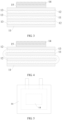
- FIG. 1 and FIG. 2 show examples of attaching the gas reducer to the battery cell.
- FIG. 1 shows a cell structure of a laminated battery
- FIG. 2 shows a cell structure of a wound battery.
- the gas reducer 14 is disposed on a side where the positive electrode plate 11 is located, so that the gas reducer 14 is in no contact with the negative electrode plate 12.
- FIG. 1 shows a cell structure of a laminated battery
- FIG. 2 shows a cell structure of a wound battery.
- the gas reducer 14 is disposed on a side where the positive electrode plate 11 is located, so that the gas reducer 14 is in
- FIG. 3 and FIG. 4 show another examples of attaching the gas reducer to the battery cell.
- FIG. 3 shows a cell structure of another laminated battery
- FIG. 4 shows a cell structure of another wound battery.
- the gas reducer 14 is disposed on a side where the negative electrode plate 12 is located, and an insulator 15 is disposed to make the gas reducer 14 be indirectly connected to the negative electrode plate 12, that is, be in non-electrical contact with the negative electrode plate 12.
- the gas reducer 14 In a manner of attaching the gas reducer 14 to the battery cell or to the inner wall of the battery housing, the gas reducer 14 is relatively fixed in the battery, and physical stability of the battery structure is improved.
- the gas reducer 14 may be attached to the battery cell and/or attached to the inner wall of the battery housing.
- the gas reducer 14 is optionally disposed on an electrode plate at an end of the battery cell. Further, an electrode active material of the electrode plate at the end is disposed on a surface, close to a separator 13, of a current collector; and the gas reducer 14 is disposed on a surface, away from the separator 13, of the current collector of the electrode plate at the end.
- the foregoing manners of attaching the gas reducer 14 allow the gas reducer 14 to be in proper contact with the gas produced in the battery.
- the positive electrode plate 11 is separated from the negative electrode plate 12 by the separator 13.
- the positive electrode plate 11 and the negative electrode plate 12 are stacked in sequence, and the positive electrode plate 11 located on the outermost side after lamination is the positive electrode plate 11 located at the end of the battery cell in this application.
- the positive electrode plate 11 and the negative electrode plate 12 are stacked in sequence and then wound, and the positive electrode plate 11 located on the outermost side at the end after winding is the positive electrode plate 11 located at the end of the battery cell in this application.
- the negative electrode plate 12 at an end of the battery cell can be determined by referring to the foregoing explanation, and details are not described herein again.
- the gas reducer 14 is disposed on a positive electrode current collector of the positive electrode plate 11, being electrically insulated from the negative electrode plate 12 properly.
- the gas reducer 14 is disposed on a positive electrode current collector of the positive electrode plate 11 at the end of the battery cell.
- the positive electrode current collector of the positive electrode plate 11 at the end of the battery cell has a first surface and a second surface that are opposite.
- the first surface is a surface of the positive electrode current collector close to the separator 13, and the first surface is provided with a positive-electrode material.
- the second surface is a surface of the positive electrode current collector away from the separator 13, and the gas reducer 14 is disposed on the second surface.
- the battery housing has only one accommodating cavity.
- the battery is a pouch battery, a prismatic battery, a button battery, or a cylindrical battery.
- the gas reducer 14 is attached to the inner wall of the housing, which encloses the accommodating cavity.
- the battery housing includes a battery cell compartment 16 and an air pocket compartment 17 that communicate with each other.
- the battery is a pouch battery, and the battery cell that has the positive electrode plate 11 and the negative electrode plate 12 is disposed in the battery cell compartment 16.
- the gas reducer 14 is disposed on the inner wall of the housing of the battery cell compartment 16 and/or the inner wall of the housing of the air pocket compartment 17.
- the shape of the gas reducer 14 is not limited, and, for example, the gas reducer 14 may be sheet-shaped, block-shaped, or granular. It can be understood that in the embodiment of this application the gas reducer 14 may be disposed in the battery based on the shape of the gas reducer 14. For example, under the condition that the gas reducer 14 is sheet-shaped, the gas reducer 14 is optionally attached to the battery cell and/or the inner wall of the battery housing; under the condition that the gas reducer 14 is block-shaped or granular, optionally the gas reducer 14 is movably disposed inside the battery housing.
- the gas reducer 14 can be fixedly disposed in the battery in a convenient manner of being attached to the battery cell and/or the inner wall of the battery housing.
- the gas reducer 14 may not be attached only to the battery cell structure or only to the inner wall of the battery housing, and the gas reducer 14 may be attached to both the inner wall of the battery housing and the battery cell.
- the gas reducer 14 may not be disposed only on the inner wall of the housing of the battery cell compartment 16 or attached only to the inner wall of the housing in the air pocket compartment 17, and the gas reducer 14 may be attached to both the inner wall of the housing of the battery cell compartment 16 and the inner wall of the housing of the air pocket compartment 17.
- the battery housing has only one accommodation cavity used as the battery cell compartment 16, and the sheet-shaped gas reducer 14 is attached to the battery cell or attached to the inner wall of the housing of the battery cell compartment 16.
- the sheet-shaped gas reducer 14 is attached to the battery cell.
- the battery housing includes the battery cell compartment 16 and the air pocket compartment 17 that communicate with each other, and the sheet-shaped gas reducer 14 is disposed both in the battery housing and the air pocket compartment 17.
- the sheet-shaped gas reducer 14 is attached to the inner wall of the housing of the air pocket compartment 17.
- the sheet-shaped gas reducer 14 is attached to the battery cell or attached to the inner wall of the housing of the battery cell compartment 16.
- the sheet-shaped gas reducer 14 is attached to the battery cell.
- the battery housing includes the battery cell compartment 16 and the air pocket compartment 17 that communicate with each other, and the sheet-shaped gas reducer 14 is disposed only in the air pocket compartment 17.
- the sheet-shaped gas reducer 14 is attached to the inner wall of the housing of the air pocket compartment 17.
- the gas reducer 14 is bound to the inner wall of the battery housing by using a binder.
- the gas reducer 14 is bound to the positive electrode current collector of the positive electrode plate 11 by using a binder, or the gas reducer 14 is formed on the positive electrode current collector of the positive electrode plate 11 in a roll-pressing manner. No binder is required in the roll-pressing manner, which simplifies disposition of the gas reducer 14.
- the sheet-shaped gas reducer 14 is disposed only on the positive electrode current collector of the positive electrode plate 11 at the end of the battery cell, and is formed on the second surface of the positive electrode current collector in a roll-pressing manner.
- the gas reducer 14 is block-shaped or granular
- the battery housing includes the battery cell compartment 16 and the air pocket compartment 17 that communicate with each other, and the gas reducer 14 is disposed only in the air pocket compartment 17, and the gas reducer 14 is movable in the air pocket compartment 17.
- a specific surface area of the gas reducer is also closely related to the battery cycling performance. Under the condition that the specific surface area of the gas reducer is excessively low, its active area for reaction will be small. This is not conducive to rapid absorption of the gas produced during battery cycling, and the passivated surface will further hinder the absorption of the gas reducer. Under the condition that the specific surface area of the gas reducer is excessively high, serious side reactions will occur between the gas reducer and the electrolyte. On the one hand, a large amount of the gas reducer will be consumed during surface passivation, and therefore the gas produced cannot be effectively absorbed. On the other hand, part of the electrolyte will also be consumed during the side reactions, significantly degrading the battery cycling performance.
- the specific surface area of the gas reducer is 5-100 square meters per gram (m 2 /g), optionally any point value of 5m 2 /g, 10m 2 /g, 20m 2 /g, 30m 2 /g, 40m 2 /g, 50m 2 /g, 60m 2 /g, 70m 2 /g, 80m 2 /g, 90m 2 /g, and 100m 2 /g or in a range between any two values thereof, for example, 20-50m 2 /g.
- a surface area of the gas reducer 14 will affect its passivation area and consumption in the non-aqueous electrolyte, and the surface area of the gas reducer 14 will affect the contact with and chemical consumption of the gas produced by the battery. Controlling the surface area of the gas reducer 14 to be a specified proportion in the battery can avoid excessive passivation and consumption of the gas reducer 14 and ensure that the gas reducer 14 can quickly react with and consume the gas produced by the battery.
- a proportion of the area of the sheet-shaped gas reducer 14 to a battery size is 35-45:60 or 38-42:60, for example, 50:60.
- the gas produced by the battery mainly derives from decomposition of the electrolyte. Therefore, in the battery using the non-aqueous electrolyte system in this application, a molar ratio of the gas reducer to the solvent of the non-aqueous electrolyte significantly affects the battery cycling performance.
- the gas reducer can be specified by adjusting the addition amount of the electrolyte. Under the condition that an amount of substance of the gas reducer is relatively small, due to low content of the gas reducer, the effect of absorbing the gas produced by the battery is limited, and therefore the battery cycling performance is not significantly improved. Under the condition that the amount of substance of the gas reducer is relatively larger, frequent side reactions will occur between such a large amount of reducer and the electrolyte, resulting in excessive loss of the electrolyte and thereby degrading the battery cycling performance.
- the amount of substance of the gas reducer is 1-10% of the amount of substance of the solvent of the non-aqueous electrolyte, optionally any point value of 1%, 2%, 3%, 4%, 5%, 6%, 7%, 8%, 9%, and 10% or in a range between any two values thereof, for example, 3-5%.
- an appropriate amount of the gas reducer 14 should be used. This helps ensure the gas to be fully absorbed by the battery through reaction when the battery is working, and avoids excessive consumption of the electrolyte due to passivation of the reducer.
- the batteries provided in this application may be assembled into a battery module.
- the battery module may include a plurality of such batteries, and a specific quantity may be adjusted based on application and capacity of the battery module.
- the foregoing battery modules may be further assembled into a battery pack, and a quantity of such battery modules included in the battery pack may be adjusted based on application and capacity of the battery pack.
- an embodiment of this application provides an apparatus, provided with the battery according to the embodiments of the first aspect.
- the battery supplies power for the apparatus.
- the apparatus may be, but is not limited to, a mobile communication terminal (for example, a mobile phone, a notebook computer, a tablet computer, a POS terminal, and an in-vehicle computer), an electric vehicle (for example, a battery electric vehicle, a hybrid electric vehicle, a plug-in hybrid electric vehicle, an electric bicycle, an electric scooter, an electric golf vehicle, or an electric truck), an electric train, a ship, a satellite, an energy storage system, and the like.
- a mobile communication terminal for example, a mobile phone, a notebook computer, a tablet computer, a POS terminal, and an in-vehicle computer
- an electric vehicle for example, a battery electric vehicle, a hybrid electric vehicle, a plug-in hybrid electric vehicle, an electric bicycle, an electric scooter, an electric golf vehicle, or an electric truck
- an electric train for example, a ship, a satellite, an energy storage system, and the like.
- the apparatus may be equipped with the battery provided in this application based on needs, or equipped with the battery module or the battery pack assembled from the batteries provided in this application.
- an embodiment of this application provides a method for curbing battery gassing.
- the method includes: disposing a gas reducer 14 inside a battery housing, where the gas reducer 14 is in no contact with or in non-electrical contact with a negative electrode plate 12; and the gas reducer 14 includes at least one of alkali metal and alkali metal alloy.
- the type of the battery the type of the gas reducer 14, and disposition of the gas reducer 14, refer to the embodiment provided in the first aspect. Details are not described herein again.
- a positive-electrode material is disposed on a first surface of a positive electrode current collector and the gas reducer 14 is disposed on a second surface to obtain a positive electrode plate 11; and the positive electrode plate 11 is disposed at an end of a battery cell.
- the gas reducer 14 is formed on the positive electrode current collector in a roll-pressing manner, so that the gas reducer 14 can be easily attached in the battery.
- the operation method and operation time for attaching the gas reducer 14 in the battery are not subject to particular limitations.
- a binder may also be used for binding.
- the operation time when a binder is used for binding, first electrode plates are stacked or wound into a battery cell, and then the gas reducer 14 is bound to the positive electrode current collector of the positive electrode plate 11; alternatively, first the gas reducer 14 is bound to the positive electrode current collector of the positive electrode plate 11, and then the electrode plates are stacked or wound into a battery cell.
- the housing to which the gas reducer 14 is attached, the housing on which the gas reducer 14 is movably disposed, the positive electrode plate 11 to which the gas reducer is attached, or the negative electrode plate 12 with which the gas reducer is in non-electrical connection is prepared first; the positive electrode plate 11, a separator 13, and the negative electrode plate 12 are assembled in sequence by using a method known in the art to obtain a battery cell; the battery cell is put into the housing; after drying, electrolyte is injected; and a battery is obtained after processes such as vacuum packaging, standing, formation, and shaping.
- the positive electrode plate 11, the separator 13, and the negative electrode plate 12 are assembled in sequence by using a method known in the art to obtain the battery cell; the gas reducer 14 is attached to an outer side of the positive electrode current collector of the positive electrode plate 11 at an end of the battery cell, or the gas reducer 14 is non-electrically connected to an outer side of a negative electrode current collector of the negative electrode plate 12 at an end of the cell through an insulator 15; the battery cell is put into the housing; after drying, electrolyte is injected; and the battery is obtained after processes such as vacuum packaging, standing, formation, and shaping.
- Each example and comparative example provide a battery, in which a positive electrode plate whose surface load is 4 milliampere hours per square centimeter (mAh cm -2 ) is paired with different types of negative electrode plates.
- Table 1 shows the positive-electrode material, the negative-electrode material, the battery packaging type, and disposition of the gas reducer of each battery. In the examples and comparative examples, if no air pocket is mentioned, it means no air pocket is configured.
- pouch batteries and prismatic batteries are laminated batteries with an overall size of 60cm 2 and an active area of 40cm 2 .
- the pouch batteries are model 4060D0 batteries
- the prismatic batteries are model 043048 batteries
- button batteries are model 2032 batteries
- cylindrical batteries are model 18650 batteries.
- the cycling performance of the battery provided by each example and comparative example was tested.
- the cycling performance is the number of cycles when the discharge capacity of the battery reaches 80% of the initial capacity, and the results are shown in Table 1.
- Test conditions The design capacity of the batteries was 140 milliampere hours (mAh), the test temperature was 25 degrees Celsius (°C), and three lithium-ion battery samples were taken for each embodiment and comparative example. Each lithium-ion battery was charged at a constant current of 1/3C from the initial voltage of the battery to 4.3 volts (V), charged at a constant voltage of 4.3V to a current of 0.05C, and then discharged at a constant current of 1/3C to 2.8V to complete a charge and discharge cycle. Charging and discharging were performed as such repeatedly. Table 1.
- Example 1 and Examples 9 to 13 it can be learned that in the embodiments of this application, under the condition that a specified gas reducer is provided in a battery using the non-aqueous electrolyte system, no matter which positive-electrode materials and negative-electrode materials are used, the gas reducer can chemically consume the gas produced by the battery and helps achieve good battery cycling performance.
- Example 1 and Examples 14 to 16 it can be learned that in the embodiments of this application, under the condition that a specified gas reducer is provided in a battery using the non-aqueous electrolyte system, no matter which packaging type is used, the gas reducer can chemically consume the gas produced by the battery and helps achieve good battery cycling performance.
- Example 1 and Examples 17 to 19 it can be learned that in the embodiments of this application, under the condition that a specified gas reducer is provided in a battery using the non-aqueous electrolyte system, no matter where the gas reducer is disposed inside the battery, the gas reducer can chemically consume the gas produced by the battery and helps achieve good battery cycling performance.
- Example 1 and Comparative Example 1 From comparison between Example 1 and Comparative Example 1, Example 2 and Comparative Example 2, and Example 12 and Comparative Example 3, it can be learned that in the embodiments of this application, under the condition that a specified type of gas reducer is provided for chemical consumption of gas produced, the battery cycling performance will be dramatically improved. It can be learned from comparison between Example 1 and Comparative Example 4 that the battery cycling performance will be dramatically improved by using a chemical consumption method of this application instead of a physical adsorption method.
- Example 1 Under the condition that a specified gas reducer is provided in a battery using the non-aqueous electrolyte system, the molar ratio of the gas reducer to the solvent of the non-aqueous electrolyte greatly affects the battery cycling performance.
- the battery cycling performance is improved dramatically when the molar ratio is 1-10%, especially 3-5%.
- the improvement on the battery cycling performance is not obvious compared with that in the example in which the molar ratio is 1-10%.
- the reason is that the amount of the gas reducer is small when the molar ratio is relatively low and effects of absorbing the gas produced by the battery are limited.
- the battery cycling performance obviously decreases compared with that in the example in which the molar ratio is 1-10%.
- the reason is that under the condition that the molar ratio is excessively high, frequent side reactions will occur between a large amount of reducer and the electrolyte and result in extra loss of the electrolyte.
- the specific surface area of the gas reducer is also closely related to the battery cycling performance.
- the battery cycling performance is improved dramatically when the specific surface area is 5-10m 2 /g, especially 20-50m 2 /g.
- the specific surface area is smaller than 5m 2 /g, the improvement on the battery cycling performance is not obvious compared with that in the example in which the specific surface area is 5-10m 2 /g. The reason is that the specific surface area of the gas reducer is excessively small and its active area for reaction is relatively small.
- Example 1 From comparison between Example 1 and Examples 33 to 35, it can be learned that in the embodiments of this application, under the condition that a specified gas reducer is provided in a battery using the non-aqueous electrolyte system, no matter which battery packaging type is used, the gas reducer can chemically consume the gas produced by the battery and helps achieve good battery cycling performance.
Landscapes
- Chemical & Material Sciences (AREA)
- Chemical Kinetics & Catalysis (AREA)
- Electrochemistry (AREA)
- General Chemical & Material Sciences (AREA)
- Engineering & Computer Science (AREA)
- Manufacturing & Machinery (AREA)
- Materials Engineering (AREA)
- Inorganic Chemistry (AREA)
- Composite Materials (AREA)
- Physics & Mathematics (AREA)
- Condensed Matter Physics & Semiconductors (AREA)
- General Physics & Mathematics (AREA)
- Secondary Cells (AREA)
Abstract
Description
- This application claims priority to
Chinese Patent Application No. 2021103654958, filed on April 6, 2021 - This application relates to the field of battery technologies, and in particular, to a battery, and a method and apparatus for curbing battery gassing.
- Secondary batteries have advantages such as long cycle life and environmental protection, and are widely applied in new energy industries. When a battery is working, a solid electrolyte film, formed on a surface of a negative electrode as a result of reduction by a non-aqueous electrolyte, partially decomposes to produce gas, and the non-aqueous electrolyte oxidizes on a surface of a positive electrode to also produce gas. On the one hand, these gases will lead to battery volume swelling, and flammable gases are included in these gases produced in the battery and cause safety risks to a certain extent. On the other hand, these gases dissolving in electrodes and the non-aqueous electrolyte will affect ion transmission and electron exchange in the non-aqueous electrolyte, degrading the cycling performance of the battery.
- In some cases, the following two methods are mainly used to solve the battery gassing problem.
- The first method is disposing a vent valve. When gas produced reaches a given amount, it is exhausted to an air pocket through the vent valve. However, the foregoing method will complicate the structure of a battery and cannot eliminate the produced gas in a timely manner.
- The second method is disposing a gas storage apparatus inside the battery, and the gas produced is absorbed and stored in the gas storage apparatus. In the foregoing method, however, an absorption medium with a specific size effect can absorb only a particular type of gas, and the amount of absorption and storage is relatively small.
- This application is intended to provide a battery, and a method and apparatus for curbing battery gassing. In this application, a gas reducer is used for chemical consumption of gas produced, which helps achieve simple configuration, no limitation from gas scale effect, timely degassing, and high degassing capacity.
- According to a first aspect, an embodiment of this application provides a battery, including a battery housing, a positive electrode plate, a negative electrode plate, and a non-aqueous electrolyte. A gas reducer is disposed inside the battery housing, the gas reducer includes at least one of alkali metal and alkali metal alloy, and the gas reducer is in no contact with or in non-electrical contact with the negative electrode plate.
- In the technical solution according to this embodiment of this application, the gas reducer is disposed inside the battery housing, which is easy to implement. Alkali metal and/or alkali metal alloy is selected as the gas reducer. The gas produced is reduced to an alkali metal salt relying on reducibility of the alkali metal and the alkali metal alloy, implementing chemical consumption of the gas. Such chemical consumption is not limited by gas size effect. In addition, because of strong reducibility of the alkali metal and the alkali metal alloy, multiple types of gas produced can be reduced in a quick and effective manner to achieve timely degassing and high degassing capacity.
- In some embodiments, an amount of substance of the gas reducer is 1-10% of an amount of substance of a solvent of the non-aqueous electrolyte, optionally 3-5%. In this design, a molar ratio of the gas reducer to the solvent of the non-aqueous electrolyte is controlled to be within a specified range. In this way, effects of absorbing gas produced by the battery are ensured, and frequent side reactions between excessive gas reducer and the electrolyte can be avoided.
- In some embodiments, a specific surface area of the gas reducer is 5-100m2/g, optionally 20-50m2/g. In this design, the specific surface area of the gas reducer is controlled to be within a specified range, ensuring that gas produced during battery cycling can be absorbed quickly, and avoiding a large specific surface area which causes serious side reactions between the gas reducer and the electrolyte.
- In some embodiments, the gas reducer is lithium metal or sodium metal. In this design, a specified type of gas reducer is selected. In this way, chemical consumption of multiple types of gas produced such as carbon monoxide, carbon dioxide, sulfur dioxide, sulfur trioxide, and nitrogen can be effectively implemented.
- In some embodiments, the gas reducer is disposed on a positive electrode current collector of the positive electrode plate. In this design, the gas reducer is disposed on the positive electrode current collector, so that the gas reducer can be electrically insulated from the negative electrode plate properly.
- In some embodiments, the positive electrode current collector of the positive electrode plate at an end of a battery cell has a first surface and a second surface that are opposite, a positive-electrode material is disposed on the first surface, and the gas reducer is disposed on the second surface. In this design, the gas reducer is disposed at the end of the battery cell, ensuring that the gas reducer can better contact and absorb the gas produced.
- In some embodiments, the gas reducer is disposed on an inner wall of the battery housing. In this design, the gas reducer is disposed on the inner wall of the battery housing. The gas reducer is relatively fixed in the battery and therefore physical stability of a battery structure is improved.
- In some embodiments, the battery housing includes a battery cell compartment and an air pocket compartment that communicate with each other, the positive electrode plate and the negative electrode plate are disposed in the battery cell compartment, and the gas reducer is disposed on the inner wall of the housing of the battery cell compartment and/or the inner wall of the housing of the air pocket compartment. In this design, the gas reducer is attached to the inner wall of the housing, so that the gas reducer is relatively fixed in the battery. Disposing the gas reducer in the air pocket compartment is convenient, allowing the gas reducer to be electrically insulated from the negative electrode plate properly.
- In some embodiments, the gas reducer is sheet-shaped. In this design, the gas reducer is sheet-shaped, so that it is easy to attach the gas reducer to the battery cell and the battery housing.
- In some embodiments, the battery is a pouch battery, a prismatic battery, a button battery, or a cylindrical battery.
- In some embodiments, the solvent of the non-aqueous electrolyte is a carbonate-based solvent, optionally a fluorocarbonate-based solvent. In this design, the solvent of the non-aqueous electrolyte is a carbonate-based solvent, and with a main component of CO2, gas produced by the electrolyte is highly active in reaction with the alkali metal gas reducer, ensuring that the gas reducer can better absorb the gas. When the non-aqueous electrolyte is a fluorocarbonate-based electrolyte, a more stable surface passivation layer can be formed on a surface of the alkali metal gas reducer, reducing side reactions between the gas reducer and the electrolyte.
- In some embodiments, the battery is a lithium-ion battery or a sodium-ion battery.
- In some embodiments, the positive-electrode material of the positive electrode plate is a ternary positive-electrode material, lithium iron phosphate, sodium iron phosphate, or lithium cobalt oxide, and/or a negative-electrode material of the negative electrode plate is lithium metal, sodium metal, or graphite.
- In some embodiments, the positive-electrode material of the battery is lithium nickel cobalt manganate or lithium nickel cobalt aluminate, and the negative-electrode material of the battery is lithium metal.
- According to a second aspect, an embodiment of this application provides an apparatus, provided with the battery according to the embodiments of the first aspect.
- According to a third aspect, an embodiment of this application provides a method for curbing battery gassing. The method includes: disposing a gas reducer inside a battery housing, where the gas reducer is in no contact with or in non-electrical contact with a negative electrode plate, and the gas reducer includes at least one of alkali metal and alkali metal alloy.
- In some embodiments, a positive-electrode material is disposed on a first surface of a positive electrode current collector and the gas reducer is disposed on a second surface to obtain a positive electrode plate; and the positive electrode plate is disposed at an end of a battery cell. In this design, the gas reducer is disposed on the positive electrode current collector, so that the gas reducer can be electrically insulated from the negative electrode plate properly.
- In some embodiments, the gas reducer is formed on the positive electrode current collector in a roll-pressing manner. In this design, the gas reducer is formed in a roll-pressing manner so that it can be attached easily.
- In order to describe the technical solutions in the embodiments of this application more clearly, the following briefly describes the accompanying drawings required for describing the embodiments. It should be appreciated that, the accompanying drawings below only show some embodiments of this application, and thus should not be considered as a limitation to the scope. A person of ordinary skill in the art may still derive other related drawings from the accompanying drawings without creative efforts.
-
FIG. 1 is a schematic diagram of a cell structure of the first type of laminated battery according to an embodiment of this application; -
FIG. 2 is a schematic diagram of a cell structure of the first type of wound battery according to an embodiment of this application; -
FIG. 3 is a schematic diagram of a cell structure of the second type of laminated battery according to an embodiment of this application; -
FIG. 4 is a schematic diagram of a cell structure of the second type of wound battery according to an embodiment of this application; -
FIG. 5 is a schematic structural diagram of a first type of battery according to an embodiment of this application; -
FIG. 6 is a schematic structural diagram of a second type of battery according to an embodiment of this application; -
FIG. 7 is a schematic structural diagram of a third type of battery according to an embodiment of this application; and -
FIG. 8 is a schematic structural diagram of a fourth type of battery according to an embodiment of this application. - 11: positive electrode plate; 12: negative electrode plate; 13: separator; 14: gas reducer; 15: insulator; 16: battery cell compartment; 17: air pocket compartment.
- To make the objectives, technical solutions, and advantages of embodiments of this application clearer, the following clearly and completely describes the technical solutions in the embodiments of this application. Embodiments, where specific conditions are not specified, are implemented in accordance with general conditions or those recommended by a manufacturer. The reagents or instruments used are all conventional products that can be purchased on the market if no manufacturer is indicated.
- It should be noted that "and/or" in this application may be explained in three ways. For example, "solution A and/or solution B", may be solution A alone, solution B alone, or solution A and solution B together.
- In addition, in the descriptions of this application, "a plurality of" means at least two.
- The following describes in detail the battery, and the method and apparatus for curbing battery gassing according to the embodiments of this application.
- A metal or an alloy with strong reducibility has strong chemical reactivity. When used in a battery, the metal or the alloy may react with the electrolyte directly and be consumed. Therefore, in some cases, generally a vent valve is used for degassing and a gas storage apparatus is used for gas storage, so as to eliminate gas in a physical manner. However, neither of the two foregoing methods can eliminate the produced gas. In addition, in a manner of using a gas storage apparatus to adsorb and store the gas produced, the gas storage apparatus generally needs to be separated from a non-aqueous electrolyte, so as to avoid corrosion and other impacts on the gas storage apparatus by the non-aqueous electrolyte.
- Researches found that alkali metal and alkali metal alloy have strong reducibility, and they can quickly and effectively reduce multiple types of gas produced in a battery and generate alkali metal salts. Although alkali metal and alkali metal alloy have strong chemical reactivity, a passivation layer will be formed on their surfaces when they are in the non-aqueous electrolyte. The passivation layer formed can prevent a further reaction between a gas reducer and the non-aqueous electrolyte, avoiding reaction consumption without affecting chemical consumption of gas by the gas reducer. Therefore, when alkali metal or alkali metal alloy is used as the gas reducer in a battery using a non-aqueous electrolyte, surfaces of the alkali metal and the alkali metal alloy can be passivated by the non-aqueous electrolyte for stable preservation, so that multiple types of gas produced in the battery can be chemically consumed quickly and effectively relying on strong reducibility of the alkali metal and the alkali metal alloy.
- According to a first aspect, an embodiment of this application provides a battery, including a battery housing, a positive electrode plate, a negative electrode plate, and a non-aqueous electrolyte. A gas reducer is disposed inside the battery housing, the gas reducer includes at least one of alkali metal and alkali metal alloy, and the gas reducer is in no contact with or in non-electrical contact with the negative electrode plate.
- In the embodiment of this application, the gas reducer only needs to be disposed in a position in no contact with or in non-electrical contact with the negative electrode plate, so as to ensure that strong reducibility of the gas reducer can be exerted. In addition, considering that the non-aqueous electrolyte can passivate the surface of the gas reducer, it is unnecessary to separate the gas reducer from the non-aqueous electrolyte. This simplifies battery structure configuration.
- During use of the battery, multiple types of gas produced in the battery can be chemically consumed quickly relying on the strong reducibility of the gas reducer. In addition, such chemical consumption allows a small amount of the gas reducer to consume a large amount of gas. On the one hand, battery volume swelling can be effectively relieved. On the other hand, the amount of produced gas dissolved at the electrodes and in the non-aqueous electrolyte can be reduced, improving ion transmission and electron exchange in the non-aqueous electrolyte and upgrading the cycling performance of the battery.
- By means of chemical reaction, the gas produced in the battery can be chemically eliminated, significantly improving safety performance of the battery. The gas reducer reduces the produced gas to alkali metal salts, without affecting the function of the non-aqueous electrolyte.
- Regarding the battery type: in this application, chemical consumption of gas can be performed effectively only if the gas reducer is disposed in a position in no contact with or in non-electrical contact with the negative electrode plate during battery configuration. Therefore, the battery is not specifically limited in terms of type (for example, the non-aqueous electrolyte system of the battery, packaging type of the battery, and electrochemical systems used by the electrodes of the battery) in the embodiment of this application, and can be selected from known batteries in this application as long as a non-aqueous electrolyte of the battery has the gas production problem.
- Batteries are categorized based on the non-aqueous electrolyte system. For example, the non-aqueous electrolyte of the battery may be not limited to ester-based non-aqueous electrolyte, ether-based non-aqueous electrolyte, or sulfone-based non-aqueous electrolyte.
- Through research, the inventors found that CO2 is a main component of gas produced by a carbonate-based electrolyte and CO2 is highly active in reaction with the alkali metal gas reducer. For example, the non-aqueous electrolyte of the battery uses a carbonate-based solvent, further improving battery cycling performance by the gas reducer greatly.
- Through further research, the inventors found that a more stable surface passivation layer can be formed on a surface of the alkali metal gas reducer when the non-aqueous electrolyte of the battery is a fluorocarbonate-based electrolyte. Furthermore, when the non-aqueous electrolyte of the battery uses a fluorocarbonate-based solvent, side reactions between the gas reducer and the electrolyte can be reduced, thereby dramatically improving the cycling performance of the battery.
- It should be noted that in this application, the ester-based electrolyte is a non-aqueous electrolyte that uses an ester-based solvent unsubstituted with fluorin, and the fluoroester-based electrolyte is a non-aqueous electrolyte that uses a fluoroester solvent.
- It can be understood that in the embodiment of this application, the electrolyte may include an organic solvent and an electrolyte salt dissolved in the organic solvent. The electrolyte salt is generally a lithium salt, for example, an inorganic lithium salt such as LiClO4, LiPF6, LiBF4, LiAsF6, and LiSbF6, or an organic lithium salt such as LiCF3SO3, LiCF3CO2, Li2C2F4 (SO3) 2, LiN (CF3SO2) 2, LiC (CF3SO2) 3, and LiCnF2n+1SO3 (n ≤ 2).
- When categorized based on the packaging type, the battery is, for example without limitation, a pouch battery, a prismatic battery, a button battery, or a cylindrical battery. For example, based on different disposition manners of electrode plates, the pouch battery or prismatic battery may be a laminated battery or a wound battery.
- When categorized based on the electrochemical system of the battery, the battery is, for example without limitation, a lithium-ion battery or a sodium-ion battery. Optionally, the positive-electrode material of the positive electrode plate is a ternary positive-electrode material, lithium iron phosphate, sodium iron phosphate, or lithium cobalt oxide, and a negative-electrode material of the negative electrode plate is lithium metal, sodium metal, or graphite.
- For example, the positive-electrode material of the battery is lithium nickel cobalt manganate or lithium nickel cobalt aluminate, and the negative-electrode material of the battery is lithium metal. The foregoing types of lithium-ion batteries feature high specific energy density, and research has revealed that using the alkali metal and alkali metal alloy as the gas reducer in the foregoing types of lithium-ion batteries can enhance gas consumption and therefore effectively improve the battery cycling performance.
- In the embodiment of this application, for example, the alkali metal may be lithium metal, sodium metal, potassium metal or rubidium metal, and the alkali metal alloy may be lithium silicon alloy, lithium aluminum alloy, lithium tin alloy, lithium boron alloy, lithium magnesium alloy, sodium antimony alloy, sodium phosphorus alloy, sodium bismuth alloy, sodium silicon alloy, potassium sodium alloy, lithium sodium alloy or lithium potassium alloy. The type of the gas reducer is not limited and can be selected based on the type of the gas produced by the battery. For example, the gas reducer may be one or at least two of the foregoing alkali metals and/or alkali metal alloys.
- For example, the gas reducer is lithium metal or sodium metal. In this case, the gas reducer can implement chemical consumption effectively on multiple types of gas produced in the battery such as carbon monoxide, carbon dioxide, sulfur dioxide, sulfur trioxide, and nitrogen.
- In different battery systems, gas production differs due to impact from factors such as the non-aqueous electrolyte system and the electrochemical systems of electrodes. In addition, different gas reducers have different gas consumption effects. A specific combination of the non-aqueous electrolyte system, the electrochemical system of the electrodes and the type of gas reducer can ensure adequate chemical consumption of the gas produced.
- For example, the positive-electrode material is lithium nickel cobalt manganate, the gas reducer is one or more of alkali metal (for example, lithium metal, sodium metal, or potassium metal) or alkali metal alloy (for example, lithium magnesium alloy or sodium tin alloy), and the non-aqueous electrolyte is ester-based non-aqueous electrolyte, ether-based non-aqueous electrolyte, or sulfone-based non-aqueous electrolyte.
- For another example, the positive-electrode material is lithium iron phosphate, lithium cobaltate or sodium iron phosphate, or lithium nickel cobalt aluminate, the gas reducer is alkali metal (for example, lithium metal, sodium metal, or potassium metal), and the non-aqueous electrolyte is ester-based non-aqueous electrolyte.
- In the embodiment of this application, the position where the gas reducer is disposed is not limited as long as it is in contact with the gas produced in the battery and it is in no contact with or in non-electrical contact with the negative electrode plate. It should be noted that in the embodiment of this application: considering that the non-aqueous electrolyte can passivate the surface of the gas reducer specified in this application, it is unnecessary to separate the gas reducer from the non-aqueous electrolyte. This means that it is not mandatory to separate the gas reducer from the non-aqueous electrolyte. It can be understood that for the battery according to this application, the manner of disposing the gas reducer is not limited to making the gas reducer be in contact with the non-aqueous electrolyte. For example, the gas reducer may alternatively be enclosed in a separation chamber through which gas can pass but the electrolyte cannot.
- In implementations of the gas reducer being directly disposed in the battery, for example, the gas reducer is attached to a battery cell, or attached to an inner wall of the battery housing, or is movably disposed inside the battery housing. In a manner of the gas reducer being attached to the inner wall of the battery housing or being movably disposed inside the battery housing, the gas reducer is in no contact with the negative electrode plate.
FIG. 1 and FIG. 2 show examples of attaching the gas reducer to the battery cell.FIG. 1 shows a cell structure of a laminated battery, andFIG. 2 shows a cell structure of a wound battery. Thegas reducer 14 is disposed on a side where thepositive electrode plate 11 is located, so that thegas reducer 14 is in no contact with thenegative electrode plate 12.FIG. 3 and FIG. 4 show another examples of attaching the gas reducer to the battery cell.FIG. 3 shows a cell structure of another laminated battery, andFIG. 4 shows a cell structure of another wound battery. Thegas reducer 14 is disposed on a side where thenegative electrode plate 12 is located, and aninsulator 15 is disposed to make thegas reducer 14 be indirectly connected to thenegative electrode plate 12, that is, be in non-electrical contact with thenegative electrode plate 12. - In a manner of attaching the
gas reducer 14 to the battery cell or to the inner wall of the battery housing, thegas reducer 14 is relatively fixed in the battery, and physical stability of the battery structure is improved. Optionally, thegas reducer 14 may be attached to the battery cell and/or attached to the inner wall of the battery housing. - In a manner of attaching the
gas reducer 14 to the battery cell, thegas reducer 14 is optionally disposed on an electrode plate at an end of the battery cell. Further, an electrode active material of the electrode plate at the end is disposed on a surface, close to aseparator 13, of a current collector; and thegas reducer 14 is disposed on a surface, away from theseparator 13, of the current collector of the electrode plate at the end. The foregoing manners of attaching thegas reducer 14 allow thegas reducer 14 to be in proper contact with the gas produced in the battery. - It should be noted that in the battery cell, the
positive electrode plate 11 is separated from thenegative electrode plate 12 by theseparator 13. Regarding thepositive electrode plate 11 at an end of the battery in this application: as shown inFIG. 1 andFIG. 3 , in the laminated battery, thepositive electrode plate 11 and thenegative electrode plate 12 are stacked in sequence, and thepositive electrode plate 11 located on the outermost side after lamination is thepositive electrode plate 11 located at the end of the battery cell in this application. As shown inFIG. 2 andFIG. 4 , in the wound battery, thepositive electrode plate 11 and thenegative electrode plate 12 are stacked in sequence and then wound, and thepositive electrode plate 11 located on the outermost side at the end after winding is thepositive electrode plate 11 located at the end of the battery cell in this application. Likewise, thenegative electrode plate 12 at an end of the battery cell can be determined by referring to the foregoing explanation, and details are not described herein again. - As shown in
FIG. 1 and FIG. 2 , for example, thegas reducer 14 is disposed on a positive electrode current collector of thepositive electrode plate 11, being electrically insulated from thenegative electrode plate 12 properly. Optionally, thegas reducer 14 is disposed on a positive electrode current collector of thepositive electrode plate 11 at the end of the battery cell. - For example, the positive electrode current collector of the
positive electrode plate 11 at the end of the battery cell has a first surface and a second surface that are opposite. The first surface is a surface of the positive electrode current collector close to theseparator 13, and the first surface is provided with a positive-electrode material. The second surface is a surface of the positive electrode current collector away from theseparator 13, and thegas reducer 14 is disposed on the second surface. - In a manner of the
gas reducer 14 being attached to the inner wall of the battery housing, in an example implementation, the battery housing has only one accommodating cavity. For example, the battery is a pouch battery, a prismatic battery, a button battery, or a cylindrical battery. In this manner of disposition, thegas reducer 14 is attached to the inner wall of the housing, which encloses the accommodating cavity. In a second example implementation, the battery housing includes abattery cell compartment 16 and anair pocket compartment 17 that communicate with each other. For example, the battery is a pouch battery, and the battery cell that has thepositive electrode plate 11 and thenegative electrode plate 12 is disposed in thebattery cell compartment 16. In this manner of disposition, thegas reducer 14 is disposed on the inner wall of the housing of thebattery cell compartment 16 and/or the inner wall of the housing of theair pocket compartment 17. - In the embodiment of this application, the shape of the
gas reducer 14 is not limited, and, for example, thegas reducer 14 may be sheet-shaped, block-shaped, or granular. It can be understood that in the embodiment of this application thegas reducer 14 may be disposed in the battery based on the shape of thegas reducer 14. For example, under the condition that thegas reducer 14 is sheet-shaped, thegas reducer 14 is optionally attached to the battery cell and/or the inner wall of the battery housing; under the condition that thegas reducer 14 is block-shaped or granular, optionally thegas reducer 14 is movably disposed inside the battery housing. - For example, under the condition that the
gas reducer 14 is sheet-shaped, thegas reducer 14 can be fixedly disposed in the battery in a convenient manner of being attached to the battery cell and/or the inner wall of the battery housing. - In the implementation in which the sheet-shaped
gas reducer 14 is attached to the battery cell and/or the inner wall of the battery housing, thegas reducer 14 may not be attached only to the battery cell structure or only to the inner wall of the battery housing, and thegas reducer 14 may be attached to both the inner wall of the battery housing and the battery cell. In the implementation in which thegas reducer 14 is disposed on the inner wall of the housing, thegas reducer 14 may not be disposed only on the inner wall of the housing of thebattery cell compartment 16 or attached only to the inner wall of the housing in theair pocket compartment 17, and thegas reducer 14 may be attached to both the inner wall of the housing of thebattery cell compartment 16 and the inner wall of the housing of theair pocket compartment 17. - Referring to
FIG. 5 , for example, the battery housing has only one accommodation cavity used as thebattery cell compartment 16, and the sheet-shapedgas reducer 14 is attached to the battery cell or attached to the inner wall of the housing of thebattery cell compartment 16. For example, the sheet-shapedgas reducer 14 is attached to the battery cell. - Referring to
FIG. 6 , for another example, the battery housing includes thebattery cell compartment 16 and theair pocket compartment 17 that communicate with each other, and the sheet-shapedgas reducer 14 is disposed both in the battery housing and theair pocket compartment 17. In theair pocket compartment 17, the sheet-shapedgas reducer 14 is attached to the inner wall of the housing of theair pocket compartment 17. In thebattery cell compartment 16, the sheet-shapedgas reducer 14 is attached to the battery cell or attached to the inner wall of the housing of thebattery cell compartment 16. For example, the sheet-shapedgas reducer 14 is attached to the battery cell. - Referring to
FIG. 7 , for still another example, the battery housing includes thebattery cell compartment 16 and theair pocket compartment 17 that communicate with each other, and the sheet-shapedgas reducer 14 is disposed only in theair pocket compartment 17. In theair pocket compartment 17, the sheet-shapedgas reducer 14 is attached to the inner wall of the housing of theair pocket compartment 17. - In a manner of the
gas reducer 14 being attached to the inner wall of the battery housing, optionally thegas reducer 14 is bound to the inner wall of the battery housing by using a binder. In a manner of thegas reducer 14 being attached to the battery cell, optionally, thegas reducer 14 is bound to the positive electrode current collector of thepositive electrode plate 11 by using a binder, or thegas reducer 14 is formed on the positive electrode current collector of thepositive electrode plate 11 in a roll-pressing manner. No binder is required in the roll-pressing manner, which simplifies disposition of thegas reducer 14. - In some example implementations, the sheet-shaped
gas reducer 14 is disposed only on the positive electrode current collector of thepositive electrode plate 11 at the end of the battery cell, and is formed on the second surface of the positive electrode current collector in a roll-pressing manner. - In an implementation in which the block-shaped or
granular gas reducer 14 is movably disposed in the battery housing, referring toFIG. 8 , for still another example, thegas reducer 14 is block-shaped or granular, the battery housing includes thebattery cell compartment 16 and theair pocket compartment 17 that communicate with each other, and thegas reducer 14 is disposed only in theair pocket compartment 17, and thegas reducer 14 is movable in theair pocket compartment 17. - The inventors also found that, for the battery using the non-aqueous electrolyte system of this application, a specific surface area of the gas reducer is also closely related to the battery cycling performance. Under the condition that the specific surface area of the gas reducer is excessively low, its active area for reaction will be small. This is not conducive to rapid absorption of the gas produced during battery cycling, and the passivated surface will further hinder the absorption of the gas reducer. Under the condition that the specific surface area of the gas reducer is excessively high, serious side reactions will occur between the gas reducer and the electrolyte. On the one hand, a large amount of the gas reducer will be consumed during surface passivation, and therefore the gas produced cannot be effectively absorbed. On the other hand, part of the electrolyte will also be consumed during the side reactions, significantly degrading the battery cycling performance.
- For example, the specific surface area of the gas reducer is 5-100 square meters per gram (m2/g), optionally any point value of 5m2/g, 10m2/g, 20m2/g, 30m2/g, 40m2/g, 50m2/g, 60m2/g, 70m2/g, 80m2/g, 90m2/g, and 100m2/g or in a range between any two values thereof, for example, 20-50m2/g.
- In the foregoing technical solution, a surface area of the
gas reducer 14 will affect its passivation area and consumption in the non-aqueous electrolyte, and the surface area of thegas reducer 14 will affect the contact with and chemical consumption of the gas produced by the battery. Controlling the surface area of thegas reducer 14 to be a specified proportion in the battery can avoid excessive passivation and consumption of thegas reducer 14 and ensure that thegas reducer 14 can quickly react with and consume the gas produced by the battery. - In some example implementations, for example, in a manner of the sheet-shaped
gas reducer 14 being disposed only on the positive electrode current collector of thepositive electrode plate 11 at the end of the battery cell, a proportion of the area of the sheet-shapedgas reducer 14 to a battery size (an area of one side of the current collector) is 35-45:60 or 38-42:60, for example, 50:60. - Further, the inventors found that the gas produced by the battery mainly derives from decomposition of the electrolyte. Therefore, in the battery using the non-aqueous electrolyte system in this application, a molar ratio of the gas reducer to the solvent of the non-aqueous electrolyte significantly affects the battery cycling performance. In view of this, the gas reducer can be specified by adjusting the addition amount of the electrolyte. Under the condition that an amount of substance of the gas reducer is relatively small, due to low content of the gas reducer, the effect of absorbing the gas produced by the battery is limited, and therefore the battery cycling performance is not significantly improved. Under the condition that the amount of substance of the gas reducer is relatively larger, frequent side reactions will occur between such a large amount of reducer and the electrolyte, resulting in excessive loss of the electrolyte and thereby degrading the battery cycling performance.
- For example, the amount of substance of the gas reducer is 1-10% of the amount of substance of the solvent of the non-aqueous electrolyte, optionally any point value of 1%, 2%, 3%, 4%, 5%, 6%, 7%, 8%, 9%, and 10% or in a range between any two values thereof, for example, 3-5%.
- In the foregoing technical solution, considering impact of the amount of the
gas reducer 14 on a total amount of gas consumed, an appropriate amount of thegas reducer 14 should be used. This helps ensure the gas to be fully absorbed by the battery through reaction when the battery is working, and avoids excessive consumption of the electrolyte due to passivation of the reducer. - In some embodiments, the batteries provided in this application may be assembled into a battery module. The battery module may include a plurality of such batteries, and a specific quantity may be adjusted based on application and capacity of the battery module.
- The foregoing battery modules may be further assembled into a battery pack, and a quantity of such battery modules included in the battery pack may be adjusted based on application and capacity of the battery pack.
- According to a second aspect, an embodiment of this application provides an apparatus, provided with the battery according to the embodiments of the first aspect. The battery supplies power for the apparatus.
- In the embodiment of this application, the apparatus may be, but is not limited to, a mobile communication terminal (for example, a mobile phone, a notebook computer, a tablet computer, a POS terminal, and an in-vehicle computer), an electric vehicle (for example, a battery electric vehicle, a hybrid electric vehicle, a plug-in hybrid electric vehicle, an electric bicycle, an electric scooter, an electric golf vehicle, or an electric truck), an electric train, a ship, a satellite, an energy storage system, and the like.
- It can be understood that the apparatus may be equipped with the battery provided in this application based on needs, or equipped with the battery module or the battery pack assembled from the batteries provided in this application.
- According to a third aspect, an embodiment of this application provides a method for curbing battery gassing. The method includes: disposing a
gas reducer 14 inside a battery housing, where thegas reducer 14 is in no contact with or in non-electrical contact with anegative electrode plate 12; and thegas reducer 14 includes at least one of alkali metal and alkali metal alloy. Regarding the type of the battery, the type of thegas reducer 14, and disposition of thegas reducer 14, refer to the embodiment provided in the first aspect. Details are not described herein again. - For example, a positive-electrode material is disposed on a first surface of a positive electrode current collector and the
gas reducer 14 is disposed on a second surface to obtain apositive electrode plate 11; and thepositive electrode plate 11 is disposed at an end of a battery cell. Optionally, in the foregoing implementation, thegas reducer 14 is formed on the positive electrode current collector in a roll-pressing manner, so that thegas reducer 14 can be easily attached in the battery. - It can be understood that in the embodiment of this application, the operation method and operation time for attaching the
gas reducer 14 in the battery are not subject to particular limitations. Regarding the operation method, apart from the rolling-pressing manner, a binder may also be used for binding. Regarding the operation time, when a binder is used for binding, first electrode plates are stacked or wound into a battery cell, and then thegas reducer 14 is bound to the positive electrode current collector of thepositive electrode plate 11; alternatively, first thegas reducer 14 is bound to the positive electrode current collector of thepositive electrode plate 11, and then the electrode plates are stacked or wound into a battery cell. - In a preparation method of the battery according to this application, the housing to which the
gas reducer 14 is attached, the housing on which thegas reducer 14 is movably disposed, thepositive electrode plate 11 to which the gas reducer is attached, or thenegative electrode plate 12 with which the gas reducer is in non-electrical connection is prepared first; thepositive electrode plate 11, aseparator 13, and thenegative electrode plate 12 are assembled in sequence by using a method known in the art to obtain a battery cell; the battery cell is put into the housing; after drying, electrolyte is injected; and a battery is obtained after processes such as vacuum packaging, standing, formation, and shaping. - In a preparation method of the battery according to this application, the
positive electrode plate 11, theseparator 13, and thenegative electrode plate 12 are assembled in sequence by using a method known in the art to obtain the battery cell; thegas reducer 14 is attached to an outer side of the positive electrode current collector of thepositive electrode plate 11 at an end of the battery cell, or thegas reducer 14 is non-electrically connected to an outer side of a negative electrode current collector of thenegative electrode plate 12 at an end of the cell through aninsulator 15; the battery cell is put into the housing; after drying, electrolyte is injected; and the battery is obtained after processes such as vacuum packaging, standing, formation, and shaping. - The following further describes in detail this application in terms of characteristics and performance with reference to the embodiments.
- Each example and comparative example provide a battery, in which a positive electrode plate whose surface load is 4 milliampere hours per square centimeter (mAh cm-2) is paired with different types of negative electrode plates.
- Table 1 shows the positive-electrode material, the negative-electrode material, the battery packaging type, and disposition of the gas reducer of each battery. In the examples and comparative examples, if no air pocket is mentioned, it means no air pocket is configured.
- In the examples and comparative examples, pouch batteries and prismatic batteries are laminated batteries with an overall size of 60cm2 and an active area of 40cm2. The pouch batteries are model 4060D0 batteries, the prismatic batteries are model 043048 batteries, button batteries are model 2032 batteries, and cylindrical batteries are model 18650 batteries.
- The cycling performance of the battery provided by each example and comparative example was tested. The cycling performance is the number of cycles when the discharge capacity of the battery reaches 80% of the initial capacity, and the results are shown in Table 1.
- Test conditions: The design capacity of the batteries was 140 milliampere hours (mAh), the test temperature was 25 degrees Celsius (°C), and three lithium-ion battery samples were taken for each embodiment and comparative example. Each lithium-ion battery was charged at a constant current of 1/3C from the initial voltage of the battery to 4.3 volts (V), charged at a constant voltage of 4.3V to a current of 0.05C, and then discharged at a constant current of 1/3C to 2.8V to complete a charge and discharge cycle. Charging and discharging were performed as such repeatedly.
Table 1. Battery structures and test results Positive-electrode material Negative-electrode material Type of non-aqueous electrolyte Battery packaging type Gas reducer Cycling performance Position Type and form Molar ratio (%) Specific surface area (m2/g) Example 1 Lithium nickel cobalt manganate Lithium metal Ester-based non-aqueous electrolyte Pouch battery Inner wall of battery Lithium sheet 1 5 158 Example 2 Lithium nickel cobalt aluminate Lithium metal Ester-based non-aqueous electrolyte Pouch battery Inner wall of battery Lithium sheet 1 5 154 Example 3 Lithium nickel cobalt manganate Lithium metal Ester-based non-aqueous electrolyte Pouch battery Inner wall of battery Sodium sheet 1 5 156 Example 4 Lithium nickel cobalt aluminate Lithium metal Ester-based non-aqueous electrolyte Pouch battery Inner wall of battery Sodium sheet 1 5 155 Example 5 Lithium nickel cobalt manganate Lithium metal Ester-based non-aqueous electrolyte Pouch battery Inner wall of battery Potassium sheet 1 5 156 Example 6 Lithium nickel cobalt aluminate Lithium metal Ester-based non-aqueous electrolyte Pouch battery Inner wall of battery Potassium sheet 1 5 159 Example 7 Lithium nickel cobalt manganate Lithium metal Ester-based non-aqueous electrolyte Pouch battery Inner wall of battery Lithium magnesium alloy 1 5 161 Example 8 Lithium nickel cobalt aluminate Lithium metal Ester-based non-aqueous electrolyte Pouch battery Inner wall of battery Sodium tin alloy 1 5 160 Example 9 Lithium iron phosphate Lithium metal Ester-based non-aqueous electrolyte Pouch battery Inner wall of battery Lithium sheet 1 5 223 Example 10 Lithium cobaltate Lithium metal Ester-based non-aqueous electrolyte Pouch battery Inner wall of battery Lithium sheet 1 5 157 Example 11 Sodium iron phosphate Sodium metal Ester-based non-aqueous electrolyte Pouch battery Inner wall of battery Lithium sheet 1 5 143 Example 12 Lithium nickel cobalt manganate Graphite Ester-based non-aqueous electrolyte Pouch battery Inner wall of battery Lithium sheet 1 5 865 Example 13 Lithium nickel cobalt aluminate Graphite Ester-based non-aqueous electrolyte Pouch battery Inner wall of battery Lithium sheet 1 5 860 Example 14 Lithium nickel cobalt manganate Lithium metal Ester-based non-aqueous electrolyte Button battery Inner wall of battery Lithium sheet 1 5 200 Example 15 Lithium nickel cobalt manganate Lithium metal Ester-based non-aqueous electrolyte Cylindrical battery Inner wall of battery Lithium sheet 1 5 165 Example 16 Lithium nickel cobalt manganate Lithium metal Ester-based non-aqueous electrolyte Prismatic battery Inner wall of battery Lithium sheet 1 5 162 Example 17 Lithium nickel cobalt manganate Lithium metal Ester-based non-aqueous electrolyte Pouch battery Positive electrode current collector Lithium sheet 1 5 159 Example 18 Lithium nickel cobalt manganate Lithium metal Ester-based non-aqueous electrolyte Pouch battery Air pocket Lithium sheet 1 5 158 Example 19 Lithium nickel cobalt manganate Lithium metal Ester-based non-aqueous electrolyte Pouch battery Positive electrode current collector Lithium sheet 1 5 245 Example 20 Lithium nickel cobalt manganate Lithium metal Ether-based non-aqueous electrolyte Pouch battery Inner wall of battery Lithium sheet 1 5 148 Example 21 Lithium nickel cobalt manganate Lithium metal Highly enriched sulfone-based non-aqueous electrolyte Pouch battery Inner wall of battery Lithium sheet 1 5 136 Example 22 Lithium nickel cobalt manganate Lithium metal Fluoroester-based non-aqueous electrolyte Pouch battery Inner wall of battery Lithium sheet 1 5 284 Example 23 Lithium nickel cobalt manganate Lithium metal Ester-based non-aqueous electrolyte Pouch battery Inner wall of battery Lithium sheet 0.2 5 100 Example 24 Lithium nickel cobalt manganate Lithium metal Ester-based non-aqueous electrolyte Pouch battery Inner wall of battery Lithium sheet 3 5 179 Example 25 Lithium nickel cobalt manganate Lithium metal Ester-based non-aqueous electrolyte Pouch battery Inner wall of battery Lithium sheet 5 5 184 Example 26 Lithium nickel cobalt manganate Lithium metal Ester-based non-aqueous electrolyte Pouch battery Inner wall of battery Lithium sheet 10 5 150 Example 27 Lithium nickel cobalt manganate Lithium metal Ester-based non-aqueous electrolyte Pouch battery Inner wall of battery Lithium sheet 20 5 126 Example 28 Lithium nickel cobalt manganate Lithium metal Ester-based non-aqueous electrolyte Pouch battery Inner wall of battery Lithium sheet 1 1 115 Example 29 Lithium nickel cobalt manganate Lithium metal Ester-based non-aqueous electrolyte Pouch battery Inner wall of battery Lithium sheet 1 20 171 Example 30 Lithium nickel cobalt manganate Lithium metal Ester-based non-aqueous electrolyte Pouch battery Inner wall of battery Lithium sheet 1 50 166 Example 31 Lithium nickel cobalt manganate Lithium metal Ester-based non-aqueous electrolyte Pouch battery Inner wall of battery Lithium sheet 1 100 148 Example 32 Lithium nickel cobalt manganate Lithium metal Ester-based non-aqueous electrolyte Pouch battery Inner wall of battery Lithium sheet 1 200 103 Example 33 Lithium nickel cobalt manganate Lithium metal Ester-based non-aqueous electrolyte Prismatic battery Inner wall of battery Lithium sheet 1 5 160 Example 34 Lithium nickel cobalt manganate Lithium metal Ester-based non-aqueous electrolyte Button battery Inner wall of battery Lithium sheet 1 5 165 Example 35 Lithium nickel cobalt manganate Lithium metal Ester-based non-aqueous electrolyte Cylindrical battery Inner wall of battery Lithium sheet 1 5 157 Comparative example 1 Lithium nickel cobalt manganate Lithium metal Ester-based non-aqueous electrolyte Pouch battery Not applicable Not applicable Not applicable Not applicable 96 Comparative example 2 Lithium nickel cobalt aluminate Lithium metal Ester-based non-aqueous electrolyte Pouch battery Not applicable Not applicable Not applicable Not applicable 91 Comparative example 3 Lithium nickel cobalt manganate Graphite Ester-based non-aqueous electrolyte Pouch battery Not applicable Not applicable Not applicable Not applicable 532 Comparative example 4 Lithium nickel cobalt manganate Lithium metal Ester-based non-aqueous electrolyte Pouch battery Inner wall of battery Molecular sieve Not applicable 300 106 Comparative example 5 Lithium nickel cobalt manganate Lithium metal Ether-based non-aqueous electrolyte Pouch battery Inner wall of battery Not applicable Not applicable Not applicable 125 Comparative example 6 Lithium nickel cobalt manganate Lithium metal Highly enriched sulfone-based non-aqueous electrolyte Pouch battery Inner wall of battery Not applicable Not applicable Not applicable 101 Comparative example 7 Lithium nickel cobalt manganate Lithium metal Fluoroester-based non-aqueous electrolyte Pouch battery Inner wall of battery Not applicable Not applicable Not applicable 176 -
- (1) The electrolytes of the same type in all examples and comparative examples in Table 1 are the same electrolyte.
The ester-based non-aqueous electrolyte is a non-aqueous electrolyte that uses a carbonate-based solvent unsubstituted with fluorin, specifically ethylene carbonate containing 1 mol/L of lithium bisfluorosulfonimide. The fluoroester-based non-aqueous electrolyte is a non-aqueous electrolyte that use a fluorocarbonate-based solvent, specifically fluoroethylene carbonate containing 1 mole per liter (mol/L) of lithium bisfluorosulfonimide. The ether-based non-aqueous electrolyte is specifically ethylene glycol dimethyl ether containing 1 mol/L of lithium bisfluorosulfonimide, and the highly enriched sulfone-based non-aqueous electrolyte is specifically ethylene glycol dimethyl ether containing 3 mol/L of lithium bisfluorosulfonimide. - (2) The molar ratio of the gas reducer in Table 1 is a percentage of the amount of substance of the gas reducer relative to the amount of substance of the solvent of the non-aqueous electrolyte, that is, the molar ratio of the gas reducer = (the amount of substance of the gas reducer/the amount of substance of the solvent of the non-aqueous electrolyte)∗100%.
- According to Examples 1 to 8, it can be learned that in the embodiments of this application, different alkali metals and alkali metal alloys used as the gas reducer can all chemically consume the gas produced by a battery and help achieve good battery cycling performance.
- According to Example 1 and Examples 9 to 13, it can be learned that in the embodiments of this application, under the condition that a specified gas reducer is provided in a battery using the non-aqueous electrolyte system, no matter which positive-electrode materials and negative-electrode materials are used, the gas reducer can chemically consume the gas produced by the battery and helps achieve good battery cycling performance.
- According to Example 1 and Examples 14 to 16, it can be learned that in the embodiments of this application, under the condition that a specified gas reducer is provided in a battery using the non-aqueous electrolyte system, no matter which packaging type is used, the gas reducer can chemically consume the gas produced by the battery and helps achieve good battery cycling performance.
- According to Example 1 and Examples 17 to 19, it can be learned that in the embodiments of this application, under the condition that a specified gas reducer is provided in a battery using the non-aqueous electrolyte system, no matter where the gas reducer is disposed inside the battery, the gas reducer can chemically consume the gas produced by the battery and helps achieve good battery cycling performance.
- From comparison between Example 1 and Comparative Example 1, Example 2 and Comparative Example 2, and Example 12 and Comparative Example 3, it can be learned that in the embodiments of this application, under the condition that a specified type of gas reducer is provided for chemical consumption of gas produced, the battery cycling performance will be dramatically improved. It can be learned from comparison between Example 1 and Comparative Example 4 that the battery cycling performance will be dramatically improved by using a chemical consumption method of this application instead of a physical adsorption method.
- According to Examples 20 to 22 and Comparative Examples 5 to 7, it can be learned that in the embodiments of this application, under the condition that a specified gas reducer is provided in a battery using the non-aqueous electrolyte system and different non-aqueous electrolytes are used, the gas reducer can chemically consume the gas produced by the battery and helps achieve good battery cycling performance.
- From comparison between Example 1 and Comparative Example 1 and comparison between Examples 20 to 22 and Comparative Examples 5 to 7, it can be learned that after using a gas consuming medium, the battery using the ester-based electrolyte has a much better improvement on the cycling performance than the battery using the ether-based electrolyte or the sulfone-based electrolyte. This is because that a dominant component of gas produced by an ester-based electrolyte is CO2 which is highly active in reaction with the alkali metal gas reducer, and therefore the cycling performance is improved more dramatically. Further, the battery using the fluoroester-based electrolyte has a much better improvement on the cycling performance than the battery using the ester-based electrolyte. This is because that a more stable surface passivation layer can be formed on the alkali metal gas reducer in the fluoroester-based electrolyte and the side reactions between the reducer and the electrolyte are reduced, thereby further dramatically improving the battery performance.
- It can be learned from comparison between Example 1 and Examples 23 to 27 that in the embodiments of this application, under the condition that a specified gas reducer is provided in a battery using the non-aqueous electrolyte system, the molar ratio of the gas reducer to the solvent of the non-aqueous electrolyte greatly affects the battery cycling performance. The battery cycling performance is improved dramatically when the molar ratio is 1-10%, especially 3-5%. Under the condition that the molar ratio is lower than 1%, the improvement on the battery cycling performance is not obvious compared with that in the example in which the molar ratio is 1-10%. The reason is that the amount of the gas reducer is small when the molar ratio is relatively low and effects of absorbing the gas produced by the battery are limited. Under the condition that the molar ratio is higher than 10%, the battery cycling performance obviously decreases compared with that in the example in which the molar ratio is 1-10%. The reason is that under the condition that the molar ratio is excessively high, frequent side reactions will occur between a large amount of reducer and the electrolyte and result in extra loss of the electrolyte.
- It can be learned from comparison between Example 1 and Examples 28 to 32 that in the embodiments of this application, under the condition that a specified gas reducer is provided in a battery using the non-aqueous electrolyte system, the specific surface area of the gas reducer is also closely related to the battery cycling performance. The battery cycling performance is improved dramatically when the specific surface area is 5-10m2/g, especially 20-50m2/g. Under the condition that the specific surface area is smaller than 5m2/g, the improvement on the battery cycling performance is not obvious compared with that in the example in which the specific surface area is 5-10m2/g. The reason is that the specific surface area of the gas reducer is excessively small and its active area for reaction is relatively small. This is not conducive to rapid absorption of the gas produced during battery cycling, and the passivated surface will further hinder the absorption of the reducer. Under the condition that the specific surface area is larger than 50m2/g, the battery cycling performance decreases compared with that in the example in which the specific surface area is 20-50m2/g, and especially under the condition that the specific surface area is larger than 100m2/g, the battery cycling performance decreases more obviously compared with that in the example in which the specific surface area is 20-50m2/g. The reason is that serious side reactions will occur between the gas reducer and the electrolyte because the specific surface area is excessively large. On the one hand, a larger amount of reducer will be consumed during surface passviation and the gas produced cannot be absorbed effectively. On the other hand, part of the electrolyte will also be consumed during the side reactions.
- From comparison between Example 1 and Examples 33 to 35, it can be learned that in the embodiments of this application, under the condition that a specified gas reducer is provided in a battery using the non-aqueous electrolyte system, no matter which battery packaging type is used, the gas reducer can chemically consume the gas produced by the battery and helps achieve good battery cycling performance.
Claims (18)
- A battery, comprising a battery housing, a positive electrode plate, a negative electrode plate, and a non-aqueous electrolyte, wherein a gas reducer is disposed inside the battery housing, the gas reducer comprises at least one of alkali metal and alkali metal alloy, and the gas reducer is in no contact with or in non-electrical contact with the negative electrode plate.
- The battery according to claim 1, wherein an amount of substance of the gas reducer is 1-10% of an amount of substance of a solvent of the non-aqueous electrolyte, optionally 3-5%.
- The battery according to claim 1 or 2, wherein a specific surface area of the gas reducer is 5-100m2/g, optionally 20-50m2/g.
- The battery according to any one of claims 1 to 3, wherein the gas reducer is lithium metal or sodium metal.
- The battery according to any one of claims 1 to 4, wherein the gas reducer is disposed on a positive electrode current collector of the positive electrode plate.
- The battery according to any one of claims 1 to 5, wherein the positive electrode current collector of the positive electrode plate at an end of a battery cell has a first surface and a second surface that are opposite, a positive-electrode material is disposed on the first surface, and the gas reducer is disposed on the second surface.
- The battery according to any one of claims 1 to 6, wherein the gas reducer is disposed on an inner wall of the battery housing.
- The battery according to any one of claims 1 to 7, wherein the battery housing comprises a battery cell compartment and an air pocket compartment that communicate with each other, the positive electrode plate and the negative electrode plate are disposed in the battery cell compartment, and the gas reducer is disposed on the inner wall of the housing of the battery cell compartment and/or the inner wall of the housing of the air pocket compartment.
- The battery according to any one of claims 1 to 8, wherein the gas reducer is sheet-shaped.
- The battery according to any one of claims 1 to 9, wherein the battery is a pouch battery, a prismatic battery, a button battery, or a cylindrical battery.
- The battery according to any one of claims 1 to 10, wherein the solvent of the non-aqueous electrolyte is a carbonate-based solvent, optionally a fluorocarbonate-based solvent.
- The battery according to any one of claims 1 to 11, wherein the battery is a lithium-ion battery or a sodium-ion battery.
- The battery according to any one of claims 1 to 12, wherein the positive-electrode material of the positive electrode plate is a ternary positive-electrode material, lithium iron phosphate, sodium iron phosphate, or lithium cobalt oxide, and/or a negative-electrode material of the negative electrode plate is lithium metal, sodium metal, or graphite.
- The battery according to claim 13, wherein the positive-electrode material of the battery is lithium nickel cobalt manganate or lithium nickel cobalt aluminate, and the negative-electrode material of the battery is lithium metal.
- An apparatus, provided with the battery according to any one of claims 1 to 14.
- A method for curbing battery gassing, comprising: disposing a gas reducer inside a battery housing, wherein the gas reducer is in no contact with or in non-electrical contact with a negative electrode plate; and the gas reducer comprises at least one of alkali metal and alkali metal alloy.
- The method according to claim 16, wherein a positive-electrode material is disposed on a first surface of a positive electrode current collector and the gas reducer is disposed on a second surface to obtain a positive electrode plate; and the positive electrode plate is disposed at an end of a battery cell.
- The method according to claim 17, wherein the gas reducer is formed on the positive electrode current collector in a roll-pressing manner.
Applications Claiming Priority (2)
| Application Number | Priority Date | Filing Date | Title |
|---|---|---|---|
| CN202110365495.8A CN115172648B (en) | 2021-04-06 | 2021-04-06 | Battery, method and device for inhibiting battery expanding |
| PCT/CN2022/081244 WO2022213781A1 (en) | 2021-04-06 | 2022-03-16 | Battery, and method and device for inhibiting battery inflation |
Publications (2)
| Publication Number | Publication Date |
|---|---|
| EP4239757A1 true EP4239757A1 (en) | 2023-09-06 |
| EP4239757A4 EP4239757A4 (en) | 2025-01-08 |
Family
ID=83475772
Family Applications (1)
| Application Number | Title | Priority Date | Filing Date |
|---|---|---|---|
| EP22783850.5A Pending EP4239757A4 (en) | 2021-04-06 | 2022-03-16 | BATTERY, AND METHOD AND DEVICE FOR INHIBITING SWELLING OF A BATTERY |
Country Status (4)
| Country | Link |
|---|---|
| US (1) | US20230327220A1 (en) |
| EP (1) | EP4239757A4 (en) |
| CN (1) | CN115172648B (en) |
| WO (1) | WO2022213781A1 (en) |
Families Citing this family (3)
| Publication number | Priority date | Publication date | Assignee | Title |
|---|---|---|---|---|
| CN115714208A (en) * | 2022-11-22 | 2023-02-24 | 上海瑞浦青创新能源有限公司 | Secondary battery |
| CN116207383B (en) * | 2023-05-05 | 2023-07-25 | 四川新能源汽车创新中心有限公司 | Dry functional layer for lithium battery, preparation method, composite electrode and preparation method |
| CN117458017A (en) * | 2023-11-17 | 2024-01-26 | 厦门海辰储能科技股份有限公司 | A secondary battery and its preparation method and electrical equipment |
Family Cites Families (11)
| Publication number | Priority date | Publication date | Assignee | Title |
|---|---|---|---|---|
| JPS57165971A (en) * | 1981-04-07 | 1982-10-13 | Citizen Watch Co Ltd | Production of closed battery by using nonaqueous electrolytic solution |
| US7553582B2 (en) * | 2005-09-06 | 2009-06-30 | Oak Ridge Micro-Energy, Inc. | Getters for thin film battery hermetic package |
| FR2925227B1 (en) * | 2007-12-12 | 2009-11-27 | Commissariat Energie Atomique | ENCASPULATED LITHIUM ELECTROCHEMICAL DEVICE. |
| CN102055011A (en) * | 2009-10-29 | 2011-05-11 | 比亚迪股份有限公司 | Lithium-ion secondary battery and manufacturing method thereof |
| CN102205228B (en) * | 2010-05-27 | 2013-05-08 | 福建赛特新材股份有限公司 | Composite getter for maintaining medium and low vacuum environment and preparation method thereof |
| KR101423812B1 (en) * | 2011-08-31 | 2014-07-25 | 주식회사 엘지화학 | Lithium secondary battery comprising an oxygen scavenger |
| JP2017521827A (en) * | 2014-06-23 | 2017-08-03 | ショット アクチエンゲゼルシャフトSchott AG | Thin film battery with low fluid content and improved life |
| CN107768743A (en) * | 2016-08-18 | 2018-03-06 | 中信国安盟固利动力科技有限公司 | A kind of lithium ion battery mends lithium method |
| CN108417757A (en) * | 2017-02-10 | 2018-08-17 | 中信国安盟固利动力科技有限公司 | A kind of safety-type lithium battery and preparation method thereof |
| KR102234218B1 (en) * | 2018-01-09 | 2021-03-31 | 주식회사 엘지화학 | Battery Case Having Gas Adsorption Layer |
| CN209169311U (en) * | 2018-12-28 | 2019-07-26 | 蜂巢能源科技有限公司 | battery pack |
-
2021
- 2021-04-06 CN CN202110365495.8A patent/CN115172648B/en active Active
-
2022
- 2022-03-16 WO PCT/CN2022/081244 patent/WO2022213781A1/en not_active Ceased
- 2022-03-16 EP EP22783850.5A patent/EP4239757A4/en active Pending
-
2023
- 2023-06-06 US US18/206,560 patent/US20230327220A1/en active Pending
Also Published As
| Publication number | Publication date |
|---|---|
| CN115172648B (en) | 2024-05-14 |
| WO2022213781A1 (en) | 2022-10-13 |
| CN115172648A (en) | 2022-10-11 |
| US20230327220A1 (en) | 2023-10-12 |
| EP4239757A4 (en) | 2025-01-08 |
Similar Documents
| Publication | Publication Date | Title |
|---|---|---|
| US10403930B2 (en) | Electrochemical nanofluid or particle suspension energy conversion and storage device | |
| US10700351B2 (en) | Nonaqueous electrolyte battery and battery pack | |
| EP3905412A1 (en) | Lithium-ion battery and related battery module, battery pack, and device | |
| EP4604201A1 (en) | Positive electrode active material and preparation method therefor, positive electrode sheet, battery and electric device | |
| US20230327220A1 (en) | Battery, and method and apparatus for curbing battery gassing | |
| CN101533935A (en) | A high-energy safe rechargeable lithium-oxygen battery | |
| US20250309242A1 (en) | Negative electrode plate, secondary battery, and power consuming apparatus | |
| US20250337033A1 (en) | Battery cell, battery and electrical device | |
| JP5781219B2 (en) | Nonaqueous electrolyte secondary battery and battery pack | |
| US20260018600A1 (en) | Positive electrode sheet, battery cell, battery, and electric device | |
| JP5282966B2 (en) | Lithium ion secondary battery | |
| EP4199154A1 (en) | Modified silicon material and preparation method therefor, and negative electrode material, negative electrode plate, secondary battery, battery module, battery pack and electric apparatus | |
| KR20220030275A (en) | Silicon oxygen compound, its manufacturing method, and related secondary batteries, battery modules, battery packs and devices | |
| CN118525404B (en) | Battery monomer, battery and power utilization device | |
| CN117996378A (en) | Battery cells, batteries and electrical devices | |
| CN117413378A (en) | Battery cells, batteries and electrical devices | |
| CN223427718U (en) | Cylindrical battery cell, battery device and electricity utilization device | |
| CN224082523U (en) | Battery cells, battery packs and electrical devices | |
| CN223206383U (en) | Battery cells, battery devices and power-consuming devices | |
| CN220914481U (en) | Battery cells, batteries and electrical devices | |
| CN223230362U (en) | Battery monomer, battery and power consumption device | |
| EP4668359A1 (en) | Electrode material and preparation method therefor, battery, and electric device | |
| CN119890226B (en) | Negative electrode sheet and preparation method thereof, electrode assembly, battery cell, battery device and electrical equipment | |
| CN223066287U (en) | Battery monomer, battery and electric equipment | |
| CN221486735U (en) | Battery cells, batteries and electrical devices |
Legal Events
| Date | Code | Title | Description |
|---|---|---|---|
| STAA | Information on the status of an ep patent application or granted ep patent |
Free format text: STATUS: THE INTERNATIONAL PUBLICATION HAS BEEN MADE |
|
| PUAI | Public reference made under article 153(3) epc to a published international application that has entered the european phase |
Free format text: ORIGINAL CODE: 0009012 |
|
| STAA | Information on the status of an ep patent application or granted ep patent |
Free format text: STATUS: REQUEST FOR EXAMINATION WAS MADE |
|
| 17P | Request for examination filed |
Effective date: 20230602 |
|
| AK | Designated contracting states |
Kind code of ref document: A1 Designated state(s): AL AT BE BG CH CY CZ DE DK EE ES FI FR GB GR HR HU IE IS IT LI LT LU LV MC MK MT NL NO PL PT RO RS SE SI SK SM TR |
|
| DAV | Request for validation of the european patent (deleted) | ||
| DAX | Request for extension of the european patent (deleted) | ||
| RAP1 | Party data changed (applicant data changed or rights of an application transferred) |
Owner name: CONTEMPORARY AMPEREX TECHNOLOGY(HONG KONG) LIMITED |
|
| A4 | Supplementary search report drawn up and despatched |
Effective date: 20241209 |
|
| RIC1 | Information provided on ipc code assigned before grant |
Ipc: H01M 4/525 20100101ALN20241203BHEP Ipc: H01M 4/505 20100101ALN20241203BHEP Ipc: H01M 4/131 20100101ALN20241203BHEP Ipc: H01M 50/119 20210101ALI20241203BHEP Ipc: H01M 10/0569 20100101ALI20241203BHEP Ipc: H01M 10/0525 20100101ALI20241203BHEP Ipc: H01M 4/04 20060101ALI20241203BHEP Ipc: H01M 4/13 20100101ALI20241203BHEP Ipc: H01M 50/30 20210101ALI20241203BHEP Ipc: H01M 50/124 20210101ALI20241203BHEP Ipc: H01M 10/52 20060101AFI20241203BHEP |